

Page 1

User Guide
D R A F T
2013
English
Objet1000 - Connex 2
3D Printer System
16 June
Page 2

2013
D R A F T
16 June
Page 3

Copyright
D R A F T
2013
Trademarks
Copyright © 2013 Stratasys Ltd. All rights reserved.
This documentation contains proprietary information of Stratasys Ltd. This information is supplied
solely to assist authorized users of Objet1000 Connex 2 3D printing systems. No part of this
document may be used for other purposes, and it may not be disclosed to other parties.
The specifications on which this document is based are subject to change without notice.
No part of this book may be reproduced in any form or by any means, nor stored in a database or
retrieval system, without prior permission in writing from Stratasys Ltd.
If this document is distributed as a PDF file, you may print it for internal use.
The following are registered trademarks of Stratasys Ltd.: Stratasys®, Objet®, FullCure®.
The following are trademarks of Stratasys Ltd.: Eden, Eden500V, Eden350V, Eden350, Eden330,
Eden260, Eden260V, Eden250, Connex, Connex500, Connex350, Objet30, Objet30 Pro, Objet30
OrthoDesk, Objet30 Scholar, Objet24, Alaris, Alaris30, PolyJet, PolyJet Matrix, CADMatrix, PolyLog,
Objet Studio, Job Manager, SHR, Clear, Durus, DurusWhite, MED610, MED690, ObjetGreen,
RoseClear, TangoBlack, TangoBlackPlus, TangoGray, TangoPlus, VeroBlue, VeroGray, VeroWhite,
VeroWhitePlus, VeroBlack.
Microsoft and Microsoft XP are trademarks of Microsoft Corporation.
All names of products and services cited in this book are trademarks or registered trademarks of their
respective companies.
FCC Compliance
The equipment referred to in this guide has been tested and found to comply with the limits for a
Class A device pursuant to part 15 of the FCC rules. These limits provide reasonable protection
against harmful interference when the equipment is operated in a commercial environment. Objet 3D
printing systems generate, use and can radiate radio frequency energy and, if not installed and used
in accordance with the instruction manual, may cause harmful interference to radio communications.
Operation of this equipment in a residential area is likely to cause harmful interference, in which case
the user will be required to correct the interference at his own expense.
The 3D printer referred to in this guide contains a transmitter module, FCC ID YH6 XLRFID.
NOTE: Stratasys is not responsible for radio or TV interference caused by unauthorized modification
to this equipment. Such modification could void the users authority to operate the equipment.
Equipment Recycling
In the European Union, this symbol indicates that when the last user wishes to discard a product, it
must be sent to appropriate facilities for recovery and recycling. For information about proper
disposal, check your purchase contract, or contact the supplier of the equipment.
Limitation of Liability
The product, software or services are being provided on an as is and as available basis. Except as
may be stated specifically in your contract, Stratasys Ltd. expressly disclaims all warranties of any
kind, whether express or implied, including, but not limited to, any implied warranties of
merchantability, fitness for a particular purpose and non infringement.
You understand and agree that Stratasys Ltd. shall not be liable for any direct, indirect, incidental,
special, consequential or exemplary damages, including but not limited to, damages for loss of profits,
goodwill, use, data or other intangible losses (even if Stratasys has been advised of the possibility of
such damages), resulting from: (i) the use or the inability to use the product or software; (ii) the cost of
procurement of substitute goods and services resulting from any products, goods, data, software,
information or services purchased; (iii) unauthorized access to or alteration of your products, software
or data; (iv) statements or conduct of any third party; (v) any other matter relating to the product,
software, or services.
The text and drawings herein are for illustration and reference only. The specifications on which they
are based are subject to change. Stratasys Ltd. may, at any time and without notice, make changes to
this document. Stratasys Ltd., for itself and on behalf of its subsidiaries, assumes no liability for
technical or editorial errors or omissions made herein, and shall not be liable for incidental,
consequential, indirect, or special damages, including, without limitation, loss of use, loss or alteration
of data, delays, or lost profits or savings arising from the use of this document.
DOC-06800 Rev. A
16 June
Page 4

Patents
D R A F T
2013
This product is covered by one or more of the following U.S. patents:
5,386,500
6,259,962
6,569,373
6,658,314
6,850,334
7,183,335
7,209,797
7,225,045
7,364,686
7,369,915
7,479,510
7,500,846
7,604,768
7,628,857
7,658,976
7,725,209
Stratasys Ltd.
http://www.stratasys.com
DOC 06800
Revision Rev. A
June 2013
iv
16 June
Page 5

Contents
D R A F T
2013
1 About This Guide
Using This Guide ............................................................................................................................... 12
For More Information........................................................................................................................ 12
Terms Used in This Guide................................................................................................................ 13
2 Safety
Safety Features ................................................................................................................................... 22
Symbols and Warning Labels .......................................................................................................... 23
Safety Guidelines ............................................................................................................................... 24
Printer Installation .............................................................................................................................. 24
Printer Operation ................................................................................................................................ 24
UV Radiation ....................................................................................................................................... 24
Printer Maintenance ........................................................................................................................... 24
Model and Support Materials ........................................................................................................... 25
First Aid for Working with Printing Materials.............................................................................. 26
Contact with Skin................................................................................................................................ 26
Contact with Eyes ............................................................................................................................... 26
Ingestion ............................................................................................................................................... 26
Inhalation ............................................................................................................................................. 26
Waste Disposal ................................................................................................................................... 27
3 Introducing the Objet 3D Printing System
Welcome to Connex........................................................................................................................... 32
Work Configurations......................................................................................................................... 33
Source Files ......................................................................................................................................... 34
STL Files ............................................................................................................................................... 34
SLC Files ............................................................................................................................................... 34
Connex Workflows ............................................................................................................................ 35
Printing Materials .............................................................................................................................. 36
Storage .................................................................................................................................................. 36
Shelf Life............................................................................................................................................... 36
Exposure to Light................................................................................................................................ 36
Safety Considerations......................................................................................................................... 36
Disposal ................................................................................................................................................ 37
Work Environment ............................................................................................................................ 37
Preparing Files for Use with Objet 3D Printing Systems ............................................................. 38
Converting CAD Files to STL Format.............................................................................................. 38
Converting Files to SLC Format ....................................................................................................... 38
Objet Studio Software ....................................................................................................................... 39
4 Installing Objet Software
How to Install Software for the Objet 3D Printing System.......................................................... 42
How to Uninstall Objet Studio......................................................................................................... 45
DOC-06800 Rev. A
16 June
Page 6

Objet1000 - Connex 2 User Guide
D R A F T
2013
5 Using Objet Studio
Launching Objet Studio .................................................................................................................... 53
Windows® 7 Security Warning......................................................................................................... 53
Objet Studio Interface ......................................................................................................................... 54
Ribbon Commands..............................................................................................................................56
Objet Studio Commands Menu .........................................................................................................58
Model Tree Pane .................................................................................................................................. 58
Preparing Models for Production.................................................................................................... 59
OBJDF Files: Overview ....................................................................................................................... 59
Model Files ........................................................................................................................................... 59
Placing Objects on the Build Tray ...................................................................................................510
Opening Objet Tray Files..................................................................................................................514
Quick Access Model Commands ....................................................................................................516
Copying and Pasting Objects........................................................................................................... 517
Selecting Objects ................................................................................................................................518
Splitting Objects into Components ................................................................................................. 518
Model Material Settings ...................................................................................................................520
Changing the Model Material..........................................................................................................521
Digital Materials ................................................................................................................................ 521
Assigning a Model Material to Objects .......................................................................................... 522
Surface Finish..................................................................................................................................... 523
Coating Objects .................................................................................................................................. 523
Assigning Properties to Hidden Objects........................................................................................ 525
Positioning Objects on the Build Tray .......................................................................................... 526
Automatic Orientation......................................................................................................................526
Automatic Placement........................................................................................................................ 527
Manual Positioning ...........................................................................................................................528
Model Orientation............................................................................................................................ 529
Manipulating Objects on the Build Tray ...................................................................................... 530
Positioning Objects on the Z Axis...................................................................................................530
Valid Object Placement.....................................................................................................................531
Using a Grid to Position Objects ..................................................................................................... 532
Measurement Units........................................................................................................................... 533
Setting Model Dimensions ............................................................................................................... 534
Repositioning Objects ....................................................................................................................... 534
Changing an Objects Orientation................................................................................................... 536
Grouping and Ungrouping Objects ................................................................................................537
Freezing Model Orientation............................................................................................................. 538
Display Options................................................................................................................................ 539
Viewing Objects .................................................................................................................................539
Screen Layout .....................................................................................................................................541
Tray Perspective ................................................................................................................................542
Setting Object Colors.........................................................................................................................543
Loading Large Files ...........................................................................................................................544
Large File Manipulation ...................................................................................................................544
Zoom Options ....................................................................................................................................546
Handling Completed Trays............................................................................................................ 547
Tray Validation ..................................................................................................................................547
Production Estimates ........................................................................................................................548
Printing Modes ..................................................................................................................................548
E mailing Objet Digital Files............................................................................................................ 549
Printing the Tray File ........................................................................................................................550
vi
16 June
Page 7

User Guide
D R A F T
2013
Applying Additional Objet Studio Features................................................................................ 554
Dividing Objects................................................................................................................................ 554
Choosing the Support Strength ...................................................................................................... 555
Hollow Filling Models with Support Material ..................................................................... 556
Displaying the Cross Section of Objects ........................................................................................ 557
Saving the Screen Display as an Image File.................................................................................. 558
Exporting and Importing Objet Build Trays................................................................................. 559
Customizing Objet Studio .............................................................................................................. 560
Creating a Quick Access Toolbar.................................................................................................... 560
Hiding the Ribbon ............................................................................................................................ 561
Display Colors ................................................................................................................................... 562
Keyboard Shortcuts .......................................................................................................................... 563
Setting User Preferences .................................................................................................................. 564
Professional Mode Features ........................................................................................................... 565
Default Settings ................................................................................................................................. 566
Open GL Driver Configuration ...................................................................................................... 567
Getting Additional Objet Studio Assistance ................................................................................ 569
Objet Studio Version, Material Module and Licensed Features ............................................... 569
Monitoring and Managing Print Jobs ........................................................................................... 572
Job Manager Screen .......................................................................................................................... 572
Setting the Printer Connection ........................................................................................................ 574
Off line Mode .................................................................................................................................... 575
Setting the Remote Printer Connection (Client Mode)................................................................ 576
Job Manager Commands ................................................................................................................. 576
Configuring User Alerts................................................................................................................... 579
Printing the Tray ............................................................................................................................... 580
Additional Server Features.............................................................................................................. 580
6 Operating & Maintaining the Objet1000 Connex 2 3D Printer
Starting the Objet1000 Printer .......................................................................................................... 62
Loading Model and Support Cartridges ........................................................................................ 64
Producing Models.............................................................................................................................. 65
Printer Interface Color Key................................................................................................................ 67
Printing Indicators .............................................................................................................................. 68
Resuming Production After Printing has Stopped ....................................................................... 69
Changing the Model Material ........................................................................................................ 611
Advanced Settings ............................................................................................................................ 614
Keeping the Printer in Idle Mode.................................................................................................. 616
Shutting Down the Printer ............................................................................................................. 617
Maintaining the Printer................................................................................................................... 619
Routine Maintenance Schedule....................................................................................................... 619
Cleaning the Print Heads................................................................................................................. 620
Pattern Test ........................................................................................................................................ 623
Improving Print Quality .................................................................................................................. 624
Cleaning and Replacing the Wiper ................................................................................................ 624
Cleaning the Roller Waste Collector and Inspecting the Roller Scraper .................................. 627
Replacing the Roller Scraper ........................................................................................................... 629
Aligning the Print Heads ................................................................................................................. 632
Replacing Print Heads...................................................................................................................... 636
Testing and Calibrating the UV Lamps ......................................................................................... 636
Calibrating the Load Cells ............................................................................................................... 640
Replacing the UV Lamps ................................................................................................................. 642
Built in Tests ...................................................................................................................................... 647
Replacing the Waste Container....................................................................................................... 653
.Cleaning the Exterior Panels .......................................................................................................... 653
DOC-06800 Rev. A
16 June
vii
Page 8

Objet1000 - Connex 2 User Guide
D R A F T
2013
viii
16 June
Page 9

About This Guide
D R A F T
2013
Using This Guide................................................................................. 2
For More Information......................................................................... 2
Terms Used in This Guide.................................................................. 3
DOC-06800 Rev. A
16 June
1–1
Page 10

About This Guide
D R A F T
2013
Using This Guide
This user guide provides instructions for installing, operating and
maintaining Objet 3D printing systems. It explains how to use features, and
provides practical examples to guide you as you use the system.
The text and figures in this guide are based on the 3 D printer, printer
software version 100.2.0 and Objet Studio software version 9.2.
This guide assumes that:
all the hardware, software, and network components of your Objet
system are installed, configured, and operating correctly.
the operator has a working knowledge of the Windows®PC platform.
For More Information
Visit http://www.stratasys.com/ for more details about Objet printer
technology, products and consumables, and for service and support
contacts.
For other documents that relate to Objet1000 Connex 2 3 D printing
systems, and for this document in other languages, contact your regional
Stratasys Customer Support office.
If you have any questions about the information presented in this
document, or if you have any comments or suggestions for future editions,
please send a message to c support@stratasys.com.
1–2
16 June
DOC-06800 Rev. A
Page 11

Objet1000 - Connex 2 User Guide
D R A F T
2013
Terms Used in This Guide
build tray In Objet Studio: The surface displayed on the screen that
represents the actual build tray in the printer.
In the printer: The surface upon which models are produced.
cleaning fluid Cleanser for flushing material feed tubes and the printing
block, used to completely remove Model and Support
material from the system before loading another type of
material in the printer and before long term shutdown. The
cleaning fluid is supplied in material cartridges.
client/user workstation The workstation on which Objet software is installed, used
for preparing build trays for production on Objet printers.
(There is no limit to the number of client workstations in the
local network.)
Objet printer The Objet 3D printer referred to in this guide.
Printer computer The computer inside the Objet printer that operates it. (This is
sometimes referred to as the embedded computer.)
Printer interface The GUI (graphical user interface) used for controlling the
Objet printer.
Printer software Software running on the computer inside the Objet printer,
that controls all printer operations.
Digital Material Combinations of model materials fabricated in the printer
from the two basic model materials installed.
Digital Material Mode The printer mode used to print a job using two different
model materials. (This mode can also be used to eliminate the
need for performing the Material Replacement procedure
when printing with a single model material.)
host/server workstation The workstation that interfaces directly with the Objet printer
and is typically positioned next to it.
Job Manager The part of Objet Studio software that manages production
jobs before they are sent to the Objet printer.
mixed part Models whose parts are printed using more than one model
material.
mixed tray A build tray containing objects, each of which is designed to
be printed using a different model material.
Model material Material used for building models.
Objet Studio The software with which users prepare jobs for producing
models.
OBJDF (Objet Digital Format) The extension of a file that contains information about the
geometry of an object and the materials required to print it.
objdf files are created in Objet Studio.
DOC-06800 Rev. A
16 June
1–3
Page 12

About This Guide
D R A F T
2013
OBJTF (Objet Tray Format) The extension of a file that contains all of the information
needed for a model printing job on Objet 3D printers. An objtf
file is used to send a print job to an Objet 3D printer.
OBJZF (Objet Z Format) The extension of a compressed wrapper file containing all
of the files used in an Objet Studio build tray. Using objzf files,
a printing job can be saved as a single file, for convenient
storage and transfer.
PolyJet Matrix The technology of printing models by jetting multiple
materials simultaneously from the print heads. This
technology enables Objet1000 Connex 2 printers to print in
Digital Material mode.
resin The base substance from which photopolymer printing
materials are made for use in Objet printers. In Objet Studio
and printer application screens, resin refers to cartridges of
model and support materials.
SLC A file type used with Objet software. (These files are bitmaps
of individual slices of the object. For more information, see
page 3 4.)
STL A file type used with Objet software. (For more information,
see page 3 4.)
Support material Material used for supporting the structure of models during
production.
1–4
16 June
DOC-06800 Rev. A
Page 13

Safety
D R A F T
2013
Safety Features ............................................................................................. 2
Symbols and Warning Labels .................................................................... 3
Safety Guidelines......................................................................................... 4
Printer Installation ......................................................................................... 4
Printer Operation ........................................................................................... 4
UV Radiation .................................................................................................. 4
Printer Maintenance ...................................................................................... 4
Model and Support Materials ...................................................................... 5
First Aid for Working with Printing Materials ....................................... 6
Waste Disposal............................................................................................. 7
DOC-06800 Rev. A
16 June
2–1
Page 14

Safety
D R A F T
2013
Safety Features
Objet 3D printers are designed to comply with CE and FCC standards.
They are equipped with the following safety features:
Interlock Switch The power supplied to the UV lamp and the
motion motors is turned off when the doors are
opened.
WARNING: Do not defeat (override) the
interlock switch. Doing so could result in
serious personal injury. If the interlock switch
does not function correctly, do not use the
printer, and contact your service provider.
Safety Lock The doors are locked while the printer is
UV Screening The transparent section of the doors blocks
Circuit Breaker The power to the printer is turned off in case of
working. The lock is released when the printer
reverts to pause or stop mode.
WARNING: Do not defeat (override) the
safety lock. Doing so could result in serious
personal injury.
If the safety lock does not function correctly, do
not use the printer, and contact your service
provider.
harmful UV radiation, allowing the operator to
view the model as it is being made.
electrical overcurrent.
Note: The circuit breaker is only accessible to
service personnel.
Grounded Chassis The chassis of the printer is grounded, to
prevent electrical shock.
Note: The power outlet must be properly
grounded, in accordance with the local
electric code, to provide this protection.
Emergency Stop Emergency stop switches are located on the
front and back of the printer.
Important: Pushing the emergency stop
switch disconnects power to motors only.
It does not disconnect the power supply to
the printer; printer circuits remain on.
2–2
Figure 2-1: Objet1000—front view
Figure 2-2: Emergency Stop Switch—Push to stop motors, turn to release
DOC-06800 Rev. A
16 June
Page 15

If the Objet 3D printing system is not used as specified in this guide, the
D R A F T
2013
safety features may not provide adequate protection.
Symbols and Warning Labels
This following table lists the warning labels located on or in Objet printers.
Objet1000 - Connex 2 User Guide
Warning
Symbol
Meaning Location Comments
Hazard
(general)
Hot surface On the print head
High voltage Near .
Ultraviolet
radiation
On the name plate
on the back of the
printer.
block.
Near the power
supply enclosures.
Read the instructions
in this document
before operating the
printer.
Risk of burns. Do not
touch this surface
after printing.
Risk of electric shock.
Risk of injury from
ultraviolet radiation.
DOC-06800 Rev. A
Moving parts Risk of injury from
moving parts.
2–3
16 June
Page 16

Safety
D R A F T
2013
Safety Guidelines
The following general guidelines, together with the instructions provided
throughout this user guide, ensure user safety while operating and
maintaining the Objet system. If the system is not operated as specified,
the user s safety may be compromised!
Printer
Installation
Printer
Operation
Installation and removal of the printer should only be done by qualified
service personnel.
Connect the printer to the electric outlet using a power cord that is
safety certified.
The electric outlet should be easily accessible, near the printer.
Never connect the power plug to an outlet that does not have a ground
(earth) wire, and never disconnect the ground. Doing so might expose
the operator to serious danger from electric shock.
Leave a minimum of centimeters between ventilation openings and
walls or other objects.
The printer should only be operated by persons trained by a Stratasys
customer support representative.
All personnel operating or maintaining the printer should know the
location of first aid and emergency equipment and how to use it. Never
block access to this equipment!
Keep fingers and other body parts clear of the printer cover when
closing it.
Never attempt to open the main cover of the printer while it is working!
Never override the interlock safety switch!
If the interlock safety switch ever fails, do not use the printer.
Several parts of the printer remain extremely hot even after it has
stopped operating. Avoid touching the UV lamps and the print block.
UV Radiation
Printer
Maintenance
2–4
The UV lamps used in the printer emit dangerous radiation.
If the UV lamps remain on when the printer cover is open, do not stare
directly at the UV light. Shut down the printer and call your Stratasys
service provider.
Service operations should be performed only by qualified personnel
who have been instructed in relevant safety precautions.
Notify co workers and those who have access to the Objet system
before beginning non routine and hazardous work.
Report any potential dangers and safety-related accidents to your safety
officer or to other appropriate authorities.
DOC-06800 Rev. A
16 June
Page 17

Objet1000 - Connex 2 User Guide
D R A F T
2013
Model and
Support
Materials
Model and support materials are made of chemical substances. Although
precautions must be taken when handling these materials directly, all
model and support materials used by the Objet system are handled in
sealed cartridges. Normally, operators of the printer should never be
directly exposed to hazardous materials. In the unlikely event of a leak or
spill, follow the instructions that are included with the printing material
cartridge used.
Store cartridges of model and support materials indoors, in a dry area
with adequate ventilation, between 16 27 degrees Celsius (60 81
degrees Fahrenheit). Never expose them to flames, heat, sparks, or
direct sunlight.
Keep model and support materials away from areas where food and
drink are stored, prepared and consumed.
Uncured printing material is considered a hazardous substance,
requiring certain precautions when directly handling it. To prevent skin
irritation, wear neoprene or nitrile gloves. If there is any chance that
model and support materials might splash into the eyes, wear safety
goggles. Prolonged direct contact with printing materials can cause an
allergic reaction.
When handling UV cured models that may not be completely cured on
the surface, common latex gloves are adequate.
To prevent respiratory irritation, ventilate areas where model and
support materials are used. The ventilation system should totally
replace the air at least 20 times per hour.
Clean up model material and support material spills with disposable
towels or other absorbent, non reusable material, such as sawdust or
activated charcoal. Rinse the spill area with denatured or isopropyl
alcohol (IPA), followed by soap and water. Dispose of the absorbent
material in accordance with local regulations.
Do not wash contaminated clothing at home; clothing should be
professionally laundered.
Dispose of contaminated shoes, belts and other leather items in
accordance with any applicable regulations. Absorbed printing
material may re expose the user when these items are worn.
DOC-06800 Rev. A
16 June
2–5
Page 18

Safety
D R A F T
2013
First Aid for Working with Printing Materials
In general, try to avoid direct contact with uncured printing material. If
skin or eyes come into contact with it, wash the area immediately and
thoroughly with water, and follow these first aid instructions.
The Material Safety Data Sheet (MSDS) that accompanies printing
materials contains important safety information. Keep this in an accessible
place where these materials are used and stored.
Contact with
Skin
Contact with
Eyes
If uncured printing material comes in contact with skin, wash the affected
area immediately and thoroughly with soap and cool water, then remove
contaminated clothing. Pay particular attention to flushing the hair, ears,
nose and other parts of the body that are not easily cleaned.
Use cool water to prevent skin pores from opening, so that the liquid
material does not easily penetrate the skin.
Do not use solvents to clean skin.
If large areas of skin have been exposed, or if prolonged contact results
in blisters, seek medical attention. In any case, if irritation persists, seek
medical attention.
Avoid the accidental transfer of printing material from the hands to
other areas of the body, especially to the eyes.
If protective cream was used, do not reapply it until the skin has been
completely cleansed.
If uncured printing material comes in contact with the eyes, flush
immediately with large amounts of water for 15 minutes and seek medical
attention.
Avoid sunlight, fluorescent light, and other sources of ultraviolet
radiation.
The wearing of contact lenses when handling liquid printing materials is
not recommended. If the liquid splashes into the eyes when contact lenses
are worn, immediately remove the lenses and flush the eyes with water.
Clean and disinfect the contaminated lenses.
Do not wear contact lenses until eye irritation disappears.
Ingestion
Inhalation
2–6
If printing material is swallowed, refer to the instructions included with the
cartridge. Seek medical attention immediately.
Vapors from printing materials can be irritating to the respiratory system.
If respiratory irritation occurs, expose the victim to fresh air immediately.
If the victim has stopped breathing, perform artificial respiration or
cardiopulmonary resuscitation.
Seek medical attention immediately.
Keep the patient warm but not hot.
Never feed anything by mouth to an unconscious person.
Oxygen should be administered by authorized personnel only.
DOC-06800 Rev. A
16 June
Page 19

Waste Disposal
D R A F T
2013
Objet1000 - Connex 2 User Guide
Fully cured printed models can be disposed of as ordinary office trash.
However, special care is required when handling printer waste.
When removing the waste container from the Objet printer, wear
neoprene or nitrile gloves.
To prevent liquid waste from splashing into the eyes, wear safety
goggles.
Liquid waste from the Objet printer is classified as hazardous industrial
waste. Therefore, printing material waste must be packaged and
disposed of in a manner that prevents human contact with it and
contamination of water sources.
Empty model material and support material cartridges contain residue
of their contents. Some leakage of this residue may occur through the
broken cartridge seal. Therefore, handle and store empty cartridges
with care.
Do not attempt to reuse empty cartridges, and do not puncture them.
Dispose of used cartridges and waste containers in accordance with
local regulations.
Discard contaminated clothing, shoes, empty containers, etc., in
accordance with any applicable regulations.
DOC-06800 Rev. A
16 June
2–7
Page 20

Safety
D R A F T
2013
2–8
16 June
DOC-06800 Rev. A
Page 21

Introducing the
D R A F T
2013
Objet 3D Printing System
Work Configurations .......................................................................... 3
Source Files........................................................................................... 4
STL Files ................................................................................................. 4
SLC Files ................................................................................................. 4
Connex Workflows.............................................................................. 5
Printing Materials................................................................................ 6
Storage .................................................................................................... 6
Shelf Life ................................................................................................. 6
Exposure to Light .................................................................................. 6
Safety Considerations........................................................................... 6
Disposal .................................................................................................. 7
Work Environment.............................................................................. 7
Preparing Files for Use with Objet 3D Printing Systems .............. 8
Converting CAD Files to STL Format ................................................ 8
Converting Files to SLC Format.......................................................... 8
Objet Studio Software ......................................................................... 9
DOC-06800 Rev. A
16 June
3–1
Page 22

Introducing the Objet 3D Printing System
D R A F T
2013
Welcome to Connex
The advanced capabilities of the Objet 3 D printing system are made
possible by PolyJet Matrix technology, specially developed by Objet for
printing models simultaneously with different model materials. For the
first time, you can achieve the following results when printing 3 D models:
You can prepare models for printing with designated model materials
•
and then print themusing two basic model materials loaded in the
printer, or combinations of these materials (digital materials).
Parts of the same model can be madesimultaneouslyfrom different
•
materials.
Models made from digital materials can have unique physical
•
properties, depending on the materials used.
You can print objects that have a coating made from a different
•
material than the main part of the object.
In addition, because Objet printers can be loaded with two different
materials, and can print simultaneously with combinations of them, you
can streamline and economize the process of producing models:
You can print models made from different (single) materials on the
•
same build tray (mixed tray), in the same print job. This eliminates
the time consuming need and expense of loading another material,
flushing the system, and sending a separate job to be printed.
You can quickly alternate printing jobs with either of the model
•
materials loadedor with material combinationsagain, without the
need and expense of replacing materials.
The Objet system also enables you to split models into component parts
(shells) so you can isolate, manipulate and print parts of a model.
However, you have ultimate control when separating models into shells by
preparing stl files with your CAD software. Then, with Objet software, you
can assign model materials and other characteristics to the shells.
3–2
Figure 3-1: The 3D Printer
DOC-06800 Rev. A
16 June
Page 23

Work Configurations
D R A F T
2013
The Objet 3D printing system can be set up as a single station system or as
a multi station system. When connected to a local computer network, the
system can serve multiple users. In such configurations, each user
workstation (client) prepares files with Objet Studio software for
production. A server (host), typically next to the 3D printer, acts as a job
manager that sends production jobs to the printer for production.
Figure 3 2 shows the printer set up in a multi client configuration.
Objet1000 - Connex 2 User Guide
Client
workstations
Printer
Figure 3-2: Multi-client network configuration
When installing the Objet software, you choose whether to install it as a
client station or as a master station (server or standalone station).
The Objet software arranges the jobs it receives according to their priorities,
model material type, and other factors. In multi workstation
configurations, the operator of the servertypically the production
administratorhas total control over the jobs sent to the 3D printer, and
can prioritize and delete jobs, review job history and reprint a job, and so
on.
DOC-06800 Rev. A
16 June
3–3
Page 24

Introducing the Objet 3D Printing System
D R A F T
2013
Source Files
Objet 3D printing systems produce three dimensional models designed
with most 3D CAD tools and with other job specific 3D applications. Objet
systems accept:
STL Files
•
SLC Files
•
Objet systems feature the capability of producing both types of model files
simultaneously.
STL Files
SLC Files
STL is short for Standard Triangulation Language. This language views any
object as a collection of surfaces, and describes each surface of the object as
a collection of triangles.
For example, a square can be described as two triangles; a cube (six
squares) as 12 triangles. Curved surfaces need more triangles to describe
them. The higher the tolerance (for smooth surfaces), the more triangles are
needed. The result is that high quality object descriptions mean very heavy
files.
Most CAD software can export STL files. The Objet system utilizes these
files for building models (rapid prototyping), and also for directly making
molds for mass producing items.
STL files can be ASCII (text) files or binary files. The content of the ASCII
file begins with solid and ends with end solid (both lower case).
Between these keywords is a list of the triangles that describes the faces of
the solid model. Each triangle defines a single normal vector directed away
from the solids surface, followed by its X Y Z coordinates. These are
expressed as Cartesian coordinates and are floating point values. The
coordinates of all triangles should be positive and should fall within the
volume of the model.
SLC is short for Stereo Lithography Contour. SLC files describe two
dimensional contours of the three dimensional models. These contour lines
are polylines.
SLC files are ASCII (text) files that save models as a series of slices. This
means that models based on SLC files cannot be orientated; only their scale
(size) and position on the build tray can be controlled. For this reason, the
models orientation must be suitable for production before it is saved as an
SLC file. Because of the nature of SLC files, the appearance of models in
Objet Studio may be different than the solid object images displayed from
STL files.
3–4
16 June
DOC-06800 Rev. A
Page 25

Connex Workflows
D R A F T
2013
With Objet Connex 3 D printing systems, you have great flexibility in
preparing model files and printing them. Below are the major workflows
that have been made possible by PolyJet Matrix technology on Connex
systems. You can find detailed instructions for implementing the listed
tasks in chapter 5 (Using Objet Studio).
Stage Workflow A Workflow B Workflow C
CAD program
•
•
Design a 3 D object.
Save as a single stl
file.
Objet1000 - Connex 2 User Guide
Design a 3 D object.
•
Save the object as an
•
assembly of stl files.
Objet Studio
Objet Printer
WaterJet
Open (Insert) the stl
•
file.
Separate the object
•
into its components
(shells).
Assign materials to
•
the components.
Save the object as an objdf file (optional).
•
Save the build tray. / Send the build to the printer.
•
Open (Insert) the stl
•
files as an assembly.
Assign materials to
•
the assemblys
components.
Models are produced in the printer.
Remove the support material from the models.
•
Open (Import) an
•
objdf file. (objdf files
contain model
material
information.)
Finished model
DOC-06800 Rev. A
Finished model.
workflows, from design to finished models
Objet
16 June
3–5
Page 26

Introducing the Objet 3D Printing System
D R A F T
2013
Printing Materials
Objet printers produce models by jetting thin layers of printing materials
on the build tray, until the complete model is formed. Two types of material
are used in this process:
Model materialwhich makes up the finished model
•
Support materialwhich fills gaps and spaces in the model during
•
printing, and is removed after printing
Storage
Shelf Life
Materials used for printing models with Objet printers are made of resins,
which are composed of reactive monomers and oligomers. Although
printing materials are supplied in sealed, UV proof cartridges, care must be
taken when storing and handling them. Follow these guidelines to protect
operators and the environment, and to ensure optimum results.
To ensure product stability, do not allow these materials to come into
•
contact with metal. Plastics made from monomer soluble substances
(such as polystyrene or polyvinyl chloride) are not suitable for storing
Objet printing materials.
When not in use, keep material cartridges tightly sealed to prevent
•
contamination, the effects of exposure to UV radiation, and accidental
spillage.
Store material cartridges indoors, in a dry area with adequate
•
ventilation, between 1627 degrees Celsius (6081 degrees Fahrenheit).
If exposed to heat or flames, cartridges may burst or ignite.
Signs of premature polymerization in material cartridges may include
•
bulging, leaking, the emission of heat, and unusual odor. Exposure to
heat can cause resin to gel in the cartridge.
Make sure that material cartridges are stored in accordance with all
•
local regulations and other applicable requirements.
Materials used for producing models have a limited shelf life. The expiry
date on the label is valid when properly stored in an undamaged,
unopened cartridge. Always rotate your stock, so that the cartridge with
the earliest date is used first.
Exposure to
Light
Safety
Considerations
3–6
If printing materials are not in their sealed cartridges, make sure to shield
them from sunlight and other sources of UV radiation, such as fluorescent
and mercury vapor lights. Exposure to UV radiation causes an increase in
viscosity and, eventually, solidification.
Before being cured, resins are hazardous materials. To prevent possible
health hazards, follow these precautions regarding printing materials:
Do not expose to flames, heat or sparks.
•
Prevent contact with skin and eyes.
•
Ventilate areas where they are handled.
•
Keep them separate from food and drink.
•
Cured plastic parts, however, are safe. They can be handled and stored
without precautions.
You can find more safety information about resins in “Safety Guidelines” on
page 2-4, and “First Aid for Working with Printing Materials” on page 2-6.
16 June
DOC-06800 Rev. A
Page 27

Objet1000 - Connex 2 User Guide
D R A F T
2013
Disposal
Dispose of cartridges of Objet model and support material in accordance
with all applicable laws and regulations. If necessary, the cartridges can be
disassembled for recycling.
Work Environment
Extreme heat and humidity conditions can adversely affect the operation of
the Objet 3D printer. Therefore, it is recommended that you use ventilation
or air conditioning systems, if necessary, to keep the work area within the
following ranges:
18 25 C (64 77 F)
•
30%70% relative humidity
•
DOC-06800 Rev. A
16 June
3–7
Page 28

Introducing the Objet 3D Printing System
D R A F T
2013
Preparing Files for Use with Objet 3D Printing Systems
Before using files with Objet 3D printing systems, you must convert them
in your CAD program to either stl files or slc files. (For an explanation of
these file formats, see Source Files on page 3 4.)
After converting the model files, it is recommended that you check them for
defects in an STL repair application (such as Magics, by Materialise®)
before opening them in Objet Studio and producing the model.
Converting
CAD Files to
STL Format
This procedure may vary slightly, depending on the CAD software used,
but the following instructions generally apply.
To convert a file to STL format (in a CAD program):
1. From the
2. In the Save As dialog box, open the Save As Type pull down menu and
select
3. Click
Total Qualityapproximately 0.01 mm (deviation tolerance /
•
linear dimension tolerance)
Detail Qualityapproximately 5° (angle tolerance)
•
Note: Lowering these values produces more accurate models, but
results in larger files and longer loading and processing times. For this
reason, it is generally not recommended that you use lower values.
4. In the file format option, choose binary or ASCII. (Both binary and
ASCII formats can be used in Objet Studio. However, binary files are
smaller, so this option is recommended.)
5. ClickOKor
For more information, search for “CAD to STL” on objet.com.
File
*.STL
Options
menu, select
.
and set the following parameters:
.
Save
Save As
.
Converting
Files to SLC
Format
3–8
When converting files to SLC format, it is recommended that you set a layer
thickness of 15 microns (0.015 mm). Since SLC files cannot be orientated in
Objet Studio, it is important that models are properly orientated before
being saved as SLC files. Considerations for suitable model orientation are
explained in Model Orientation on page 5 29.
DOC-06800 Rev. A
16 June
Page 29

Objet Studio Software
D R A F T
2013
Objet Studio software for the Objet 3D printing system consists of two main
screens:
Tray Settings / Model Settings
•
Job Manager
•
Tray Settings / Model Settings
In the Tray Settings and Model Settings screens, you prepare source files for
production in Objet 3 D printers. Objet Studio offers you a wide variety of
file preparation options, but always consists of the following basic
procedure:
1. Inserting one or more objects on the build tray
2. Positioning the object(s) on the tray
3. Configuring object and tray parameters
4. Saving the tray configuration as an objtf (Objet Tray Format) file
5. Sending the objtf file to the Objet 3D printer for production
Using Objet Studio to perform these tasks is described in detail in chapter 5,
Using Objet Studio.
Objet1000 - Connex 2 User Guide
Job Manager
The Job Manager screen is different for client workstations and for the
computer connected directly to the Objet 3D printer.
In Objet Studio installed on the directly connected computer (server),
•
the Job Manager screen displays the queue and status for all jobs sent to
the 3D printer by the server itself and by all client computers on the
network. All jobs displayed can be edited and manipulated.
In Objet Studio installed on client computers, the Job Manager screen
•
displays the queue and status only for jobs sent to a 3D printer server
from that computer. Only these jobs can be edited and manipulated
from the client computer.
Client computers can be connected, via the local network, to different Objet
3D printers, but only to one at a time. The Job Manager screen displays the
status of the 3D printer to which the client is currently connected.
DOC-06800 Rev. A
16 June
3–9
Page 30

Introducing the Objet 3D Printing System
D R A F T
2013
3–10
16 June
DOC-06800 Rev. A
Page 31

Installing Objet Software
D R A F T
2013
How to Install Software for the Objet 3D Printing System ........... 2
DOC-06800 Rev. A
16 June
4–1
Page 32

Installing Objet Software
D R A F T
2013
How to Install Software for the Objet 3D Printing System
The Objet Studio setup wizard guides you when installing the Objet
software. During installation, you must choose to install either the server
(host) application or the client application.
To install Objet software:
1. Insert the Objet Studio CD into the disk drive.
2. Right click the
Start
button and select
for displaying files on the computer).
3. Open the CD drive folder and select
4. If you are installing an Objet Studio upgrade, make sure that your
printer is compatible with it by checking the list displayed.
Explore
Setup
(or use any other method
.
Figure 4-3: Objet Studio compatibility check
5. To install Objet Studio, you must agree to the license agreement. After
reading its terms, click
If you click
Figure 4-1:Objet Studio installation wizard—Welcome screen
6. Click
Yes
, the following screen should appear.
Next
to begin installation.
to continue, orNoto close the wizard.
Yes
4–2
16 June
DOC-06800 Rev. A
Page 33

Objet1000 - Connex 2 User Guide
D R A F T
2013
7. In the Select Features screen, select the required installation option.
Objet Studio for a server computer
Select
if you are installing Objet Studio on a server (host) computer
...
the computer directly connected to an Objet printer.
if you are installing Objet Studio on a standalone (off line)
computer.
Objet Studio for client workstations
Select
if you are installing Objet
Studio on a client workstationa remote computer that prepares
print jobs and then sends them to a server computer.
Figure 4-2: Objet Studio configuration selection
8. In the Select Installation Folder screen, verify the destination folder and
click
Next
.
It is recommended that you do not change the default destination folder.
Click
Disk Space
to check the space in the destination folder.
DOC-06800 Rev. A
Figure 4-3: Objet Studio installation-folder selection
9. In the Confirm Installation screen, click
16 June
to begin installation.
Next
4–3
Page 34

Installing Objet Software
D R A F T
2013
Installation begins and a progress bar appears, showing the progress of
the installation process.
Figure 4-4: Installation progress bar
When the Objet program installation is complete, the final InstallShield
Wizard screen appears.
4–4
Figure 4-5: Final installation screen
10. Restart the computer to complete the software installation.
Note: Make sure to remove the CD from the disk drive before restarting the
computer.
The installation process ends when the appropriate icon(s) appear on the
computer desktop:
Objet Studio
Stop Job Manager (for servers and standalone stations)
16 June
DOC-06800 Rev. A
Page 35

How to Uninstall Objet Studio
D R A F T
2013
If there is ever a need to uninstall the Objet Studio software, do not attempt
to do so from the Windows Control Panel. (This does not completely
remove all software components.) Instead
From the Start menu, select
Studio.
Objet1000 - Connex 2 User Guide
All Programs > Objet Studio > Uninstall Objet
DOC-06800 Rev. A
16 June
4–5
Page 36

Installing Objet Software
D R A F T
2013
4–6
16 June
DOC-06800 Rev. A
Page 37

Using Objet Studio
D R A F T
2013
Launching Objet Studio...................................................................... 3
Windows® 7 Security Warning........................................................... 3
Objet Studio Interface ........................................................................... 4
Ribbon Commands ............................................................................... 6
Objet Studio Commands Menu .......................................................... 8
Model Tree Pane.................................................................................... 8
Preparing Models for Production ..................................................... 9
OBJDF Files: Overview......................................................................... 9
Model Files............................................................................................. 9
Placing Objects on the Build Tray..................................................... 10
Opening Objet Tray Files ................................................................... 14
Quick Access Model Commands...................................................... 16
Copying and Pasting Objects ............................................................ 17
Selecting Objects.................................................................................. 18
Splitting Objects into Components ................................................... 18
Model Material Settings ..................................................................... 20
Changing the Model Material ........................................................... 21
Digital Materials .................................................................................. 21
Assigning a Model Material to Objects............................................ 22
Surface Finish....................................................................................... 23
Coating Objects.................................................................................... 23
Assigning Properties to Hidden Objects ......................................... 25
Positioning Objects on the Build Tray............................................ 26
Automatic Orientation ....................................................................... 26
Automatic Placement ......................................................................... 27
Manual Positioning ............................................................................. 28
Model Orientation............................................................................. 29
Manipulating Objects on the Build Tray........................................ 30
Positioning Objects on the Z Axis .................................................... 30
Valid Object Placement....................................................................... 31
Using a Grid to Position Objects ....................................................... 32
Measurement Units............................................................................. 33
Setting Model Dimensions................................................................. 34
Repositioning Objects......................................................................... 34
Changing an Objects Orientation..................................................... 36
Grouping and Ungrouping Objects.................................................. 37
Freezing Model Orientation .............................................................. 38
DOC-06800 Rev. A
16 June
5–1
Page 38

Display Options................................................................................. 39
D R A F T
2013
Viewing Objects................................................................................... 39
Screen Layout ...................................................................................... 41
Tray Perspective .................................................................................. 42
Setting Object Colors .......................................................................... 43
Loading Large Files ............................................................................ 44
Large File Manipulation ..................................................................... 44
Zoom Options ...................................................................................... 46
Handling Completed Trays ............................................................. 47
Tray Validation .................................................................................... 47
Production Estimates.......................................................................... 48
Printing Modes .................................................................................... 48
E mailing Objet Digital Files ............................................................. 49
Printing the Tray File .......................................................................... 50
Applying Additional Objet Studio Features ................................. 54
Dividing Objects.................................................................................. 54
Choosing the Support Strength......................................................... 55
Hollow Filling Models with Support Material ....................... 56
Displaying the Cross Section of Objects .......................................... 57
Saving the Screen Display as an Image File .................................... 58
Exporting and Importing Objet Build Trays ................................... 59
Customizing Objet Studio................................................................ 60
Creating a Quick Access Toolbar...................................................... 60
Hiding the Ribbon............................................................................... 61
Display Colors ..................................................................................... 62
Keyboard Shortcuts ............................................................................ 63
Setting User Preferences..................................................................... 64
Professional Mode Features............................................................. 65
Default Settings ................................................................................... 66
Open GL Driver Configuration......................................................... 67
Getting Additional Objet Studio Assistance ................................. 69
Objet Studio Version, Material Module and Licensed Features. 69
Monitoring and Managing Print Jobs ............................................ 72
Job Manager Screen ............................................................................ 72
Setting the Printer Connection .......................................................... 74
Off line Mode....................................................................................... 75
Setting the Remote Printer Connection (Client Mode).................. 76
Job Manager Commands ................................................................... 76
Configuring User Alerts ..................................................................... 79
Printing the Tray.................................................................................. 80
Additional Server Features ................................................................ 80
5–2
16 June
DOC-06800 Rev. A
Page 39

Launching Objet Studio
D R A F T
2013
After you install Objet Studio, a launch icon appears on the
Windows desktop. Open the application by double clicking this icon, or by
selecting Objet Studio from the
Start
Objet1000 - Connex 2 User Guide
menu.
Windows® 7
Security
Warning
Depending on the User Account Control settings in Windows®7, you may
see the following warning when opening Objet Studio.
Figure 5-1: Security Warning
If you click
Yes
, Objet Studio opens. However, this warning message will
appear each time you open the program, unless you change the User
Account Control settings.
To prevent the warning message from appearing again:
1. Click the link at the bottom of the security warning dialog box (
when these notifications appear
).
Change
2. In the User Account Control Settings screen, move the slider to Never
notify.
DOC-06800 Rev. A
Figure 5-2: Changing the User Account Control settings
3. ClickOK.
5–3
16 June
Page 40

Using Objet Studio
D R A F T
2013
Objet Studio
Interface
4. In the following dialog box, click
Figure 5-3: Confirming the change in the User Account Control settings
Yes
.
When Objet Studio opens, the Tray Settings screen appears, showing an
empty build tray.
Objet Studio
Commands
menu
Quick Access
toolbar
Model Tree
pane
Help
Standard
toolbar
Active
ribbon
Job
Manager
tab
Figure 5-4: Objet Studio opening screen
The Objet Studio interface consists of two main screens:
Tray Settingsfor arranging models and preparing them for printing.
•
This screen is described below.
Job Managerfor monitoring and managing print jobs.
•
This screen is described in Monitoring and Managing Print Jobs on
page 72.
Each screen is controlled by menus and icons on its own ribbon. An
additional ribbon, Model Settings, displays controls for configuring and
manipulating selected models.
Objet Studio anticipates your workflow by displaying and enabling the
options relevant to your current task. For example, when you first open
Objet Studio, the Model Settings ribbon is disabled until you place a model
on the build tray. Similarly, menu options available from the Standard
Toolbar menus are enabled or disabled to match the current workflow.
5–4
16 June
DOC-06800 Rev. A
Page 41

Objet1000 - Connex 2 User Guide
D R A F T
2013
The ribbon, colors used, and several other interface features can be
customized. How to change the appearance of the interface is explained in
Customizing Objet Studio on page 60.
Instructions for using the commands for preparing models for production
and sending jobs to the printer, appear later in this chapter.
Figure 5-5: Tray Settings ribbon
Figure 5-6: Model Settings ribbon
DOC-06800 Rev. A
16 June
5–5
Page 42
Using Objet Studio
D R A F T
2013
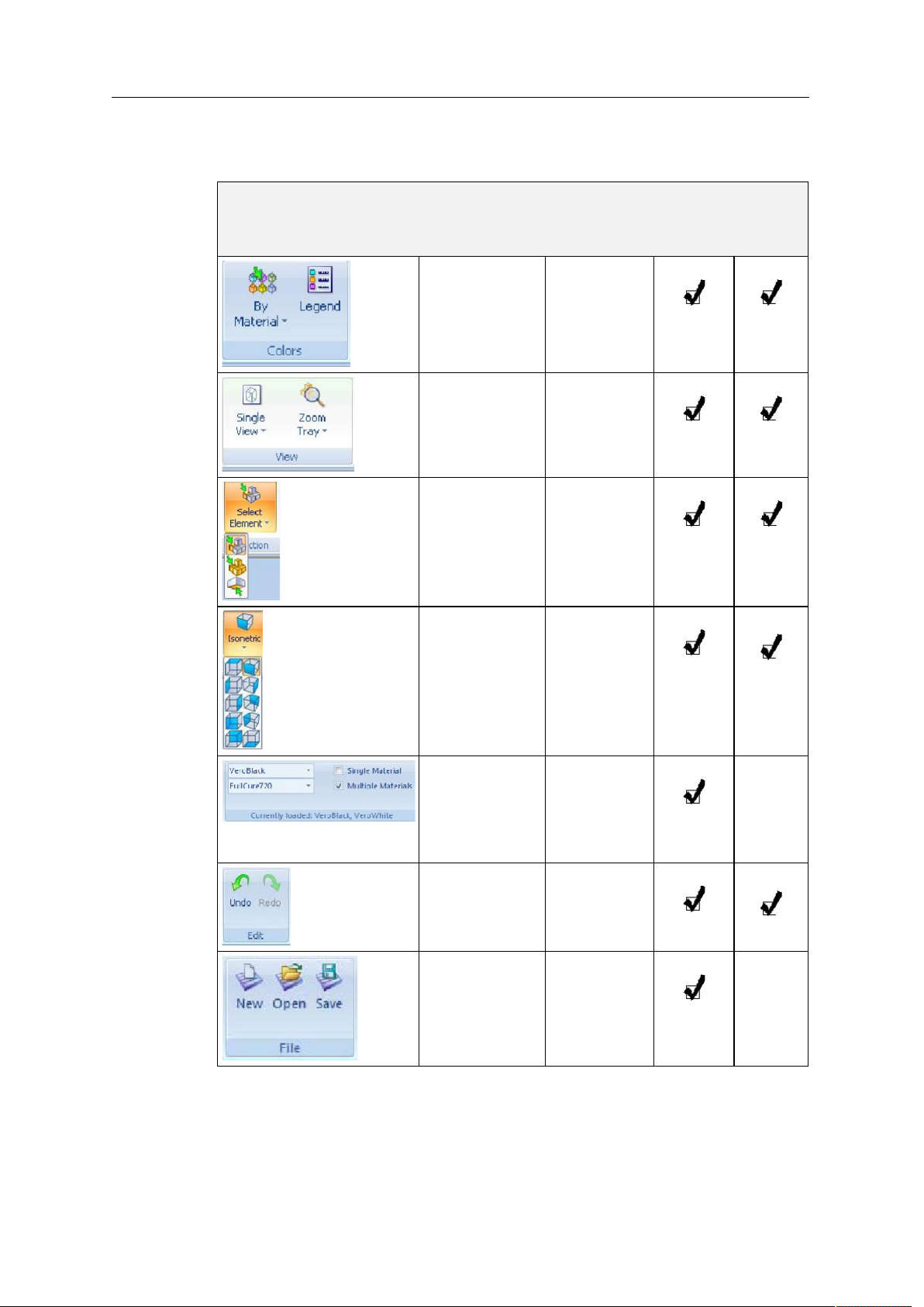
Ribbon
Commands
The following table lists the Tray Settings and Model Settings ribbon
command groups, and shows when they are enabled, and where they
appear.
Group Purpose When
enabled
Setting display
colors.
Selecting
perspective and
zoom level.
Choose to select
a plane,
elements, or
element groups
(assemblies).
Always.
Models are on
the build tray.
Models are on
the build tray.
Tray
Settings
Ribbon
Model
Settings
Ribbon
Change the
perspective of
the active pane.
Assigning model
material(s).
Undoing or
redoing actions.
Opening and
saving files.
Models are on
the build tray.
Build tray
•
is empty.
Models are
•
not
selected.
After an
action or
object
selection.
Models are
not selected
.
5–6
16 June
DOC-06800 Rev. A
Page 43

Objet1000 - Connex 2 User Guide
D R A F T
2013
Group Purpose When
enabled
Placing model
files on the build
tray
.
Pre build/build
commands.
Setting model
dimensions.
Cutting,
copying, pasting
and deleting
models.
Moving, rotating
and resizing
models.
Always.
Models are on
the build tray.
A model is
selected.
A model is
selected.
A model is
selected.
Tray
Settings
Ribbon
Model
Settings
Ribbon
Assigning a
•
material to a
model or
shell.
Separating a
•
model into
shells.
Assigning model
finish and
setting support
strength/
hollow.
Setting a models
unit of measure
(millimeters or
inches).
A model is
selected.
A model is
selected.
A model is
selected.
To quickly identify an icon, move the cursor over it to display a tooltip. The
“Undo” and “Redo” tooltips change to reflect your last Objet Studio action.
DOC-06800 Rev. A
16 June
5–7
Page 44

Using Objet Studio
D R A F T
2013
Objet Studio
Commands
Menu
Clicking the icon in the upper left corner opens the Objet Studio
Commands menu. This menu displays basic application commands and
options.
Figure 5-7: Objet Studio Commands menu
The Options button opens a dialog box for customizing Objet Studio.
Model Tree
Pane
5–8
Figure 5-8: Options dialog box
The Model Tree pane lists the objects placed on the build tray in a parent
child hierarchy. By default, the pane floats that is, you can move it to
another position on the screen and resize it. Alternatively, you can fix its
position at the left of the application window, and even hide it.
DOC-06800 Rev. A
16 June
Page 45

Preparing Models for Production
D R A F T
2013
Model preparation involves the following basic steps:
1. Place objects or assemblies on the build tray.
2. If necessary, manipulate the objects orientation and position.
3. Select the materials and model finish.
Just as Objet printers can produce different models on the build tray using
different materials, you can produce components of a model with different
materials. To do this, each part of the model must be a separate stl file. If the
models component parts were not saved in the CAD software as separate
stl files, you can use Objet Studio to separate the model into component
parts. (This is described in Splitting Objects into Components on page 18
and in Dividing Objects on page 54.)
Objet1000 - Connex 2 User Guide
OBJDF Files:
Overview
An objdf file describes both the geometry of a single object and the
materials, and finish required to print it. The objdf file can represent an
object that is a single stl file, or an object assembled from component stl
files.
Objet Studio enables you to split an stl file representing a complex object
into an assembly of component stl files, and save the assembly as an objdf
file. Each part (stl file) described by the objdf file can have its own model
material characteristic, so that the Objet printer produces the component
parts from specific materials.
Another use for objdf files is for saving a group of separate objects on the
build tray as one unit, together with their relative positions and materials.
This is especially useful for producing models in the future with the same
materials. In fact, when you save objdf files, you specify materials for
printing models without regard to the material cartridges loaded in the
printer. The same object can later be placed on build trays for printing. Each
time you send a build tray to the printer, you decide whether to allow
printing with substitute materials or only with the materials specified.
The Connex version of Objet Studio enables you to display, manipulate and
print component parts of a model assembly that was saved as an objdf file,
since each component is a separate stl file. This can be useful for printing
only specific parts of a model.
Further explanations of files, and their features, appear throughout this
chapter.
Model Files
DOC-06800 Rev. A
To produce models, you open one or more model files in Objet Studio and
position objects on the build tray. You can place objects on the build tray in
several ways:
by inserting individual stl or slc files (or an assembly of stl files).
•
by inserting an objdf file (an assembly).
•
by pasting objects that you copied to the Windows clipboard.
•
16 June
5–9
Page 46

Using Objet Studio
D R A F T
2013
Placing
Objects on the
Build Tray
To place an object on the build tray using stl, slc or files:
1. Open the Insert dialog box
From the Object menu, select
•
Insert
.
or
On the Tray Settings ribbon, click .
•
or
Right click on the build tray, and select
•
Insert
from the context
menu.
The Insert dialog box appears.
Figure 5-9: Insert dialog box
2. In the Look in field, display the appropriate folder.
3. In the Files of type field, select the file types to display (stl, slc, objdf).
4. Select the desired file, and make sure that it appears in the File name
field.
If the Preview check box is selected, the object is displayed in the dialog
box, as shown in figure 5 9.
Note: You can open several stl files at once, to place several models on the
build tray. If you select multiple stl files that make up an assembly,
you can select all or some of the parts. To print the entire model,
select all of an assembly’s component stl files, and select the
Assembly check box. This positions the parts as a complete,
integrated model instead of as independent parts. The effects of
selecting the Assembly check box—in both the model tree and the
build tray display—are shown in the following figures.
5–10
Figure 5-10: Assembly check box selected—stl files are placed as an assembly
DOC-06800 Rev. A
16 June
Page 47

Objet1000 - Connex 2 User Guide
D R A F T
2013
Figure 5-11: Assembly check box not selected—stl files are placed as parts
The Model Settings ribbon is displayed when objects are placed on the
build tray.
5. Select any of the following options, as required:
Units
•
Millimeters or inches for the objects units of measure.
The 3D file contains the object s proportions, but not its units of
measure. Therefore, make sure to correctly select either
inches
or
when inserting an object. Otherwise, the size of the object
millimeters
on the build tray will be either much too large or much too small. To
change the measurement units of objects already placed on the tray,
see Measurement Units on page 33.
Number of copies
•
How many copies of this object to place on the
build tray.
Orient Automatically
•
Automatically orient objects on the build
tray for efficient model building.
Assembly
•
Mark this check box if you selected multiple stl files
that are part of an assembly.
Note: The Extents values displayed in the Coordinates section of the Insert
dialog box, represent the maximum dimensions of the object on each
axis. These dimensions correspond to the virtual “bounding box”
surrounding the object see figure 5-51 on page 40).
DOC-06800 Rev. A
16 June
5–11
Page 48

Using Objet Studio
D R A F T
2013
6. Click
Insert
.
Objet Studio places the object on the build tray, and in the model tree.
Model
Tree
pane
Model
Toolbar
Figure 5-12: Default screen layout
The Model Settings ribbon is displayed when objects are placed on the
build tray.
If the object is over a certain size, the Loading Placed Elements dialog box
may appear.
Figure 5-13: Loading Placed Elements dialog box
You can speed up the opening of large files by changing the Large Files
settings—see “Loading Large Files” on page 44).
5–12
16 June
DOC-06800 Rev. A
Page 49

Objet1000 - Connex 2 User Guide
D R A F T
2013
Opening files Before placing files on the build tray, Objet Studio must extract the
component stl files together with information about their relative position
and model materials. To do this, Objet Studio creates a folder with the same
name as the file, in the same location.
Figure 5-14: Insert dialog box (file)
DOC-06800 Rev. A
16 June
5–13
Page 50

Using Objet Studio
D R A F T
2013
Opening Objet
Tray Files
You can open trays that were saved as objtf files. This is useful, for example,
if you saved a tray after preparing it for printing, and now you want to
make changes before printing it.
To place an object saved as an Objet Tray File (objtf) file on the build
tray:
1. From the File group, click .
or
From the Objet Studio Commands, select
Open
.
The Open dialog box is displayed.
Figure 5-15: Objet Tray File Open dialog box
2. Select the desired file, and make sure that it appears in the File name
field.
If the Preview check box is selected, the object is displayed.
3. Click
Open
.
Objet Studio opens the tray file.
The objtf file is actually a file containing instructions for printing—which stl
files to print and their position on the build tray. Because the objtf file
references the stl files used, they must remain in the same file location as
when the objtf file was saved.
5–14
16 June
DOC-06800 Rev. A
Page 51

Objet1000 - Connex 2 User Guide
D R A F T
2013
STL file loading
preference
If there are identically named stl files in more than one location, you need
to ensure that the correct component stl files are linked to the objtf file. For
example, if there are identically named stl files on one drive and on a flash
drive (this can occur if you copy the original files to a working folder), you
can set the default location from which files are loaded.
To set the Load Order:
1. From the Tools menu, select
Options
.
or
In the Objet Studio Commands Menu, click
Options
.
2. In the Options dialog box, display the Settings tab.
Figure 5-16: Options dialog box, Settings tab
3. Under Load Search Order, select an option:
to load files from the location where they were last saved.
Local
•
Original
•
to load files in their original location.
4. ClickOK.
DOC-06800 Rev. A
16 June
5–15
Page 52

Using Objet Studio
D R A F T
2013
Quick-Access
Model
You can access common commands for working with objects on the build
tray with the convenient Model Toolbar and context menus.
Commands
Model Toolbar Select an object in the tray to display the Model Toolbar that contains icons
to perform common tasks.
Figure 5-17: Model Toolbar
The table below describes the Model Toolbar icons.
Icon Description
Applies a matte finish to the model.
Applies a glossy finish to the model.
Opens the Advanced Properties dialog box for setting the
Grid Style and the Hollow option.
Right-click model
menu
Enables dragging an object (see page 5 34).
Opens the Transform dialog box for changing the
objects position and scale.
Toggles the Lock Model Orientation setting.
Allows you to choose the printing materials.
Enables you to apply a coating to the model, or change
the coating previously applied.
If you right click on an object, a pop up context menu is displayed from
which you can also select the model finish, change its position and scale,
and set the Grid Style and Hollow options.
You can also create a Quick Access toolbar with your most commonly used
icons grouped together. See “Creating a Quick Access Toolbar” on page 60.
5–16
16 June
DOC-06800 Rev. A
Page 53

Objet1000 - Connex 2 User Guide
D R A F T
2013
Copying and
Pasting
Objects
If you need to duplicate objects on the build tray, you can insert the same
object from its file more than once. An easier way, however, is to copy and
paste the object. You can copy objects from the build tray or the model
treeindividual or multiple parts or assemblies. The objects copied remain
in the Windows clipboard until you paste them onto the build tray.
You can also copy objects from one tray and paste them onto another, in the
same way as you copy text from one document and paste it into another
one. However, Objet Studio allows only one tray to be open at a time. For
each build tray you need to work with (at the same time), you must open a
separate Objet Studio window, by running the application again (from the
Windows Start menu).
Having multiple Objet Studio windows open can be convenient when you
need to manipulate or configure objects before inserting them in your
production build tray. For example, if you need to change the model material
of an object (saved as an objdf file) to match the model material already
used in the production build tray, you must do so before inserting the
object—on another tray. Copying and pasting also allows you to use objects
already configured on previously-used build trays for newer projects.
You perform the Copy and Paste commands as in other Windows
applications:
from the right click context menu.
•
by using keyboard shortcuts (Ctrl+C and Ctrl+V, respectively).
•
The Paste Special command (from the objects right click context menu)
enables you to place duplicate objects even more efficiently:
You can specify the number of duplicates to place on the build tray at
•
once.
You can set the distance, on each axis, between the duplicate objects.
•
You can manipulate mirror images of the original object, and flip them
•
on selected axes.
DOC-06800 Rev. A
Figure 5-18: Paste Special dialog box
5–17
16 June
Page 54

Using Objet Studio
D R A F T
2013
Selecting
Objects
To manipulate an object on the build tray or assign characteristics to it
(model material, building style etc.), you must first select the object. You
select an object by clicking it, either on the tray or in the model tree. Its
image on the build tray changes color (to light blue, by default) and its
name is highlighted in the model tree. You can select multiple objects by
drawing a box around them with the mouse cursor, or by pressing the
or
keys while clicking additional objects.
Shift
Ctrl
Alternatively, select or de select objects using the following Edit menu
commands:
Select All
•
Invert Selection
•
Undo Select object
•
Figure 5-19: Edit menu
Sometimes, you need to select individual elements of an assembly. Other
times, you need to select the entire assembly. The Selection icon displayed
on the ribbon determines what will be selected when you click on the
model:
Splitting
Objects into
Components
or
To change the selection action:
1. On the Tray Settings or Model Settings ribbon
a. Click the Selection icon: or .
b. On the flyout toolbar, click the appropriate icon:
Select Element
Select Group
Figure 5-20: Selection flyout toolbar
You can convert a complex object to an assembly of component parts. To do
so, you split the stl file that represents the object into a group of separate stl
files, each one representing a component. (This is referred to in the Objet
Studio interface as separating the object into shells.) You can then assign a
model material to each stl file, and you can save the newly created
assembly as an objdf file.
5–18
16 June
DOC-06800 Rev. A
Page 55

Objet1000 - Connex 2 User Guide
D R A F T
2013
To split an object into an assembly of component parts:
1. If the object is not displayed, place it on the build tray by inserting its stl
file (see Placing Objects on the Build Tray on page 10).
The object appearson the build tray and in the model tree paneas a
single part. It is assigned, by default, the primary model material. (If
Objet Studio is configured with a secondary material, you can assign
itor a digital materialto the entire object. This is explained in
Model Material Settings on page 20.)
Figure 5-21: Object placed on the build tray from a single stl file
Note: There is no need to resize or arrange the object on the build tray at
this time.
2. With the object selected:
From the Object menu, select
•
Separate into Shells
.
or
On the ribbon, click .
•
A dialog box opens in which you can specify where to save the
component stl files. (By default, Objet Studio offers to save the new files
in a folder in the same location as the original stl file.)
Figure 5-22: Folder selection for saving stl files after splitting into shells
3. ClickOK.
DOC-06800 Rev. A
16 June
5–19
Page 56

Using Objet Studio
D R A F T
2013
Objet Studio splits the object into an assembly of component parts, each
a separate stl file (shell).
The object appearson the build tray and in the model treeas an
assembly of parts (shells). You can assign each part a different model
material (This is explained in Model Material Settings on page 20).
Figure 5-23: Object after being converted to an assembly of component parts
Model-Material
Settings
Before placing objects on the build tray in Objet Studio, you should pay
attention to the material selection settings on the Tray Settings ribbon.
Figure 5-24: Material selection settings
By default, the material selection settings on the ribbon correspond to
•
the model cartridges loaded in the printer.
The materials displayed are basic model materials. These materials can
•
later be combined to create digital materials (see Digital Materials on
page 21).
The material displayed on the top (VeroWhite, in the figure above) is
•
considered the primary model material (Model 1). It is assigned to
objects that do not have a material assignment when you place them on
the build tray. For example, since stl files do not contain information
about the model material, Objet Studio assigns the primary model
material to them. Also, if you try to insert objdf files whose assigned
materials are not recognized by your version of Objet Studio, you can
insert the file by substituting the primary model material for the
missing materials.
•
Select
Single Material
if you want to print using only one material
both of the material drop down menus contain the same material. If
you decide to print with multiple materials, the material in the top
drop down menu remains assigned to the object until you select
another material.
If you insert an objdf file into an empty build tray, and the model
•
material assignment does not match the settings on the Tray Settings
ribbon, these settings are changed automatically. However, if there is an
5–20
16 June
DOC-06800 Rev. A
Page 57

Objet1000 - Connex 2 User Guide
D R A F T
2013
object already on the build tray whose materials do not match the
material assignment in the objdf file, you cannot place the new object on
the tray. To print this object, you have the following options:
Instead of printing it on the same build tray, print the new object as a
separate job.
Change the materials assigned to objects on the build tray to match
those assigned to the new object (see Changing the Model
Material and Assigning a Model Material to Objects, below).
Change the materials assigned to the new object before inserting it,
so there is no conflict with the settings on the Tray Settings ribbon.
To change the materials assigned to an object before inserting it:
1. Open another Objet Studio window, by running the application from
the Windows Start menu.
2. Insert the new object (objdf file) into the empty build tray.
3. Change the material selection settings on the Tray Settings ribbon to
those used on the other build tray.
4. Assign materials to the object (see Assigning a Model Material to
Objects on page 22).
5. Select the object and copy it.
6. Display the other Objet Studio window, and paste the object onto the
build tray.
Changing the
Model Material
Digital
Materials
Note: You can save the object with the new materials either as a new objdf
file, or by saving the original file with the changes.
When you design a build tray in Objet Studio, you can use model materials
that may not be currently installed in the printer. Because the installed
materials are displayed by default, change the material selection settings on
the Tray Settings ribbon, if necessary.
When two different model materials appear on the ribbon, you can produce
objects from either material or from a combination of themdigital
materials. Different pairs of model materials enable you to print objects
using unique digital materials. Certain digital materials can produce
objects with different shades of color. Combinations of model materials
that have different mechanical properties result in digital materials with
unique characteristics.
DOC-06800 Rev. A
16 June
5–21
Page 58

Using Objet Studio
D R A F T
2013
To view the digital materials available for printing objects (using two
basic model materials):
1. Make sure that you have selected the appropriate model materials, and
Multiple Materials
that
Figure 5-25: Material selection with two basic model materials
is selected.
2. Click .
The Material Selection Guide appears, showing the basic model
materials (at the top of the list) and the digital materials available
(combinations of them).
Assigning a
Model Material
to Objects
Figure 5-26: Material Selection Guide, showing the digital materials
available with the basic model materials
You can assign any of the available digital materials to objects on the build
tray.
To assign a model material to objects:
1. Select an object on the build tray (see Selecting Objects on page 18).
When an object is selected, its propertiesincluding model materials
are displayed on the Model Toolbar and on the ribbon.
Ribbon
Model Toolbar
Figure 5-27: Object properties, on ribbon and Model Toolbar
5–22
16 June
DOC-06800 Rev. A
Page 59

Objet1000 - Connex 2 User Guide
D R A F T
2013
2. Display the material pull down menu and select the desired material.
Figure 5-28: Menu for assigning materials to objects
When you de select the object on the build tray, it is displayed, by
default, with the color of the material you selected. In the same way,
you can assign model materials to each of the independent objects on
the build tray.
To separate an object into independent, component parts (each an stl file),
see “Splitting Objects into Components” on page 18.
Surface Finish
Coating
Objects
Models can be printed with a matte or glossy surface finish. To create a
matte finish, the printer surrounds models with a thin layer of support
material.
To set the model finish:
1. Select the model.
2. Select
Model Settings ribbon, Options group
•
Model Toolbar
•
right click context menu (when selecting the model)
•
Matte
or
Glossy
in one of the following places:
You can configure Objet Studio to distinguish between objects surface
finish on the build tray by color. To configure how Objet Studio displays
objects, see Setting Object Colors on page 43.
You can print composite models where the surface layer is a different
material than the inside. This can be useful to achieve unique mechanical
and textural characteristics. This technique is called coating.
To coat an object with a different model material:
1. Select an object on the build tray.
2. On the Model Toolbar or the Model Settings ribbon, click .
The Coat with dialog box opens.
DOC-06800 Rev. A
16 June
5–23
Page 60

Using Objet Studio
D R A F T
2013
3. Select
Coat With
and, from the pull down menu, select the coating
material.
Figure 5-29: Coating material selected
4. In the Thickness field, enter a coating thickness between 0.3 and 3
millimeters.
Note: The coating thickness does not affect the external dimensions of the
object, which remain unchanged. The coating layer replaces part of
the main model material.
5. Click
Apply
.
Note: When you de-select objects, they are displayed, by default, with
colors representing the model-material. Even after adding a coating
to an object, its color remains that of the main material, not the color
of the coating material.
To inspect, modify or remove the coating applied to an object:
1. On the Model Toolbar or the Model Settings ribbon, click .
The Coat with dialog box opens.
2. Perform one of the following actions
Change the coating settings, and click
•
To remove the coating, clear the Coat With check box and click
•
Apply
.
To keep the current coating settings, click
•
.
Apply
ApplyorCancel
.
5–24
16 June
DOC-06800 Rev. A
Page 61

Objet1000 - Connex 2 User Guide
D R A F T
2013
Assigning
Properties to
Hidden
Objects
To enable you to assign materials and other properties to parts of objects
that are hidden from view on the build tray display, you can temporarily
turn off the display of some objects.
To prevent the display of objects:
1. Right click an object, either on the build tray or in the model tree.
2. From the menu that opens, select one of the following options
, to cause the selected object to disappear.
Hide
•
Hide Others
•
, to cause all other objects on the build tray to
disappear, so that only the selected object is displayed.
Alternately, you can clear the check box next to the name of the
object in the model tree to cause that object to disappear.
Figure 5-30: All objects displayed Figure 5-31: Outer object hidden
DOC-06800 Rev. A
16 June
5–25
Page 62

Using Objet Studio
D R A F T
2013
Positioning Objects on the Build Tray
To produce models efficiently and with the required finish, it is important
to carefully position objects on the build tray. Objet Studio supports the
automatic positioning of objects. However, you should check to make sure
that the objects are orientated logically for your needs, according to the
considerations explained in Model Orientation on page 5 29.
Two things that affect the positioning of objects on the build tray are
orientation and placement. You can let Objet Studio determine the optimum
orientation and position, or you can control them.
Automatic
Orientation
By default, Objet Studio automatically orients objects, when placed on the
build tray, for the shortest printing time. (You can later change the
orientation manually.) However, you can cancel automatic orientation
when placing an object on the build tray.
To place an object on the build tray without automatic orientation:
In the Insert dialog box, make sure Orient Automatically is not selected.
5–26
Figure 5-32: Orient Automatically option disabled
You can change the default setting, so that automatic orientation is not
applied unless you select the Orient Automatically check box each time you
place an object on the build tray. To do this, see “Default Settings” on
page 66.
DOC-06800 Rev. A
16 June
Page 63

Objet1000 - Connex 2 User Guide
D R A F T
2013
Automatic
Placement
After placing several objects on the build tray, you can let Objet Studio
arrange them on the tray for printing. This ensures that the objects are
positioned properly, and that they will be printed in the shortest time and
with a minimum of material.
To automatically arrange objects on the build tray:
On the Tray Settings ribbon, click .
or
From the Tools menu, select
Automatic Placement
.
The effects of automatic positioning are shown in the figures below.
Figure 5-33: Tray before objects are properly arranged
DOC-06800 Rev. A
16 June
5–27
Page 64

Using Objet Studio
D R A F T
2013
Figure 5-34: Tray arrangement after applying Automatic Placement
For best results arrange the tray with Automatic Placement, on the Tray
•
Settings ribbon, even if you inserted the objects with the Orient
Automatically option.
The physical characteristics of each type of model material you use can
•
affect the positioning of objects on the build tray. Therefore, select the
material before running Automatic Placement.
Manual
Positioning
You can change the position of objects on the build trayeven if they were
inserted with the Orient Automatically option. Considerations for
positioning objects are presented in Model Orientation, below. Tools for
changing the position of objects are presented in Manipulating Objects on
the Build Tray on page 5 30.
5–28
16 June
DOC-06800 Rev. A
Page 65

Model Orientation
D R A F T
2013
The orientation of models on the build tray affects how quickly and
efficiently they will be produced by the 3D printer, where and how much
support material is used, and whether or not model parts will have a glossy
finish. Therefore, you should consider a variety of factors when deciding
how to place models on the tray, using the following positioning rules.
X-Y-Z Rule
This rule considers a model s outer dimensions.
Objet1000 - Connex 2 User Guide
Since the print heads move back and forth along the X axis, the printing
time along this axis is relatively short, compared to printing time along
the Y axis and Z axis. From this point of view, it is advisable to place the
object s largest dimension along the X axis.
Any surfaces that come into contact with support materials become
matte.
Since high resolution models are built up, on the Z axis, in 16 or
30 micron layers (according to the selected printing mode, it is very
time consuming to print a tall object. From this point of view, it is
advisable to place the object s smallest dimension along the Z axis.
Since the print heads measure about 2 inches (5 centimeters) on the
Y axis, models measuring less than this (on the Y axis) are printed in
one pass. From this point of view, it is advisable to place the object s
intermediate dimension along the Y axis.
Tall-Left Rule
This rule considers models where, after being orientated on the build tray
according to other considerations, one side is taller than the other.
Since the print heads move along the X axis from left to right, taller
sections on the right require the print heads to scan unnecessarily from
the left until reaching them. If, on the other hand, the taller sections are
positioned on the left of the tray, the print heads only have to scan the
model until printing these sectionsonce the lower parts have been
completed. Therefore, you should position the taller side of the model,
when possible, on the left.
The following rules are based on the fact that support material is not
required on the top of the printed model.
Recess-Up Rule
This rule considers models containing surface recesses.
Recesses in the surface (like hollows, drill holes, etc.) should, when
possible, be positioned face up.
Fine-Surface Rule
This rule considers models that have one side on which there are fine
details (like the keypad side of a telephone).
The side of the model containing fine details should, when possible, be
positioned face up. This results in a smooth finish.
DOC-06800 Rev. A
16 June
5–29
Page 66

Using Objet Studio
D R A F T
2013
Avoid Support-Material Rule
This rule considers models that have large holes or hollows, open on at
least one side (like a pipe or a container).
It may be advantageous to print a model standing up, so support
material does not fill the hollow, even though printing the model lying
down would be much faster.
Manipulating Objects on the Build Tray
Positioning
Objects on the
Z-Axis
When you use the automatic positioning option to arrange objects on the
build tray (see Automatic Orientation on page 5 26), the objects are
positioned directly on the tray. If you do not insert objects with automatic
positioning, they often appear either above or below the tray.
In practice, the Objet system prints all models on the build tray on a onemillimeter bed of support material. The importance of positioning objects
directly on the build tray with Objet Studio is to correctly display the objects
on the screen.
To position objects directly on the tray:
1. Select the object.
2. From the Object menu, select
Lay On
.
To ensure that objects are always positioned directly on the tray:
1. From the Tools menu, select
Options
, and display the Settings tab.
5–30
Figure 5-35: Options dialog box, Settings tab
2. In the Automatic Lay On (Gravity) section, select
Always
Other Z-axis options (in the Automatic Lay On section):
When under the tray
•
The display of objects that are below the build
tray is automatically changed so that the object is at tray level.
The display of objects that are above or below the build tray is
Never
•
not changed.
16 June
.
DOC-06800 Rev. A
Page 67

Objet1000 - Connex 2 User Guide
D R A F T
2013
Valid Object
Placement
You can ensure that models do not overlap when you position them on the
build tray, and that they do not extend beyond the tray.
To ensure valid object placement:
1. From the Tools menu, select
Figure 5-36: Constraints Settings dialog box
2. Select
Dynamic check
invalid object placement while placing objectsOn Drop selected.
•
invalid object placement after moving objectsWhile Drag selected.
•
objects placed beyond the trays boundariesOutside Tray selected.
•
objects that overlapObject Collision selected.
•
Constraints Settings
to identify:
.
Even if you do not use Dynamic Check when placing objects on the build
tray, Objet Studio automatically checks if there is a problem with the
positioning of objects on the tray before sending it to the printer. You can
also manually check for problems after positioning objects (see “Tray
Validation” on page 47).
Note: Because of the unique characteristics of each type of model material
and finish, always check valid placement after changing the material/
finish. Remember that Objet Studio calculates the space occupied by
an object including the “bounding box” surrounding it (see
figure 5-51 on page 40).
DOC-06800 Rev. A
16 June
5–31
Page 68

Using Objet Studio
D R A F T
2013
Using a Grid to
Position
Objects
Displaying a grid on the image of the build tray can be useful when
positioning objects. To use the grid features, select the following menu
options.
Menu Option Result
Tools > Grid Displays a grid on the build tray.
Tools > Snap to grid When moving the object, it aligns with the nearest
Tools > Options >
Grid
grid line.
Enables you to change the grid origin
(X and Y axis meeting point) and appearance.
You can review and configure grid settingsand apply themfrom the
Options dialog box.
To view and change grid settings:
1. From the Tools menu, select
Options
, and display the Grid tab.
The current grid settings are displayed.
5–32
Figure 5-37: Options dialog box, Grid tab
2. As required, change the settings, and select or clear the check boxes.
3. Click
ApplyorOK
.
DOC-06800 Rev. A
16 June
Page 69

Objet1000 - Connex 2 User Guide
D R A F T
2013
3D files contain an object s proportions, but not its units of measure.
Therefore, make sure to correctly select either millimeters or inches when
inserting an object. Otherwise, the size of the object on the build tray will be
either much too large or much too small.
To set the measurement units when inserting an object:
In the Insert dialog box, Units field, select
MillimeterorInch
:
Figure 5-38: Units field in the Insert dialog box
To change measurement units for a selected object from the
Model Settings ribbon:
1. Open the Units flyout toolbar.
Figure 5-39: Units flyout toolbar
2. Select the measurement units desired.
To change measurement units for a selected object from the Standard
Toolbar:
1. From the Object menu, select
Change Units
.
DOC-06800 Rev. A
Figure 5-40: Model Units dialog box
2. In the Model Units dialog box, change the setting and clickOK.
5–33
16 June
Page 70

Using Objet Studio
D R A F T
2013
Setting Model
Dimensions
Repositioning
Objects
You can change an objects dimensions by changing its size on the X , Y ,
and Z axes, from the Dimensions group on the Model Settings ribbon.
Figure 5-41: Dimensions on the Model Settings ribbon
If Uniform Scale is enabled, changing the objects dimension on one axis
•
affects the other dimensions, proportionately.
After changing a measurement, press Enter or click in another filed in
•
the Dimensions group.
Note: You can change the height of the objects on the build tray only if this
is allowed by the Objet Studio settings (see “Positioning Objects on
the Z-Axis” on page 5-30).
You can manually move and rotate an object on the build tray with the
arrow keys, or by dragging it with the mouse.
To manually manipulate an object:
1. Select an object by clicking it on the build tray, or in the model tree
pane.
2. Click on the Model Toolbar, or on the Model Settings ribbon.
A frame appears around the object, and the cursor changes to indicate
that the object can be moved.
Figure 5-42: Manually moving an object
5–34
16 June
DOC-06800 Rev. A
Page 71

Objet1000 - Connex 2 User Guide
D R A F T
2013
3. If you click on a corner of the frame, the cursor changes to indicate that
the object can be rotated.
Figure 5-43: Manually rotating an object
4. Manipulate the object with the arrow keys or with the mouse.
Using the Transform
Dialog Box
You can make precise changes to an object by changing the properties in the
Transform dialog box.
To access the Transform dialog box (when an object is selected):
Click on the Model Toolbar or on the Model Settings ribbon.
•
From the right click context menu, select
•
From the Object menu, select
•
Figure 5-44: Transform dialog box
Transform
Transform
.
.
To change an object with the Transform dialog box:
Change any of the values, then click
Apply
to see how the object
changes on the build tray.
Note: The changed values remain in the dialog box after clicking Apply.
Therefore, you can make small changes to values in the dialog box to see
how the object changes on screen each time you click Apply.
DOC-06800 Rev. A
To reset all of the values in the dialog box:
Click
Reset
.
To undo all changes made with the Transform dialog box:
Cancel Actions
Click
.
After closing the Transform dialog box, clicking Undo (on the Model Settings
ribbon or from the Edit menu) cancels all changes made with the dialog box.
16 June
5–35
Page 72

Using Objet Studio
D R A F T
2013
Changing an
Object’s
Orientation
There are several methods for changing the orientation of objects on the
build tray.
To rotate an object:
Select the object and use the Object menu options (see also
Repositioning Objects on page 5 34).
To re-align an object’s plane:
1. On the Tray Settings or Model Settings ribbon
a. Click the icon in the Selection group: or .
b. On the flyout toolbar, click the Select Plane icon:
or
From the Tools menu, select
Plane Alignment > Select Plane
.
2. Click on part of an object on the build tray.
The selected plane is displayed.
Alignment
toolbar
Selected
plane
Figure 5-45: Aligning by plane
3. On the Alignment toolbar, click an appropriate icon to change the
alignment.
or
From the Tools menu, select
Plane Alignment
, and select an alignment
option.
5–36
16 June
DOC-06800 Rev. A
Page 73

Objet1000 - Connex 2 User Guide
D R A F T
2013
Figure 5-46: Tools menu, Plane Alignment options
To cancel plane selection after re-aligning objects on the build tray:
On the Tray Settings or Model Settings ribbon
a. Click the icon in the Selection group: or .
b. On the flyout toolbar, click the Select Element or Select Group icon:
Grouping and
Ungrouping
Objects
or
From the Tools menu, select
Plane Alignment > Select Plane
.
To flip an object 180 degrees on any axis:
1. Select the object.
2. From the Object menu, select
Flip > Flip X / Flip Y / Flip Z
.
To make precise changes to the object’s orientation on any axis:
1. Select the object.
2. Display the Transform dialog box (see figure 5 44 on page 35).
3. Change the
Rotate
parameters for each axis.
You can manipulate two or more objects on the build tray, at the same time.
Selecting multiple objects
•
Manipulating done to one object affects all selected objects. For
example, turning one object on its axis causes all selected objects to turn
on their respective axes.
Converting the objects to an assembly
•
Separate objects become parts of one unit. For example, turning the
assembly on its axis causes all its component parts to turn as one unit.
To convert objects to an assembly:
1. Select the objects (see Selecting Objects on page 18)
2. From the Object menu, select
Group to Assembly
.
DOC-06800 Rev. A
16 June
5–37
Page 74

Using Objet Studio
D R A F T
2013
In the model tree, the objects now appear as children of a parent
(assembly).
Figure 5-47: Assembly in the model tree
After creating an assembly, you can save it as an objdf file, for re use.
(Saving the assembly is not necessary for manipulating and printing it).
To save an assembly:
1. Select the assembly (either on the build tray or in the model tree).
2. From the Objet Studio Commands, select Save As.
3. In the
Save As
dialog box, select the objdf format, choose a location,
name the file, and click
Save
.
Freezing Model
Orientation
To separate assemblies into individual objects (stl files):
1. Select the assembly (either on the build tray or in the model tree).
2. From the Object menu, select
Ungroup
.
In the model tree, the elements are not parts of an assembly.
Figure 5-48: Separate objects in the model tree
If you manipulate an object on the build tray, you can freeze its orientation
so that it does not change when you position it automatically (see
Automatic Placement on page 5 27).
To freeze an object:
1. Select an object on the build tray.
2. On the Model Settings ribbon, in the Manipulate group, or on the Model
Toolbar, click .
5–38
To unfreeze an object:
Select the object and click (to de select it).
DOC-06800 Rev. A
16 June
Page 75

Display Options
D R A F T
2013
Objet1000 - Connex 2 User Guide
Viewing
Objects
From the View menu, you can change the way objects are displayed. The
default method for displaying models on the build tray is as solid
(shaded) objects.
Figure 5-49: Tray and model displayed in Shaded view
The other display options are WireFrame and Points.
To display the build tray in WireFrame view:
From the View menu, select
WireFrame
.
DOC-06800 Rev. A
Figure 5-50: Tray and model displayed in WireFrame view
To revert to the shaded view:
From the View menu, select
16 June
Shaded
.
5–39
Page 76

Using Objet Studio
D R A F T
2013
To display objects as boxes, showing their maximum dimensions
instead of their shape:
From the View menu, select
Figure 5-51: Model displayed with bounding box
Display Bounding Box
.
To display the area around objects needed for support material (to
produce a matte finish):
From the View menu, select
Display Thickening Box
.
Figure 5-52: Model displayed with thickening box
To display the maximum build height:
From the View menu, select
Figure 5-53: Tray 3D Box
Display Tray 3D Box
.
To display objects without the build tray:
From the View menu, clear (de select) the Display Tray option.
5–40
16 June
DOC-06800 Rev. A
Page 77

Objet1000 - Connex 2 User Guide
D R A F T
2013
Screen Layout
Objet Studio automatically adjusts the default screen layout to display the
optimum views of the build tray and the model tree. You can view models
from different perspectives by changing the screen layout.
To change the screen layout:
On the View flyout toolbar, select
Figure 5-54: Screen layout icons
Single View
4 Views
is the default screen layout.
displays perspective, top, front and right views.
Single View
, or
4 Views
.
DOC-06800 Rev. A
Figure 5-55: Single-view screen layout
Figure 5-56: 4-view screen layout
5–41
16 June
Page 78

Using Objet Studio
D R A F T
2013
Tray
Perspective
The default perspective of the build tray is isometric. You can change the
perspective of the active window with one of ten options.
To change the perspective of the build tray in the active window:
1. On the Tray Settings ribbon, open the Perspective flyout toolbar.
Figure 5-57: Perspective flyout toolbar
2. Click the icon that represents the desired perspective.
Tray Positioning To view the tray and models from different directions, you can move the
tray around the screen and change its display angle.
To move the tray in the Objet Studio screen:
Press the mouse wheel while moving the mouse.
5–42
Figure 5-58: Tray after moving it in the Objet Studio display
DOC-06800 Rev. A
16 June
Page 79

Objet1000 - Connex 2 User Guide
D R A F T
2013
To manually rotate the tray:
Press Alt and press the mouse wheel while moving the mouse.
Setting Object
Colors
Figure 5-59: Tray after rotating it upside-down
The color of objects on the build tray can indicate how they are printed.
Objet Studio enables you to choose the color display so that you can easily
see the material, surface and coating of objects.
To choose how colors are applied on the display:
On the Model Settings ribbon, in the Colors group, select one of the
options from the flyout toolbar.
Color Indicates Model material
Color indicates Model surface
Color indicates if coating is used
Figure 5-60: Colors display options
Before sending a build tray to the printer, or when you perform tray
validation, Objet Studio checks if there is a problem with the stl files or the
positioning of objects on the tray. If so, the affected objects are displayed
with special colors (see “Tray Validation” on page 5-47).
DOC-06800 Rev. A
16 June
5–43
Page 80

Using Objet Studio
D R A F T
2013
Loading Large
Files
Very large stl files can be slow to load and may be difficult to manipulate
easily on the build tray. If this is the case, you can display just an image of
the object on the build tray without loading the entire file. The stl file itself
is not changed, and the complete file is sent to the printer.
To display an image of stl files when you place objects on the build tray:
1. From the Tools menu, select
Figure 5-61: Options dialog box, Settings tab
Options
2. In the Large Files section, select
, and display the Settings tab.
Load Partial (reduced)
.
Large File
Manipulation
If you need to work with a detailed model that is composed of a large
number of polygons, you can speed up its display and manipulation in
Objet Studio by reducing the number of polygons on the screen. Although
this may reduce the resolution on the screen, it has no affect on the printed
models.
Figure 5-62: Object displayed without polygon reduction
5–44
Figure 5-63: Object displayed with only five percent of its polygons showing
DOC-06800 Rev. A
16 June
Page 81

Objet1000 - Connex 2 User Guide
D R A F T
2013
To use polygon reduction:
1. From the Tools menu, select
Options
or
In the Objet Studio Commands Menu, click
2. In the Options dialog box, display the
.
Display
Options
tab.
.
Figure 5-64: Options dialog box, Display tab
3. Select
4. Select
Enable Polygon Reduction
Polygon Reduction (Percent)
.
.
5. Enter the percentage of total polygons to display.
When you click
, the display changes.
Apply
Note: The setting affects the static display (when the object is not being
moved).
6. Set display options when the object is being moved (Display while
changing view):
Bounding BoxA box representing the objects maximum
•
dimensions is displayed.
Adaptive Polygon ReductionVarying degrees of polygon reduction
•
are applied, as necessary.
Entire ObjectNo polygon reduction is applied.
•
7. To save these settings, so that they will be applied every time you place
this object on the build tray, click
8. Click
Apply
to see the results of the settings without closing the dialog
Save Polygon Reduction Data
.
box.
DOC-06800 Rev. A
Selecting the Entire Object option cancels polygon reduction.
5–45
16 June
Page 82

Using Objet Studio
D R A F T
2013
Object display
options
Zoom Options
The display format affects how quickly objects display. For example, if you
Bounding Box
select
Entire Object
. You can choose display formats for objects when they are
, objects display faster than they do when you select
stationary (static view) and for when you are dragging them (changing view).
To select the object display preference while changing view, and in static
view:
1. Select to display objects:
With a Bounding Box (see figure 5 51 on page 40)
•
With Adaptive Polygon Reduction (changing view only)
•
With Polygon Reduction (static view only)
•
Entire Object
•
2. ClickOKwhen done.
While manipulating objects, you often need to view them at different zoom
levels.
To change the zoom level:
On the ribbon, open the Zoom flyout toolbar and select an option:
Zoom Object
Zoom Tray
Zoom by Rectangle
Figure 5-65: Zoom flyout toolbar
Zoom Object focuses on the selected object.
Zoom Tray displays the whole tray.
Zoom by Rectangle allows you to display a section of the tray by
selecting it with the mouse.
You can also zoom in and zoom out with the mouse wheel.
You can configure Objet Studio to automatically zoom in on the objects
placed on the build tray. See “Automatic Zoom” on page 66.
5–46
16 June
DOC-06800 Rev. A
Page 83

Handling Completed Trays
D R A F T
2013
After you have properly placed all objects on the build tray, you save the
tray as an objtf file, which is sent to the 3D printer for production. But before
saving the tray, you can check that there would be no problem producing it.
You can also calculate how much material would be consumed during
production and how much time this would take.
Objet1000 - Connex 2 User Guide
Tray Validation
Before sending a job to the printer for production, you should check that
the tray is valid and can be printed.
Note: Because of the unique characteristics of each type of modeling
material, make sure that the correct material is selected before
performing Tray Validation.
To validate that the tray can be printed:
On the Tray Settings ribbon, in the Build Process group, click .
or
From the Tools menu, select
Placement Validation
.
If the tray is not valid, the color of the problematic models on the tray
changes according to a pre set code.
DOC-06800 Rev. A
Figure 5-66: Color code
Note: The “Both” color also indicates a problematic stl file.
The validation status appears on the bar at the bottom of the screen.
Figure 5-67: Validation details in status bar
5–47
16 June
Page 84

Using Objet Studio
D R A F T
2013
Production
Estimates
Objet Studio enables you to calculate the time and material resources
needed for producing trays before sending them to the printer. The time it
takes Objet Studio to perform this calculation depends on the number of
objects on the tray and their complexity. Calculating the production
estimate for a full tray could take up to 15 minutes, depending on your
computers specifications.
To calculate the time and materials needed for producing the current
tray:
On the Tray Settings ribbon, in the Build Process group, click .
While the estimate is being calculated, a progress bar is displayedon
the right side of the status bar (at the bottom of the screen).
Cancel
Figure 5-68: Estimate progress bar
When Objet Studio finishes calculating the production resources, the
results are displayed in a dialog box.
Printing Modes
Figure 5-69: Production resource calculations for different printing modes
As shown in the Production Estimates dialog box, the resources needed for
producing the models on the tray depend on the printing mode used by the
printer when producing the job. You might want to consider these
estimates when deciding on the printing mode (see below), and whether or
not to allow using substitute model materials when printing the job.
Note: You select the printing mode and material substitute options after
you send the build tray to the printer (see “Printing the Tray File” on
page 50).
Objet printers can build models using three possible printing modes.
HQ (High Quality) Mode—
Models are printed in 16 micron layers, resulting in smooth surfaces,
•
suitable for producing fine detailed and delicate items.
Almost twice as much time is required to print most trays, compared to
•
the High Speed setting.
This setting is only available when model material can be used in four
•
print heads, in single material printing.
5–48
16 June
DOC-06800 Rev. A
Page 85

Objet1000 - Connex 2 User Guide
D R A F T
2013
Single-material printing: All print heads print models without regard to the
source of the model material. This happens in the following situations:
All print heads are supplied with one model material.
•
Each pair of print heads is supplied with a different model material, but
•
models are printed as if they were the same material. The result is an
arbitrary mixture of materials in the printed model.
HS (High Speed) Mode—
Models are produced in 30 micron layers, suitable for producing larger
•
models.
Much less time is required to print most trays, compared to the
•
High Quality setting.
This setting is only available when model material can be used in four
•
print heads, in single material printing.
Digital Material Mode—
Used when producing models designed to be fabricated from two
•
model materials.
Used when producing a tray containing two or more models, each
•
designed to be made from a different (single) model material.
Used when producing models from only one of the model materials
•
loaded in the printer by printing with only two of the print heads.
Models are produced in 30 micron layers, but the printing is near high
•
quality.
Printing time is similar to printing time in High Quality mode.
•
Although printing time is longer than with High Speed mode, Digital
Material mode can make material replacement unnecessarysaving
both time and the cost of wasted model material.
E-mailing
Objet Digital
Files
Digital Material Mode is selected automatically when more than one model
material is assigned to objects on the tray.
You can see estimates of time and material resources needed for printing
trays using the different printing modes (see Production Estimates on
page 48). You also see these production estimates when you send the tray
to the printer. At that time, you can select the printing mode, including an
option that enables Objet Studio to print the tray by the most efficient
method (see Printing Mode Selection on page 50).
You can easily e mail objdf files using Microsoft®Office Outlook®. Sending
objdf files is recommended (instead of stl files) because the size of a file is
typically reduced by more than half. An added benefit is that the objdf file
contains the model material information for the object.
To e-mail a file:
1. From the Tools menu, select
Outlook opens with the file attached and Subject details added to the
e mail form.
2. Enter the e mail address and send the file.
Email Objet Digital File
.
DOC-06800 Rev. A
16 June
5–49
Page 86

Using Objet Studio
D R A F T
2013
Printing the
Tray File
When a tray is ready to be printed, it is placed in the Jobs Queue. When the
job reaches the head of the queue, Objet Studio pre processes the tray file to
create slices, and feeds them to the 3 D printer.
To send the tray to the print queue:
1. On the Tray Settings ribbon, Build Process group, click .
two model
materials
Figure 5-70: Job Summary when printing with multiple model materials
Note: The values displayed are the result of a quick calculation, and
represent a rough estimate of the materials and time input required
to print the job. For a more accurate calculation, click
Estimation
.
Fine
Continue with step 4 on page 5 53.
If printing the tray requires only one model material, the Printing
•
Mode Selection dialog box opens.
Printing-Mode
5–50
Selection
Figure 5-71: Printing Mode Selection dialog box
Note: The values displayed are the result of a quick calculation, and
represent a rough estimate of the materials and time input required
to print the job. For a more accurate calculation, click
Estimation
.
Fine
2. Select the appropriate printing mode.
If you require the job to be printed in High Quality mode, select this
•
option.
Note:The availability of High Quality mode depends on the material
selected.
16 June
DOC-06800 Rev. A
Page 87

Objet1000 - Connex 2 User Guide
D R A F T
2013
If you require the job to be printed in High Speed mode, select this
•
option.
If you do not require the job to be printed either in High Quality or
•
High Speed mode, select
Automatic
.
This setting enables the Objet software to determine (just before
printing) the most efficient way to print the tray. Digital Material mode
is used if this removes the need to perform the Material Replacement
procedure. Otherwise, High Speed mode is used.
For example, if printing the tray requires only one of the model
materials loaded in the printer, only the two print heads using that
material are used to print modelsDigital Material mode. (High
Quality and High Speed modes call for printing model material with
four heads, which would require you to perform the Material
Replacement procedure.)
On the other hand, if printing the tray can be done using four print
heads without running the Material Replacement procedure, High
Speed mode is used. This is possible if all print heads are supplied with
one model material, or if you allow printing with an arbitrary mixture
of similar materials (see below).
Model Quality When Digital Material Mode is Used
Near-high-quality is achieved for most models.
•
A tray of objects inserted from stl files are printed with the standard
•
600 dpi (dots per inch) resolution along the Y-axis—unless glossy finish
is required (see “Surface Finish” on page 23).
If there is an assembly on the tray, all of the models on the tray are
•
printed with a resolution of 300 dpi along the Y-axis.
3. Click
Next
.
The Model Material Substitution dialog box opensif this is relevant for
the tray. (If not, the Job Summary dialog box openscontinue with
step 4.)
DOC-06800 Rev. A
16 June
5–51
Page 88

Using Objet Studio
D R A F T
2013
Model Material
Substitution
Figure 5-72: Model Material Substitution dialog box
If you allow the use of substitute model materials, the printer will use
different materials whose characteristics (strength, flexibility, etc.) are
similar to those of the material you assigned to the object when
designing the build trayunder the following conditions:
The material you assigned is not installed in the printer at the time
•
of printing.
In this case, the tray is printed with either one or two substitute
materials (depending on the materials installed in the printer at the
time of printing). If possible, High Speed mode is used.
In addition to the material you selected, there is another (similar)
•
material installed in the printer at the time of printing.
In this case, High Speed mode is used, by printing with a mixture of
the two materials (as if they were the same material).
5–52
16 June
DOC-06800 Rev. A
Page 89

Objet1000 - Connex 2 User Guide
D R A F T
2013
4. Click
Build
.
If the build tray file has not been saved, the Save As dialog box opens for
you to save it now.
Objet Studio checks if there is a problem with the positioning of objects
on the tray. If so, the affected objects are displayed with special colors
(see Tray Validation on page 47), and a warning message appears.
Figure 5-73: Tray validation warning message
To cancel the Build command so you can correct the problem, click
•
.
No
To print the models as they are positioned on the tray, click
•
Yes
.
The Job Manager screen opens, so you can monitor the progress of your
traysbefore, during, and after printing. See Monitoring and
Managing Print Jobs on page 72.
DOC-06800 Rev. A
16 June
5–53
Page 90

Using Objet Studio
D R A F T
2013
Applying Additional Objet Studio Features
Dividing
Objects
You can use the Split Object feature to produce objects larger than the tray
area by dividing the model into separate parts. With this feature, you
produce only a specific section of a model.
To split an object:
1. Select the object.
2. From the Object menu, select
Split
.
3. In the Split Object dialog box, enter the values to determine how Objet
Studio will divide the object. You can divide an object along any of its
axes, by entering either exact measurements or the number of parts.
Figure 5-74: Split Object dialog box
4. In Save to Folder, enter the folder name.
5. ClickOK.
The composite parts are saved as new stl files with Part 1, Part 2,
etc., added to the original file name.
Note: Before printing the newly created stl files, it is recommended that you
check them for defects in an STL-repair application, such as
Magics™, by Materialise®.
5–54
16 June
DOC-06800 Rev. A
Page 91

Objet1000 - Connex 2 User Guide
D R A F T
2013
Choosing the
Support
Strength
When producing models, support material fills some hollow and empty
sections (see Model Orientation on page 5 29). Objet Studio allows you to
adjust the strength of the structure formed with the support material. This
adjustment is useful when producing either large/massive models or small/
delicate models. For most purposes, the default setting provides adequate
support strength.
To change the strength of the support structure used when printing a
model:
1. Select a model on the tray.
2. On the Model Settings ribbon, in the Options group, click
.
or
On the Model Toolbar, click
•
.
or
From the right click context menu, select
•
Advanced Properties
.
The Advanced Properties dialog box opens.
Figure 5-75: Advanced Properties dialog box
3. In the Grid Style section, choose the support strength suitable for the
selected model. You can select a different support strength for each
model on the tray.
Standard
•
Heavy
•
Lite
•
for models needing average support (most models).
for large models needing much support.
for delicate models needing little support. (This setting makes
it easy to remove the support material.)
Note: If an object is split into shells, the Advanced Properties enabled vary
with the object selection. If a single element is selected only Hollow
is enabled. If a group of elements is selected only Grid Style is
enabled.
4. Click
Apply
.
DOC-06800 Rev. A
16 June
5–55
Page 92

Using Objet Studio
D R A F T
2013
“Hollow”—
Filling Models
with Support
Material
Many objects placed on the tray from stl files are solid. This means that,
when printed, the model will be completely filled with model material.
Often, especially with large objects, this is unnecessary. Instead, the model
can be filled with support material, which is less costly. It is also advisable
to fill models with support material when preparing them for investment
casting, since this material burns off more quickly during the process of
making the cast.
Objet Studio enables you to print objects on the tray with an outer shell of
model material and a center filled with support material. When using this
feature, called Hollow, the thickness of the shell should be no less than
0.5 millimeters.
To use the Hollow feature:
1. Select a model on the tray.
or
On the Model Toolbar, click
•
.
or
From the right click context menu, select
•
Advanced Properties
.
The Advanced Properties dialog box opens.
2. Select
Hollow
.
Figure 5-76: Advanced Properties dialog box
3. Set the shell thickness, in millimeters.
4. Click
Apply
.
Note: There is no change in the display of objects in Objet Studio when
Hollow is selected.
To inspect, change or cancel the Hollow setting:
1. Select a model on the tray.
2. Access the Advanced Properties dialog box, as above.
3. If you change or cancel the Hollow setting, click
Apply
.
5–56
16 June
DOC-06800 Rev. A
Page 93

Objet1000 - Connex 2 User Guide
D R A F T
2013
Displaying the
Cross Section
of Objects
The Section feature enables you to view the interior of an object by slicing
it on any axis. You can then manipulate the object to inspect the interior
from different angles. This may be important for deciding on the type of
support necessary when producing the model (see Choosing the Support
Strength on page 5 55). Displaying an objects cross section only affects
how the tray is displayed on the screen; it does not change the object itself.
To display a cross section of the tray:
1. From the Tools menu, select
Section
.
The Section dialog box opens.
Figure 5-77: Section dialog box
2. Select
Enable Clipping
.
3. Use the slider controls for the X , Y , and Z axes to cut the tray so that
you see the cross section you want.
Figure 5-78: Whole view Figure 5-79: Cross-section view, after
using the Z-slider
DOC-06800 Rev. A
16 June
5–57
Page 94

Using Objet Studio
D R A F T
2013
Saving the
Screen Display
as an
Image File
You can save the image displayed in the active viewing screen as a graphic
file.
To save the screen display as an image:
1. Press
Ctrl+B
.
or
From the Objet Studio Commands Menu menu, select
Save Bitmap
.
The Save Bitmap dialog box opens.
Figure 5-80: Save Bitmap dialog box
2. At the top of the dialog box, select the appropriate folder.
3. At the bottom of the dialog box, enter a file name.
4. Open the Save as type pull down menu, and select the file format.
5. Click
Save
.
5–58
16 June
DOC-06800 Rev. A
Page 95

Objet1000 - Connex 2 User Guide
D R A F T
2013
Exporting and
Importing
Objet Build
Trays
When you save build trays in Objet Studio, they are saved as objtf files.
These files contain instructions to Objet Studio and to Objet printers for
displaying and producing the stl files used on the tray. To conveniently
save all of the files that comprise the build tray, for storing the job, or for
transferring it to another location, Objet Studio compresses them into one
objzf file. To later use the objzf file, the file must first be expanded in Objet
Studio and its component files saved.
Note: If you export an objzf file containing a stl file originally saved as read-
only, you cannot open (import) this objzf file to the folder where the
read-only stl file is saved.
To create an objzf file:
1. From the Objet Studio Commands Menu menu, select Export Packed
.
Job
The Save As dialog box opens.
2. Select the appropriate folder and change the file name (if necessary).
3. Click
Save
.
To open an objzf file:
Double click on the objtf file.
or
1. From the Objet Studio Commands Menu menu, select
.
Job
Import Packed
2. In the Open dialog box, display the appropriate folder and select the
file.
3. In the Browse for Folder dialog box, display the folder in which you
want Objet Studio to expand the compressed file, and clickOK.
The objtf file and associated stl files are expanded and placed in the
selected folder, and the tray is displayed in Objet Studio.
DOC-06800 Rev. A
Note: You can also export a print job as an objzf file from the Job Manager
screen—see “Exporting Jobs (objzf)” on page 83.
5–59
16 June
Page 96

Using Objet Studio
D R A F T
2013
Objet Studio
You can customize Objet Studio to suit your particular working needs and
preferences. Features that you can customize include:
Creating a quick access toolbar for frequently used commands.
•
Changing the position of the Quick Access toolbar.
•
Minimizing the ribbon.
•
Changing the Objet Studio color theme.
•
Configuring default settings for objects placed on the build tray.
•
Creating a
Quick Access
Toolbar
As you work with Objet Studio, you may use certain commands frequently.
You can create a quick access toolbar to make your work easier.
To create a quick-access toolbar:
1. Above the ribbon tabs, click
The Customize Quick Access Toolbar menu opens.
Figure 5-81: Customize Quick Access Toolbar menu
2. Select a command you want to add to the toolbar.
An icon for the selected command is added to the toolbar.
.
5–60
Figure 5-82: Quick Access toolbar
To add another command, repeat the above procedure.
DOC-06800 Rev. A
16 June
Page 97

Objet1000 - Connex 2 User Guide
D R A F T
2013
3. To choose from a wider range of commands:
From the Customize Quick Access Toolbar menu (see figure 5 81 on
•
page 60), select
More Commands
.
or
Right click on the Objet Studio Commands icon, or elsewhere on the
•
ribbon, and select
Figure 5-83: Right-click ribbon menu
Customize Quick Access Toobar
The Options dialog box opens.
.
Hiding the
Ribbon
Figure 5-84: Quick Access Toobar Options dialog box
4. Open the drop down list and select either
Commands not on the Ribbon
5. Select a command and click
Add
.
.
Popular Commands
or
6. ClickOK.
To make more room for displaying the build tray, you can hide the Objet
Studio ribbons.
To hide the ribbons:
1. Right click anywhere on the ribbon or on the menu bar, or in the Objet
Studio Commands Menu .
2. Select
Minimize the Ribbon
.
The ribbons disappear, but you can temporarily display the ribbon
icons by clicking
Tray Settings orJob Manager
on the menu bar. When
you next click outside of the ribbon, it disappears again.
To return the permanent ribbon display:
Repeat the steps above to cancel Minimize the Ribbon.
DOC-06800 Rev. A
16 June
5–61
Page 98

Using Objet Studio
D R A F T
2013
Display Colors
You can customize some of the colors used for displaying Objet Studio
screens and for displaying objects on the build tray.
To change the colors used in Objet Studio screens:
1. From the Tools menu, select
Define Colors
.
The Define Colors dialog box appears.
2. In the Define Colors dialog box, click the color patch you want to
change:
Tray Color
•
Background Colors
•
Selection Color
•
Figure 5-85: Define Colors dialog box
3. In the Color dialog box, select one of the Basic colors.
or
Define Custom Colors
Click
to expand the dialog box and define a
customized color.
Figure 5-86: Color dialog box (expanded)
4. Click
OK
when done.
The patch color in the dialog box changes according to your selection.
5–62
16 June
DOC-06800 Rev. A
Page 99
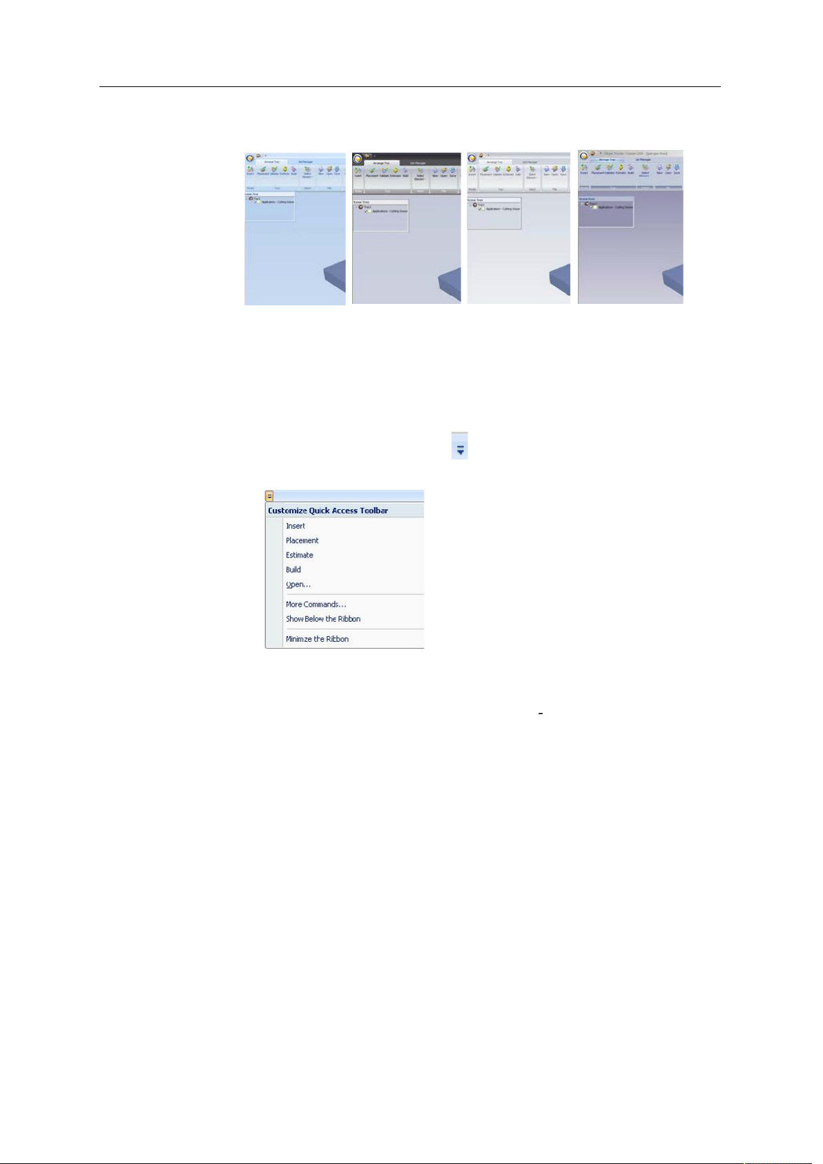
Objet1000 - Connex 2 User Guide
D R A F T
2013
Changing Color
Themes
Keyboard
Shortcuts
Objet Studio offers a choice of four background color themesblue, black,
silver and aqua.
Figure 5-87: Background color themes
To change the color theme:
From the Style menu, select one of the options.
•
You can define shortcut keys for frequently used commands.
To define shortcut keys:
1. Above the ribbon tabs, click
.
The Customize Quick Access Toolbar menu opens.
Figure 5-88: Customize Quick Access Toolbar menu
2. Select
More Commands
.
The Options dialog box opens (see figure 5 84 on page 61).
DOC-06800 Rev. A
16 June
5–63
Page 100

Using Objet Studio
D R A F T
2013
3. Click
Customize
.
The Customize Keyboard dialog box appears.
Figure 5-89: Customize Keyboard dialog box
4. Select command Categories to display all the commands in that
category, for example, all the Model Settings commands.
Current shortcut keys are displayed.
5. Enter the shortcut key in the Press new shortcut key field, and click
Assign
6. If you want to redefine all shortcut keys, click
.
Reset All
.
Setting User
Preferences
You can change several Objet Studio settings that affect objects placed on
the build tray.
To change default settings:
From the Objet Studio Commands Menu, select
Figure 5-90: Setting work preferences
Building Stylesee Surface Finish on page 23.
•
Grid Stylesee Using a Grid to Position Objects on page 32.
•
Application Settingssee Choosing the Support Strength on page 55,
•
User Preferences
.
and Freezing Model Orientation on page 38.
Coating Objects
5–64
16 June
DOC-06800 Rev. A
 Loading...