

Page 1

www.stratasys.com | c-support@stratasys.com
Finishing Touch™ Smoothing Station
User Guide
September 2012
Part No. 108912-0001, Rev C
Page 2

Liability Statement
The information in this document is subject to change without notice.
Stratasys, Inc. makes no warranty of any kind with regard to this material, including,
but not limited to, the implied warranties of merchantability and fitness for a
particular purpose. Stratasys, Inc. shall not be liable for errors contained herein or for
incidental or consequential damages in connection with the furnishing, performance,
or use of this material.
This document is protected by copyright. All rights reserved. Its use, disclosure, and
possession are restricted by an agreement with Stratasys per software copyright. No
part of this document may be photocopied, reproduced or translated into another
language without the prior written consent of Stratasys, Inc.
All drawings and information herein are the property of Stratasys Inc. All
unauthorized use and reproduction is prohibited.
Trademark Acknowledgments
Stratasys is a registered trademarks of Stratasys, Inc.
Finishing Touch and WaterWorks are trademarks and service marks of Stratasys Inc.
in the United States and other countries.
Windows NT, Windows 2000, and Windows XP are registered trademarks of
Microsoft Corporation.
Weld-On is a registered trademark of IPS Corporation.
Super Glue is a registered trademark of Super Glue Corporation.
Teflon is a registered trademark of DuPont.
MicroCare is a registered trademark of MicroCare Corporation.
All other product names are the property of their respective owners.
Notice
Information in this User Guide is subject to change without notice.
Stratasys Incorporated
7665 Commerce Way
Eden Prairie, MN 55344 USA
952.937.3000
Fax: 952.937.0070
www.stratasys.com
© Copyright 2012 Stratasys Inc. All rights reserved.
Printed in the United States of America
ii
Page 3

Safety
Revision Log
Finishing Touch Smoothing Station User Guide
Rev Date Description of Changes
A April 2010 First release of this document.
B May 2011 Added Supplemental Information chapter (Limited
Warranty Statement).
C September 2012 Updated Formatting.
The following basic safety tips are given to ensure safe installation,
operation, and maintenance of Stratasys equipment and are not to be
considered as comprehensive on matters of safety. The Finishing Touch
Smoothing Station is designed to be safe and reliable smoothing system.
Access to areas of the system are potentially dangerous.
Safe Environment
• Connect equipment to a grounded facility power source. Do not defeat
or bypass the ground lead.
• Know the location of equipment branch circuit interrupters or circuit
breakers and how to turn them on and off in case of emergency.
• Know the location of fire extinguishers and how to use them. Use only
ABC type extinguishers on electrical fires.
• Know local procedures for first aid and emergency assistance.
• Use adequate lighting at the equipment.
• Maintain the recommended range of temperature and humidity in
equipment area.
• Do not use this product in an environment containing volatile or
flammable compounds.
iii
Page 4

Safe Human Interface
• Use proper lifting techniques when moving or installing the
equipment.
Hazard Classifications
Be aware of the following hazard classification used in this user guide.
Warning: Indicates a potentially hazardous situation that may result in
death or serious injury.
Note: Always read and adhere to safety statements, and be aware of the
following safety signs located on the system.
Biohazard. The biohazard sign indicates that the material is hazardous to
the environment. Gloves and eye/face protection must be used around
this material.Use proper disposal practices in accordance with local
ordinances.
iv
Page 5

Table of Contents
Introduction ______________________________________________________ 1-1
Specifications ________________________________________________________ 1-2
Overview_____________________________________________________________ 1-3
Smoothing Fluid Reservoir __________________________________________ 1-4
Water Separator __________________________________________________ 1-4
Smoothing Chamber ______________________________________________ 1-5
Cold/Dry Chamber________________________________________________ 1-5
Front Panel _______________________________________________________ 1-5
Programmable Logic Controller (PLC) ______________________________ 1-5
Cooling/Heating System ___________________________________________ 1-6
Compressor ___________________________________________________ 1-7
Lower Primary Cooling Coils ____________________________________ 1-7
Upper Fin Coils_________________________________________________ 1-7
Exhaust Fan ___________________________________________________ 1-7
Heaters _______________________________________________________ 1-7
Foot Switch____________________________________________________ 1-7
Panel Controls ________________________________________________________ 1-8
On/Off Switch_____________________________________________________ 1-9
Start Button _______________________________________________________ 1-9
Stop Button _______________________________________________________ 1-9
Fluid Status Light___________________________________________________ 1-9
System Fault Light ________________________________________________ 1-10
System Status Light _______________________________________________ 1-10
Shut Down Status Light____________________________________________ 1-10
Safety ____________________________________________________________ 2-1
Safety ________________________________________________________________ 2-2
Drain and Vent Smoothing Station Prior to Service___________________ 2-2
Potential Health Effects ____________________________________________ 2-2
First Aid Measures _________________________________________________ 2-2
Inhalation _____________________________________________________ 2-2
Skin Contact __________________________________________________ 2-2
Eye Contact___________________________________________________ 2-2
Ingestion ______________________________________________________ 2-2
Environmental Safety__________________________________________________ 2-3
Spill Clean Up _____________________________________________________ 2-3
Handling and Storage _____________________________________________ 2-3
Handling ______________________________________________________ 2-3
Storage _______________________________________________________ 2-3
Waste Disposal ____________________________________________________ 2-4
Personal Protection ___________________________________________________ 2-4
Eye/Face Protection_______________________________________________ 2-4
Protective Clothing________________________________________________ 2-4
v
Page 6

Equipment Modification ___________________________________________ 2-4
Installation and Setup _____________________________________________ 3-1
Site Requirements _____________________________________________________ 3-2
Space Requirements ______________________________________________ 3-2
Environmental Requirements_______________________________________ 3-2
Electrical Requirements____________________________________________ 3-3
Compressed Air Requirements _____________________________________ 3-3
Exhaust Vent Requirements ________________________________________ 3-4
Consumables _____________________________________________________ 3-5
Smoothing Station Fluid ________________________________________ 3-5
Installing the System __________________________________________________ 3-6
Inspect Crate for Damage_________________________________________ 3-6
Required Tools and Equipment _____________________________________ 3-6
Forklift Truck Requirements _________________________________________ 3-6
Unpacking the System _____________________________________________ 3-7
Remove Shipping Crate________________________________________ 3-7
System Connections __________________________________________________ 3-8
Filling the Reservoir _______________________________________________ 3-10
Power On Process ________________________________________________ 3-11
Power Off Process ________________________________________________ 3-11
Prior to Smoothing Parts___________________________________________ 3-12
WaterWorks _________________________________________________________ 3-13
Support Material Removal ________________________________________ 3-13
Smoothing Operation ________________________________________________ 3-14
Masking _________________________________________________________ 3-15
Smoothing the Parts ______________________________________________ 3-15
Repeatability ____________________________________________________ 3-16
Post Finishing Tips _________________________________________________ 3-16
Post Finish Painting Tips ___________________________________________ 3-16
Recommended Burnishing Process ________________________________ 3-17
Effects of High Temperature_______________________________________ 3-17
Troubleshooting ___________________________________________________ 4-1
Troubleshooting_______________________________________________________ 4-2
Frequently Asked Questions ________________________________________ 4-2
System Will Not Start When the Cycle Start Button is Pressed ______ 4-2
Refrigeration Not Cooling or Does Not Have Inadequate Cooling 4-2
Excessive Frost or Ice on the Fin Coils ____________________________ 4-2
Smoothing Chamber Does Not Have Vapor or Vapor is Falling ___ 4-3
Troubleshooting Chart _____________________________________________ 4-4
Status Lights ___________________________________________________ 4-4
Ordering Supplies _____________________________________________________ 4-5
Smoothing Station Fluid ________________________________________ 4-5
Supplemental Information _________________________________________ 5-1
Stratasys Limited Warranty Statement __________________________________ 5-1
vi
Page 7

Chapter 1: Introduction
This chapter describes the Stratasys Finishing Touch Smoothing
Station and its component functions, and device specifications.
Specifications________________________________________________________ 1-2
Overview ____________________________________________________________ 1-3
Smoothing Fluid Reservoir __________________________________________ 1-4
Water Separator___________________________________________________ 1-4
Smoothing Chamber ______________________________________________ 1-5
Cold/Dry Chamber ________________________________________________ 1-5
Front Panel________________________________________________________ 1-5
Programmable Logic Controller (PLC) ______________________________ 1-5
Cooling/Heating System ___________________________________________ 1-6
Compressor ___________________________________________________ 1-7
Lower Primary Cooling Coils ____________________________________ 1-7
Upper Fin Coils _________________________________________________ 1-7
Exhaust Fan____________________________________________________ 1-7
Heaters________________________________________________________ 1-7
Foot Switch ____________________________________________________ 1-7
Panel Controls _______________________________________________________ 1-8
On/Off Switch _____________________________________________________ 1-9
Start Button _______________________________________________________ 1-9
Stop Button _______________________________________________________ 1-9
Fluid Status Light ___________________________________________________ 1-9
System Fault Light_________________________________________________ 1-10
System Status Light _______________________________________________ 1-10
Shut Down Status Light ____________________________________________ 1-10
Finishing Touch Smoothing Station User Guide 1-1
Page 8

Specifications
Area Specification
System Size 52.5 in. (133.35 cm) long X 46.0 in. (116.84 cm) high X 32 in.
(81.28 cm) deep.
System Size Crated 59.5 in. (151.13 cm) long X 58.5 in. (148.59 cm) high X 43in.
(109.22 cm) deep.
Weight 400 lbs. (181.44 kg) uncrated
~600 lbs. (~ 272.16 kg) crated
Electrical Rating 200-240 VAC 50/60Hz, 20 amp (dedicated circuit), single
phase
Compressed Air Requirements 5 SCFM @ 80 psi (minimum)
Regulatory Compliance CE
Noise Emission <60 dB
Operating Environment The smoothing station is for indoor use at temperatures from
60°F (15.6°C) to 85°F (29.4°C)
Humidity:<65% non-condensing
Maximum altitude of up to 10761 ft. (3280 m)
Compatible FDM Materials ABS-P400
ABS-M30
ABS-M30I
ABSplus
ABSI
Exhaust Requirement 4 in. (102 mm) to outside
1-2 Introduction
Page 9
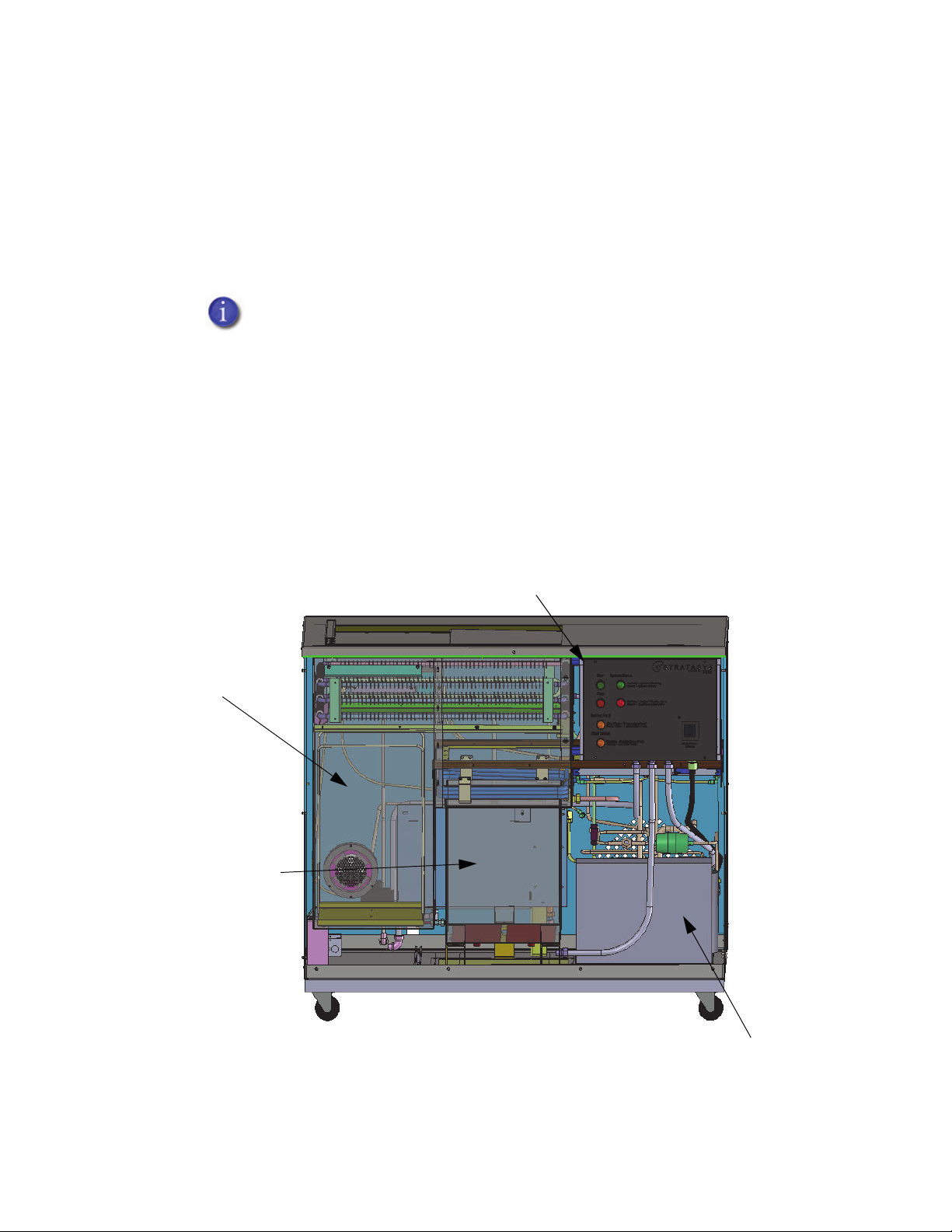
Cold/Dry Chamber
Cooling System
Smoothing Chamber
Front Panel
Programmable Logic
Controller (PLC)
(behind Front Panel)
Overview
The Stratasys Finishing Touch Smoothing Station is a proven method to
dramatically reduce, and in many cases eliminate the need for manual
post finishing. When used with a bead blaster burnishing station, FDM
ABS models can be finished to injection-molded quality in a short period
of time. See “Recommended Burnishing Process” on page3-17 for details.
Major components of the smoothing station includes the following:
• Smoothing Fluid Reservoir • Cooling/Heating System
• Water Separator • Front Panel
• Smoothing Chamber • Programmable Logic Controller (PLC)
When smoothing parts, it is important to remember that the better the
parts look before the smoothing process, the higher the quality of part
you will get after smoothing.
• Cold/Dry Chamber
Finishing Touch Smoothing Station User Guide 1-3
Figure 1-1: Major Components (Front View)
Page 10
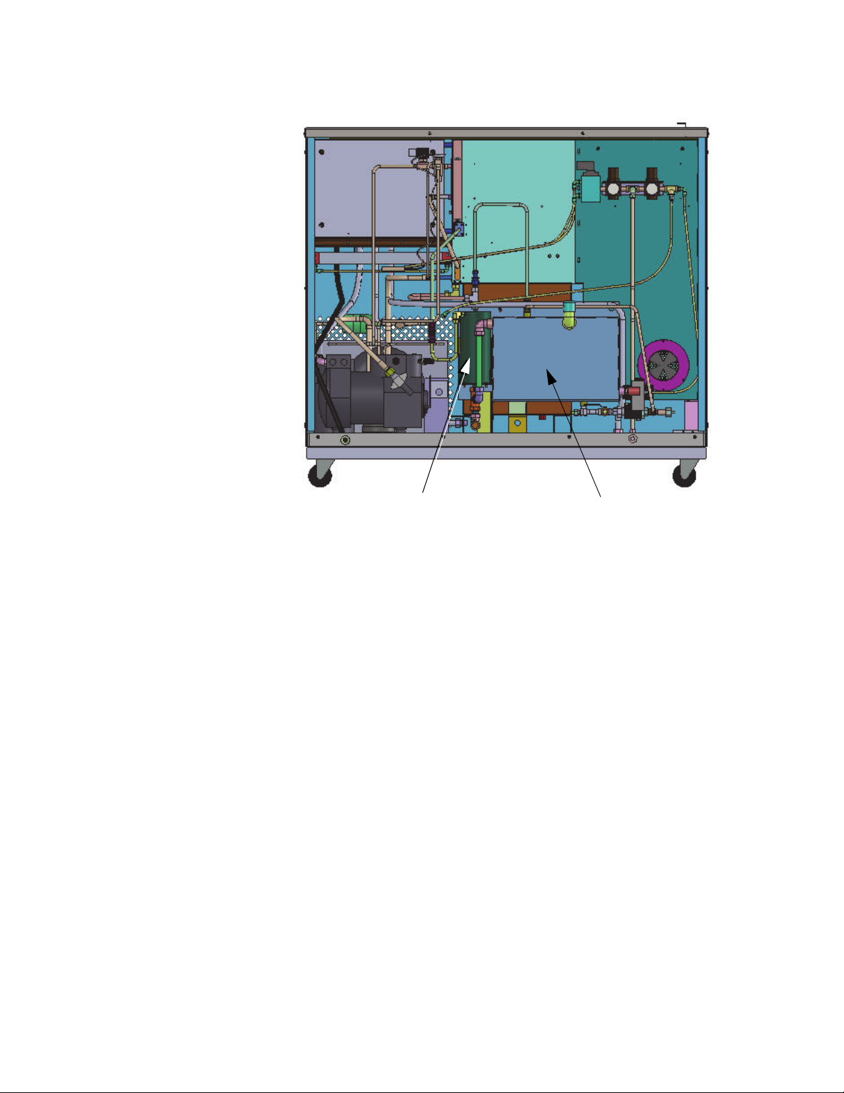
Smoothing Fluid Reservoir
Water Separator
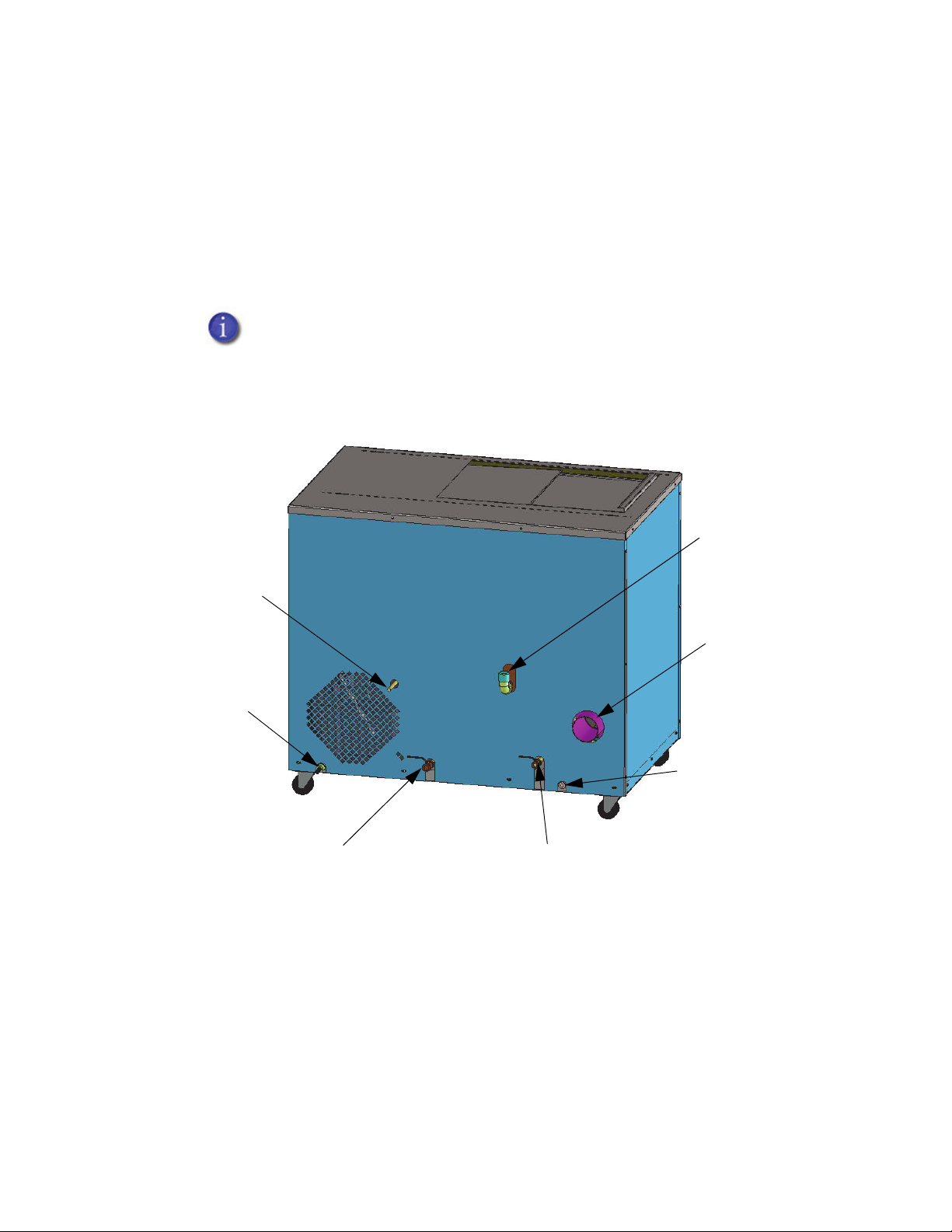
Figure 1-2: Major Components (Back View)
Smoothing Fluid Reservoir
Located in the back of the system, the smoothing fluid reservoir is a
7-gallon container that holds the smoothing solution. There is a low level
float inside the tank that indicates when it is time to add solution.
Water Separator
Located next to the smoothing fluid reservoir, the water separator
removes water from the smoothing solution. This occurs as the solution
enters the separator after being cycled through the smoothing chamber.
The separator works on the principle that the smoothing solution is
heavier than water and that the two will not mix with each other. The
lighter water floats on top of the solution and is siphoned off through the
P-trap over flow tube and into an external collection container. Follow
local guidelines and regulations concerning safety and disposal of
drained water.
1-4 Introduction
Page 11

Smoothing Chamber
The smoothing chamber is located under the smoothing lid and is where
parts are smoothed. The smoothing solution is heated from the bottom of
the chamber. Once hot, the vapor from the solution fills the chamber until
it is collected by the cooling coils at the top of the chamber. The collected
fluid is then recycled back into the separator and then into the smoothing
fluid reservoir.
Cold/Dry Chamber
The cold/dry camber is located next to the smoothing chamber. This
chamber provides hanging racks for parts that are drying or are cooling.
The manual sliding lid should be drawn closed across both the cold/dry
chamber and the smoothing chamber when not actively smoothing parts.
Keep this lid closed for safety and for cooling parts.
Front Panel
The front panel of the system contains all of the operator interface
switches and indicator lights. Located behind the panel is the main
electrical box.
Programmable Logic Controller (PLC)
Located in the main electrical box, the PLC controls the entire operation of
the system.
Figure 1-3: Programmable Logic Controller
Finishing Touch Smoothing Station User Guide 1-5
Page 12
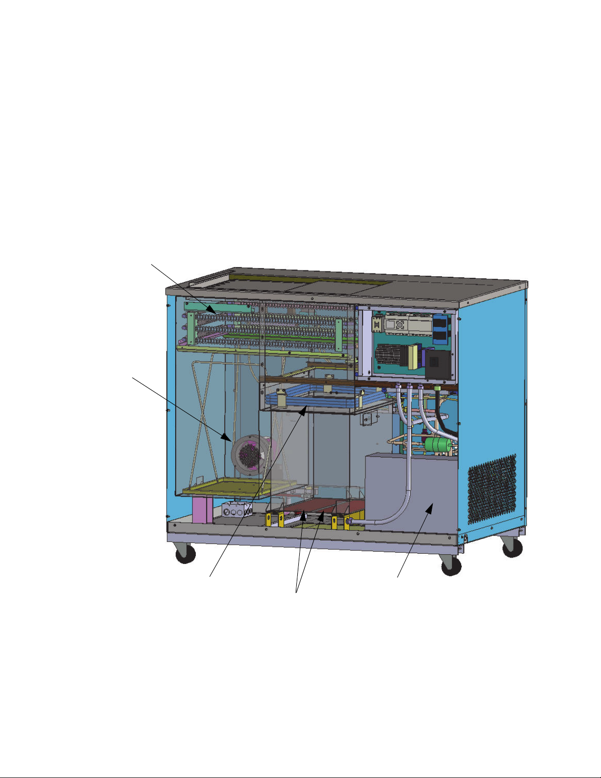
Compressor
Lower Primary Cooling Coils
Upper Fin Coils
Exhaust Fan
Heaters
Cooling/Heating System
The cooling/heating system is comprised of the following components:
• Compressor
• Lower Primary Cooling Coils
• Upper Fin Coils
• Exhaust Fan
• Heaters
Figure 1-4: Cooling/Heating System Components
1-6 Introduction
Page 13

Compressor
A ¾ horse semi-hermetic compressor cools the system. The vents on the
panels of the smoothing station must be kept free of obstructions to allow
for free air movement through the compressor.
Lower Primary Cooling Coils
These coils are located beneath the air driven smoothing chamber lid.
They create a cold air blanket over the top of the smoothing chamber. This
cold air blanket keeps the smoothing solution vapor contained within the
smoothing chamber. They also are the collection point for the smoothing
vapor as it is cooled as it changes back into a liquid for recycling back into
the smoothing fluid reservoir.
Upper Fin Coils
Located over both the smoothing chamber and the cool/dry chamber
these coils cool the surfaces of the parts prior to exposing them to the
vapor in the smoothing chamber. They also collect any smoothing
solution vapor that is out gassed during the drying process.
Exhaust Fan
Heaters
Foot Switch
Located at the bottom of the cool/dry chamber, the exhaust fan removes
any out gassed vapors collected in the chamber. The exhaust must be
directed to an unobstructed area that is located outside of the building.
The process works on the principle that the smoothing solution vapor is
approximately 4 times heavier than air. This causes the vapor to sink to
the bottom of the chamber.
The smoothing station has two temperature controlled silicon pad heaters
located on the bottom of the system. The temperature of the heaters are
factory set and should not be adjusted except by qualified service
personnel.
The foot switch, located on the floor, activates an air driven linear actuator
to open the lid covering the smoothing chamber. When the foot switch is
pressed, the PCL resets the over all timer on the system. If the switch is not
pressed within a four hour period, the system assumes that no activity has
taken place and goes into a shutdown mode.
Finishing Touch Smoothing Station User Guide 1-7
Page 14

On/Off
System Status Light
Start
Stop
System Fault
Fluid Status
Switch
Shut Down
Status Light
Button
Button
Light
Light
Panel Controls
The front panel controls of the smoothing station includes the following:
• On/Off Switch
• Start Button
• Stop Button
• Fluid Status Light
• System Fault Light
• System Status Light
• Shut Down Status Light
Figure 1-5: Front Panel Control Components
1-8 Introduction
Page 15

On/Off Switch
The main power breaker on/off switch activates power to the system.
Start Button
Pressing the momentary start switch activates the smoothing station
operation cycle. Once pressed, an internal timer automatically causes the
system to shutdown if the foot switch for the air activated smoothing lid
has not been pressed within a four hour time period.
Stop Button
The momentary stop button initiates the cycle shutdown procedure. The
smoothing station operation cycle can be restarted by pressing the start
button.
Once the stop button is pressed (or a four hour time period has elapsed
without the lid over the smoothing chamber being opened) the red
indicator light will begin flashing indicating that the system is in a
shutdown mode. When the shutdown cycle is complete, the red shutdown
light will remain in a steady on state. This indicates that the system has
shutdown.
Fluid Status Light
When this amber fluid status light is rapidly flashing, there is not enough
fluid is flowing into the vapor chamber. This condition also may indicate
that the fluid valve is not closing properly.
When the amber fluid status light is on steady, there is low fluid in the
storage container. Adding solution to the smoothing reservoir will cause
the light to turn off.
Finishing Touch Smoothing Station User Guide 1-9
Page 16

System Fault Light
The system fault light will illuminate indicating there is a fault in the
system. Refer to the “Troubleshooting Chart” on page4-4 for details.
System Status Light
When the system is ready to begin smoothing parts, the green system
status light will be illuminated. When the stop button is pressed, the light
will turn off.
Shut Down Status Light
Once the stop button is pressed (or four hours have elapsed without the
lid over the smoothing chamber being opened), the red shut down light
will begin flashing. The flashing indicates that the system is shutting
down. When the shutdown cycle is complete, the light will remain steady
on indicating that the system shutdown is complete.
1-10 Introduction
Page 17

Chapter 2: Safety
This chapter describes the Stratasys Finishing Touch Smoothing
Station general safety information along with environmental safety
and personal protection concerns.
Safety _______________________________________________________________ 2-2
Drain and Vent Smoothing Station Prior to Service ___________________ 2-2
Potential Health Effects ____________________________________________ 2-2
First Aid Measures__________________________________________________ 2-2
Inhalation _____________________________________________________ 2-2
Skin Contact___________________________________________________ 2-2
Eye Contact ___________________________________________________ 2-2
Ingestion ______________________________________________________ 2-2
Environmental Safety _________________________________________________ 2-3
Spill Clean Up _____________________________________________________ 2-3
Handling and Storage _____________________________________________ 2-3
Handling ______________________________________________________ 2-3
Storage _______________________________________________________ 2-3
Waste Disposal ____________________________________________________ 2-4
Personal Protection___________________________________________________ 2-4
Eye/Face Protection _______________________________________________ 2-4
Protective Clothing ________________________________________________ 2-4
Equipment Modification ___________________________________________ 2-4
Finishing Touch Smoothing Station User Guide 2-1
Page 18

Safety
Drain and Vent Smoothing Station Prior to Service
Under no circumstances should any smoothing solution be poured
on the ground or down a sewer drain. Always follow local guidelines
and regulations concerning the disposal of smoothing solution.
Allow the smoothing solution to cool before draining. Make sure that all
solution is drained from the smoothing chamber and the chamber is well
ventilated prior to performing any work in the chamber. This includes
cleaning the chamber.
Potential Health Effects
Read and understand the Material Safety Data Sheet (MSDS)
associated with the smoothing solution.
• Avoid inhaling vapors because dizziness and weakness can occur.
• Skin contact may cause severe irritation with burning, redness,
swelling, pain or rash.
• Eye contact may cause severe eye irritation with tearing, pain or
blurred vision.
• Do not ingestion any solutions associated with the smoothing station.
First Aid Measures
Inhalation
If inhaled, move to fresh air. If not breathing, give artificial respiration. If
breathing is difficult, give oxygen. Call a physician.
Skin Contact
Flush skin with water after contact. Wash contaminated clothing before
reuse.
Eye Contact
In case of contact, immediately flush eyes with plenty of water for at least
15 minutes. Call a physician.
Ingestion
If swallowed, do not induce vomiting. Immediately give two glasses of
water. Never give anything by mouth to an unconscious person. Call a
physician.
2-2 Safety
Page 19

Environmental Safety
Under no circumstances should any smoothing solution be poured
on the ground or down a sewer drain. Always follow local guidelines
and regulations concerning the disposal of smoothing solution.
Spill Clean Up
• Immediately evacuate the area and provide maximum ventilation,
especially in low places where heavy vapors might collect.
• Only personnel equipped with proper equipment should be permitted
in the area.
• Soak up with sawdust, sand, oil dry or other absorbent material.
• After all visible traces, including vapors, have been removed,
thoroughly wet vacuum the area.
• Do not flush solution into a sewer.
• If area of the spill is porous, remove as much contaminated earth and
gravel, etc. as necessary and place in closed containers for disposal.
• Consult the MSDS in case of an accidental spill and then proceed with
clean up accordingly.
Handling and Storage
Always follow directions printed on the outside of the container.
Handling
Do not inhale vapors emitted from the container. Avoid contact with eyes,
skin or clothing. Wash thoroughly after handling. Keep container tightly
closed.
Storage
Store solution in a clean and dry area. Do not allow stored product to
exceed 125° F (52° C) in temperature to prevent leakage or potential
rupture of container from pressure and expansion. Protect from freezing
temperatures. If the solvent is stored below 14° F (-10° C), mix prior to use.
Refer to the MSDS for specific details.
Finishing Touch Smoothing Station User Guide 2-3
Page 20

Waste Disposal
Under no circumstances should any smoothing solution be poured
on the ground or down a sewer drain. Always follow local guidelines
and regulations concerning the disposal of smoothing solution.
Treatment, storage, transportation, and disposal must be in accordance
with applicable Federal, State/Provincial, and local regulations.
Personal Protection
Use only with adequate ventilation. Vapors are heavier than air, posing a
hazard of asphyxia if they are trapped in enclosed or low places.
Eye/Face Protection
Wear safety glasses. Where splash potential exists, wear chemical splash
goggles.
Protective Clothing
Wear appropriate protective clothing and gloves to avoid potential skin
contact.
Equipment Modification
Protection provided by the equipment may be impaired if not used in the
manner specified in the instructions.
2-4 Safety
Page 21

Chapter 3: Installation and Setup
This chapter describes installation and setup procedures for the
Stratasys Finishing Touch Smoothing Station.
Site Requirements ____________________________________________________ 3-2
Space Requirements ______________________________________________ 3-2
Environmental Requirements _______________________________________ 3-2
Electrical Requirements ____________________________________________ 3-3
Compressed Air Requirements _____________________________________ 3-3
Exhaust Vent Requirements ________________________________________ 3-4
Consumables _____________________________________________________ 3-5
Smoothing Station Fluid ________________________________________ 3-5
Installing the System__________________________________________________ 3-6
Inspect Crate for Damage _________________________________________ 3-6
Required Tools and Equipment _____________________________________ 3-6
Forklift Truck Requirements _________________________________________ 3-6
Unpacking the System _____________________________________________ 3-7
Remove Shipping Crate ________________________________________ 3-7
System Connections _________________________________________________ 3-8
Filling the Reservoir _______________________________________________ 3-10
Power On Process ________________________________________________ 3-11
Power Off Process ________________________________________________ 3-11
Prior to Smoothing Parts ___________________________________________ 3-12
WaterWorks _________________________________________________________ 3-13
Support Material Removal ________________________________________ 3-13
Smoothing Operation _______________________________________________ 3-14
Masking__________________________________________________________ 3-15
Smoothing the Parts ______________________________________________ 3-15
Repeatability_____________________________________________________ 3-16
Post Finishing Tips _________________________________________________ 3-16
Post Finish Painting Tips ____________________________________________ 3-16
Recommended Burnishing Process ________________________________ 3-17
Effects of High Temperature _______________________________________ 3-17
Finishing Touch Smoothing Station User Guide 3-1
Page 22

Smoothing Station
(Top View)
Exhaust Vent
36 in. (91.44 cm) Clearance in
front of the Smoothing Station
24 in. (60.96 cm)
Clearance at the
back and on the sides
of the Smoothing Station
Site Requirements
Space Requirements
Allow 24 in. (60.96 cm) of clearance in the back of the system as well as on
both the left and right-hand sides. Allow 36 in. (91.44 cm) in the front. The
minimum ceiling height is 96 in. (243.84 cm) and the floor must be hard
and level.
The room must be well ventilated and allow for free flow of air exchange.
The exhaust air flow must not create a negative pressure. The system may
not establish a proper exhaust if a negative pressure condition exists.
Figure 1: System Space Requirements
Environmental Requirements
• The smoothing station is intended for indoor use only.
• Operating temperature: 60°F (15.6°C) to 85°F (26.7°C)
• Humidity: <65% non-condensing
3-2 Installation and Setup
Page 23

Electrical Requirements
The facility power is required to meet the following power quality and
nominal voltage requirements:
• 200-240 VAC
• 50/60 Hz
• Single phase
• 20 Amp (dedicated circuit)
Operation of the system outside this range is not recommended and may
degrade of the performance of the system.
A power plug is not supplied at the end of the power cord. Check
with local electrical ordinances for the size and plug configuration for
a 20 amp dedicated electrical circuit outlet.
Compressed Air Requirements
The system has an onboard pressure regulator and an onboard particle
filtration, water, and oil separation.
• Supply pressure at the system must be at least 5 SCFM at 80 psi
(minimum)
• Non-lubricated
• Non-condensing
• For serviceability, there should be at least one quick disconnect
installed so the system can be easily disconnected from the air supply.
• A flexible air hose should be used to allow for movement of the
machine.
The system is equipped with a threaded female fitting (dimensional ¼
NPT standard) for a compressed air connection. The user must supply the
necessary connections between the fitting and the customer’s compressed
air supply.
Finishing Touch Smoothing Station User Guide 3-3
Page 24

Outside Exhaust
Vent
Flexible Exhaust Hose
50 ft.
(15.24 m)
Max
Exhaust Vent Requirements
The system requires the installation of a 4-inch (101.5 mm) exhaust vent
(with screen) to the outside of the building.
• The exhaust vent should be properly located so the exhaust fumes will
not be directed back into the building. Keep the exhaust vent at least 6
ft. (
1.8 m) away from windows or near air intakes.
• The pipe from the vent should extend into the room at a minimum of
2-inches (50 mm) so a flexible exhaust hose can be attached later
(shipped with the system).
• The room must allow for free flow of air exchange so exhaust air from
the system does not create a negative pressure. The exhaust system
may not perform properly if a negative pressure exists.
A maximum of 50 ft. (15.24 m) of rigid smooth walled hose is allowed
between the system exhaust hose and the exhaust vent. Keep 90°
bends to a minimum to ensure adequate air flow at exit. Do not
exceed more than 270° worth of bends.
Figure 2: Flexible Exhaust Hose
3-4 Installation and Setup
Page 25

Consumables
Smoothing Station Fluid
It is recommended that a minimum of two 5-gallon containers of
Smoothing Station Fluid be available at the time of installation.
Product name: SSF - Microcare SSF, Smoothing Station Fluid (part number
MCC-SSF0IP) can be ordered from the following company:
www.SmoothingFluids.com
MicroCare Corp.
595 John Downey Drive
New Britain, CT 06051
United States of America
Phone: 860.827.0626 or 800.638.0125
techsupport@microcare.com
MicroCare Europe bvba
Erasmuslaan 10
B-1804 Cargovil (Zemst) Belgium
Phone: 00 +32 2 251 95 05
techsupport@microcare.com
Randall Oliveiro, Marketing Director
Uniwes Technology (S) Pte Ltd
102E Pasir Panjang Road #03-01/02
Citilink Warehouse Complex
Singapore, 118529
randall_oliveiro@uniwes.com.sg
Phone: 011-65-6275-8183
Finishing Touch Smoothing Station User Guide 3-5
Page 26
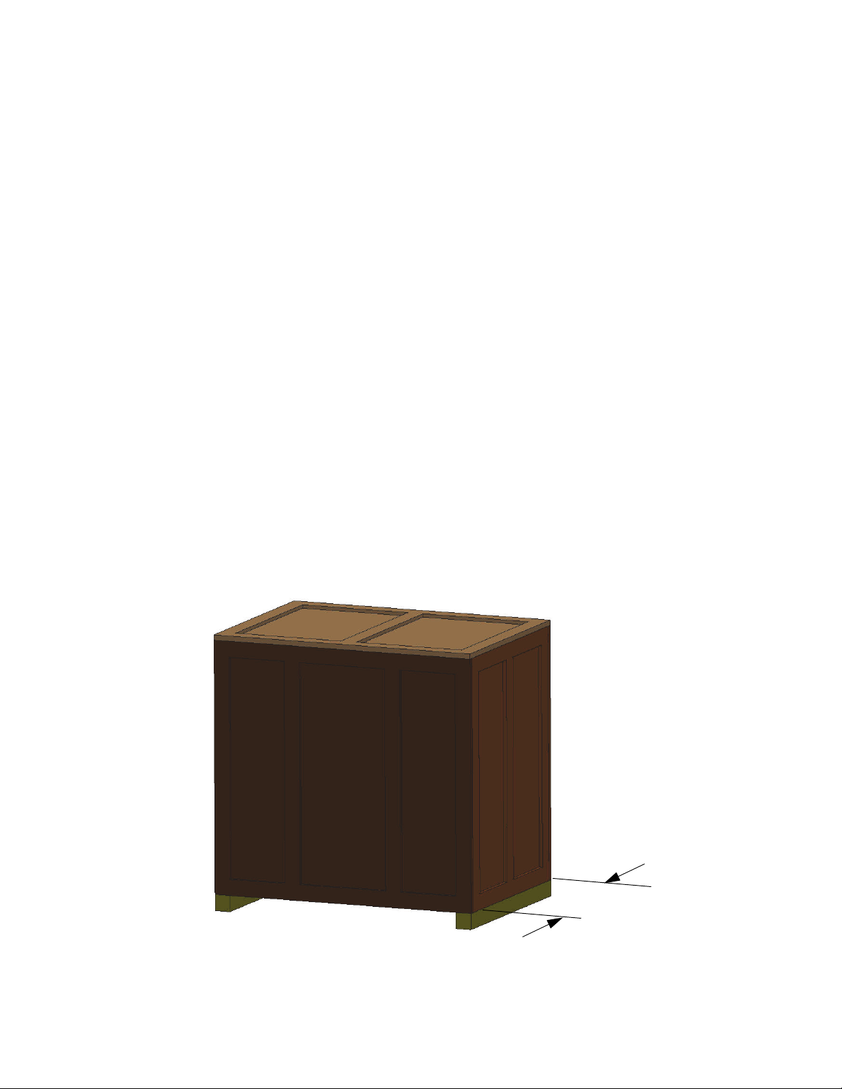
46.0 in.
(116.84 cm)
Installing the System
Inspect Crate for Damage
Before opening the shipping crate, inspect the crate for signs of exterior
damage.
Report evidence of excessive damage to Stratasys and the shipping
company.
Required Tools and Equipment
• Basic hand tools (powered screwdriver or drill with phillips bit).
• Forklift truck of sufficient size to raise the system from the shipping
skid.
Forklift Truck Requirements
The smoothing station is heavy and requires a forklift truck with the
following minimum capabilities:
• Ability to lift a crated system of 600 lbs. (272.16 kg).
• The forks on the forklift truck must be at least 46.0 inches (116.84 cm)
long to fit under the of the skid of the crated system.
Figure 3: Forklift Length
3-6 Installation and Setup
Page 27

To p
Runner Boards
Back
Base Shipping Board
2X
Unpacking the System
Remove Shipping Crate
Caution: Wear safety glasses when removing the system from the
shipping crate
Figure 4: Unpacking the System
Screws that are to be removed are highlighted with red paint.
1. Unscrew and remove the back and top of the shipping crate.
2. Unscrew and remove the two runner boards from the top of the crate.
3. Unscrew and remove the base shipping board that holds the system in
the crate
4. Use a forklift truck to lift the system from the shipping skid.
5. Carefully remove the plastic wrap from the system.
Caution: Use care when removing the plastic wrap to avoid
scratching the system surfaces.
6. Inspect the system exterior for dents and scratches. Immediately
report any damage to Stratasys and the shipping company.
Finishing Touch Smoothing Station User Guide 3-7
Page 28
Storage Tank Drain
Water Separator Drain
Exhaust Port
Fill Tube
Power Cord
Water
Overflow
Compressed Air
System Connections
Perform the following steps to connect the smoothing station:
1. Position the smoothing station in the desired location. Make sure there
is adequate room in the back and on the sides of the smoothing
station. The air vents can not be blocked and must allow for free
airflow.
Use Teflon tape on all fittings for an airtight seal.
2. Attach a compressed air fitting (customer supplied) to the compressed
air fitting on the back of the system. Connect the air supply to the
fitting.
Figure 5: Smoothing Station Connections
3. Locate and verify that both the storage tank drain and the water
separator drain valves are closed.
4. Connect one end of the flexible 4-inch (10.16 cm) exhaust hose to the
exhaust port on the back of the system. Connect the other end of the
hose to the outside exhaust vent.
3-8 Installation and Setup
Page 29

5. Locate the plastic carboy container and plastic tube in the accessory
kit. Fill the carboy container with 1 inch (2.54 cm) of water and place
behind the system. Place one end of the tube over the end of the water
overflow drain and insert the other end of the tube into the carboy
container. Make sure the hose is touching the bottom of the container.
6. Connect the power cord to the electrical supply.
7. Refer to the Finishing Touch Smoothing Station User Guide CD
located in the accessory kit for instructions on how to smooth parts.
Finishing Touch Smoothing Station User Guide 3-9
Page 30

Filling the Reservoir
Only transfer smoothing solution from the bulk container to the
smoothing fluid reservoir in a well-ventilated area.
Always wear safety goggles and observe proper safety procedures
when transferring smoothing solution. Read and understand the
MSDS associated with smoothing solution.
Perform the following steps when filling the fluid reservoir with
smoothing solution:
1. Locate the bung wrench, faucet, plastic pail and funnel in the
accessory kit.
2. Remove the fill cap on the fill tube on the smoothing station.
3. Insert the funnel into the fill tube.
4. Remove the finishing solution from its shipping container.
5. Using a small pliers remove the safety cover over the 2-inch (5.08 cm)
bung opening.
6. Assembly the faucet provided in the accessory kit by screwing
together.
7. Use the bung wrench to remove the 2-inch (5.08 cm) bung cap from
the storage can.
8. Screw the faucet into the opening.
9. Place the storage container at an elevation above the bucket.
10. Rotate the container so that the faucet is pointing down toward the
bucket.
11. Open the faucet and fill the bucket ¾ full. Shut off the faucet.
12. Pour the contents of the bucket into the funnel use caution not to over
flow the funnel.
13. Repeat steps 10 and 11 until the storage container is empty, or the
smoothing station storage tank is full.
14. Replace the cap on fill tube of the smoothing station.
15. Remove the faucet from the storage container.
16. Replace the 2-inch (5.08 cm) bung cap on the container to retain the
remaining solvent, or dispose of the container according to local
regulations.
3-10 Installation and Setup
Page 31

Power On Process
1. Turn the On/Off switch on to start the smoothing station.
2. The following action will start when the Cycle Start button is pressed:
• The refrigeration compressor will start.
• The cooling fan will turn on for 2-minutes and then will cycle
automatically.
• The air activated ball valve will open and start metering
smoothing solution to the smoothing chamber.
• After the solution is metered in the chamber, the heaters will turn
on.
• The green Ready light will illuminate and flash during warm-up
(approximately 5 minutes).
3. The smoothing station will warm up in approximately 10 minute.
The entire system is controlled by an over all timer. The timer will
begin the shutdown sequence if the air driven door over the
smoothing chamber is not opened at a minimum of every four hours.
Power Off Process
After all the parts are finished, press the stop button. The system will
begin the shutdown process. This process includes:
• The red light begins to flash indicating that the system has begun the
power down process.
• The ball valve controlling the amount of smoothing solution in the
chamber is clamped shut so that no more solution is allowed in the
chamber.
• The system will continue to heat the solution until it is has all
evaporated and distilled on the cooling coils and been recycled back
into the smoothing solution container.
• The heaters shut off.
• The refrigeration compressor shuts off.
• The red light stops flashing and stays on steady to indicate that the
shutdown is complete (approximately 1 hour in duration).
Finishing Touch Smoothing Station User Guide 3-11
Page 32

Prior to Smoothing Parts
The process for smoothing parts begins first with the building of the part.
The better the file preparation, orientation, system set up ,and tip
condition, the better the part will look after being processed by smoothing
station.
In general, the better the part at the start, the higher the quality at the end
of the smoothing process.
3-12 Installation and Setup
Page 33

WaterWorks
Support Material Removal
Use the following information when removing support material from
parts using WaterWorks™:
• Replace WaterWorks solution that has a low pH or is discolored and
full of support material. Low solution pH will increase the amount of
time necessary to remove support material. Parts can also become
stained from using dirty solution.
• Parts must be rinsed free of any WaterWorks solution. If there is any
dried on WaterWorks solution left on the part, the surface may blister
when exposed to the smoothing solution. Make sure that the rinse
water is clean and changed frequently. Agitation of the parts in the
rinse water will help remove any WaterWorks solution.
• Sparsely filled built parts can fill with WaterWorks solution during the
support removal process. All cavities must be free of WaterWorks
solution and completely dry. Pre filling the parts with clean water
prior to putting them in the WaterWorks tanks can help to avoid
absorbing WaterWorks solution into the parts. When possible, avoid
using sparse filled parts in the surface smoothing process.
• Completely dry parts prior to using the smoothing station. After the
parts are dry, inspect the surfaces that faced down during the drying
process. If there is evidence of a powdery residue from the
WaterWorks solution, rinse and dry the parts again before using the
smoothing station.
Finishing Touch Smoothing Station User Guide 3-13
Page 34

Smoothing Operation
The following information should be use to inspect parts prior to
smoothing:
• Inspect the part for build flaws, imbedded supports, or missing
geometry.
• Using your judgement lightly sand areas that could use some work
prior to utilizing the surface smoothing process. This may include
over sized seams, errant geometry blips etc. Do not spend a lot of time
pre-sanding.
• Do not use any type of cyanoacrylate glues (Super Glue) or epoxies on
parts prior to surface smoothing. The smoothing solution will dissolve
the glue. If a part needs repair prior to smoothing use a solvent
bonding process with solvents such as Weld-On®.
• Look for the best orientation to suspend the part. The parts should be
suspended so that it does not collect the smoothing solution while
being exposed. When solution is collected on or in a part, it is referred
to as “cupping”. This can cause damage to the part.
• Suspending the part once the orientation is determined. Look for a
suspension place on the part. Holes or cavities work well. If the part
does not have an obvious place to suspend if from, try one of the
following methods:
• Drill a small hole in the part so that the end of the suspension
hanger can be inserted into the hole. After the process is done, a
light sanding of the area with a small amount of glue will hide the
hole.
• Drill a 0.040-inch (0.102 cm) hole in or through the part. If possible
drill in a non-critical surface. Suspend the part from the hole. After
the process is done, drill the hole to 0.070-inch (0.178 cm) and
using a solvent bonding agent, insert a small piece of the same
color filament into the hole. Sand the filament smooth to the
surface.
It is advantageous to rotate some parts to different hanging points for
each exposure. If this is desired, plan ahead and locate the
appropriate number of hanging points.
3-14 Installation and Setup
Page 35

Masking
If desired, small holes and other features can be masked so the smoothing
solution does not effect them. This can be accomplished by applying a
water based masking material (modeling clay). This water-soluble
material can be pressed into any hole or over a feature and then removed
after the smoothing process.
Smoothing the Parts
The following information is important when smoothing parts in the
smoothing station:
• Suspend the part(s) in the cool/dry chamber of the smoothing station.
Allow the surface of the part to cool. This usually takes 10 to 15
minutes. The cooler the surface of the part, the better the reaction of
the smoothing solution is on the part.
• After cooling the part, open the smoothing chamber sliding door by
pressing on the foot switch. Use a slow deliberate decent, suspend the
part in the smoothing chamber so that the part is below the cooling
coils making sure not to touch the bottom or sides. Allow the part to
be exposed for 20 to 30 seconds. You should notice that the smoothing
solution collects on the part and begins to drip off. Once the dripping
has slowed or stopped, the smoothing process is complete. Lift the
part above the lower cooling coils and allow any remaining solution to
drip back into the smoothing chamber. Place the part back into the
cool/dry chamber. Release the foot switch, closing the smoothing
chamber lid, and then slide the top lid closed. Allow the part to cool/
dry for 10 to 15 minutes.
Do not lower or raise the part out of the smoothing chamber
rapidly. This will disturb the cold air blanket and allow smoothing
vapor to escape and be exhausted to the outside.
Do not lift the part above the top of the smoothing chamber. This
will allow solution fumes into the room.
• Repeated exposures of thin walled parts can cause warping or other
distortion. If the part has been exposed multiple times it is better to
allow it to dry over night and then inspect for additional exposure
needs.
• Once the part is smoothed leave the part in the cool dry rack
overnight. The parts will be dry to the touch in minutes, but it takes
several hours to fully cure.
Finishing Touch Smoothing Station User Guide 3-15
Page 36

Repeatability
The smoothing station has repeatable smoothing performance from part
to part. Once the process has been established and constantly repeated, all
parts will exhibit the same conformity.
Post Finishing Tips
• Inspect the part and if necessary, light sanding can be done on the
part. Sanding and smoothing can be done several times to obtain the
desired finish. Over smoothing and over sanding should be avoided.
• Cyanoacrylate (Super Glue®) glues can be used to join or repair
defects in parts.
• Thin walled parts should not exceed two smoothing cycles to avoid
warping the part.
• Place the part in the bead blaster (using recommended beads) and
using a sweeping motion 3 to 4 inches (7.62 cm to 10.16 cm) from the
part, burnish the entire part giving it a satin luster finish.
• Remove any masking by either picking it off, or placing the part in
luke warm water to dissolve it.
Post Finish Painting Tips
• Bead blasting is not required for parts that are going to be painted,
investment cast, or electroplated.
• Apply a coat of sand-able primer suitable for plastic to the part.
• The finish with colored ABS will diminish when burnishing. Spray
with a flat acrylic to bring back the color after burnishing.
• If necessary, apply smoothing putties (such as white putty from
Squadron products) to small areas. Allow the putty to dry so it can be
sanded to create a smooth finish.
• Wet sand primer to desired finish if required.
• Finish with a good quality spray paint suitable for use over plastic.
3-16 Installation and Setup
Page 37

Recommended Burnishing Process
Burnishing gives your parts an even smoother appearance and a matte
finish. Although this step is optional, it is recommended when a near
injection molded look is desired.
To prep your part for burnishing, first smooth your part using the
Smoothing Station, then lightly sand it. Smooth and sand your part again,
then smooth it a third time.
For burnishing, sand blasters (sometimes called bead blasters) are
available at tool supply stores. Choose one with the following
specifications:
• No > 30 psi or 2.068 bar at the spray nozzle
• Envelope size 1016 x 509 x 508 mm (40 x 22 x 20 in)
Stratasys recommends POLYHARD Type III bead media for burnishing
inside the sand blaster. Specify 20/30 bead screen size (0.841-0.595 mm or
0.0331- 0.0234 inches).
Order online at www.ustechnology.com/stratasys.
Effects of High Temperature
Parts that have been processed through the smoothing station should not
be subjected to high temperatures. This will cause the surface of the part
to expand more rapidly than the core of the part and blisters will result.
Finishing Touch Smoothing Station User Guide 3-17
Page 38

3-18 Installation and Setup
Page 39

Chapter 4: Troubleshooting
This chapter provides troubleshooting information for the
Stratasys Finishing Touch Smoothing Station.
Troubleshooting ______________________________________________________ 4-2
Frequently Asked Questions________________________________________ 4-2
System Will Not Start When the Cycle Start Button is Pressed ______ 4-2
Refrigeration Not Cooling or Does Not Have Inadequate Cooling 4-2
Excessive Frost or Ice on the Fin Coils ___________________________ 4-2
Smoothing Chamber Does Not Have Vapor or Vapor is Falling ___ 4-3
Troubleshooting Chart _____________________________________________ 4-4
Status Lights ___________________________________________________ 4-4
Ordering Supplies_____________________________________________________ 4-5
Smoothing Station Fluid ________________________________________ 4-5
Finishing Touch Smoothing Station User Guide 4-1
Page 40

Troubleshooting
Internal components of the smoothing station are powered by high
voltage. Improper servicing can cause electric shock. Only qualified
service personnel should service the smoothing station.
Frequently Asked Questions
System Will Not Start When the Cycle Start Button is Pressed
• Turn on the main power switch.
• Cycle start switch was pressed too quickly. The smoothing station will
not start until the PCL has come up. This takes a few seconds. Press
the button again.
• System not connected to a power source, or the power source breaker
is tripped.
• System circuit breaker is tripped.
Refrigeration Not Cooling or Does Not Have Inadequate Cooling
• The system is low on refrigerant. There is potentially a leak in the
refrigeration system. Contact your service representative. Only
qualified refrigeration personnel can inspect or repair the refrigeration
system, and replenish the coolant. Make sure that the coolant put into
the system matches the type indicated on the compressor.
Excessive Frost or Ice on the Fin Coils
• Excessive frost or ice on the coils can cause an insulation effect on the
coils. This can raise the temperature of the cold air blanket.
• Excessive frosting of the coils is defined by the finned coils being
frosted to the point of not being able to see the fins.
• Frost and ice on the coils are caused by humidity (Water) in the air.
Excessive humidity may not be able to be controlled by the
refrigeration defrost. If this is the case the system needs to be moved
to an area with less humidity (air-conditioned).
4-2 Troubleshooting
Page 41

Smoothing Chamber Does Not Have Vapor or Vapor is Falling
• Make sure the system is allowed to recover and stabilize the fluids
before preceding.
• The system in a shutdown mode. Check to see if the red light is
flashing or on steady.
• This system not heating properly. Internal heaters are high voltage.
Only qualified service personnel should attempt to service or replace
these heaters.
• Smoothing solution is contaminated with too much water. Excessive
moisture on the coils can cause the water separator to over flow into
the fluid storage container. If this happens repeatability water can
build up to the point that there is very little solvent in the system. In
this case drain the fluid storage tank and the water separator.
Replenish the tank with new solvent. Dispose of the drained water
properly according to local regulations.
Finishing Touch Smoothing Station User Guide 4-3
Page 42

Troubleshooting Chart
Use the troubleshooting charts below to diagnose errors in the smoothing
station.
Status Lights
System
Status
(Green)
Flashing System is warning up.
Steady System is in ready to smooth parts.
Steady Low fluid in storage container.
Rapid
Rapid
Rapid
Flashing
Shut Down
Status
(Red)
Flashing System is shutting down. This is normal
Steady Shutdown of system is complete. This is
Flashing
Slow
System
Fault
(Amber)
Slow
Flashing
Flashing
Fluid
Status
(Amber) Error Condition
operation.
normal operation.
Replenish the fluid for normal
operation.
Fluid fault - Not enough fluid flow into
Flashing
High temperature condition (HTC). The
Unsafe vapor condition (SVC). Vapor
the vapor chamber, or the fluid valve is
not closing.
thermocouple from controller too hot.
level are too high in the system.
Restart
Method
Press Start
button
Press Start
button
Press Start
button
Cycle
breaker
Cycle
breaker
Rapid
Flashing
Rapid
Flashing
4-4 Troubleshooting
Rapid
Rapid
Flashing
Flashing
Refrigeration high pressure switch
open.
Refrigeration low pressure switch open. Cycle
Cycle
breaker
breaker
Page 43

Ordering Supplies
• USE ONLY MicroCare SSF as the smoothing station fluid. This
product can be ordered from your local MicroCare distributor. Use of
any other solution will void the warranty and is used at the user’s own
risk.
• Order two pails for the initial install of the system, and then usually
one pail at a time after that.
• The solution will last quite a while in the smoothing station, but the
amount of use and parts smoothed will determine actual usage.
• Read and under stand the MSDS information for the product. Follow
precautions as described in the MSDS.
Smoothing Station Fluid
Product name: SSF - Microcare SSF, Smoothing Station Fluid (part number
MCC-SSF0IP) can be ordered from the following company:
www.SmoothingFluids.com
MicroCare Corp.
595 John Downey Drive
New Britain, CT 06051
United States of America
Phone: 860.827.0626 or 800.638.0125
techsupport@microcare.com
MicroCare Europe bvba
Erasmuslaan 10
B-1804 Cargovil (Zemst) Belgium
Phone: 00 +32 2 251 95 05
techsupport@microcare.com
Randall Oliveiro, Marketing Director
Uniwes Technology (S) Pte Ltd
102E Pasir Panjang Road #03-01/02
Citilink Warehouse Complex
Singapore, 118529
randall_oliveiro@uniwes.com.sg
Phone: 011-65-6275-8183
Finishing Touch Smoothing Station User Guide 4-5
Page 44

4-6 Troubleshooting
Page 45

Chapter 5: Supplemental Information
This chapter contains the Stratasys Finishing Touch Smoothing
Station Limited Warranty Statement.
Stratasys Limited Warranty Statement
Stratasys Limited Warranty and Limitation of Liability
Stratasys, Inc. ("Stratasys") warrants its FINISHING TOUCHTM SMOOTHING STATION systems and
associated peripheral devices and replacement parts (collectively, the "Product") purchased from Stratasys
or an Authorized Stratasys Reseller to be free from defects in material and workmanship according to the
terms and conditions stated below:
Warranties extend only to the original purchaser of the Product. The warranty on the original Product, as
delivered, extends for one year starting on the date of delivery. Your sole remedy as purchaser under this
Limited Warranty shall be repair or replacement as provided herein.
To preserve your warranty rights, all FINISHING TOUCH SMOOTHING STATION Products must be installed
in accordance with the then-current User Guide available at www.stratasys.com. During the Limited
Warranty period, Stratasys or its designated representative will, at their option, repair or replace a defective
Product as set forth below. Service Parts and replacement Products will be furnished on an exchange basis,
and will be either new or refurbished. All replaced parts or replaced Products become the property of
Stratasys, and you will be invoiced for replacement parts if defective parts are not returned as directed by
Stratasys under this Limited Warranty.
Stratasys will bear the cost of returned parts, as well as for shipping new or rebuilt replacement parts to you,
provided that you report the warranty claim within the Limited Warranty period and obtain return instructions
from Stratasys prior to return. Replacement parts independently carry a 90-day warranty from date of
shipment from Stratasys or designated representative location. Consumable parts are not covered by this
Limited Warranty. Warranty services may be provided by Stratasys, an Authorized Reseller, or a third party
service provider designated by Stratasys.
No coverage or benefits under this Limited Warranty will exist if any of the following conditions apply:
(a) The FINISHING TOUCH SMOOTHING STATION Product has been subjected to abnormal use,
improper or inadequate maintenance, unauthorized modifications, unauthorized repair, misuse, abuse,
exposure to moisture, flooding, fire, electrical problems associated with incoming power, or other acts which
are not the fault of Stratasys, Inc.
(b) Stratasys' Customer Service Department was not notified of the defect or malfunction of the
FINISHING TOUCH SMOOTHING STATION system prior to expiration of the one-year warranty period.
Finishing Touch Smoothing Station User Guide 5-1
Page 46

(c) Parts or consumables were installed and used that were not certified or approved by Stratasys.
Stratasys approves only the solution sold under the name SSF-Microcare SSF as the smoothing station fluid to
be used in the FINISHING TOUCH SMOOTHING STATION Product. Use of any other solution will void the
warranty and is used at the user’s own risk.
Stratasys will not be liable under any circumstances for Product replacement or associated labor, part
replacement, loss of use, loss of profits, or for any other indirect, incidental, collateral, exemplary, punitive,
consequential or special damages, losses or injuries arising out of the use of any solvent not approved by
Stratasys as the fluid in the FINISHING TOUCH SMOOTHING STATION Product. Stratasys reserves the
right to refuse to furnish service or to warranty replacement parts on a FINISHING TOUCH SMOOTHING
STATION Product in which an unauthorized solvent was used.
Stratasys will also not be liable under any circumstances for Product replacement or associated labor, loss of
use, loss of profits, or for any other indirect, incidental, collateral, exemplary, punitive, consequential or
special damages, or losses arising out of the purchase of the FINISHING TOUCH SMOOTHING STATION
Products and/or out of this limited warranty, even if Stratasys or its designated representative have been
advised of the possibility of such damages or claims. To the extent such claims are not excludable as
adjudged by a court of competent jurisdiction; you agree to accept as sole and exclusive remedy, a
payment equal to the original purchase price for the product adjudged to be defective.
SOME COUNTRIES, REGIONS, STATES OR PROVINCES DO NOT ALLOW THE EXCLUSION OR
LIMITATION OF REMEDIES OR OF INCIDENTAL, PUNITIVE, OR CONSEQUENTIAL DAMAGES, OR THE
APPLICABLE TIME PERIODS, SO THE ABOVE LIMITATIONS OR EXCLUSIONS MAY NOT APPLY TO YOU.
EXCEPT TO THE EXTENT LAWFULLY PERMITTED, THIS LIMITED WARRANTY DOES NOT EXCLUDE,
RESTRICT OR MODIFY, AND IS IN ADDITION TO THE STATUTORY RIGHTS APPLICABLE TO THE SALE OF
THIS PRODUCT TO YOU.
This warranty gives you specific legal rights and you might also have other rights that vary from country/
region to country/region, state to state, or province to province.
EXCEPT FOR THIS LIMITED WARRANTY, AND TO THE FULLEST EXTENT ALLOWED BY LAW, NEITHER
STRATASYS NOR ANY AUTHORIZED RESELLER MAKES ANY OTHER WARRANTY OF ANY KIND,
EXPRESS OR IMPLIED, INCLUDING ANY IMPLIED WARRANTY OF MERCHANTABILITY OR FITNESS FOR A
PARTICULAR PURPOSE. STRATASYS DOES NOT OFFER, ASSUME OR AUTHORIZE THE OFFER OR
ASSUMPTION OF LIABILITY FOR IT OR FOR ANY OTHER WARRANTY, EITHER EXPRESS OR IMPLIED BY
ANY AUTHORIZED RESELLER OR OTHER INDEPENDENT THIRD PARTY.
5-2 Supplemental Information
 Loading...