

Page 1

Part No. 401691-0001_REV_D
F123 Series
Shared Office 3D Printers
USER GUIDE
Page 2

LIABILITY STATEMENT
The information in this document is subject to change without notice. Stratasys, Inc. shall
not be liable for errors contained herein or for incidental or consequential damages in
connection with the furnishing, performance, or use of this material. Stratasys, Inc. makes
no warranty of any kind with regard to this material, including, but not limited to, the implied
warranties of merchantability and fitness for a particular purpose. It is the responsibility of
the system owner/material buyer to determine that the Stratasys material is safe, lawful,
and technically suitable for the intended application as well as identify the proper disposal
(or recycling) method consistent with local environmental regulations. Except as provided in
Stratasys' standard conditions of sale, Stratasys shall not be responsible for any loss
resulting from any use of its products described herein.
COPYRIGHT STATEMENT
This document is protected by copyright. All rights reserved. Its use, disclosure, and possession are
restricted by an agreement with Stratasys per software copyright. No part of this document may be
photocopied, reproduced or translated into another language without the prior written consent of Stratasys,
Inc.
All drawings and information herein are the property of Stratasys Inc. All unauthorized use and reproduction
is prohibited.
TRADEMARK ACKNOWLEDGMENTS
Stratasys, F123 Series, F170, F270, F370, GrabCAD, Insight and FDM are trademarks of Stratasys Ltd.
and/or subsidiaries or affiliates and may be registered in certain jurisdictions. All other product names and
trademarks are the property of their respective owners.
ii
Page 3

ABOUT THE F123 SERIES PRINTERS
The Stratasys F123 Series 3D printers incorporate the latest in innovative technology to
provide you with precise prototypes from a CAD design. Stratasys’ Fused Deposition
Modeling (FDM) technology provides prototype parts, including internal features, that can
be used to field-test form, fit, and function. Direct Digital Manufacturing (DDM) allows for the
creation of customized end-use parts straight from 3D CAD data. The F123 Series printers
feature a servo/belt driven XY gantry with multiple modeling material capability.
COMPONENTS
• The F123 Series Printer
• Material Package(s)
• Welcome Kit (containing documentation on how to download your user guide and common tools for
maintaining the printer)
• GrabCAD Print Software Package
• A Computer Workstation (not sold by Stratasys)
F170 HIGHLIGHTS
• Envelope Size: 10 x 10 x 10 inch (254 x 254 x 254 mm)
• Material Bays: 1 model, 1 support
• Touchscreen Graphical User Interface
• Wi-Fi capabilities
• Three USB ports (2 in front, 1 in back)
• Camera for remote monitoring
F270 HIGHLIGHTS
• Envelope Size: 12 x 10 x 12 inch (308 x 254 x 308 mm)
• Material Bays: 2 model, 2 support
• Touchscreen Graphical User Interface
• Auto changeover capabilities
• Wi-Fi capabilities
• Three USB ports (2 in front, 1 in back)
• Camera for remote monitoring
F370 HIGHLIGHTS
• Envelope Size: 14 x 10 x 14 inch (356 x 254 x 356 mm)
• Material Bays: 2 model, 2 support
• Insight Software Package
• Touchscreen Graphical User Interface
• Auto changeover capabilities
• Wi-Fi capabilities
• Three USB ports (2 in front, 1 in back)
• Camera for remote monitoring
iii
Page 4

ABOUT THIS GUIDE
This guide is your introduction to building prototypes and end-use parts using a Stratasys
3D production, rapid prototype system. It is designed as a learning and reference tool that
explains system operation in an easy to understand, step-by-step, process.
HOW TO USE THIS GUIDE
This guide is divided into easy-to-follow chapters. You can read this guide chapter by
chapter or use the Table of Contents when you need to quickly find specific information.
Keeping this guide close to your printer will efficiently allow you to troubleshoot and
maintain the printer.
CONVENTIONS USED IN THIS GUIDE
The following conventions are used in this guide:
• When you see text in this font, it indicates a button being pressed via the User Interface touchscreen.
For example, press the Queue
• When you see text in blue, it indicates that the text is a linked reference to a specific figure, table,
heading, or page number.
• Standard bold text is used to emphasize items within instructional sequences or indicate a
navigational path you must follow to locate/start a software application, open or save a file on your
workstation PC, or perform an operation when working with GrabCAD Print. The > character is used
to separate items within a navigational path. For example, navigate to File > Open from the Main
Menu.
button within the Navigation Menu.
REVISION LOG
0.
Revision Date Description of Changes
A January 2017 First release of this document
B February 2017 Updated manual tip calibration procedure
C April 2017 Updated Troubleshooting chapter, Warnings and Errors
D December 2017 Updated User Interface, troubleshooting, and procedures
iv
Page 5

TABLE OF CONTENTS
1 SERVICE AND SUPPORT ................................................................... 1
SERVICE.................................................................................................................................... 1
SOFTWARE SUPPORT............................................................................................................. 1
SAFETY INSTRUCTIONS ......................................................................................................... 2
Hazard Types .................................................................................................................................................... 2
Product Safety Signs ......................................................................................................................................... 2
Product Safety Label Locations......................................................................................................................... 3
Potential Safety Hazard Areas........................................................................................................................... 5
Door Locks......................................................................................................................................................... 6
General Safety Practices................................................................................................................................... 6
Environmental Requirements ............................................................................................................................ 6
2 PRINTER SETUP .................................................................................7
GENERAL INFORMATION ........................................................................................................ 7
Welcome Kit Contents ....................................................................................................................................... 7
BASIC SETUP.......................................................................................................................... 11
Stabilizing the Printer....................................................................................................................................... 11
Identifying Your Printer .................................................................................................................................... 12
Making the Network Connection...................................................................................................................... 13
Connecting the Power Cable........................................................................................................................... 13
Configuring the Network .................................................................................................................................. 14
Installing GrabCAD Print.................................................................................................................................. 19
Connecting to the F123 Series Printer............................................................................................................. 19
Setting the Printer’s Date and Time................................................................................................................. 19
Updating the Controller software Version........................................................................................................ 19
Adjusting the Tip Wipe Height ......................................................................................................................... 19
3 SYSTEM COMPONENTS ..................................................................20
PRINTER OVERVIEW ............................................................................................................. 20
Access Doors and Panels................................................................................................................................ 20
Interface Panel................................................................................................................................................. 22
OVEN COMPONENTS ............................................................................................................ 23
v
Page 6

Oven Door ....................................................................................................................................................... 23
Oven Light ....................................................................................................................................................... 25
Platen .............................................................................................................................................................. 26
Tip Wipe Assemblies ....................................................................................................................................... 27
Purge Chute .................................................................................................................................................... 28
MATERIAL BAY DRAWER COMPONENTS ........................................................................... 29
Material Bays................................................................................................................................................... 29
Material Drive Controller.................................................................................................................................. 30
Storage Drawer ............................................................................................................................................... 31
GANTRY .................................................................................................................................. 32
Print Heads...................................................................................................................................................... 33
MODELING MATERIALS......................................................................................................... 34
Materials Used ................................................................................................................................................ 34
Material Spool Memory Chip ........................................................................................................................... 35
Tips and Slice Height....................................................................................................................................... 36
SOFTWARE............................................................................................................................. 37
Controller Software.......................................................................................................................................... 37
GrabCAD Print Software ................................................................................................................................. 37
Insight Software............................................................................................................................................... 37
4 USER INTERFACE ............................................................................ 38
OVERVIEW.............................................................................................................................. 38
Navigation Menu.............................................................................................................................................. 39
Display Area .................................................................................................................................................... 40
WORKING WITH THE BUILD PAGE....................................................................................... 40
Loading a File .................................................................................................................................................. 41
Viewing Print Job Information.......................................................................................................................... 45
Build Status Display......................................................................................................................................... 46
Print Job Controls ............................................................................................................................................ 48
WORKING WITH THE QUEUE PAGE..................................................................................... 50
Adding a Job to the Job Queue ....................................................................................................................... 51
Editing the Job Queue ..................................................................................................................................... 55
Viewing Job Details ......................................................................................................................................... 57
About the Sample Queue ................................................................................................................................ 59
WORKING WITH THE MATERIALS PAGE ............................................................................. 60
Head Status Icons ........................................................................................................................................... 61
Viewing Head Details ...................................................................................................................................... 63
Material Status Icons ....................................................................................................................................... 66
Viewing Material Details .................................................................................................................................. 69
Material Load Controls .................................................................................................................................... 70
vi
Page 7

WORKING WITH THE TOOLS PAGE ..................................................................................... 76
Tools Page Menu ............................................................................................................................................ 77
Navigation Overview........................................................................................................................................ 78
Settings............................................................................................................................................................ 79
Calibration ....................................................................................................................................................... 89
Maintenance.................................................................................................................................................... 91
Network ........................................................................................................................................................... 95
Power ............................................................................................................................................................ 101
Light............................................................................................................................................................... 104
5 OPERATING THE PRINTER ........................................................... 105
BASIC USER OPERATIONS................................................................................................. 105
Powering ON the Printer................................................................................................................................ 105
Powering OFF the Printer.............................................................................................................................. 107
LOADING MATERIAL ............................................................................................................ 108
Material Spool Preparation ............................................................................................................................ 108
Material Spool Installation ............................................................................................................................. 109
UNLOADING MATERIAL ...................................................................................................... 113
Removing Material Spools............................................................................................................................. 114
Material Auto Changeover............................................................................................................................. 115
Handling/Storing Materials ............................................................................................................................ 116
HEAD REPLACEMENT ......................................................................................................... 117
Replacing a Standard Head .......................................................................................................................... 117
Replacing a PLA Head .................................................................................................................................. 119
BASIC JOB BUILD TASKS .................................................................................................... 120
Before a Build ................................................................................................................................................ 120
Preparing the Printer ..................................................................................................................................... 120
Selecting a Job to Build ................................................................................................................................. 122
Information Available During a Build ............................................................................................................. 123
Build Warnings .............................................................................................................................................. 124
Pausing a Build.............................................................................................................................................. 125
Aborting a Build ............................................................................................................................................. 126
After a Build is Complete ............................................................................................................................... 128
CHANGING PRINTER DEFAULTS ....................................................................................... 130
Job Storage ................................................................................................................................................... 130
Part Build Location ........................................................................................................................................ 131
Display Units.................................................................................................................................................. 132
Oven Temperature Control............................................................................................................................ 134
Touchscreen Display Brightness ................................................................................................................... 134
Display Language.......................................................................................................................................... 135
PRINTER STATUS ................................................................................................................ 136
vii
Page 8

Head Odometer Status.................................................................................................................................. 136
Materials Status............................................................................................................................................. 136
Temperature Status....................................................................................................................................... 138
Software Version ........................................................................................................................................... 139
6 CALIBRATION AND ADJUSTMENTS ............................................. 140
TIP CALIBRATION................................................................................................................. 141
Automatic Tip Calibration .............................................................................................................................. 142
Manual Tip Calibration................................................................................................................................... 144
TOUCHSCREEN CALIBRATION........................................................................................... 154
XY GANTRY CALIBRATION.................................................................................................. 156
Z ZERO CALIBRATION ......................................................................................................... 156
TIP WIPE HEIGHT ADJUSTMENT........................................................................................ 157
7 MAINTENANCE ............................................................................... 158
UPDATING CONTROLLER SOFTWARE.............................................................................. 158
GrabCAD Print Method.................................................................................................................................. 158
Insight Software Method................................................................................................................................ 158
EXPORTING SYSTEM CONFIGURATION (.CFG) FILE....................................................... 162
MAINTENANCE SCHEDULE................................................................................................. 163
WEEKLY MAINTENANCE ..................................................................................................... 164
Cleaning the Oven Chamber ......................................................................................................................... 164
Cleaning the Platen ....................................................................................................................................... 164
MONTHLY MAINTENANCE................................................................................................... 165
Clean/Inspect Tip Wipe Assemblies .............................................................................................................. 165
AS NEEDED MAINTENANCE ............................................................................................... 167
Cleaning the Exterior Surface of the Printer .................................................................................................. 167
Cleaning the Touchscreen Display................................................................................................................ 167
Inspecting and cleaning the tip shields.......................................................................................................... 167
Cleaning the Oven Door glass Surfaces ....................................................................................................... 168
CUSTOMER REPLACEABLE UNITS.................................................................................... 169
Powering Off.................................................................................................................................................. 169
Rear Panel..................................................................................................................................................... 170
Right and Left Side Panels ............................................................................................................................ 171
Front Top Cover ............................................................................................................................................ 173
Rear Top Cover ............................................................................................................................................. 174
viii
Page 9

3.3/5/12 VDC ATX Power Supply.................................................................................................................. 175
Oven Thermistor............................................................................................................................................ 176
Material Bays................................................................................................................................................. 177
Replacing a Head .......................................................................................................................................... 180
Head Ribbon Cables ..................................................................................................................................... 181
Touchscreen Display ..................................................................................................................................... 184
Right and Left Side Oven Blowers................................................................................................................. 186
Oven Door Gasket......................................................................................................................................... 188
Z Drive Belt.................................................................................................................................................... 189
Y Bellows....................................................................................................................................................... 191
Oven Light ..................................................................................................................................................... 193
Oven Door Camera ....................................................................................................................................... 195
Oven Door Latch ........................................................................................................................................... 197
Y Blocks......................................................................................................................................................... 200
Top Cover Interlock Sensor and Actuator ..................................................................................................... 202
8 TROUBLESHOOTING ..................................................................... 204
GETTING HELP..................................................................................................................... 204
WARNINGS AND ERRORS................................................................................................... 205
Warnings at Build Start.................................................................................................................................. 205
Errors Preventing a Build from Starting ......................................................................................................... 207
Load/Unload Errors ....................................................................................................................................... 210
Build Pause Warnings ................................................................................................................................... 212
Build Abort Errors .......................................................................................................................................... 214
Head Warnings.............................................................................................................................................. 216
Head Errors ................................................................................................................................................... 216
FINDING A REMEDY............................................................................................................. 217
9 SUPPLEMENTARY INFO ................................................................. 219
DECLARATION OF CONFORMITY....................................................................................... 219
REGULATORY AND ENVIRONMENTAL INFORMATION.................................................... 219
EMC Class A Warning .................................................................................................................................. 219
FCC Statements (U.S.A.) .............................................................................................................................. 219
Canada Electromagnetic compatibility (EMC) ............................................................................................... 220
MSDS (Material Safety Data Sheet).............................................................................................................. 220
Disposal of waste equipment by users in private households in the European Union .................................. 220
ix
Page 10

1 SERVICE AND SUPPORT
This chapter provides information on service and support for the F123 Series as well as safety information and
safety label locations.
SERVICE
If you have a problem with your printer that is not covered in this guide, please contact Stratasys Customer
Support. Contact information is available from the Stratasys website at: http://www.stratasys.com/customer-
support/contact-customer-support.
When calling in for service, always have your printer’s software version (see “Software Version” on page 139)
and hardware serial number available (see “Identifying Your Printer” on page 12). You may also need access to
GrabCAD Print to provide a configuration file from your hardware (see “Exporting System Configuration (.CFG)
File” on page 162).
SOFTWARE SUPPORT
If you have a software problem that is not covered in this guide, please contact Stratasys Customer Support.
Contact information is available from the Stratasys website at: http://www.stratasys.com/customer-support/
contact-customer-support.
When calling in for service, always have your printer’s software version (see “Software Version” on page 139)
and printer serial number available (see “Identifying Your Printer” on page 12). You may also need access to
GrabCAD Print to provide a configuration file from your hardware (see “Exporting System Configuration (.CFG)
File” on page 162).
1
Page 11

SAFETY INSTRUCTIONS
The following basic safety tips are given to ensure safe installation, operation, and maintenance of Stratasys
equipment and are not to be considered as comprehensive on matters of safety. The F123 Series printers are
designed to be safe and reliable rapid prototyping printers. Access to areas of the printer are potentially
dangerous.
HAZARD TYPES
Stratasys recommends that all services be performed by qualified personnel. All personnel working on or
around the printer should be knowledgeable of what the following hazard classifications mean throughout this
guide.
• Warnings and Cautions precede the paragraph to which they pertain.
Warning: Indicates a potentially hazardous situation which, if not avoided, may
result in injury or death.
Caution: Indicates a situation which, if not avoided, could result in damage to
equipment.
• Notes follow the relative paragraph.
Note: Indicates additional information relative to the current topic.
PRODUCT SAFETY SIGNS
Note: Always read and adhere to safety statements, and be aware of the
following safety signs when you see them on the printer.
Stratasys makes every effort to ensure that our printers are safe and reliable at all times. However, there will be
times when you must access areas of the printer where potentially high voltages, hot temperatures, and/or
moving mechanical components could cause severe injury.
High Voltage: The high voltage sign indicates the presence of high voltages.
Always stay away from any exposed electrical circuitry. It is recommended that
all jewelry be removed.
Hot Surface: The hot surface sign indicates the presence of devices with high
temperatures. Always use extra care when working around heated components.
Always wear the safety gloves provided in the Welcome Kit.
Gloves: The gloves sign indicates that if you enter the area specified by the
symbol you must wear safety gloves (provided in the Welcome Kit) which have
been approved for high temperatures.
2
Page 12

Crushed Hand: The crushed hand sign indicates that a hazard exists where you
could get your hand crushed between two objects. One or more objects move in
the area that you are working.
PRODUCT SAFETY LABEL LOCATIONS
Figure 1-1: Oven safety label locations
3
Page 13
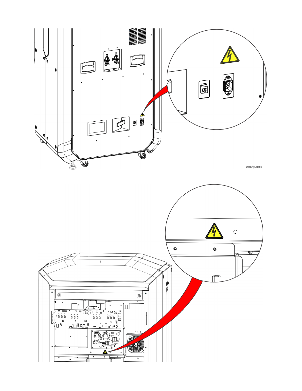
Figure 1-2: Rear panel safety label locations
Figure 1-3: Electrical panel safety label locations
4
Page 14

POTENTIAL SAFETY HAZARD AREAS
The following components and areas of the printer are highlighted as potential safety hazards that may cause
system failure or reliability problems if proper safety procedures are not followed.
OVEN
Warning: Always wear safety gloves and long sleeves when working inside the
oven. Components are hot.
Note: Opening the oven door shuts the oven heaters off.
GANTRY
Warning: Never wear a tie, loose clothing or dangling jewelry when working
around moving components of the printer.
Beneath the top cover of the printer is the gantry. This area houses the
mechanical drive components of the X and Y axes. Use extreme caution
whenever accessing this area of the printer.
Z STAGE
Note: The printer’s servo motors are disabled when the oven door and/or top
cover are open. The XY pinch hazard between the timing belts and pulleys is
minimized by locking the oven door and top cover while building and disabling
the motors when the oven door and top cover are open. The oven door and top
cover automatically lock when the printer is building and cannot be opened
while the printer is building. You cannot start a build if the oven door or top
cover are open.
Warning: Never wear a tie, loose clothing or dangling jewelry when working
around moving components of the printer.
The drive belt, pulleys and Z stage servo motor can cause severe injury. The Z
stage crushing hazard is minimized by locking the oven door during Z stage
moves and disabling the Z motor when the oven door is open.
5
Page 15

DOOR LOCKS
Interlock switches are used to communicate the status of the oven door and the top cover to the printer. For
safety reasons, the oven door and top cover must be closed before the X, Y, and Z motors will operate.
GENERAL SAFETY PRACTICES
Abide by these general safety practices when working with this printer.
High Voltage: High voltage is present in the printer.
Warning: Only use an OSHA or CE approved step stool when accessing the
area under the top cover of the printer.
Warning: Always wear safety gloves and long sleeves when working inside the
oven. Components are hot.
ENVIRONMENTAL REQUIREMENTS
• The F123 Series printer is for indoor use only.
• Air quality conditions with excessive solid particulates (conductive or non-conductive) may
result in system damage.
• Air quality conditions in which airborne oils are allowed to accumulate on or within the printer
can damage the plastic components.
• System operating temperature shall be in the range of 59°F to 86°F (15°C to 30°C), with
relative humidity range of 30% to 70% non-condensing.
• System storage temperature shall be in the range of 32°F to 95°F (0°C to 35°C), with relative
humidity range of 20% to 90% non-condensing.
• Altitude shall not exceed 6561.68 feet (2000 m).
• Material storage shall be in the range of 55°F to 86°F (13°C to 30°C), with relative humidity less
than 70%.
• Noise emission (acoustic):
• <32dBA when idle
• <46dBA when building
6
Page 16

2 PRINTER SETUP
1
2
3
4
OR
US Cable
This chapter describes basic setup of the F123 Series.
GENERAL INFORMATION
WELCOME KIT CONTENTS
The printer’s Welcome Kit contains the Welcome Insert document and common tools you will need to maintain
the printer. Use the following figures and tables to identify the contents of the Welcome Kit.
Figure 2-1: Welcome Kit Contents - Documents and Cables
Euro Cable
Table 2-1: Key for Figure 2-1
Welcome Insert
1
Document
RJ45 Cable This cable is used to establish a network connection between the F123 Series printer and
2
3 USB Flash Drive The printer features 3 USB ports (see Figure 3-3 on page 22 for port locations). As an
4 AC Cable (US or
Euro)
Contains instructions for downloading the F123 Series User Guide (this document).
your Ethernet network. See “Making the Network Connection” on page 13.
alternate method to sending job files to the printer via GrabCAD Print, this flash drive can
be used to store processed job files which you build frequently (see “Adding a Job to the
Job Queue” on page 51).
This cable provides the power connection to the printer. See “Connecting the Power
Cable” on page 13. When connecting the cable, select the cable appropriate for your
location (US cable or Euro cable).
7
Page 17

Figure 2-2: Welcome Kit Contents - Tools
1
2
3
4
5
6
Table 2-2: Key for Figure 2-2
Leather
1
Safety
Gloves
2 Needle
Nose Pliers
(extra slim)
3 Needle
Nose Pliers
1
/8)
(7
4 5” Cutters These are used to cut a material spool’s filament when unloading and removing materials from the
5 Loupe
Magnifier
6 Scraper This tool is used to scrape parts or material off the substrate.
Printer components may be extremely hot. To prevent burns or other injuries, these gloves should
be worn any time you see the gloves safety sign throughout this document. See “Product Safety
Signs” on page 2.
Occasionally, you may need to use pliers to aid in the clearing of debris which have accumulated
on the head and/or tips (see “Clean/Inspect Tip Wipe Assemblies” on page 165).
Occasionally, you may need to use pliers to aid in the clearing of debris which have accumulated
on the head and/or tips (see “Clean/Inspect Tip Wipe Assemblies” on page 165).
printer. See “Unloading Material” on page 113.
This tool is included to aid you with performing a Manual Tip Calibration which requires you to view
small toolpath relationships. See “Manual Tip Calibration” on page 144.
8
Page 18

Figure 2-3: Welcome Kit Contents - Cleaning Supplies & Storage Materials
1
2
3
Table 2-3: Key for Figure 2-4
Touchscreen
1
Cleaning Kit
2 Microfiber Cloth Various components of the printer may become dirty and occasionally need to be cleaned.
3 Resealable Bag (x6) When unloaded, non-empty model and support material spools should be stored within these
From repeated use, the touchscreen may become dirty and occasionally need to be cleaned.
Only use suitable LCD cleaning agents when cleaning the touchscreen. See “Cleaning the
Touchscreen Display” on page 167 for cleaning instructions.
Only use a suitable microfiber cloth to clean these components. See “Cleaning the Exterior
Surface of the Printer” on page 167 for cleaning instructions using this cloth.
bags to prevent moisture from contacting the spool’s filament (see “Handling/Storing
Materials” on page 116).
9
Page 19

Figure 2-4: Additional Components - Startup Materials
1
2-4
5
6
The following items are not located within the Welcome Kit. Instead, they can be found within the oven chamber
and the storage drawer. The items found within the oven chamber must be removed before powering the printer
ON.
Table 2-4: Key for Figure 2-4
1 Substrate (x16) A substrate is the surface upon which a part is built. The same substrate is used for all model materials,
2 ABS Model Material
3 QSR Support
4 PLA Material Spool
5 PLA Model Head Print head for use with PLA model material only (see “Print Heads” on page 33).
6 PLA Cooling Module Cooling module to be used in conjunction with the PLA model head (see “Print Heads” on page 33).
including PLA. See “Preparing the Printer” on page 120 for more information.
Material spool containing 60 in
Spool
Material spool containing 60 in
Material Spool
Material spool containing 60 in
3
(984 cc) of ABS model material (see “Materials Used” on page 34).
3
(984 cc) of QSR support material (see “Materials Used” on page 34).
3
(984 cc) of PLA material (see “Materials Used” on page 34).
10
Page 20

BASIC SETUP
Jackscrew
Locknut
Follow the Site Preparation Guide to ensure that your facility is effectively and safely prepared for printer
installation. Do not proceed with the following sections until the “Unpacking the Printer” section of the Site
Preparation Guide has been completed. When installation is complete, perform the following setup tasks.
• Verify that the startup materials have been removed from the oven chamber. If not, remove these
items. See “Additional Components - Startup Materials” on page 10 for details on the startup
materials.
• Open the top cover and ensure that the orange clip has been removed from the X belt, and the
orange tie wrap has been removed from the X motor. If not, remove the orange clip and/or orange tie
wrap securing these components.
STABILIZING THE PRINTER
Caution: The stability pads are used to stabilize the printer after it has been
moved to its desired operating location. The stability pads must be set prior to
printer operation.
To stabilize the printer:
1. Roll the printer to its desired operating location and verify that minimum space requirements
have been met.
Side Clearance Minimum 4 inches (10.16 cm) on each side
Rear Clearance Minimum 6 inches (15.24 cm)
Front Clearance Minimum 20 inches (50.80 cm)
Overhead Clearance Minimum 20 inches (50.80 cm)
2. Thread the stability pad jackscrew downward until the stability pad makes contact with the floor
(see Figure 2-5).
3. Turn the jackscrew an additional 1-2 turns downward and set the locknut firmly against the lower
frame member (see Figure 2-5).
Note: Ideally, each caster wheel will remain in slight contact with the floor and
using minimal force, be able to be rotated.
4. Repeat step 2 and step 3 to set all remaining stability pads.
Figure 2-5: Stability Pad Jackscrew Adjustment
11
Page 21

IDENTIFYING YOUR PRINTER
Serial Number Tag
Use the following tags to identify your printer:
• Serial Number Tag - Refer to this number when requesting service. You can also locate the printer’s
serial number via the Maintenance page of the User Interface (see “Serial Number” on page 94 for
more information).
• Model Tag - The printer’s model number, part number and power requirements are given on this tag.
This tag also lists all patent numbers associated with the printer, some FCC compliance information,
voltage warnings, and the Stratasys web address.
Both tags are located on the back side of the printer near the bottom, and are typically placed near the printer’s
power connection. Use the information on these tags when identifying your printer with Customer Support.
Figure 2-6: ID Tag Locations
12
Page 22

MAKING THE NETWORK CONNECTION
Ethernet Network
Power Cable
Connection
Processed job files can be transferred from GrabCAD Print to the F123 Series printer through your facility’s
Ethernet network. An RJ45 network connector is located on the right, rear corner of the printer (as viewed from
the rear). See Figure 2-7 for the network connection location.
Note: A 15 foot (4‘.6m) network patch cable is supplied with the printer and
located in the welcome kit. Facilities having network connection points
further from the printer than can be reached by the supplied cable are
responsible for the procurement of an appropriate cable.
CONNECTING THE POWER CABLE
To connect the power cable:
1. Connect the male end of the supplied power cord (US or Euro) directly into a grounded electrical
outlet.
2. Connect the female end of the power cord directly into the socket located on the back of the
printer (see Figure 2-7).
Warning: The power cord serves as the disconnect device. The socket outlet
must be easily accessible.
Figure 2-7: Rear Connections
13
Page 23

CONFIGURING THE NETWORK
This section is provided in case you need to change your network settings. Within the Network page you can set
your printer’s address type to Static, Dynamic (DHCP), or Wi-Fi; Dynamic is selected by default.
• Static address - you must enter an IP address, subnet mask, and gateway address for the printer
(provided by the system administrator). Once entered, the address will not change.
• Dynamic address (DHCP) - a network server or PC will generate an IP address for the printer. A
different IP address may be generated from time to time by the server or PC.
• Wi-Fi address - the printer will scan for and allow you to connect to an available Wi-Fi network (if the
Wi-Fi dongle has been installed).
NETWORK ADDRESS CONFIGURATION
To configure your printer’s network address settings:
1. Power ON the printer, see “Powering ON the Printer” on page 105.
2. Open the Tools page by pressing the To ol s button within the Navigation Menu (see Table 4-1 on
page 39).
3. Open the Network page by pressing the Network button within the Tools page (see Figure 4-34
on page 76).
4. The Connection Type row allows you to select between a wired or wireless network. The option
selected will determine the configurable settings displayed within the Network page.
• Selecting the Wired option will allow you to select between a Dynamic or Static network mode.
• Selecting the Wireless option will configure the pinter to use a Wi-Fi network. You will need to scan
for a wireless network and enter the security settings for the selected network (if required) to
complete the configuration. Please note that the availability of the Wireless option depends upon the
configuration purchased with your printer.
5. After selecting the radio button corresponding to the connection type you’d like to use (wired or
wireless) press the Back button in the upper-left corner of the page to return to the Network page.
6. For wired networks:
A. The Network Mode row will be displayed. Press anywhere within this row.
B. Select either the Static or Dynamic radio button to enable that network address type.
Depending on the option selected, you may need to configure additional information within
the Network page.
Figure 2-8: Wired Network Selection
14
Page 24

• If the Static option is enabled, you must manually configure the IP Address, Subnet Mask, and
Gateway Address fields.To configure this information simply touch a field on the screen to select
it and then use the keypad displayed to enter address information.
• Touch anywhere on the screen outside of the keypad to exit and close the keypad.
Figure 2-9: Static Network Configuration
• Scroll to the bottom of the page and press the Apply button when finished to save the
network configuration.
• Press the Back button in the upper-left corner of the page to return to the Network page.
Figure 2-10: Apply Changes Button
15
Page 25

• If the Dynamic option is enabled, no additional configuration is necessary as a network server or
PC will automatically generate an IP address for the printer. A different IP address may be
generated from time to time by the server or PC; the generated IP address will be displayed
within the IP Address field of the Network page, and corresponding Subnet Mask and Gateway
Address information will also be displayed.
• Press the Back button to exit the page and return to the Tools page.
Figure 2-11: Dynamic Network Configuration
7. For wireless networks:
A. The Available Networks row will be displayed (Wi-Fi dongle must be installed). Press
anywhere within this row.
B. Press the Scan button; the printer will scan for an available wireless (Wi-Fi) network.
16
Page 26

Figure 2-12: Scan for Wireless Network
C. A list of available networks will be displayed; select the wireless network you’d like to
connect to by pressing anywhere within the row.
D. A page will be displayed containing the details of the selected Wi-Fi network. Within this
page use the keyboard to enter the password and/or username required to connect to the
network.
Figure 2-13: Enter Wi-Fi Network Information
17
Page 27

E. When finished, touch anywhere on the screen outside of the keypad to exit and close the
keypad.
F. Scroll to the bottom of the page and press the Connect button to save the network
configuration.
Figure 2-14: Connect Button
G. Press the Back button to exit the page and return to the Network page. The name of the
selected wireless network will be displayed within the Available Networks row.
H. Press the Back button to exit the page and return to the Tools page. The Network button will
refresh and a blue indicator will be displayed indicating that the printer is configured for a
Wi-Fi network.
Figure 2-15: Enter Network Settings Dialog
18
Page 28

INSTALLING GRABCAD PRINT
Install the GrabCAD Print software on a facility workstation. Navigate to http://help.grabcad.com/article/197-
sign-up-download-and-install and follow the on-screen instructions.
CONNECTING TO THE F123 SERIES PRINTER
Add the F123 Series printer to the GrabCAD Print application. Navigate to http://help.grabcad.com/article/198-
connect-your-printers and follow the on-screen instructions.
SETTING THE PRINTER’S DATE AND TIME
In order to ensure accurate build times, the printer’s clock must be set correctly. If you find that your printer’s
date and/or time are incorrect you can update them using GrabCAD Print. To do so, navigate to
http://help.grabcad.com/article/196-printer-firmware-management and follow the procedure for “Changing your
printer’s clock time”.
UPDATING THE CONTROLLER SOFTWARE VERSION
Update the Controller Software if necessary. See “Updating Controller Software” on page 158.
ADJUSTING THE TIP WIPE HEIGHT
If necessary, adjust the tip wipe height. See “Tip Wipe Height Adjustment” on page 157.
19
Page 29
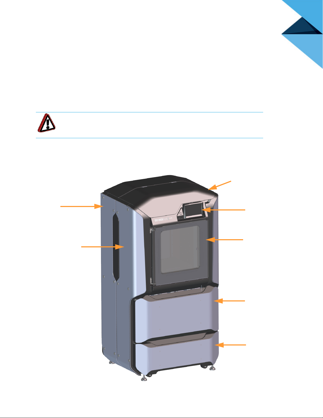
3 SYSTEM COMPONENTS
To p C o ve r
Material
Bay
Drawer
Oven Door
Interface Panel
Front Side Panel
(left & right)
Storage
Drawer
Rear Side Panel
(left & right)
This chapter describes the components of the F123 Series. Information regarding the materials and tips that
can be used by the printer is also included in this chapter.
PRINTER OVERVIEW
ACCESS DOORS AND PANELS
Warning: Do not energize when the rear panel is not secured in place.
This printer has been designed to allow easy access to the most frequently accessed areas on the system.
Doors and panels are highlighted in Figure 3-1 and Figure 3-2.
Figure 3-1: Access Doors and Panels - Front View
20
Page 30

Figure 3-2: Access Doors and Panels - Rear View
Rear Panel
TOP COVER
Allows access to the gantry and head assemblies.
OVEN DOOR
Allows access to the platen, tip wipe assemblies, purge area, and completed parts for removal. The printer’s
camera is also housed within the oven door.
MATERIAL BAY DRAWER
Allows access to the material bay components (material bays, material spools, and the material drive
controllers).
STORAGE DRAWER
Provides a built-in area which can be used for miscellaneous storage of spare parts, tools, etc., as needed.
RIGHT & LEFT SIDE PANELS
The right and left side panels provide access to the oven chamber fans.
REAR PANEL
The rear panel provides access to the electronics bay.
21
Page 31

INTERFACE PANEL
Touchscreen
User Interface
Power Button
Front USB Ports, 1 Additional in Rear
The interface panel houses the printer’s touchscreen user interface, power button, and USB ports.
Figure 3-3: Interface Panel
TOUCHSCREEN USER INTERFACE
Allows for user control of the printer. From the User Interface you can access various screens to select jobs for
building, control jobs in the process of being built, change materials, perform calibrations, and configure your
printer’s settings and maintenance options. The touchscreen visually displays the operational state of the printer
as well as any warning information available.
See “4 User Interface” on page 38 for detailed information on the components and pages of the User Interface.
POWER BUTTON
Allows you to power the printer ON and OFF (see “Powering ON the Printer” on page 105 and “Powering OFF
the Printer” on page 107 more information).
USB PORTS
The printer’s USB ports allow you to easily upload job files to be built. After plugging a USB flash drive into any
of the USB ports you can access the flash drive’s contents via the Queue page (see “Working with the Queue
Page” on page 50 for details).
22
Page 32

OVEN COMPONENTS
Tip Wipe
Assemblies
(model left,
support right)
Platen
Oven Door
Camera
Oven
Light
Purge
Chute
Oven
Door
Gasket
The oven consists of the oven door and everything that you see through the oven door window, including the
platen, tip wipe assemblies, purge chute, and oven heaters. The printer’s camera is housed within the frame of
the oven door.
Figure 3-4: Oven Components
OVEN DOOR
The oven door (see Figure 3-4) utilizes an electromagnetic lock along with optical sensors. The oven door
remains locked while the printer is building and automatically unlocks when it is safe for you to access the
components of the oven. You cannot open the oven door when the printer is building. The top cover will
automatically unlock in conjunction with the oven door, allowing you to manually open the top cover. The oven
door must be open prior to opening the top cover. The oven door gasket, which runs around the perimeter of the
oven door frame, helps to provide an airtight seal when the oven door is closed.
The oven door window is composed of 2 panes of tempered glass.
23
Page 33

CAMERA
The printer’s camera is housed within the frame of the oven door and provides remote monitoring capabilities
while a part is building. Using the GrabCAD Print application installed on your workstation PC, you can view the
part as it is building allowing you to remotely monitor part build quality. Pictures are automatically taken at a set
interval via GrabCAD Print. Please note that the camera image displayed will include some reflection as a result
of the oven door’s glass.
Figure 3-5: Camera Location
24
Page 34

OVEN LIGHT
Oven Light
A single light pipe is mounted on the front upper edge of the oven and is used to illuminate the oven chamber
(Figure 3-6). The light pipe consists of nine high-temperature LEDs; each LED is rated at 1-watt. The oven light
is powered by 12 VDC.
The Light button within the Tools page indicates the current state of the oven light and allows you to manually
turn the light ON of OFF (see “Light” on page 104).
Figure 3-6: Oven Light Location
25
Page 35

PLATEN
Platen
Tip Offset
Calibration
Targets
The steel platen provides the level surface on which parts are built. A substrate is securely affixed to the platen
using the substrate ejection handle. After placing a substrate on the platen lifting up on the handle will lock the
substrate into its build position; pressing down on the handle will release the substrate from the platen for
removal.
The tip offset calibration targets are located on the rear center portion of the platen. These targets are used
when determining the X and Y offset between model and support tips after either head has been replaced
(during an automatic Tip Offset Calibration).
Figure 3-7: Platen Components
26
Page 36

TIP WIPE ASSEMBLIES
Tip Wipe Assembly
Model = left
Support = right
Two tip wipe assemblies are located in the rear of the oven, one for model and one for support. Each assembly
consists of a flicker and a brush. The tip wipe assemblies keep the printer’s tips and tip shields free of purged
material debris and material buildup.The tip wipe assemblies are mounted behind the purge chute and extend
through the purge chute via two slots cut into the chute’s exterior.
After material is purged from a tip, the tip passes across the tip wipe assembly. The flicker cuts the purged
material from the end of the tip and knocks it into the purge chute. The brush cleans the tip and tip shield.
Purged material debris is guided down from the tip wipe assemblies to the bottom of the oven chamber via the
purge chute.
Figure 3-8: Tip Wipe Assemblies
27
Page 37

PURGE CHUTE
Purge Chute
Purged
material
debris will
accumulate
here
The purge chute is located in the back of the oven. Purged material debris is guided down from the tip wipe
assemblies to the bottom of the oven chamber via the purge chute. Material debris exits the purge chute via an
opening at the bottom of the chute and then accumulates in the bottom of the oven chamber. Accumulated
material debris should always be cleaned on a weekly basis, or as needed if excessive accumulation occurs,
see “Cleaning the Oven Chamber” on page 164 for instructions.
Figure 3-9: Purge Chute Location
Figure 3-10: Oven Chamber Cleaning Location
28
Page 38

MATERIAL BAY DRAWER COMPONENTS
Material
Bays
(2 or 4
Material
Bay
Drawer
The model and support material bays are accessible by opening the material bay drawer on the front of the
printer. The material bay drawer does not contain any locking mechanisms and can be opened while the printer
is building.
Figure 3-11: Material Bay Drawer Components
MATERIAL BAYS
The F270 and F370 printers have four operating material bays - two model and two support. The two left-most
bays hold model material while the two right-most bays hold support material. The F170 printer has two
operating material bays - one model and one support. The left bay holds model material while the right bay
holds support material.
While building, one model and one support spool will be active. An active spool has material filament loaded to
the head, as indicated by a solid blue pathway between the Material Status Icon and corresponding Head
Status Icon, a solid blue Head Status Icon, and a solid blue border around the Material Status Icon on the
touchscreen display (see “Materials Status” on page 136 for more information). For applicable printer models,
you can replace inactive spools without pausing the printer.
Note: The auto changeover capability automatically loads a second spool during
a build when the first spool runs out of material (see “Material Auto Changeover”
on page 115). Auto changeover is only applicable for the F270 and F370
printers.
29
Page 39

MATERIAL DRIVE CONTROLLER
Material Drive
Controller
Each individual material bay has a material drive controller. The material drive controller feeds filament from a
material bay to the head. The material drive controller is located on the back side of the material bay and
contains a small 12 VDC motor which drives filament up to the head. The material drive controller is a nonserviceable item and is instead replaced along with the replacement of a material bay.
The material drive controller contains a mechanical filament present switch which detects the presence of
material within the material drive during the load and unload process. This switch also detects errors. If the
material drive controller detects that filament has broken within the material bay or the end of filament is
reached, the printer will pause to allow for recovery.
Figure 3-12: Material Drive Details
30
Page 40

STORAGE DRAWER
Storage
Drawer
Directly below the material bay drawer is a storage drawer which can be used to store spare parts or tools, as
needed.
Figure 3-13: Storage Drawer
31
Page 41

GANTRY
Y Servo Motor (2x)
X Drive Belt
Model Head
Assembly
Y Drive Belt (2x)
X Servo Motor
Toggle Plate Assembly
Support Head
Assembly
To access the gantry or the heads, you must first open the top cover. The top cover utilizes a mechanical locking
mechanism. The top cover remains locked while the printer is building and automatically unlocks when the oven
door is opened. The printer cannot resume building if the top cover and/or oven door are open.
The gantry moves the head in the X and Y directions when building a part. The gantry assembly is located under
the top cover. The entire gantry is outside of the oven; only the bottom of the head protrudes into the oven. The
gantry and its drive motors are thermally shielded from the oven via flexible heat shields. To move the head, the
gantry utilizes one X and two Y servo motors attached to timing belts.
Figure 3-14: Gantry Assembly
32
Page 42

PRINT HEADS
Support Head
Assembly
Model Head
Assembly
Head Release Lever
(one per head assembly)
The F123 printer utilizes two print head assemblies, one for model and one for support. Once a head has been
used for model or support, it can only be used for that designated material (model or support) thereafter. The
heads are designed for use with a range of modeling materials. The heads extrude model material and support
material with two identical liquefiers. A single blower fan, mounted above the tip liquefier entrances, cools the
incoming material at the liquefier entrances.
Head life is directly related to the amount of build time for the head. Heads are a replaceable consumable item
and should be changed once the head’s odometer reaches 1500 build hours (see “Viewing Head Details” on
page 63 for information on head odometers). You will receive a warning when the head’s odometer reaches
1350 build hours, reminding you to order a replacement head as the head is nearing its odometer limit. You can
continue using a head which has exceeded its odometer limit, but it is highly recommended that you change the
head as part quality will be unpredictable. The corresponding Head Status Icon will be displayed in its warning
state on the User Interface (see Table 4-6 on page 61 for icon states). The entire model or support head
assembly is replaced as a single unit (see “Head Replacement” on page 117 for instructions). The Head
Release Lever locks and unlocks the associated head into or out of its seated position.
When building with PLA material a specialized PLA head is used. The PLA head is dark gray while standard
heads are black. The PLA head must be installed into the model head location within the gantry. A cooling
module is used in conjunction with the PLA model head and must be installed into the support head location
within the gantry (see Table 2-4 on page 10 for help identifying the cooling module). When building with PLA
material, the PLA model head extrudes both model and support materials. (See “Replacing a PLA Head” on
page 119 for instructions on replacing a PLA head or the associated cooling module).
Figure 3-15: Head Assemblies
33
Page 43

MODELING MATERIALS
MATERIALS USED
The F123 Series can use a variety of model materials, in a range of colors. QSR Soluble Release support
material is used in conjunction with all model materials, except for PLA. When building with PLA material, PLA is
used for both model and support materials (see Table 3-3 for model and support compatibility information).
Table 3-1 lists the material types available for use with each printer model.
Table 3-2 lists color availability by model material type.
Table 3-1: Available Materials
Printer Model Available Materials
F170
F270
F370
ABS, ASA, PLA
ABS, ASA, PLA
ABS, ASA, PLA, PC-ABS
Table 3-2: Color Options
Material Type Solid Color Options Translucent Color Options
ASA Ivory, Black, White, Dark Gray, Light Gray,
Red, Blue, Orange, Green, Yellow
ABS Ivory, Black, White, Dark Gray, Red, Blue,
Orange, Green, Yellow
PLA Black, White, Medium Gray, Light Gray,
Red, Blue
PC-ABS Black, White
Natural, Red, Yellow, Green, Blue
34
Page 44

MATERIAL SPOOL MEMORY CHIP
Memory Chip
Filament Tail Capture
Locations
Filament Guide
Channels
Each material spool has an axle with a memory chip; this memory chip recognizes the spool’s material type and
tracks the spool’s volume. The F123 Series utilizes a different memory chip than other Stratasys materials and
as a result, only F123 Series compatible spools can be used to build parts on the printer.
Figure 3-16: Material Spool Memory Chip Location
When a spool is installed, its memory chip is read and the spool’s information is reported to the printer. The
spool’s material type and volume are displayed within the Materials page of the User Interface (see “Working
with the Materials Page” on page 60 for more information). If a non-compatible spool is installed an error will be
displayed on the User Interface.
Each build file contains an estimate of the amount of model and support material required to complete the build.
When initiating a build, this estimate is compared to the amount of material available on each spool. If there is
not enough material available to complete the build, you will be warned and given the option to change spools or
install additional spools before starting the build.
Note: A specific prompt will only be displayed if a spool volume related issue is
detected. See “Warnings and Errors” on page 205 for details.
35
Page 45

TIPS AND SLICE HEIGHT
The F123 Series utilizes a T14 tip for all model and support materials. Tips are a component of the associated
head assembly and cannot be changed individually. Instead, the entire head assembly is replaced as a single
unit.
Table 3-3 lists the types of model material available for use with the printer and their corresponding support
material.
Table 3-4 lists available slice heights.
Table 3-3: Available Material Types
Model Material Support Material
ASA QSR
ABS QSR
PLA PLA
PC-ABS QSR
Table 3-4: Slice Height
Model Tip Slice Height (in) Slice Height (mm) Material
T14 0.005 0.127 ABS, ASA, PC-ABS
*Available in “Draft” mode only
0.007 0.178 ABS, ASA, PC-ABS
0.010 0.254 ABS, ASA, PC-ABS, PLA*
0.013 0.330 ABS, ASA, PC-ABS
36
Page 46

SOFTWARE
CONTROLLER SOFTWARE
Controller Software is installed during the manufacturing process, and can be updated as new versions become
available (see “Updating Controller Software” on page 158 for instructions). Controller Software is the software
used to control the printer.
GrabCAD PRINT SOFTWARE
The printer builds parts by processing an original CAD or STL file into a Stratasys CMB file which is then
downloaded to the printer. GrabCAD Print is the software used to process files and then transfer them to the
printer to be built. As part of the initial installation and setup process, you must download and install GrabCAD
Print software. You must download this software before you will be able to build a part on the printer. To
download GrabCAD Print navigate to http://help.grabcad.com/article/197-sign-up-download-and-install and
follow the on-screen steps.
Jobs are sent to the printer in CMB format and placed into the Job Queue (see “Working with the Queue Page”
on page 50 for information on the Job Queue.) The header of the CMB file contains the processed job’s basic
information.
The GrabCAD Print Help documentation includes detailed information on how to connect to your printer,
process parts, edit the Job Queue, etc. The Help file can be accessed from either the application’s Help Menu or
directly from the GrabCAD website.
INSIGHT SOFTWARE
Insight is a software application used for processing STL files. Insight provides the user with the ability to utilize
advanced features and manipulate numerous parameters within the file. For most applications, GrabCAD Print
software will provide sufficient capabilities. However, in some cases, the advanced capabilities of Insight may be
required.
When using Insight with the F123 Series, use the following process:
1. Open and process the STL file.
Note: Insight will only process STL files.
2. When completed, save the CMB file to a known location.
3. In GrabCAD Print, navigate to File > Import File and select the CMB file you wish to import.
4. Continue with normal work flow using GrabCAD Print.
37
Page 47

5
Navigation
Menu
Display
Area
4 USER INTERFACE
This chapter provides an overview of the F123 Series User Interface (UI). Specific printer operation information
and procedures can be found in “5 Operating the Printer” on page 105. You must power ON the printer prior to
using the touchscreen, see “Powering ON the Printer” on page 105 for instructions.
OVERVIEW
The User Interface is composed of a touchscreen located on the front right face of the printer (see Figure 3-1 on
page 20). Each page of the UI is composed of two main areas of functionality; these items are highlighted in
Figure 4-1.
Figure 4-1: User Interface Overview
The touchscreen is designed to reduce glare; therefore, it is best to view the touchscreen when standing in front
of the printer with the screen to your right. Viewing the touchscreen from any other angle may inhibit a clear view
of the screen's display. The touchscreen is easy to use and allows you to:
• Access material load, unload, and calibration functions.
• Monitor printer status.
• Monitor material/head statuses (types loaded/installed, spool volumes, head odometers, etc.) and
change materials and/or heads when necessary.
• Monitor build progress (name of job being built, materials usage information, estimated completion
time, etc.).
• Access network configuration information and change printer defaults.
• Access the Job Queue and Sample Queue (internal storage).
38
Page 48

NAVIGATION MENU
Navigation
Menu
indicator
graphic
The Navigation Menu provides one-touch access to the Build, Queue, Materials, and Tools functions of the
printer (see Figure 4-1 for details). The User Interface is broken up into several pages of related functionality.
Selecting a button from the Navigation Menu will open the button's corresponding page, allowing you to perform
tasks within that page. If a page contains sub-pages, additional buttons corresponding to these items will be
displayed within the page’s Display Area.
The buttons in the Navigation Menu are mutually exclusive, meaning only one button may be selected at a time.
In some cases, a notification badge will be displayed within the button indicating a warning related to the
functionality of the corresponding page. Buttons can appear as follows:
Note: The bottom-most button in the Navigation Menu is non-functional.
Table 4-1: Navigation Menu - Button States
Selected
Button Name
Build Button
Queue Button N/A N/A N/A N/A
Materials Button
Tools Button N/A N/A N/A N/A
State
Unselected
State
Warning
State
Unselected
Unselected Selected
Selected
Error
State
Unselected
N/A N/A
Selected
After selecting a button from the Navigation Menu, a white indicator graphic will be displayed along the
left-center edge of the button. This graphic indicates which Navigation Menu item is currently selected, making it
easy for you to recognize which page of the UI you’re utilizing.
Figure 4-2: User Interface Overview
39
Page 49

DISPLAY AREA
Notifications
Display
Print Job
Information
Panel
Print
Job
Controls
Build
Status
Display
The Display Area contains the body portion of each page of the User Interface; this is where you can select from
available functions and view current status. After selecting a button from the Navigation Menu, the Display Area
will refresh and the main page corresponding to the selected button will be displayed. The information and
buttons/icons shown within the Display Area will vary depending on which main page of the UI was selected.
WORKING WITH THE BUILD PAGE
The Build page is composed of the three main areas of functionality that are necessary for building parts on the
printer; these items are highlighted in Figure 4-3. Within the Build page you can start, pause, and abort a job,
view a build time estimate for the selected job, see status and estimated action points for a job in progress, and
view a visual representation of the completed part. Please note that you must load a job file to the printer and
select the file to be built before the job’s details will be displayed within the Build page.
The Build page also contains the Notifications Display. Depending on the state of the printer a variety of
notifications/warnings will be displayed within this area of the page. Touching the text on the screen will open a
dialog indicating the reason(s) for the notification, and in some cases, steps to correct the notification (see
Figure 4-4). Once all notifications have been corrected, press the Close button within the dialog to exit the
dialog.
To access the Build page, press the Build button within the Navigation Menu; a screen similar to the one in
Figure 4-3 will be displayed.
Figure 4-3: Build Page
40
Page 50

Figure 4-4: Notification Details
LOADING A FILE
Note: A job file must be loaded onto the printer and selected for building before
the job’s details will be displayed within the Build page.
The Print Job Information Panel is empty upon initial startup and the Build Status Display reflects its idle state.
When there are no job files are available within the Job Queue, the Load File button will be displayed within the
Build page. Visibility of this button is dependent upon the method used to load job files to the printer.
A job must be selected for building before the job’s details will be displayed within the Build page. In order to
build a job, you must first load the job’s corresponding job file to the printer. Job files can be loaded via network
transfer (Ethernet or Wi-Fi) using the GrabCAD Print application on your workstation PC or by plugging a USB
flash drive into one of the printer’s USB ports and navigating to the job file via the Queue page (see “Adding a
Job to the Job Queue” on page 51 for details). The job file you wish to build must be the first item listed in the
Job Queue. Job files can be sorted as needed within the Queue page allowing you to select the job you’d like to
build (see “Editing the Job Queue” on page 55 for details).
• If you send a single job file to the printer via network transfer using GrabCAD Print, the job’s details
will automatically be displayed within the Build Status Display once the job file is received by the
printer, as this job will be the only item in the Job Queue. The Load File button will be hidden from
view once the job file is received by the printer via network transfer.
41
Page 51

• If you send two or more job files to the printer via network transfer using GrabCAD Print, the job
details of the first file sent will automatically be displayed within the Build Status Display once the job
file is received by the printer, as jobs are built in the order they’re sent to the printer. The Load File
button will be hidden from view once the first job file is received by the printer via network transfer.
• If you do not send files to the printer using GrabCAD Print and instead plug a USB flash drive into
one of the printer’s USB ports, the Load File button will be visible within the Build page. You can use
this button to select a single job file you’d like to build directly from the flash drive.
Note: The Load File button within the Build page allows you to quickly select a
single file to build off of a USB flash drive. The selected file will automatically be
queued for building. If you’d like to populate the Job Queue with multiple job
files, follow the instructions within “Adding a Job to the Job Queue” on page 51.
To load a file:
1. Plug a USB flash drive into one of the available USB ports on the front of the printer (see Figure
3-3 on page 22 for USB port locations).
2. Press the Load File button within the Build page.
Figure 4-5: Load File Button
3. The Load File page will be displayed; press the USB button within this page.
Figure 4-6: Load File Page - USB Option
42
Page 52

4. The Load File page will display the contents of the USB flash drive. Locate the desired job and
select it by touching its row on the screen; doing so will open its Job Details page.
Note: If both USB ports contain a flash drive individual folder graphics will be
displayed on the screen representing each flash drive and its contents.
Touching the folder graphic on the screen will drill down into the folder and
display its contents. If a single flash drive is installed the job files located on the
flash drive will be displayed in individual rows.
5. Within the Job Details page press the Add to Queue button; this will load the job into the Job
Queue.
Figure 4-7: Add File to Queue
6. After pressing the Add to Queue button you will be returned to the Build page. The Load File
button will no longer be visible. Instead, the details of the selected job file will be displayed within
the Print Job Information Panel.
43
Page 53

7. Pressing the Print button within the Build page will initiate the build. Build progress will be
displayed within the Build Status Display, see “Build Status Display” on page 46 for details.
Figure 4-8: Build Page with Job Information
44
Page 54

VIEWING PRINT JOB INFORMATION
Information pertaining to a selected job is displayed within the right half of the Build page, within the Print Job
Information Panel. This information is static and represents the details of the job file.
Figure 4-9: Print Job Information Panel
Information displayed within this panel is divided into the two sections:
The top-most section displays a visual representation of what the selected job will look like after it is successfully
built.
The bottom-most section displays a variety of information pertaining to the selected job, including:
• Name of the job.
• Estimated build time for the job.
• Name of the user that submitted the job.
• Model and support materials associated with the job.
Touching anywhere within this portion of the screen will open a page displaying additional details pertaining to
the selected job (see “Viewing Job Details” on page 57).
45
Page 55

BUILD STATUS DISPLAY
Build Status
Information
Build
Progress
Ring
The Build Status Display section of the Build page is composed of a two-part graphic. The center portion
provides information on a selected and/or building job while the outer progress ring corresponds with the build
information displayed; the information displayed will vary depending on the state of the printer.
Figure 4-10: Build Status Display Overview
IDLE
When the printer is idle, "IDLE" will be displayed within the center of the Build Status Display. This indicates that
the printer is in a state where it is ready to start a build. No progress is indicated within the outer build progress
ring and the time remaining is displayed as zero.
Figure 4-11: Build Status Display - Idle
46
Page 56

BUILDING
Note: A job file must be loaded onto the printer and selected for building before
build information will be displayed within the Build Status Display. See “Loading
a File” on page 41 for details.
After pressing the Print button to start a build, "PREPARING" is briefly displayed within the Build Status Display,
and the outer progress ring will fill, in gray, in a clockwise direction. This indicates the amount of time the printer
requires to prepare for the start of the build, including the amount of time required for a Z Zero Calibration to
occur (see “Z Zero Calibration” on page 156 for details).
Once build preparation is complete, "BUILDING" will be displayed within the center of the Build Status Display
along with the amount of time remaining until the build is complete. As build progress is made, the amount of
time remaining will get smaller until zero is reached, indicating that the build is complete. The build’s percentage
of completion is also displayed by radially filling in the outer progress ring, in blue, in a clockwise direction.
Figure 4-12: Build Status Display - Building
Touching the screen within the center of the Build Status Display while a part is being built will toggle the
information displayed. After touching the screen the time estimation information will be hidden from view and
instead the Build Status Display will show the number of completed layers as compared to the total number of
layers in the build. Touching the screen again, will toggle back to the time estimation information displayed
initially.
47
Page 57

PRINT JOB CONTROLS
A button is displayed within the Build page, just beneath the Build Status Display. This button is used to start,
pause, or abort a build, depending on the status of the printer. The Print button option will become selectable
after you’ve performed the steps necessary to load a file (see “Loading a File” on page 41) and the printer is in a
state where it is ready to build a part. This button will toggle to display the Pause and Abort button options when
a build is in process.
Figure 4-13: Print Job Controls
PRINT BUTTON
The Print button allows you to start a build (see “Selecting a Job to Build” on page 122 for more information).
The Print button can appear in the following states:
Table 4-2: Print Job Controls - Print Button States
Button State Description
Printer is in a buildable state AND a selected job is available
to build.
Selecting the Print button will begin the build.
Print button is disabled and not selectable.
Printer is not in a buildable state OR a job is not selected/
available to build (i.e. queue is empty).
To troubleshoot this issue, touch the text displayed on the
screen within the Notifications Display. This will open a
dialog allowing you to view the reason(s) for the current
build state, including any issues impeding your ability to
start a build (i.e. no substrate, etc.). See “Warnings at Build
Start” on page 205 and “Errors Preventing a Build from
Starting” on page 207 for more information.
48
Page 58

PAUSE BUTTON
The Pause button allows you to pause an active build. The Pause button can appear in the following states:
Table 4-3: Print Job Controls - Pause Button States
Button State Description
Printer is actively building. Selecting the Pause button in
this state will pause the build.
When the printer is paused,
the Build Status Display.
Pause button is disabled and not selectable.
Printer is preparing for a build, there is no job currently
building on the printer.
Printer is paused. The Pause button toggles to display the
Play button.
Selecting the Play button will resume the build.
If the build was automatically paused as the result of an
error, a notification will be indicated on the screen. Touching
the notification text displayed will provide additional details
pertaining to the current build state. See “Build Warnings”
on page 124
more information.
and “Build Pause Warnings” on page 212 for
"PAUSED" is displayed within
ABORT BUTTON
The Abort button allows you to abort an active build. The Abort button can appear in the following states:
Table 4-4: Print Job Controls - Abort Button States
Button State Description
Printer is actively building.
Pressing the Abort button in this state will initiate an abort of
the build and will display a prompt asking you to
acknowledge the abort.
- If accepted, the build will be aborted.
- If canceled, the build will be unaffected (i.e. revert to its
previous state).
Abort button is disabled and not selectable.
There is no job currently building on the printer.
49
Page 59

WORKING WITH THE QUEUE PAGE
Edit
Button
Load File
Button
The Queue page contains the list of files (jobs) which have been downloaded to the printer and are queued for
building; this list is referred to as the Job Queue. By default, jobs are added to the Job Queue in the order they
were sent to the printer via GrabCAD Print and/or transferred from a USB flash drive. Individual jobs are listed in
numbered rows with row one corresponding to the first job in the Job Queue. Each row displays the name of the
job, estimated build time for the job, and name of the user that submitted the job. From the Queue page you can
add files to the Job Queue, select a file to build, sort jobs within the Job Queue, view additional details
associated with a selected job, and access the Sample Queue.
To access the Queue page, press the Queue button within the Navigation Menu; a screen similar to the one in
Figure 4-14 will be displayed. Please note that the Job Queue is empty upon initial startup.
The heading of the Queue page lists the number of jobs currently loaded into the Job Queue. Up to three jobs
are displayed within the Job Queue list at a given time. If the Job Queue contains more than three jobs, use the
scrollbar (to the right of the Job Queue list) to scroll up or down through the list of available jobs.
Pressing the Edit button within the heading of the page will display the Job Queue Control buttons; these
buttons allow you to sort and /or delete the jobs within the Job Queue as needed. Pressing the Load File button
within the heading of the page will allow you to add additional files to the Job Queue. Touching one of the rows
listed within the Job Queue will open that job’s Job Details page; this page contains additional information
pertaining to the selected job (material configuration, tip size, etc.). After selecting either of these buttons or
opening a job’s details page a "Back" button will be displayed within the heading of the page; press this button to
return to the main Queue page.
Figure 4-14: Queue Page
50
Page 60

ADDING A JOB TO THE JOB QUEUE
The Job Queue is empty by default. To populate the Job Queue you must first load individual job files to the Job
Queue using one of two methods:
1. Network transfer via the GrabCAD Print application on your workstation PC. See “GrabCAD Print
Method” on page 51 for detailed instructions. This is the preferred method for adding jobs to the
Job Queue.
2. USB method via a USB flash drive inserted into one of the available USB ports on the front of the
printer. See “USB Method” on page 51 for detailed instructions. This method can be used as a
backup to the GrabCAD Print method if you are unable to transfer job files to the printer via your
Ethernet connection (due to poor connectivity, a network outage, etc.) or Wi-Fi connection. This
method also provides a convenient option for you to reprint a common job, as you can store the
processed job file on the USB flash drive and access it repeatedly.
GRABCAD PRINT METHOD
As part of the printer’s installation and setup process, you should have downloaded and installed the GrabCAD
Print application onto your workstation PC (see “GrabCAD Print Software” on page 37 for details). GrabCAD
Print is the software used to process job files and then transfer them to the printer (via your facility’s Ethernet
connection or via Wi-Fi) to be built.
Jobs are sent to the printer in CMB format and are placed directly into the Job Queue. No additional steps are
required to add a job to the Job Queue when sending job files directly to the printer via GrabCAD Print. After
sending the job file to the printer navigate to the Queue page by pressing the Queue button within the Navigation
Menu. The transferred job file will be displayed within the Job Queue list. Jobs will appear within the Job Queue
in the order they’re sent to the printer from GrabCAD Print. To build a specific job, that job must be listed as the
first item in the Job Queue. You can sort jobs within the Job Queue as needed to select the job you’d like to print
(see “Editing the Job Queue” on page 55 for details).
USB METHOD
The printer features three USB ports. A USB flash drive can be inserted into any of these ports and job files
contained on the flash drive can be added to the Job Queue. Please note that job files should be processed
using GrabCAD Print or Insight before they are placed onto the flash drive and subsequently added to the Job
Queue. Once the flash drive is plugged into one of the printer’s USB ports, you will need to perform the following
steps to add the desired job file to the Job Queue:
1. Plug a USB flash drive into one of the available USB ports on the printer (see Figure 3-3 on page
22 for USB port locations).
2. Navigate to the Queue page by pressing the Queue button within the Navigation Menu.
51
Page 61

3. Press the Load File button in the upper-right corner of the touchscreen.
Figure 4-15: Load File Button Location
4. The Load File page will be displayed; press the USB button within this page.
Figure 4-16: Load File Page - USB Option
52
Page 62

5. The Load File page will display the contents of the USB flash drive. Locate the desired job and
select it by touching its row on the screen; doing so will open its Job Details page.
Note: If any USB port contain a flash drive, individual folder graphics will be
displayed on the screen representing each flash drive and its contents.
Touching the folder graphic on the screen will drill down into the folder and
display its contents. If a single flash drive is installed the job file(s) located on the
flash drive will be displayed in individual rows.
Figure 4-17: Select File to Load
6. Within the Job Details page press the Add to Queue button; this will load the job into the Job
Queue.
Figure 4-18: Add File to Queue
53
Page 63

7. The file will load into the Job Queue. Once loading is complete the file will be added to the Job
Queue list.
Figure 4-19: File Loading to Job Queue
Figure 4-20: File In Job Queue
54
Page 64

EDITING THE JOB QUEUE
Job
Queue
Controls
By default, jobs are built in the order in which they appear within the Job Queue. To build a specific job, that job
must be listed as the first item in the Job Queue. Pressing the Edit button within the Queue page will open the
Edit Queue page. Using the Job Queue Control buttons found within this page you can sort and /or delete the
jobs within the Job Queue as needed, to ensure the job you wish to build is the first item listed within the Job
Queue.
Pressing the Back button will allow you to exit the Edit Queue page and return to the main Queue page.
Figure 4-21: Edit Queue Page
55
Page 65

JOB QUEUE CONTROLS
After opening the Edit Queue page three Job Queue Control buttons will be displayed within each row of the Job
Queue list (one set of buttons per entry in the list). These buttons will allow you to rearrange the jobs in the Job
Queue as needed. These buttons have the following functionality:
Table 4-5: Job Queue Control Buttons
Name Button States Description
Move Up
Move Down
Delete
Selectable When selectable, moves the selected job up one
position in the job Queue list.
To move a job to the top of the Job Queue list, press
Disabled
Selectable When selectable, moves the selected job down one
Disabled
Selectable Removes the selected job from the Job Queue list.
this button repeatedly until the job appears at the top
of the list.
There is not an option to move a job directly to the
top of the list.
position in the Job Queue list.
To move a job to the bottom of the Job Queue list,
press this button repeatedly until the file appears at
the bottom of the list.
There is not an option to move a job directly to the
bottom of the list.
You will not be asked to confirm this action prior to
the job being deleted from the Job Queue.
56
Page 66

VIEWING JOB DETAILS
To view additional details regarding a particular job in the Job Queue, select the desired job by touching its row
on the screen. Doing so will open its Job Details page; this page displays the following:
• Duration: amount of time required to complete the build.
• Author: name of the user that submitted the job.
• Materials: model and support materials associated with the job.
• Layers: number of layers in the job.
• Slice height: slice height associated with the job.
• Version: Insight version that the part was compiled with.
Use the scrollbar (along the right side of the page) to scroll up or down within the page. To close this page and
return to the main Queue page, press the Back button within the header of the page.
Figure 4-22: View Job Details
57
Page 67

The left portion of the Job Details page displays a visual representation of what the part will look like once the
build is complete.
Pressing the Zoom In button
within the upper-right corner of this portion of the page will hide the job
details information and instead zoom in on the representation of the completed part (as shown in Figure 4-23).
Press the Zoom Out button in the upper-right corner of the expanded view display to close the expanded view
and return to the Job Details page.
Figure 4-23: View Job Details - Expanded View
58
Page 68

ABOUT THE SAMPLE QUEUE
The printer comes with several sample job files permanently installed on its hard drive. These files are
accessible via the Sample Queue. This queue is composed of a few sample part files as well as a variety of
other files that are helpful for testing the printer. The majority of the files within the Sample Queue will be utilized
only by authorized service representatives when performing maintenance on the printer. To access the Sample
Queue:
1. Navigate to the Queue page by pressing the Queue button within the Navigation Menu.
2. Press the Load File button in the upper-right corner of the touchscreen (see Figure 4-15 on page
52 for button location).
3. The Load File page will be displayed; press the Internal Storage button within this page. The list
of sample jobs contained within the Sample Queue will be displayed.
Figure 4-24: Load File Page - Internal Storage Option
Overall, the functionality of the Sample Queue is the same as that of the Job Queue:
• Additional details for a job can be viewed by opening its Job Details page.
• Within the Job Details page you can view the specifics of the job including build time, author, material
requirements, number of layers, slice height, and Insight version that the job was compiled with.
• Pressing the Zoom In button within the page will provide a detailed view of what the job will look like
once it has been successfully built. Pressing the Zoom Out button will close this view and return you
to the Job Details page.
• Pressing the Print button within the Job Details page will select the job for building.
However, the following functionality differences exist for the Sample Queue:
• Job Queue Controls are disabled for the Sample Queue, and therefore these job files cannot be
deleted.
• Jobs in the Sample Queue cannot be sorted (as described within the Editing the Job Queue section).
59
Page 69

WORKING WITH THE MATERIALS PAGE
Material
Status
Icons
Head
Status
Icons
The Materials page displays a detailed representation of the printer’s current materials configuration. Within this
page you can view the printer’s current materials configuration including material types and colors, view material
spool volumes and load statuses, load and unload materials, view current and set point head temperatures, and
perform a variety of head related maintenance functions.
To access the Materials page, press the Materials button within the Navigation Menu; a screen similar to the
one in Figure 4-25 will be displayed.
Figure 4-25: Materials Page
Two Head Status Icons are displayed within the upper portion of the Display Area. These icons display load
status information as well as the current temperature as compared to the set point temperature of each of the
printer’s heads (temperatures are predetermined and based on material type loaded to the head). The rightmost icon pertains to the printer’s support head while the left-most icon pertains to the printer’s model head.
Touching one of these icons on the screen will open that head’s Head Details page; this page contains
additional information pertaining to the selected head as well as a button for initiating a variety of head
maintenance functions. Icons will be solid gray or solid blue depending on their status.
Depending on your printer’s configuration, either two or four Material Status Icons are displayed within the lower
portion of the Display Area. These icons represent the model and support materials loaded/installed within the
printer. The right-most icon(s) indicate(s) the status of the printer’s support material while the left-most icon(s)
indicate(s) the status of the printer’s model material. These icons will take on a variety of colors and highlighted
states depending on their status. Material spools selected for use for building, and whose material is loaded to
the head, are indicated by a blue border. Touching one of these icons on the screen will open that material’s
Material Details page; this page contains additional information pertaining to the selected material as well as
buttons for performing a material load or unload.
After selecting any icons or opening a details page a "Back" button will be displayed within the heading of the
page; press this button to return to the main Materials page.
60
Page 70

HEAD STATUS ICONS
The two Head Status Icons within the Materials page display load status information as well as the current
temperature as compared to the set point temperature of each of the printer’s heads.The right-most icon
pertains to the printer’s support head while the left-most icon pertains to the printer’s model head. Touching one
of these icons on the screen, unless otherwise indicated in Table 4-6, will open that head’s Head Details page.
Various graphics will be displayed within the left portion of the Head Status Icons, depending on the state of the
head. The Head Status Icons can appear in the following states (color usage, highlighting, and descriptions
apply to both icons):
Table 4-6: Head Status Icons - Icon States
Icon State Description
Indicates that the associated head is not installed.
User action required to install head. See “Head
Replacement” on page 117 for instructions.
Empty (gray dashed border)
Invalid (red dashed border)
Initializing
Unloaded (solid gray)
Loaded (solid blue)
Touching the icon in this state will not display the head’s
Head Details page.
Indicates that the associated head is invalid.
User action required to replace head with a valid head. See
“Head Replacement” on page 117 for instructions.
Touching the icon in this state will not display the head’s
Head Details page.
Indicates that the printer is initializing the head. This state will
be displayed until the initialization process is complete
following installation of a new head.
Touching the icon in this state will not display the head’s
Head Details page.
Indicates that material is not loaded to the head.
User action required to load material. See “Loading Material”
on page 108 for instructions.
Indicates that material is loaded to the head.
If a build has been initiated, the current temperature will
increase until it reaches the set point temperature for the
loaded material. Once temperature is reached, the tip will
purge a small amount of material and the printer will begin
building.
Indicates that the head is actively performing a task other
than building.
Active (solid blue with white border)
This state will be displayed whenever the head is purging or
material is being unloaded from the head.
61
Page 71

Icon State Description
Yellow coloring and an associated notification badge
indicates a head related warning (see “Head Warnings” on
page 216).
Additional information regarding the warning and possible
Warning (head unloaded)
Warning (head loaded)
Error (head unloaded)
Error (head loaded)
correction information is displayed by opening the associated
head’s Head Details page (see “Viewing Head Details” on
page 63).
When the head’s odometer reaches 1350 build hours a
warning will be displayed reminding you to order a
replacement head as the head is approaching is odometer
limit.
Red coloring and an associated notification badge indicates a
head related error (see “Head Errors” on page 216).
Additional information regarding the error and possible
correction information is displayed by opening the associated
head’s Head Details page (see “Viewing Head Details” on
page 63).
When the head’s odometer reaches 1500 build hours an
error will be displayed. The printer is still able to build with this
head, but you will be reminded before starting each build that
the head’s odometer limit has been reached and part quality
may be negatively affected. User action is required to replace
head. See “Head Replacement” on page 117 for instructions.
If the associated head is incompatible with the location where
it is installed (i.e. if the model head is installed in the support
head location), an error will be displayed. After clicking on the
error icon, a message will display with instructions to replace
whichever head (model or support) was incorrectly installed.
62
Page 72

VIEWING HEAD DETAILS
Warning/
error
information
displayed
here
To view additional details regarding the printer’s model or support head, select the desired head by touching its
Head Status Icon on the screen. Doing so will open its Head Details page. If the head is in a warning or error
state additional information pertaining to the warning/error will be displayed within the page (see “Head
Warnings” on page 216 and “Head Errors” on page 216 for details).
The right portion of the screen displays status information pertaining to the selected head:
• State: displays the load status of the corresponding head.
• Last Material: displays the type of material last loaded to the head.
• Date Loaded: displays the date that material was last loaded to the head.
• Odometer: displays the amount of build time for the selected head. This value is important as the
printer will display different errors depending on the amount of build time for a head.
• When a head’s odometer reaches 1350 build hours the Head Status Icon will be displayed in its
warning state, and you will be prompted to order a replacement head.
• When a head’s odometer reaches 1500 build hours (odometer limit) the Head Status Icon will be
displayed in its error state, and you will be prompted to replace the head. You can continue to
build using the head, but part quality will be unpredictable. It is recommended that you
immediately change a head which has exceeded its odometer limit (see “Head Replacement” on
page 117 for instructions).
• Serial Number: displays the head’s unique serial number.
• Manufacturing Date: displays the date that the head was manufactured.
The left portion of the screen displays the same Head Status Icon as is displayed on the Materials page (see
Figure 4-25 on page 60). This icon displays the current temperature as compared to the set point temperature of
the head. The Maintenance button directly below the Head Status Icon will display a menu allowing you to
perform a variety of head maintenance functions.
To close this page and return to the main Materials page, press the Back button within the header of the page.
Figure 4-26: Head Details Page
63
Page 73

HEAD MAINTENANCE
Pressing the Maintenance button within the Head Details page will open the Head Maintenance page. The
buttons within this page will allow you perform a variety of head maintenance functions. The buttons displayed
in the menu within the right half of the screen will vary depending on whether the Enable button has been
pressed. After pressing the Maintenance button the button will toggle and instead display the Details button.
Pressing the Details button will close the Head Maintenance page and return you to the Head Details page.
ENABLE
Pressing the Enable button puts the corresponding head into a maintenance state when the top cover has been
opened. Before you can perform any of the head maintenance functions available within the Head Maintenance
page, you must put the head into this state by pressing the Enable button. After pressing the Enable button, the
menu will refresh and display buttons corresponding to the additional head maintenance functions available
within this page. The Enable button will toggle and instead display the Disable button. Pressing the Disable
button at any time when the head is not in use will take the head out of the maintenance state.
Figure 4-27: Head Maintenance Page - Main View
64
Page 74
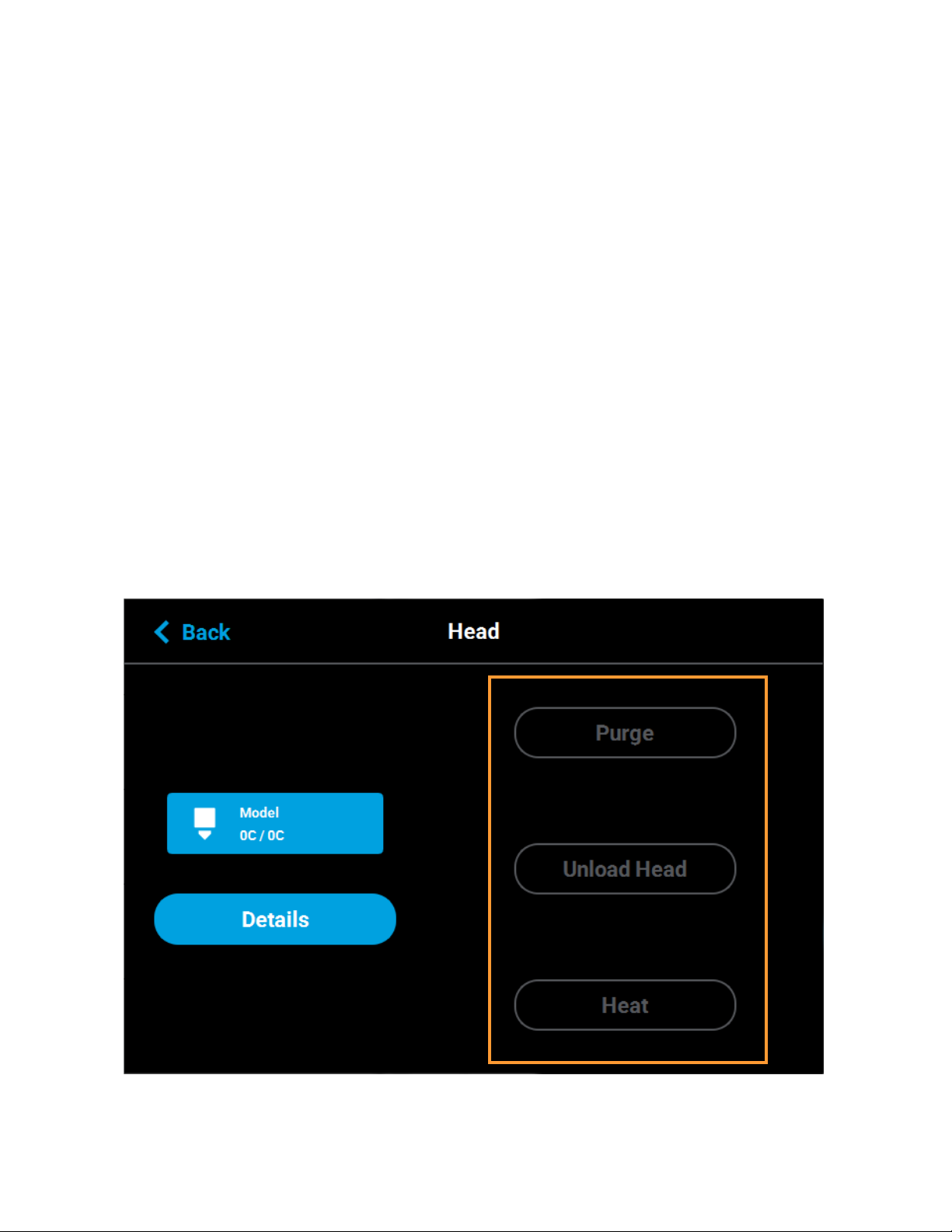
PURGE
Pressing the Purge button instructs the printer to perform a long purge. After pressing this button, the head will
move to the purge position and will heat to a predetermined set point temperature. Once the head reaches this
set point, material will be purged from the tip for about 10 seconds. When changing to or from colored material it
is beneficial to perform multiple purges as this will remove all material remaining within the liquefier tips and/or
tubes to ensure that color mixing doesn’t occur. The Purge button is selectable (i.e. a Purge can be initiated)
when the button is solid blue, and disabled (i.e. a Purge is in process or cannot be initiated) when gray. A
notification badge will be displayed within the button if any preconditions exist preventing the purge from
occurring.
LOAD HEAD/UNLOAD HEAD
Depending on the load status of the selected head, either the Load Head or Unload Head button will be
displayed. Pressing the Load Head button instructs the printer to load material to the corresponding head; the
button will toggle to display the Unload Head button. Pressing the Unload Head button instructs the printer to
unload material from the corresponding head; the button will toggle to display the Load Head button. A
notification badge will be displayed within the button if any preconditions exist preventing the load/unload from
occurring (see “Load/Unload Errors” on page 8-210).
HEAT/COOL
Depending on the state of the printer, either the Heat or Cool button will be displayed. Pressing the Heat button
instructs the printer to heat the corresponding tip to 270°C for no longer than 2 minutes; the button will toggle to
display the Cool button. Pressing the Cool button will instruct the printer to begin cooling the corresponding tip
back to the 0 set point; the button will toggle to display the Heat button. The tip will also begin to cool
automatically if the heat option exceeds the 2 minute time allotment and the Cool button is not pressed.
Figure 4-28: Head Maintenance Page - Menu View
65
Page 75

MATERIAL STATUS ICONS
The Material Status Icons within the Materials page represent the model and support material spools installed/
inserted in the printer. Either two or four icons will be displayed depending on your printer’s configuration. Each
icon displays a number corresponding to the material bay (1-4 for F270 and F370 models and 1-2 for F170
models), colored bars indicating the color of the material currently installed in that bay, the name of the material
currently installed in that bay, and a percentage indicating the current volume of material on that material spool.
Touching one of these icons on the screen, unless otherwise indicated in Table 4-7, will open that material’s
Material Details page. Various graphics will be displayed within the center of the Material Status Icons,
depending on the state of the material bay. The Material Status Icons can appear in the following states (color
usage, highlighting, and descriptions apply to all icons):
Table 4-7: Material Status Icons - Icon States
Icon State Description
Indicates that a material spool is not loaded in the corresponding
material bay, the material bay is empty.
User action required to insert spool. See “Loading Material” on
page 108 and “Material Spool Installation” on page 109 for instructions.
Touching the icon in this state will not display the material’s Material
Details page.
Empty Bay (gray dashed border)
Unusable (semi-solid red)
Indicates that an error occurred when checking the data on the material
spool’s memory chip. The material spool is unusable.
User action required to remove the material spool and replace it with a
valid spool. See “Removing Material Spools” on page 114 and “Material
Spool Installation” on page 109 for instructions.
Touching the icon in this state will not display the material’s Material
Details page.
66
Page 76
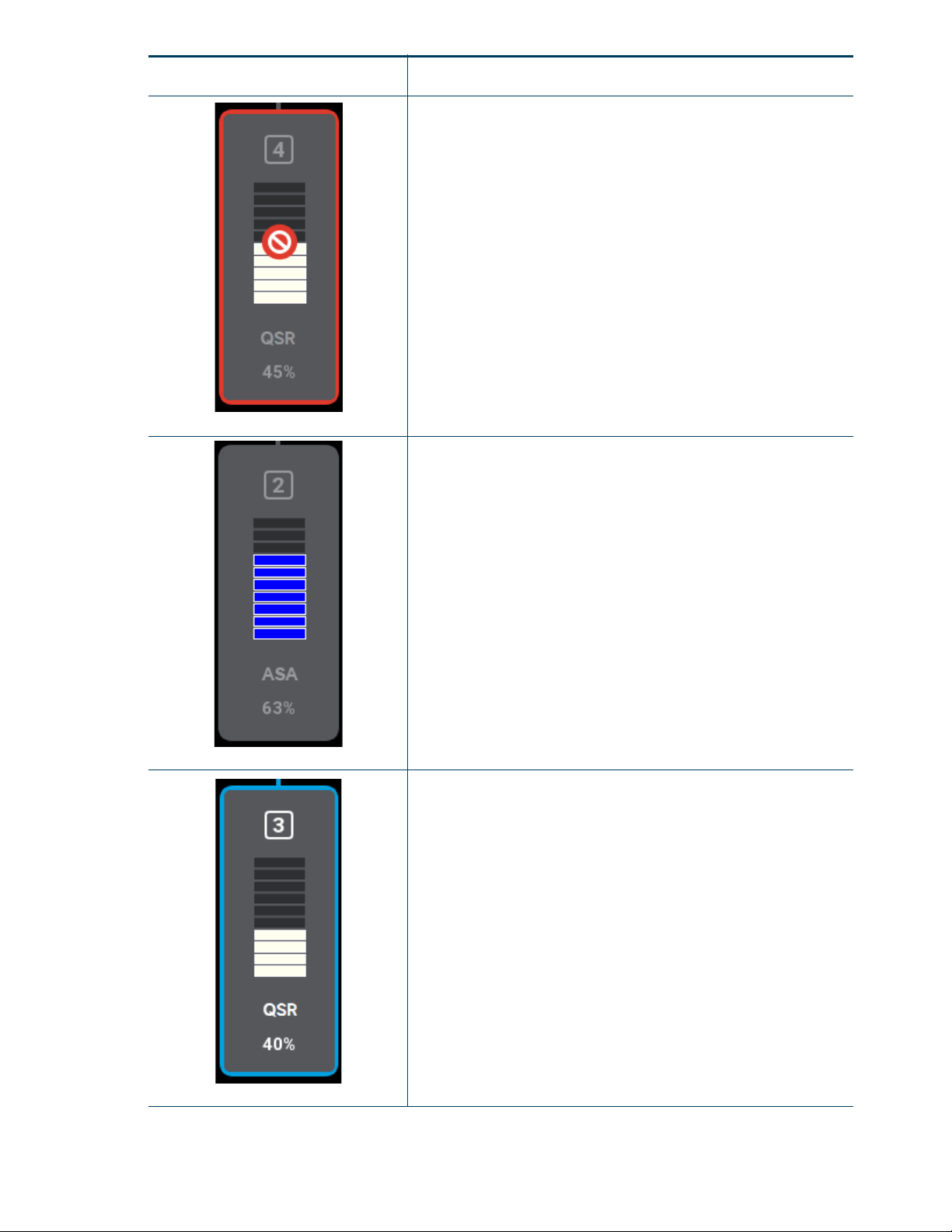
Icon State Description
Indicates that the material spool is invalid. Invalid materials are
materials not licensed or not compatible with the associated head type.
Material from the invalid spool cannot be loaded. User action required
to remove the invalid material spool and replace it with a valid spool
See “Removing Material Spools” on page 114 and “Material Spool
Installation” on page 109 for instructions.
Invalid (red border)
Valid material spool loaded into bay. Material name, color, and current
volume displayed.
Filament from material spool has been advanced and is in contact with
the filament present switch but material from spool is not loaded to the
head. See “Loading Material” on page 108 for instructions.
Unloaded (gray border)
Loaded (blue border)
Valid material spool loaded into by. Material name, color, and current
volume displayed.
Material from spool is loaded to the head and spool is selected to be
used for building.
See “Selecting a Job to Build” on page 122 for instructions on starting a
build. See “Unloading Material” on page 113 for instructions on
unloading material.
67
Page 77

Icon State Description
Material spool is empty - a volume of 0% is displayed.
User action required to remove empty spool. See “Unloading Material”
on page 113 and “Removing an empty Material Spool” on page 114 for
instructions.
Empty Spool (solid yellow)
Indicates that communication with the material bay is not possible.
Please note that this state differs from the unusable state as the icon is
solid red in this state and the bars within the center of the icon are not
visible.
Error (solid red)
Contact Customer Support or your regional Stratasys office if you
experience this icon state (see “Getting Help” on page 204
information).
for contact
68
Page 78

VIEWING MATERIAL DETAILS
Warning/
error
information
displayed
here
To view additional details regarding a particular material, select the desired material by touching its Material
Status Icon on the screen. Doing so will open its Material Details page. If the material bay/spool is in a warning
or error state additional information pertaining to the warning/error will be displayed within the page (see “Load/
Unload Errors” on page 210 for details).
The right portion of the screen displays detailed information about the material spool including:
• State: load state of the material bay.
• Type: the type of material on the material spool. If applicable, material color is also indicated
(material color is also indicated within the center of the Material Status Icon within the left portion of
the screen).
• Current Volume: current volume of material on the material spool, in cubic inches (also indicated via
the percentage displayed within the Material Status Icon within the left portion of the screen).
• Total volume: total volume of material available, in cubic inches, when the material spool was initially
installed into the printer.
The buttons directly below this information allow you to load or unload a material spool as needed or cancel a
load/unload in process (see “Material Load Controls” on page 70 for details). Please note that the functionality
and visibility of these buttons will depend on the load status of the material spool.
The left portion of the screen displays the same Materials Status Icon as is displayed on the Materials page (see
Figure 4-25 on page 60). The number displayed within the top of the icon indicates which material bay the
material spool is installed/inserted into. The colored bars (displayed within the center of the icon) and
percentage (displayed at the bottom the icon) indicate the current volume and color of the material on the spool.
As material is used to build a part, the number of colored bars and the percentage will decrease to indicate the
amount of material consumed. The name of the type of material on the spool is displayed at the bottom of the
icon.
To close this page and return to the main Materials page, press the Back button within the header of the page.
Figure 4-29: View Material Details
69
Page 79
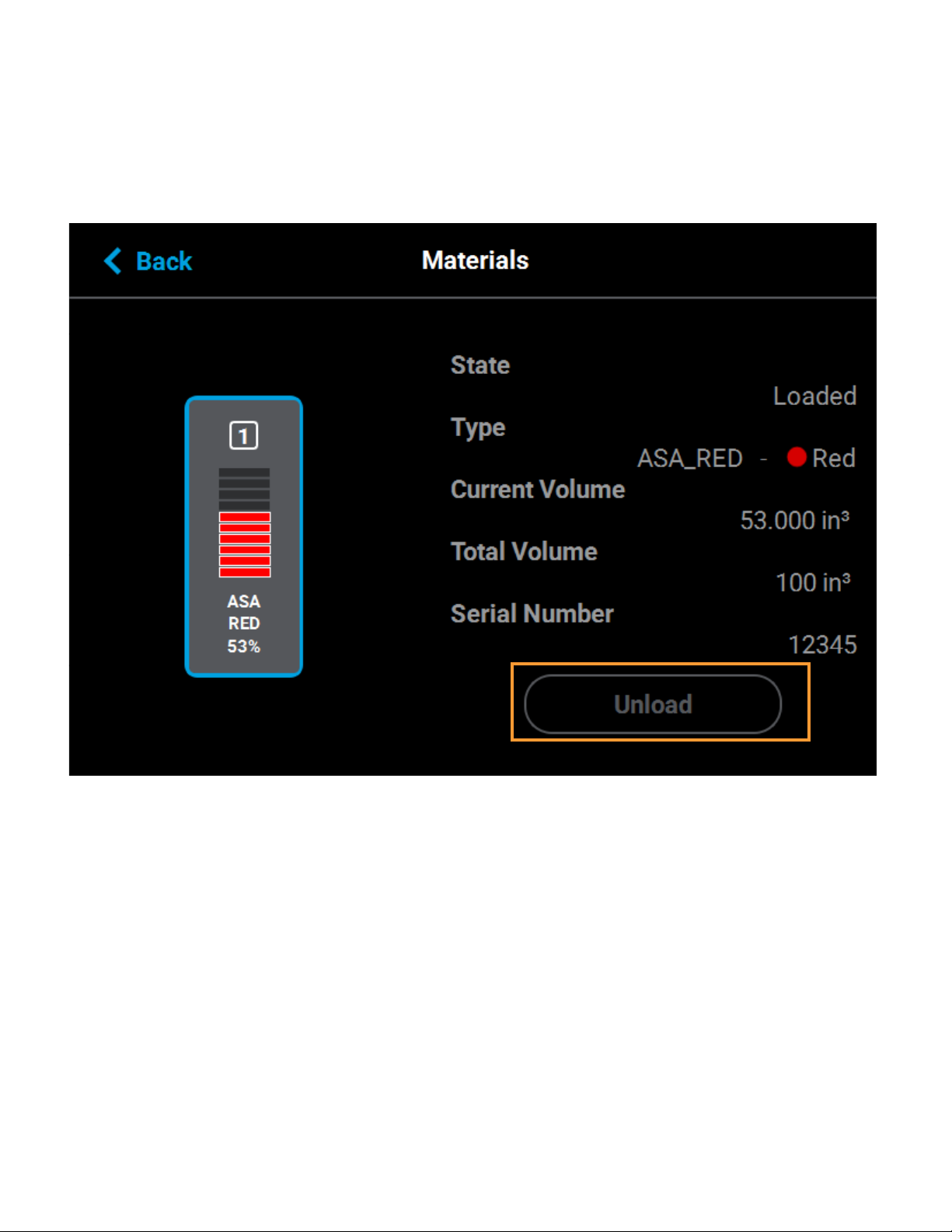
MATERIAL LOAD CONTROLS
The Material Load Control buttons are used to load and unload material to the liquefier within the head, as well
as cancel a material load or unload in process. The Material Load Control buttons are displayed in the lowerright portion of the Material Details page; however, the visibility of these buttons is dependent upon the spool’s
load status. Button states are explained within the tables below.
Figure 4-30: Material Load Control Buttons
The Unload button will be displayed for all material spools whose filament is loaded to the corresponding head.
Pressing this button will instruct the printer to begin the process of unloading material (see “Unloading Material”
on page 113 for details).
The Load button will be displayed for all material spools whose filament has contacted the filament present
switch in the material drive but is not yet loaded to the head, given that material from another spool is not
already loaded to the corresponding head. Pressing this button will instruct the printer to begin the process of
loading material (see “Loading Material” on page 108 for details). If the corresponding head is already loaded
with material, the Load button will appear in its disabled state.
The Cancel button will be displayed for a spool only after the spool’s corresponding Unload or Load button has
been pressed. Pressing this button will instruct the printer to cancel the material load or unload already in
process (see “Material Load/Unload Cancellation” on page 75 for details).
70
Page 80

Table 4-8: Material Load Control Buttons - Load Button States
Button State Description
The Load button is only selectable once a material spool’s
filament has contacted the filament present switch in the
material drive but is not yet loaded to the head, given that
another spool’s material is not already loaded to the head.
Pressing the Load button in this state will instruct the printer
to load material to the corresponding head.
Load button is disabled and not selectable.
Table 4-9: Material Load Control Buttons - Unload Button States
Button State Description
The Unload button is only selectable once a material spool’s
filament is loaded to the corresponding head.
Pressing the Unload button in this state will instruct the
printer to unload material from the corresponding head.
Unload button is disabled and not selectable.
Table 4-10: Material Load Control Buttons - Cancel Button States
Button State Description
The Cancel button is only selectable after the Load or
Unload button have been pressed.
Pressing the Cancel button will cancel the material load/
unload in process.
71
Page 81

FILAMENT PATHWAY STATES
The pathway between the Material Status Icon and corresponding Head Status Icon will take on a variety of
colors and display various graphics, depending on the load state of the associated material spool’s filament. For
printers with two model bays and two support bays (F270 and F370 models), only one material can be loaded to
or unloaded from the corresponding head at a time. The pathway corresponding to the material bay whose
material spool is not being loaded/unloaded will be solid gray or dashed gray, depending on the material’s load
status. Regardless of the number of model and support bays, only one material type can be loaded/unloaded at
a time (i.e. a model and support spool cannot be loaded/unloaded simultaneously). Filament pathways can
appear in the following states (color usage, highlighting, and descriptions apply to both model and support):
Table 4-11: Filament Pathway States
Icon State Description
Indicates that a material spool is not loaded in the corresponding
material bay, the material bay is empty.
After installing a material spool into the corresponding material bay, the
filament pathway will refresh and indicate that filament needs to be
inserted into the drive mechanism.
Empty
Indicates that a valid material spool has been inserted into the
corresponding material bay, but the spool’s filament has not been
detected by the filament present switch.
Insert Filament
Unloaded
Loading
After advancing filament far enough into the drive mechanism for it to
contact the filament present switch, the filament pathway will refresh
and display in its unloaded state.
Indicates that filament from the corresponding material spool has been
advanced and is in contact with the filament present switch, but
material from the spool is not loaded to the head.
Indicates that filament from the corresponding material spool is in the
process of being loaded to the head.
The pathway between the Material Status Icon and the Head Status
Icon will fill, in blue, in the direction that the material spool’s filament is
traveling (towards the head).
Once the load process is complete, the filament pathway will refresh
and display in its loaded state.
Indicates that filament from the corresponding material spool is loaded
to the head and is selected to be used for building.
Loaded
72
Page 82

Icon State Description
Indicates that filament from the corresponding material spool is in the
process of being unloaded from the head. A yellow notification badge
will also be displayed within the center of the corresponding Material
Status Icon.
The pathway between the Material Status Icon and the Head Status
Icon will fill, in yellow, in the direction that the material spool’s filament is
traveling (away from the head).
Once fully unloaded, the filament pathway will remain in this state until
the corresponding material spool is removed from the material bay.
Once the spool is removed, the filament pathway will refresh and
display in its empty state.
Unloading
Red coloring and an associated notification badge indicates a load
related error.
Opening the corresponding Material Details page will provide additional
information on the error state.
Error
73
Page 83

As materials are loaded and unloaded, the pathway between the Material Status Icon and the Head Status Icon
will become colored, and will fill in the direction that the material spool’s filament is traveling (towards the head
or away from the head). Figure 4-31 depicts the functionality displayed when a spool’s filament is being loaded
to the head, while Figure 4-32 depicts the functionality displayed when a spool’s filament is being unloaded from
the head. Opening the Material Details page for the material being loaded/unloaded will provide additional
control over the load/unload. The Cancel button will be displayed within this page, giving you the option to
cancel the material load/unload if necessary.
Material load progress will display the same functionality regardless of whether a model or support spool is
being loaded. Once a spool’s material is loaded to the head, the pathway between the Material Status Icon and
the corresponding Head Status Icon will be solid blue, the Head Status Icon will turn solid blue, and the Material
Status Icon will display a blue border. This indicates that the material spool is selected and in position to be used
to build parts on the printer. The Unload button will be displayed within the Material Details page, indicating that
the spool can be unloaded, if needed. For printers with two model bays and two support bays (F270 and F370
models) only one pathway for a material type can be highlighted at a time as only one material type can be
loaded to the head at a time (i.e. only the Model 1 or 2 pathway can be highlighted at a time, not both).
Figure 4-31: Material Load Progress - Loading
Material unload progress will display the same functionality regardless of whether a model or support spool is
being unloaded. As material is being unloaded from the head, the pathway between the Head Status Icon and
Material Status Icon will be highlighted in yellow and the Head Status Icon will turn solid gray indicating that
material is no longer loaded to the head. A yellow notification badge will be displayed within the center of the
Material Status Icon to indicate that user action is required to complete the unload process.
Opening the Material Details page for the material being unloaded will provide additional details regarding the
unload process. The Load button will be displayed within the Material Details page once the spool’s filament has
been completely retracted indicating that the spool can be reloaded, if needed.
Once material is fully unloaded, filament pathway and Material Status Icon coloring will remain in their unloading
states until the corresponding material spool is removed from the material bay. Once the spool is removed, the
filament pathway and Material Status Icon will refresh and display in their empty states.
74
Page 84

Figure 4-32: Material Load Progress - Unloading
Warning/
error
information
will be
displayed
here
MATERIAL LOAD/UNLOAD CANCELLATION
The Cancel button will only be displayed within the Material Details page for a material that is in the process of
being loaded/unloaded. This button allows you to cancel a material load or unload already in process.
Depending on your printer’s configuration, a warning may be generated after selecting the Cancel button. In the
event of a warning, text will be displayed on the screen to indicate the cause of the warning.
Figure 4-33: Cancel Button
75
Page 85

WORKING WITH THE TOOLS PAGE
The options within the Tools page are organized into 6 categories: Settings, Calibration, Maintenance, Network,
Power, and Light. The Display Area of the Tools page contains a button corresponding to each of these
categories. With the exception of the Light button, pressing the button corresponding to each of these
categories will open an individual page containing printer information that can be viewed as well as printer
settings and preferences which can be configured for that particular category. After selecting any of the buttons
within the Tools page a “Back” button will be displayed within the heading of the page; press this button to return
to the main Tools page.
Within this page you can turn a variety of printer settings on/off (including part placement, standby mode, etc.),
select your printer’s address type (dynamic, static, or Wi-Fi), adjust the brightness of the touchscreen display
and turn the printer or the oven light on/off. As a part of its initial installation and setup (performed by your
authorized service representative) your printer’s network settings will be configured within this page (as
described within “Configuring the Network” on page 14). Once those settings are configured you may need to
occasionally access this page in order to adjust printer preferences.
To access the Tools page, press the Too ls button within the Navigation Menu; a screen similar to the one in
Figure 4-34 will be displayed.
Figure 4-34: Tools Page
76
Page 86

TOOLS PAGE MENU
The Display Area of the Tools page contains 6 buttons. With the exception of the Light button, pressing each of
these buttons will open an individual page containing printer information that can be viewed as well as printer
settings and preferences which can be configured.
Table 4-12: Filament Pathway States
Icon State Description
Pressing the Settings button opens the Settings page. From this page
you can configure and adjust several of the printer’s default settings.
See “Settings” on page 79 for details.
Settings
Pressing the Calibration button opens the Calibration page. From this
page you can preform various printer calibration procedures. See
“Calibration” on page 89 for details.
Calibration
Maintenance
Network
Power
Pressing the Maintenance button opens the Maintenance page. From
this page you can perform various printer maintenance procedures.
See “Maintenance” on page 91 for details.
Pressing the Network button opens the Network page. From this page
you can configure the printer’s network connection. See “Network” on
page 95 for details.
Pressing the Power button opens the Power page. From this page you
can shutdown or restart the printer. See “Power” on page 101 for
details.
The Light button is the only option within the Tools page that does not
open a new page after being pressed. Instead, the Light button allows
you to turn the oven light ON and OFF. An indicator within the upper-left
corner of the button displays the current state of the oven light (ON or
OFF). See “Light” on page 104 for details.
Light
77
Page 87

NAVIGATION OVERVIEW
Right arrow
graphic
Scrollbar
Back button
Page heading
Row
After selecting one of the buttons within the Tools page the touchscreen will refresh to display the details of the
page selected (i.e. selecting the Settings button will open the Settings page). Depending on the options
available for configuration within the selected page, the Display Area of the page may contain more options than
can be displayed at one time. In this case, a scrollbar is displayed along the right-hand side of the page. To
scroll up or down within a page simply touch the scrollbar displayed on the screen and pull the scrollbar in the
direction you’d like to scroll.
A heading is displayed at the top of each page, indicating the name of the page. Each page contains a variety of
settings and preferences that can be configured. Items are organized into individual rows within the Display
Area of the page. The name of the setting/preference to be configured is displayed in bold within the left side of
the row. For some items, current configuration information is displayed directly below the setting/preference
name within the row (for reference purposes).
The graphic displayed within the right side of a row will vary depending on the configuration options available for
that row. Rows containing a right arrow graphic will open a new page allowing you to configure that row’s
settings/preferences. Rows which do not contain a right arrow graphic do not have any configurable options.
After making the necessary adjustments to a row’s settings/preferences, press the Back button in the upper-left
corner of the page to exit the page.
Figure 4-35: Settings Page Content List
78
Page 88

SETTINGS
The Settings page allows you to turn a variety of printer settings on/off (including part placement, standby mode,
etc.), configure the language and units the printer/UI is configured for, and adjust the brightness of the
touchscreen display.
To access the Settings page, press the Settings button within the Tools page; a screen similar to the following
will be displayed. Use the scrollbar (along the right side of the page) to scroll up or down through the list of
available options.
Figure 4-36: Settings Page
WAIT FOR PART
After sending a job file to the printer you would typically need to navigate within the User Interface in order to
select the job from the Queue and start the build. The wait for part setting will instead allow you to send a job file
to the printer which will then immediately start building once received by the printer.
Figure 4-37: Wait for Part
79
Page 89

Pressing anywhere within the row will open the Wait For Part page. Opening this page will automatically put the
printer into a state where it will wait to receive a job file to build immediately. After putting the printer into this
state, you must send the processed job file to the printer via GrabCAD Print. Once the job file is received by the
printer, the job will automatically start building. As such, ensure that the printer has been properly prepared for
the start of a build (see “Before a Build” on page 120 and “Preparing the Printer” on page 120 for details).
Figure 4-38: Waiting for Part
KEEP PREVIOUS JOB
For privacy reasons, you have the option of choosing whether or not the printer’s previous job is stored within
the Job Queue. If you're concerned about other users of your printer seeing what you’ve built, this setting allows
you to prevent other users from accessing the printer’s previous job. When this setting is set to On, the printer
will store its previous job file making it available for re-selection within the Job Queue. When this setting is set to
Off, the printer’s previous job file will be deleted from the Job Queue upon completion of the build. The job’s file
will need to be resent to the printer in order to be built again.
Figure 4-39: Keep Previous Job
80
Page 90
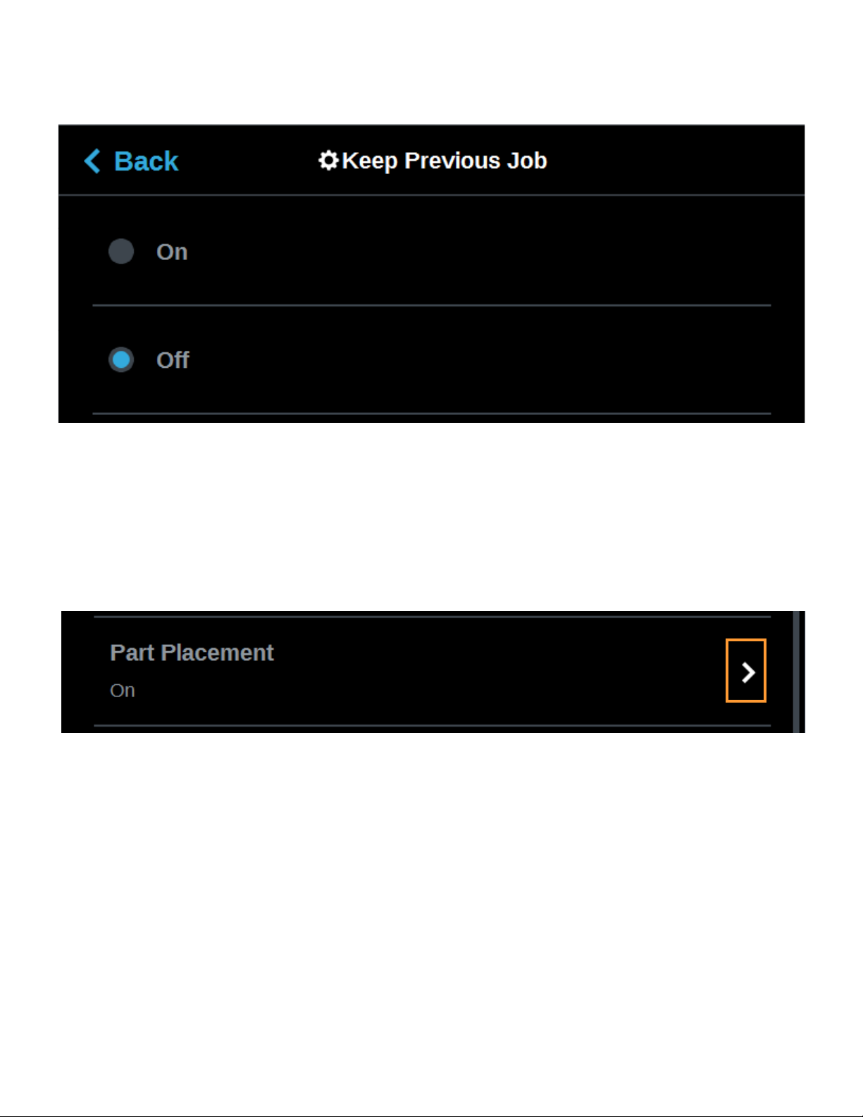
To configure this setting, press anywhere within the row; the Keep Previous Job page will be displayed. Use the
radio buttons within the page to turn the setting On and Off as needed; On is selected by default.
Figure 4-40: Configure Keep Previous Job
PART PLACEMENT
The Part Placement setting gives you the ability to select a job’s placement on a substrate. By default, single
part jobs are built in the center of a substrate while packs are built according to their selected placement within
GrabCAD Print. Therefore, when this setting is set to Off, single part jobs will automatically be built in the center
of the substrate and packs will be built according their selected placement within GrabCAD Print. To configure
this setting, press anywhere within the row; the Part Placement page will be displayed. Use the radio buttons
within the page to turn the setting On and Off as needed.
Figure 4-41: Part Placement
When this setting is set to On, you will be able to select a job’s location on the substrate prior to starting the build
(see “Selecting a Job to Build” on page 122). At the start of a build a dialog will be displayed asking you to select
the part’s build location (see Figure 4-42). The dialog will contain a graphic representing your printer’s platen as
well as a blue bounding box graphic (the imaginary box surrounding the part).
You can select the part’s build location by dragging and dropping the bounding box on the touchscreen; the
bounding box cannot be placed outside the limits of the platen. Pressing the Print button will confirm your
selected placement and start a build. "Ghost box" graphics are also displayed; a "ghost box" represents the
location where a part was built previously. Clicking the Clear History button will clear the display, removing all
"ghost box" items.
81
Page 91

Figure 4-42: Part Placement Dialog
FIRST LAYER MATERIAL
The First Layer Material row displays the material type to be used for the first build layer, Model or Default.
Figure 4-43: First Layer Material
82
Page 92

To configure this setting, press anywhere within the row; the First Layer Material page will be displayed. Use the
radio buttons within this page to select between Model and the Default material, which could be either model or
support material.
Figure 4-44: Configure First Layer Material
UNITS
The Units row displays the type of units the printer is configured for, English (inches) or Metric.
Figure 4-45: Units
To configure this setting, press anywhere within the row; the Units page will be displayed. Use the radio buttons
within this page to select between English and Metric units; English is selected by default.
Figure 4-46: Configure Units
83
Page 93

STANDBY MODE
The Standby Mode setting gives you the ability to put the printer into an energy saving state after the completion
of a build. When the Energy Saver radio button is selected (i.e. Standby Mode is turned On) the printer’s oven
will automatically shut off 2 hours after the completion of a build, thus saving energy. When the Quick Start radio
button is selected (i.e. Standby Mode is turned Off) the printer’s oven will remain On for 60 hours after the
completion of a build and oven temperature will stay at the material’s build temperature.
Figure 4-47: Standby Mode
To configure this setting, press anywhere within the row; the Standby Mode page will be displayed. Use the
radio buttons within the page to select between the Energy Saver and Quick Start options as needed. The Quick
Start radio button is selected by default (i.e. Standby Mode is set to Off by default).
Figure 4-48: Configure Standby Mode
LANGUAGE
The Language row displays the language that the User Interface is configured for. Language options include
English (default), Spanish, French, German, Italian, Russian, Chinese (traditional or simplified), and Japanese.
Figure 4-49: Language
To configure this setting, press anywhere within the row; the Language page will be displayed. Use the scrollbar
(along the right side of the page) to view the list of available languages. Select the radio button corresponding to
your desired language.
84
Page 94

Additionally, the first time the printer is powered ON, a dialog will be displayed asking you to select your desired
language. Once you’ve set your desired language following initial power up, this selection will be retained and
can only be changed by navigating to the Language page and adjusting your language selection.
Figure 4-50: Configure Language
85
Page 95

SCREEN BRIGHTNESS
The Screen Brightness setting allows you to adjust the brightness of the touchscreen display.This setting is
displayed as a percentage with 100% percent representing the greatest amount of brightness available.
Figure 4-51: Screen Brightness
To configure this setting, press anywhere within the row; the Screen Brightness page will be displayed. Within
this page use the slider graphic to adjust brightness as needed. Sliding to the right will increase brightness while
sliding to the left will dim brightness. Please note that you cannot set screen brightness to 0% (completely dim).
Figure 4-52: Configure Screen Brightness
UPnP
UPnP allows the printer to broadcast its Unique Device Name (UDN) address across the network. When this
setting is set to On, the printer will broadcast its UDN across the network allowing GrabCAD Print to
automatically detect the IP address of the printer for communication. When this setting is set to Off, the printer
will not broadcast its IP address across the network and GrabCAD Print will need to be manually configured to
communicate with the printer.
Figure 4-53: UPnP
86
Page 96
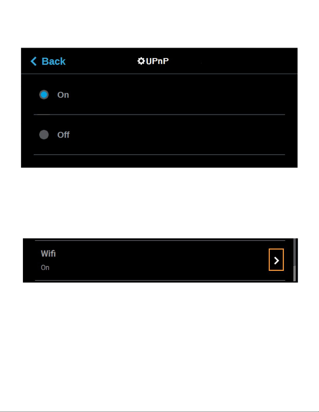
To configure this setting, press anywhere within the row; the UPnP page will be displayed. Use the radio buttons
within the page to turn the setting On and Off as needed; On is selected by default.
Figure 4-54: Configure UPnP
WIFI
The Wifi setting gives you control over the printer’s Wi-Fi capabilities. Please note that the functionality of this
setting is dependent upon the use of a Wi-Fi dongle purchased for use with the printer. When this setting is set
to On, you will be able to configure the printer to scan for and connect to an available Wi-Fi network. You will
then be able to send part files to the printer via this network. When set to Off, Wi-Fi capabilities will be disabled
and you will instead need to send part files to the printer via your facility’s Ethernet connection or through the
use of a USB flash drive (see “Configuring the Network” on page 14 for details).
Figure 4-55: Wifi
87
Page 97

To configure this setting, press anywhere within the row; the Wifi page will be displayed. Use the radio buttons
within the page to turn the setting On and Off as needed; On is selected by default.
Figure 4-56: Configure Wifi
CAMERA
The Camera setting gives you control over the printer’s camera. When this setting is set to On, the printer’s
camera will automatically provide remote monitoring capabilities while a part is being built. When this setting is
set to Off, the camera will be turned off and remote monitoring capabilities will be disabled.
Figure 4-57: Camera
To configure this setting, press anywhere within the row; the Camera page will be displayed. Use the radio
buttons within the page to turn the setting On and Off as needed; On is selected by default.
Figure 4-58: Configure Camera
88
Page 98

CALIBRATION
Note: This section provides an overview of the Calibration page and its features,
but does not go into detail regarding calibration procedures. See “6 Calibration
and Adjustments” on page 140 for detailed calibration procedure information
and instructions.
The Calibration page allows you to perform a variety of calibration procedures on the printer, including:
• Tip Calibration
• Touchscreen Calibration
To access the Calibration page, press the Calibration button within the Tools page; a screen similar to the
following will be displayed.
Figure 4-59: Calibration Page
TIP CALIBRATION
The printer’s calibration status will be displayed within the Tip Calibration row. Calibrated or Not Calibrated will
be displayed depending on the printer’s Calibration status.
Pressing anywhere within the Tip Calibration row will open a page allowing you to select from a variety of tip
calibration options.
Figure 4-60: Tip Calibration
89
Page 99

The Tip Calibration page contains an option for performing an Automatic Tip Calibration as well as a Manual Tip
Calibration. Pressing the Start button associated with either of these options will allow you to perform that
particular calibration procedure. Each calibration procedure is delivered in the form of a wizard which will guide
you through the process of performing the calibration procedure. See “Automatic Tip Calibration” on page 142
and “Manual Tip Calibration” on page 144 for detailed instructions.
Figure 4-61: Tip Calibration Options
TOUCHSCREEN CALIBRATION
Pressing anywhere within the Touchscreen Calibration row will open a dialog allowing you to recalibrate the
touchscreen display. See “Touchscreen Calibration” on page 154 for detailed instructions.
Figure 4-62: Touchscreen Calibration
90
Page 100

MAINTENANCE
Note: This section provides an overview of the Maintenance page and its
features, but does not go into detail regarding printer maintenance procedures.
See “7 Maintenance” on page 158 for detailed maintenance information.
From this page you can perform a variety of maintenance procedures on the printer, and view diagnostic/printer
state information. Please note that advanced maintenance must be performed by an authorized service
representative only.
To access the Maintenance page, press the Maintenance button within the Tools page; a screen similar to the
following will be displayed.
Figure 4-63: Maintenance Page
91
 Loading...