


User Guide

2
Legal Notice
The information in this document is subject to
change without notice.
STRATASYS, INC. MAKES NO WARRANTY
OF ANY KIND WITH REGARD TO THIS
MATERIAL, INCLUDING, BUT NOT LIMITED
TO, THE IMPLIED WARRANTIES OF
MERCHANTABILITY AND FITNESS FOR A
PARTICULAR PURPOSE. Stratasys, Inc. shall
not be liable for errors contained herein or for
incidental or consequential damages in
connection with the furnishing, performance, or
use of this Material.
This document is protected by copyright. All
rights reserved. Its use, disclosure, and
possession are restricted by an agreement
with Stratasys per software copyright. No part
of this document may be photocopied,
reproduced or translated into another language
without the prior written consent of Stratasys,
Inc. Printed in the USA.
Trademark Credits
© Copyright 2008 Stratasys, Inc. All rights
reserved.
Stratasys, Dimension and CatalystEX are
registered trademarks of Stratasys, Inc.
uPrint is a trademark of Stratasys, Inc.
Windows XP, and Windows Vista are
registered trademarks of Microsoft.
.
Conforms to ANSI/UL std. 60950-1-2003
Certified to CAN/CSA C22.2 no. 60950-1-03
The uPrint by
accordance with the EU Machinery, Low Voltage and Electromagnetic
Dimension system conforms with the following standards,
Compatibility Directives: EU 98/37/EEC, EU 73/23/EEC
amended by 93/68/EEC, EU 89/336/EEC
Stratasys Document Number 206465-0001
in

3
Stratasys, Inc. 7665 Commerce Way Eden Prairie, MN 55344
Phone: 952.937.3000 Fax: 952-937-0070
www.stratasys.com
Declaration of Conformity
Manufacturer Stratasys, Inc.
7665 Commerce Way
Eden Prairie, MN 55344-2080
Type of Equipment 3D Printer
Model Number 180-00108 uPrint 3D Printer
180-00109 uPrint 3D Printer
180-00110 uPrint 3D Printer
We declare under our sole responsibility that the devices mentioned above comply with the
following EU Directives:
Electromagnetic Compatibility 89/336/EEC
(EMC)
Machine 98/37/EC
Low Voltage 73/23/EEC amended by 93/68/EEC
Common Technical Specification EN55022:1998 EN6100-3-2: 2003
Used for demonstration of EN55024:1998 EN6100-3-3: 1995
Compliance EN60950-1:2006
Date of Validity: September 8, 2008
Design and Technical Construction Stratasys, Inc.
File maintained at: 7665 Commerce Way
Eden Prairie, MN 55344-2080
Name of Authorized Signatory: S. Scott Crump
Position Held in Company: Chief Executive Officer
Signature:

4
uPrint™ Limited Warranty
Stratasys, Inc. ("Stratasys") warrants its' uPrint™ 3D Printer system and associated peripheral devices and
replacement parts (collectively, the "Product") purchased from Stratasys or an Authorized Stratasys Reseller to be free
from defects in material and workmanship according to the terms and conditions stated below:
Warranties extend only to the original purchaser of the Product. The warranty on the original Product, as delivered,
extends for one year starting on the date of delivery. Your sole remedy as purchaser under this Limited Warranty shall
be repair or replacement as provided herein.
To preserve your warranty rights, all uPrint™ Products must be installed in accordance with the then-current User
Guide available at www.uPrintDimension.com. During the Limited Warranty period, Stratasys or its' designated
representative will, at their option, repair or replace a defective Product as set forth below. Service Parts and
replacement Products will be furnished on an exchange basis, and will be either new or refurbished. All replaced parts
or replaced Products become the property of Stratasys, and you will be invoiced for replacement parts if defective
parts are not returned as directed by Stratasys under this Limited Warranty.
Stratasys will bear the cost of returned parts, as well as for shipping new or rebuilt replacement parts to you, provided
that you report the warranty claim within the Limited Warranty period and obtain return instructions from Stratasys prior
to return. Replacement parts independently carry a 90-day warranty from date of shipment from Stratasys or
designated representative location. Consumable parts are not covered by this Limited Warranty. Warranty services
may be provided by Stratasys, an Authorized Reseller, or a third party service provider designated by Stratasys.
No coverage or benefits under this Limited Warranty will exist if any of the following conditions apply:
(a)The uPrint™ Product has been subjected to abnormal use, improper or inadequate maintenance, unauthorized
modifications, unauthorized repair, misuse, abuse, exposure to moisture, flooding, fire, electrical problems associated
with incoming power, or other acts which are not the fault of Stratasys, Inc.
(b)Stratasys' Customer Service Department was not notified of the defect or malfunction of the uPrint™ system prior to
expiration of the one year warranty period.
(c)Parts or consumables were installed and used that were not certified or approved by Stratasys.
Stratasys will also not be liable under any circumstances for Product replacement or associated labor, loss of use, loss
of profits, or for any other indirect, incidental, collateral, exemplary, punitive, consequential or special damages, or
losses arising out of the purchase of uPrint™ Products and/or out of this limited warranty, even if Stratasys or its'
designated representative have been advised of the possibility of such damages or claims. To the extent such claims
are not excludable as adjudged by a court of competent jurisdiction, you agree to accept as sole and exclusive remedy,
a payment equal to the original purchase price for the product adjudged to be defective.
SOME COUNTRIES, REGIONS, STATES OR PROVINCES DO NOT ALLOW THE EXCLUSION OR LIMITATION OF
REMEDIES OR OF INCIDENTAL, PUNITIVE, OR CONSEQUENTIAL DAMAGES, OR THE APPLICABLE TIME
PERIODS, SO THE ABOVE LIMITATIONS OR EXCLUSIONS MAY NOT APPLY TO YOU. EXCEPT TO THE EXTENT
LAWFULLY PERMITTED, THIS LIMITED WARRANTY DOES NOT EXCLUDE, RESTRICT OR MODIFY, AND IS IN
ADDITION TO THE STATUTORY RIGHTS APPLICABLE TO THE SALE OF THIS PRODUCT TO YOU.
This warranty gives you specific legal rights and you might also have other rights that vary from country/region to
country/region, state to state, or province to province.
EXCEPT FOR THIS LIMITED WARRANTY, AND TO THE FULLEST EXTENT ALLOWED BY LAW, NEITHER
STRATASYS NOR ANY AUTHORIZED RESELLER MAKES ANY OTHER WARRANTY OF ANY KIND, EXPRESS
OR IMPLIED, INCLUDING ANY IMPLIED WARRANTY OF MERCHANTABILITY OR FITNESS FOR A PARTICULAR
PURPOSE. STRATASYS DOES NOT OFFER, ASSUME OR AUTHORIZE THE OFFER OR ASSUMPTION OF
LIABILITY FOR IT OR FOR ANY OTHER WARRANTY, EITHER EXPRESS OR IMPLIED BY ANY AUTHORIZED
RESELLER OR OTHER INDEPENDENT THIRD PARTY.

Table of Contents 5
Table of Contents
Introduction
How To Use This Guide .................................................................................................................................9
Sections of the User Guide ............................................................................................................................9
Overview... .............................................................................................................................................. 9
Setup... .................................................................................................................................................... 9
Operation... ............................................................................................................................................. 9
Preventive Maintenance... .......................................................................................................................9
Troubleshooting and Maintenance... ....................................................................................................... 9
Support... ................................................................................................................................................. 10
Recycling... .............................................................................................................................................. 10
Overview
Finding More Information ...............................................................................................................................13
Setup
Minimum Requirements: ................................................................................................................................14
Workspace Requirements: ......................................................................................................................14
Facility Requirements & Environmental Specifications: ..........................................................................14
Work Station Requirements: ...................................................................................................................14
Safety ............................................................................................................................................................ 15
Hazard Classifications: ............................................................................................................................15
Unpacking the Startup Kit ..............................................................................................................................16
Unpacking the Material Bay ........................................................................................................................... 17
Unpacking the Printer .................................................................................................................................... 18
Set up the Material Bay and Printer ...............................................................................................................19
Inserting a modeling base ..............................................................................................................................21
Inserting a modeling base: ......................................................................................................................21
Connecting the printer and material bay(s). ...................................................................................................22
Power Cable ..................................................................................................................................................23
Connecting the power cable: ...................................................................................................................23
Network/Crossover Connections ................................................................................................................... 23
Connecting the network cable: ................................................................................................................23
Connecting the crossover cable: ............................................................................................................. 23
Powering ON .................................................................................................................................................24
Powering ON the printer: .........................................................................................................................24
Initial Language Setup ...................................................................................................................................24
Setting your default language: ................................................................................................................24
Software .........................................................................................................................................................25
Installing CatalystEX: ..............................................................................................................................25
Verifying System Software: .....................................................................................................................25
Networking Your Printer .................................................................................................................................25
Establishing communication on a Dynamic network: .............................................................................. 25
Setting the Static Network address: ........................................................................................................26
Connecting Directly To Your PC (if no network is available) .........................................................................27
Connecting directly to the PC with a crossover cable: ............................................................................27
System Software ............................................................................................................................................29
Updating System Software: .....................................................................................................................29
Installing a spool of material into the material carriers ...................................................................................29
Stratasys Document Number 206465-0001

Table of Contents 6
Installing a spool of material into the carrier: ...........................................................................................29
Adding material carriers to the single material bay ........................................................................................31
Adding material carriers to the material bay: ...........................................................................................31
Loading material to the head for the single material bay ...............................................................................31
Adding material carriers to the dual material bays .........................................................................................31
Building a Test Part .......................................................................................................................................32
Operation
Powering On ..................................................................................................................................................33
Display Panel and Keypad .............................................................................................................................33
System Software Overview ............................................................................................................................34
CatalystEX Overview .....................................................................................................................................35
Setting up your STL file for printing ...............................................................................................................36
Opening your STL file with CatalystEX: .................................................................................................. 36
Setting the scale of your STL file: ...........................................................................................................36
Setting the orientation of your STL file: ...................................................................................................36
Selecting the model interior fill for your part: ...........................................................................................37
Selecting the support material fill for your part: ....................................................................................... 37
Adding your STL file to the pack: ............................................................................................................ 37
Printing your STL file: ..............................................................................................................................37
Building a part ................................................................................................................................................38
Starting a build from a remote location: ..................................................................................................38
Starting a build from the display panel: ...................................................................................................38
The display panel during build .......................................................................................................................38
Chamber Lights .............................................................................................................................................39
To set the chamber lights to always on: ..................................................................................................39
Pausing a build ..............................................................................................................................................39
Resuming a build that has been paused ....................................................................................................... 39
Canceling a build ...........................................................................................................................................39
Cancel a build: ........................................................................................................................................39
Removing a completed part ...........................................................................................................................40
Remove a completed part from the printer: .............................................................................................40
Remove a part from the modeling base: ................................................................................................. 40
Removing support material ............................................................................................................................ 41
Emptying the purge bucket ............................................................................................................................ 41
Replacing material for single material bay .....................................................................................................42
Removing material from the printer: ........................................................................................................42
Removing material from the printer: ........................................................................................................42
Dual material bay LED’s ................................................................................................................................43
Replacing material spools ..............................................................................................................................43
Removing a spool of material from the carrier: .......................................................................................43
Installing a spool of material in to the carrier: ..........................................................................................43
Storing material ..............................................................................................................................................43
Auto power down ........................................................................................................................................... 45
Setting up auto power down: ...................................................................................................................45
Cancelling auto power down: ..................................................................................................................45
Powering off ...................................................................................................................................................45
Resuming operations from Standby mode .................................................................................................... 45
Continue operation from Standby mode: .........................................................................................
.......45
Preventive Maintenance
Daily ............................................................................................................................................................... 46
Empty the purge bucket .......................................................................................................................... 46
Inspect the tip wipe assembly ................................................................................................................. 46
Inspect the tip shields ..............................................................................................................................46
Stratasys Document Number 206465-0001

Table of Contents 7
500 Hour maintenance ..................................................................................................................................46
Replace the tip wipe assembly ................................................................................................................46
Replace the tip shields ............................................................................................................................46
2000 Hour maintenance ................................................................................................................................46
Tip replacement ...................................................................................................................................... 46
Troubleshooting and Maintenance
Troubleshooting Checklist .............................................................................................................................47
Fault Determination Codes ............................................................................................................................ 49
Welcome Kit Tools .........................................................................................................................................50
Diagnosing Loss of Extrusion ........................................................................................................................50
Diagnose loss of extrusion: .....................................................................................................................50
Clogged Extrusion Tip ................................................................................................................................... 51
Clearing a clogged extrusion tip: ............................................................................................................. 51
Recovering From Loss of Extrusion ...............................................................................................................53
Cycling Power ................................................................................................................................................55
To cycle power to the printer: ..................................................................................................................55
Tip Wipe Assembly ........................................................................................................................................56
Replacing the tip wipe assembly: ............................................................................................................56
Tip Shield Replacement .................................................................................................................................57
Extrusion Tip Replacement and Calibration .................................................................................................. 59
Removing Tips: .......................................................................................................................................59
Installing Tips: .........................................................................................................................................60
Tip Calibration: ........................................................................................................................................62
Remove Debris Buildup ................................................................................................................................. 63
Vacuum Build Chamber .................................................................................................................................63
Clean Door .....................................................................................................................................................63
Chamber Light Bar .........................................................................................................................................64
Replace chamber light bar: ..................................................................................................................... 64
Support
Registration ....................................................................................................................................................65
Customer Support ..........................................................................................................................................65
Recycling
Removing the EEproms from the material guides .........................................................................................67
Stratasys Document Number 206465-0001

Introduction 8
Introduction
uPrint is designed with ultimate simplicity in mind. The system enables you to build parts quickly, even if
you’ve never used a 3D printer before.
The system models with ABSplus, so modeled parts are strong and durable. ABSplus also ensures you will
be able to drill, tap, sand and paint your creations. With Soluble Support Technology (SST), your
completed parts are quickly available for review and test. uPrint is an innovative combination of proprietary
hardware, software and material technology.
Welcome to the new Dimension of 3D modeling!
Stratasys Document Number 206465-0001

Introduction 9
How To Use This Guide
This User Guide is laid out in easy to follow sections which cover Set-up, Operation, Maintenance, and
Troubleshooting of your uPrint 3D printer. Be sure to read each section carefully so that you will get the
best performance from your system.
Throughout the User Guide, text representing Interface Messages that appear on the Display Panel are
presented in a bold font.
Sections of the User Guide
Overview...
Provides a quick reference for the layout of the printer and its operating components. Overview also
provides a quick reference for sources of additional information.
Setup...
Guides you through the initial printer installation and setup. Topics include:
• Unpacking
• Connecting power
• Installing software
• Connecting to a computer network.
Generally, topics in setup are only accomplished during installation or relocation of the printer.
Operation...
Further develops your understanding of the printer by explaining:
• The User Interface
• Adding and removing material
• Building parts
• Removing completed parts and support material.
The tasks presented are common procedures accomplished during the normal operation of the printer.
Preventive Maintenance...
Lists several tasks to be done on a periodic basis.
Troubleshooting and Maintenance...
In the event your printer has any issues, a troubleshooting checklist, fault determination codes, diagnosing
a Loss of Extrusion, recovering from a Loss of Extrusion, startup and networking issues resolutions are
provided. This section also lists routine procedures that keep your printer functioning at its best.
Stratasys Document Number 206465-0001

Introduction 10
Support...
Guides you through getting technical support and/or service for your uPrint 3D Printer, as well as
consumable products and ordering information.
Recycling...
This section will explain which materials for the uPrint system and packaging are recyclable.
Stratasys Document Number 206465-0001
Overview 11
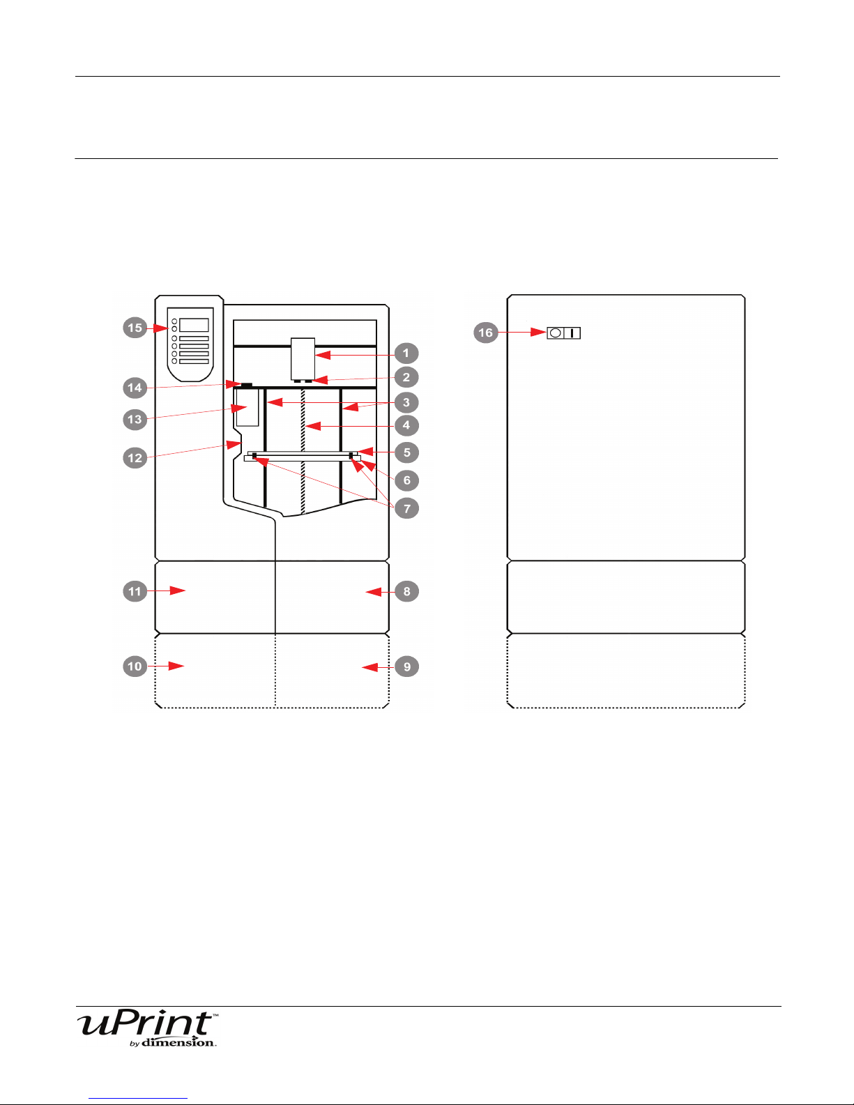
Front View
Left side View
Overview
uPrint builds models from CAD STL files. The system builds three-dimensional parts by extruding a bead
of ABSplus through a computer-controlled extrusion head, producing high quality parts that are ready to
use immediately after completion.
Figure 1: Front and left side view of printer.
1 Extrusion Head 9 Optional Material Bay, Model Side
2 Extrusion Tips 10 Optional Material Bay, Support Side
3 Guide Rods 11 Material Bay, Support Side
4 Lead Screw 12 Door Interlock System
5 Modeling Base 13 Purge Bucket
6 Z Platform 14 Tip Wipe Assembly
7 Modeling Base Retainers (2) 15 Display Panel
8 Material Bay, Model Side 16 Power ON/OFF Switch
Stratasys Document Number 206465-0001

Overview 12
Figure 2: Rear view of printer
1 Optional Material Bay 9 Support Material Tube
2 Optional Model Material Tube 10 UPS Connection
3 Material Bay 11 Material Bay Cable Connector
4 Model Material Tube 12 RJ-45 Network Connector
5 Circuit Breaker 13 Diagnostics Cable Connector
6 AC Power Cord Connector 14 Material Bay Communications Cable
7 Model Material Y Connector 15 Optional Support Material Tube
8 Support Material Y Connector 16 Optional Material Bay Communications Cable
The uPrint system consists of two primary components — the uPrint 3D printer and Material Bay.
CatalystEX is the preprocessing software that runs on Windows XP Pro or Windows Vista platform.
uPrint’s build envelope measures 203 x 152 x 152 mm (8 x 6 x 6 in). Each material carrier contains 492 cc
(30 cu. in.) of usable material — enough to build continuously for about 48 hours without reloading. You
can add an optional material bay that will automatically load more material as a carrier runs out.
Stratasys Document Number 206465-0001

Overview 13
Finding More Information
Other references are available for use with the uPrint system.
CatalystEX Online Help
Simple operating instructions for
CatalystEX are available through
CatalystEX Dynamic Help, which
is included with CatalystEX and
displayed in the Dynamic Help
window. You can also see
CatalystEX Help from the menu
bar - Help>Contents
World Wide Web
Additional information is
available at:
http://www.uPrintDimension.com
Stratasys Document Number 206465-0001

Setup 14
Setup
Minimum Requirements:
Workspace Requirements:
System Specifications
Printer Height 762mm (30 inches)
Printer Width 660mm (26 inches)
Printer Depth 660mm (26 inches)
Printer Weight 62 Kg (137 lbs.)
Material Bay Height 153mm (6 Inches)
Material Bay Width 660mm (26 inches)
Material Bay Depth 660mm (26 inches)
Material Bay Weight 17 Kg (37 lbs.)
Ventilation Requirements 115 mm (4.5 in) minimum space behind unit for air circulation.
153 mm (6 in) minimum space around the printer for air circulation.
Installation Location Stable flat surface capable of holding 100Kg (220 lbs).
Facility Requirements & Environmental Specifications:
Facility Requirements
Dedicated outlet voltage
requirements (Nominal):
Ambient Temperature: 15-30°C (60-86°F) Operating
Relative Humidity: 30-70%, Non-condensing Operating
Network connection: Ethernet 10/100 Base T
Optional UPS for power
interruptions:
BTU/hr 2550 BTU/hr
dBA’s (Decibels) 55dBA MAX Idle and 62dBA MAX Operating
90-132 VAC, 47-63 Hz, 12 Amp minimum (20 Amp recommended)
–or–
195-264 VAC, 47-63 Hz, 7 Amp minimum (10 Amp recommended)
Rated Power – 1440 VA
Output Power – 1500 watts
Work Station Requirements:
You must use a CAD software program that is capable of creating. STL files. For detailed information
See Release Notes... http://www.uPrintDimension.com
Stratasys Document Number 206465-0001
Setup 15
Safety
uPrint is designed to be a safe and reliable 3D printer. However, normal operation will require that you
access areas of the printer that are potentially hazardous.
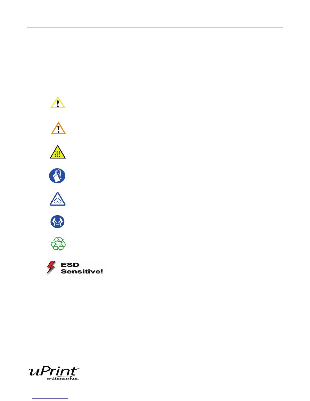
Hazard Classifications:
Please be aware of the following hazard classifications that are used throughout this guide.
CAUTION: Indicates a potentially hazardous situation which, if not avoided,
may result in minor or moderate injury.
WARNING: Indicates a potentially hazardous situation which, if not avoided,
could result in serious injury.
Hot Surface: The hot surface sign indicates the presence of devices with high
temperatures. Always use extra care, and wear safety gloves, when
working around heated components
Gloves: When performing some maintenance procedures, the machine may be
hot and gloves will be required to avoid burns.
Safety Glasses: Wear safety glasses to avoid injury to your eyes.
Lifting Hazard: Lift with two or more people to avoid serious injury.
Recycle: Use proper recycling techniques for materials and packaging.
ESD: Use standard electrostatic discharge (ESD) precautions
when working on or near electrical circuits.
Stratasys Document Number 206465-0001
Setup 16
A
B
C
A
B
C
See Figure 4
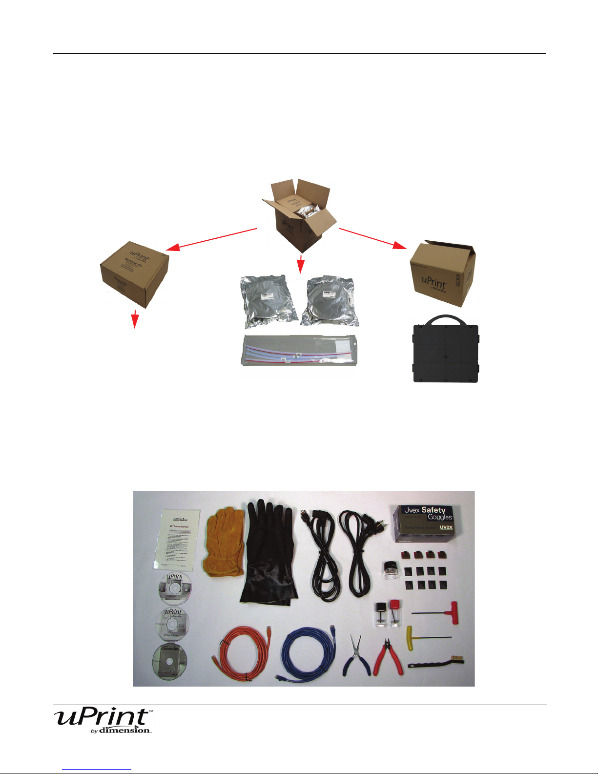
Unpacking the Startup Kit
1. Carefully cut the top of the box, open and remove the contents.
2. Remove the welcome kit box and open.
3. Remove the model and support material spools.
4. Remove the material guide tubes.
5. Remove the box of substrates.
Figure 3: Startup Kit
Figure 4: Welcome Kit Contents
Stratasys Document Number 206465-0001
Setup 17
A
B
C
A
B
C
M
S
Unpacking the Material Bay
1. Carefully cut the top of the box, open and lay it on its side.
2. Remove the material bay cable.
3. Remove the material bay.
4. Remove the model and support carriers.
Figure 5: Material Bay
Stratasys Document Number 206465-0001
Setup 18
1
2
3
4
5
6
A
B
C
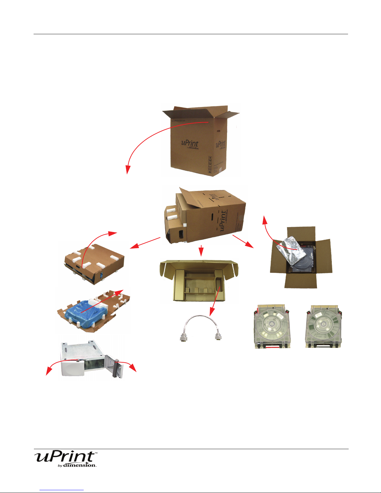
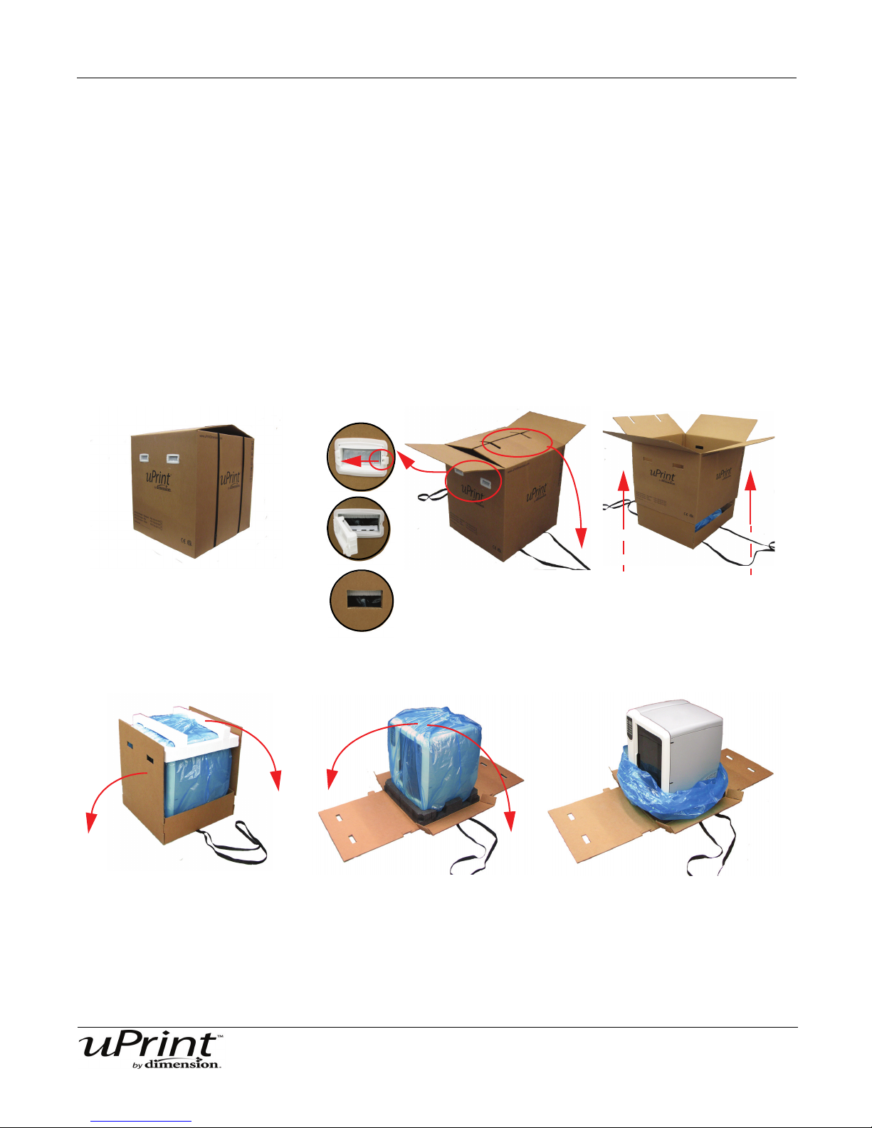
Unpacking the Printer
1. Place the printer close to the area where it will be located.
2. Remove the handles from the box.
3. Carefully cut the top of the box open, do NOT cut the straps that contain the box.
4. Unfold the top of the box and remove the straps.
5. Remove the handles, pulling the tabs outward.
6. Raise the outer box up and off of the inner box.
7. Fold down the sides of the inner box to reveal the printer.
8. Remove the foam from the top of the printer.
9. Cut the top of the blue plastic bag the printer is enclosed in.
10. Lower the plastic bag, the printer should now be visible.
Figure 6: uPrint 3D Printer
Stratasys Document Number 206465-0001

Setup 19
Set up the Material Bay and Printer
Once the Printer and the Material Bay are unpacked, they will need to be aligned and stacked before
operation.
1. Place the Material Bay on a stable, flat surface where you will have your uPrint 3D printer located.
2. The Material Bay has 4 holes for the feet and 2 holes for the alignment pins. See Figure 7. These must
be seated properly for mechanical stability.
3. Align the 4 feet and 2 two pins on the bottom of the printer with the holes on top of the Material Bay and
set in place.
See Figure 7.
LIFTING HAZARD
Use proper moving and lifting techniques when positioning the unit.
Figure 7: System Stacked (Shown with optional Material Bay)
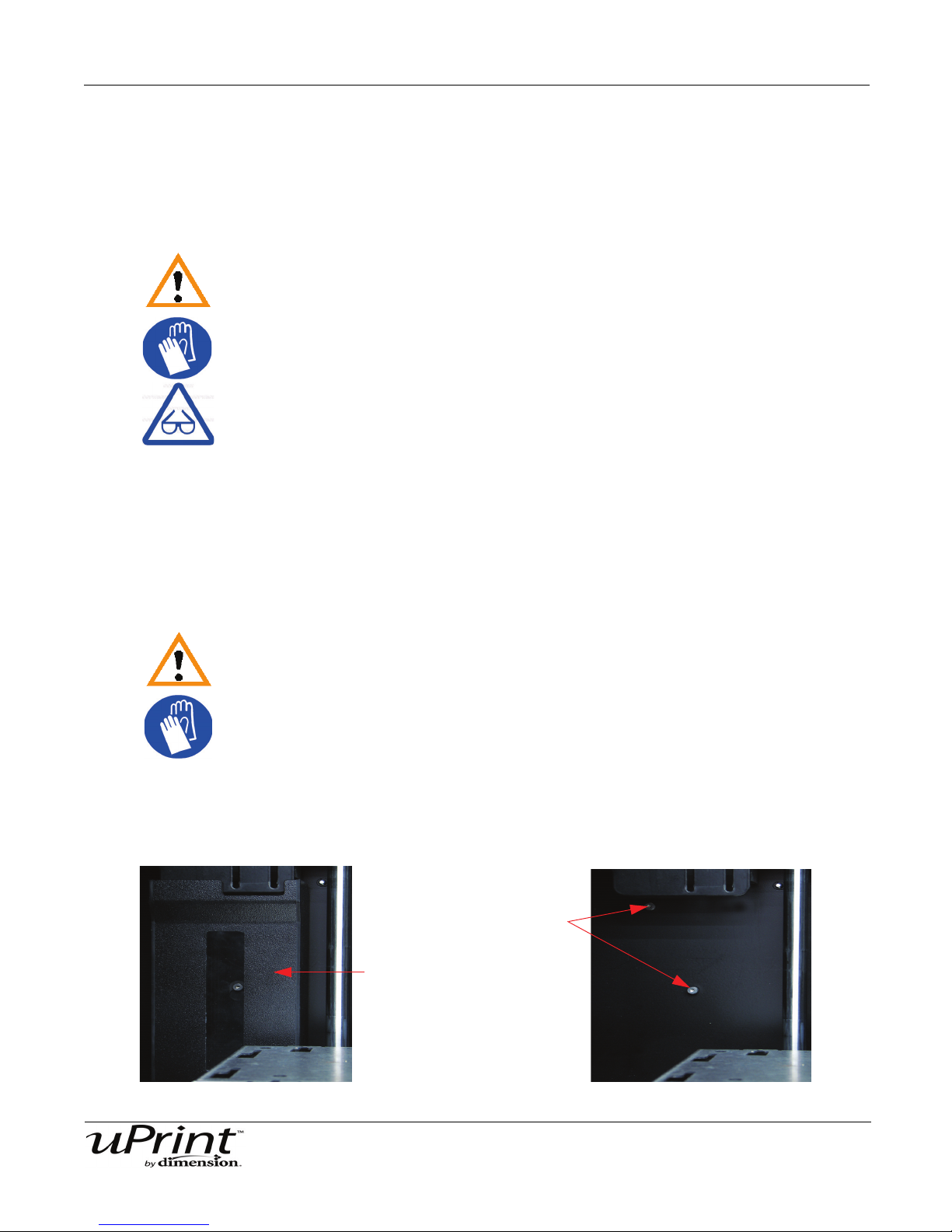
4. Open the printer door and remove the substrate and VCI emitter and discard. See Figure 8.
5. Remove the shipping foam from the Z stage guide rods and recycle. See Figure 8.
6. Remove the belt retaining clips and recycle. See Figure 8.
Stratasys Document Number 206465-0001

Setup 20
Remove belt retaining clips
and recycle.
Remove modeling base with
VCI emitter and discard
Remove shipping foam
from Z stage guide rods
and recycle.
Figure 8: Open the chamber door and remove shipping materials
WARNING
The Lead Screw and Guide Rods are lubricated with a thin coat of Krytox
grease. Krytox grease can cause skin irritation. Be careful not to get the
grease on your hands or clothing.
Stratasys Document Number 206465-0001

Setup 21
Align tabs with slots
Inserting a modeling base
The modeling base is the tray the printer uses to build the models on. You will need to use a new modeling
base for every build.
Inserting a modeling base:
1. Make sure the two retainers are turned down so they do not interfere with modeling base installation.
2. Set the modeling base on the Z platform aligning the tabs on the modeling base with the slots on the
metal tray. See Figure 9.
Figure 9: Z Platform Slots
3. Slide the modeling base down and toward the back of the unit until its front edge (with the handle) is
flush with the front edge of the tray. See Figure 10.
Figure 10: Slide modeling base in place
4. Secure the modeling base with the two retainers by turning them up. See Figure 11.
Figure 11: Turn retainers to lock modeling base in place.
Stratasys Document Number 206465-0001

Setup 22
Remove only if
using the optional
material bay
Firmly push tubes
into fittings
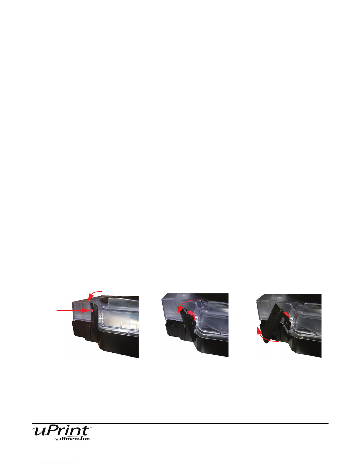
Connecting the printer and material bay(s).
1. Connect the material tubes from the material bay(s) to the printer. The material tube with the red stripe
is for the model material and the material tube with the black stripe is for support material. See Figure
12.
Figure 12: Material Tube connections
2. Connect the material bay communication cable(s) from the material bay(s) to the printer. Do NOT con-
nect the material bay communication cable(s) while the printer is powered on. See Figure 13.
Figure 13: Material Bay Communication Cable
Note:
If you are using the optional second material bay, the longer
material tubes are for the lower material bay and the shorter
material tubes are for the upper material bay.
Stratasys Document Number 206465-0001

Setup 23
Power Cable
Connecting the power cable:
1. Connect the power cable to the back of the printer.
2. Connect the power cable to the dedicated power outlet. See Figure 14.
Note:
Do not use an extension cord or a power strip, using these can
possibly cause intermittent power issues.
Figure 14: Power cable connection
Network/Crossover Connections
Connecting the network cable:
1. Connect the network cable (blue) to the network connection at the back of the printer.
2. Connect the network cable to the dedicated outlet or network hub.
If not using a network and connecting directly to a PC, you will need to use a crossover cable.
Connecting the crossover cable:
1. Connect the crossover cable (orange) to the network connection at the back of the printer.
2. Connect the crossover cable to the computer that will be sending the parts to the printer.
Figure 15: Network connection
Stratasys Document Number 206465-0001

Setup 24
1
2
Powering ON
The circuit breaker is located at the lower left corner on the rear of the printer. The power switch is located
on the left panel towards the rear of the printer. After the power switch is turned on the printer will boot up
within a few minutes. See Figure 16.
Figure 16: Circuit Breaker and Power Switch
Powering ON the printer:
1. Turn the circuit breaker to the ON position.
2. Turn the power switch to the ON position.
Note:
After powering the printer ON, it may take up to 5 minutes for the
software to boot up completely.
Initial Language Setup
Upon first start up of the uPrint 3D printer, you will need to set your default language.
Setting your default language:
1. From the display panel press Maintenance.
2. Press Setup.
3. Press Select Language.
4. Select the default language you will be using and press the corresponding button.
• English
• Spanish
• Italian
•German
•French
•Chinese
• Japanese
5. The display panel will ask Are You Sure? Press Yes.
Stratasys Document Number 206465-0001

Setup 25
Software
There are two software programs that work with uPrint. First there is CatalystEX which is the
preprocessing software that controls the uPrint 3D printer. The second software program is the system
software, which is factory installed on the printer. Because there are occasional changes to this software,
you will have to verify that you have the latest version installed.
Installing CatalystEX:
1. Insert the CatalystEX installation CD into your CD-ROM drive of the computer that will be used.
2. Click the Install button. If autorun is enabled on your computer, this should come up in a pop up win-
dow after you insert the CatalystEX CD. If autorun is not enabled on your computer you will have to
navigate to the CD-ROM directory and launch the setup application.
3. Follow the prompts to finish loading the CatalystEX software.
Note:
CatalystEX’s installation setup allows you to change or confirm
the target installation directory. To install CatalystEX in a directory
other than the default, type the path and directory name in the
dialogue box when prompted.
Verifying System Software:
1. Press Maintenance on the uPrint display panel.
2. The display will show the current version number and build number the printer has installed. Compare
this build number to the build number that is on the CD from the start up kit. If the build numbers do not
match, see “System Software” on page 29.
Networking Your Printer
There are two methods of connecting your printer to your computer, over a network and a direct connection
to your PC. This section describes how to set up communication over a network. For instructions on setting
up a direct PC connection, see “Connecting Directly To Your PC (if no network is available)” on page 27
You will need to establish communication between your PC and printer before you can send files to be
built. How you establish this communication is dependent upon how your computer network is configured.
In many cases, it is a simple matter of letting the CatalystEX software find your printer. In some situations
you may need to set the network address for your printer and possibly record the IP address in the
CatalystEX program.
Establishing communication on a Dynamic network:
If you are on a Dynamic network (or not sure of your network type) follow these steps to allow the
CatalystEX software to ‘find’ your printer and establish communication.
1. Plug in the network patch cable from your network to the rear of the uPrint 3D Printer. (A network cable
(blue) is included with the Start Up Kit.)
2. Make sure the printer is ‘ON’ and determine the Unique Device Name (UDN) for your printer.
A. From Idle (or Ready to Build), press Maintenance on the display panel. The display will show
Maintenance and the software version.
B. From the display panel press System.
C. From the display panel press Set Network. The top window displays: Network Admin - Dynamic
IP Address; UDN.
Stratasys Document Number 206465-0001

Setup 26
D. The UDN for your printer is listed here. This is preset at the factory and cannot be changed.
3. From your PC, start the CatalystEX application.
A. From the General Tab, click the Manage 3D Printers button.
B. Click the Add from Network button in the lower right corner of the pop-up window.
C. A new pop-up, Add 3D Printer, should list your printer in the main window (identified by its UDN,
or Unique Device Number). Click on the printer in this window and enter a Name and Location
(Your choice) in the lower portion of the pop-up window.
D. Click Add Printer and you are ready to print. Close the 3D Printer pop-up window.
Note:
If your printer is not displayed in the “Add 3D Printer” pop-up
window, you are not using a Dynamic Network. You will need to
set up a Static Network address.
Setting the Static Network address:
1. Obtain your static network address from your Network Administrator.
2. From Idle (or Ready to Build), press Maintenance on the display panel. The display will show Main-
tenance and the software version.
3. Press System.
4. Press Set Network. The top window displays: Network Admin - Static IP Address; UDN.
5. Press Static IP to display current settings. For example:
IP Address: 192.000.000.001
NM Address: 255.255.000.000
GW Address: 198.000.000.001
Note:
These values are the factory defaults and must be changed for
your network. If these values are not changed the printer will
continue to restart itself until they are changed.
6. Look for the cursor beneath the first digit of the IP Address. The cursor does not blink. To update the IP
Address:
Press Increment to increase the value one digit at a time.
Press Next Digit to move the cursor one place to the right.
Press Last Digit to move the cursor one place to the left.
7. Use the three functions listed above to set your IP Address.
8. After setting the final digit of the IP Address, move the cursor one more place to the right. The cursor
moves to the NM (or Netmask) address. Follow the same steps for setting the NM and GW addresses.
9. When you have finished setting the addresses, from the display panel press Done. The display will
show: Change IP, Netmask and Gateway?
10. Press Yes. The panel then displays Resetting Network and after a moment returns to Idle or starts
warming up.
11. From your PC, Start the CatalystEx application.
A. From the General Tab, click the Manage 3D Printers button.
B. Click the Add from Network button in the lower right corner of the pop-up window.
Stratasys Document Number 206465-0001

Setup 27
C. A new pop-up window, Add 3D Printer, should list your printer in the main window (identified by its
UDN). Click on the printer in this window and enter a Name and Location (your choice) in the lower
portion of the pop-up window.
D. Click Add Printer and you are ready to go. Close the 3D Printer pop-up window.
12. If your printer is not displayed in the Add 3D Printer pop-up window, you will need to add the printer IP
address manually.
A. From the General Tab, click the Manage 3D Printers button.
B. Click the Add Manually button in the lower right corner of the pop-up window.
C. In the pop-up window Add 3D Printer, enter a Name and Location (your choice) for your printer in
the appropriate fields.
D. Enter the IP Address for your printer in the appropriate field. It will be the same address as the one
listed in step 4.
E. Select the appropriate printer type from the drop down list.
F. Click Add Printer and close the 3D Printer pop-up window.
13. If you are unable to connect the printer to your PC, contact your Network Administrator.
Connecting Directly To Your PC (if no network is available)
You can also connect the uPrint 3D printer directly to your PC without the use of a network. This is most
easily accomplished with the printer in Dynamic Network mode (as received from the factory).
Connecting directly to the PC with a crossover cable:
1. Connect a crossover cable from your printer directly in to the network port on your PC. (A crossover
cable (orange) is included with the Startup Kit)
2. Make sure the printer is “ON” and determine the Unique Device Name (UDN) for your printer.
A. From Idle (or Ready to Build), from the display panel press Maintenance. The panel diplays
System Maintenance and the Software version.
B. Press the System button. The top window displays: Network Admin - Dynamic IP Address;
UDN.
The UDN for your printer is displayed here. This is preset at the factory and cannot be changed.
3. From your PC, start the CatalystEX application.
A. From the General Tab, click the “Manage 3D Printers” button.
B. Click the “Add from Network...” button in the lower right corner of the pop-up window.
C. A new pop-up window, “Add 3D Printer”, should list your printer in the main window (identified by
its UDN). Click on the printer in this window and enter a Name and Location (your choice) in the
lower portion of the pop-up window.
Note:
It may take up to 1 minute for your printer to appear in the pop-up
window.
D. Click “Add Printer” and you are ready to go. Close the “3D Printers” pop-up window.
4. If the printer does not appear in the pop-up window:
Stratasys Document Number 206465-0001

Setup 28
A. Close the Add 3D Printer pop-up window and click the Add Manually button in the 3D Printers
pop-up window.
B. in the pop-up window Add 3D Printer, enter a Name and Location (your choice) for your printer in
the appropriate fields.
C. Enter the Dynamic IP Address for your printer (from Step 2B) in the appropriate field.
D. Select the appropriate printer type from the drop down list.
E. Click Add Printer and close the 3D Printer pop-up window.
F. If you get an “Error: Unable to connect to printer” message it may be that your PC is not
configured for Dynamic Networking. To configure your PC for Dynamic Networking:
i. From the Control Panel of your PC, double click on Network and Internet Connections.
ii. Double click on Network Connections, then double click on Local Area Connection.
iii. Scroll the Local Area Network Connection Properties window to find the Internet Protocol
(TCP/IP) selection. Click on Internet Protocol (TCP/IP) and then click on the Properties
button.
iv. From the General tab of the Internet Protocol (TCP/IP) properties pop-up window, click on
the Obtain IP Address Automatically radio button.
v. Click OK and then OK again.
vi. After allowing your PC a minute or so to adjust to the new setting, your PC should connect to
your printer.
vii. If you are still unable to connect to your printer, recheck your connections and settings.
Stratasys Document Number 206465-0001
Setup 29
Push in
Pull out
System Software
The system software is factory loaded on the printer. Due to occasional changes you may need to update
the printer system software.
Updating System Software:
1. From the uPrint display panel, press Maintenance.
2. Press System.
3. Press Load Upgrade. The printer will then display “Send upgrade from workstation” followed by
the printer’s IP Address.
4. Open CatalystEX and click on the Printer Services tab.
5. Click on the Update Software button. CatalystEX will now connect to the printer and will prompt you to
locate the upgrade file. Direct the software to the CD the upgrade file is on. The update will automati-
cally be loaded on to the printer. After the update has been loaded, the display will show Verifying
update.
6. When the verification has completed, the display will show Reboot to complete. Select Yes. The
printer will now reboot and return to Idle.
Press the maintenance button and verify the updated version was installed correctly.
Installing a spool of material into the material carriers
An instructional video can be viewed at http://www.uPrintDimension.com
Installing a spool of material into the carrier:
1. For new carriers, remove the carrier from shipping box. Place on a flat surface, unlatch and open. See
Figure 17.
Note:
Save the enclosed storage bag for later use. The storage bag will
be used to store material spools when they are not in use, and
will help keep moisture out of the material.
Figure 17: Opening the carrier
2. Remove the material spool from the shipping box. Tear open the bag and discard (the bag will have a
notch for tearing open). Note how the material and material guide are held in place under a clear mate-
rial retaining band. See Figure 18.
Stratasys Document Number 206465-0001

Setup 30
Foil bag
Material spool
Retaining band
Material detent
Material guide
Figure 18: Removing the material spool
3. Remove the material retaining band. Be sure to remove the entire retaining band. DO NOT remove the
material guide from the spool at this time.
4. Place the spool in to the carrier with the material guide facing up.
5. Remove the material guide from the spool holding location.
6. Carefully remove material from the spool detent. See Figure 19 and Figure 20.
Figure 19: Place model material spool in to model material carrier
Figure 20: Place support material spool in to support material carrier
7. Place the model material guide into position see Figure 19 for model and Figure 20 for support.
Note:
Model and Support Carriers are different. The material guide
tubes install on the opposite side. See Figure 19 and Figure 20.
8. Close the carrier with the material guide in place. Latch both buckles completely (the red tab must
snap in to place on each buckle).
Material must protrude at least 1mm (0.04 inch) but not more than
See Figure 21.
Note:
30mm (1.18 inch) from the end of the material guide.
Stratasys Document Number 206465-0001

Setup 31
Figure 21: Latching the Carrier
Adding material carriers to the single material bay
Once the carriers have been filled, you will need to add the carrier into the material bay.
An instructional video can be viewed at http://www.uPrintDimension.com
Adding material carriers to the material bay:
1. From the display panel press Material, the display will show Add/Remove.
2. Add the model and support carriers to the material bay by inserting the carriers into the material bays
and latching into place.
Loading material to the head for the single material bay
1. Once the material carriers have been added to the material bays, press Load... next, press Load
Both. The display will show Loading Model. After the model material has loaded to the head the
display will show Loading Support.
Note:
It can take up to 5 minutes for the printer to load the material to
the head.
2. When the printer has finished loading support material to the head, press Done... the display will show
Wait for Part or Ready to Build (if a part is in the queue) and will also show the amount of material
remaining in the model and support carriers.
Adding material carriers to the dual material bays
Once the carriers have been filled, you will need to add the carrier into the material bay.
An instructional video can be viewed at http://www.uPrintDimension.com
Adding material carriers to the material bays:
1. From the display panel press Material, the display will show Add/Remove.
2. Add the model material carriers to the M1 and M2 material bays by inserting the carriers into the mate-
rial bays and latching into place.
3. Add the support material carriers to the S1 and S2 material bays by inserting the carriers into the mate-
rial bays and latching into place.
Stratasys Document Number 206465-0001

Setup 32
Loading material to the head for the dual material bays
1. Once the material carriers have been added to the material bays, press Load... Select Materials will
now be displayed.
2. Select the material bays that you want to be active, or loaded to the head. Select Next Model for the
next model bay, this will toggle between M1 and M2, or Next Support for the next support bay, this will
toggle between S1 and S2. A carrot will be placed next to the material bay that will be activated.
3. When the material bays have been selected, you can now press Load Selected. The display will show
Loading and the model material bay that has been selected. After the model material has been loaded
to the head, the display will show Loading and the support material bay that has been selected.
4. After the selected material bays have been loaded to the head, the display will show Preparing and
the inactive model material bay. This will repeat for the inactive support material bay. An asterisk will be
placed next to the model and support material bays that are active.
Note:
It can take up to 5 minutes for the printer to load the material to
the head.
5. When the material has been loaded to the head and the secondary material bays have been prepared,
press Done... the display will show Wait for Part or Ready to Build (if a part is in the queue) and will
also show the amount of material remaining in both model and both support carriers.
Building a Test Part
Factory test parts have been pre-loaded into the operating system of your printer. To familiarize yourself
with the system, it is recommended that you build one of these test parts before attempting to build one of
your own files.
Once the printer has reached Idle, material has been loaded and a modeling base has been installed, you
can build a test part with the printer.
1. From the display panel press Maintenance.
2. Press System.
3. Press Test Parts and select the sample wrench.
• The printer will automatically start to print the test part.
When the part is finished, follow the steps under “Remove a completed part from the printer:” on page 40.
Stratasys Document Number 206465-0001

Operation 33
Display Panel
Lower Displays
Keypad Buttons
Operation
Powering On
Refer to “Powering ON the printer:” on page 24 for instructions.
Display Panel and Keypad
The main user interface to the uPrint 3D Printer is the Display Panel and Keypad. See Figure 22.
Figure 22: uPrint display panel and keypad
The uPrint display panel and keypad consist of a multiple-line LCD display on top, and four single-line
displays, each with one button. The top line in the large display always shows the printer status. The
display shows status information, menu’s and error codes.
Occasionally there will be an item blinking in the lower displays.
The blinking item is usually the next, most logical selection.
Note:
Stratasys Document Number 206465-0001

Operation 34
Idle
Wait for Part
Material
Standby
Maintenance
System
Setup
Machine
• Set Network
• Load Upgrade
• Test Parts
• Lights Always On
• Select Language
• Disable UPnP
• Gantry
• Tips
• Head
Start Part
Building
• Pause
• Show Time
• Lights Off
• Auto Power Down
• Load Material
• Unload Material
• Replace Material
System Software Overview
This is a brief overview of the sections on the Display Panel.
• Idle: If there is no part being built and no part in the build queue, the display will show that the
printer is Idle.
• Wait for Part or Start Part: If the printer is in Idle, you can set it to wait for a part. If the printer has
a part in the build queue, you can press Start Part to start a build.
• Building: If the printer is building a part, you can choose to Pause, set the lights either ON or OFF,
view the print time or material remaining and set the printer to auto power down.
• Material: From this section you can load material, unload material or replace material.
• Standby: From this section you can set the printer to Standby mode.
• Maintenance: From this section you can make changes to the System, Setup or Machine.
Figure 23: Display panel hierarchy
Stratasys Document Number 206465-0001

Operation 35
CatalystEX
General Tab
Orientation Tab
Pack Tab
Printer Status Tab
Printer Services Tab
• Auto orientation
• Part rotation
• STL scale
• Change views
• Insert Pause
• Insert CMB file
• Pack name
• Clear pack
• Printer status
• Job queue
• Manage queue
• Printer history
• Export configuration
• Printer time
• Printer password
• Printer information
• Update software
• Layer resolution
• Model interior
• Support fill
• Number of copies
• STL units
• STL scale
CatalystEX Overview
This is a brief overview of the sections in the CatalystEX software.
• General tab: This section is where you can select the type model fill and support fill. You can also
change the STL units and STL scale in this section.
• Orientation tab: This section allows you to rotate and resize your parts. You can also change the
view and auto orient your part or insert a pause.
• Pack tab: This section shows you which parts are in the pack for printing. You can add parts, move
the parts around to make a better fit or clear the pack from this section.
• Printer Status tab: This section shows you the amount of material remaining for both model and
support as well as which parts are in the Build Queue.
• Printer Services tab: From this section you can check the printer history, set the printer time, set
the printer password, update printer software, get printer info and export configuration files.
Figure 24: CatalystEX hierarchy
For detailed information about the many file processing options
available in CatalystEX, refer to CatalystEX Dynamic Help.
For more information about STL files, CMB files, part orientation,
modeling envelope placement, print “job” efficiency and other
print controls, refer to the CatalystEX Dynamic Help.
Note:
Stratasys Document Number 206465-0001

Operation 36
Setting up your STL file for printing
This section describes how to:
• Open your STL file with the CatalystEX software.
• Setting the scale and orientation of the part.
• Model material fill type.
• Support material fill types.
• Adding your part to the pack
• Printing your part.
Opening your STL file with CatalystEX:
1. Create an STL file using your CAD software. Refer to your CAD software help section for more
information about converting your CAD drawing into STL files.
2. Open the CatalystEX software.
3. From the File menu select Open STL...
4. Navigate to and Select the STL file that you have created.
Setting the scale of your STL file:
Before you process a part for printing, you can change the size of the part within the build envelope. Every
part has a pre-defined size within the STL file. After you have opened the file you can change the size of
the part produced from the STL file by changing the scale. The scale always relates to the original STL file
size definition.
For example: a cube that is defined as 2 X 2 X 2 can be built to be 4 X 4 X 4 by simply changing the scale
to 2.0. If after changing the scale to 2.0, you decide that a size of 3 X 3 X 3 would be preferred, change the
scale to 1.5 - the scale relates to the original size of 2.0, NOT the resulting 4.0 from the first scale change.
1. Click within the scale input box to type a scale of your choice.
Setting the orientation of your STL file:
The Orientation tab has an expanded model window. It provides options for viewing a part, measuring a
part, orienting a part, processing a part and viewing the layers of a part. How a part is oriented in the
modeling window will determine how the part is oriented when it prints on the modeling base.
Orientation impacts the build speed, part strength, surface finish and material consumption. Orientation
can also affect the ability of CatalystEX to repair any problems with the STL file.
You can choose to Auto Orient your part, which allows CatalystEX to determine the best orientation for the
part, or you can manually change the orientation of your part.
Orientation Considerations:
• Build Speed - Closely related to material use. In general terms, a lesser amount of supports will
allow for a greater build speed.
Another factor affecting build speed is the axis orientation. The printer can build faster across the
X-Y plane than it can along the Z axis. Therefore, orienting a part so that it is shorter within the
modeling envelope will produce a quicker build.
Stratasys Document Number 206465-0001

Operation 37
• Part Strength - A 3D part is stronger within a layer than it is across layers. Depending upon what
you want your part to demonstrate, you may need to orient your part to have its greatest strength
across a specific area. For example a tab that needs to be squeezed would be weakest if you are
squeezing across layers.
• Surface Finish - Much like orienting for strength, orienting a part for surface finish will allow the
printer to provide the smoothest finish for a specific area.
• STL File Repair - It is possible for an STL file to have errors while appearing to be trouble free. If
the STL file contains errors, CatalystEX may have problems processing the file. CatalystEX has
the ability to automatically correct some STL file errors. Part orientation can impact this automated
repair function.
Selecting the model interior fill for your part:
This establishes the type of fill used for the interior, solid areas of the part. There are three types of model
interior that you can choose from.
• Solid - Used when a stronger, more durable part is desired. Build times will be longer and more
material will be used.
• High Density Sparse - This is the default model interior style and is highly recommended. Build
times will shorter, less material will be used and the possibility of part curl for geometries with large
mass will be greatly reduced.
• Low Density Sparse - The interior will be “honeycombed” or “hatched”. This style allows for the
shortest build times and lowest material usage but will decrease the strength of the part.
Selecting the support material fill for your part:
Support material is used to brace the model material during the build process. It is removed when the part
is complete. Support fill options will effect the support strength and build time of the print.
• Basic - May be used for most parts. It uses a consistent spacing between support raster toolpaths.
• Sparse - Minimizes the amount of support material. Sparse uses a much larger spacing between
raster toolpaths than basic supports.
• Minimal - Used for small parts that have small features in need of supports. It is designed to make
support removal easier on the small parts. DO NOT use minimal supports on large parts or parts
with tall columns of support.
• Surround - The entire model is surrounded by support material. Typically used for tall, thin mod-
els.
Adding your STL file to the pack:
The Add to Pack button is found on the General tab, Orientation tab and Pack tab.
When you click on the Add to Pack button, CatalystEX will add the file that is currently in the model
window (General tab or Orientation tab) to the pack preview window (Pack tab).
If the file in the model window has not been processed for print, processing will occur before the file is
added to the pack. Each additional click will add another copy of the file to the pack.
Printing your STL file:
The Print button is found on the General tab, Orientation tab and Pack tab.
Stratasys Document Number 206465-0001

Operation 38
Printer status
Model file name
Model material
remaining
Support material
remaining
• If there is a pack currently open in the pack preview window, you will be prompted as to whether or
not you want to clear the pack contents and then print the part or to add the part to the pack.
CatalystEX will now process all parts in the pack and create a CMB file from which the printer will print the
pack.
Building a part
If a part has not been sent to your printer for building, the build queue will be empty. If the build queue is
empty the display panel will show Idle or Ready to build.
Choose whether or not you want to start a build from a remote location or from the display panel at the
printer.
Starting a build from a remote location:
The lower display will show Wait for Part and it will be flashing.
1. From the display panel press Wait for Part. The display will ask Is Model Base Installed?
2. Press Yes. Waiting for Part will now be on the display.
3. From your CatalystEX workstation, send a part to the printer. The printer will automatically start to build
the model. See “Setting up your STL file for printing” on page 36 for detailed instructions.
Starting a build from the display panel:
1. From your CatalystEX workstation, send a part to the printer. The display will show Ready to Build
and the name of the first file that is in the queue waiting to be built.
2. From the display panel press Start Model to start building the model.
The display panel during build
The top two lines of the display panel will show the printer status. See Figure 25. The bottom line of the
display panel will show the amount of model and support material that remains in the carriers.
Figure 25: Display panel during build
Note:
If a material amount is flashing, it indicates that the remaining
material will not be enough to complete the current build.
Stratasys Document Number 206465-0001

Operation 39
Chamber Lights
When a part starts to build, the chamber lights are automatically ON. You can toggle the lights ON or OFF
through the display panel.
You can also turn the light on permanently.
To set the chamber lights to always on:
1. From Idle or Ready to Build, on the display panel press Maintenance.
2. Press Setup.
3. Press Lights Always On.
Repeat this process to turn this option off.
Pausing a build
While building a part, you may want to pause the build to allow for material replacement. To pause the
build at any time, from the display panel press Pause.
Note:
When the build process is paused, the printer completes the
current tool path before pausing.
Resuming a build that has been paused
If you have pressed Pause, and are ready to resume building the part, press Resume and the printer will
resume printing.
Canceling a build
You can cancel a build at any time while the part is building.
Cancel a build:
1. From the display panel press Pause.
2. Once the printer stops building, press Cancel Build.
3. The display will ask Are you Sure? Press Yes.
4. The display will show Build Stopped followed by the file name. You will then be prompted to remove
the part and replace the modeling base.
5. Remove the part and replace the modeling base. Once the chamber door has been opened and
closed, the display will ask Part Removed? Press Yes ONLY after you have removed the part and
replaced the modeling base.
CAUTION
If you press Yes before removing the part, the printer can be damaged.
Stratasys Document Number 206465-0001

Operation 40
Removing a completed part
When the printer has completed building a part, the display will show Completed followed by the file
name. It will also show Remove Part and Replace Modeling Base.
CAUTION
The modeling base will be hot, wear gloves when removing the part from the
printer.
Remove a completed part from the printer:
1. Open the chamber door.
2. Turn the modeling base retainers down and remove the modeling base by sliding out and pulling up.
3. Insert a new modeling base by sliding in and pushing down, turn the retainers up to lock the modeling
base in place.
4. Close the chamber door.
5. After you have opened and closed the door, the display will show Part Removed? ONLY after remov-
ing the part and replacing the modeling base, from the display panel press Yes.
CAUTION
If you press Yes before removing the part, the printer can be damaged.
• After you press Yes, the display will show the status as Idle or Ready to Build for the next part in
the queue.
Remove a part from the modeling base:
1. After removing the modeling base from the printer, firmly flex the modeling base back and forth with
your hands to loosen the part.
2. Pull the part off of the modeling base or use a putty knife to completely remove the part.
Note:
Parts are easier to remove from the modeling base when it is still
warm.
Stratasys Document Number 206465-0001
Operation 41
Purge Bucket
Purge Bucket Mounts
Removing support material
uPrint uses soluble support material, designed to allow you to simply wash it away. Your part is left with a
smooth and clean finish with the fine details intact. The soluble support material can be removed by hand
with relative ease, but is designed to be dissolved from your parts for hands free finishing.
Warning:
Support material is sharp, wear safety glasses and gloves when removing
support material.
Refer to the SST process guide for details regarding the removal of soluble support material. A copy of the
SST Process Guide can be found at http://www.uPrintDimension.com
Emptying the purge bucket
Empty the purge bucket after each build. This will ensure the purge bucket does not over fill which can
cause part quality issues or damage to the printer.
WARNING
Wear gloves when emptying the purge bucket.
1. With a gloved hand, lift up on the purge bucket and pull it off of the 2 mounts. See Figure 26
Figure 26: Emptying the purge bucket
Stratasys Document Number 206465-0001

Operation 42
2. Empty the purge bucket.
3. Place the purge bucket over the 2 mounts and push down to lock in place.
CAUTION
When reinstalling the purge bucket, make sure that it locks on both mounts
and hangs flush with the chamber wall to avoid damage.
Replacing material for single material bay
Removing material from the printer:
1. From the display panel press Material... The display will show Add/Remove and S1(remaining%)
and M1(remaining%). Asterisks will mark the currently active material bays (the material bays that are
currently loaded to the head).
2. Press Unload...
3. Press Unload both, Unload Model or Unload Support, depending on which you need to replace.
4. The printer will now unload material from the head. When the material has unloaded, you will need to
replace the material carriers.
5. Once the material carriers have been replaced press Load...
6. Press Load Model, Load Support or Load both depending on which material you are replacing.
7. After material has been loaded to the head press Done... the display will show Wait for Part or Ready
to Build (if a part is in the queue) and will also show the amount of material remaining in the model
and support carriers.
Replacing material for dual material bays
Removing material from the printer:
1. From the display panel press Material... The display will show Add/Remove and S1%,
S2(remaining%) and M1, M2 (remaining%). Asterisks will mark the currently active material bays (the
material bays that are currently loaded to the head).
2. Press Unload...
3. Press Unload both, Unload Model or Unload Support, depending on which you need to replace.
4. The printer will now unload material from the head. When the material has unloaded, you will need to
replace the material carriers.
5. Once the material carriers have been replaced press Load...
6. You can change which carriers you want to load at this time by selecting Next Model or Next Support.
When done selecting which material bays will be loaded, press Load Selected.
7. The printer will now load the selected material bays and prepare the other bays for automatic loading.
After they are done loading and preparing, press Done... the display will show Wait for Part or Ready
to Build (if a part is in the queue) and will also show the amount of material remaining in the model
and support carriers.
Stratasys Document Number 206465-0001

Operation 43
Dual material bay LED’s
When using the optional second material bay, the LED’s on the material bay will become active. The table
below will show the status indicated by the LED’s.
On
Off
Blinking
●
○
☼
Material currently loaded to the head
No carrier present
Carrier present and ready to be loaded
Carrier needs replacement (is empty or has an error)
Replacing material spools
Removing a spool of material from the carrier:
1. Place the carrier on a flat stable surface.
2. Unlatch the carrier and open.
3. Remove the spool of material. Discard any pieces of material that may remain in the carrier.
4. Remove the material guide and recycle. See “Removing the EEproms from the material guides” on
page 67
5. Recycle the empty material spool. See “Recycling” on page 66
Installing a spool of material in to the carrier:
1. See “Installing a spool of material into the carrier:” on page 29.
When the printer has finished loading material the display will show Idle or Ready to Build (if a part is in the
queue) and will also show the amount of material remaining in both model and support carriers.
Storing material
In the event you power down the printer for more than a few days, you will want to unload the material and
place it inside the storage bag that came with the material carrier.
1. Unload material from the printer.
2. Locate your 2 material retaining clips on the carrier. See Figure 27.
Stratasys Document Number 206465-0001

Operation 44
Material retaining clips
Material detents
Material guide slot
Place clip here and push
down to lock in place
Figure 27: Material retaining clips
3. Place the material guide in the material guide slot on the spool. See Figure 28.
4. Place the material in the material detents. See Figure 28.
Figure 28: Material guide slot and detents
5. Cut the excess material from material guide.
6. Place the material retaining clips on the spool before removing the spool from the carrier. See Figure
29.
A. Push the material retaining clips over the material and clip on to the material spool.
B. Push the material retaining clips down until they lock in place.
7. Remove the material spool from the material carrier. See Figure 30.
Figure 29: Installing material retaining clips
Stratasys Document Number 206465-0001

Operation 45
Figure 30: Properly installed material retaining clips.
8. Place the material spool in the bag that came with the material carrier.
Auto power down
You can set the printer to automatically power down when it completes a build. This option will save energy
usage.
Setting up auto power down:
1. While the printer is building, press the Auto Power Down button.
2. Turn the power switch to the off position.
The printer will display Auto Power Down Mode and the printer will power down as soon as the build is
complete.
Cancelling auto power down:
1. Turn the power switch back to the ON position.
Powering off
To power off the printer, turn the power switch to the OFF position. See “Powering ON the printer:” on
page 24 for instructions. You can do this at anytime without harming the printer. No other steps are
necessary. If this is done while the printer is building a part, the current part will not be completed.
Note:
System cooling fans and lights will continue to operate for several
minutes after the switch has been turned off.
Resuming operations from Standby mode
After several minutes of inactivity, the printer will enter Standby mode. During Standby, the head
temperature will decrease to conserve energy.
Continue operation from Standby mode:
1. From the display panel press Resume
Stratasys Document Number 206465-0001

Preventive Maintenance 46
Preventive Maintenance
Daily
Empty the purge bucket
Empty the purge bucket after each build has completed. See “Empty the Purge Bucket” on page 36. for
instructions.
Inspect the tip wipe assembly
After each build you should inspect the tip wipe assembly to make sure there is no material build up. If
there is material build up, remove it. Material build up on the tip wipe assembly can cause part quality
issues.
Inspect the tip shields
After each build you should inspect the tip shields for damage or material build up. If there is material build
up remove it as needed. If the material will not break free or there is damage to the tip shield, replace the
tip shield.
500 Hour maintenance
Replace the tip wipe assembly
At 500 hours it will be necessary to replace the tip wipe assembly. To replace the tip wipe assembly See
“Replacing the tip wipe assembly:” on page 56.
Replace the tip shields
At 500 hours it will be necessary to replace the tip shields. To replace the tip shields See “Tip Shield
Replacement” on page 57.
2000 Hour maintenance
Tip replacement
At 2000 hours, it will be necessary to change the tips. See “Extrusion Tip Replacement and Calibration” on
page 59.
Stratasys Document Number 206465-0001

Troubleshooting and Maintenance 47
Troubleshooting and
Maintenance
Troubleshooting Checklist
Problem or error
message on display
panel
No power Verify power cord is securely plugged in.
System fails to reach
operating temperatures
Material not extruding Material may be jammed in extrusion head see “Clogged
Purge material
accumulating on part.
No text displayed on
Display Panel
Cannot communicate
with system through
network
Solution
Verify that the circuit breaker (at rear of system) and the
power switch (on left side panel of system) are both in the
ON position.
Verify AC power is present at wall outlet.
Verify the system is not connected to an extension cord or
power strip.
Extrusion Tip” on page 51.
Make sure that the flicker and brush are set to the proper
height. See “Replacing the tip wipe assembly:” on page 56
Check condition of Flicker and Brush. Replace if worn. See
“Replacing the tip wipe assembly:” on page 56.
Cycle power. see “Cycling Power” on page 55.
Make sure network cables are connected - at the printer, at
the PC, and where cables connect to network boxes.
Re-configure settings, see “Networking Your Printer” on
page 25.
Error Code displayed on
Display Panel
If using a Static network address, verify that the IP address
entered in CatalystEX has the same value as the address
entered for the printer.
Your system configuration may have changed. Contact
your Network Administrator.
Contact Technical Support. For more information, refer
to“Fault Determination Codes” on page 49
Stratasys Document Number 206465-0001

Troubleshooting and Maintenance 48
Problem or error
Solution
message on display
panel
Build Error Partial or bad part file sent to system. Check STL file
validity in CAD software; reprocess STL in Catalyst and
redownload to system.
Can’t Find Home –
Verify a modeling base is inserted.
Check Modeling Base
Modeling base may be used or defective – replace.
Material Error
Filament error
Remove Carrier
Check Filament
Material Error
Filament blocked
Remove Carrier
Remove the carrier and verify material is coming out of the
material guide.
Verify material pulls freely from the carrier.
Reload material.
Remove carrier and verify material pulls freely from carrier.
Verify the material tubes are free of material.
Reload material.
Clear filament path
Material Error
Carrier invalid
Remove carrier and verify it is not empty.
Replace material spool.
Remove carrier
Material Error
Filament broken
Remove carrier
Clear filament path
Material Error
Carrier invalid
Remove carrier
Clear filament path
Load Error
Filament error
Remove carrier
Clear filament path
Load Error
Filament blocked
Remove carrier
Clear filament path
Remove the carrier and verify material is coming out of the
material guide.
Verify material pulls freely from the carrier.
Verify the material tubes are free of material.
Remove carrier and clear material tubes.
Replace material spool.
Remove the carrier and verify material is coming out of the
material guide.
Verify material pulls freely from the carrier.
Verify the material tubes are free of material.
Remove the carrier and verify material is coming out of the
material guide.
Verify the material pulls freely from the carrier.
Verify the material tubes are free of material.
Stratasys Document Number 206465-0001

Troubleshooting and Maintenance 49
Problem or error
message on display
panel
Load Error
Purge failed
Remove carrier
Clear filament path
Unload Error
Unload failed
Remove carrier
Clear filament path
Solution
Remove the carrier and verify material is coming out of the
material guide.
Verify the material pulls freely from the carrier.
Verify the material tubes are free of material.
Check for and clear any excess material build up around
the tips.
Remove the carrier and verify the material tubes are free of
material.
Fault Determination Codes
If a fault occurs which would prevent uPrint from executing an operator request, the system will begin to
shut down and cool. The panel will display one or two error codes. An error-code list (with the filename
“error.txt”) can be found on the CD-ROM for the system software. (Because this list may change with each
new software version, be sure to check the error.txt attachment when you download new software
upgrades.)
After the printer has finished cooling, the only option displayed is Continue. Press Continue and the
printer will reboot and try to return to normal operation. If pressing Continue does not recover the printer,
power should be cycled (see “Cycling Power” on page 55.); wait 60 seconds before switching power on
again. In most cases you will be able to continue operation. However, if the printer continues to shut down
and display the same error, contact technical support.
Stratasys Document Number 206465-0001

Troubleshooting and Maintenance 50
Welcome Kit Tools
The uPrint Welcome Kit contains replacement parts and a set of tools used to help you maintain the
system.The following is a list of the tools contained in the Startup Kit.
• Needle Nose Pliers
• T-Handled Wrench - 1/8 inch
• T-Handled Wrench - 7/64 inch
• Gloves (Pair)
• Cutters
• Brush
• Magnifier
Diagnosing Loss of Extrusion
Occasionally, the printer’s head may experience loss of extrusion. This will be evident by observing one of
the following:
• Seeing the head moving with no material coming out of either extrusion tip
• The height of the model and support materials are not equal
• Sagging structures due to lack of support materials
WARNING
The head area is hot. Use gloves when working in this area of printer.
Diagnose loss of extrusion:
1. From the display panel press Cancel and remove any parts from the printer.
2. Insert a new modeling base.
3. From Idle, press Maintenance
A. Press Machine.
B. Press Head. The head will come to rest in the center of the chamber and the Z Platform will
change position.
The display will read: Model Drive Motor Stopped
Stratasys Document Number 206465-0001

Troubleshooting and Maintenance 51
4. Determine if there is a model material extrusion problem by pressing Forward (command will be available after Head reaches operating temperature). Watch the model tip (right tip) for several seconds,
looking for extrusion (material purge).
Note:
If it was previously at a cool temperature, the tip may not
immediately extrude material. After the tip reaches operating
temperature you may need to wait up to 30 seconds before
extrusion will begin.
5. Press Stop to stop the extrusion.
6. If material steadily flowed from the model tip, the model tip is not experiencing loss of extrusion.
7. Test the support material tip by choosing: Select Drive - the display will read:
8. Determine if there is a support material extrusion problem by pressing Forward. Watch the support tip
(left tip) for several seconds, looking for extrusion (material purge).
9. Press Stop to stop the extrusion.
10. If material steadily flowed from the support tip, the support tip is not experiencing loss of extrusion.
11. Return the printer to the Maintenance state - Press Done, then press Yes when the printer displays Is
Material Loaded?
Note:
If material did not extrude from either tip follow the procedure in
the following section, “Recovering From Loss of Extrusion” on
page 53.
Clogged Extrusion Tip
Occasionally, an extrusion tip may clog with material. This is often accompanied by a Loss of Extrusion
(LOE). A clogged Tip will prohibit material load.
Clearing a clogged extrusion tip:
Note:
It is recommended that you read and understand this entire
procedure before performing any of the work.
This procedure assumes that material is loaded to the extrusion
tip. If material has not been loaded, see “Adding material carriers
to the material bay:” on page 31.
1. From the display panel press Maintenance.
2. Press Machine.
3. Press Head.
4. Remove the Head Cover and the Air Plenum. Move the material idler wheel out of the way on the side
that is clogged. Use a 7/64 and 1/8 T-Handle as illustrated in Figure 32 (model side shown).
Stratasys Document Number 206465-0001

Troubleshooting and Maintenance 52
Figure 31: Create access space for cleaning - model side shown
5. Move the toggle bar to ‘deactivate’ the clogged tip.
Note:
Push the toggle bar to the right to deactivate the support side.
Push the toggle bar to the left to deactivate the model side.
6. Snip the material just after the it passes between the material drive and the idler wheel (‘pinch point’).
Note:
If necessary manually pull more material forward in order to reach
the ‘pinch point’.
7. Move the toggle bar to activate the clogged side. This will make the drive wheel control options active
for the clogged side.
Note:
Push the toggle bar to the left to activate the support side; push
the toggle bar to the right to activate the model side.
8. Press Forward on the interface panel. The drive wheel will turn, but material will not feed because the
idler wheel is held out of position.
9. Use the 7/64 T-Handle to hold pressure against the toggle spring and keep the idler wheel away from
the material. Remove the 1/8 T-Handle.
10. Press Blower Off on the interface panel. With the head blower off the temperature of the extrusion
tube will increase.
Stratasys Document Number 206465-0001
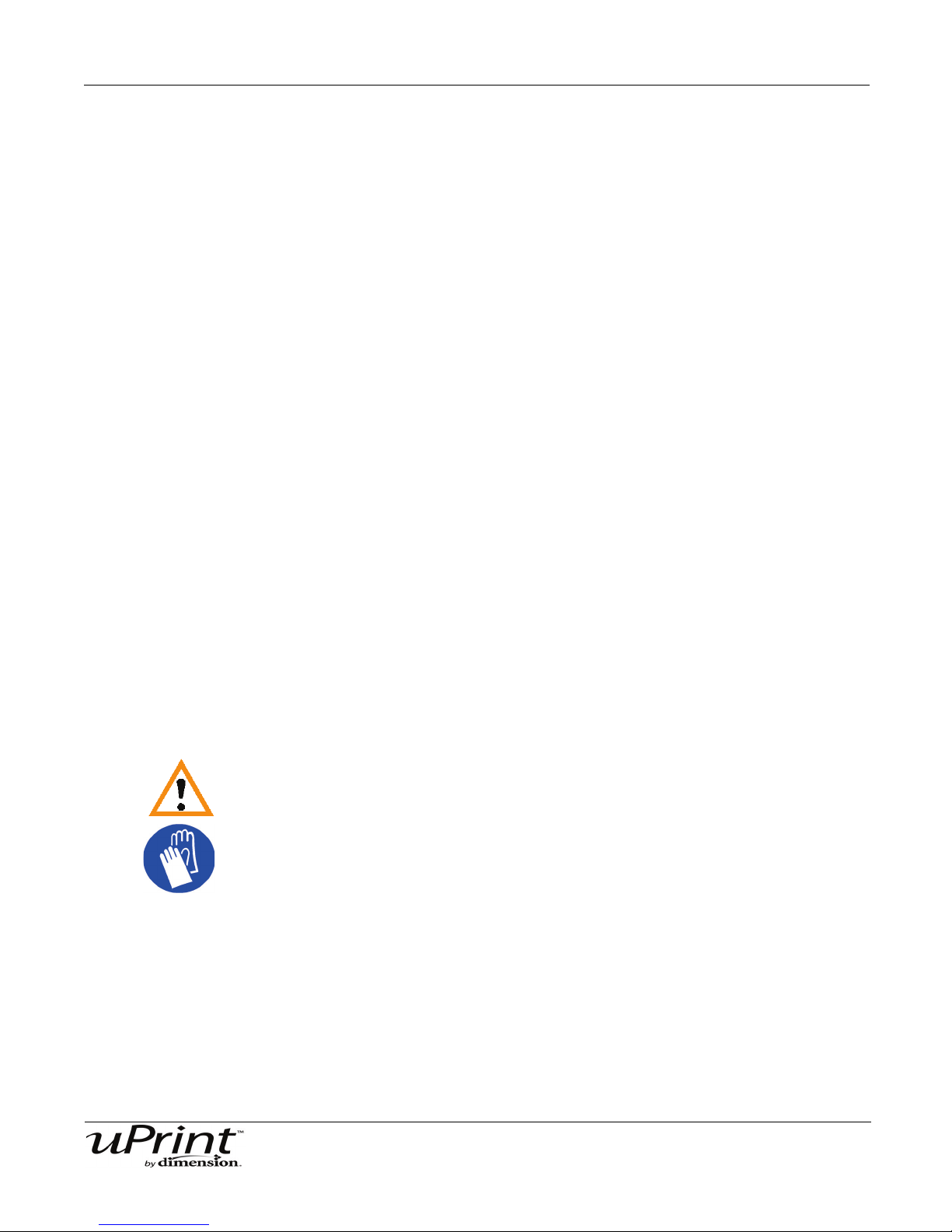
Troubleshooting and Maintenance 53
11. After approximately 5 seconds, reduce pressure against the toggle spring and allow the idler wheel to
contact the material. Material should extrude from the clogged tip.
Note:
The blower will automatically turn on in 10 seconds.
12. Press Stop on the interface panel.
13. Move the toggle bar to activate the drive wheel control options for the non-clogged side.
14. Press Forward on the interface panel. Make sure that material extrudes from the non-clogged extrusion tip.
Note:
It is necessary to confirm proper operation of the non-clogged
side. Temporarily having the blower off can occasionally cause
the non-clogged side to clog.
15. Press Stop on the interface panel.
16. Install plastic head cover.
17. Exit Maintenance mode.
Recovering From Loss of Extrusion
Note:
It is recommended that you read and understand this entire
procedure before performing any of the work.
1. Enter Head Maintenance mode.
A. From Idle, press Maintenance.
B. Press Next.
C. Press Head Maintenance.
WARNING
The head area is hot. Use leather gloves when working in this area of printer.
2. Remove plastic head cover.
• Remove plastic head cover by squeezing raised pads on sides of cover. See Figure 38.
3. Place the tip toggle bar in neutral position (bar will extend equally from both sides of head). This can be
done manually - push on the extended bar end.
Stratasys Document Number 206465-0001

Troubleshooting and Maintenance 54
Figure 32: Tip Toggle Bar in Neutral Position
CAUTION
The end of the extrusion tip where the material enters is called the Extrusion
Tube. Extrusion Tubes are fragile. Use care when working in this area so as
to avoid damage to the tubes.
4. Remove excess material found around the head area.
Note:
Material fed to the tip can sometimes jam causing a build-up of
material under the head cover.
A. Clean out as much of the material as possible using needle nose pliers, a probe, or equivalent tool.
B. To facilitate access to areas that may need to be cleaned, move the material idler wheels out of
the way (there is one idler wheel for support material and one for model material illustrates the
model side):
Note:
Move only one idler wheel assembly at a time. Finish cleaning
around the moved wheel and restore it to its normal position
before moving the other idler wheel. Having both wheels out of
position simultaneously could stretch the spring.
i. Using a 7/64 T-handled hex driver (from Start-Up Kit) to leverage against the lower idler wheel
shaft, push the idler assembly away from the Material drive gear by pushing against the spring
tension. See Figure 31.
Note:
When moving the idler wheel assembly, you can obtain maximum
clearance for cleaning if you also move the Tip Toggle Bar so that
it is extended to the same side of the head assembly as the one
on which you are working. It is not necessary to keep Toggle Bar
in a neutral position.
Stratasys Document Number 206465-0001

Troubleshooting and Maintenance 55
ii. Insert 1/8 T-handled hex driver (from Start-Up Kit) into the fixture hole.
iii. Ease pressure on the 7/64 T-handle driver to carefully return the leveraged idler wheel back
toward its original position - until the idler assembly is resting against the 1/8 T-handled hex
driver.
iv. Remove the 7/64 T-handled driver used to leverage the idler assembly.
v. Clean the area that is now accessible. Remove the 1/8 T-handle hex driver when complete.
6. Remove excess material from the top of the liquefier.
• Use needle nose pliers to carefully grip and remove excess material from the top of the liquefier.
7. Snip the material line from the cartridge close to the drive wheel.
8. Make sure that all loose material is removed from the affected extrusion inlet area.
9. Check for loose material in the other extrusion inlet area. Clean the area as necessary.
Cycling Power
To cycle power to the printer:
1. Turn the power switch to the OFF position. The display will show Shutting Down.
2. After the printer has cooled down enough to shut down, the display will go blank.
3. When the display is blank and the printer has shut down, turn the circuit breaker to the OFF position.
4. Once the circuit breaker has been turned to the OFF position, wait 30 seconds and turn the circuit
breaker back to the ON position.
5. Turn the power switch to the ON position. The printer display will show that it is starting up.
Once the display shows Idle or Ready to Print, you can send a file to the printer to be printed.
Stratasys Document Number 206465-0001

Troubleshooting and Maintenance 56
Tip Wipe Assembly
The tip wipe assembly should be replaced approximately every 500 hours.
Replacing the tip wipe assembly:
(Refer to.
1. Completely power down the printer. See “Powering off” on page 45.
2. Move the Toggle Head to the right of the printer to gain access to the tip wipe assembly.
Figure 33: Move the Toggle Head to the right
3. Remove the tip wipe assembly by lifting the assembly up and out of the printer. Discard this tip wipe
assembly.
Figure 34: Replacing the tip wipe assembly
4. Place the new tip wipe assembly over the two mounting posts making sure the assembly is fully
seated.
Stratasys Document Number 206465-0001

Troubleshooting and Maintenance 57
Tip Shield Replacement
Tip shields can become worn or damaged over time. This can have a negative impact on the surface finish
and detail of models. Replace the tip shields every 500 hours.
Figure 35: Tip Shield Damage
1. Enter Head Maintenance.
A. From the display panel press Maintenance.
B. Press Machine.
C. Press Head. The head will come to rest in the center of the chamber and the Z Platform will
change position.
WARNING
The head area is hot. Use gloves when working in this area of printer.
2. Position the blade of the small screwdriver between the Tip Shield and Tip Plate.
3. Use the blade of the small screwdriver to separate the Tip Shield from the Tip Plate. See Figure 36
Stratasys Document Number 206465-0001
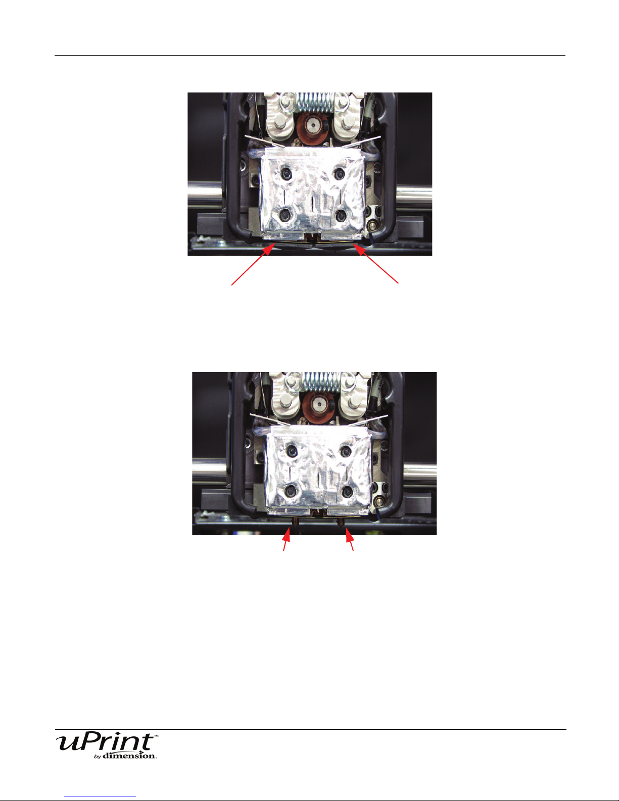
Troubleshooting and Maintenance 58
Insert small standard screwdriver to pry tip shields from tips.
Clean the tips using a wire brush.
Figure 36: Tip Shield Removal
4. Clean the tip using the wire brush supplied with the Start Up Kit to remove any debris. See Figure 37
Figure 37: Clean tips with wire brush
5. Install a new Tip Shield by pushing it, by hand, over the exposed tip, keeping the slotted end towards
the back of the tip.
6. Exit Maintenance.
Stratasys Document Number 206465-0001
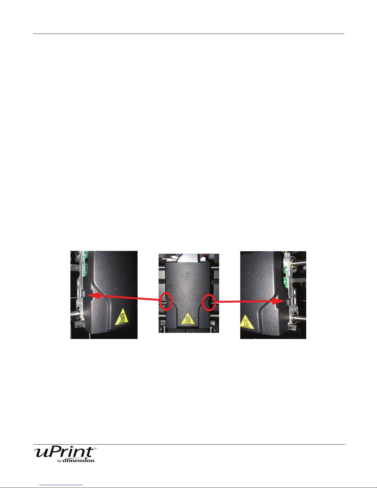
Troubleshooting and Maintenance 59
Press clips in and pull head cover out
Extrusion Tip Replacement and Calibration
Replace Tips at approximately 2000 hours.
Note:
Tips can also be damaged by improper care while performing
maintenance in the area around the tips.
CatalystEX displays the tip time (hrs) - from the Printer Services
Tab - Printer Info button (Tip time will reset to zero after
replacement).
Removing Tips:
1. You will need to make sure the printer is powered ON before replacing the extrusion tips.
2. From the display panel press Maintenance.
3. Press Machine.
4. Press Tip.
5. The printer will display Load Model - Unloading.
6. After the temperature has stabilized, the printer will display Tip Maintenance - Replace Tips. You can
now open the printer door and replace the tips - or you can Cancel the tip replacement procedure.
7. Remove plastic head cover by squeezing raised pads on sides of cover.
Figure 38: Removing the Head Cover
8. Remove Tips
A. Use 7/64 T-Handle Allen wrench to loosen the tip screws three to four full turns counterclockwise -
or until the top of the screws are flush with the metal cover. DO NOT remove the screws entirely.
See Figure 39.
Stratasys Document Number 206465-0001

Troubleshooting and Maintenance 60
Loosen but do
not remove
Loosen but do
not remove
Pull tips down to
remove
Figure 39: Tip Removal
B. Use needle nose pliers to grasp the stainless steel shield of the tip.
C. Pull the tip shield toward you, then pull down to remove the tip. Discard the used tip. See Figure
40.
Installing Tips:
1. For uPrint 3D Printer, you must identify the correct replacement tip. You must make sure a SUPPORT
Figure 40: Remove the tips
D. Repeat for second tip if necessary.
tip is used on the LEFT side of the head assembly. A MODEL tip must be used on the RIGHT side of
the head assembly (See Figure 41). The Model tip comes in a red capped container. The Support tip
comes in a black capped container.
Stratasys Document Number 206465-0001

Troubleshooting and Maintenance 61
Support Tip
Model Tip
Left Side
Right Side
Tighten screws
Tighten screws
Push tips into
position
Figure 41: Identifying Tips
2. Place the tip shield on the tip.
3. With gloved hand, insert the new tip into the heater block. The slotted side towards the rear of the
printer.
4. Use needle nose pliers to grasp the stainless steel shield of the tip.
5. Pull the tip shield toward you, then lift up to install the tip.
6. Push the tip toward the back of the printer once it is all the way up against the heater block.
7. Verify the tip is fully inserted into the heater block and that the stainless steel shield is aligned (See
Figure 42).
8. Use 7/64 T-Handle Allen wrench to firmly tighten the heater block clamp screws.
Note:
Make sure the tip remains all the way up against the heater block
as you tighten the screws.
Figure 42: Installing tips
Stratasys Document Number 206465-0001

Troubleshooting and Maintenance 62
9. Repeat steps 3 through 8 for the other tip if necessary.
10. Replace Plastic Head Cover and close the printer door.
11. The printer will display Tip Maintenance - Tips Replaced? - press Yes to begin material load.
A. The printer will display Load Model - Replace Both Carriers (flashing).
• If you want to replace a material carrier, do so now (See “Installing a spool of material into the carrier:”
on page 29 and “Adding material carriers to the single material bay” on page 31
• If you do NOT want to change a material carrier, you must unlatch and latch the carriers to continue
(Press the carrier forward to unlatch, then press it forward again to latch).
Note:
Because the material ‘unloaded’ during the tip replacement, the
printer is in a material replacement mode. You must unlatch and
then latch the carriers to continue.
If there is a delay in the unlatch/latch process, the printer will
display Both Carriers Not Replaced Or Invalid. Select Retry,
then unlatch and latch the carriers.
B. The printer will now begin to load material. See “Installing a spool of material into the carrier:” on
page 29 and “Adding material carriers to the material bay:” on page 31.
C. After material Loading is complete the printer will display Tip Calibration - Install Modeling Base
And Build Calibration Part.
Note:
Make sure a NEW modeling base is installed before starting
calibration. Calibration results will be incorrect if a NEW modeling
base is not used.
Tip Calibration:
Tip Replacement requires that Tip Calibration be performed.
1. Select Start Part (flashing) - the printer will run two calibration parts.
• The printer will automatically build a Z Calibration part, measure the part and calibrate the Z Axis for tip
depth and tip level (approximately 5 minutes). The Z calibration is Automatic.
• The printer will then automatically build an XY Calibration part (approximately 10 minutes). You must
inspect the XY Calibration part and calibrate the X and Y axes for tip offset:
2. When the XY Calibration part is complete the printer will display Remove Part and Select XY Adjust-
ment - X:0, Y:0
3. Remove the XY tip calibration part from the printer.
4. Inspect the part and calibrate the X and Y axes (See Figure 43).
A. Use the magnifier from the Startup Kit to view the support road (shown in red).
B. Identify the location on the +X or –X side of the part where the support road is best centered within
the model boundaries (shown in blue).
C. Read the number closest to this location. This is the required X Tip Offset adjustment, in mils. If the
number is on the -X side, a negative offset is required.
Stratasys Document Number 206465-0001
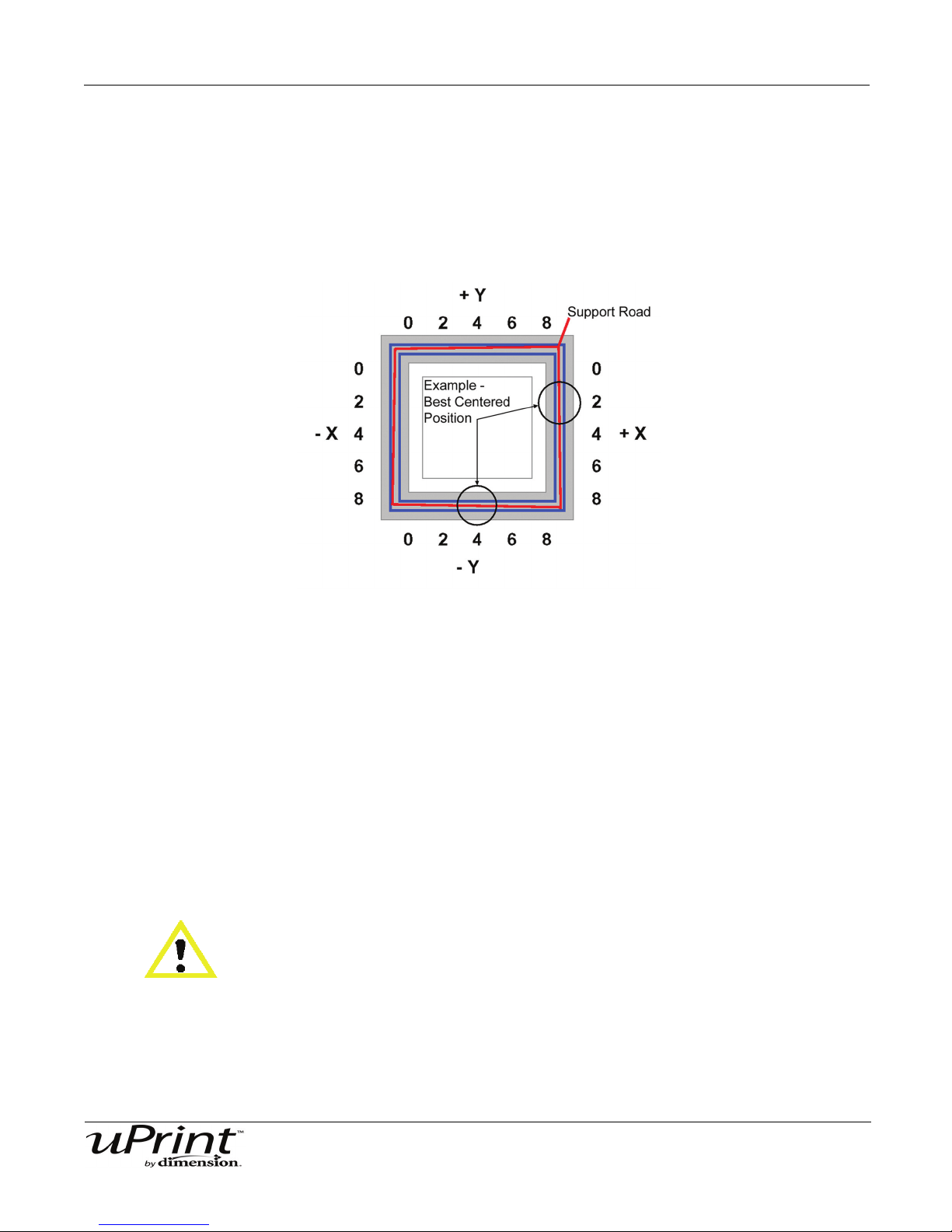
Troubleshooting and Maintenance 63
D. Select Increment or Decrement to input the X offset adjustment - the value will change in the
upper display window (by default, the printer will be ready to accept the X value).
E. When you are satisfied with your X offset value, Select Y and repeat steps A- D to identify and
input the required Y Tip Offset adjustment.
5. Select Done after you have input the X and Y offsets. The printer will return to Maintenance. Run the
XY calibration a second time to be sure the values changed the offset properly.
Figure 43: Example XY Tip Offset Part.
This example requires an adjustment of X = + 2 mils, Y = - 4 mils
Remove Debris Buildup
Remove all material buildup on the Z Platform and around the lead screw. Failure to do so could cause the
base to not be level or the Z Platform to jam at its upper limit.
Vacuum Build Chamber
Vacuum the build chamber to remove all debris and purged material.
Clean Door
Do not use glass cleaner on the door. It will damage the acrylic window.
CAUTION
ONLY use acrylic cleaner.
Stratasys Document Number 206465-0001

Troubleshooting and Maintenance 64
Chamber Light Bar
Replace chamber light bar:
1. Power down the printer.
2. Locate the wiring harness leading away from the bottom of the light bar.
3. Disconnect the light bar from the wiring harness by squeezing the wiring harness clip while pulling
down.
4. Remove the light bar by removing the 3 attachment screws (top, middle, bottom) - use the 7/64 T-handle wrench supplied in the Startup Kit.
5. Install a replacement light bar with the 3 attachment screws - do not overtighten the screws.
6. Re-attach the wiring harness lead.
Stratasys Document Number 206465-0001

Support 65
Support
Registration
To register your uPrint 3D printer, visit http://www.uprintdimension.com/productinformation/customerinfo
Customer Support
Visit http://www.uPrintDimension.com for the following:
• How to order consumable parts for your uPrint printer.
• Technical support contact information for your uPrint printer.
• Technical support for your SST tank.
• Part finishing information.
When contacting technical support please provide the following:
By phone:
• System Model.
• System Serial Number.
• System Software Build number.
• Detailed description of the problem you are experiencing.
• Please try to be near the printer for troubleshooting, if possible.
By email:
• System Model.
• System Serial Number.
• Your Name.
• Your telephone number.
• Detailed description of the problem you are experiencing.
For advanced troubleshooting (provide by email):
• System CFG file.
• STL and/or CMB files.
• Detailed photographs showing the issue.
Stratasys Document Number 206465-0001
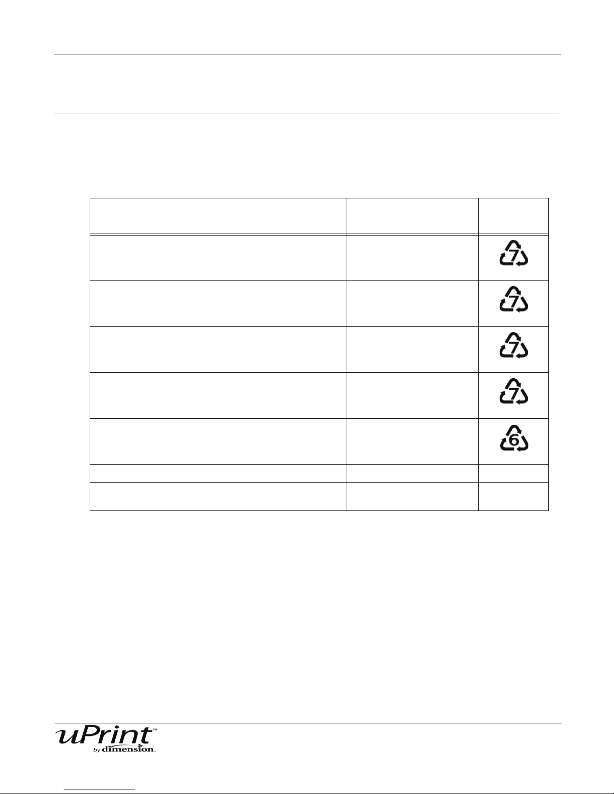
Recycling 66
Recycling
Recycle all materials per your local recycling guidelines.
Table 1: Material properties
System Component Materials
Model material guide (red, both halves) ABS
Material retaining clip (yellow) ABS
Support material guide (black, both halves) ACETAL
Recycling
Code
Material Carrier (clear top, black bottom and bottom
cover. Latches, hinge pin and electronics not included)
Material Spool & lid (gray) PS - HI
EEproms Electronics
All cardboard can be recycled per your local recycling
guidelines.
PC
Stratasys Document Number 206465-0001

Recycling 67
Pry apart with a small standard
screwdriver
Pry apart with a small standard
screwdriver
Follow your local recycling guidelines when recycling electronic components.
Removing the EEproms from the material guides
1. Open the model and support material carriers and remove the material guides.
2. With a small standard screwdriver, pry the two material guide halves apart. See Figure 44 and Figure
45.
Figure 44: Pry the model material guide apart
Figure 45: Pry the support material guide apart
3. Recycle the EEPROM per your local electronics recycling guidelines.
4. Recycle the material guides per your local guidelines. See Table 1 on page 66.
Stratasys Document Number 206465-0001

Recycling 68
Eden Prairie, MN 55344-2080 USA
7665 Commerce Way
http://www.uPrintDimension.com
Stratasys Document Number 206465-0001
 Loading...