

Page 1

Feature
Descriptions
© COPYRIGHT 1992 TOSHIBA AMERICA INFORMATION SYSTEMS, INC.
All rights reserved. No part of this manual may be reproduced in any form or by any
means—graphic, electronic, or mechanical, including recording, taping, photocopying, or
the use of information retrieval systems—without express written permission of the
Page 2

p
STRATA
TRADEMARKS AND SERVICE MARKS
The following trademarks and service marks are used in this manual:
■ STRATA®: registered trademark of Toshiba America Information Systems, Inc.
In accordance with U.S. Copyright Law, a license may be required from the American Society of Composers,
Authors and Publishers, or other similar organization, if radio or television broadcasts are used for the Musicon-Hold feature of this telecommunications system. Toshiba America Information Systems, Inc. disclaims
any liability arising out of the failure to obtain such a license.
Certain state and federal laws regulate the monitoring of calls without the knowledge of parties involved.
Prior to performing any method of call monitoring, any such regulations should be identified and complied
with. Toshiba Amer ica Information Systems, Inc. disclaims any liability arising out of the failure to comply
with such regulations.
Toshiba America Information Systems, Inc. reserves the right to change any of this information including, but
not limited to, product characteristics and operating specifications, without prior notice.
Page 3

STRATA
SUBJECT PAGE
SYSTEM OVERVIEW
Description......................................................................................................................................... 1-1
System Capacities............................................................................................................................. 1-2
Feature Availability............................................................................................................................. 1-3
STATION EQUIPMENT
Station Availability.............................................................................................................................. 2-1
Electronic Telephones........................................................................................................................ 2-2
Digital Telephones.............................................................................................................................. 2-8
Data Interface Units........................................................................................................................... 2-12
Door Phone/Monitor Station............................................................................................................... 2-14
Standard Single Line Telephone........................................................................................................ 2-16
Voice Mail Ports and Other Devices................................................................................................... 2-18
Electronic DSS Console..................................................................................................................... 2-19
Digital DSS Console .......................................................................................................................... 2-23
SYSTEM FEATURES
1A2 Key System Interface................................................................................................................. 3-1
Account Codes
..................................................................................................................................3-2
Alarm Sensor ...................................................................................................................................
3-
4
Alternate Point Answer......................................................................................................................3-5
Amplified Conference........................................................................................................................ 3-6
Automated Attendant......................................................................................................................... 3-7
Automatic Hold/Automatic Release (Hold/Split)................................................................................ 3-8
Automatic Hold Recall....................................................................................................................... 3-9
Automatic Release from Hold............................................................................................................ 3-10
Automatic Station Relocation............................................................................................................ 3-11
Auxiliary Device Interface.................................................................................................................. 3-13
Background Music with Station Control............................................................................................. 3-14
Busy Station Ringing......................................................................................................................... 3-15
Centrex/PBX Compatibility................................................................................................................ 3-16
Centrex Ringing Repeat.................................................................................................................... 3-17
CO Line Call Pickup Groups ............................................................................................................. 3-18
CO Line Groups ................................................................................................................................ 3-19
CO Line Queuing .............................................................................................................................. 3-20
Conferencing..................................................................................................................................... 3-21
Credit Card Calling ("0 +" Dialing)..................................................................................................... 3-23
Data Switching .................................................................................................................................. 3-24
Delayed Ringing................................................................................................................................ 3-25
Direct Inward System Access (DISA)................................................................................................ 3-26
Distinctive CO Line/Intercom Ringing................................................................................................ 3-27
Door Lock Control ............................................................................................................................. 3-28
Door Phones ..................................................................................................................................... 3-29
DSS Console..................................................................................................................................... 3-30
DTMF and Dial Pulse CO Line Compatible....................................................................................... 3-31
DTMF Signal Time Continuous......................................................................................................... 3-32
DTMF Signal Time Setting................................................................................................................ 3-33
Page 4

TABLE OF CONTENTS STRATA
SUBJECT PAGE
SYSTEM FEATURES (cont.)
Flexible Line Ringing Assignment..................................................................................................... 3-39
Flexible Slot Assignment................................................................................................................... 3-40
Least Cost Routing............................................................................................................................ 3-41
Live System Programming................................................................................................................ 3-42
Memory Protection............................................................................................................................ 3-43
Message Waiting............................................................................................................................... 3-44
Multiple Simultaneous Handsfree Intercom Paths ............................................................................ 3-45
Music-on-Hold Interface.................................................................................................................... 3-46
Music-on-Hold Source....................................................................................................................... 3-47
Night Ringing Answer Code.............................................................................................................. 3-48
Night Ringing over External Page..................................................................................................... 3-49
Night Ringing over Selected Page Zones.......................................................................................... 3-50
Night Transfer (Day/Night Modes)..................................................................................................... 3-51
Non-blocking Dialing ......................................................................................................................... 3-52
Off-premises Line.............................................................................................................................. 3-53
Off-premises Station ......................................................................................................................... 3-54
Outgoing Call Restriction .................................................................................................................. 3-55
Paging—All Call Voice Page ............................................................................................................. 3-56
Paging—External Page Interface...................................................................................................... 3-57
Paging—External Zone Paging......................................................................................................... 3-58
Paging—Group Paging...................................................................................................................... 3-59
Pooled CO Lines............................................................................................................................... 3-60
Power Failure Transfer....................................................................................................................... 3-61
Privacy/Non-privacy Option............................................................................................................... 3-62
Relay Service for External Page or Door Lock.................................................................................. 3-63
Relay Service for Night/Hold............................................................................................................. 3-64
Remote Administration/Maintenance ................................................................................................ 3-65
Station Hunting.................................................................................................................................. 3-66
Station Message Detail Recording (SMDR)...................................................................................... 3-67
System Battery Backup Interface...................................................................................................... 3-69
System Programming Through Station............................................................................................. 3-70
System Speed Dial............................................................................................................................ 3-71
Tandem CO Line Connection (Trunk-to-Trunk).................................................................................. 3-73
Tenant Service .................................................................................................................................. 3-74
TIE Lines........................................................................................................................................... 3-75
Toll Restriction................................................................................................................................... 3-76
Toll Restriction Override Codes......................................................................................................... 3-78
Toll Restriction Override by System Speed Dial................................................................................ 3-79
Transfer Privacy................................................................................................................................. 3-80
Traveling Class of Service................................................................................................................. 3-81
Voice Mail Interface........................................................................................................................... 3-82
Voice or Tone Signaling..................................................................................................................... 3-83
Wall or Table Mounting...................................................................................................................... 3-84
STATION FEATURES
Automatic Busy Redial...................................................................................................................... 4-1
Automatic Callback (Intercom).......................................................................................................... 4-2
Page 5

STRATA TABLE OF CONTENTS
SUBJECT PAGE
STATION FEATURES (cont.)
Call Forward...................................................................................................................................... 4-6
Call Park............................................................................................................................................ 4-8
Call Pickup ........................................................................................................................................ 4-9
Call Transfer with Camp-on............................................................................................................... 4-10
Centrex/PBX Feature Buttons........................................................................................................... 4-11
Direct Station Selection (DSS) Buttons............................................................................................. 4-12
Distinctive LED Indicators ................................................................................................................. 4-13
Distinctive Station Ringing................................................................................................................. 4-14
Do Not Disturb................................................................................................................................... 4-15
Do Not Disturb Override.................................................................................................................... 4-16
DP/DTMF Mode Change (Tone Button)............................................................................................ 4-17
Exclusive Hold................................................................................................................................... 4-18
Executive Override (Break-in) ........................................................................................................... 4-19
Flash Button...................................................................................................................................... 4-20
Handsfree Answerback on Intercom................................................................................................. 4-21
Hearing Aid Compatible .................................................................................................................... 4-22
LCD—Alphanumeric Messaging....................................................................................................... 4-23
LCD—Busy Station Messaging......................................................................................................... 4-24
LCD—Called Station Messaging....................................................................................................... 4-25
LCD—Calling Station Messaging...................................................................................................... 4-26
LCD—Remote/Group Station Messaging ......................................................................................... 4-27
LCD—Automatic Callback Number Display ...................................................................................... 4-28
LCD—Busy Lamp Field (BLF) Indication .......................................................................................... 4-29
LCD—Call Duration Display.............................................................................................................. 4-31
LCD—Call Forward Source/Destination Display............................................................................... 4-32
LCD—Calling/Called Number Display............................................................................................... 4-33
LCD—Clock/Calendar Display.......................................................................................................... 4-34
LCD—CO Line Identification............................................................................................................. 4-35
LCD—Dialed Number Display........................................................................................................... 4-36
LCD—Feature Prompting with Soft Key Operation........................................................................... 4-37
LCD—Intercom Name/Number Display ............................................................................................ 4-38
LCD—Message Waiting Station Display........................................................................................... 4-39
LCD—Recalling Station Identification ............................................................................................... 4-40
LCD—Speed Dial Memo Directory Dialing ....................................................................................... 4-41
LCD—Station Identification............................................................................................................... 4-42
LCD—Timed Reminders................................................................................................................... 4-43
Message Waiting/Flash..................................................................................................................... 4-44
Microphone Control Button ............................................................................................................... 4-45
Modular Handset and Line Cords ..................................................................................................... 4-46
Modular Headset............................................................................................................................... 4-47
Off-hook Call Announce.................................................................................................................... 4-48
On-hook Dialing ................................................................................................................................ 4-49
Pooled CO Line Buttons.................................................................................................................... 4-50
Privacy Button................................................................................................................................... 4-51
Privacy Release Button..................................................................................................................... 4-52
Privacy Override................................................................................................................................ 4-53
Private CO Lines............................................................................................................................... 4-54
Page 6

TABLE OF CONTENTS STRATA
SUBJECT PAGE
STATION FEATURES (cont.)
Repeat Last Number Dialed.............................................................................................................. 4-58
Ringing Line Preference.................................................................................................................... 4-59
Saved Number Redial....................................................................................................................... 4-60
Speed Dial Buttons ........................................................................................................................... 4-61
Station Speed Dial ............................................................................................................................ 4-62
Timed Reminder................................................................................................................................ 4-63
Toll Restriction Override Code Revision............................................................................................ 4-64
User Programmable Feature Buttons................................................................................................ 4-65
ACD/MIS FEATURES
Description............................................................................................................................................. 5-1
ACD System Features........................................................................................................................... 5-3
Overview ........................................................................................................................................... 5-3
After Call Work Time......................................................................................................................... 5-3
After Shift Service ............................................................................................................................. 5-3
Call Distruibution............................................................................................................................... 5-3
Data Collection and Reporting .......................................................................................................... 5-3
Delay Announcements and Music..................................................................................................... 5-4
Inbound Call Routing......................................................................................................................... 5-4
Overflow to Another ACD Group....................................................................................................... 5-4
Queuing............................................................................................................................................. 5-4
ACD Agent Feature............................................................................................................................... 5-5
Overview ........................................................................................................................................... 5-5
ACD CAll Status Display................................................................................................................... 5-5
Assistance......................................................................................................................................... 5-5
Auto-answer and Zip Tone................................................................................................................. 5-5
Intra-group Call Pickup...................................................................................................................... 5-5
Login/Logout ..................................................................................................................................... 5-5
Remote Login/Logout........................................................................................................................ 5-5
Ring State Preselection..................................................................................................................... 5-5
Unavailable........................................................................................................................................ 5-5
Work Unit (Stroke Count, Call Record Identifier)............................................................................... 5-6
ACD Supervisor Feature........................................................................................................................ 5-7
Overview ........................................................................................................................................... 5-7
Agent Assistance .............................................................................................................................. 5-7
Agent Monitoring............................................................................................................................... 5-7
Alarm Indication ................................................................................................................................ 5-7
MIS Access ....................................................................................................................................... 5-7
MIS Displays.......................................................................................................................................... 5-8
Overview ........................................................................................................................................... 5-8
Agent Statistics ................................................................................................................................. 5-8
Agent Status...................................................................................................................................... 5-8
Group Traffic Monitor......................................................................................................................... 5-8
Page 7

STRATA TABLE OF CONTENTS
SUBJECT PAGE
ACD/MIS FEATURES (cont.)
MIS Reports .......................................................................................................................................... 5-9
Overview ........................................................................................................................................... 5-9
Agent Performance ........................................................................................................................... 5-9
Agent Statustics ................................................................................................................................ 5-9
Delayed Call...................................................................................................................................... 5-9
Group Overflow................................................................................................................................. 5-10
Incoming Call Duration...................................................................................................................... 5-10
Lost Call ............................................................................................................................................ 5-10
Supervisor Group.............................................................................................................................. 5-10
System Status................................................................................................................................... 5-10
Work Unit (Stroke Count, Call Record Identifier)............................................................................... 5-11
INDEX ..................................................................................................................................................... Index-1
FIGURE LIST
FIGURE SUBJECT PAGE
2-1 Electronic Telephone Diagram ................................................................................................ 2-2
2-2 Digital Telephone Diagram...................................................................................................... 2-8
2-3 Integrated DIU......................................................................................................................... 2-12
2-4 Stand-alone DIU...................................................................................................................... 2-13
2-5 Door Phone............................................................................................................................. 2-14
2-6 Electronic DSS Console.......................................................................................................... 2-20
3-1 SMDR Output—Outgoing Call ................................................................................................ 3-67
3-2 SMDR Output—Incoming Call ................................................................................................ 3-68
TABLE LIST
TABLE SUBJECT PAGE
1-1 STRATA System Capacities.................................................................................................... 1-2
1-2 STRATA Features.................................................................................................................... 1-3
2-1 STRATA Station Availability Chart........................................................................................... 2-1
Page 8

System Overview
Page 9

STRATA SYSTEM OVERVIEW
SUBJECT PAGE
Description......................................................................................................................................... 1-1
System Capacities............................................................................................................................. 1-2
Feature Availability............................................................................................................................. 1-3
TABLE LIST
TABLE SUBJECT PAGE
1-1 STRATA System Capacities.................................................................................................... 1-2
1-2 STRATA Features.................................................................................................................... 1-3
Page 10
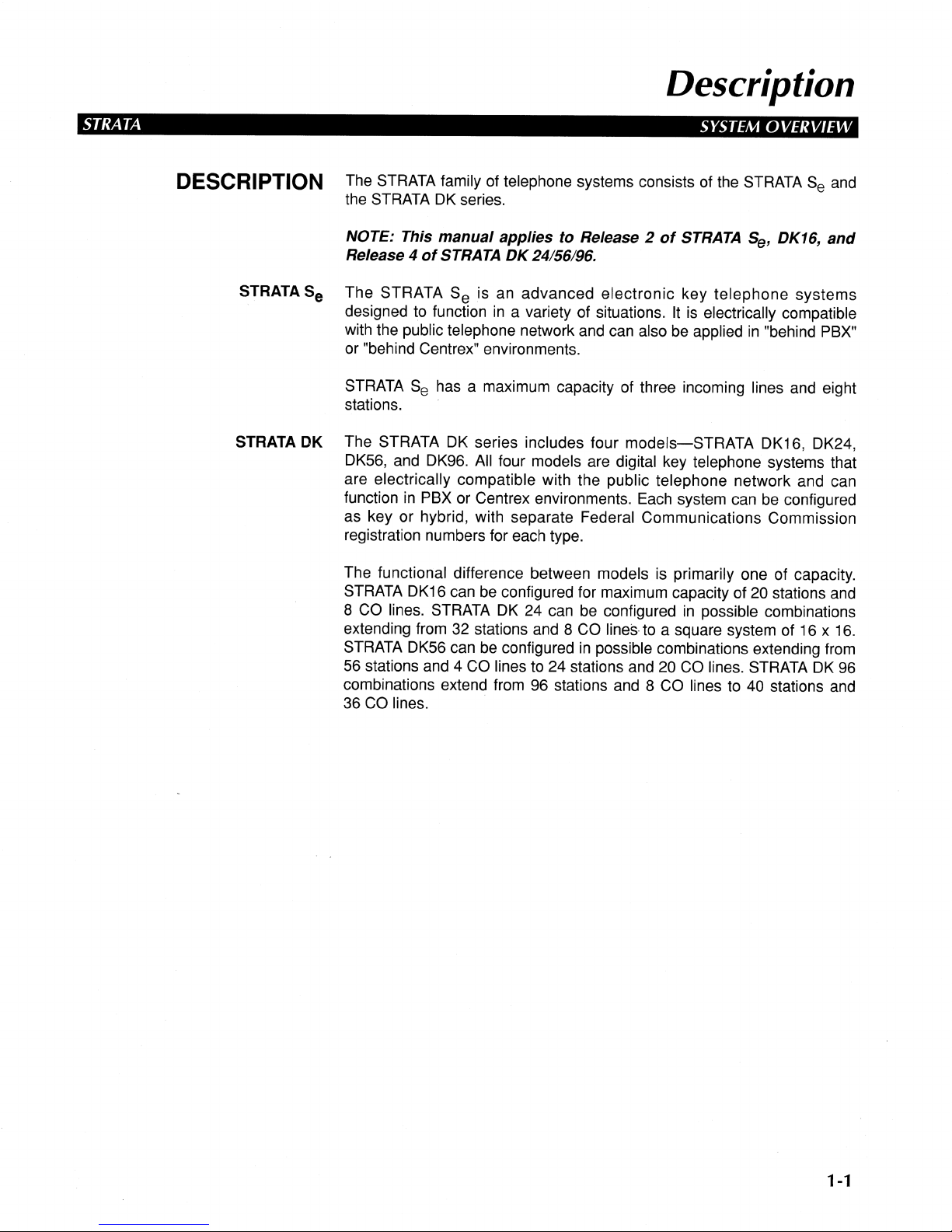
Page 11
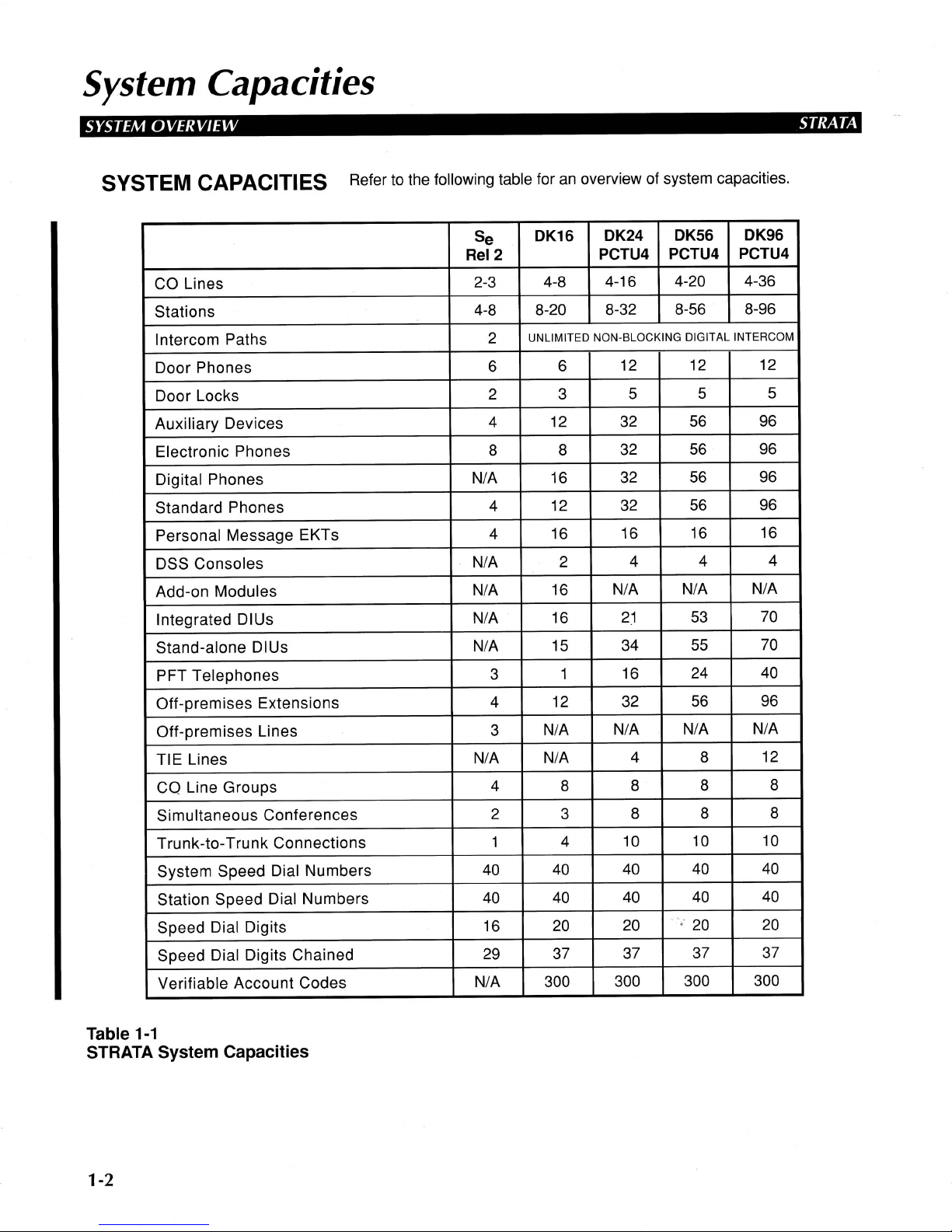
Page 12
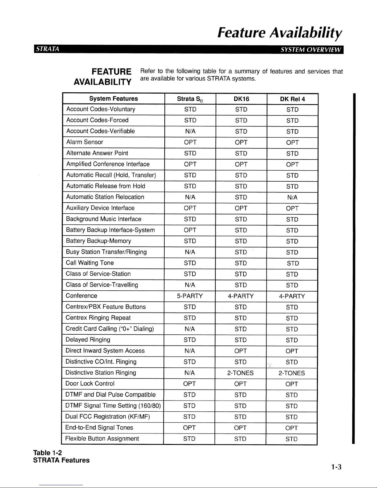
Page 13
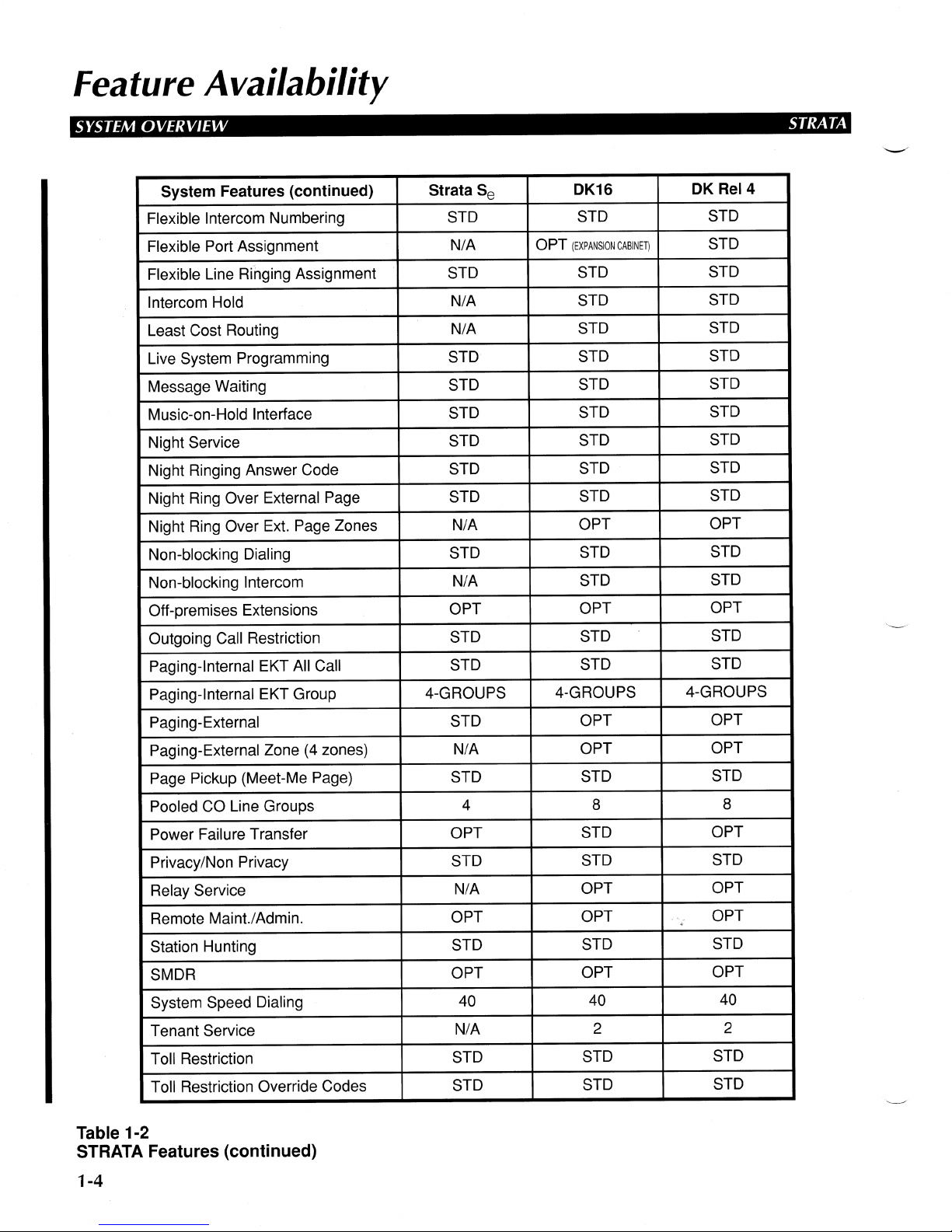
Page 14
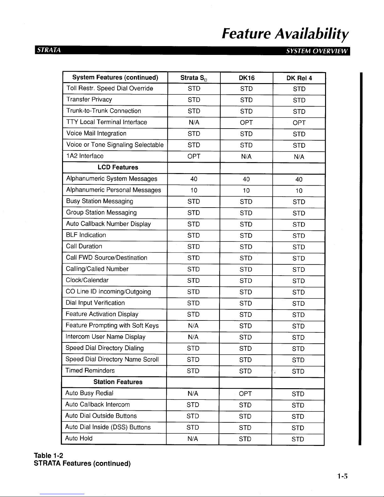
Page 15
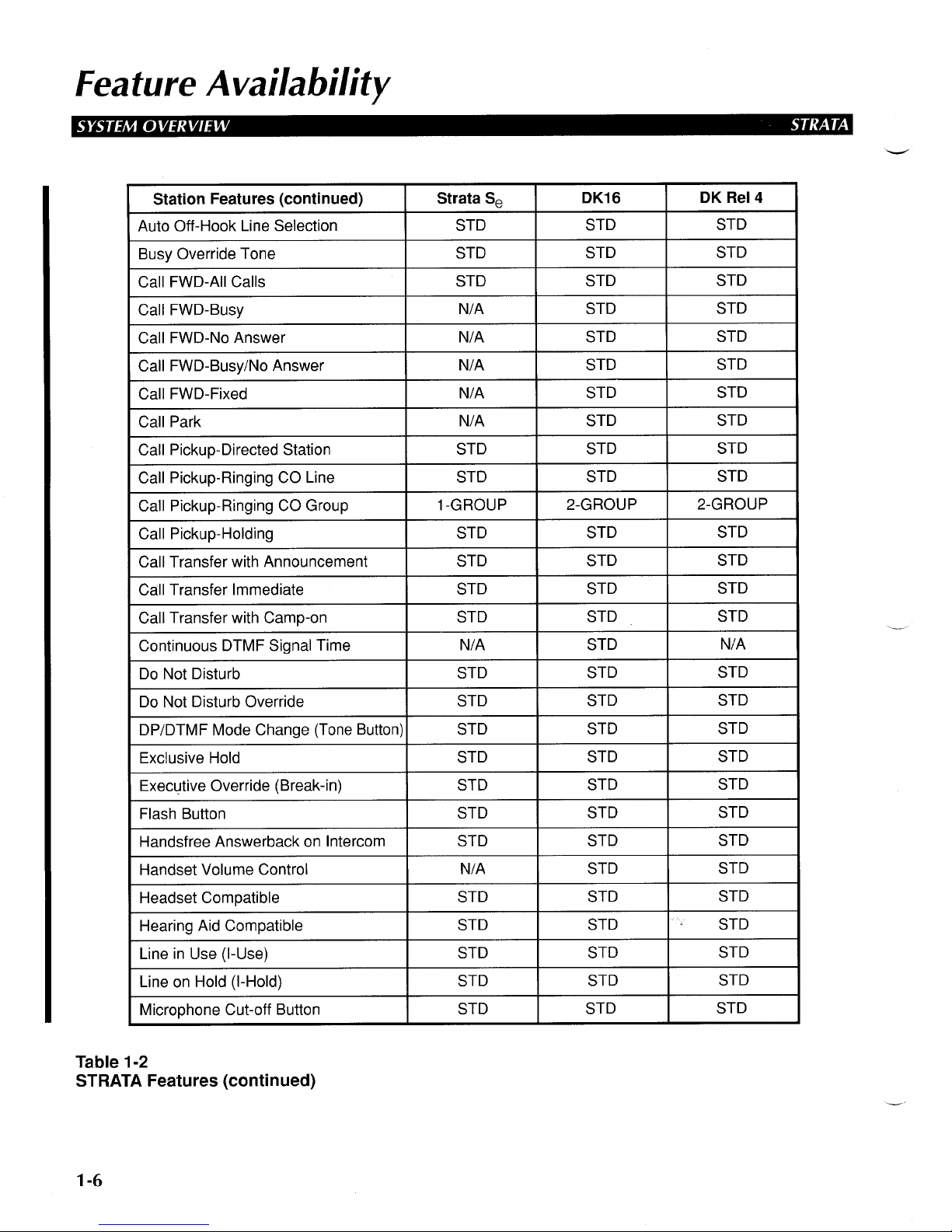
Page 16
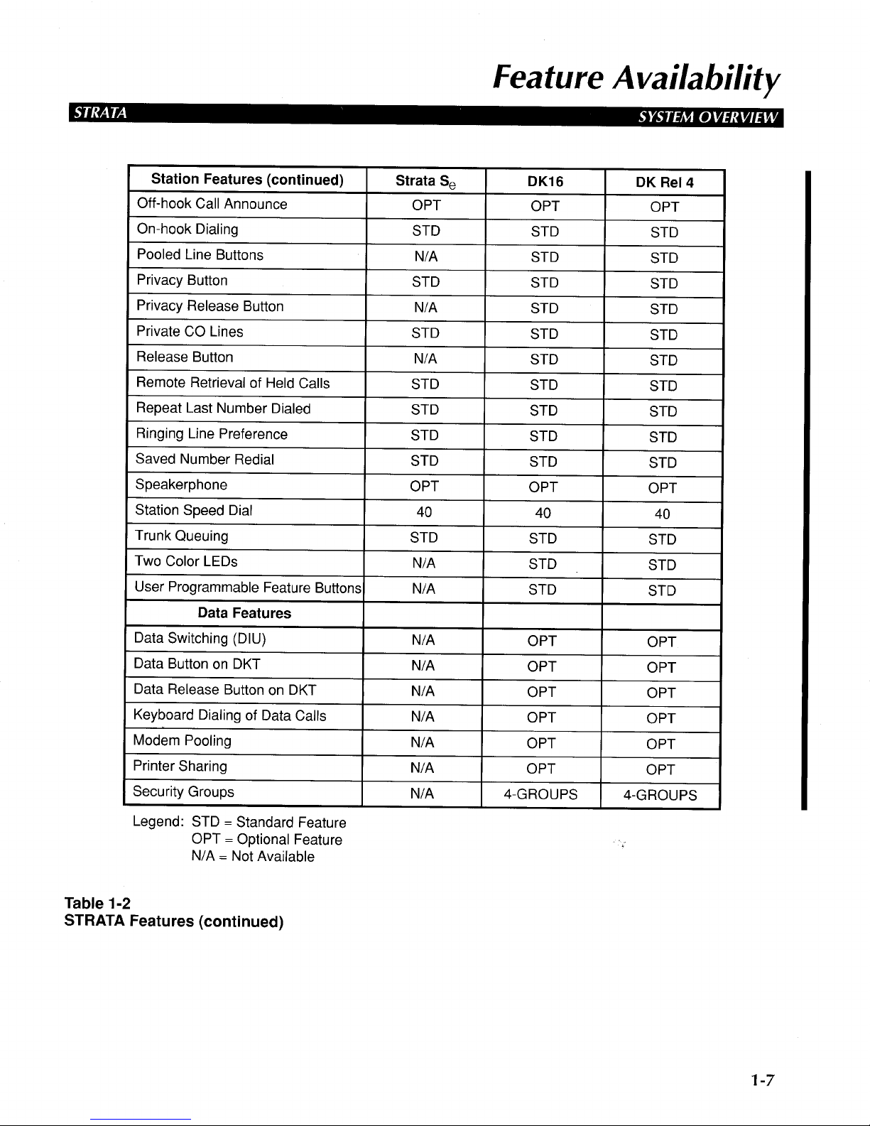
Page 17

Page 18

Station Equipment
Page 19

STRATA STATION EQUIPMENT
SUBJECT PAGE
Station Availability.............................................................................................................................. 2-1
Electronic Telephones........................................................................................................................ 2-2
Digital Telephones.............................................................................................................................. 2-8
Data Interface Units........................................................................................................................... 2-12
Door Phone/Monitor Station............................................................................................................... 2-14
Standard Single Line Telephone........................................................................................................ 2-16
Voice Mail Ports and Other Devices................................................................................................... 2-18
Electronic DSS Console..................................................................................................................... 2-19
Digital DSS Console .......................................................................................................................... 2-23
FIGURE LIST
FIGURE SUBJECT PAGE
2-1 Electronic Telephone Diagram ................................................................................................ 2-2
2-2 Digital Telephone Diagram...................................................................................................... 2-8
2-3 Integrated DIU......................................................................................................................... 2-12
2-4 Stand-alone DIU...................................................................................................................... 2-13
2-5 Door Phone............................................................................................................................. 2-14
2-6 Electronic DSS Console.......................................................................................................... 2-20
TABLE LIST
TABLE SUBJECT PAGE
2-1 STRATA Station Availability Chart........................................................................................... 2-1
Page 20
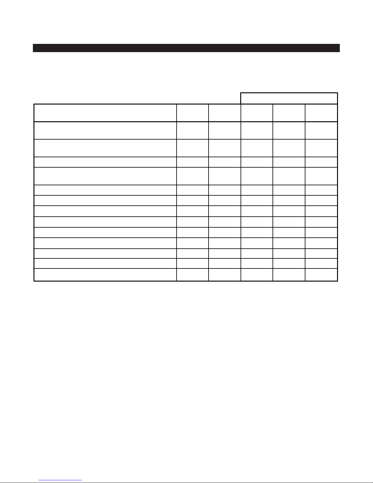
Station Availability
STRATA DK STATION EQUIPMENT
Refer to the following table for a summary of the types of station
equipment that are available for various STRATA systems.
DESCRIPTION
November 1993 2-1
2000-SERIES DIGITAL TELEPHONES
10-button Digital Telephone with Handsfree
Answerback (DKT-2010-H)
10-button Digital Speakerphone with Liquid Crystal
Display (DKT-2010-SD)
20-button Digital Speakerphone (DKT-2020-S)
20-button Digital Speakerphone with Liquid Crystal
Display (DKT-2020-SD)
ANSWER POSITION
Attendant Console
20-button Add-on Module (DADM2020)
60-button Digital DSS Console (DDSS-2060)
PERIPHERALS
Data Interface Unit Integrated (PDIU-DI2)
Data Interface Unit Stand-alone (PDIU-DS)
Door Phone/Monitor Station (MDFB)
Standard Single Line Telephone
STRATA
DK8
✓
✓
✓
✓
N/A
✓
N/A
✓
✓
✓
✓
RCTU-B
✓
✓
✓
✓
✓
✓
✓
✓
✓
✓
✓
= Equipment can be used on this system.
= Equipment is not available on this system.
✓
N/A
RCTU-A
✓
✓
✓
✓
N/A
✓
✓
✓
✓
✓
✓
RCTU-
C/D
✓
✓
✓
✓
✓
✓
✓
✓
✓
✓
✓
STRATA DK280
STRATA
DK16
✓
✓
✓
✓
N/A
✓
✓
✓
✓
✓
✓
Table 2-1
STRATA Station Availability Chart
Page 21
Digital Telephones
STATION EQUIPMENT STRATA DK
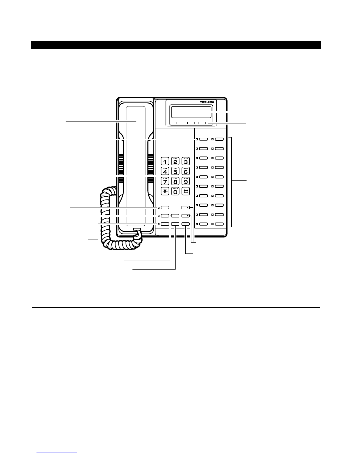
The 2000-series digital telephone is pictured below. Digital telephones can
be used on DK8, DK16, or DK280 systems. They are connected to the DK
system with a single pair modular line cord. When equipped with an
integrated data interface unit, digital telephones can transmit and receive
simultaneous voice and data.
There are four models of the 2000-series digital telephone.
This telephone is equipped with a unit that allows handsfree answerback
on intercom calls only.
This telephone has a full speakerphone and a 32-character alphanumeric
Liquid Crystal Display (LCD). All display functions occur automatically as
call processing proceeds. A description of the features of the LCD
telephone is found in the Station Features section of this manual.
This telephone has a full speakerphone, allowing two-way handsfree
conversation on both intercom and outside line calls.
DESCRIPTION
TYPES OF DIGITAL
TELEPHONES
10-button Telephone with
Handsfree Answerback
10-button Speakerphone with
Liquid Crystal Display (LCD)
20-button Speakerphone
2-2 November 1993
LCD DISPLAY
LCD CONTROL/SOFT
KEY BUTTONS
FLEXIBLE FEATURE
CONTROL BUTTONS
DIALPAD
MESSAGE WAITING
BUTTON AND LED
INDICATOR
MICROPHONE
ON/OFF BUTTON
AND LED INDICATOR
SPEAKER ON/OFF
BUTTON AND LED
INDICATOR
LAST NUMBER REDIAL BUTTON
CONFERENCE/TRANSFER BUTTON
VOLUME UP/DOWN CONTROL BUTTONS
HOLD BUTTON
HANDSET
Msg
Mic
Spkr
Redial
Cnf/Trn
Hold
Vol
Vol
Mode Page Scroll
RED/GREEN
LED INDICATORS
Figure 2-1
2000-Series Digital Telephone Diagram
Page 22

Digital Telephones
STRATA DK STATION EQUIPMENT
This telephone has a full speakerphone and a 32-character alphanumeric
Liquid Crystal Display. All display functions occur automatically as call
processing proceeds. A description of the features of the LCD telephone is
found in the Station Features section of this manual.
The push button dialing pad on the 2000-series Digital telephones is large
and easy to use. The ideal size not only provides easier operation but
minimizes dialing errors. The push button keys generate electronic signals
that are neither DTMF nor rotary. Signals sent by the phone to the KSU
are translated by the system into DTMF or rotary dial signals as required
by the serving Central Office.
Each of the line/feature keys on a digital phone has an associated twocolor LED. If a key is assigned to a CO/Centrex/PBX line, the LED
provides an indication of the status of that line. Green indicates the line or
intercom buttons you are using, and red indicates use by someone else.
(See the Station User Guide for a detailed explanation of LED signals.)
If a key is assigned to a feature, the LED indicates the status of the
feature. For example, the LED associated with the “Do-Not-Disturb” key
lights when the DND feature has been activated on the station.
LEDs are also associated with three of the six dedicated feature keys. On
the “Msg” key, a lighted LED indicates that a message is waiting for the
station. The “Spkr” LED indicates the on/off status of the speaker or
background music. The “Mic” LED indicates the on/off status of the
station’s microphone.
Two electronic volume control buttons are conveniently located below the
dialing pad on the 2000-series digital telephone. These keys adjust all
volume functions of the telephone including the ring, speaker, handset,
and muted tone burst levels.
A digital telephone is equipped with a modular handset and line cord, and
is connected to the system via 1-pair wiring.
A digital telephone can be upgraded with the integrated data interface unit
(PDIU-DI2), which enables it to transmit and receive simultaneous voice
and data. The PDIU-DI2 replaces the standard base of the digital
telephone, with a unit of the same size and shape.
To receive Off-Hook Call Announce, a digital telephone must be equipped
with a DVSU upgrade assembly, which is installed in the base of the
telephone. No special equipment is required for digital telephones to
originate Off-Hook Call Announce. (See “Off Hook Call Announce” in the
Station Features section of this manual for further details.)
To have a loud ringing bell and/or a modular headset, a digital telephone
must be equipped with the Headset Control Unit (HHEU2) upgrade
assembly. The HHEU2 mounts inside the telephone, providing a headset
20-button Speakerphone with
LCD Display
PHYSICAL CHARACTERISTICS
Dialing Pad
LEDs
Volume Controls
Modular Handset and Line Cords
Optional Hardware
November 1993 2-3
Page 23

Digital Telephones
STATION EQUIPMENT STRATA DK
jack and an interface to an external speaker amplifier (HESB) for a loud
ringing bell. A HESC-65A cable is required to connect the telephone
(HHEU2) to the external speaker (HESB).
A digital telephone that has been upgraded with a data interface unit
(PDIU-DI2) cannot be wall mounted or upgraded with the DVSU for OffHook Call Announce. The data interface unit can coexist with the HHEU2
for a headset or a loud bell, which was not possible with the previous DKT1000 digital telephone.
All digital telephones come in a stylish charcoal gray or ash white color
with a non-glare, matte finish.
A digital telephone set can be up to 1000 feet from the KSU. This may
vary according to the type of wiring used. A local external power supply
may be used to ensure 1000 feet with options.
A digital telephone can be wall mounted, unless the set has
been upgraded with a data interface unit.
All digital telephones are hearing aid compatible.
A memo tray slides out from the bottom front of the telephone, and can
hold an easy to read directory sheet.
Color
Distance from KSU
Mounting
Hearing Aid Compatible
Memo Tray
2-4 November 1993
Page 24

Digital Telephones
STRATA DK STATION EQUIPMENT
All digital telephones are equipped with six permanently dedicated feature
buttons, called fixed buttons. These six buttons are used for the following
functions:
(Speaker On/Off button with LED indicator)
Turns the speaker on and off. In on-hook dialing, can pick up line or hang
up.
(Microphone button with LED indicator)
Cuts off the microphone during speakerphone operation for private office
conversation.
(Conference and transfer button)
Used to set up conference calls and to transfer calls.
(Hold button)
Places an outside or intercom call on hold.
(Message waiting button with LED indicator)
The LED lights to indicate a message waiting. Push button to retrieve
message.
(Last Number Redial button)
Redials the last number dialed from the station.
The digital telephones also have either 10 or 20 line/feature buttons. One
of these buttons is usually assigned to the intercom function. The other 9
or 19 buttons can be assigned to a CO/PBX line or used as feature
buttons.
All 10 buttons on a 10-button set or 20 buttons on a 20-button set can be
assigned as CO/PBX keys. If the set is programmed for Automatic OffHook Selection to intercom, all keys could be used.
Any of these buttons can be assigned as a pooled line button. A pooled
line button allows a group of CO lines to “appear” under one button. Up to
four pooled line buttons per CO line group can be assigned at each
telephone. (See “Pooled Line Buttons” in the Station Features section of
this manual.)
All 10 buttons on a 10-button set or 20 buttons on a 20-button set can be
assigned as feature buttons. Digital telephones can have the following
features assigned to buttons on Strata DK systems:
■ Account Code
■ Alarm
■ All Call Voice Page
■ Alphanumeric Messaging
■ Automatic Busy Redial
BUTTON
ASSIGNMENTS
FIXED BUTTONS
Spkr
Mic
Cnf/Trn
Hold
Msg
Redial
FLEXIBLE BUTTONS
CO/PBX line keys
Feature Activation Buttons
November 1993 2-5
Page 25

Digital Telephones
STATION EQUIPMENT STRATA DK
■ Automatic Callback
■ Background Music (on/off)
■ Call Forward All Calls
■ Call Forward Busy
■ Call Forward Busy/No Answer
■ Call Forward External (DK280)
■ Call Forward Fixed
■ Call Forward No Answer
■ Call Pickup (Directed)
■ Call Pickup (Group)
■ Call Pickup 1 ~ 4 (Tenant 1 ~ 4)
■ Data
■ Data Release
■ Do-Not-Disturb
■ Door Unlock 1 ~ 5
■ Direct Station Selection
■ DTMF/Rotary Signal Selector (Tone Key)
■ “Locked” Automatic Dialing
(assigned to system auto-dial location and used for
Centrex, CO, or PBX access codes)
■ Flash
■ LCD Messaging
■ Microphone Cutoff
■ Modem
■ Night Transfer (Tenant 1 ~ 4)
■ Pause (1.5, 3, or 10 seconds)
■ Pooled Line Groups 1 ~ 16
■ Privacy
■ Privacy Release
■ Release
■ Redial Last Number (#)
■ Saved Number Redial
■ System Speed Dial Codes
■ Station Speed Dial Codes
■ Speed Dial Select (*)
■ User Programmable Feature Buttons
For ease in making key assignments, there are several standard key strip
patterns that can be programmed. Changes can then be made for the
keys on individual stations which are to be different from the standard
keystrip pattern selected for that station.
However, with the Flexible Key Assignment feature, the programmer can
define each of the 10 or 20 keys individually instead of choosing a
standard keystrip pattern and then altering it.
Any key which is not programmed for a specific feature or CO line will
remain as defined in initialization.
2-6 November 1993
Page 26

Digital Telephones
STRATA DK STATION EQUIPMENT
Some common applications for digital phones are:
■ A customer wants to transmit simultaneous voice and data, internally
or externally. See “Data Interface Unit” later in this section for details.
■ A customer wants to maximize outdialing efficiency for sales or
telemarketing groups by allowing them to use a PC keyboard auto
dialing program. The digital phone with an integrated data interface
unit enables use of such programs without a modem.
■ The customer needs handset volume control for personal comfort or to
compensate for variations in transmission quality.
■ Two-color LED indicators provide improved usage indication for
flexible buttons. Green indicates the line or intercom buttons you are
using, and red indicates use by someone else.
■ A customer wants to have the “latest and greatest” technology and
equipment, and believes that having digital telephones will best serve
the organization’s future needs.
■ The customer wants to maximize use of available buttons. The digital
key telephone has fixed keys for message waiting and last number
redial, freeing more flexible buttons for other functions.
10-Button Applications include:
1. The 10-button telephone is generally used as the basic station
telephone for people who do not require one-button access to many
features.
2. If the Pooled Line Button feature is used, 10-button telephones can
also be a cost-effective alternative to the 20-button telephone.
20-Button Applications include:
1. The customer has a requirement for several features to be
programmed for one-button access. For example, executives may
want the convenience of one-button access to the features they use.
2. Some customers may require several features that can be accessed
only by a button. In such a case, the 20-button phone may be needed
to provide the features. For example, features requiring button access
usually require an LED status indicator, and are listed below.
Alarm
*
(Alarm Reset button)
Call Forward (Call Frwd To:___)
Data Call (Data Call button)
Modem (Modem button)
DSS Buttons (DSS:____ button)
Do Not Disturb (Do Not Disturb button)
Door Unlock
*
(Unlock Door button)
DP/DTMF Mode Change (Tone Dial Select button)
Message Waiting (Msg button)
Night Transfer (Night Transfer button)
APPLICATION
November 1993 2-7
*
Does not have LED indication.
Page 27

Digital Telephones
STATION EQUIPMENT STRATA DK
Pause (for speed dial)
*
(Speed Dial Pause button)
Pause (long)
*
(Speed Dial Lng Pause button)
Privacy (Privacy on Line button)
Privacy Release (Privacy Release button)
Station Security (Microphn Cutoff button)
Saved Number Redial
*
(Save Last Number button)
*
Does not have LED indication.
3. The customer has a requirement for multiple speed dialing buttons.
Travel agents, real estate agents, purchasing managers and others
who place several calls daily to the same numbers can benefit from
having multiple automatic dialing buttons on which they can program
their most frequently called numbers for one-button access.
4. The customer wants more than 9 CO lines to appear on a station. For
example, in a company which has 14 CO lines, a 20-button telephone
at the attendant station could have appearances for all 14 CO lines.
2-8 November 1993
Page 28
Data Interface Units
STRATA DK STATION EQUIPMENT
A data interface unit (DIU) interfaces a data device to a DK8, DK16 or
DK280 digital telephone system. It provides an RS232 connection to the
data device and a modular jack for wiring to the Key Service Unit (KSU).
The function of the DIU is to convert the RS232 signal from the data
device to a Toshiba proprietary digital signal for the KSU.
There are two types of data interface units: integrated and stand-alone.
DIUs can pass data up to 19.2 kbps. DIUs are compatible with the most
commonly used “AT” commands to allow keyboard dialing of data and
voice calls using personal computers or ASCII terminals. “AT” commands
will function at up to 9600 bps.
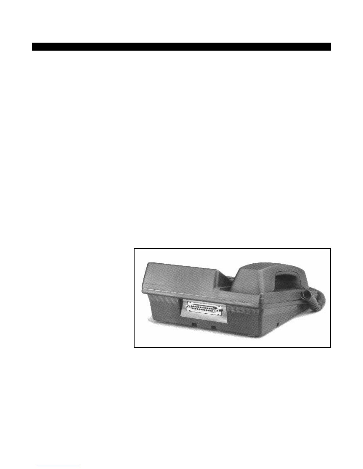
The integrated data interface unit (PDIU-DI2) (see Figure 2-3) replaces the
standard base on a digital telephone and allows the telephone to receive
and transmit simultaneous voice and data. Voice and data calls can be
made independently of each other. Asynchronous data devices, such as
personal computers and terminals, can be connected to the standard
RS232 connector in the PDIU-DI2, and can transmit and receive over the
single twisted wire pair used for the digital telephone. The PDIU-DI2 and
the digital telephone share the same wire pair and the same station port.
If a digital telephone is upgraded with the PDIU-DI2 unit, that telephone
can also be wall mounted or further upgraded with a headset or a loud
ringing bell, but not with the Off-hook Call Announce feature.
Figure 2-2
Integrated DIU
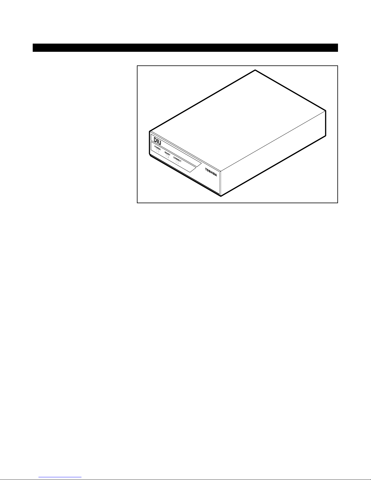
The stand-alone data interface unit (see Figure 2-4) has an RS232
connector and can interface an asynchronous RS232 data device such as
a modem, serial printer, or mainframe computer to the STRATA DK KSU.
The PDIU-DS allows switched data connections through the KSU for
modem pooling, printer sharing, and/or accessing a host or mainframe
computer. LEDs on the front panel of the PDIU-DS indicate transmission
status. Each PDIU-DS requires one digital station port on a PDKU, RDSU,
KCDU, or QCDU and will function on one wire pair.
Figure 2-3
DESCRIPTION
INTEGRATED DATA INTERFACE
UNIT (PDIU-DI2)
STAND-ALONE DATA
INTERFACE UNIT (PDIU-DS)
November 1993 2-9
Page 29
Data Interface Units
STATION EQUIPMENT STRATA DK
Stand-alone DIU
Some common applications for DIUs are:
■ Data switching enables a customer to transmit simultaneous voice and
data, internally or externally, over the same wire pair, connecting the
telephone set to the Key Service Unit (KSU).
■ A customer can maximize outdialing efficiency for sales or
telemarketing groups by allowing them to use a PC keyboard auto
dialing program. The digital phone with an integrated data interface
unit enables use of such programs without a modem.
■ Modem pooling and printer sharing can be accomplished using standalone DIUs.
■ Personal computers can exchange information interactively or make
file transfers. This can be done either internally or externally over the
public telephone network.
APPLICATIONS
2-10 November 1993
Page 30
Door Phone/Monitor Station
STRATA DK STATION EQUIPMENT
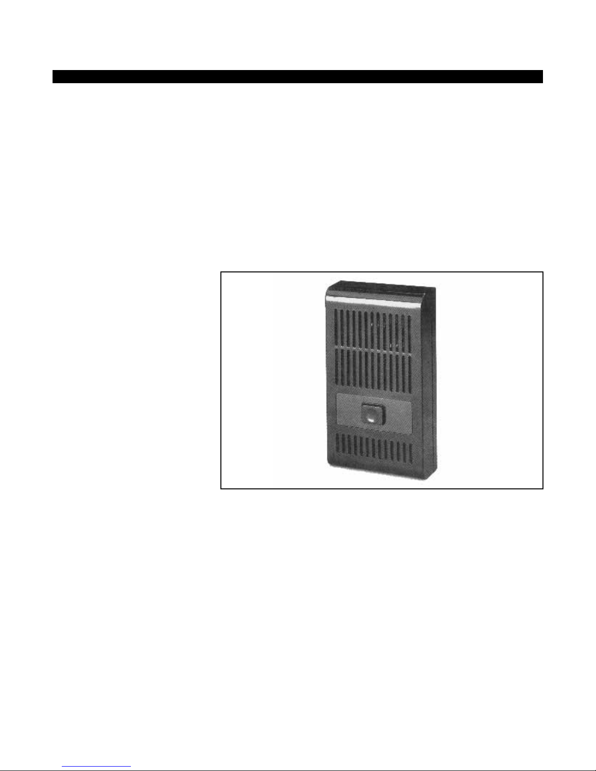
The optional Door Phone/Monitor Station (see Figure 2-5) provides a twoway intercom box. When someone presses the button on the door phone,
distinctive ringing occurs at stations which have been programmed to
receive door phone ringing. When a station answers, it is automatically
connected to the door phone and the parties can converse.
If all stations are busy when the doorphone rings, the station with the
lowest port number will be alerted with busy-override tone.
Any station in the system can dial a door phone and converse with a
person at the door phone, or simply monitor the area in which the door
phone is installed. When a station calls the door phone, no warning tone is
given at the door phone and the speech path is immediately opened.
Figure 2-4
Door Phone
The volume control is located at the back of the door phone box. Volume
adjustments can be made with a screwdriver.
Door phones are available in brown only.
The door phone/monitor station can be up to 1000 feet (24 AWG wire)
from the door phone control box (HDCB or DDCB), which is the external
module that supports the operation of the door phones. The control box
can be up to 1000 feet (24 AWG wire) from the Key Service Unit (KSU).
The door phone/monitor station is designed for wall mounting only.
Up to six door phone/monitor stations can be installed on the STRATA
DK8 and DK16. Up to 12 can be installed on a STRATA DK280 system
DESCRIPTION
PHYSICAL CHARACTERISTICS
Volume Control
Color
Distance from KSU
Mounting
Hardware
November 1993 2-11
Page 31

Door Phone/Monitor Station
STATION EQUIPMENT STRATA DK
equipped with an RCTU-B or RCTU-C/D. Up to 9 door phones can be
installed on a DK280 that is equipped with an RCTU-A.
Door phones are supported by the door phone control box external
module. Each control box supports up to three door phones, and requires
one EKT or DKT station circuit for its operation. Each door phone
connects to the control box by single pair telephone wiring.
The Door Phone/Monitor Station is primarily used at entrances to buildings
or grounds to increase security and safety. It can also be used as a
monitor station. For example, a business located in a rough area of town
may install a door phone/monitor station near the exit to the parking lot.
Employees working after hours in the building can monitor the area before
leaving the building to insure that there is no suspicious activity.
A doctors’ office uses Door Phones to communicate with examination
rooms.
The Door Phone can also serve as an inexpensive intercom station in the
remote areas of a large facility such as a warehouse.
The Door Phone can also be used with an external amplified speaker
(HESB) as a talk back speaker in an area where an EKT is not needed.
See “External Amplified Speaker” in the System Features section of this
manual for details.
APPLICATIONS
2-12 November 1993
Page 32

Standard Single Line Telephone
STRATA DK STATION EQUIPMENT
Conventional 2500-type (DTMF) or 500-type (rotary) single line telephones
can be installed on STRATA systems. These single line telephones can be
on-premises or off-premises.
Up to two single line telephones can be installed on a STRATA DK8, and
up to 12 can be installed on a STRATA DK16. A maximum of 24 can be
installed on a DK280 with an RCTU-A. A maximum of 72 on a DK280
equipped with an RCTU-B. Up to 232 single line phones can be installed
on a DK280 equipped with an RCTU-C/D.
The appearance, colors, and features of these phones depend on the
particular brand of phone used.
A single line telephone has dial code access to many of the same features
as the digital key telephones.
Automatic Off-Hook selection of a CO line is not available to the single line
telephone.
Single line telephones can be used as ACD agent phones, but Toshiba
LCD telephones are recommended.
On a STRATA DK8 system, the loop length of the single line set can be up
to 300 ohms including the telephone. On a DK16, the loop length using a
KSTU can be up to 300 ohms. On a STRATA DK16 and DK280 systems,
the loop length using an RSTU can be up to 600 ohms. If the R48S
subassembly is also used, loop length can be extended to 1200 ohms.
Single line telephones come in both desk and wall models.
On a DK8, each standard single line telephone is supported by a circuit on
the QSTU. On STRATA DK16 systems, each standard single line
telephone is supported by a circuit on the KSTU, RSTU, PSTU, or PESU.
On STRATA DK280 systems, each standard single line telephone is
supported by a standard single line circuit on an RSTU, PSTU, or
RDSU/RSTS. A DTMF receiver is also required (one per system).
There are three primary applications for standard single line telephones.
■ On all systems, the less expensive standard single line set can be
used for stations which do not require the functionality of a Digital Key
Telephone. The DK systems make this a more economical alternative,
since single line sets are supported by a circuit board (KSTU, RSTU,
or RDSU) and require no external hardware.
■ Standard single line sets are used as power failure telephones. CO
lines can be switched directly to these phones in the event of a power
failure.
■ On all STRATA systems, conventional single line sets can be used as
Off-premises Stations (OPSs), which allow stations in satellite or
remote locations to function as part of the STRATA telephone system.
See “Off-premises Station” in the System Features section of this
manual for details.
DESCRIPTION
PHYSICAL CHARACTERISTICS
Distance from the KSU
Mounting
Hardware
APPLICATIONS
November 1993 2-13
Page 33

Voice Mail Ports and Other Devices
STATION EQUIPMENT STRATA DK
On the STRATA DK systems, several types of station equipment can be
supported. These include voice mail ports, automated attendant ports,
digital announcers for ACD and built-in Auto Attendant applications,
standard single line telephones, modems, answering machines, facsimile
machines, dictation machines, and other devices. Two-wire standard
devices are supported by either a circuit on a Standard Telephone
Interface Unit. If the device requires DTMF translation, a DTMF Receiver
Unit, which mounts onto the Common Control Unit, must also be installed.
No additional external equipment is required.
DESCRIPTION
2-14 November 1993
Page 34

Digital DSS Console
STRATA DK STATION EQUIPMENT
The Direct Station Select console (DSS) is a separate unit which can be
used with a digital key telephone for a dedicated answering position. The
digital DSS console is available in the same attractive charcoal gray or ash
white color and matte finish as the other digital telephones. The digital
DSS console can be used on Strata DK systems and on Perception
e&ex
systems.
The digital DSS console is equipped with 60 buttons, each with an
associated two-color LED. Each button can be flexibly assigned as a CO
line appearance, a DSS button for one-touch dialing of a specific station,
or a speed dial number. Night Transfer and All Call Voice Page are
assigned to specific buttons on the DSS unit. If a button is assigned to a
CO/Centrex/PBX line, the LED provides an indication of the status of the
line. Green indicates the line or intercom buttons you are using, and red
indicates use by someone else. When assigned as a DSS button, the
adjacent LED shows busy status as red.
To dial a station, the attendant simply presses the DSS button assigned to
that station. It is not necessary to access an intercom line and dial the
station number. The connection is made via a DKT station associated with
the DSS console.
The STRATA DK16 can support two DSS consoles. The STRATA DK280
with RCTU-A can support three DSS consoles. The DK280 with RCTU-B
can support up to four DSS consoles. The DK280 with RCTU-C/D can
support up to eight DSS consoles. The DSS consoles are supported in the
KSU by the Digital Telephone Interface Unit (PDKU). Each digital DSS
console requires only one station port on a PDKU; one PDKU can only
support one DSS console. The DK8 does not support DSS consoles.
Digital DSS consoles can be used with any type of DKT station. However,
it is helpful to an attendant if a 20-button LCD set is installed with the DSS
unit, since the LCD will identify recalling stations, unanswered CO lines,
etc. DSS Consoles cannot be assigned to function with attendant
consoles.
1. High volume of incoming calls:
When a business has a high volume of incoming calls to a central
answering point, a DSS console speeds call processing and makes it
efficient. The DSS gives the attendant instant information on the busy
status of all extensions, and enables quick, one-touch dialing of a
station.
2. Attendant screening of calls:
Some businesses may not have a high volume of incoming calls, but
do require the attendant to spend more time on each call. For
example, some businesses want the attendant to screen all calls and
announce the caller to the called party. Screening takes additional
time, but the DSS console enables the call to be processed more
quickly once it has been screened.
DESCRIPTION
APPLICATIONS
November 1993 2-15
Page 35
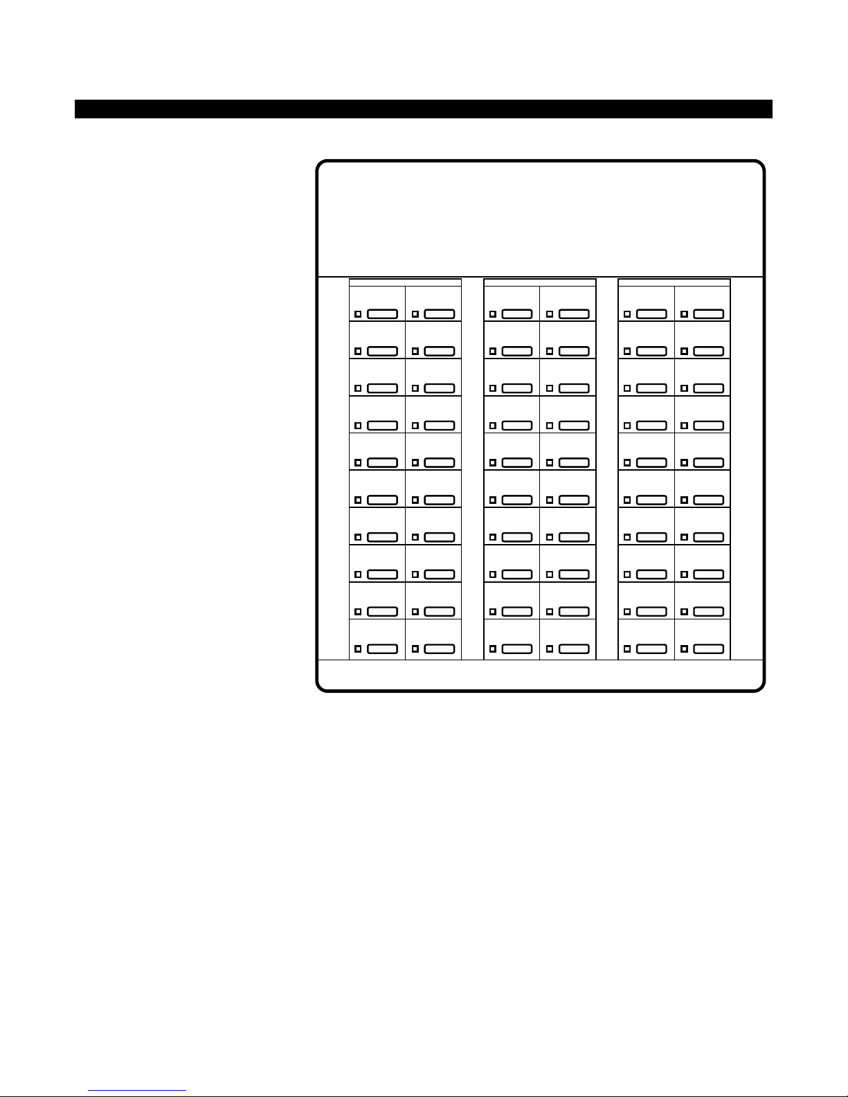
Digital DSS Console
STATION EQUIPMENT STRATA DK
2-16 November 1993
TOSHIBA
209
208
207
206
205
204
203
202
201
200
219
218
217
216
215
214
213
212
211
210
229
228
227
226
225
224
223
222
221
220
239
238
237
236
235
234
233
232
231
230
249
248
247
246
245
244
243
242
241
240
Night 1
All Call
257
256
255
254
253
252
251
250
Figure 2-5
Digital DSS Console
Page 36

Digital DSS Console
STRATA DK STATION EQUIPMENT
3. Tenant Service:
In tenant service, any combination of the four DSS consoles can be
used. For example, each tenant could have one main DSS position
and one backup DSS position. Or, one tenant could have two DSS
consoles while the other had only one.
Here are some examples of commonly used DSS console features:
DESCRIPTION: One specific button on the DSS console can be
programmed as the All Call Voice Page button (AC) and allows the
attendant to voice page all of the DKT and EKT speakers in the system
simultaneously (120 maximum for DK280). If external page is desired with
All Call Page, a user programmable button can be set up to provide quick
and easy access.
BENEFITS: This feature gives the attendant a way to reach an employee
when the employee is not at his or her desk. The customer has some
assurance that if the employee is in the building, he or she can be found
when necessary.
DESCRIPTION: A call on a CO/PBX line is automatically placed on hold
when the attendant presses a button for a specific station. The attendant
does not have to put the call on hold before pressing the DSS button. It is
recommended a Release button be programmed to use with Automatic
Hold.
BENEFITS: Automatic Hold saves time for the attendant by providing “one
button” operation for two functions: 1) putting the caller on hold and 2)
dialing the station number. It makes the process of call notification more
efficient, and allows the attendant to give better service to callers.
DESCRIPTION: Buttons on the DSS buttons can be programmed as:
All Call Page Key (Key 59 only)
Night Transfer 1 or 2 (Key 60 only)
CO Line Appearance (any of 58 keys)
DSS Button (any of 58 keys)
Personal or System Speed Dial Button (any of 58 keys)
BENEFITS: The DSS buttons can be configured to meet the specific
needs of each customer.
DESCRIPTION: One button on the DSS can be programmed as a Night
Transfer (NT1 or NT2) key. This button is used to put the system ringing in
“DAY”, “DAY2” or “NIGHT” mode. (See “Night Transfer” in the System
Features section for details about ringing modes.) If the system is installed
in tenant service, each tenant has independent control of night transfer for
its lines. Tenant 1 uses the “NT1” button, and Tenant 2 uses the “NT2”
button.
BENEFITS: With Night Transfer, incoming calls can ring at stations other
than the console, can ring over an external paging system, or can ring to
FEATURES
ALL CALL VOICE PAGE
AUTOMATIC HOLD
FLEXIBLE DSS BUTTONS
NIGHT TRANSFER BUTTON
November 1993 2-17
Page 37

Digital DSS Console
STATION EQUIPMENT STRATA DK
an answering machine when the attendant is not available. The customer
has assurance that calls can be answered at all times.
DESCRIPTION:The DSS may be programmed for tone or voice first
signaling preference, independent of how the system is programmed. As
with all stations, the attendant can choose the alternate mode by dialing a
“1” following the station number.
BENEFITS: This feature gives flexibility to the system, and allows the
attendant to use the more efficient voice signaling, even if the system is
programmed for tone signaling.
VOICE OR TONE SIGNALING
2-18 November 1993
Page 38
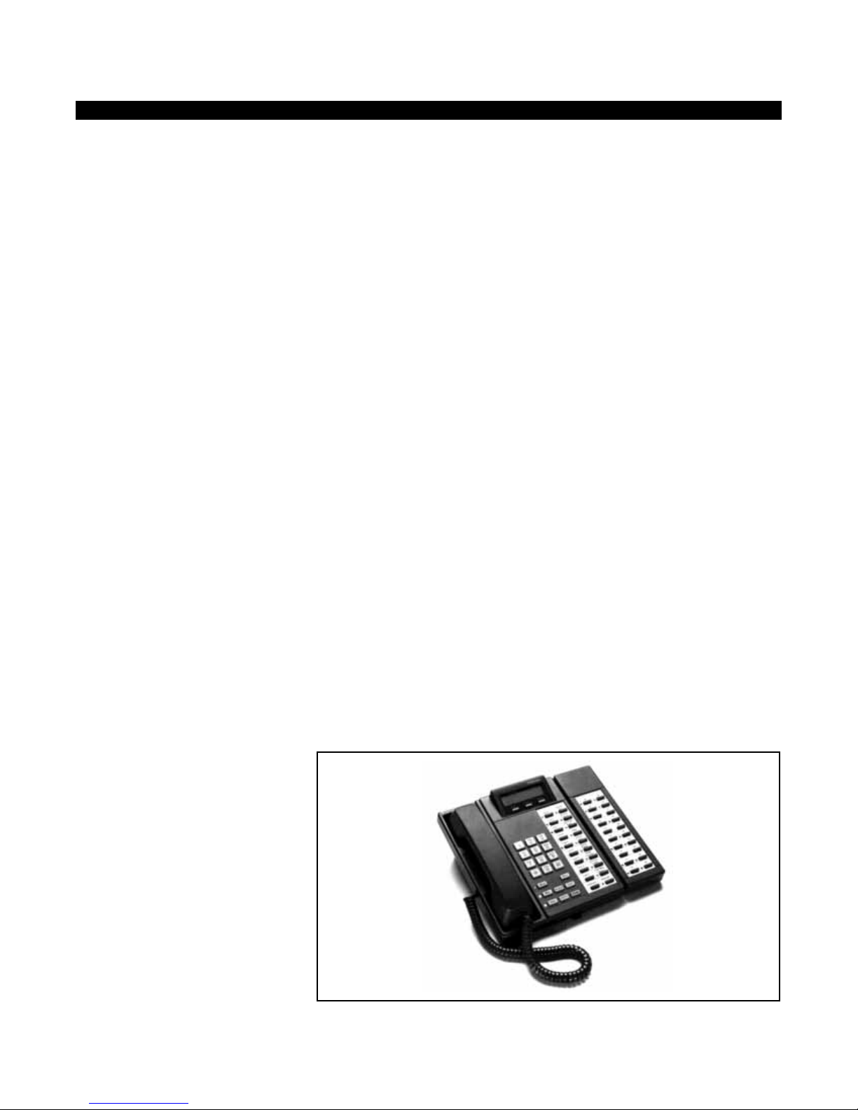
Add-on Module
The Add-On Module is a separate unit which can be used with any 2000series digital telephone for a dedicated answering position on DK8, DK16,
or DK280 systems. It does not take a separate digital station port, but
shares the one with the telephone to which it is attached.
The Add-On Module is equipped with 20-buttons, each with an associated
red/green LED. Buttons provide direct station selection (DSS) and busy
lamp field (BLF) functionality. To dial a station, the attendant simply
presses the DSS button assigned to that station. The call will
automatically be put on hold and then the connection made with the called
station. It is not necessary to access an intercom line and dial the station
number. The connection is made via the DKT station associated with the
Add-On Module.
When used on DK8 and DK280 systems, buttons on the Add-On Module
can also be programmed for CO line appearance or speed dial.
The STRATA DK8 will support up to 8 Add-On Modules. The DK16 will
support up to 16 Add-On Modules. The DK280 with RCTU-A will suppor t
up to 12 Add-On Modules. The DK280 with RCTU-B will support up to 40,
and the DK280 with RCTU-C/D will support up to 120 Add-On Modules.
On DK280 systems, either one or two Add-On Modules can be installed on
a 2000-series digital telephone. They are available in either charcoal gray
or ash white color, with a matte finish and style to match 2000-series
digital telephones.
Applications for the Add-On Module are similar to the DSS console, such
as central incoming call answering, busy status of all extensions at a
glance, one-touch dialing of stations, call screening, speed dial, and CO
line appearance.
The Add-On Module functions as a mini DSS console for small systems,
and provides a smaller, less expensive alternative to a full functioning 60button DSS Console.
Figure 2-6
Add-on Module
STRATA DK STATION EQUIPMENT
DESCRIPTION
APPLICATIONS
November 1993 2-19
Page 39
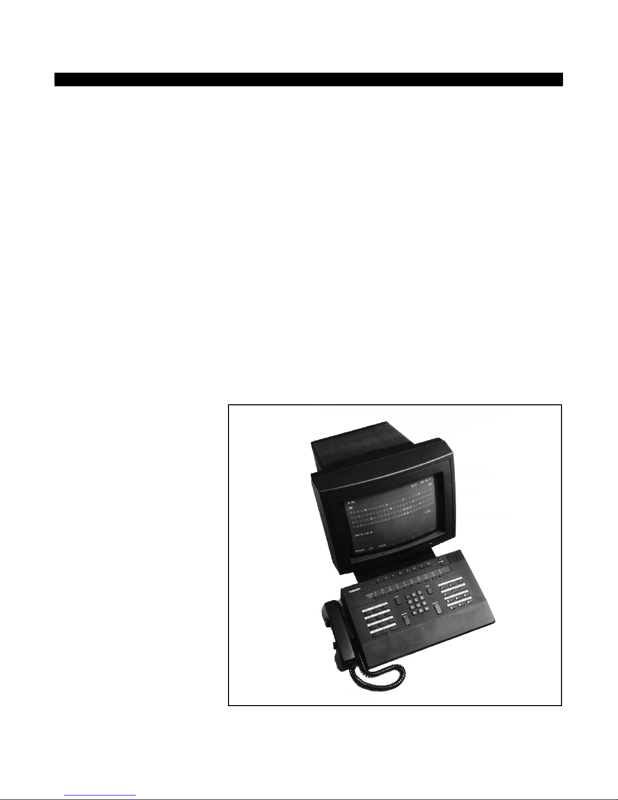
Attendant Console
STATION EQUIPMENT STRATA DK
The DK280 supports up to two Attendant Consoles on an RCTU-B
system, and up to four attendant consoles on a RCTU-C/D system.
Attendant Consoles are not supported on DK280 systems with RCTU-A,
or on DK8 or DK16 systems.
Attendant Consoles provide efficient high-volume incoming call handling.
The Strata DK280 Attendant Console provides color CRT or EL display of
call identification, calling/called numbers, intercom name indication, call
progress messages, BLF information, and soft key prompts. The Answer
button provides one-button answering for the attendant position. Incoming
Call Identification (ICI) keys provide specialized answering for all
categories of calls to the operator. The load sharing feature enables
multiple attendant consoles (up to 4) to receive incoming calls on a
rotation basis.
A DK280 Attendant Console processes calls faster than a DSS Console
because of the following capabilities and operational characteristics that a
DSS Console does not provide:
■ The Answer key is used to automatically answer any ringing call
regardless of type (incoming CO, intercom, transferred, recall, etc. ).
Multiple ringing calls are automatically queued and answered by the
Answer key either on a first-in first-out (FIFO) basis, or according to
the priority defined by the user with the Incoming Call Answer Priority
feature.
DESCRIPTION:
2-20 November 1993
Figure 2-7
Attendant Console
Page 40

Attendant Console
STRATA DK STATION EQUIPMENT
■ Incoming Call Answer Priority enables the Answer key to queue and
answer multiple ringing calls to the console in priority sequence. The
program default priority sequence is 1-Transfer Recall, 2-Hold Recall,
3-Transferred Call, 4-Incoming CO Line Call, 5-“O” Operator Call, 6Intercom Call. The priority sequence is programmable.
■ Emergency Calls always receive the highest Answer key priority at the
Attendant Console. They have priority over the FIFO or priority
sequence established in programming. Emergency calls are initiated
by station users by dialing a special number.
■ Incoming Call Identification (ICI) keys provide selective answering of
all categories of calls to the operator (intercom, transferred, hold
recall, transfer recall, emergency, operator, and incoming CO for all 16
CO line groups). Pressing the ringing ICI key, instead of using the
Answer key, enables the operator to specifically answer a certain type
of call and override the FIFO or priority order established by the
Answer key.
■ 10 Loop keys with two-color LEDs that show CO line status (ring, talk,
hold, etc.) and provides a place to hold calls waiting for assistance.
■ 8 Soft keys to provide feature prompting operation of a variety of
features.
■ Call progress messages display information about CO line status,
features activated, and station status much the same as the LCD on a
DKT.
■ BLF displays status of 100 stations’ status at a time (one DSS 60 total,
two DSSs 120 total), with the ability to display all stations’ status by
hundreds group. The BLF displays station numbers rather than port
numbers.
■ Overflow mode (via the Overflow button) causes attendant console
calls to be re-routed if they have been in queue longer than the time
period set by the Overflow Timer. Overflow calls go to the destination
assigned in programming, either a station or another attendant
console.
■ Load Sharing distributes incoming calls to multiple Attendant Consoles
(up to 4) on a rotational basis. This is better than ringing all calls to all
consoles. Individual operators only get their fair share of calls and
answer only those ringing at their console.
■ Color CRT display of console text information (station number, user
name, date, time), BLF status, call progress information (CO line
status, features activated, station status), and soft key prompting
labels, all at the same time.
November 1993 2-21
Page 41

Attendant Console
STATION EQUIPMENT STRATA DK
In DK280 answer position applications, you can offer flexibility by providing
a choice that meets the specific customer requirement. Choose between
Add-on Modules, DSS Consoles, or Attendant Consoles to best serve their
needs. Complimented by Auto Attendant and Voice Mail, you can offer the
most complete solution available today.
Sell an Attendant Console rather than a DSS Console when:
■ Very high incoming call traffic.
■ Too may stations to appear on a DSS Console and still make it
practical to use.
■ Multiple operators simultaneously share the call answering function.
■ Many calls of different types (incoming, transfers, recalls, etc.) are
received by the operator.
■ Features are required which the DSS Console does not provide (load
sharing, answer priority, emergency calls, overflow, etc.).
Sell a DSS Console rather than an Attendant Console when:
■ Incoming call traffic more moderate.
■ Operator needs individual button access to all CO Lines.
■ Simple BLF display and DSS transfer is a main application.
Sell an Add-on Module rather than a DSS Console when:
■ 20 or 40 DSS/BLF buttons are sufficient.
■ Smaller departmental answer positions.
■ A DKT needs more buttons for general feature use.
■ Don’t want to use additional station ports (Add-on Modules share the
station port of the attached DKT).
APPLICATIONS
2-22 November 1993
Page 42

Station Equipment
STRATA DK STATION EQUIPMENT
November 1993 2-23
Page 43

Station Equipment
STATION EQUIPMENT STRATA DK
2-24 November 1993
Page 44

Page 45

System Features
Page 46

STRATA SYSTEM FEATURES
FEATURES PAGE
1A2 Key System Interface................................................................................................................. 3-1
Account Codes
..................................................................................................................................3-2
Alarm Sensor ...................................................................................................................................
3-
4
Alternate Point Answer......................................................................................................................3-5
Amplified Conference........................................................................................................................ 3-6
Automated Attendant......................................................................................................................... 3-7
Automatic Hold/Automatic Release (Hold/Split)................................................................................ 3-8
Automatic Hold Recall....................................................................................................................... 3-9
Automatic Release from Hold............................................................................................................ 3-10
Automatic Station Relocation............................................................................................................ 3-11
Auxiliary Device Interface.................................................................................................................. 3-13
Background Music with Station Control............................................................................................. 3-14
Busy Station Ringing......................................................................................................................... 3-15
Centrex/PBX Compatibility................................................................................................................ 3-16
Centrex Ringing Repeat.................................................................................................................... 3-17
CO Line Call Pickup Groups ............................................................................................................. 3-18
CO Line Groups ................................................................................................................................ 3-19
CO Line Queuing .............................................................................................................................. 3-20
Conferencing..................................................................................................................................... 3-21
Credit Card Calling ("0 +" Dialing)..................................................................................................... 3-23
Data Switching .................................................................................................................................. 3-24
Delayed Ringing................................................................................................................................ 3-25
Direct Inward System Access (DISA)................................................................................................ 3-26
Distinctive CO Line/Intercom Ringing................................................................................................ 3-27
Door Lock Control ............................................................................................................................. 3-28
Door Phones ..................................................................................................................................... 3-29
DSS Console..................................................................................................................................... 3-30
DTMF and Dial Pulse CO Line Compatible....................................................................................... 3-31
DTMF Signal Time Continuous......................................................................................................... 3-32
DTMF Signal Time Setting................................................................................................................ 3-33
Dual FCC Registration ...................................................................................................................... 3-34
External Amplified Speaker............................................................................................................... 3-35
Flexible Button Assignment............................................................................................................... 3-36
Flexible Intercom Numbering ............................................................................................................ 3-38
Flexible Line Ringing Assignment..................................................................................................... 3-39
Flexible Slot Assignment................................................................................................................... 3-40
Least Cost Routing............................................................................................................................ 3-41
Live System Programming................................................................................................................ 3-42
Memory Protection............................................................................................................................ 3-43
Message Waiting............................................................................................................................... 3-44
Multiple Simultaneous Handsfree Intercom Paths ............................................................................ 3-45
Music-on-Hold Interface.................................................................................................................... 3-46
Music-on-Hold Source....................................................................................................................... 3-47
Night Ringing Answer Code.............................................................................................................. 3-48
Night Ringing over External Page..................................................................................................... 3-49
Night Ringing over Selected Page Zones.......................................................................................... 3-50
Night Transfer (Day/Night Modes)..................................................................................................... 3-51
Non-blocking Dialing ......................................................................................................................... 3-52
Page 47

SYSTEM FEATURES STRATA
FEATURES PAGE
Paging—All Call Voice Page ............................................................................................................. 3-56
Paging—External Page Interface...................................................................................................... 3-57
Paging—External Zone Paging......................................................................................................... 3-58
Paging—Group Paging...................................................................................................................... 3-59
Pooled CO Lines............................................................................................................................... 3-60
Power Failure Transfer....................................................................................................................... 3-61
Privacy/Non-privacy Option............................................................................................................... 3-62
Relay Service for External Page or Door Lock.................................................................................. 3-63
Relay Service for Night/Hold............................................................................................................. 3-64
Remote Administration/Maintenance ................................................................................................ 3-65
Station Hunting.................................................................................................................................. 3-66
Station Message Detail Recording (SMDR)...................................................................................... 3-67
System Battery Backup Interface...................................................................................................... 3-69
System Programming Through Station............................................................................................. 3-70
System Speed Dial............................................................................................................................ 3-71
Tandem CO Line Connection (Trunk-to-Trunk).................................................................................. 3-73
Tenant Service .................................................................................................................................. 3-74
TIE Lines........................................................................................................................................... 3-75
Toll Restriction................................................................................................................................... 3-76
Toll Restriction Override Codes......................................................................................................... 3-78
Toll Restriction Override by System Speed Dial................................................................................ 3-79
Transfer Privacy................................................................................................................................. 3-80
Traveling Class of Service................................................................................................................. 3-81
Voice Mail Interface........................................................................................................................... 3-82
Voice or Tone Signaling..................................................................................................................... 3-83
Wall or Table Mounting...................................................................................................................... 3-84
FIGURE LIST
FIGURE SUBJECT PAGE
3-1 SMDR Output—Outgoing Call ................................................................................................ 3-67
3-2 SMDR Output—Incoming Call ................................................................................................ 3-68
Page 48

1A2 Key System Interface
STRATA SYSTEM FEATURES
Optional on Se. Not available on STRATA DK systems.
The 1A2 Key System Interface (HCNB) allows CO lines to appear both on
1A2 key telephones and on Electronic Key Telephones in the STRATA S
e
system. When a call is in process on a CO line that has been “bridged” in
this way, it can be monitored or held at both the 1A2 station and the EKT
station. The LED for that line on the EKT station and the lamp for that line
on the 1A2 telephone will both flash or light according to the status of the
line—in use, on hold, and so on.
With the 1A2 Key System Interface, the STRATA Sesystem will provide Alead control, lamp signal detection and dial outpulsing to an existing
mechanical key system, such as a 1A2 system. Each 1A2 Key System
Interface will allow up to three CO lines to be bridged.
1A2 Key System components can be used with a STRATA Sesystem. A
customer who is replacing a mechanical key system can keep part of a
1A2 system for use by employees who prefer to use the familiar system
and do not need the functionality of the STRATA Se. Keeping part of the
1A2 system might also save money for the customer.
SYSTEM AVAILABILITY
DESCRIPTION
BENEFITS
3-1
Page 49

STATION FEATURES STRATA
FEATURES PAGE
Private CO Lines............................................................................................................................... 4-54
Push-button Dialing........................................................................................................................... 4-55
Release Button.................................................................................................................................. 4-56
Remote Retrieval of Held Calls......................................................................................................... 4-57
Repeat Last Number Dialed.............................................................................................................. 4-58
Ringing Line Preference.................................................................................................................... 4-59
Saved Number Redial....................................................................................................................... 4-60
Speed Dial Buttons ........................................................................................................................... 4-61
Station Speed Dial ............................................................................................................................ 4-62
Timed Reminder................................................................................................................................ 4-63
Toll Restriction Override Code Revision............................................................................................ 4-64
User Programmable Feature Buttons................................................................................................ 4-65
Page 50

Account Codes
SYSTEM FEATURES STRATA
Forced and Voluntary Account Codes is a standard feature, programmable
by station and/or CO line on all STRATA systems. On the Se, the feature is
not available on off-premises stations or stations supported by an HIOB.
On DK systems, the feature is available on off-premises stations.
Verifiable (forced or voluntary) Account Codes is a standard feature on
DK16 and DK24/56/96 Release 4 systems not available on STRATA Se.
A user can enter an account code from 4 to 15 digits in length from a
station telephone dialpad for any call. The account code will be printed on
the SMDR printout with other call details so that the customer can identify
all calls associated with a specific account code. Account codes are often
used for cost allocation.
Account codes can be required (forced) on a CO line-by-CO line basis.
Stations can also be forced to enter an account code before dialing a call.
For stations that have the Forced Account Code feature, users must enter
an account code whenever they use CO lines that require account codes.
Stations that do not have the Forced Account Code feature do not have to
enter codes, regardless of the status of the CO line in use. Stations can
voluntarily enter account codes on any incoming or outgoing call over any
CO line. While account codes can also be entered on incoming calls, the
entry cannot be forced on these calls.
DK24/56/96 Release 4 systems can also have up to 300 verifiable account
codes, which can be forced and/or voluntary. Therefore, stations and CO
lines on these systems can have one of four possible account code
features:
■ Forced account codes.
■ Voluntary account codes.
■ Forced verifiable account codes.
■ Voluntary verifiable account codes.
If verifiable account codes are forced, the DK system must verify the code
entered by the user before it will allow the call.
Verifiable account codes can be set up in two ways:
■ All digits in the code can be verified. With this method, 300 specific
account codes can be verified. For example, if a 4-digit code is used,
the system can verify 300 specific 4-digit numbers. If a 9-digit code is
used, the system can verify 300 specific 9-digit numbers.
■ The first “por tion” of the code can be verified. This allows 300 specific
verifiable “prefixes,” which can then allow thousands of “partially”
verifiable account codes. For example, with a 5-digit code, there could
be 300 verifiable 3-digit prefixes:
SYSTEM AVAILABILITY
DESCRIPTION
3-2
Page 51

Account Codes
STRATA SYSTEM FEATURES
100 _ _, which verifies 10000, 10001,
10002, ... 10099 (100 codes)
101 _ _, which verifies 10100, 10101, 10102, ... 10199 (100 codes)
102 _ _, which verifies 10200, 10201, 10202, ... 10299 (100 codes)
.
.
.
299 _ _, which verifies 29900, 29901, 29902, ... 29999 (100 codes)
Each of the 300 verifiable prefixes partially verifies 100 codes, for a total of
30,000 partially verifiable codes.
A verifiable account code can have a toll restriction class of service. When
an account code is entered at a station, the system will check the toll
restriction class of service associated with that account code, and will then
determine if the call is allowed.
On DK16 and DK24/56/96 Release 4 systems, an Account Code button
can be programmed on an electronic or digital key telephone to facilitate
voluntary account code entry.
Account codes help a business control costs and ensure accurate billing to
departments, clients, projects, or individual employees.
BENEFITS
3-3
Page 52

Alarm Sensor
SYSTEM FEATURES STRATA
Optional on all STRATA systems.
The alarm sensor is configured with a customer-supplied alarm. When the
sensor detects that the alarm relay is activated, it causes all electronic key
telephones to sound a startling tone. Any station programmed with an
Alarm (ALRM) button can reset the alarm on a DK system. With S
e
systems, only Station 10 can be programmed with an Alarm button.
The PIOU or PIOUS option interface unit must be installed on a DK
system to provide the Alarm Sensor feature. On Sesystems, the HDCB
Door Phone Control Box is required.
The customer has the convenience of being able to control an alarm from
electronic key telephone sets.
SYSTEM AVAILABILITY
DESCRIPTION
BENEFITS
3-4
Page 53

Alternate Point Answer
STRATA SYSTEM FEATURES
Standard on all STRATA systems.
Alternate Point Answer allows certain station(s) in the system to answer a
CO line call that has been transferred to another station. The line on which
the call has been transferred must appear on the station using Alternate
Point Answer.
For business situations in which employees have high mobility, Alternate
Point Answer promotes efficiency in call handling and better service to
callers. It can also minimize the distraction caused by unanswered ringing
phones.
SYSTEM AVAILABILITY
DESCRIPTION
BENEFITS
3-5
Page 54

Amplified Conference
SYSTEM FEATURES STRATA
Amplified conference is available on STRATA Se, DK16, and all
DK24/56/96 Release 4 systems, using a customer-supplied automatic gain
switched, 2-way line amplifier. One amplifier can be connected on the Se.
Up to two amplifiers can be connected on the DK16, and up to four
amplifiers can be connected on DK24/56/96 Release 4 systems.
One or more customer-provided amplifiers can be connected to
proprietary station por ts in the system. The amplifier(s) will automatically
be activated whenever a user conferences two CO lines together.
On the Se, the amplifier will compensate for loss in volume through the
public telephone and system network.
With DK systems, there is negligible loss through the system, and the
amplifier compensates for loss in volume over the public network.
Any two-way line amplifier that is FCC-registered with Automatic Gain
Control (AGC) should be compatible. Model VFR 5050 has been
successfully used.
The amplifier will amplify the signal between any two outside CO lines as
well as between the second CO line selected. If Tandem or DISA CO line
connections are allowed in the system, the CO line-to-CO line connection
will be amplified.
Amplified connections are available on a first-come first-served basis. On
the Se, amplified conference is not available to a standard telephone or to
any station or device supported by an HOXB or HIOB. On DK systems,
amplified conference is available to a standard telephone.
Each amplifier requires two EKT station ports, and reduces the station
capacity by two. On DK systems, the two ports supporting the amplifier
must be designated ports on a PDKU or PEKU card. One PDKU/PEKU
will support one external amplifier.
External parties on a conference call will be able to hear each other with
increased loudness. Conference calls will be shorter and more efficient,
since time will not be wasted repeating inaudible parts of the conversation.
Shorter calls are cheaper calls. When conferees can hear clearly, they will
get accurate information.
SYSTEM AVAILABILITY
DESCRIPTION
BENEFITS
3-6
Page 55

Automated Attendant
STRATA SYSTEM FEATURES
Standard on Strata DK16 and DK24/56/96 Release 4 systems.
Auto Attendant operates like a round-the-clock operator that quickly and
efficiently directs incoming CO line calls to their proper destinations. CO
lines programmed with Auto Attendant are answered by a digital
announcer that greets callers and then provides them with a menu of
dialing options.
Callers who are directed to a busy or unanswered destination can either
be routed to a secondary announcement, which informs the callers that
the destination is unavailable and repeats the menu, or can be routed back
to the initial, primary announcement. If the call is routed back to an
unavailable digital announcer, the call will then simultaneously ring an
overflow station and camp on to the destination station (if it was busy). If
unanswered, the re-routed call will just ring the overflow station.
In addition to quickly and efficiently directing calls, the Auto Attendant
assures that calls are answered even when lines are busy. When the Auto
Attendant is busy, incoming callers will receive ring back tone and queue
onto the Auto Attendant. When the Auto Attendant becomes available, all
of the calls in queue will be switched to the Auto Attendant simultaneously
and receive the same greeting.
Customers can have up to four Auto Attendants. One Auto Attendant can
accommodate light to normal incoming call traffic, while up to four can
satisfy the demands of heavy traffic applications. Each Auto Attendant can
have either a primary announcement only, or both a primary and
secondary announcement, for a system maximum of eight
announcements. Each announcement is stored on a customer-supplied
digital announcer.
The Auto Attendant feature is extremely flexible. The dialing menu can
have as many as 10 options, which can direct calls to specific stations,
hunt groups, and ACD groups. CO lines that are assigned as Auto
Attendant lines in any of the three system modes (day, day 1, night) can
be assigned to ring stations or night bell when the system is switched to
another mode.
Installing Auto Attendant is easy. The customer only needs to provide the
digital announcer(s), which easily connect to standard telephone ports.
With Auto Attendant, live operator(s) are not needed to answer and route
incoming calls. This frees employees to perform other tasks.
24-hour coverage means no need to worry about lunch and break
coverage, and provides after hours coverage. Also, overflow call coverage
during peak traffic periods is handled automatically.
Auto Attendant can process a larger volume of calls, more quickly and
efficiently, than a live operator. This provides incoming callers better
overall service.
SYSTEM AVAILABILITY
DESCRIPTION
BENEFITS
3-7
Page 56

Automatic Hold/Auto Release (Hold Split)
SYSTEM FEATURES STRATA
Standard on Strata DK16 and DK24/56/96 Release 4 systems.
The system can be set in system wide programming for either Auto Hold
or Auto Release of an existing call when another incoming call is
answered.
Auto Hold automatically places an existing call on hold when another
incoming call is answered.
Auto Release automatically releases an existing call when another
incoming call is answered.
Both Auto Hold and Auto Release can be overridden by pressing the
Release or Hold button, respectively, before answering another incoming
call.
The customer can choose whichever is most efficient for their business.
Auto Hold saves time in call splitting applications in which users want to
switch back and forth between two calls. Auto Release saves time in
heavy call answering applications in which users want to disconnect from
a call they are finishing with and answer the next call simultaneously.
SYSTEM AVAILABILITY
DESCRIPTION
BENEFITS
3-8
Page 57

Automatic Hold Recall
STRATA SYSTEM FEATURES
Standard on all STRATA systems.
When a station user puts a call on hold, the call will automatically ring
back to that station after a programmable period of time. Hold recall time is
normally set at 32 seconds, but can be programmed from 16 to 160
seconds.
As a programmable option, hold recall can be disabled altogether or can
be programmed for different recall times on a station-by-station basis,
according to the specific need of that station user.
Automatic Hold Recall insures that station users will be reminded to pick
up a call that has been put on hold. Courteous customer ser vice dictates
that the caller should be acknowledged periodically and informed about
the cause of any delay. This feature can help a company project a
professional, efficient, and courteous image.
SYSTEM AVAILABILITY
DESCRIPTION
BENEFITS
3-9
Page 58

Automatic Release from Hold
SYSTEM FEATURES STRATA
Standard on all STRATA systems.
The STRATA system will automatically release a held CO line if a
disconnect signal is received from the central office. This feature can be
enabled on a CO line-by-CO line basis.
The customer will have full use of all CO lines at all times. A CO line will
not be tied up if a station user puts it on hold and the caller hangs up
before the station user returns to the call.
SYSTEM AVAILABILITY
DESCRIPTION
BENEFITS
3-10
Page 59

Automatic Station Relocation
STRATA SYSTEM FEATURES
Standard on Strata DK16 systems.
When Automatic Station Relocation is activated, a telephone can
automatically maintain its particular characteristics (station number,
personal speed dial, feature set, etc.) when it is relocated from one
jack/port to another jack/port. A vacant jack/port that is not programmed
with any characteristics must be available whenever relocating a station.
Only one telephone can be relocated at a time. Automatic Station
Relocation is available system wide and can be turned off and on by a
station assigned in system programming.
Automatic Station Relocation makes moving telephones quick and easy.
Just unplug the phone from one jack/port and plug it into another. It also
saves the expense of having a third party reprogram the system to reflect
these changes.
With most systems, whenever someone moves to a different office or
location, the system administrator or third party installation support
personnel must change system programming to reassign the telephone
stations affected. This is time consuming if this activity takes place with
any degree of frequency. It can also be expensive if the customer must call
third party support personnel to have the station reassignment made.
SYSTEM AVAILABILITY
DESCRIPTION
BENEFITS
3-11
Page 60

Auxiliary Device Interface
SYSTEM FEATURES STRATA
STRATA Secan have up to four Auxiliary Device Interfaces (HIOBs),
allowing the system to be connected to up to four auxiliary devices.
The HIOB is not available and not necessary for DK systems. Two-wire
auxiliary devices are supported by the Standard Telephone Interface Unit
(KSTU or PSTU), or the Standard/Electronic Telephone Interface Unit
(PESU). For details, see “Voice Mail Interface” in the System Features
section of this manual.
The Auxiliary Device Interface (HIOB external module) provides an
interface between the STRATA Seand an external device such as a voice
mail port, a standard DTMF or rotary telephone, a modem, or an
answering/dictation machine. The interface allows the system to interact
with these devices.
The HIOB unit contains a DTMF generator and a DTMF receiver for use
with auxiliary devices. It also contains its own ring generator. Each HIOB
requires one station port.
The maximum distance between the Key Service Unit (KSU) and the
HIOB is 650 feet when 24 AWG wire is used. The loop limit between the
HIOB and the device is 300 ohms.
When the Auxiliary Device Interface is used with a voice mail system, it
can allow the following features, depending on the specific brand of voice
mail system.
If the CO line rings direct to the HIOB, the station assigned to the HIOB
can be programmed to send 16 digits to the voice mail system when it
answers. This would be useful if a customer wanted to have a caller
connect directly to an audiotext message by dialing a certain telephone
number.
Allows a station user to forward calls to voice mail box so that the caller
can leave a voice message. DTMF tones are automatically sent to the
voice mail device to direct the call to the called party’s mailbox.
Allows a station user to retrieve messages from his/her mailbox by
pressing the INT button, followed by the MW/FL button. DTMF tones are
automatically sent to the voice mail device which accesses the station
user’s mailbox.
If the voice mail system is assigned as the STRATA message center, it can
activate a message waiting LED on a station when the mailbox
corresponding to the station has received a voice message.
DTMF signaling is required to activate and control functions on voice mail
systems. However, the dialpad on an electronic key telephone generates
electronic, not DTMF tones. Since the Auxiliary Device Interface has a
DTMF tone generator, it enables the station user to control the voice mail
equipment with the dialpad on the EKT. The Auxiliary Device Interface will
translate the electronic tones to DTMF tones.
SYSTEM AVAILABILITY
DESCRIPTION
CO LINE ASSIGNED TO RING
HIOB
CALL FORWARD TO VOICE MAIL
BOX
MESSAGE RETRIEVAL
MESSAGE WAITING INDICATION
VOICE MAIL CONTROL
3-12
Page 61

Auxiliary Device Interface
STRATA SYSTEM FEATURES
The Auxiliary Device Interface insures that a business will be able to easily
connect certain peripheral devices to their system at a reasonable cost,
enabling them to gain the cost and productivity benefits offered by such
equipment.
BENEFITS
3-13
Page 62

Background Music with Station Control
SYSTEM FEATURES STRATA
Optional on all STRATA systems.
If a system is connected to a music source and this feature is activated, a
station user can access background music through the speaker of an
Electronic Key Telephone. The music can be turned on and off at the
user’s option via the Speaker button on the Se, and the BGM button or dial
access code on a DK system. The user can control the volume.
If an external paging system is installed, music can also be broadcast
through the external paging speakers, providing background music
throughout the facility.
The background music source is customer-supplied. For STRATA Se, the
background music source for EKTs and for external page is the same as
the source for music-on-hold.
For DK systems, up to three separate music sources can be connected to
the system at the same time. One source can broadcast background
music over EKT speakers, while a second broadcasts over external
speakers and a third provides music or a recording for music-on-hold.
When background music is broadcast over electronic key telephone (EKT)
speakers, no optional hardware is required. The STRATA DK music source
for both background music on EKT speakers and music-on-hold connects
directly to the common control unit (KMAU, PCTU, or PCTUS). The music
source for background music over EKT speakers can connect to a
designated station port on a KCDU, PDKU, PEKU, or PESU, to allow
separate sources for music-on-hold and EKT background music.
When music is broadcast unamplified over external speakers on a DK
system, the Option Interface Unit (PIOU, PIOUS or PEPU) must be
installed. Amplified output requires either the PIOU or PEPU.
On DK systems, the station assigned to port 00 can switch the background
music over external page on and off by dialing a code.
Music on both the external speaker and the telephones will be muted
when a paging announcement is made or when night ringing occurs.
Some employees find it relaxing to listen to music as they are working.
This feature enables the employer to provide music that is conducive to
the work environment. The employer can allow employees to listen to
music, without the conflict that can accompany the use of radios or tape
recorders.
SYSTEM AVAILABILITY
DESCRIPTION
BENEFITS
3-14
Page 63

Busy Station Ringing
STRATA SYSTEM FEATURES
Standard feature, programmable by station, on Strata DK16 and
DK24/56/96 Release 4 systems.
Electronic and digital telephones programmed with this feature will ring
even when they are busy on another call. This is important to voice mail
and auto attendant applications, in which incoming calls are often
transferred from the auto attendant to busy stations.
When either an internal caller places an intercom call, or transfers an
external call to a busy telephone assigned with this feature, they hear ring
back tone, not busy tone. The called, busy telephone will ring with a muted
tone, and its applicable CO line or INT LED will flash continuously at a fast
rate. To answer the incoming call, the called party can either transfer,
release, or place the current call on hold before pressing the button
associated with the flashing LED. Otherwise, the transferred call will campon after ringing and not being answered. Called stations can continue to
operate other features in the normal way. If called while idle, these stations
will ring as normal.
Any number of electronic and digital telephones can be programmed with
this feature. Busy Station Ringing does not operate on standard
telephones.
Busy Station Ringing helps insure that important calls are answered more
efficiently. This feature is especially useful for answer position telephones
that must be available to answer calls. This prevents calls transferred from
the auto attendant to a busy station, from being transferred back to the
auto attendant. Callers are not frustrated by looping back and forth without
talking to anyone.
SYSTEM AVAILABILITY
DESCRIPTION
BENEFITS
3-15
Page 64

Centrex/PBX Compatibility
SYSTEM FEATURES STRATA
Standard on all STRATA systems.
Any STRATA Seor DK system can be installed behind a Centrex or PBX
system. It can function as part of the Centrex or PBX system while
providing its users with the STRATA Seor DK features and electronic
feature telephones.
To further enhance STRATA Seand DK compatibility with Centrex and
PBX, access codes for features in the host system can be programmed as
if they were system speed dial numbers. These codes can then be
assigned to Speed Dial buttons or SD buttons (also known as Station
Automatic Dialing buttons or ADL buttons), providing one-button access to
the CO, Centrex or PBX feature.
Each CO/Centrex/PBX feature access code to be programmed can have
up to 16 digits, including pauses and flashes. Like system speed numbers,
these codes can only be programmed or changed by Station 10 on S
e
systems, and by the station assigned to port 00 (usually 200) on DK
systems.
When a STRATA Seor DK system is installed behind a PBX, some or all
of the CO/PBX line buttons function like PBX extensions. When such a
PBX line button is accessed, the station user will get dial tone—but it is
PBX dial tone, not CO dial tone. If the user wants to access a CO line on
the PBX, he or she must then dial an access code. For example, “9” might
be dialed to get a local CO line; TIE lines to other company locations might
be accessed by “72” or “73”.
A STRATA Seor STRATA DK system can be instructed, through
programming to recognize these PBX access codes, and disregard them
on identified lines when it inspects dialed numbers for toll restriction
purposes, or performs other features such as Last Number Redial. This
allows the system to continue to provide its features, even when calls are
ultimately going out from the PBX.
Centrex and PBX compatibility can result in cost savings to the customer.
The economical STRATA Seand DK systems can be used in satellite
locations; yet users can take advantage of the Centrex and/or PBX
features, the PBX trunking, and the PBX networking capabilities.
STRATA Seand DK systems can also be used within a PBX environment
to serve a community of interest which needs the functionality of electronic
key telephone sets that may not be provided by the PBX. Also,
CO/Centrex/PBX Feature buttons give users easy, one-button access to
features that would otherwise require more complicated access
procedures. Since users do not have to look up feature access codes, they
will save time. Dialing errors which waste time can also be eliminated
through the use of feature buttons.
SYSTEM AVAILABILITY
DESCRIPTION
BENEFITS
3-16
Page 65

Centrex Ringing Repeat
STRATA SYSTEM FEATURES
Standard on all STRATA systems.
STRATA Seand DK systems can be programmed to emulate Centrex or
PBX ringing patterns, allowing the user to differentiate between station or
CO line calls, and various callback features on the Centrex or PBX line.
Centrex Ringing Repeat allows the user to hear the same on/off ringing
patterns that are heard for special calling and callback features on CO,
Centrex or PBX lines. Users do not have to learn new ringing cadences,
and can easily differentiate between station or CO line calls, or various
callback features on the Centrex or PBX line.
SYSTEM AVAILABILITY
DESCRIPTION
BENEFITS
3-17
Page 66

CO Line Call Pickup Groups
SYSTEM FEATURES STRATA
Standard on all STRATA systems.
With the CO Line Call Pickup Group feature, up to two CO Line Call
Pickup Groups can be programmed. Ringing CO lines in the first CO line
group can be picked up with an access code or with the “CPU1” button
(“PKUP1” button on DK systems), if it appears on the telephone. Ringing
CO lines in the second CO line group can be picked up with an access
code or with the “CPU2” button (“PKUP2” button on DK systems), if it
appears on the telephone.
As an option, all CO lines could be put into one group. A ringing CO line
could then be picked up with an access code or with the “CPU” button
(“PKUP” button on DK systems).
On DK systems with tenant service, the CO lines for tenant 1 could be put
into one CO line group, and the CO lines for tenant 2 could be put into
another CO line group. Then, tenant 1 station users can use the “CPU1”
(or “PKUP1”) button and tenant 2 station users can use the “CPU2” (or
“PKUP2”) button to pick up the CO lines assigned to them.
Call handling for CO line calls can be more convenient and efficient with
this feature. Station users do not have to determine which CO line is
ringing in order to answer it, nor does the ringing CO line have to appear
on their telephone in order for them to pick it up.
SYSTEM AVAILABILITY
DESCRIPTION
BENEFITS
3-18
Page 67

CO Line Groups
STRATA SYSTEM FEATURES
Standard on all STRATA systems.
Also known as Tr unk Groups, this feature allows the CO lines on any
STRATA system to be assigned to CO line groups. Station users can
access the CO line groups by dialing a specific CO line group access
code. This allows a customer to group various types of CO lines together
for convenient access.
For example, a customer might want to put TIE lines in one CO line group
and WATS lines in another. Users would then access the CO line group
that was appropriate for the type of call being placed. If all lines in that CO
line group were busy, the user could queue for the CO line group.
If the system is programmed for Least Cost Routing, station users will not
need to select a specific CO line group. STRATA Sesystems will
recognize up to four CO Line groups. STRATA DK systems can be
programmed for up to eight CO line groups.
On DK systems, CO line groups correspond to the pooled line groups that
can be assigned to buttons on an EKT. Pooled Line Group 1 is CO Line
Group 1, Pooled Line Group 2 is CO Line Group 2, and so on. Up to four
Pooled Line Group buttons for the same CO line group can be assigned to
a station to facilitate handling several calls on that CO line group at that
station. See “Pooled CO Lines” later in this section.
CO Line Groups are required for other features on the system. They
enable queuing, single line telephone access to CO lines, Pooled Line
Buttons, CO Line Call Pickup Groups, and Tenant Service. They are also
used to define Least Cost Routing schemes.
SYSTEM AVAILABILITY
DESCRIPTION
BENEFITS
3-19
Page 68

CO Line Queuing
SYSTEM FEATURES STRATA
Standard on all STRATA systems.
This feature is also known as Trunk Queuing. When all lines are in use,
this provides a means for station users to be stacked in a waiting queue for
an available outgoing CO line. The Automatic Callback feature notifies the
station user when a line becomes available.
With STRATA DK, an EKT or a standard single line station can queue up
for a busy outgoing CO line or CO line group. When the desired line is
available, the system calls the station back, and the station can proceed
with the call.
With STRATA Se, as a programmable option, the system may be equipped
to queue up for a line within one trunk group (dial 9) or eight trunk groups
(dial 91-98).
Users save time since they do not have to keep checking to see if the line
they want is free. Once they have queued for the line, they can return to
their work, knowing that the system will call them as soon as the line is
available.
If LCR is installed, CO Line Queuing provides a convenience to users who
are restricted to certain call routes.
SYSTEM AVAILABILITY
DESCRIPTION
BENEFITS
3-20
Page 69

Conferencing
STRATA SYSTEM FEATURES
On STRATA Sesystems, non-amplified conference is standard, with
amplified conference available as an option. Conferencing with two CO
lines can not be originated by any type of single line EKT, or any station or
device that is supported by an HOXB, HIOB, or PSTU. An EKT which sets
up a conference using two CO lines must have two CO line buttons.
On DK systems, non-amplified conference is also standard, with amplified
conference available as an option on DK16 and DK24/56/96 Release 4
systems. Any electronic or standard telephone can set up conferencing
with other electronic or standard telephones.
On DK systems, CO buttons are not required for conferencing. The
Conferencing feature is available on pooled line buttons, but the originating
telephone must remain connected until the call is complete.
The system can connect the following conference combinations:
STRATA S
e
ICMs CO Lines Stations
1 up to 4
1 up to 4
2 up to 3
DK Systems
ICMs CO Lines Stations
1 up to 3
1 up to 4
2 up to 2
The Conferencing feature can be enabled or disabled system-wide in
programming.
On DK24/56/96 systems equipped with a PCTU common control, 32
conference channels are available. Four parties can participate in each
conference, and as many as eight conferences can be held
simultaneously. A DK16 system, or a DK24 equipped with a PCTUS, has
14 conference channels. Four parties can par ticipate in each conference,
and as many as three conferences can be held simultaneously.
On the STRATA Se, one conference channel is available. Up to five parties
can participate in a conference.
On Se, DK16, and DK24/56/96 Release 4 systems, the conference can be
optionally amplified with a customer-supplied 2-way amplifier. On the Se,
this amplifier will compensate for loss in volume through both the system
and the public telephone network. On DK systems, there is negligible loss
through the system, so the amplifier compensates for loss in volume over
the public network. (See “Amplified Conference” for details.)
SYSTEM AVAILABILITY
3-21
Page 70

Conferencing
SYSTEM FEATURES STRATA
Sometimes in business it is convenient, efficient, and productive to
conference two CO lines. Everyone participating in the conference gets
the same information at the same time, reducing confusion and saving
time.
BENEFITS
3-22
Page 71

Credit Card Calling ("0+" Dialing)
STRATA SYSTEM FEATURES
Standard feature, programmable by station on DK16 and DK24/56/96
Release 4 systems.
Note that STRATA Se, and DK pre-Release 4 systems also allow “0+”
dialing, but Toll Restr iction must be programmed a certain way. This is not
as flexible and lacks some of the safeguards provided by STRATA DK16
and DL24/56/96 Release 4.
"950-X0XX" credit card calling is available on STRATA Seand DK
systems.
Callers can make “0+” telephone credit card calls from selected toll
restricted stations. Calls are billed to the credit card instead of the CO line.
The “0+” credit card calling feature can be selectively assigned to stations
and to CO lines.
If a toll restricted station has the credit card calling feature, the DK system
requires the user to enter a certain number (programmable) of digits after
dialing “0” on a CO line that has the feature. If the caller does not enter
that number of digits within 20 seconds after dialing “0”, the call will be
dropped.
If the system has Least Cost Routing, a station that has the feature can
place a “0+” credit card call on any CO line accessed by Least Cost
Routing.
Customers can provide the convenience of “0+” telephone credit card
calling without compromising toll restriction.
SYSTEM AVAILABILITY
DESCRIPTION
BENEFITS
3-23
Page 72

Data Switching
SYSTEM FEATURES STRATA
Optional feature on DK16 and Release 4 STRATA DK24/56/96 systems.
A DK16 or Release 4 DK24/56/96 system has sophisticated data switching
capabilities provided through data interface units (DIU). This allows
internal calls between data devices such as personal computers, printers,
terminals, and mainframe computers. It also allows external data calls over
the public telephone network with a modem. The system can be
programmed with 1-4 security groups, and can restrict calls between
groups. It can also support modem pooling and printer sharing.
Data switching can be done through digital key telephones with integrated
DIUs or stand-alone DIUs.
Simultaneous voice and data transmission over a single wire pair
eliminates additional wiring requirements and minimizes port usage on the
system.
Modem pooling and printer sharing enables multiple users to maximize
efficient usage of expensive peripheral devices.
PC keyboard dialing of data or voice calls increases user efficiency. An
example is auto dialing by name or initial from directories stored in PCs
equipped with inexpensive desk organizer-type software (modem not
required).
Security groups help control who is authorized to make outside data calls,
which can get expensive if linked to databases which charge for access.
SYSTEM AVAILABILITY
DESCRIPTION
BENEFITS
3-24
Page 73

Delayed Ringing
STRATA SYSTEM FEATURES
Standard on all STRATA systems.
A ringing delay of 12 or 24 seconds can be programmed for each CO line
that rings at a given station. For example, an incoming CO line can be
programmed to ring at one station (or a group of stations) immediately
when the call comes in, and at a second station (or group of stations) 12
or 24 seconds later.
Delayed Ringing can be applied to ringing assignments for DAY 1, DAY 2,
and NIGHT ringing modes. (See Night Transfer.)
Delayed Ringing improves call handling by allowing the customer to
provide one or more alternate answering positions for any incoming CO
line. Calls have a greater chance of being answered promptly.
Because of the delay in ringing, employees at alternate answering stations
will not be disturbed by ringing while they wait to see if the called station
will answer. If the line rings at their station, they know they should answer
it.
SYSTEM AVAILABILITY
DESCRIPTION
BENEFITS
3-25
Page 74

Direct Inward System Access (DISA)
SYSTEM FEATURES STRATA
Standard on STRATA DK systems. Not available on the STRATA Se.
By calling in on a specific telephone number assigned to Direct Inward
System Access (DISA), callers can reach the DK system and then dial
internal stations or outgoing CO lines directly, without going through the
attendant.
The caller dials the CO line number for DISA and hears two rings. Then a
tone sounds for nine seconds, during which the caller dials a station
number or the access code for a specific outgoing CO line or line group
(“9” for Least Cost Routing is not allowed). If the station or CO line is busy,
the caller can dial another station or CO line. If no station number or CO
line access code is dialed and the nine-second interval elapses, the call is
transferred to a pre-assigned ringing arrangement (DAY, DAY2, or NIGHT).
An optional DISA security code (1 - 15 digits) can be programmed. When
the security code is programmed, the caller must enter it in order to make
DISA calls on CO lines. The security code is not required to dial internal
stations.
DK systems can provide a DISA class of service to CO lines, which allows
Toll Restriction to be applied to DISA CO line calls. For example, DDD
lines could be restricted to local calls only when accessed through DISA.
Any number of CO lines can be programmed with the DISA feature. CO
lines can be programmed as normal lines during daytime operation and
DISA lines at night.
DISA can save money for a customer by allowing employees to use the
company’s calling network even when they are not in the office.
Employees working in the field will save time because they can call directly
into the station they want. They don’t have to wait for the attendant to
answer their calls and they won’t waste time holding for the attendant to
process their calls.
DISA can reduce the attendant’s incoming call load, and possibly save
money for the customer by eliminating the need for a second attendant.
When the attendant has fewer calls to handle, he or she can give better
service to the callers who need it.
Before and after hours, family members and others can use DISA to
directly dial an employee’s station, improving the chances that the
employee will receive the call.
SYSTEM AVAILABILITY
DESCRIPTION
BENEFITS
3-26
Page 75

Distinctive CO Line/Intercom Ringing
STRATA SYSTEM FEATURES
Standard on all STRATA systems with electronic or digital telephones. On
STRATA DK systems, this feature is optional for standard telephones.
Incoming CO lines ring with a different tone than do intercom calls. Users
can easily distinguish the type of call, even when the telephone is not in
view.
This feature is a convenience to the user since it identifies the type of call
ringing to the station. The station user can answer with an appropriate
greeting.
SYSTEM AVAILABILITY
DESCRIPTION
BENEFITS
3-27
Page 76

Door Lock Control
SYSTEM FEATURES STRATA
Optional on all STRATA systems. For details on Door Lock Control for
STRATA Se, see the feature “Door Phones.”
The Door Lock Control feature allows any telephone programmed with a
Door Lock button to unlock a door. Pressing the button activates the
electronic door lock and the lock opens for 3 or 6 seconds, as specified in
programming. The electronic door lock mechanism must be supplied by
the customer.
On the STRATA Se, Door Lock Control is a function of the HDCB external
module. Each HDCB can support one door lock. The Sesystem maximum
is four.
On STRATA DK systems, one Door Lock Control is supported by an
Option Interface Unit—either the PIOU, PIOUS, or PEPU. Up to four more
door locks can be installed, each requiring an HDCB or DDCB. On a DK24
system equipped with a PCTUS, a maximum of four door locks can be
installed. On a DK16, a maximum of 3 door locks is supported.
Telephone control of a door lock is a great convenience, since it eliminates
the need for extra equipment to remotely control the lock, or the need to
physically get up and go to the door to open it.
SYSTEM AVAILABILITY
DESCRIPTION
BENEFITS
3-28
Page 77

Door Phones
STRATA SYSTEM FEATURES
Optional on all STRATA systems. Up to 6 door phones can be installed on
the Seand DK16. On the DK24, up to 9 door phones can be installed if
the system is equipped with a PCTUS, and up to 12 can be installed if the
system is equipped with a PCTU. Up to 12 door phones can be installed
on the DK56 and DK96.
The optional door phone/monitor station is an external/remote two-way
speaker box which has a direct voice link to a station. Pressing the button
on a door phone sends a distinctive ringing to the stations which have
been programmed to receive ringing from that door phone. When a station
answers, it is automatically connected to the door phone. Door phones can
be programmed to ring over external page when the system is in night
mode.
A station can dial an individual door phone/monitor station and either
converse with someone at the door phone, or simply monitor conversation
or sound at the door phone. No warning tone will be heard at the door
phone/monitor station when it is called by a station.
Door phones are supported by the door phone control box (HDCB or
DDCB) external module. One control box supports up to three door
phones. On the STRATA Se, each HDCB requires one circuit on a station
card (SSTU). On DK systems, the HDCB requires one EKT station circuit
on a PEKU or PESU, or the DDCB requires one DKT station circuit on a
PDKU or KCDU.
On the Se, if the door phone option is installed in a system, the Alarm
feature or the Lock feature can optionally be activated. The Alarm feature
enables a signal to be sounded at all stations whenever a contact closure
is received from an external alarm system. The alarm can be turned off by
Station 10 only. The Alarm feature is supported by the HDCB module. See
the “Alarm Sensor” feature for details about the alarm on DK systems.
The Lock feature enables selected stations to control a door lock or other
device by pressing a “DRLK” button on the telephone. The door lock
control can be programmed to operate for 3 seconds or for 6 seconds. On
the STRATA Se, each HDCB module can support one door lock. Thus, if
the customer wanted to have door lock control on both the front and the
back doors of the building, two HDCBs would be required.
On DK systems, one door lock control can be supported by an Option
Interface Unit (PIOU, PIOUS, or PEPU). Up to four more door locks can be
installed, each requiring an HDCB or DDCB. On a DK24 system equipped
with a PCTUS, a maximum of four door locks can be installed. On a DK16,
a maximum of 3 door locks are supported.
The door phone increases building security and employee safety,
especially after hours. It can also provide a “hot line” calling link between
an office and such facilities as a warehouse or laboratory.
SYSTEM AVAILABILITY
DESCRIPTION
BENEFITS
3-29
Page 78

DSS Console
SYSTEM FEATURES STRATA
Optional on STRATA DK systems only. Not available on STRATA Se. The
electronic DSS (Direct Station Selection) console is used with electronic
telephones on all DK systems. The digital DSS console is used with digital
telephones and is available only on DK16 and Release 4 STRATA
DK24/56/96 systems.
The DSS console is a separate unit that can be used in conjunction with
an electronic or digital key telephone set for a dedicated answering
position. The DSS console is installed when there is a high volume of
incoming calls.
The DSS console has 60 buttons which can be flexibly assigned to either
direct station selection, CO lines, or speed dial buttons. Night Transfer and
All Call Page can be programmed on specific buttons. The DSS has
Automatic Line Hold, Voice or Tone Signaling, and Call Forward Override.
On the electronic DSS console, all LEDs light red. On the digital DSS
console, LEDs light red or green depending on the function.
A DSS console can be used with any of four designated stations. A
maximum of 2 DSS consoles can be installed on a DK16. A maximum of
three DSS consoles can be installed on a DK24 that is equipped with a
PCTUS. A maximum of four DSS consoles can be installed in any
DK24/56/96 system equipped with a PCTU. When a system is used in
tenant service, each tenant can have a backup DSS. Up to four DSS
consoles can be used with one station, provided the system supports four
DSS consoles.
If the system is used in tenant service, the Night Transfer feature button on
each console will activate the night ringing arrangement programmed for
that tenant.
The DSS console improves the call handling capability of the system. It
allows the attendant to see at a glance which phones are in use, and avoid
wasting time calling busy extensions. Callers will receive more efficient
service. The attendant can call a station at the touch of one button,
speeding up the call transfer process.
Customers who have more CO lines than can appear on the EKT
associated with the DSS can program CO lines to appear on the DSS and
gain visibility to the status of all lines.
SYSTEM AVAILABILITY
DESCRIPTION
BENEFITS
3-30
Page 79

DTMF and Dial Pulse CO Line Compatible
STRATA SYSTEM FEATURES
Standard on all STRATA systems.
Signals generated by pressing the buttons on the dialpad of an electronic
key telephone are neither DTMF nor rotary dial signals. The system can
be programmed to translate these station signals to either DTMF or rotary
dial signals, as required by the serving central office.
Each line is programmed individually for DTMF or rotary dial signaling.
A STRATA Seor DK system can be installed anywhere, because it can
accommodate both older, rotary central offices and newer Touch-tone
offices. In both cases, the station user can still have the convenience and
aesthetic appeal of a push-button phone.
SYSTEM AVAILABILITY
DESCRIPTION
BENEFITS
3-31
Page 80

DTMF Signal Time Setting
SYSTEM FEATURES STRATA
Standard on all STRATA systems.
The standard DTMF signal time is 160 milliseconds, but it may be reduced
to 80 if required by the central office or peripheral equipment such as a
voice mail system. For STRATA DK systems, the DTMF signal time can be
set independently in system programming for CO line outdialing and for
voice mail auto dial digits.
The customer has the flexibility to meet both the DTMF requirements of
the serving central office and those of a voice mail device. As a result, a
customer can have faster connection time to voice mail.
SYSTEM AVAILABILITY
DESCRIPTION
BENEFITS
3-32
Page 81

DTMF Signal Time Continuous
STRATA SYSTEM FEATURES
Standard on Strata DK16 and DK24/56/96 Release 4 systems, with 2000series digital telephones.
DTMF dial signal signal will be transmitted to the CO line or voice
mail/auto attendant device for as long as the telephone user presses a
button on the dial pad. This feature operates on 2000-series digital
telephones only.
Users have compatibility with a variety of outside services and devices,
which require manually dialing DTMF tones of varying lengths. Application
examples are MCI credit card calling, which requires holding down the
tone key for one second to make another call, or remotely signaling an
answering machine to rewind by holding down the tone key for a specified
amount of time.
SYSTEM AVAILABILITY
DESCRIPTION
BENEFITS
3-33
Page 82

Dual FCC Registration
SYSTEM FEATURES STRATA
Standard on all STRATA systems.
The system can be configured as either key or hybrid, with separate FCC
registration numbers for each type. The appropriate configuration for an
individual system depends on how it functions.
If the system is configured for only manual selection of outgoing lines, it
may be registered as a key telephone system.
If the system is configured for automatic selection of outgoing lines such
as dial access, least cost routing, pooled line buttons, etc., the system
must be registered as a hybrid telephone system.
In addition, certain features (TIE Lines, Off-premises Stations, etc.) may
also require hybrid telephone system registration in some areas.
The system can be configured to meet the customer’s requirements. Dual
FCC registration insures compliance with FCC regulations, regardless of
how the system is configured.
SYSTEM AVAILABILITY
DESCRIPTION
BENEFITS
3-34
Page 83

External Amplified Speaker
STRATA SYSTEM FEATURES
Optional on all STRATA systems.
The External Amplified Speaker (HESB) is a six-inch, 3-watt speaker with
a 3-watt amplifier that is built into a wooden speaker box. It can be used in
any one of the following three applications:
■ To amplify the ringing on an electronic or digital key telephone.
■ To provide a paging amplifier/speaker.
■ To create an amplified talk-back speaker arrangement in an area
where a telephone is not needed. The HESB is installed as a speaker,
and connected to a door phone unit which is used as the talk back
microphone.
The number of HESBs that can be installed per system depends on the
function of the HESB. Any number of HESBs can be used to provide loud
ringing bells for electronic or digital key telephones. Only one HESB can
be installed if it is used as a paging speaker or an amplified talk-back
speaker.
Note that on 6500-series EKTs and on 2000-series digital key telephones,
an HHEU interface and an HESC-65A cable are required for each phone
that has a loud ringing bell. A digital key telephone that has been
upgraded with a data interface unit cannot be upgraded with the HHEU
option.
On DK systems, the PIOU or PEPU Option Interface Unit is required when
an HESB is used as a paging/amplifier speaker or an amplified talk-back
speaker.
The External Amplified Speaker gives several options to the customer for
making the communications system more efficient.
A loud ringing bell can improve call handling in noisy areas, where nonamplified ringing on a phone may not be heard. A paging speaker ensures
that paging announcements can be clearly heard throughout an area.
In an area where an EKT is not needed, a talk back speaker provides a
cost-effective solution for communications.
SYSTEM AVAILABILITY
DESCRIPTION
BENEFITS
3-35
Page 84

Flexible Button Assignment
SYSTEM FEATURES STRATA
Standard on all STRATA systems.
On both 10-button and 20-button telephones, one button is usually
assigned to the Intercom function. In some cases, the Automatic Off-hook
Selection feature can be programmed to select the Intercom line,
eliminating the need for an Intercom button.
The other 9 buttons on a 10-button set or 19 buttons on a 20-button set
can be assigned to a CO/PBX line or to certain features. Following are the
possible assignments for a button:
Up to 9 buttons on a 10-button set, or 19 buttons on a 20-button set can
be assigned as CO/PBX buttons. If the set is being used in conjunction
with a DSS console, all buttons could be used as CO/PBX buttons.
With DK systems, any of these 9 or 19 buttons can be assigned as a
Pooled Line button. A Pooled Line button allows a group of CO lines to
“appear” under one button. Up to four Pooled Line buttons per CO line
group can be assigned at each telephone. (See “Pooled Line Buttons”.)
Assuming that one button is used as an Intercom button, up to 9 buttons
on a 10-button set, or 19 buttons on a 20-button set can be assigned as
feature buttons.
The following features can be assigned to feature buttons:
■ Automatic Callback
■ Automatic Dialing
■ Alarm (Station 10 only on Se)
■ Alphanumeric Messaging
■ Call Forward
■ Call Pickup
■ Do Not Disturb
■ Door Lock 1
■ Door Lock 2 (Seonly)
■ DTMF/Rotary Signal Selector (Tone Key)
■ Direct Station Selection
■ “Locked” Automatic Dialing (assigned to system auto-dial location and
used for Centrex, CO, or PBX access codes)
■ Message Waiting/Flash
■ Microphone Cutoff
■ Pause
■ Privacy
■ Repeat Last Number Dialed
■ Repertory Dial
Note: Repeat Last Number Dialed Button and Repertor y Dial Button
must be assigned together. One cannot be assigned without the other.
■ Saved Number Redial
SYSTEM AVAILABILITY
DESCRIPTION
CO/PBX LINE BUTTON
FEATURE ACTIVATION BUTTON
STRATA S
e
3-36
Page 85

Flexible Button Assignment
STRATA SYSTEM FEATURES
All of the features listed above for STRATA Se(except where noted) can
be assigned to buttons.
In addition, the following additional features can also be assigned (see
note on “Privacy” feature):
■ Account Code
■ All Call Voice Page
■ Automatic Busy Redial
■ Background Music (on/off)
■ Call Forward Busy
■ Call Forward Busy/No Answer
■ Call Forward Fixed
■ Call Forward No Answer
■ Call Pickup 1 (Tenant 1)
■ Call Pickup 2 (Tenant 2)
■ Data
■ Data Release
■ Modem
■ Night Transfer (Tenant 1)
■ Night Transfer (Tenant 2)
■ Pause (1.5, 3 or 10 seconds)
■ Pooled Line Group 1
■ Pooled Line Group 2
■ Pooled Line Group 3
■ Pooled Line Group 4
■ Pooled Line Group 5
■ Pooled Line Group 6
■ Pooled Line Group 7
■ Pooled Line Group 8
■ Privacy
■ Release
■ Speed Dial Select (same as Repertory Dial on Se)
For ease in making button assignments, there are several standard
keystrip patterns that can be programmed. Changes can then be made for
the buttons on individual stations which are to be different from the
standard keystrip pattern selected for that station.
On all STRATA systems, there are four keystrip patterns to choose from.
These are defined as A, B, C, and D.
However, Flexible Button Assignment allows the programmer to also
define each of the 9 or 19 buttons individually instead of choosing a
standard keystrip pattern and then changing individual buttons. Any button
which is not programmed for a specific feature or CO line will automatically
be assigned per the initialized pattern.
This feature allows each phone to be customized to the particular needs of
each station user. The system can be tailored to fit the business
communication needs.
STRATA DK
BENEFITS
3-37
Page 86

Flexible Intercom Numbering
SYSTEM FEATURES STRATA
Standard on all STRATA systems.
Flexible Intercom Numbering allows a station intercom number, including
the number for the attendant station, to be any number from one to four
digits long. The intercom number does not have to correspond to the fixed
station location number in the Key Service Unit (KSU).
This feature also allows any digit to be the leading digit of the door phone
numbers, paging access codes, and/or CO line group access codes. For
example, door phone numbers usually begin with the digit 6. With Flexible
Intercom Numbering, the door phone numbers could be programmed to
begin with the digit 4.
Flexible Intercom Numbering allows a business to have a consistent
numbering plan for its communications system when the system includes
several different types of telephone systems. Branch offices which have
STRATA Seor DK systems can have the same numbering plan as larger
offices using PBXs.
In the case where a system is being used behind Centrex, intercom
numbers can match Centrex numbers.
If a STRATA Seor DK system is replacing a system that had a three- or
four-digit numbering plan, the same plan can be used with the new
system, eliminating the need for new directories and for new extension
numbers.
Finally, if the STRATA Seor DK system is being used with a voice mail
system that has three- or four-digit mailbox numbers, the extension
numbers can match the mailbox numbers.
Consistent numbering plans facilitate the efficient use of a
communications system.
SYSTEM AVAILABILITY
DESCRIPTION
BENEFITS
3-38
Page 87

Flexible Line Ringing Assignment
STRATA SYSTEM FEATURES
Standard on all STRATA systems.
Each incoming CO/PBX line that appears on a given station can be
programmed to either ring or not ring at that station. Each CO/PBX line
can be programmed to ring at any number of electronic telephones. Thus,
the number of ringing electronic telephones per CO line will be limited only
by system size.
A related feature, Night Transfer, enables programming of up to three
different CO line ringing patterns (Day 1, Day 2, and Night). On the Se, the
ringing pattern can be controlled from Station 10. On DK systems, the
ringing pattern can be controlled by any station programmed with a Night
Transfer (NT) button. In tenant service, there will be two Night Transfer
buttons (NT1 and NT2).
CO/PBX lines can be programmed for delayed ringing (12 or 24 second
delay) at any station for either of the three modes. Within a given ringing
pattern (Day, Day 2, or Night), if a CO line is assigned to ring at a
telephone which will be using the Call Forward feature on that line, the line
should not be programmed to ring at any other stations. If more than one
user is allowed to forward the same CO line, confusion could result.
If a DK system is being used in tenant service, each tenant can separately
define and control three ringing patterns via the NT1 and NT2 buttons.
The customer has the flexibility to define the CO ringing arrangements to
fit the needs of the business. Calls can get to their destination quickly.
CO/PBX lines can ring directly to a station or group of stations in a specific
department, without going through a central attendant. This reduces the
attendant call load and enables better service to callers. Flexible Line
Ringing Assignment also allows the use of private lines in the system, and
is used for tenant service.
SYSTEM AVAILABILITY
DESCRIPTION
BENEFITS
3-39
Page 88

Flexible Slot Assignment
SYSTEM FEATURES STRATA
Standard on DK24/56/96 systems only. Not available on STRATA Se.
Available in expansion unit of DK16.
The flexible slot architecture on STRATA DK systems allows almost any
combination of CO line and station ports. System slots in the KSU can be
assigned as station, CO line, E&M TIE line (not on DK16), or Option
Interface slots in a variety of custom configurations. All stations, CO lines,
and optional printed circuit boards are the same size and use the same
connector to mount into the backplane of the Key Service Unit (KSU)
cabinet. Therefore, any printed circuit board can be installed in any slot,
with the exception of the PCTU or PCTUS common control unit.
Because flexible slot assignment increases the variety of line/station
combinations, a customer can have a system that is sized and specifically
tailored to meet their needs.
SYSTEM AVAILABILITY
DESCRIPTION
BENEFITS
3-40
Page 89

Least Cost Routing
STRATA SYSTEM FEATURES
Available on STRATA DK systems. Not available on STRATA Se.
Least Cost Routing (LCR) enables the system to automatically route each
outgoing call over the least costly trunk or common carrier connected to
the system. A station user simply dials the LCR access code (9), followed
by the telephone number. When properly programmed, the system
chooses the cheapest CO line available to the user.
Through programming options, the system can be set to allow or disallow
calls for long distance information. If such calls are allowed, a specific
route for them can be selected. Specific routes can also be assigned for
local calls.
Up to five special codes can be exempt from LCR. Usually, these will be
emergency codes such as 911, which should never be blocked by LCR.
There are four classes of LCR. There are eight office code exception
tables. Up to eight office code exception tables may be assigned to a
particular area code.
Up to three time-of-day schedules can be set up to allow different routes to
be selected at different times of day.
As a programmable option, a warning tone can be heard when the system
has selected the most expensive route. This gives the user the option to
wait until a less expensive line becomes available.
Least Cost Routing reduces the costs of long distance calling by insuring
that each call is placed over the least costly route available to that user at
that time. Placing a call is simpler for station users, since they do not have
to decide which line to use, or remember how to access specific lines.
SYSTEM AVAILABILITY
DESCRIPTION
BENEFITS
3-41
Page 90

Live System Programming
SYSTEM FEATURES STRATA
Standard on all STRATA systems.
Programming can be performed on a STRATA Seor DK system
without taking the system out of ser vice. The system can be put into
programming mode, and data can be entered via Station 13 on the Se. On
DK systems, data can be entered via the station connected to port 05,
usually Station 205.
During the programming, the station executing commands is the
only station that loses nor mal functioning. Ser vice is not interrupted to any
other station.
Live system programming can be done locally from a terminal or remotely,
if the system is equipped for remote administration/maintenance. When
the system is programmed from a remote or local terminal, all stations
remain functional.
This feature eliminates any disruption to telephone service during the
business day caused by programming adds, moves or changes. In
addition, it helps control costs by eliminating the need to do these changes
after hours at overtime rates.
SYSTEM AVAILABILITY
DESCRIPTION
BENEFITS
3-42
Page 91

Memory Protection
STRATA SYSTEM FEATURES
Standard on all STRATA systems.
The system memory has its own battery backup to protect the system data
in the event of a power failure. System data will be maintained by the
battery for approximately six years in the event of a power failure. This
means that the system programming (i.e., system parameters, toll
restriction tables, station classes of service, LCR programming, ringing
assignments, message and speed dial memory, etc.) will not be lost.
In the event of a power failure, the system data will be completely reinstated upon restoration of power.
SYSTEM AVAILABILITY
DESCRIPTION
BENEFITS
3-43
Page 92

Message Waiting
SYSTEM FEATURES STRATA
Standard on all systems for key telephones only.
The Message Waiting feature allows any station (including the designated
Message Center, a standard telephone, or a voice mail system) to set a
Message Waiting LED at any station which has a Message Waiting/Flash
(MW/FL) button assigned to it. On DK systems, with digital telephones,
there is a fixed Message Waiting button. Up to four Message Waiting
indicators can be set on ant given station. However, the fourth indicator is
always reserved for a message from the Message Center. This means that
a maximum of three other stations can activate Message Waiting on a
station at any one time.
On an LCD telephone, the extension number of the station that sent the
message will be displayed. The total number of station numbers that can
be displayed depends on the length of the station numbers. Up to eight
LCD characters can be used for all of the station numbers. Thus, if station
numbers were two digits long, up to four station numbers could be
displayed. All station numbers can be displayed using the Scroll button.
There can be only one designated Message Center in the system, even if
tenant service is installed. On the Se, the Message Center must be either
station 10, 11, or 12. On a DK system, any station can be the Message
Center.
On any STRATA system, a voice mail system can be assigned as the
Message Center. The voice mail system can set Message Waiting at a
station when a message arrives in that station’s mailbox. It can also dial a
code to cancel the Message Waiting LED on a station, once the station
user has picked up the message.
When the voice mail system leaves a Message Waiting indication on an
LCD telephone, a “V” is displayed next to the voice mail port extension
number to indicate that the message is from the voice mail system.
People often forget to check for messages, or do so infrequently,
especially if they are not located near the attendant station. They may not
be aware that they have messages, and important messages or requests
for timely callbacks can go unattended for several hours. The Message
Waiting feature alerts the station user to the fact that messages are
waiting, thereby making the communication system more efficient and
providing better service to customers and other callers.
SYSTEM AVAILABILITY
DESCRIPTION
BENEFITS
3-44
Page 93

Multiple Simultaneous Handsfree Intercom Paths
STRATA SYSTEM FEATURES
Standard on all STRATA systems.
The intercom paths on the STRATA Seand DK systems are designed to
carry handsfree conversations on all intercom calls at the same time.
Two intercom paths are standard on the STRATA Se.
The digital technology of the DK systems provides completely non-
blocking intercom paths, enabling unlimited simultaneous handsfree
intercom calls.
On STRATA Se, if an intercom line is free, any station user with the
Handsfree feature can make a handsfree intercom call on that line. This
eliminates delays that occur on some older systems which could only
handle one handsfree conversation, regardless of the number of intercom
lines.
On STRATA DK systems, the digital technology allows any station to make
a handsfree intercom call at any time.
SYSTEM AVAILABILITY
DESCRIPTION
BENEFITS
3-45
Page 94

Music-on-Hold Interface
SYSTEM FEATURES STRATA
Standard on all STRATA systems.
The Music-on-Hold interface enables the system to be connected to a
customer-supplied music source to provide Music-on-Hold. CO lines
placed on hold will be connected to this music source.
On STRATA Sesystems, the music source will be the same as that used
for background music through electronic key telephones or through an
external speaker (if installed).
On STRATA DK systems, background music can share a music source
used for music-on-hold, or can have a separate source.
For the STRATA Se, a small STRATAe printed circuit card can be used to
provide one of two on-board, electronic synthesized melodies. More often,
the customer will provide an external music source such as a tuner or tape
player.
For a STRATA DK system, if it is configured with a tape recorder that plays
a pre-recorded message to holding parties, the Option Interface Unit
(PIOU, PIOUS, or PEPU) is suggested. These units have a relay that can
be programmed to control a tape player every time a CO line is placed on
hold. When the relay activates, the tape plays. When the line goes off
hold, the tape stops. The tape recorder does not run continuously.
The Music-on-Hold volume can be adjusted through system controls.
Customers can realize a cost benefit with this feature, as they do not have
to purchase a separate interface card for Music-on-Hold (the customer
does have to provide the music source).
Music-on-Hold is not simply for entertaining callers while they are on hold.
It also assures the caller that he or she is still connected to the system.
The customer can substitute a promotional tape for a music source,
allowing the customer to advertise while callers are on hold.
The separate music sources available on STRATA DK allows callers on
hold to hear special music and/or advertising messages while station
users and external speakers hear different music.
Some firms like to select a particular type of music to re-inforce an image
they are trying to create.
SYSTEM AVAILABILITY
DESCRIPTION
BENEFITS
3-46
Page 95

Music-on-Hold Source
STRATA SYSTEM FEATURES
Optional on the STRATA Se. Not available on STRATA DK systems
(customer supplied).
When installed, this optional Toshiba proprietary music source provides
electronic synthesized music in a choice of two melodies. The music
source is a board called the SMOU-1.
This music-on-hold source is installed as part of the system, and does not
require attention to proper tuning and station selection, like a tuner does.
SYSTEM AVAILABILITY
DESCRIPTION
BENEFITS
3-47
Page 96

Night Ringing Answer Code
SYSTEM FEATURES STRATA
Standard on all STRATA systems.
The Night Ringing Answer Code enables any station to answer an
incoming call that rings when the system is in night mode. The user dials a
two-digit code to answer the call.
When a DK system is used in tenant service, each tenant can have a
separate Call Pickup button which will connect the user to the ringing call.
This feature enables employees who are in the building after hours to
answer a call when it rings in over the external page, a night bell, or
through selected telephones. Family members, other employees, and even
customers can reach employees after hours. This affords peace of mind to
the employees and their families.
SYSTEM AVAILABILITY
DESCRIPTION
BENEFITS
3-48
Page 97

Night Ringing over External Page
STRATA SYSTEM FEATURES
Standard on STRATA DK systems. Not available on STRATA Se.
An option can be selected through system programming to have incoming
CO line calls and door phones ring over external paging when the system
is in night mode. Night ringing over the external page can be assigned on
a CO line-by-CO line basis.
On DK systems, door phone ringing can also be programmed to sound
over an external speaker.
If a system is sold for Tenant Ser vice, the lines assigned to Tenant #1 and
Tenant #2 can be programmed to ring over the external paging system.
Lines for Tenants #1 and #2 will ring according to the night mode which is
programmed for them.
If a customer has an external paging system that gives sufficient coverage
to the work area, there is no need to purchase additional equipment for
night ringing. CO line calls after hours ring over the existing paging
system, insuring that people working after hours will be more likely to get
important calls.
Because ringing can be programmed on a line-by-line basis, lines which
do not require attention after hours need not ring over page. This
minimizes disturbance to those working after hours.
SYSTEM AVAILABILITY
DESCRIPTION
BENEFITS
3-49
Page 98

Night Ringing over Selected Page Zone
SYSTEM FEATURES STRATA
Optional on DK16 and Release 4 STRATA DK24/56/96 systems.
If zone paging has been installed, incoming CO line calls can be
programmed to ring over selected page zones via customer-supplied
paging equipment. The CO lines can be placed into two groups and each
group can be assigned to night ring over different PIOU paging zones.
A customer can have night calls ring over external paging and differentiate
between two groups of calls. People working after hours will not be
bothered by calls that are not directed to their area.
SYSTEM AVAILABILITY
DESCRIPTION
BENEFITS
3-50
Page 99

Night Transfer (Day/Night Modes)
STRATA SYSTEM FEATURES
Standard on all STRATA systems.
Also known as Night Service, all STRATA systems can be programmed for
up to three alternate CO line ringing arrangements. These are: DAY (also
known as DAY1 on Se), DAY2, and NIGHT.
“DAY” (or DAY1) mode is for normal system operation during business
hours. “DAY2” mode is often used for a ringing arrangement to handle
calls when the attendant is at lunch or on a break. For example, incoming
calls could be sent to a secretary who has been designated as the backup
attendant. “NIGHT” mode is used after hours and on weekends.
For each of the three modes, each CO line can be assigned to ring at any
stations in the system, including off-premises stations and stations
supported by an HIOB, PSTU, or PESU. For example, CO lines could be
assigned to ring a voice mail port. The CO line can ring any number of
stations, and for a given CO line, the ringing arrangements for each of the
three modes can be entirely different. The Delayed Ringing feature can
also be applied individually to all three modes.
If a CO line is programmed to ring at only one EKT in a particular ringing
arrangement, a CO line call to that EKT will forward if the EKT is in the
Call Forward mode. If the EKT is in a station hunt group, the call will hunt.
Night Ringing can also go to external page on all systems except the Se. It
can also go to a night bell and/or to an answering machine or service.
Note that the PIOU, PIOUS or PEPU option interface unit is required for
night ringing over external page on a STRATA DK system. Remember that
the PIOUS does not include the 3-watt amplifier.
Incoming calls will be handled efficiently by several pre-programmed
ringing arrangements. The customer can easily switch among the
arrangements to handle calls at different times of day.
SYSTEM AVAILABILITY
DESCRIPTION
BENEFITS
3-51
Page 100

Non-blocking Dialing
SYSTEM FEATURES STRATA
Standard on all STRATA systems.
On the Se, Non-blocking Dialing means that all CO lines and all intercom
lines can be in use at the same time. No one would be blocked from
making a call if a line was free.
On DK systems, Non-blocking Dialing means that all CO lines can be in
use at the same time and simultaneously, any station can be connected to
any other station on an intercom call. There is no set number of intercom
paths, as there is with the Se.
A customer can buy the size system that is required for their business,
knowing that the capacity of the system can be fully utilized at all times.
The customer does not have to buy extra capacity in order to insure that
calls will never be blocked during busy hours.
SYSTEM AVAILABILITY
DESCRIPTION
BENEFITS
3-52
 Loading...