

Page 1
V 03.17
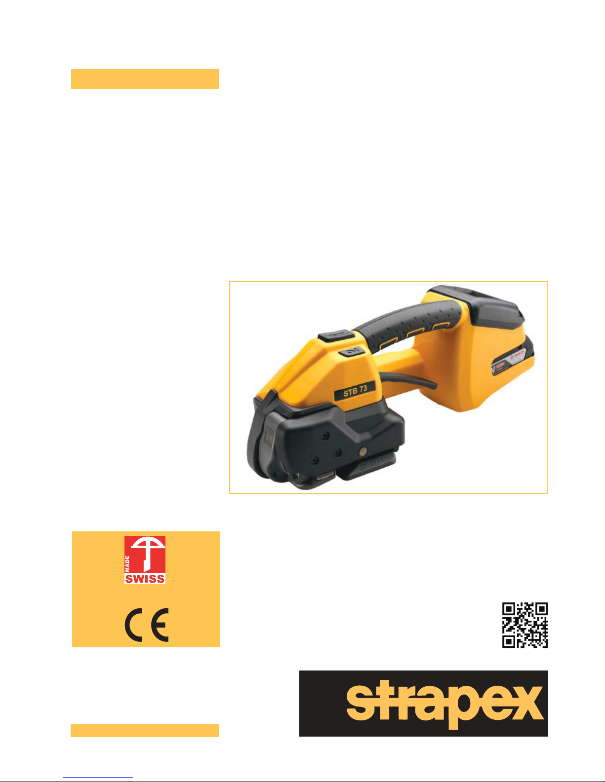
Battery-operated hand tool for plastic strapping
STB 71
STB 73
STB 75
Operating instructions
English
Patent pending
www.strapex-stb.com
Page 2

2 of 28
V 03.17
STRAPEX STB 71/73/75ENGLISH
Translation of original manual according to "Machine Directive" 2006/42/EEC.
Read the operating instructions carefully.
These operating instructions are part of the product and therefore should be kept for later use or a
future owner.
Validity:
● STB 71 from Series no A/17020001
● STB 73 from Series no B/17020001
● STB 75 from Series no C/17020001
Manufacturer
Strapex
c/o Signode Industrial Group GmbH
Orgapack Packaging Technology
Silbernstrasse 14
Postfach 595
8953 Dietikon 1, SWITZERLAND
www.sigpse.com
Page 3

3 of 28
V 03.17
STRAPEX STB 71/73/75
ENGLISH
1 General information 4
2 Safety 5
2.1 Use for the intended purpose 5
2.2 Working safely 5
2.3 Safety instructions 5
2.4 General safety warnings for power tools 7
3 Description 9
3.1 Design 9
3.2 Function 10
3.3 Scope of delivery 10
3.4 Accessories 11
4 Preparing for operation and settings 12
4.1 Battery 12
4.2 Setting the operating mode 13
4.3 Setting strap tension 14
4.4 Setting soft tension 15
4.5 Setting welding time 15
4.6 Switching touch-pad lock on and off 15
4.7 Select Favorite 16
4.8 Sleep mode 16
5 Operating instructions 17
5.1 Strapping 17
5.2 Checking the seal 19
5.3 Setting the strap width 20
6 Preventive and corrective maintenance 23
6.1 Preventive maintenance schedule 23
6.2 Cleaning the tool 23
6.3 Re-greasing the tool 23
6.4 Cleaning/replacing the tension wheel 23
6.5 Cleaning/replacing the tooth plate 24
6.6 Replacing the knife 25
6.7 Tool reset 25
6.8 Troubleshooting 26
7 Technical data 27
8 EC Declaration of Conformity (copy)
28
Table of contents
Page 4
4 of 28
V 03.17
STRAPEX STB 71/73/75ENGLISH
1 General information
Meaning of warning symbols, usage conventions
DANGER
Indicates a hazard with a high level of risk, which, if not avoided, will result in death or
serious injury.
WARNING
Indicates a hazard with a moderate level of risk, which, if not avoided, may result in death
or serious injury.
CAUTION
Indicates a hazard with a minor level of risk, which, if not avoided, may result in minor or
moderate injury
ATTENTION
Indicates a situation that can lead to material damage or poor operating results.
Indicates useful, supplementary information.
► This symbol identies action steps.
– This symbol indicates results from action steps.
● This symbol identies list items.
Disposal and environmental protection
This tool is manufactured without any physical or
chemical substances which could be dangerous
to health.
It is important to protect health and also promote
the reuse and environmentally-appropriate recycling of waste. The following harmonised standards have also been taken into consideration:
● Directive 2011/65/EU of 8 June 2011 on the restriction of the use of certain hazardous substances
in electrical and electronic equipment (RoHS II).
● Directive 2012/19/EU of 4 July 2012 on waste electrical and electronic equipment (WEEE II).
The legal prescriptions for disposal of all parts must be observed.
► Chargers and batteries should be sorted for environmentally-friendly recycling.
► Observe notes, warnings and instructions of the battery manufacturer.
!
Page 5
5 of 28
V 03.17
STRAPEX STB 71/73/75
ENGLISH
2 Safety
2.1 Use for the intended purpose
These tools are intended for the strapping of packaged items such as packages, pallet loads etc. The
tools are intended for strapping with plastic packaging straps (polypropylene and polyester) (Section
7). Only use these tools as described in these operating instructions.
2.1.1 Possible misuse
● Do not use steel straps with these tools.
● Do not lift, hang or pull packaged goods by the straps.
● Do not modify tools without prior authorisation.
● Do not use these tools to compress goods.
2.2 Working safely
The operating instructions must always be available at the place of operation of the
strapping tool. They must be read and observed by all persons working with or in the
vicinity of the strapping tool.
Preventive and corrective maintenance on the tool may only be carried out by trained
personnel.
In addition to the operating instructions, the applicable local rules for accident prevention and safe and professional work must be observed.
The operator or his supervisor is responsible for safe strapping and the correct strap selection (Section
7) for the package, depending on its dimensions, weight, edges and stability and the way it will be
transported and stored. Only the strap specications (Section 7) specied for the tool type should be
used. The tools should be adjusted appropriately for the strap used and the package (Section 4). The
operator is responsible for the correct tool settings and adjustments.
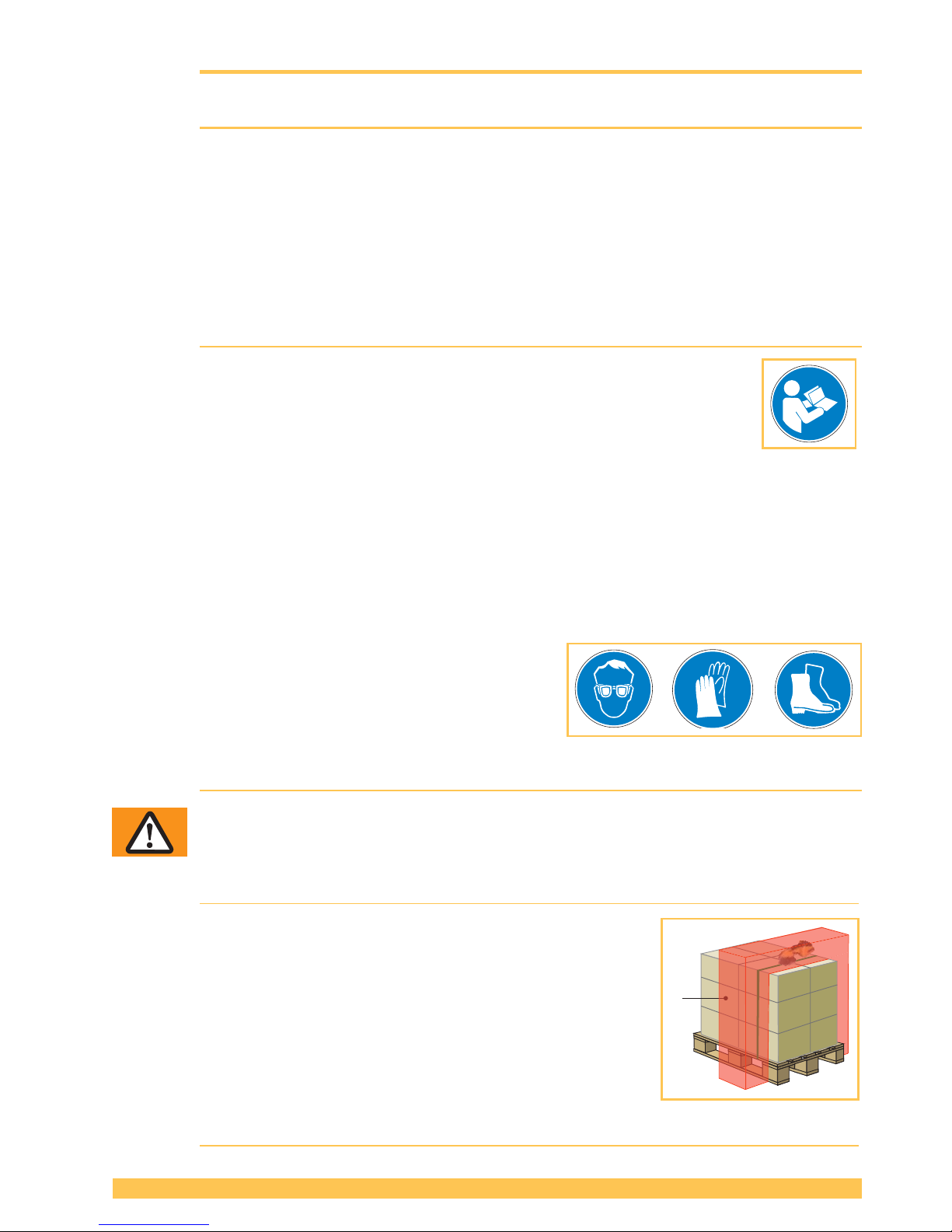
Wear protective equipment
► When operating the tool, wear eye and hand protection
(cut-proof gloves) and safety shoes.
2.3 Safety instructions
WARNING
Read all safety warnings and all instructions in this operating instructions and in
the battery charger operating instructions.
Failure to follow the warnings and instructions may result in electric shock, re and/or
serious injury. Following hazards can result in serious injuries:
Strap tensioning or strapping, danger of jamming and
crushing
Do not place hands or other body parts between the strap and
the packaged goods during the strapping process. Ensure that
there are no other persons in the hazard zone (1).
For an emergency stop in the case of danger (trapped
person):
● To release the strap tension (before welding), actuate the
rocker lever. In operating mode AUTO, also the tensioning
or welding button can be pressed again to stop strap
tensioning.
● After welding, cut the strap using a suitable tool (strap cutter).
1
Page 6
6 of 28
V 03.17
STRAPEX STB 71/73/75ENGLISH
WARNING
Following hazards can result in injuries:
Loose and falling packaged goods in the case of faulty seal
Check the weld seal. Never transport packaged goods if loads looks unbalanced or
improper (Section 5.2).
Risk of explosion in EX (Explosive) zones
The tool must not be used in areas where explosions can occur as a result ot the environment or products being used.
Moving parts of the tensioning device, risk of crushing
Do not grasp in the area of moving parts.
Breaking straps, risk of injury
When being tensioned the strap may break and whip out. Do not stand in line with the
strap while it is being tensioned. Wear eye protection.
Strap ends snapping back, risk of injury
When cutting the strap, hold the upper portion and stand safely away from the strap. Do
not stand in line with the strap while it is being tensioned. Wear eye protection.
Compressed air for cleaning work, risk of injury
When cleaning with compressed air, no air must penetrate the body via skin lesions. Use
a blow gun with a multi hole nozzle. Wear eye protection.
CAUTION
The following dangers can result in minor or moderate injury:
Noise exposure
Wearing hearing protection is recommended.
Vibration exposure
The vibration level specied in these instructions has been measured according to a
measurement method standardised in EN 60745 and can be used for the comparison of
power tools with each other. It is also suitable for a preliminary estimation of the vibration
load.
The vibration emission value measured may deviate from the specied value depending
on the actual application, the strap used and the manner of operation. Under certain circumstances, the vibration load may be increased over the entire work period. For a more
accurate assessment of the vibration load, the times should also be considered when the
device is switched off, or is running but not actually being used. This could reduce the
vibration load signicantly over the entire work period.
Dene additional safety measures against the effect of vibrations for the protection of the
operator, such as, for example: maintenance of the power tool, keep hands warm and
organisation of work processes.
ATTENTION
Avoid damage to the tool:
Water damage
Do not clean the tool with water or steam. When using the tool outdoors, protect it from
rain.
Use only original spare parts
Using non-original spare parts will void the warranty and any liability.
!
Page 7

7 of 28
V 03.17
STRAPEX STB 71/73/75
ENGLISH
2.4 General safety warnings for power tools
WARNING! Read all safety warnings and all instructions. Failure to follow the war-
nings and instructions may result in electric shock, re and/or serious injury.
Save all warnings and instructions for future reference.
The term “power tool” in the warnings refers to your mains-operated (corded) power tool or batteryoperated (cordless) power tool.
2.4.1 Work area safety
a) Keep the work area clean and well lit. Cluttered or dark areas invite accidents.
b) Do not operate power tools in explosive atmospheres, such as in the presence of ammab-
le liquids, gases or dust. Power tools create sparks which may ignite the dust or fumes.
c) Keep children and bystanders away while operating a power tool. Distractions can cause you
to lose control.
2.4.2 Electrical safety
a) Power tool plugs must match the outlet. Never modify the plug in any way. Do not use any
adapter plugs with earthed (grounded) power tools. Unmodied plugs and matching outlets
will reduce the risk of electric shock.
b) Avoid body contact with earthed or grounded surfaces such as pipes, radiators, ranges and
refrigerators. There is an increased risk of electric shock if your body is earthed or grounded.
c) Do not expose power tools to rain or wet conditions. Water entering a power tool will increase
the risk of electric shock.
d) Do not abuse the cord. Never use the cord for carrying, pulling or unplugging the power
tool. Keep the cord away from heat, oil, sharp edges or moving parts. Damaged or entangled
cords increase the risk of electric shock.
e) When operating a power tool outdoors, use an extension cord suitable for outdoor use. Use
of a cord suitable for outdoor use reduces the risk of electric shock.
f) If operating a power tool in a damp location is unavoidable, use a residual current device
(RCD) protected supply. Use of an RCD reduces the risk of electric shock.
2.4.3 Personal safety
a) Stay alert, watch what you are doing and use common sense when operating a power tool.
Do not use a power tool while you are tired or under the inuence of drugs, alcohol or
medication. A moment of inattention while operating power tools may result in serious personal
injury.
b) Use personal protective equipment. Always wear eye protection. Protective equipment such
as dust masks, non-skid safety shoes, hard hat, or hearing protection used for appropriate conditions will reduce personal injuries.
c) Prevent unintentional starting. Ensure the switch is in the off-position before connecting to
the power source and/or battery pack, picking up or carrying the tool. Carrying power tools
with your nger on the switch or energising power tools that have the switch on invites accidents.
d) Remove any adjusting key or wrench before turning the power tool on. A wrench or a key left
attached to a rotating part of the power tool may result in personal injury.
e) Do not overreach. Keep proper footing and balance at all times. This enables better control of
the power tool in unexpected situations.
f) Dress properly. Do not wear loose clothing or jewellery. Keep your hair, clothing and gloves
away from moving parts. Loose clothes, jewellery or long hair can be caught in moving parts.
g) If devices are provided for the connection of dust extraction and collection facilities, ensure
these are connected and properly used. Use of dust collection can reduce dust-related hazards.
Page 8

8 of 28
V 03.17
STRAPEX STB 71/73/75ENGLISH
2.4.4 Power tool use and care
a) Do not force the power tool. Use the correct power tool for your application. The correct
power tool will do the job better and safer at the rate for which it was designed.
b) Do not use the power tool if the switch does not turn it on and off. Any power tool that cannot
be controlled with the switch is dangerous and must be repaired.
c) Disconnect the plug from the power source and/or the battery pack from the power tool be-
fore making any adjustments, changing accessories, or storing power tools. Such preventive safety measures reduce the risk of starting the power tool accidentally.
d) Store idle power tools out of the reach of children and do not allow persons unfamiliar with
the power tool or these instructions to operate the power tool. Power tools are dangerous in
the hands of untrained users.
e) Maintain power tools. Check for misalignment or binding of moving parts, breakage of parts
and any other condition that may affect the power tool’s operation. If damaged, have the
power tool repaired before use. Many accidents are caused by poorly maintained power tools.
f) Keep cutting tools sharp and clean. Properly maintained cutting tools with sharp cutting edges
are less likely to bind and are easier to control.
g) Use the power tool, accessories and tool bits etc. in accordance with these instructions,
taking into account the working conditions and the work to be performed. Use of the power
tool for operations different from those intended could result in a hazardous situation.
2.4.5 Battery tool use and care
a) Recharge only with the charger specied by the manufacturer. A charger that is suitable for
one type of battery pack may create a risk of re when used with another battery pack.
b) Use power tools only with specically designated battery packs. Use of any other battery
packs may create a risk of injury and re.
c) When the battery pack is not in use, keep it away from other metal objects, like paper clips,
coins, keys, nails, screws or other small metal objects, that can make a connection from
one terminal to another. Shorting the battery terminals together may cause burns or a re.
d) Under abusive conditions, liquid may be ejected from the battery; avoid contact. If contact
accidentally occurs, ush with water. If liquid contacts eyes, additionally seek medical help.
Liquid ejected from the battery may cause irritation or burns.
2.4.6 Service
a) Have your power tool serviced by a qualied repair person using only identical replacement
parts. This will ensure that the safety of the power tool is maintained.
Page 9
9 of 28
V 03.17
STRAPEX STB 71/73/75
ENGLISH
3 Description
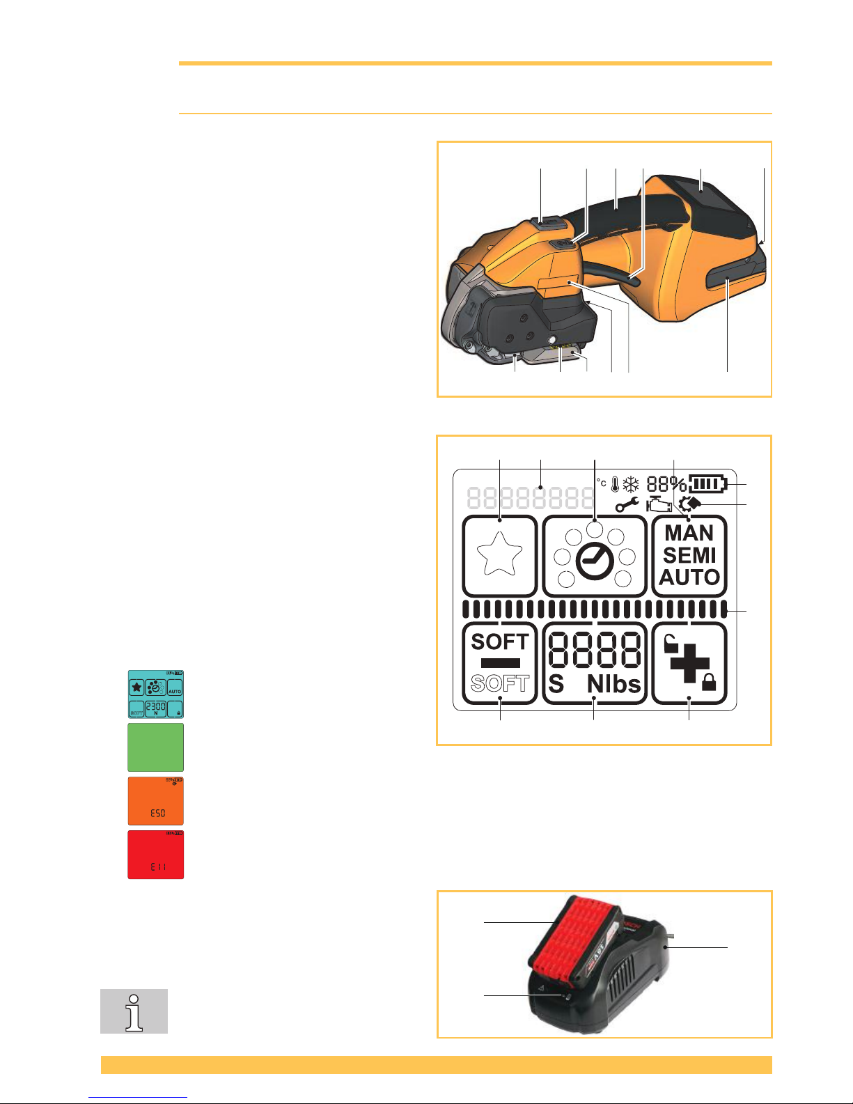
3.1 Design
1 Tensioning button
2 Welding button
3 Handle
4 Rocker lever
5 Operating panel
6 Unlock button, battery
7 Battery
8 Type designation
9 Strap guide indicator
10 Serial number (XJJMMYYYY)
X A=STB 71, B=STB 73, C=STB75
JJ Year
MM Month
YYYY consecutive number
11 Welding device
12 Tensioning device
Operating panel
1 Keypad "Favourite"
2 Keypad "Welding time"
3 Keypad "Operating mode"
4 Keypad "Plus & Keylock"
5 Keypad "Tensioning force"
6 Keypad "Minus & Soft tension"
a Display "Battery charge status"
b Display "Information symbols"
c Status indicator bar “Tensioning/Welding“
d Display "Messages"
Background lighting
● Display activated.
● Welding process is nished, tool
can be removed (Section 5.1).
● Application error: temporary system error, can be rectied by the operator (Section 6.8).
● Tool fault: static system error, rectify error (Section 6.8). If the error cannot be rectied
Service department.
Battery and charger
1 Charger
2 Battery
3 LED indicator
For detailed information, refer to the
operating instructions for the battery
and the charger.
a
b
c
123
65 4
d
1 2 3 4 5 6
789101112
1
Page 10
10 of 28
V 03.17
STRAPEX STB 71/73/75ENGLISH
3.2 Function
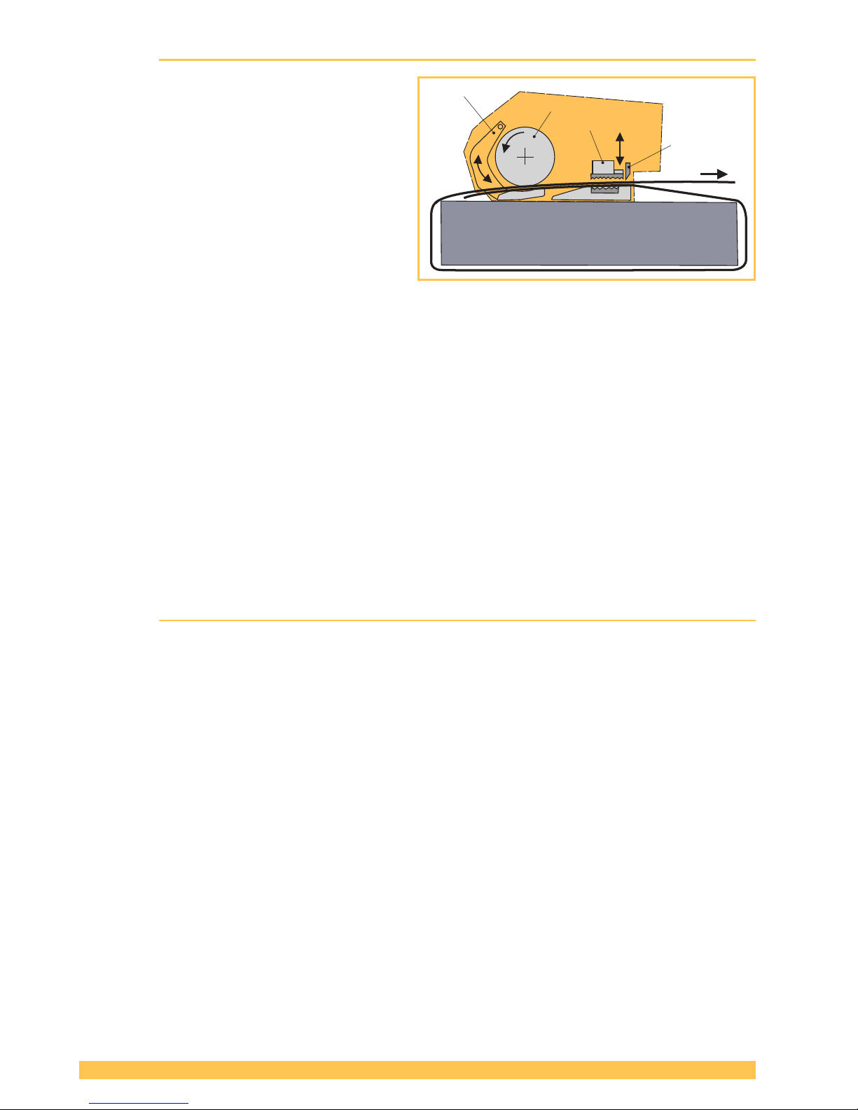
● The rocker lever is used to open the tension-
ing device so that the straps can be inserted.
● The straps are clamped between the tooth
plate on the rocker (1) and the tension wheel
(2).
● The strap is tensioned by the tension wheel
(2) rotating in a counter-clockwise direction.
● The straps are welded in the welding device
(3) using the friction welding process.
● The upper strap is cut off by the knife (4).
● You can choose between three operating
modes: (Section 4.2)
● Semi-automatic (standard/factory setting)
● Fully automatic
● Manual
● You can also choose between two tension
ranges: (Section 4.3/4.4)
● Standard tension for PET straps
● Soft tension for PP straps (Tension wheel
starts slowly. Prevents excessive dirt and
grime build up in tool.)
● The welding time can be set.
(Section 4.5)
● The tools can be operated with different strap
widths (Section 7):
● STB 71: 9–10 mm, 12–13 mm (3/
8
″,
1
/
2
″)
● STB 73: 12–13 mm, 15–16 mm (1/
2
″,
5
/
8
″)
STB 75: 15–16 mm, 18–19 mm (5/
8
″,
3
/
4
″)
3.3 Scope of delivery
For strapping tool STB 71 / STB 73: ● Battery 18 V/2.0 Ah Li-Ion Part no 2187.011
● Battery charger GAL 1880 CV EU Part no 2188.020
or for USA version: ● Battery 18 V/2.0 Ah (US) BAT612 Part no 2187.012
● Battery charger (US) BC1880 Part no 2188.021
or for Japan version: ● Battery charger GAL 1880 CV (JP) Part no 2188.022
or for Australia version: ● Battery charger GAL 1880 CV(AUS) Part no 2188.023
Tool kit consisting of: ● Wire brush
● Screwdriver Torx T20
● Offset screwdriver
Part no 1821.901.004
Part no 1821.901.010
Part no 1821.901.007
Page 11
11 of 28
V 03.17
STRAPEX STB 71/73/75
ENGLISH
For strapping tool STB 75: ● Battery 18 V/4.0 Ah Li-Ion Part no 2187.003
● Battery charger GAL 1880 CV EU Part no 2188.020
or for USA version: ● Battery 18 V/4.0 Ah (US) BAT620 Part no 2187.004
● Battery charger (US) BC1880 Part no 2188.021
or for Japan version: ● Battery charger GAL 1880 CV (JP) Part no 2188.022
or for Australia version: ● Battery charger GAL 1880 CV (AUS) Part no 2188.023
Tool kit consisting of: ● Wire brush
● Screwdriver Torx T20
● Offset screwdriver
Part no 1821.901.004
Part no 1821.901.010
Part no 1821.901.007
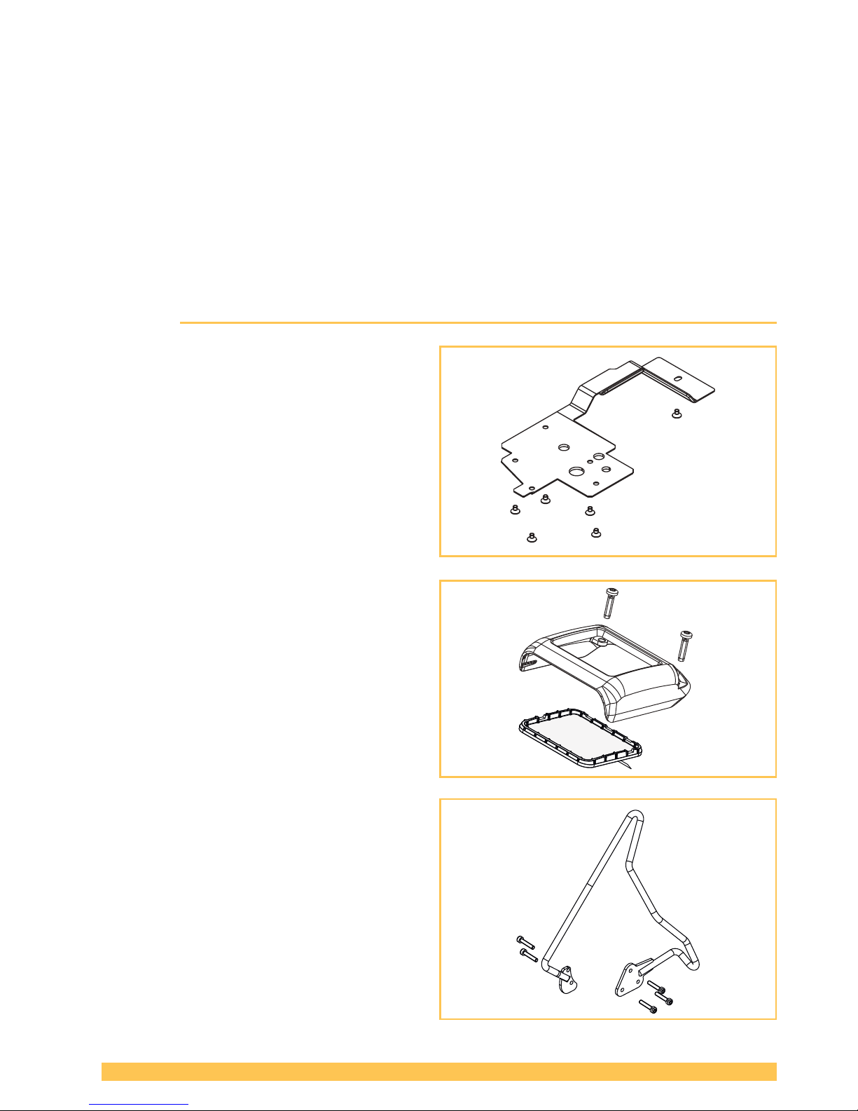
3.4 Accessories
● Protection plate set
Part no 2189.010
● Protection cover set
Part no 2189.011
● Suspension bow set
Part no 2189.012
Page 12
12 of 28
V 03.17
STRAPEX STB 71/73/75ENGLISH
4 Preparing for operation and settings
4.1 Battery
For detailed information, see the separately enclosed operating instructions for the battery and the
charger.
WARNING
Only use Bosch batteries and chargers as described in this manual (Section 3.3). Use of
other batteries/chargers can result in injury or re. To avoid the risk of personal injury or
re, read the battery charger operating instructions prior using the charger and battery.
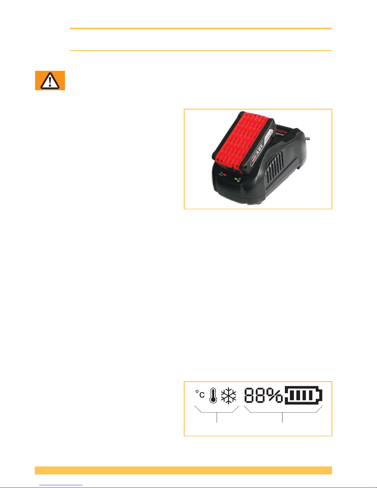
4.1.1 Charging the battery
► Connect charger to mains.
– Green LED illuminates (charger ready for
use).
► Insert battery in charger.
– Green LED ashes: Battery is being
charged.
– Green LED illuminates continuously:
Battery is fully charged.
– Red LED illuminates continuously: Battery
temperature outside charge-temperature
range.
– Red LED ashes: see operating instruc-
tions of charger.
● Charging time: Charging of empty battery: approx. 15–35 min.
● Ideal battery temperature during charging process: 15–40 °C (59–104 °F)
● Avoid battery temperatures below 0 °C (32 °F) and over +45 °C (113 °F) during the charging
process.
● The battery can be charged at any time, regardless of the charge status.
4.1.2 Inserting/removing battery in/from tool
► Inserting the battery: Insert the charged battery into the tool. The unlock button must engage in the
second step (in the rst step the battery is held in place in the tool, but without electrical contact).
– The displays on the operating panel illuminate.
● If the tool is not used for approx. ve minutes the display changes into sleep mode. Cancelling
sleep mode: Lift rocker lever.
● If the tool is not used for a long period (days) the battery must be removed from the tool and
charged/stored in the battery charger.
► Removing the battery: Press the unlock button and remove the battery at the same time.
4.1.3 Checking the charge status
► LED display "Battery charge status" on oper-
ating panel, with battery inserted:
– The charge status is shown in % and by a
progress bar (1)
– Below 10% minimum charge (battery must
be charged)
– The information symbols (2) only appear if
a corresponding situation is occuring (Section 6.8).
2 1
Page 13
13 of 28
V 03.17
STRAPEX STB 71/73/75
ENGLISH
4.2 Setting the operating mode
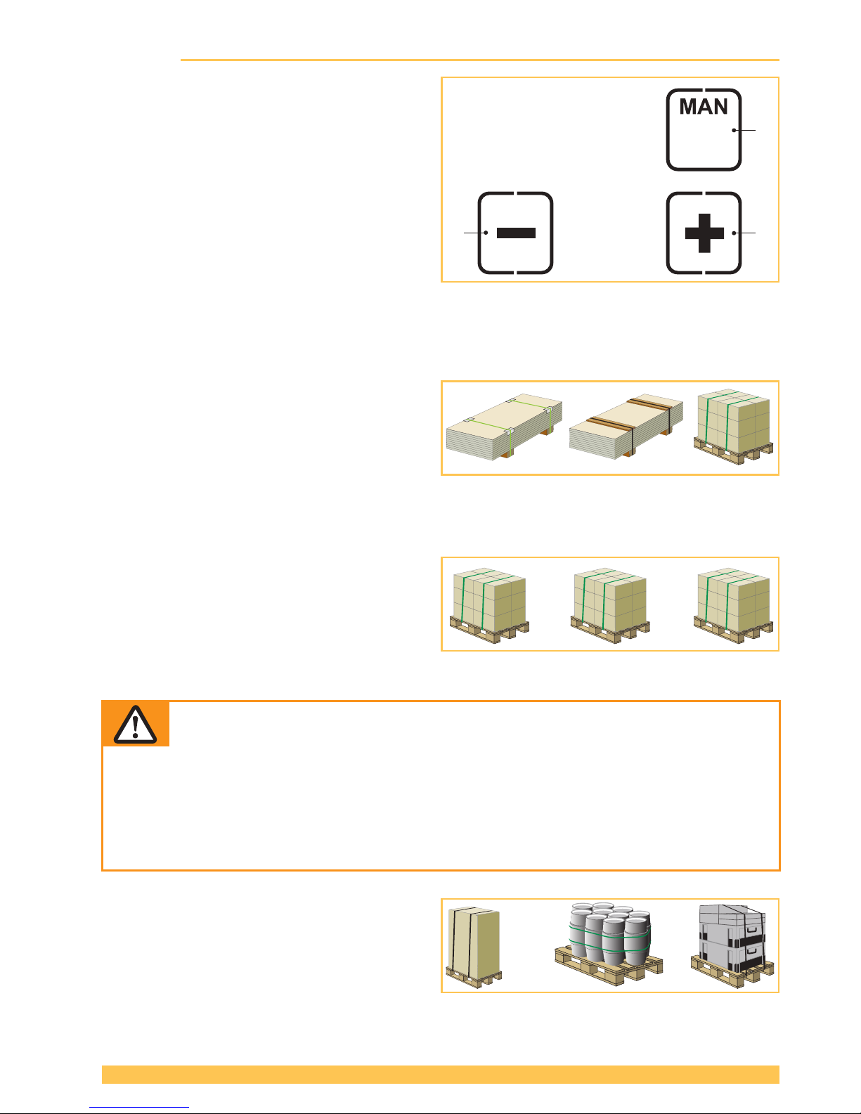
► Press the "Operating mode" button (1).
– Unused displays disappear.
– The currently set operating mode ashes
for 5 seconds.
– + and – appear.
► Press the + (2) or – (3) button until the desired
operating mode is displayed.
– MAN / SEMI / AUTO
► By pressing the "Operating mode" button (1)
again, or after waiting for a period of 5 seconds, the set mode is saved.
Every operating mode can also be selected
for the "Soft tension" tension range (Section 4.4).
Select an operating mode for your application in accordance with the descriptions below:
(The illustrations are symbolic. Actual use may deviate from these).
● SEMI–Semi-automatic strapping
(standard/factory setting)
The tensioning button (Section 3.1) must be
pressed and held down until the set tension force
has been reached. The straps are then automatically welded and the upper strap is cut off. It can
be welded manually at any time by pressing the
welding button.
Recommended for similar packaged goods.
● AUTO–Fully automatic strapping
The tensioning button (Section 3.1) must only
be briey pressed (touched). This triggers the
tensioning process. Once the set tension force
has been reached, the straps are automatically
welded and the upper strap is cut off.
Recommended for large quantities of identical packaged goods.
WARNING
Strap tensioning or strapping, danger of jamming and crushing
Do not place hands or other body parts between the strap and the packaged goods
during the strapping process. Ensure that there are no other persons in the hazard zone
(Section 2.3).
For an emergency stop in the case of danger (trapped person):
To release the strap tension (before welding), actuate the rocker lever. In operating mode
AUTO, also the tensioning or welding button can be pressed again. After welding, cut the
strap using a tool (strap cutter).
● MAN–Manual
The tensioning button (Section 3.1) must be
pressed and held down until the desired strap
tension has been reached. The welding button
(Section 3.1) must then be briey pressed so that
the straps are welded and the upper strap is cut
off.
Recommended for varying (soft, hard) packaged goods.
1
3
2
Page 14
14 of 28
V 03.17
STRAPEX STB 71/73/75ENGLISH
4.3 Setting strap tension
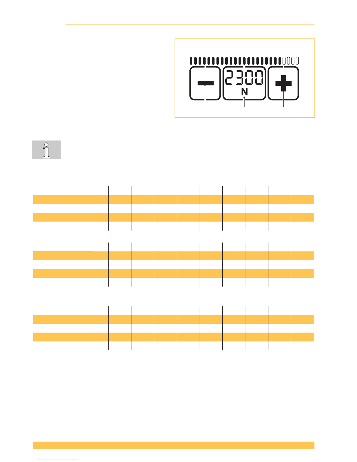
The set tension force is displayed continuously when the tool is ready for operation.
► Press "Tension force" button (2).
– The set tension force ashes for 5 sec-
onds.
– The + (1) and – (3) buttons appear.
– Unused displays disappear.
► Press the + (1) or – (3) button until the desired
tension force is displayed.
– The status indicator bar (4) shows the set
tension force in relation to the possible
maximum value.
► Save: Press the "Tension force" button (2) or
wait for 5 seconds.
● Switch between display in "N" or "lbf": Press the ashing "Tension force" button (2) for
two seconds.
● Every time the button is pressed an acoustic signal conrms the action.
● The tension force is displayed continuously when the tool is operational.
● Setting soft tension (Section 4.4).
STB 71: 1 2 3 4 5 6 7 8 9
Standard: N* 400 500 600 700 800 900 1000 1100 1200
lbf* 90 110 135 155 180 200 225 250 270
Soft N 150 225 300 375 450 525 600 675 750
lbf 33 50 67 85 100 120 135 150 165
STB 73: 1 2 3 4 5 6 7 8 9
Standard: N* 900 1100 1300 1500 1700 1900 2100 2300 2500
lbf* 200 250 290 340 380 430 470 520 560
Soft N 400 520 640 760 880 1000 1120 1240 1360
lbf 90 11 5 145 170 200 225 250 280 305
STB 75: 1 2 3 4 5 6 7 8 9
Standard: N* 1300 1700 2100 2500 2900 3300 3700 4100 4500
lbf* 290 380 470 560 650 740 830 920 1000
Soft N 400 550 700 850 1000 1150 1300 1450 1600
lbf 90 120 160 190 225 260 290 325 360
(rounded values)
* N = Newton, lbf = pound-force per square inch
4
123
Page 15
15 of 28
V 03.17
STRAPEX STB 71/73/75
ENGLISH
4.4 Setting soft tension
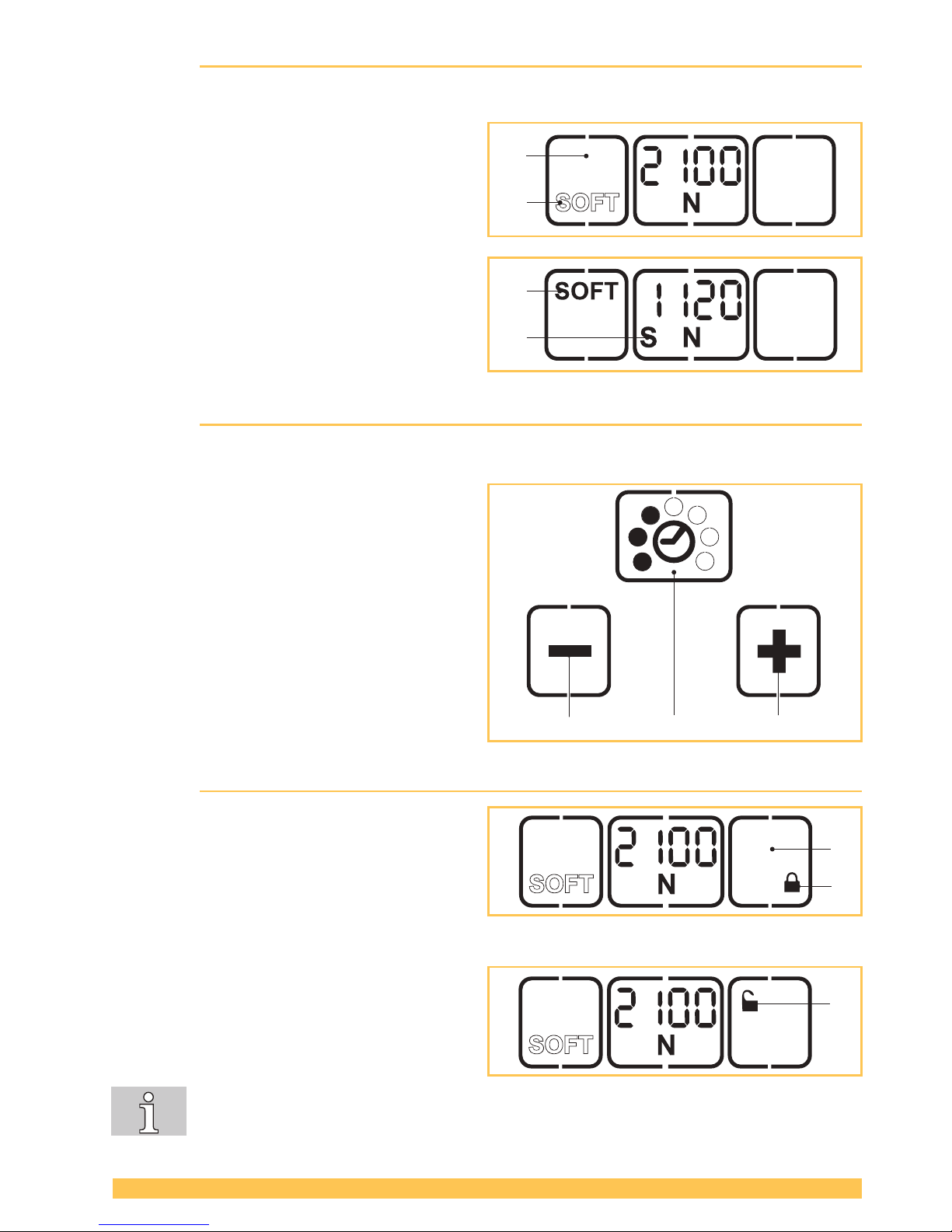
When soft tension is set the tension wheel starts more slowly and the tension force is reduced. This
prevents excessive soiling when PP straps are used.
► Press "Soft" button (1).
– The soft mode is deactivated when the
"SOFT" display (2) changes position and
is shown outlined.
► Press "Soft" button (1).
– The soft mode is activated when the
"SOFT" display (3) changes position and
is shown in bold.
– The displayed tension force is reduced
correspondingly.
– On the left under the tension force an "S"
(4) also appears.
4.5 Setting welding time
The set welding time is displayed continuously by means of lled dots when the tool is ready for operation.
► Press the "Welding time" button (2).
– Unused displays disappear.
– The lled dots of the currently set welding
time ash for 5 seconds.
– + and – appear.
► Press the + (1) or – (3) button and hold down
until the desired welding time is displayed.
► Save: Press the "Welding time" button (2) or
wait 5 seconds.
4.6 Switching touch-pad lock on and off
The touch pad can be locked to prevent unwanted
changing of the settings.
► Locking: Press the “Touch pad lock” button
(1) and hold down while pressing welding
button (Section 3.1, item 2) at the same time.
– The lock symbol (2) changes position and
is shown closed.
► Unlocking: Press the “Touch pad lock” button
(1) and hold down while pressing the welding
button (Section 3.1, item 2) at the same time.
– The lock symbol (3) changes position and
is shown open.
The favourite mode (Section 4.7) can be switched on even when the key lock is activated.
If the adjustment of the settings is not desired, the favourite level should be set in the
same way as the normal level.
1
2
3
4
123
2
1
3
Page 16
16 of 28
V 03.17
STRAPEX STB 71/73/75ENGLISH
4.7 Select Favorite
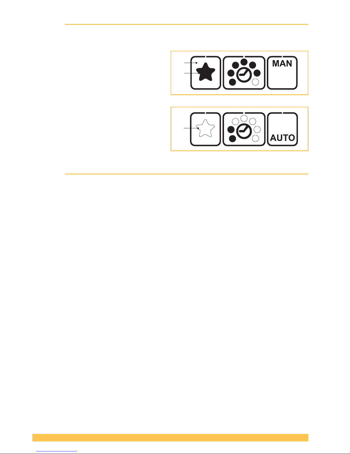
The "Favorite" function activates a second setting level whose parameters can be set freely as at the
main level. This allows the user to switch quickly from one tool setting to another.
Activating Favorite:
► Press the "Favorite" button (1).
– The star (2) changes from outlined to
lled.
– All parameters change to the values pre-
set at this setting level.
Deactivating Favorite:
► Press the "Favorite" button (1).
– The star (3) changes from lled to out-
lined.
– All parameters change to the values pre-
set at this setting level.
4.8 Sleep mode
To avoid unnecessary battery discharge, the tool switches to energy-saving mode within short time.
– The operating panel becomes dark (not Illuminated).
► Pressing the operating panel switches the energy-saving mode off again.
After approx. ve minutes without operation the tool switches to sleep mode.
– The operating panel is switched off (black).
► Actuating the rocker lever switches the sleep mode off again.
2
1
3
Page 17
17 of 28
V 03.17
STRAPEX STB 71/73/75
ENGLISH
5 Operating instructions
5.1 Strapping
Preconditions
● The tool is adjusted to the width of the strap to be used (Section 5.3).
● The charged battery is inserted (Section 4.1.2).
● The desired operating mode is set (Section 4.2.). In this description it is assumed that the selected
operating mode (default mode) is “SEMI” (semi-automatic).
● Desired tension force is set (Section 4.3).
● Desired welding time is set (Section 4.5).
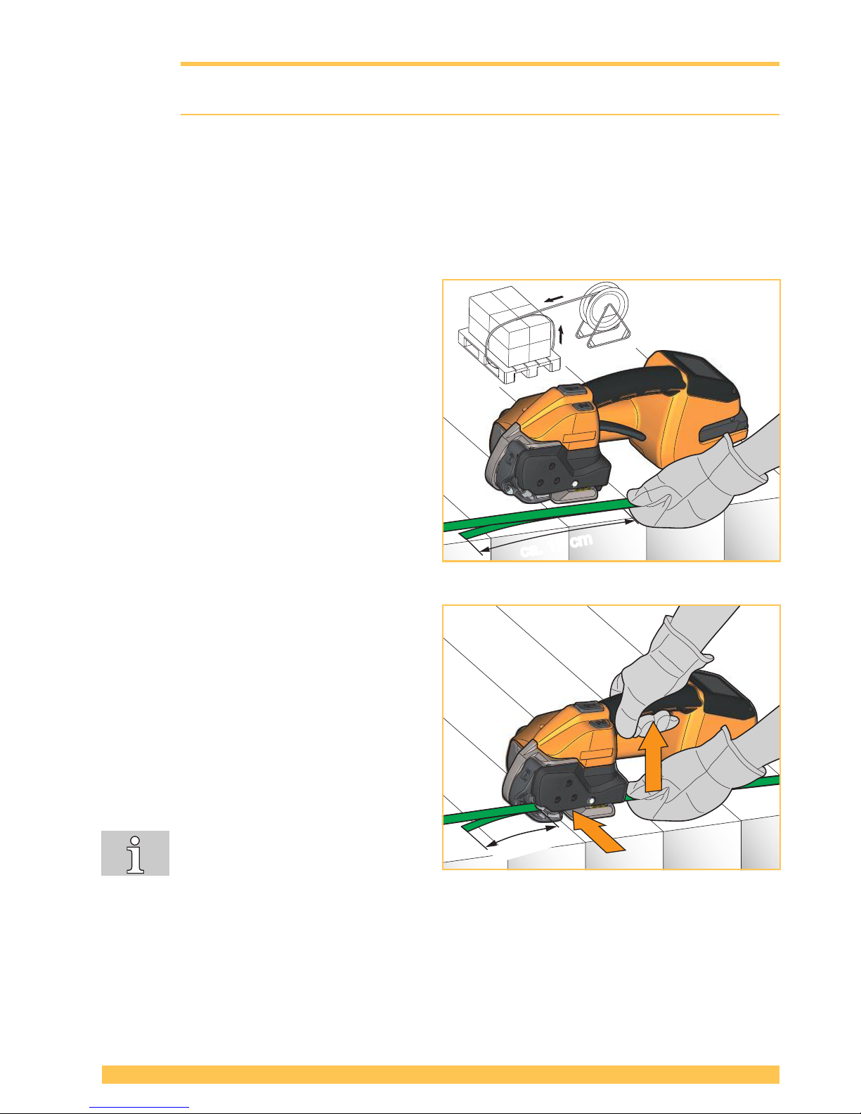
► Place the strap around the packaged goods.
► Grasp the straps at the top of the goods with
your left hand so that:
● The straps lie one above the other.
● The beginning of the strap lies underneath
and should project 15 cm (6”) beyond your
hand.
► Take the tool with your right hand.
► Lift rocker lever.
– Rocker of the tensioning device opens.
► Insert overlaid straps up to the end stop. The
strap coming from the dispenser lies above.
► Release rocker lever.
– The straps are clamped in the tensioning
device.
– The beginning of the strap should project
approx. 5 cm (2”).
If the strap is not inserted completely,
the strap guide indicator (Section 3.1,
item 9) shows a red eld. Insert the
strap completely. The strap guide indicator is black.
► Remove hands from the straps before tensioning!
ca. 15 cmca. 15 cm (6”)
ca. 5 cm (2”)
Page 18
18 of 28
V 03.17
STRAPEX STB 71/73/75ENGLISH
1.
2.
WARNING
Strap tensioning or strapping, danger of jamming and crushing
Do not place hands or other body parts between the strap and the packaged goods
during the strapping process. Ensure that there are no other persons in the hazard zone
(Section 2.3).
For an emergency stop in the case of danger (trapped person):
● To release the strap tension (before welding), actuate the rocker lever. In operating
mode AUTO, also the tensioning or welding button can be pressed again.
● After welding, cut the strap using a tool (strap cutter).
CAUTION
When being tensioned the strap may
break and whip out. Do not stand
in line with the strap while it is being
tensioned. Wear eye protection.
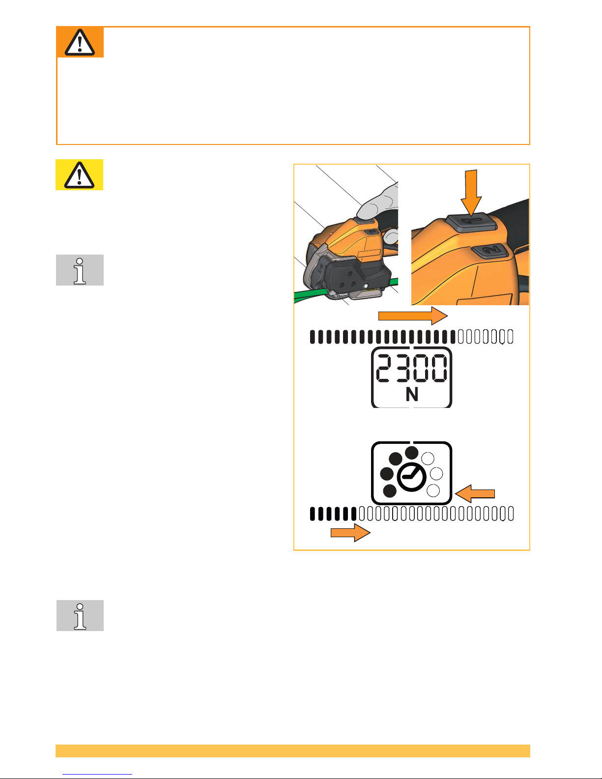
► Press the tensioning button and hold it down
until the set tension force has been reached.
The tension speed is variable and
depends on the pressure on the tensioning button (MAN/SEMI operating
mode).
Stopping/continuing the tensioning
process:
Release / press the tensioning button
again.
– The following information is displayed:
The set tension force and the status indi-
cator bar with the reached tension force in
relation to the set tension force.
– The tensioning process is ended when the
status indicator bar has been completely
lled.
► The tensioning button can now be released.
– The straps are now automatically welded
and the upper strap is cut off.
– The following information is displayed:
The set welding time and the status
indicator bar.
– The welding process is ended when the
status indicator bar has been complete-
ly lled (1.) After this the cooling time begins (2.). At the end of the cooling time an acoustic
signal sounds and the operating panel lights up green for a second.
● Welding without strap tension: Press the tensioning button briey, then press the weld-
ing button (Section 3.1, item 2).
Page 19
19 of 28
V 03.17
STRAPEX STB 71/73/75
ENGLISH
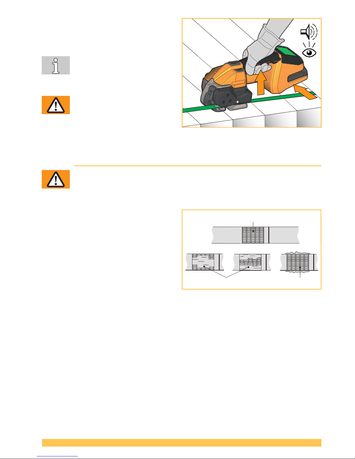
► After the display turns green and an acoustic
signal sounds the cooling time is ended. Lift
rocker lever.
– Rocker of the tensioning device opens.
After lifting the rocker lever, do not
re-tension (do not press the tensioning
button any more).
► Swivel the tool to the right away from the
strapping.
WARNING
If the tool is removed too early the display turns orange with error code and
an acoustic signal sounds repeatedly
(Section 6.8).
► Carry out a visual sealing inspection (Section 5.2)
5.2 Checking the seal
WARNING
Never transport or move packaged goods with improperly performed strapping /
weld sealing - serious injuries may result.
Perform sealing check after each strapping.
► Perform sealing check by visual inspection.
1 Good seal (the entire sealing area has been
cleanly welded, without excess material being
forced out sideways).
2 Poorly welded seal (weld not over entire
sealing area), welding time too short.
3 Poorly welded seal (excess material has
been forced out sideways), welding time too
long.
In the case of straps with poorly welded seals:
► Check the welding time setting (Section 4.5).
► Strapping with poorly welded seals must be performed again.
► Check strap type (Section 7).
► If good welding is not achieved, the tool must be checked by an authorized service center.
Page 20
20 of 28
V 03.17
STRAPEX STB 71/73/75ENGLISH
5.3 Setting the strap width
The tools can be operated with the following strap widths:
● STB 71: 9–10 mm, 12–13 mm (3/
8
″,
1
/
2
″)
● STB 73: 12-13 mm, 15-16 mm (1/
2
″,
5
/
8
″)
● STB 75: 15-16 mm, 18-19 mm (5/
8
″,
3
/
4
″)
5.3.1 STB 71: Change strap width from 9 mm to 13 mm (3/
8
″ to
1
/
2
″)
Required parts Order number
Strap guide front 13 mm (
1
/
2
″) (3) 1832.031.051
Strap guide rear 13 mm (
1
/
2
″) (8) 1832.041.019
Strap guide rear 13 mm (
1
/
2
″) (9) 1832.042.043
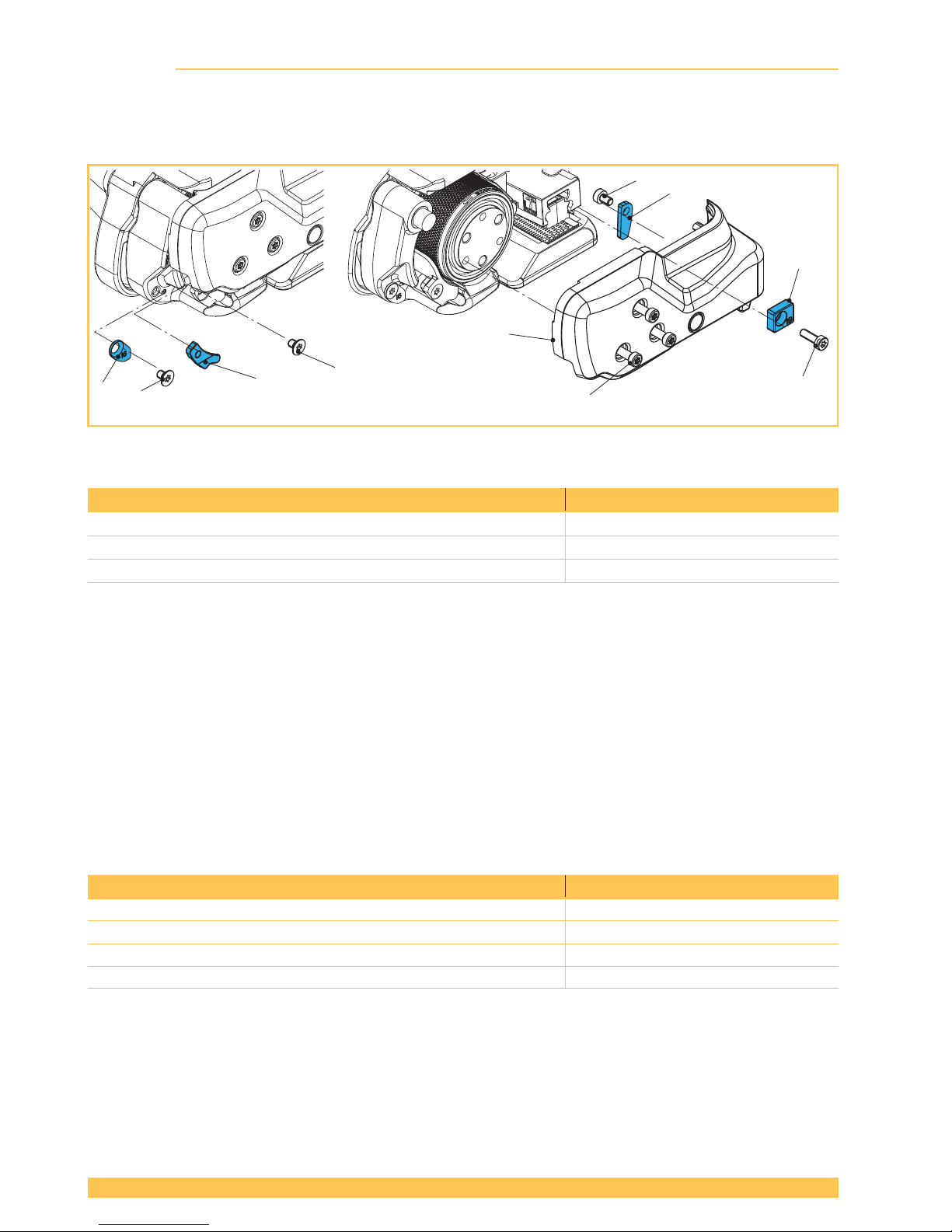
► Remove battery from tool. Remove three cylinder screws Torx (6). Lift rocker lever towards the
handle, remove cylinder screw Torx (7) and strap guide rear 9 mm (
3
/
8
″) (8).
► Remove side cover (5).
► Remove counter-sunk screw Torx (2) and strap guide front 9 mm (1).
► Remove counter-sunk screw Torx (4) and strap guide front 9 mm (3). Fit strap guide front 13 mm
(3) (secure counter-sunk screw with Loctite 222).
► Remove cylinder screw Torx (10) and strap guide rear 9 mm (9). Fit strap guide rear 13 mm (9)
(secure cylinder screw with Loctite 222).
► Fit side cover (5) (secure cylinder screw with Loctite 222). Install strap guide rear 13 mm (8).
STB 71: Change from 13 mm to 9 mm (
1
/
2
″ to
3
/
8
″)
Required parts Order number
Strap guide front 9 mm (
3
/
8
″) (1) 1832.031.121
Strap guide rear 9 mm (
3
/
8
″) (8) 1832.041.020
Strap guide rear 9 mm (
3
/
8
″) (9) 1832.042.047
Counter-sunk screw Torx, M4x6 (2) (4) 1912.204.064
► Remove battery from tool. Remove three cylinder screws Torx (6). Lift rocker lever towards the
handle, remove cylinder screw Torx (7) and strap guide rear 13 mm (
1
/
2
″) (8).
► Remove side cover (5).
► Fit strap guide front 9 mm (1) (secure counter-sunk screw with Loctite 222).
STB 75
1
2
3
4
5
6
7
10
9
8
Page 21
21 of 28
V 03.17
STRAPEX STB 71/73/75
ENGLISH
► Fit strap guide rear 9 mm (9) (secure cylinder screw with Loctite 222).
► Fit side cover (5) (secure cylinder screw with Loctite 222). Install strap guide rear 9 mm (8).
5.3.2 STB 73: Change from 13 mm to 16 mm (
1
/
2
″ to
5
/
8
″)
Required parts Order number
Strap guide rear 16 mm (5/
8
″) (8) 1832.041.018
► Remove battery from tool. Remove three cylinder screws Torx (6). Lift rocker lever towards the
handle, remove cylinder screw Torx (7) and strap guide rear 13 mm (
1
/
2
″) (8).
► Remove side cover (5).
► Remove counter-sunk screw Torx (2) and strap guide front 13 mm (1).
► Remove counter-sunk screw Torx (4) and strap guide front 13 mm (3).
► Remove cylinder screw Torx (10) and strap guide rear 13 mm (9).
► Fit side cover (5) (secure cylinder screw with Loctite 222). Install strap guide rear 16 mm (8).
STB 73: Change from 16 mm to 13 mm: (
5
/
8
″ to
1
/
2
″)
Required parts Order number
Strap guide front 13 mm (
1
/
2
″) (1) 1832.031.116
Strap guide front 13 mm (
1
/
2
″) (3) 1832.031.051
Strap guide rear 13 mm (
1
/
2
″) (9) 1832.042.043
Strap guide rear 13 mm (
1
/
2
″) (8) 1832.041.019
Counter-sunk screw Torx, M4x6 (2) (4) 1912.204.064
► Remove battery from tool. Remove three cylinder screws Torx (6). Lift rocker lever towards the
handle, remove cylinder screw Torx (7) and strap guide rear 16 mm (
5
/
8
″) (8).
► Remove side cover (5).
► Fit strap guide front 13 mm (1) (secure counter-sunk screw with Loctite 222).
► Fit strap guide front 13 mm (3) (secure counter-sunk screw with Loctite 222).
► Fit strap guide rear 13 mm (9) (secure cylinder screw with Loctite 222).
► Fit side cover (5) (secure cylinder screw with Loctite 222). Install strap guide rear 13 mm (8).
Page 22
22 of 28
V 03.17
STRAPEX STB 71/73/75ENGLISH
5.3.3 STB 75: Change from 16 mm to 19 mm (5/
8
″ to
3
/
4
″)
Required parts Order number
Strap guide rear 19 mm (3/
4
″) (8) 1832.041.021
► Remove battery from tool. Remove three cylinder screws Torx (6). Lift rocker lever towards the
handle, remove cylinder screw Torx (7) and strap guide rear 16 mm (
5
/
8
″) (8).
► Remove side cover (5).
► Remove counter-sunk screw Torx (2) and strap guide front 16 mm (1).
► Remove counter-sunk screw Torx (4) and strap guide front 16 mm (3).
► Remove cylinder screw Torx (10) and strap guide rear 16 mm (9).
► Fit side cover (5) (secure cylinder screw with Loctite 222). Install strap guide rear 19 mm (8).
STB 75: Change from 19 mm to 16 mm (
3
/
4
″ to
5
/
8
″)
Required parts Order number
Strap guide front 16 mm (
5
/
8
″) (1) 1832.031.117
Strap guide front 16 mm (
5
/
8
″) (3) 1832.031.067
Strap guide rear 16 mm (
5
/
8
″) (9) 1832.042.048
Strap guide rear 16 mm (
5
/
8
″) (8) 1832.041.022
Counter-sunk screw Torx, M4x6 (2) (4) 1912.204.064
► Remove battery from tool. Remove three cylinder screws Torx (6). Lift rocker lever towards the
handle, remove cylinder screw Torx (7) and strap guide rear 19 mm (
3
/
4
″) (8).
► Remove side cover (5).
► Fit strap guide front 16 mm (1) (secure counter-sunk screw with Loctite 222).
► Fit strap guide front 16 mm (3) (secure counter-sunk screw with Loctite 222).
► Fit strap guide rear 16 mm (9) (secure cylinder screw with Loctite 222).
► Fit side cover (5) (secure cylinder screw with Loctite 222). Install strap guide rear 16 mm (8).
Page 23
23 of 28
V 03.17
STRAPEX STB 71/73/75
ENGLISH
6 Preventive and corrective maintenance
WARNING
Unexpected startup during maintenance work, injuries possible.
Always remove the battery before performing cleaning or preventive and corrective
maintenance work.
6.1 Preventive maintenance schedule
Task Interval (cycles)
Cleaning the tool (Section 6.2) – Daily (for > 300 strappings/day)
– Weekly (for 100-300 strappings/day)
Re-greasing the tool (Section 6.3) – Monthly (for 100-300 strappings/day)
Tool inspection (recommended) – Every 2 years or 80,000 strappings, service
by specialist unit
6.2 Cleaning the tool
In the case of heavy dirt accumulation it is recommended that the tool be cleaned regularly (daily). In
particular, the tension wheel and the tooth plate should be checked for damage and kept clean.
WARNING
Wear eye protection when cleaning with compressed air!
► In the rear housing shell beneath the motor the tool has an access hole (Ø 3 mm) through which
the welding device is rst blown out with compressed air.
► After this, clean the tension wheel and toothed plate with compressed air by blowing them out from
the sides.
► If necessary, clean/replace the tension wheel / tooth plate (Section 6.4/6.5).
6.3 Re-greasing the tool
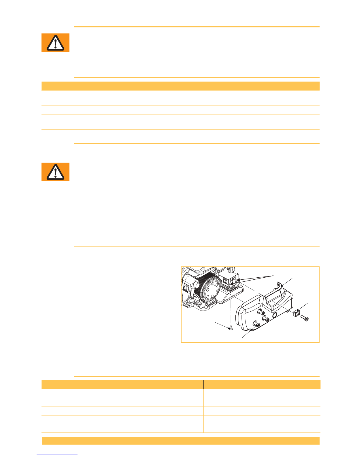
To ensure optimal stability it is recommended that the tool be re-greased regularly.
► Remove battery from tool. Remove four cylin-
der screws Torx (2), strap guide rear (3) and
side cover (4).
► Carefully spray welding device at the two
points (5) with a high-pressure-resistant
adhesive lubricating oil spray (e.g. Würth HHS
2000).
► Below at the base plate, remove counter-
sunk screw Torx (1) and also spray into the
lubrication hole with the same spray. Ret the
counter-sunk screw (1).
► Ret the side cover (4).
6.4 Cleaning/replacing the tension wheel
Required parts Order number
STB 71 / STB 73: Tension wheel (1) (wear part) 1821.047.033
STB 75: Tension wheel (1) (wear part) 1821.047.036
Ball bearing, Ø35/47x7 (2) 1930.180.356
Cylinder screw Torx, M4 (4) 1821.027.063
Wire brush (6) 1821.901.004
STB 75
1
3
4
2
5
Page 24
24 of 28
V 03.17
STRAPEX STB 71/73/75ENGLISH
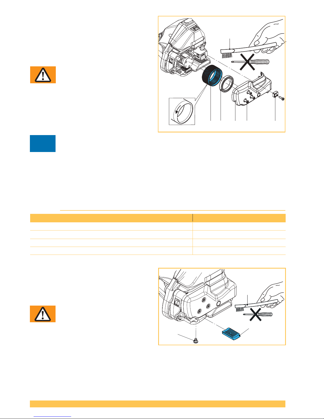
Dismantling
► Remove battery from tool. Remove four cylin-
der screws Torx (4), strap guide rear (5) and
side cover (3).
► Carefully pull out tension wheel (1).
► Remove ball bearing (2) from tension wheel.
WARNING
Wear eye protection when cleaning
with compressed air!
► Clean tension wheel (1) with compressed air.
► In the case of heavy soiling of the toothing:
Carefully clean tension wheel with enclosed
wire brush (6).
► Check tension wheel for worn teeth. If teeth
are worn, replace tension wheel.
Attention
The tension wheel must not be cleaned while it is rotating. Risk of tooth breakage!
Fitting
► Fitting is performed in reverse order. Observe the direction of rotation of the tension wheel, see
arrow.
► Lightly lubricate the inner teeth of the tension wheel with Klüber grease GBU Y 131 (Microlube).
6.5 Cleaning/replacing the tooth plate
Required parts Order number
STB 71 / STB 73: Tooth plate (2) (wear part) 1821.048.026
STB 75: Tooth plate (2) (wear part) 1821.048.030
Torx counter-sunk screw Torx (1) 1832.039.285
Wire brush (3) 1821.901.004
Dismantling
► Remove battery from tool.
► Remove counter-sunk screw Torx (1).
► Lift rocker lever towards the handle, remove
tooth plate (2).
WARNING
Wear eye protection when cleaning
with compressed air!
► Clean tooth plate (2) with compressed air.
► In the case of heavy soiling of the teeth:
Carefully clean tooth plate with enclosed wire
brush (3).
► Check tooth plate for worn teeth. If several teeth are worn, replace tooth plate.
Fitting
► Fitting is performed in reverse order. Secure counter-sunk screw (1) with Loctite 222.
– The tooth plate (2 ) must sit freely movable in the rocker.
2
1
3
!
STB 75
1 2 3 4 5
6
Page 25
25 of 28
V 03.17
STRAPEX STB 71/73/75
ENGLISH
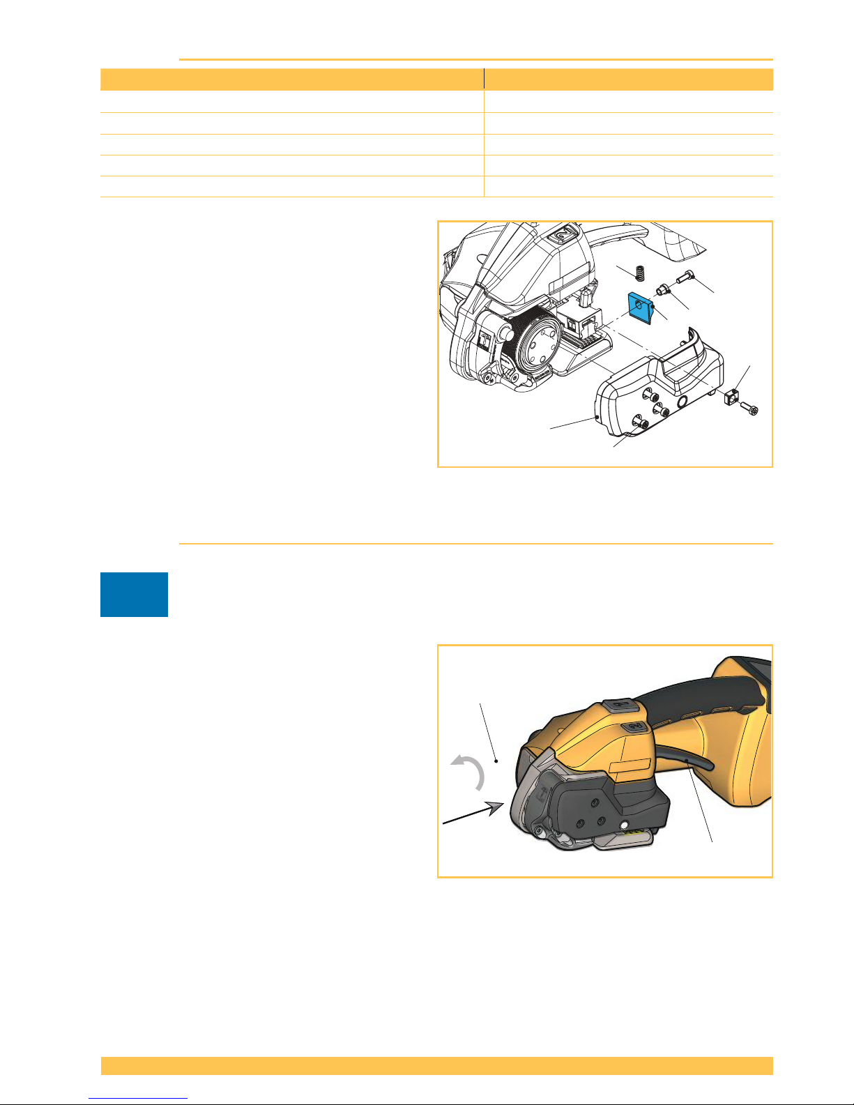
6.6 Replacing the knife
Required parts Order number
STB 71 / STB 73: Knife (1) (wear part) 1821.209.036
STB 75: Knife (1) (wear part) 1821.209.040
Cylinder screw Torx, M4 (3) 1821.027.063
Cylinder screw Torx, M4x12 (5) 1913.904.125
Flanged bushing (6) 1832.022.238
Dismantling
► Remove battery from tool.
► Remove four cylinder screws Torx (3), strap
guide rear (4) and side cover (2).
► Remove cylinder screw Torx (5) and knife (1)
with anged bushing (6). Replace knife.
Fitting
► Fitting is performed in reverse order.
► Before tting the knife (1), check whether the
pressure spring (7) above the knife is inserted.
► Secure cylinder screw (5) with Loctite 222.
6.7 Tool reset
Attention
The tool reset may only be performed if the rocker lever is blocked. Never attempt to lift
the rocker lever by force!
► Place the enclosed 3 mm hex. socket-head
key (1) through the bore hole in the base
plate directly onto the cylinder screw located
underneath (see arrow).
► Perform ten full rotations in the coun-
ter-clockwise direction. This requires a little
physical effort.
► Lift rocker lever (2).
– The welding mechanism should now pivot
upwards.
If the tool reset could not be carried out successfully, please contact the Service Centre!
!
1
2
STB 75
2
3
4
5
6
1
7
Page 26
26 of 28
V 03.17
STRAPEX STB 71/73/75ENGLISH
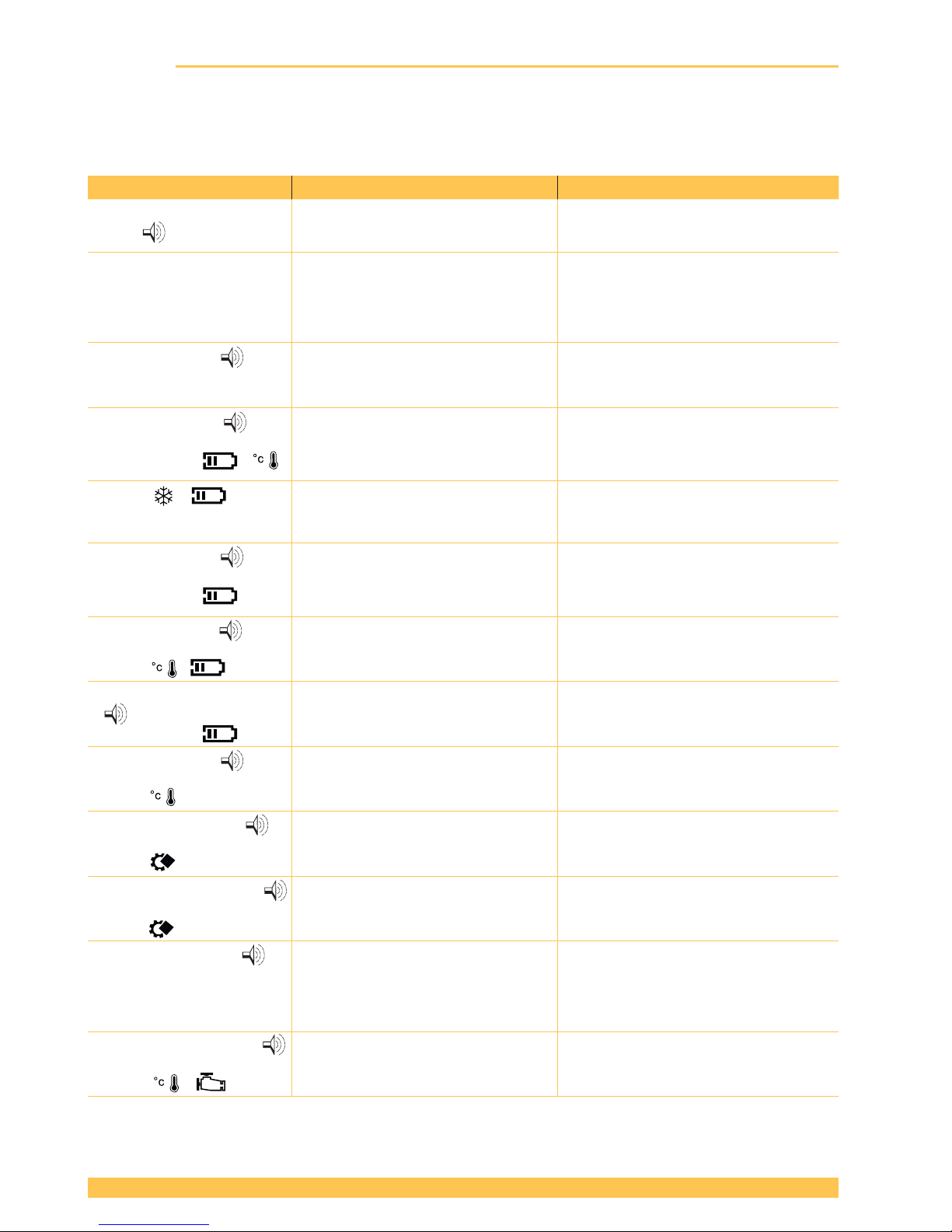
6.8 Troubleshooting
If certain errors occur, the background lighting of the operating panel and the fault display (symbol +
code) illuminate, and an acoustic signal sounds.
If the error is still pending (is not reset automatically), acknowledge by removing / inserting the battery.
Display / state Probable cause Remedy / Corrective action
Operating panel does not
react +
● Button lock is switched on. ► Switch off button lock: see Section
4.6.
Display remains dark. ● Battery faulty / fully discharged.
● Battery not properly inserted.
► Charge/replace battery.
► Check whether battery is complete-
ly inserted and unlocking device
engaged.
E11, red display +
pulsating (long)
Symbol ashes
● Inserted battery not permitted
(wrong battery).
► Insert correct battery.
E20, red display +
pulsating (long)
Symbol ashes &
● Battery too hot (> 60°C/140°F). ► Allow battery to cool.
► Charge battery, replace if neces-
sary.
Symbols & ashing ● Battery temperature too low. ► At a higher battery temperature
it recovers by itself. Work possible.
Max. strap tension is not reached.
E24, red display +
pulsating (long)
Symbol ashes
● Battery not properly inserted.
● Wrong battery.
► Insert battery properly.
► Charge battery, replace if neces-
sary.
E25, red display +
pulsating (long).
Symbols & ashing
● Battery not properly inserted.
● Temperature sensor faulty.
► Insert battery properly.
► Replace if necessary.
E27 (E23), red display
+ pulsating (long)
Symbol ashes
● Battery undervoltage limits
reached.
● Battery empty.
► Charge battery, replace if neces-
sary.
E33, red display +
pulsating (long)
Symbol
● Electronics overtemperature.
● Controller too hot.
► Allow tool to cool.
E37, orange display +
pulsating (medium)
Symbol
● Tool jams during welding pro-
cess, dirty welding mechanism or
foreign body in tool.
► Clean welding mechanism.
E50/51 orange display +
pulsating (medium)
Symbol
● Aborting of welding or cooling
process by lifting the rocker lever.
► Repeat strapping.
E57 orange display +
pulsating (medium)
Tension force display
ashes.
● Strap slipped or broken. ► Reinsert strap.
► Check: Tension force, dirty strap,
right strap and state of tension
wheel / tooth plate.
E55/56 orange display +
pulsating (medium)
Symbols &
● Aborting of tensioning process.
● Performance limitation or time
out.
► Repeat tensioning.
In the case of other error numbers not described here, please contact the the local service center.
If the error cannot be rectied by applying the measures described above, please contact the local
service center!
Page 27

27 of 28
V 03.17
STRAPEX STB 71/73/75
ENGLISH
7 Technical data
STB 71 STB 73 STB 75
Weight 3.6 kg (7.9 lb) 3.8 kg (8.4 lb) 4.3 kg (9.5 lb)
(incl. battery) (incl. battery) (incl. battery)
Dimensions Length 370 mm/14.5” Length 370 mm/14.5” Length 370 mm/14.5”
Width 141 mm/5.5” Width 141 mm/5.5” Width 143 mm/5.6”
Height 135 mm/5.3” Height 135 mm/5.3” Height 135 mm/5.3”
Strap tension 400–1200 N 900–2500 N 1300–4500 N
(90–270 lbf) (200–560 lbf) (290–1000 lbf)
Soft: 150–750 N Soft: 400–1360 N Soft: 400–1600 N
(22–165 lbf) 90–305 lbf) 90–340 lbf)
Tension speed 0–290 mm/s (11.3 in/s) 0–220 mm/s (8.6 in/s) 0–120 mm/s (4.7 in/s)
Sealing Friction weld Friction weld Friction weld
Typical measured A-rated
emission sound pressure
level
– EN ISO 11202 LpA 79 dB (A) L
pA
78 dB (A) L
pA
79 dB (A)
– EN 60745-1/2:2009 L
pAeq
77 dB (A) L
pAeq
82 dB (A) L
pAeq
81 dB (A)
Average sound power level
– EN 60745-1/2:2009 LW
Aeq
88 dB (A) LW
Aeq
93 dB (A) LW
Aeq
92 dB (A)
Deviation K 3.0 dB (A) 3.0 dB (A) 3.0 dB (A)
Vibrations at handle*
– EN 60745-1/2:2009 ah 2.4 m/s
2
ah 2.4 m/s
2
ah 2.3 m/s
2
Deviation K 1.5 m/s
2
1.5 m/s
2
1.5 m/s
2
Operating temperature for
the strapping tool –10 °C to +40 °C –10 °C to +40 °C –10 °C to +40 °C
(See separate operating (14–104 °F) (14–104 °F) (14–104 °F)
instructions for battery and
charging device)
Relative humidity Up to 90 % Up to 90 % Up to 90 %
CHARGER / BATTERY
Rated voltage charger 100 / 110 / 230 V 100 / 110 / 230 V 100 / 110 / 230 V
Charger type BOSCH GAL 1880 CV BOSCH GAL 1880 CV BOSCH GAL 1880 CV
Charging time 15–30 minutes, after 15–30 minutes, after 25–35 minutes, after
15 min. approx. 80% 15 min. approx. 80% 25 min. approx. 80%
charging capacity charging capacity charging capacity
Strappings with one 400–800 depending 200–800 depending 300–800 depending
battery charge on strap, strap tension on strap, strap tension on strap, strap tension
and package and package and package
Battery 18 V/2.0 Ah, Li-Ion 18 V/2.0 Ah, Li-Ion 18 V/4.0 Ah, Li-Ion
BOSCH BOSCH BOSCH
* refer to Section 2.3, Vibration exposure
Continued on the next page
Page 28

28 of 28
V 03.17
STRAPEX STB 71/73/75ENGLISH
Continuation:
STB 71 STB 73 STB 75
PLASTIC STRAP
Strap type Polyester (PET) Polyester (PET) Polyester (PET)
Polypropylene (PP) Polypropylene (PP) Polypropylene (PP)
Strap width adjustable to 9–10, 12–13 mm 12–13, 15–16 mm 15–16, 18–19 mm
(
3
/
8
″,
1
/
2
″) (
1
/
2
″,
5
/
8
″) (
5
/
8
″,
3
/
4
″)
Strap thickness 0.40–0.80 mm (PET) 0.5–1.0 mm 0.8–1.3 mm
(.015″–.031″) (.019″–.040″)
(.031″–.051″)
0.50–0.80 mm (PP)
(.019″–.031″)
8 EC Declaration of Conformity (copy)
(CE 2006/42/EC, Annex II 1.A.)
The manufacturer take sole responsibility for declaring that the machines to which this declaration
refers are in full conformity with the current requirements of the Council Directive of 17th May 2006
(2006/42/EC) "Machine Directive" and its amendments.
Furthermore, electrical installations are in conformity with the requirements of the Council Directive of
26th February 2014 (2014/30/EU) "EMC Directive".
The following harmonised standards
were taken into account: EN 60745-1:2009 + A11:2010; EN 60745-2-18:2009; EN ISO
12100:2011; EN 349:2008; EN 61000-6-1; EN 61000-6-3
EEC-Design certication: No. M8A 17 03 28456 006
Place of certication: TÜV SÜD Product Service GmbH
Type designations: STB 71, STB 73, STB 75
From machine no./ year of construction: A/17020001, B/17020001, C/17020001 / 2017
CH-8953 Dietikon, 14.02.2017
Orgapack Orgapack
Packaging Technology: Packaging Technology:
U. Schweizer M. Binder
General Manager Director Development / Standard Products
Agent for the publication of technical documentation:
Signode Industrial Group GmbH, ORGAPACK Packaging Technology, Silbernstrasse 14,
8953 Dietikon 1, Switzerland
Manufacturer
Strapex Silbernstrasse 14
c/o Signode Industrial Group GmbH Postfach 595
Orgapack Packaging Technology 8953 Dietikon 1, SWITZERLAND
www.sigpse.com
 Loading...