

Page 1
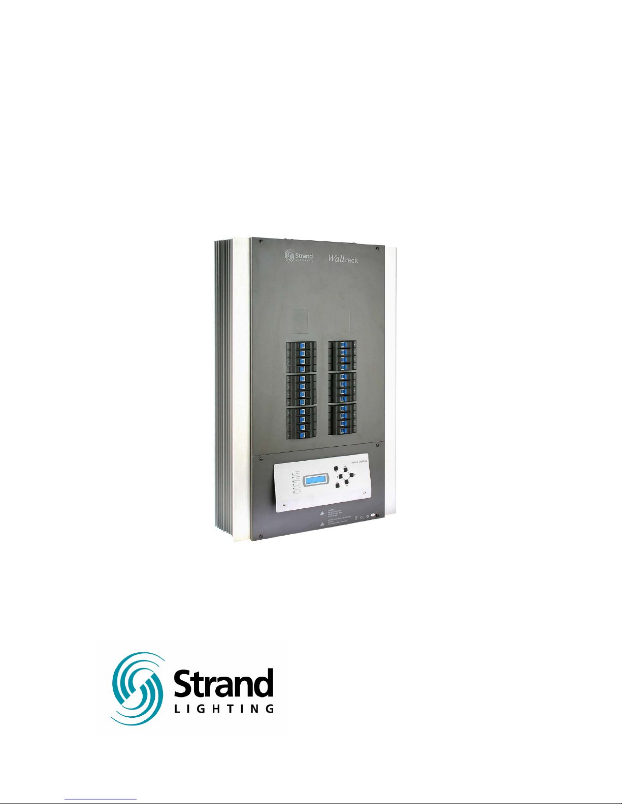
Wallrack User’s Manual
Part Number 24-004-1837
Revision Level 1.2
Revision Date March 2006
Page 2

Offices and Service Centres
Strand Lighting Limited, Mitchelston Industrial Estate, Kirkcaldy, Fife, KY1 3LY United Kingdom
Tel: +44 (0)1592 656400 Fax: +44 (0)1592 653528
Strand Lighting Limited, Unit 3, Hammersmith Studios, Yeldham Road, London, W6 8JF United
Kingdom
Tel: +44 (0)20 8735 9790 Fax: +44 (0)20 8735 9799
Strand Lighting Italia srl, Via delle Gardenie 33, 00040 Pomezia-Roma, Italy
Tel: +39 06 919631 Fax: +39 06 9147136
Strand Lighting GmbH, Kurfürstendamm 70, 10709 Berlin, Germany
Tel: +49 30 707 9510 Fax: +49 30 707 95199
Strand Lighting Asia, 20/F Delta House, 3 On Yiu Street, Shatin, N.T. Hong Kong
Tel: + 852 2757 3033 Fax: + 852 2757 1767
Strand Lighting Inc, 6603 Darin Way, Cypress, CA 90630, USA
Tel: +1 714 230 8200 Fax: +1 714 230 8173
Strand Lighting (Canada) Inc, Eclairages Strand (Canada) Inc., 2430 Lucknow Drive #15,
Mississauga, Ontario , L5S 1V3, Canada
Tel: +1 905 677 7130 Fax: +1 905 677 6859
The material in this manual is for information purposes only and is subject to change without notice.
Strand Lighting assumes no responsibility for any errors or omissions which may appear in this
manual. For comments and suggestions regarding corrections and/or updates to this manual, please
contact your nearest Strand Lighting office.
El contenido de este manual es solamente para información y está sujeto a cambios sin previo aviso.
Strand Lighting no asume responsabilidad por errores o omisiones que puedan aparecer. Cualquier
comentario, sugerencia o corrección con respecto a este manual, favor de dirijirlo a la oficina de
Strand Lighting más cercana.
Der Inhalt dieses Handbuches ist nur für Informationszwecke gedacht, Aenderungen sind vorbehalten.
Strand Lighting uebernimmt keine Verantwortung für Fehler oder Irrtuemer, die in diesem Handbuch
auftreten. Für Bemerkungen und Verbesserungsvorschlaege oder Vorschlaege in Bezug auf
Korrekturen und/oder Aktualisierungen in diesem Handbuch, moechten wir Sie bitten, Kontakt mit der
naechsten Strand Lighting-Niederlassung aufzunehmen.
Le matériel décrit dans ce manuel est pour information seulement et est sujet à changements sans
préavis. La compagnie Strand Lighting n'assume aucune responsibilité sur toute erreur ou ommission
inscrite dans ce manuel. Pour tous commentaires ou suggestions concernant des corrections et/ou
les mises à jour de ce manuel, veuillez s'll vous plait contacter le bureau de Strand Lighting le plus
proche.
Information contained in this document may not be duplicated in full or in part by any person without
prior written approval of Strand Lighting. Its sole purpose is to provide the user with detailed
operational information for the equipment supplied. The use of this document for all other purposes is
specifically prohibited. Certain features of the equipment described in this document may form the
subject of patents or patent applications.
Manual and Software Copyright © March, 2006, Strand Lighting Limited. All rights reserved.
Page 3

General Information
This equipment operates at voltage levels that are potentially lethal. Do not
touch any of the internal parts of the equipment unless you are fully aware
of the hazards involved and the precautions to be taken.
It is imperative to provide an adequate earth conductor for the rack and
load connections. Do not rely on earthing via conduit or trunking.
The equipment described in this manual is designed and manufactured to comply
with international safety standards IEC 950 and is intended for use as part of a
lighting control system. It must not be used for other purposes where there is any
risk of safety to persons. It is important that installation be carried out in
accordance with the instructions given in this manual and in compliance with
applicable electrical regulations. The work should be carried out by a suitably
qualified electrician.
The system is designed to be permanently installed with supply and load wiring
permanently connected.
In the interests of continued safe and reliable operation, observe the following
guidelines:
• Keep the equipment at a room temperature of 0-35°C and a relative humidity
of 10-95% (non-condensing) during operation. For operation between 35°C and
40°C de-rate the maximum load by 4% per °C.
Do not, under any circumstances, operate the equipment above 40°C or in an
environment that may become wet.
• Avoid sudden extremes of temperature, rain, direct sunlight, or other heat
sources.
• Make sure that wires and cables are routed sensibly and wired in
accordance with local regulations.
• DO NOT drop the equipment or subject it to excessive bumping or jarring.
• DO protect the unit from excessive dust or other contamination.
Page 4

Wallrack User Manual
Table of Contents
Installation............................................................................................ 5
Location ................................................................................ 5
Ventilation.............................................................................5
Weight...................................................................................5
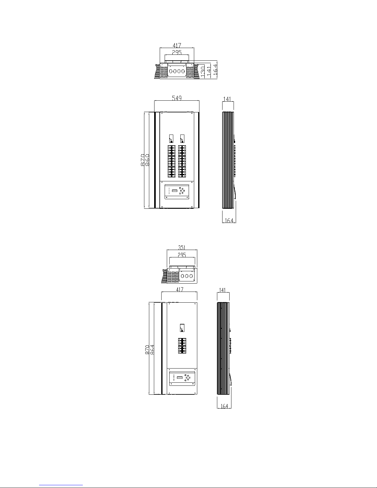
Dimensions...........................................................................5
Installation Procedure ........................................................... 7
Supply Connections..............................................................7
Three Phase.....................................................................7
Single Phase..................................................................... 8
Load Connections.................................................................8
RCD Option......................................................................... 10
Control Signal Connections................................................. 12
Processor set up................................................................................13
Main Menu..........................................................................13
Set Level............................................................................. 14
Preset..................................................................................15
Address...............................................................................16
Curve .................................................................................. 17
Set minimum level............................................................... 18
Set maximum level.............................................................. 19
Set up menu........................................................................ 20
Response Time............................................................... 20
DMX Port........................................................................21
DMX Fail......................................................................... 22
Set Signal Call................................................................23
Version Number..............................................................23
Set Factory Defaults.......................................................23
Triac Replacement............................................................................. 24
User Manual v1.2 March 2006 4
Page 5

Wallrack User Manual
Installation
Dimmer systems contain potentially hazardous voltages and high temperatures.
Installation should only be carried out by suitably qualified personnel, safe working
practices observed, and caution exercised at all times. Ensure that all Power supplies
are properly isolated before gaining access
Location
Any dimmer installation requires careful choice of location. Dimmers
should, if possible, be sited close to the lamp loads to minimise cable runs.
Although the design of
Wallrack reduces the radiated noise common to
conventional dimmers, it is important to avoid siting in acoustically `live'
positions in the performance area.
The incoming mains distribution should be sited as close to the racks as
practicable, and adequately fused isolators provided close to each rack.
Max rating 80A-3 phase, 160A-single phase.
Allow adequate clearance at the front of the dimmer rack, in order for it to
be opened for wiring to the load, supply and control terminals and allow
safe servicing of the equipment.
Ventilation
Adequate ventilation must be provided to maintain an ambient
temperature within the range 0 to 35°C and humidity of 45-95% noncondensing. Special attention should be paid to the need to maintain
ambient temperature within these limits when
Wallrack is enclosed in a
small room.
Do not obstruct the ventilation slots.
Weight
24 x 2.5kW 6 x 5kW
Wallrack: 43kg 31.4kg
Wallrack, packed: 49kg 34.5kg
Wallrack dimmers are heavy, take care when lifting
Dimensions
Cable entry dimensions are as follows:
•
Power Wiring Top 4 x 25mm holes suitable for conduit.
•
Control Wiring Bottom 4 x 25mm holes suitable for conduit.
User Manual v1.2 March 2006 5
Page 6
Wallrack User Manual
Wallrack 24 x 2.5kW
Wallrack 6 x 5kW
User Manual v1.2 March 2006 6
Page 7
Wallrack User Manual
Installation Procedure
After unpacking the rack, remove the front panel (6 screws) and the Earth
leads attached to it.
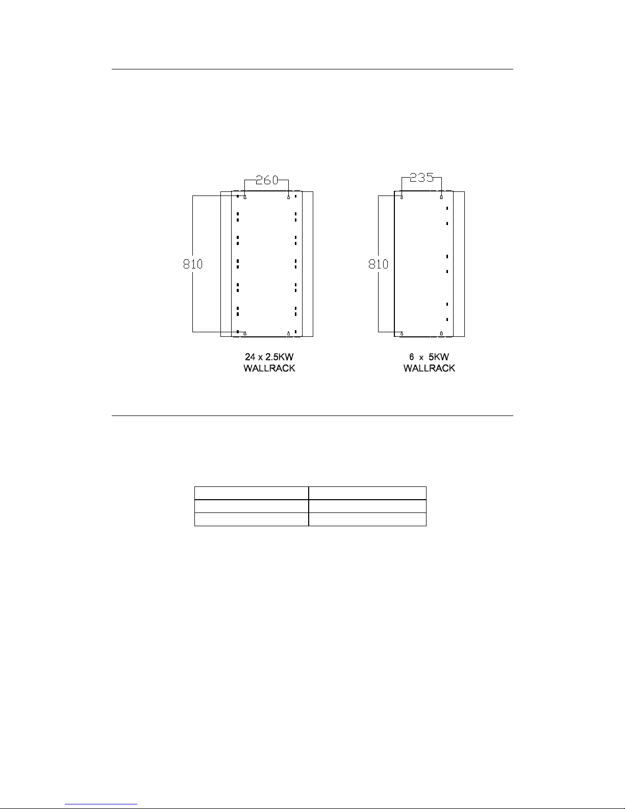
The rack(s) should be secured to the wall before installation
•
Power wiri ng: Top
•
Control wiring: Bottom
Supply Connections
Wallrack s are equipped with terminals for Single or Three phase plus
Neutral and Earth connections.
24x2.5kW Wallrack 6x5kW Wallrack
Single Phase: 120A Single Phase: 150A
Three Phase: 90A Three Phase: 50A
For single phase, there will be an optional single phase kit. The terminals
are provided for (2.5kW dimmers are 25 mm
2
, 5kW dimmers are 32mm2)
wires of the NEUTRAL and PHASE terminals.
Three Phase
Conductor sizes must be chosen to comply with local regulations and are
usually calculated to take into consideration cable lengths and types.
Typically, wiring for 3 PHASE LIVE conductors should be 25mm
2
for
2.5kW dimmers and 32mm
2
for 5kW dimmers maximum rack load
capacity.
User Manual v1.2 March 2006 7
Page 8
Wallrack User Manual
For the NEUTRAL conductor, we recommend a size of at least 2 x phase
conductor size to allow for the harmonic currents generated by phase
control dimmers.
Single Phase
Typically wiring for both LIVE L1 and NEUTRAL N should be 25mm
2
for
2.5kW dimmers and 32mm
2
for 5kW dimmers for maximum rack load
capacity. For this application use the Single Phase strapping kit. If single
phase current is higher than the size of the cable, additional Live and
Neutral wires are recommended to share the current flows.
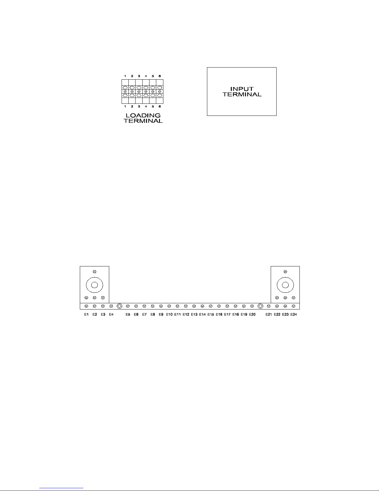
Load Connections
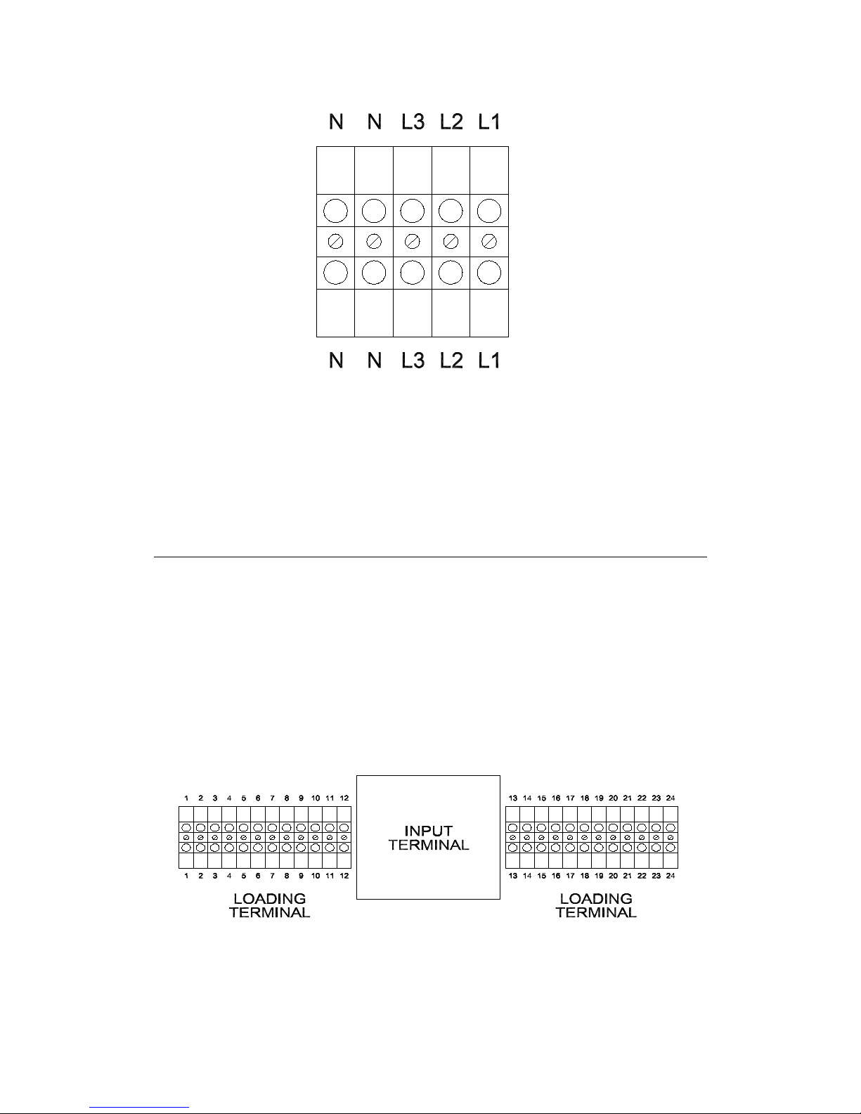
Connections for both LIVE and NEUTRAL are supplied at each dim m er
output to allow two loads to be connected in parallel without the need to fit
two wires in a single terminal. The terminals are located on the Power
Blocks. Please refer to the Power Block Termination details in the
appendix.
Load terminals allow for 2.5kW dimmers up to 4mm
2
stranded direct into
the terminals
Wallrack 24 x 2.5kW
User Manual v1.2 March 2006 8
Page 9
Wallrack User Manual
Wall
rack
6 x 5kW
Earth connections are made directly to the Earth Busbar. 24 busbar
clamps for up to 4mm
2
wires are provided in the installation kit and are
fitted as required.
User Manual v1.2 March 2006 9
Page 10
Wallrack User Manual
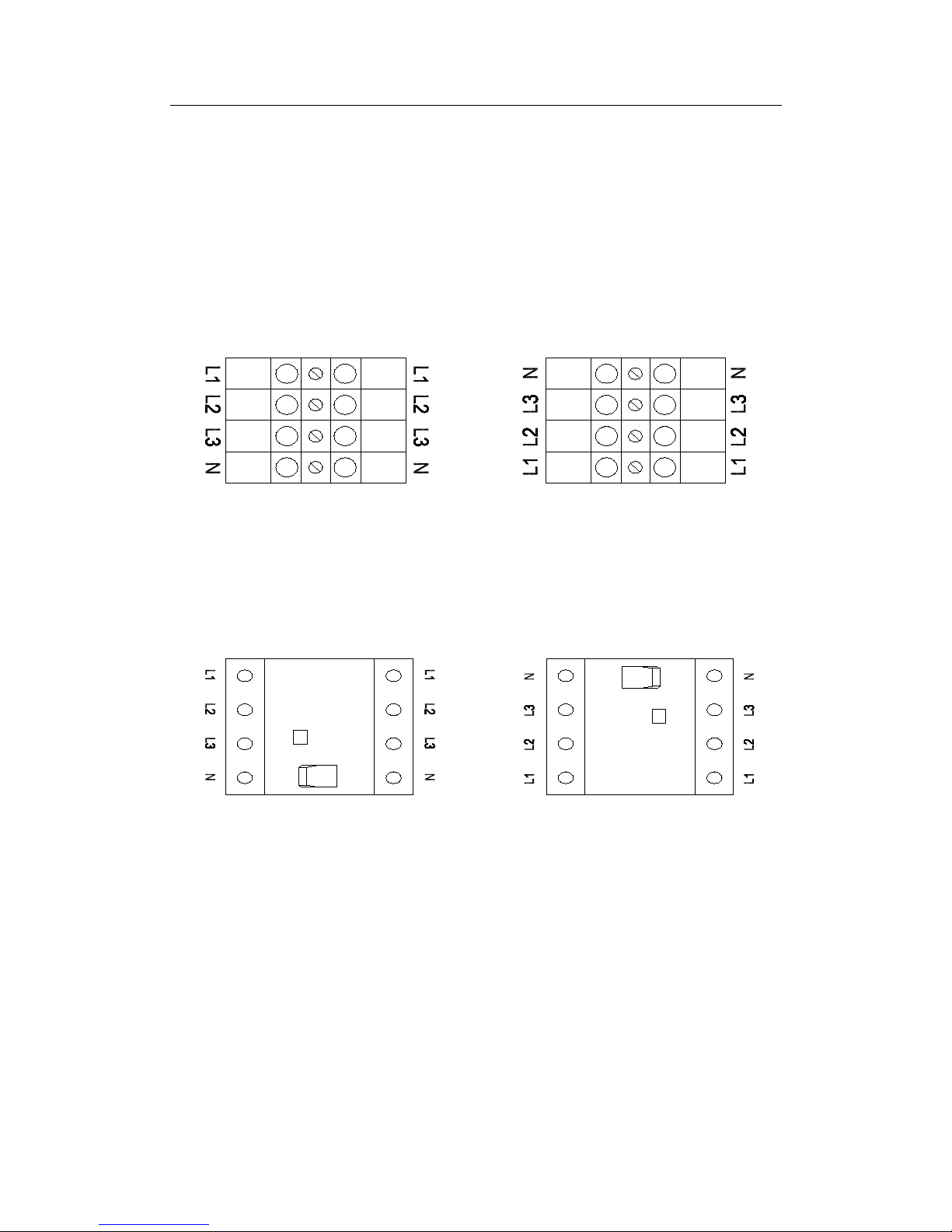
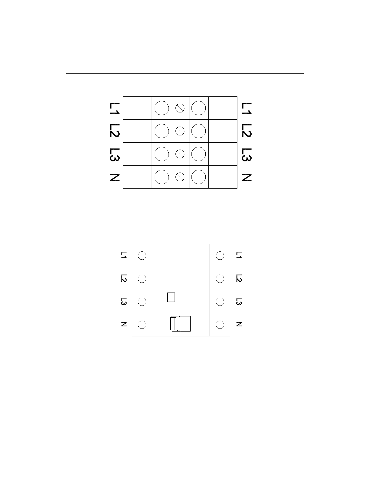
RCD Option
Wallrack is designed to house two 3 phase RCD (optional) if required.
This option only applies when using a 3 phase supply to the dimmer rack
it cannot be used on single phase racks.
To install the RCD, simply remove the terminals as shown:
Wallrack 24 x 2.5kW
And replace with the RCDs. Reconnect the power cables as shown below.
User Manual v1.2 March 2006 10
Page 11
Wallrack User Manual
Wallrack 6 x 5kW
And replace with the RCDs. Reconnect the power cables as shown below.
User Manual v1.2 March 2006 11
Page 12
Wallrack User Manual
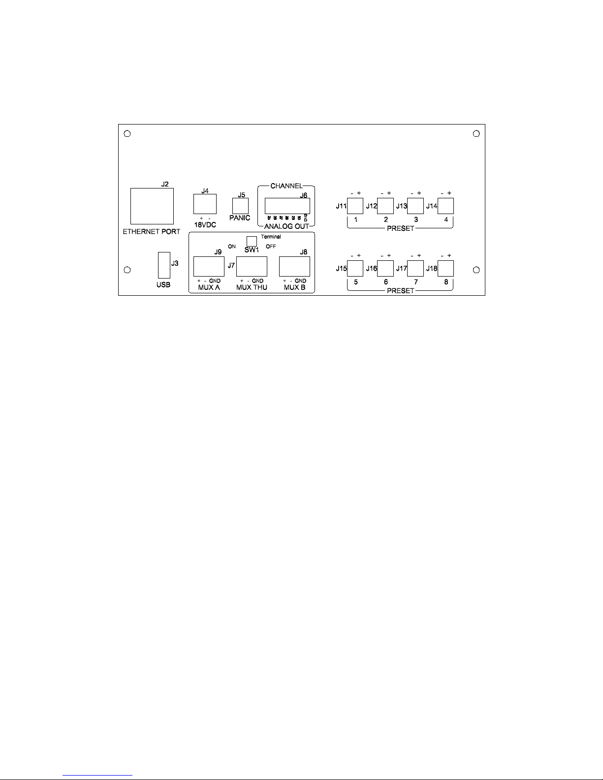
Control Signal Connections
Control connections are made via screw terminals on the plug-in
connectors fitted to the Processor Unit PCB
J2 & J3 : Not used.
J4: 18VDC for Architectural control panels.
J5: Remote panic connection.
J6: Analogue output 0-10V control signals to drive external devices.
J7: DMX THRU output.
J8: DMX B input.
J9: DMX A input.
J11-J18: Preset 1-8 contact.
SW1-1: Termination for Mux B
SW1-2: Termination for Mud A
User Manual v1.2 March 2006 12
Page 13
Wallrack User Manual
Processor set up
The
Wallrack offers a selection of set up and configuration features.
These are accessed from the front panel using the six set up keys and
LED Display. Menu and setting selections are made with the Up/Down
and/or Left/Right keys. To exit any menu press the ESC escape key. OK
is the confirmation key.
Main Menu
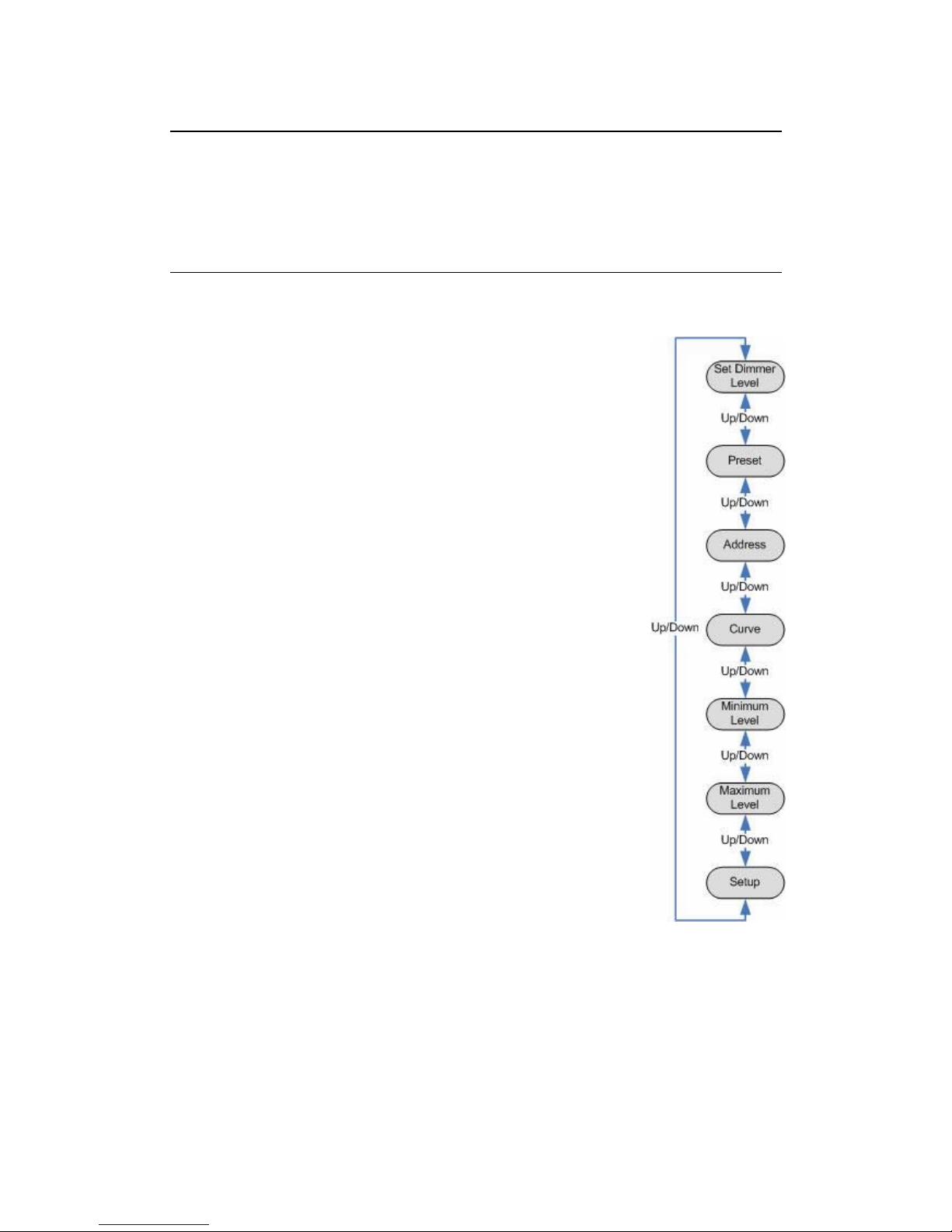
Normal display will show
Wallrack. Press Up/Down
key to select:
Set Dimmer Level (SET_L_)
Preset (PRESET)
Address (PATCH_)
Curve (CURVE_)
Minimum Level (MIN_L_)
Maximum Level (MAX_L_)
Set up (SETUP_)
Press Right button to enter into any of that specific
menu. OK to confirm changes and Esc to exit
without any changes.
Keylock function: Lock configuration by holding
[ESC] and [OK] for 3 seconds (5th digit dot is ON).
Repeat to unlock.
User Manual v1.2 March 2006 13
Page 14
Wallrack User Manual
Set Level
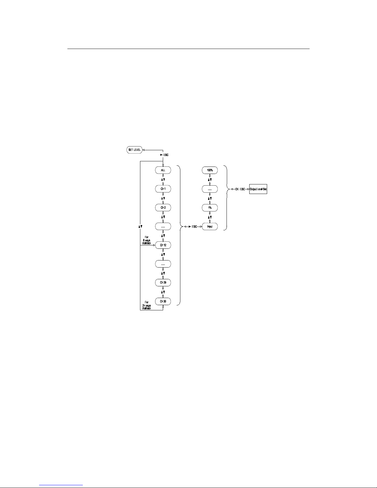
Press Down button once to go to Set Level menu. Press Right button to
enter.
Use Up/Down buttons to select all or channels (24 ways: 1- 30, 6 ways: 1-
12). Press the Right button to set the level.
Use Up/Down buttons to select Input or an output level of 0-100%. Use
the Right button to set the level. Repeat as necessary to set other
channels.
Press OK to confirm changes, press OK again to save or press Esc to exit
without saving any changes.
User Manual v1.2 March 2006 14
Page 15
Wallrack User Manual
Preset
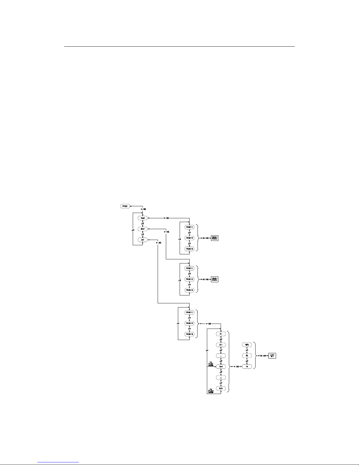
Press Down button twice to go to the Preset menu, press Right button to
enter.
Use Up/Down buttons to select either Recall, Snap shot or Edit. Use the
Right button to enter.
For Recall, press Right button to enter. Use Up/Down to select Preset
number 1-8, press OK to confirm changes or press Esc to exit without
saving any changes.
For Snap shot, press Right button to enter. Use Up/Down to select Preset
number 1-8, press OK to snap shot the DMX level or press Esc to exit
without saving any changes.
For Edit press, press Right button to enter. Use Up/Down to select Preset
number 1-8, press Right button to enter.
Use Up/Down buttons to select Input or an output level of 0-100%. Use
the Right button to set the level. Repeat as necessary to set other
channels.
Press OK to confirm changes, press OK again to save or press Esc to exit
without saving any changes.
User Manual v1.2 March 2006 15
Page 16
Wallrack User Manual
Address
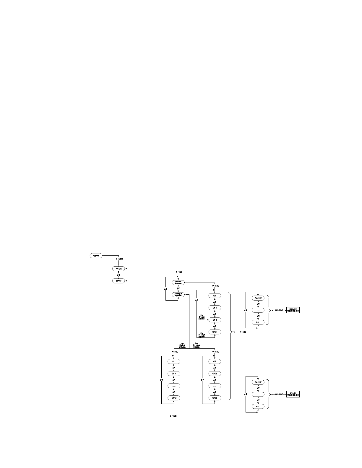
Press Down button three times to get to the Address menu. Press Right
button to enter.
Use Up/Down buttons to select either the Start Address or Patch. Press
Right button to enter.
For Patch, use Up/Down buttons to select either Mux Patch or Analogue
Patch. Press Right button to enter.
The Mux Patch allows you to patch dimmers (24 ways: 1- 24, 6 ways: 1-6).
Use the Up/Down buttons to select ALL or individual dimmers. Press
Right button to enter. Use Up/Down to select DMX Address 1- 512.
Repeat as necessary to set the address on other dimmers.
Press OK to confirm changes, press ag ain to save or press Esc to exit
without saving any changes.
The Analogue Patch allows you to patch 0-10v analogue outputs (24
ways: 25- 30, 6 ways: 7-12). Use the Up/Down buttons to select ALL or
individual outputs. Press Right button to enter. Use Up/Down to select
DMX Address 1- 512. Repeat as necessary to set the address on other
analogue outputs.
Press OK to confirm changes, press ag ain to save or press Esc to exit
without saving any changes.
For Start Address, use Up/Down buttons to select the start DMX address
of 1-512.
Press OK to confirm changes, press ag ain to save or press Esc to exit
without saving any changes.
.
User Manual v1.2 March 2006 16
Page 17
Wallrack User Manual
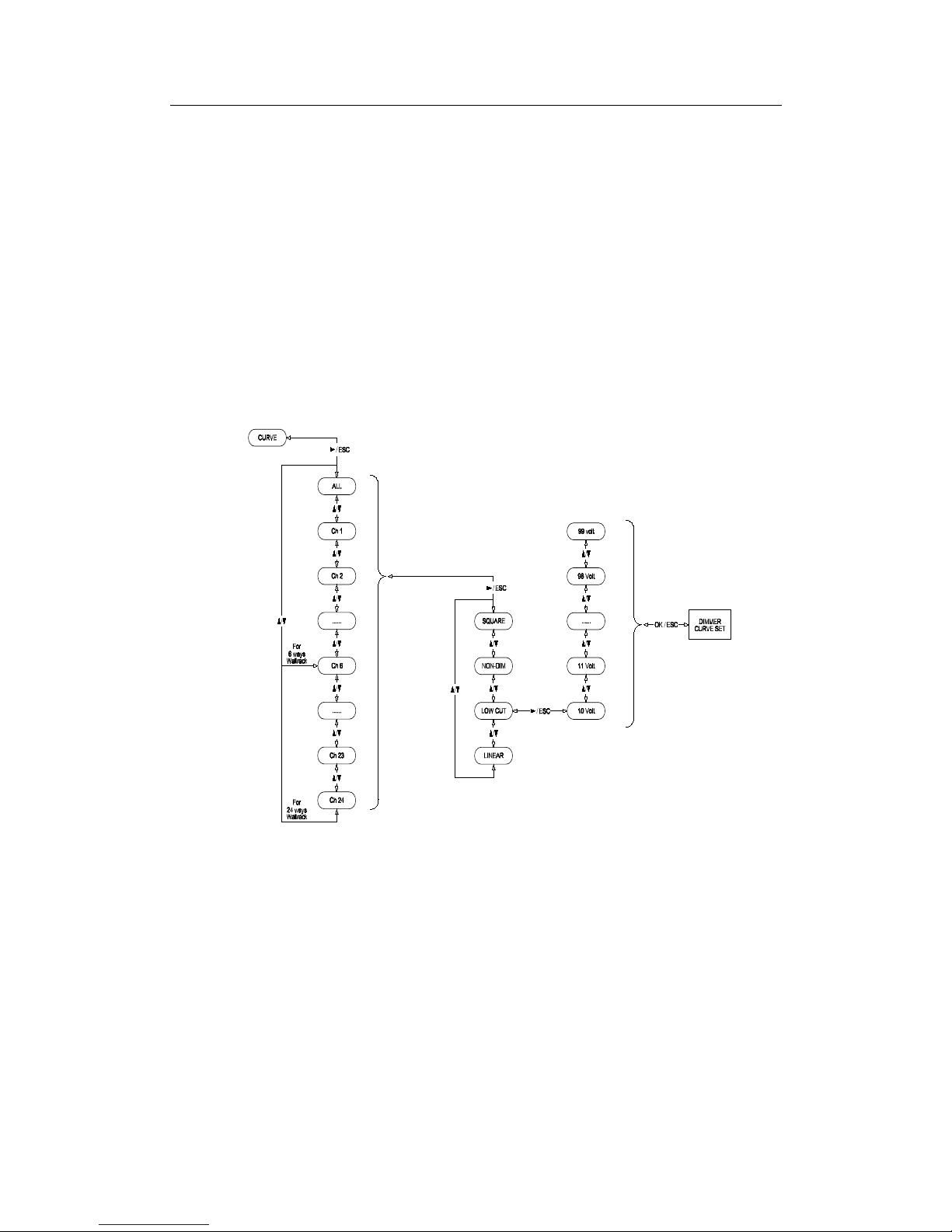
Curve
Press Down button four times to go to Curve menu. Press Right button to
enter.
Use Up/Down buttons to select all or channels (24 ways: 1- 24, 6 ways: 1-
6). Press the Right button to set the curve.
Use Up/Down buttons to select Square, Nondim, Lowcut or Linear. Use
the Right button to enter. Repeat as necessary to set other channels.
For Lowcut, use Up/Down buttons to select the lowcut level between 10 –
90 volt. Use the Right button to enter.
Repeat as necessary to set other channels. Press OK to confirm changes,
press OK again to save or press Esc to exit without saving any changes.
User Manual v1.2 March 2006 17
Page 18
Wallrack User Manual
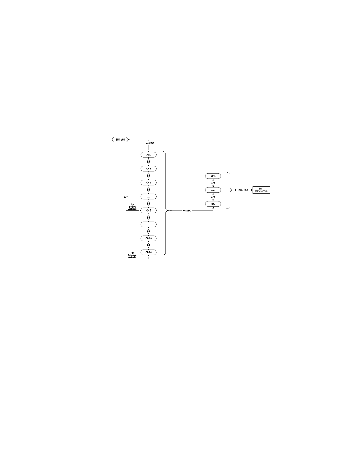
Set minimum level
Press Down button five times to go to Minimum Level menu. Press Right
button to enter.
Use Up/Down buttons to select all or channels (24 ways: 1- 24, 6 ways: 1-
6). Press the Right button to set the level.
Use Up/Down buttons to select a minimum level between 0 - 30. Use the
Right button to enter. Repeat as necessary to set other channels.
Press OK to confirm changes, press OK again to save or press Esc to exit
without saving any changes.
User Manual v1.2 March 2006 18
Page 19
Wallrack User Manual
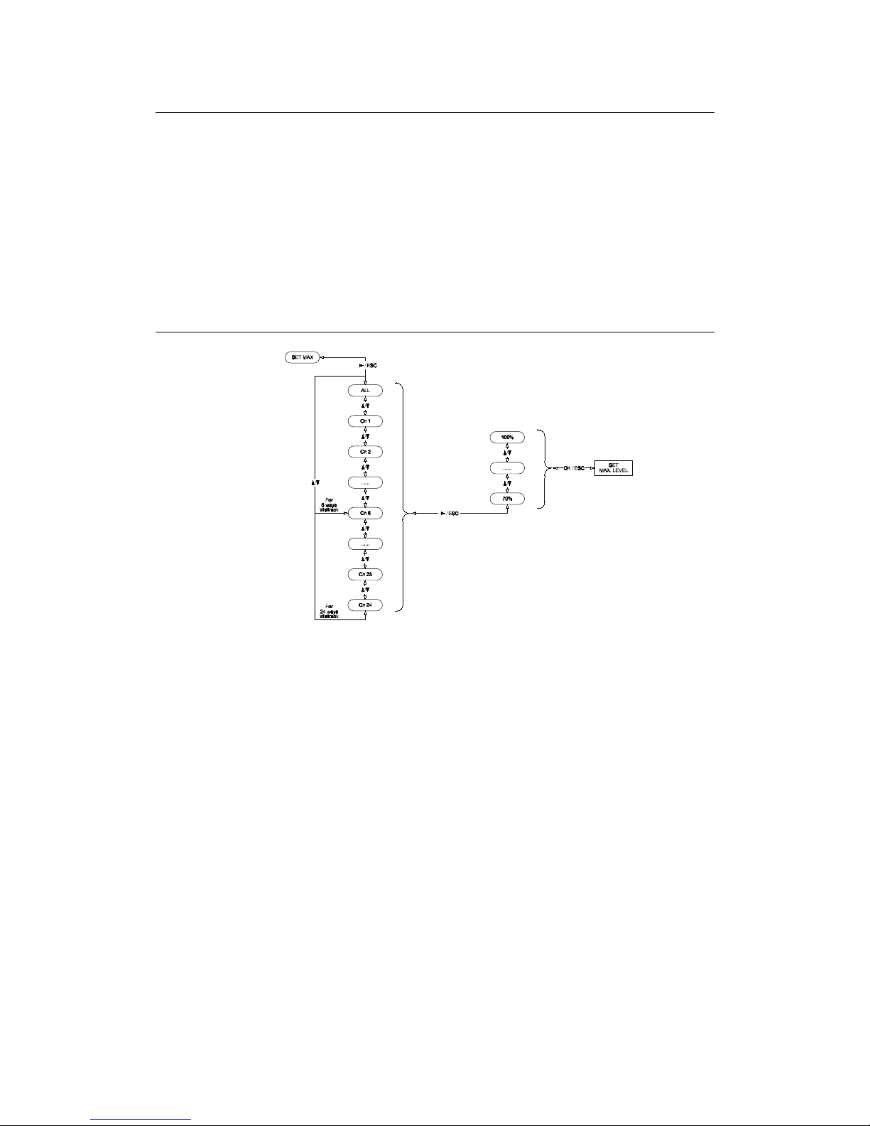
Set maximum level
Press Down button six times to go to Maximum Level menu. Press Right
button to enter.
Use Up/Down buttons to select all or channels (24 ways: 1- 24, 6 ways: 1-
6). Press the Right button to set the level.
Use Up/Down buttons to select a maximum level between 70 - 100. Use
the Right button to enter. Repeat as necessary to set other channels.
Press OK to confirm changes, press OK again to save or press Esc to exit
without saving any changes.
User Manual v1.2 March 2006 19
Page 20
Wallrack User Manual
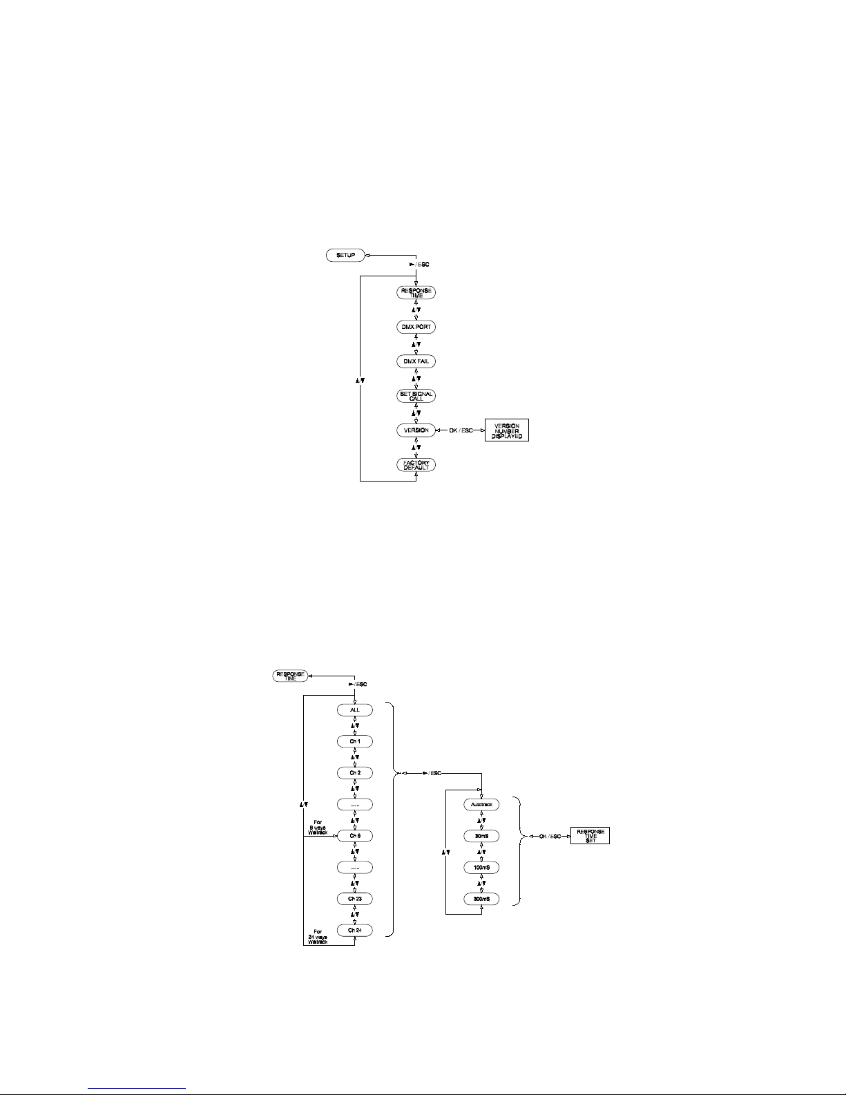
Set up menu
Press Down button seven times to go to the Set Up menu. Press Right
button to enter.
Use Up/Down buttons to select either Response time, DMX port, DMX fail,
Set Signal Call, Display Version or Set Factory default. Press Right button
to enter.
Response Time
For Response time, use Up/Down buttons to select ALL or channels (24
ways: 1- 24, 6 ways: 1-6). Press Right button to enter.
Use Up/Down buttons to select either Autotrack, 30mS, 100mS or 300mS.
Press Right button to enter. Repeat as necessary for other channels.
Press OK to confirm changes, press ag ain to save or press Esc to exit
without saving any changes.
User Manual v1.2 March 2006 20
Page 21
Wallrack User Manual
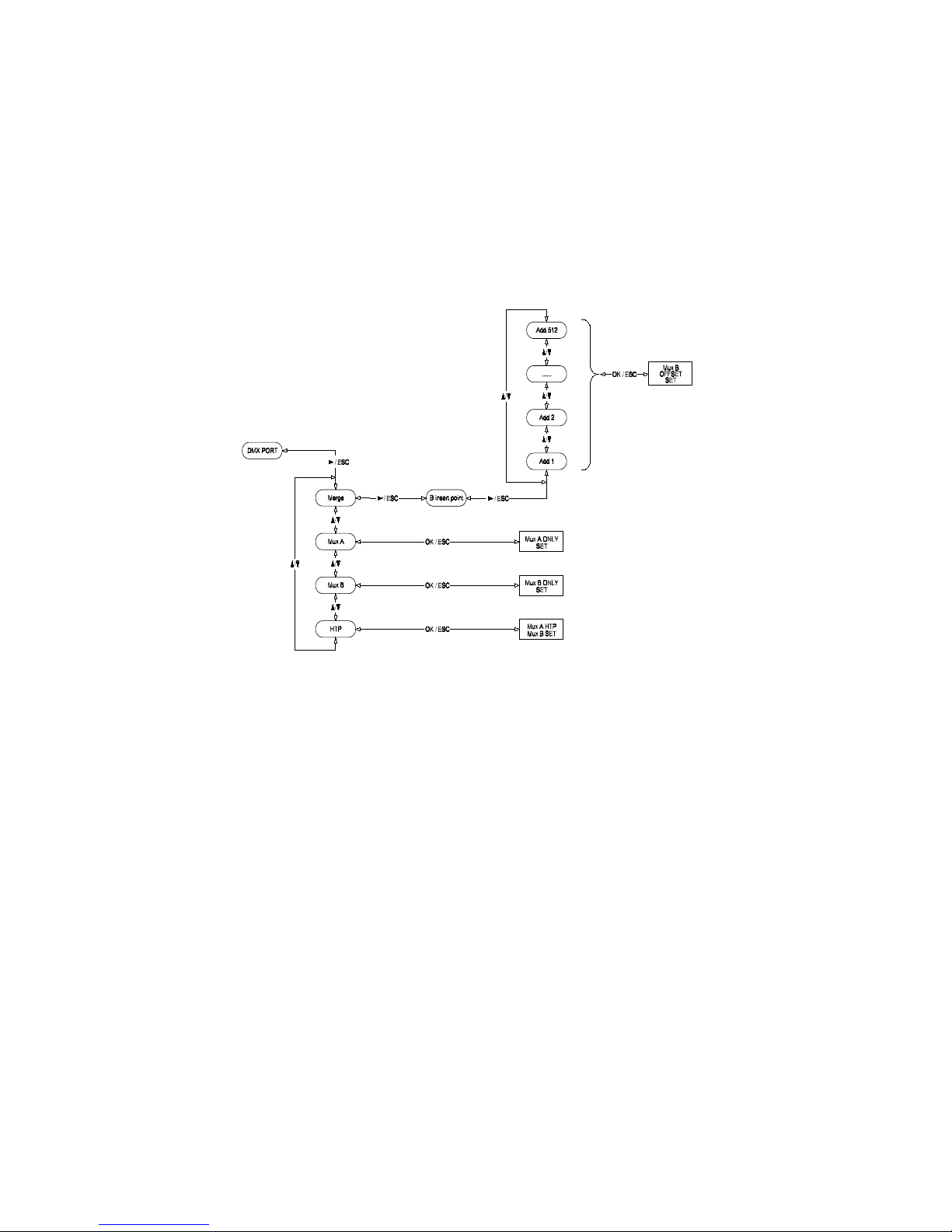
DMX Port
For DMX port, use Up/Down buttons to select either Merge, Mux A, Mux
B or HTP. Press Right button to enter.
For the Merge option, you will also need to select the point that Mux B
merges with Mux A. Press the Right button and then use the Up/Down
buttons to select the first Mux B address to merge with DMX 1 of Mux A.
Press Right button to enter.
Press OK to confirm changes, press ag ain to save or press Esc to exit
without saving any changes.
User Manual v1.2 March 2006 21
Page 22
Wallrack User Manual
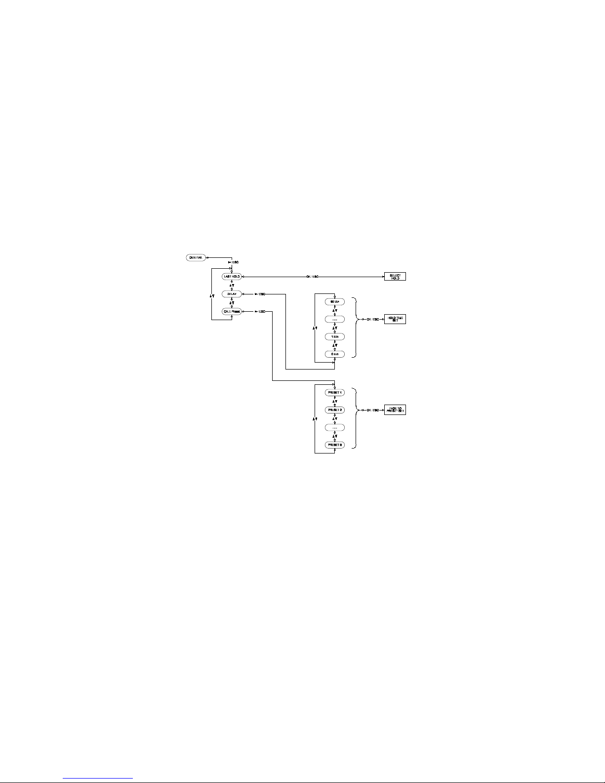
DMX Fail
For DMX fail, use Up/Down buttons to select either Call Preset 1-8, Last
Hold or Delay Fade out time. Press Right button to enter.
If you selected Call Preset, the DMX state will go to the selected preset
when the DMX input fails. Use Up/Down buttons to select preset 1-8.
Press Right button to enter.
If you selected Last Hold, the last DMX state will be held in the event of a
DMX failure.
If you selected Delay Fade out time, the DMX state will be held for the
selected period of time before fading to zero. Use Up/Down buttons to
select the fade out time of between 0-90 minutes. Press Right button to
enter.
Press OK to confirm changes, press ag ain to save or press Esc to exit
without saving any changes.
User Manual v1.2 March 2006 22
Page 23
Wallrack User Manual
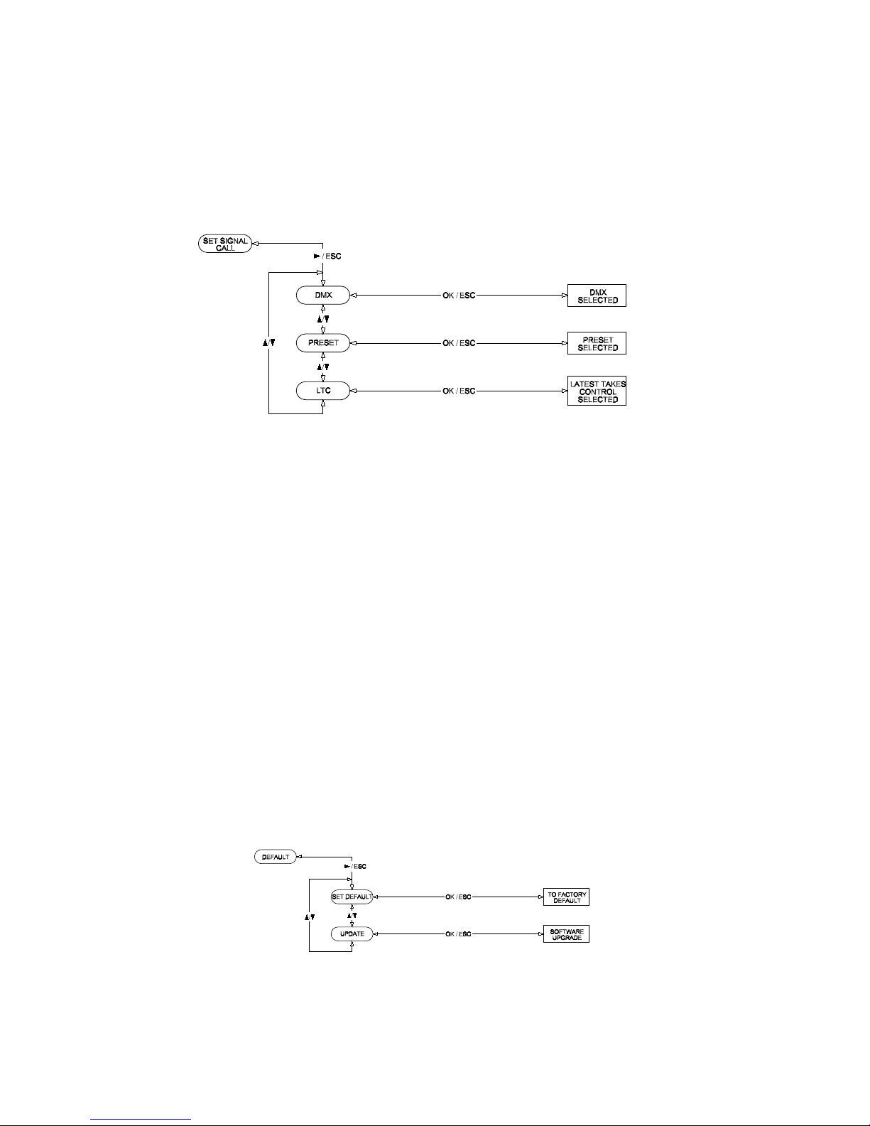
Set Signal Call
To set the Signal mode, use Up/Down buttons to select either DMX,
Preset or Latest Takes Control. Press Right button to enter.
Press OK to confirm changes, press ag ain to save or press Esc to exit
without saving any changes.
Version Number
To view the version number, press Right button and the display will show
the software version number.
Set Factory Defaults
To set the factory defaults, use Up/Down buttons to select either Default
or Update Firmware. Press Right button to enter.
Selecting Default, press OK again to confirm the re-setting of factory
default.
Selecting Update Firmware, press OK again to confirm and the firmware
will automatically upload from the upload port.
User Manual v1.2 March 2006 23
Page 24
Wallrack User Manual
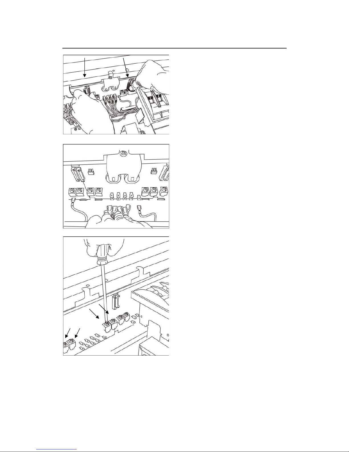
Triac Replacement
1. Disconnect the two flat cables.
2. Unplug the 2 red, 2 brown, 4 blue
and the green connectors.
(Please mark these cables before
unplugging them as you need to
replace them)
3. Unscrew the 4 choke connections.
User Manual v1.2 March 2006 24
Page 25
Wallrack User Manual
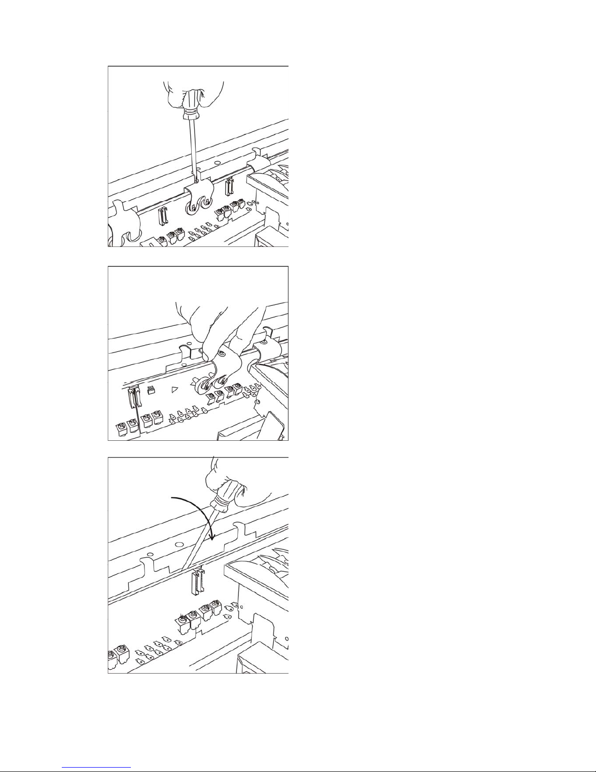
4. Unscrew the PCB clip.
5. Take out the clip as shown.
6. Click the PCB out of the slot.
User Manual v1.2 March 2006 25
Page 26
Wallrack User Manual
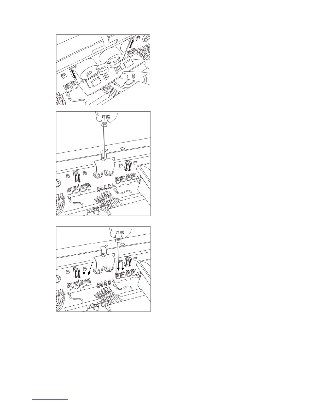
7. Replace the Triac.
8. Screw back the clip.
9. Tighten the choke connections.
User Manual v1.2 March 2006 26
Page 27
Wallrack User Manual
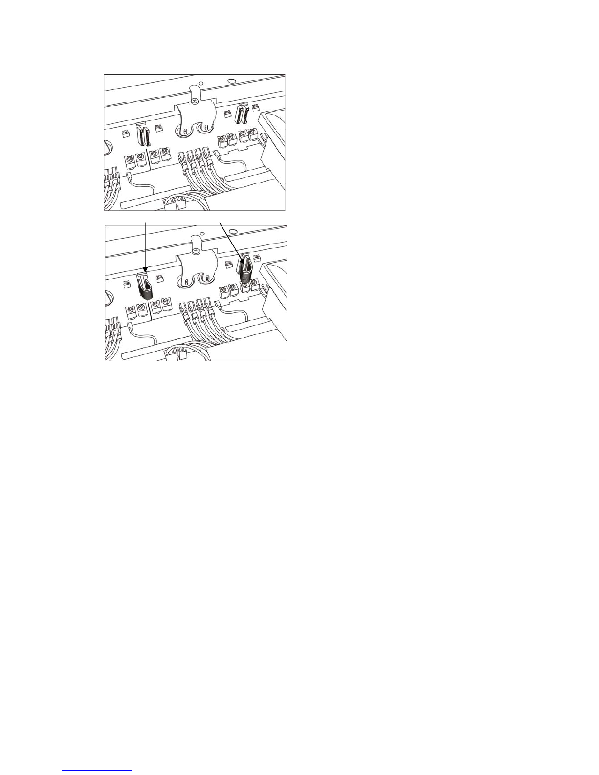
10. Plug the wires back into their original
positions. (See note 2)
11. Connect the flat cables.
User Manual v1.2 March 2006 27
 Loading...