

Page 1
Page 2

Strand Lighting Offices
Strand Lighting - Dallas
10911 Petal Street
Dallas, TX 75238
Tel: 214-647-7880
Fax: 214-647-8031
Strand Lighting - New York
267 5th A ve, 4th Floor
New York, NY 10016
Tel: 212-213-8219
Fax: 212-532-2593
Strand Lighting - Asia Limited
Room 6-10, 20/F Delta House 3 On Yiu Street
Shatin, N.T. Hong Kong
Tel: + 852 2757 3033
Fax: + 852 2757 1767
The material in this manual is for information purposes only and is subject to change without notice. Strand
Lighting assumes no responsibility for any errors or omissions which may appear in this manual. For comments and
suggestions regarding corrections and/or updates to this manual, please contact your nearest Strand Lighting office.
El contenido de este manual es solamente para información y está sujeto a cambios sin previo aviso. Strand
Lighting no asume responsabilidad por errores o omisiones que puedan aparecer. Cualquier comentario, sugerencia
o corrección con respecto a este manual, favor de dirijirlo a la oficina de Strand Lighting más cercana.
Der Inhalt dieses Handbuches ist nur für Informationszwecke gedacht, Aenderungen sind vorbehalten. Strand
Lighting uebernimmt keine Verantwortung für Fehler oder Irrtuemer, die in diesem Handbuch auftreten. Für
Bemerkungen und Verbesserungsvorschlaege oder Vorschlaege in Bezug auf Korrekturen und/oder
Aktualisierungen in diesem Handbuch, moechten wir Sie bitten, Kontakt mit der naechsten Strand LightingNiederlassung aufzunehmen.
Le matériel décrit dans ce manuel est pour information seulement et est sujet à changements sans préavis. La
compagnie Strand Lighting n'assume aucune responsibilité sur toute erreur ou ommission inscrite dans ce manuel.
Pour tous commentaires ou suggestions concernant des corrections et/ou les mises à jour de ce manuel, veuillez s'll
vous plait contacter le bureau de Strand Lighting le plus proche.
Information contained in this document may not be duplicated in full or in part by any person without prior written
approval of Strand Lighting. Its sole purpose is to provide the user with conceptual information on the equipment
mentioned. The use of this document for all other purposes is specifically prohibited.
Strand Selecon - Auckland
19-21 Kawana Street
Northcote, Auckland 0627
New Zealand
Tel: +64 9 481 0100
Fax: +64 9 481 0101
Strand Lighting - Europe
Marssteden 152
Enschede 7547 TD
The Netherlands
Tel: +31 53 4500424
Fax: +31 53 4500425
Website:
www.strandlighting.com
Document Number: 2-450186-010
Version as of: 22 June 2011
R21 Powered Raceway Installation Guide
©2011 Philips Group. All rights reserved.
Page 3
R21 Powered Raceway
IMPORTANT SAFEGUARDS
When using electrical equipment, basic safety precautions should always be followed including the following:
a. READ AND FOLLOW ALL SAFETY INSTRUCTIONS.
b. Do not use outdoors.
c. Do not mount near gas or electric heaters.
d. Equipment should be mounted in locations and at heights where it will not readily be subjected to
tampering by unauthorized personnel.
e. The use of accessory equipment not recommended by the manufacturer may cause an unsafe
condition.
f. Do not use this equipment for other than intended use.
g. Refer service to qualified personnel.
SAVE THESE INSTRUCTIONS.
Installation Guide
WARNING: You must have access to a main circuit breaker or other power disconnect device
before installing any wiring. Be sure that power is disconnected by removing fuses or turning the
main circuit breaker off before installation. Installing the device with power on may expose you to
dangerous voltage and damage the device. A qualified electrician must perform this installation.
WARNING: Refer to National Electrical Code® and local codes for cable specifications. Failure to
use proper cable can result in damage to equipment or danger to persons.
WARNING: This equipment is intended for installation in accordance with the National Electric
Code® and local regulations. It is also intended for permanent installation in indoor applications
only . Before any electrical work is performed, disconnect power at the circuit breaker or remove the
fuse to avoid shock or damage to the control. It is recommended that a qualified electrician perform
this installation.
CAUTION: Wire openings MUST have fittings or lining to protect wires/cables from damage. Use
90° C copper wire only! Aluminum wire may not be used.
1
Page 4

Installation Guide R21 Powered Raceway
TABLE OF CONTENTS
Strand Lighting Offices................................. .......................................................................Inside Fr on t Cover
Important Safeguards
Table of Contents
Preface
About This Guide ................................................................................................................................................... 3
Additional Resources.............................................................................................................................................. 3
Other Manuals................................................................................................................................................. 3
Additional Resources for DMX512................................... .................................. ............................................ 3
Overview
Installation and Checkout Sequence....................................................................................................................... 4
Components
R21 Powered Raceway........................................................................................................................................... 5
Raceway Control Modules ..................................................................................................................................... 6
Dimmer Modules.................................................................................................................................................... 7
Mechanical Considerations
Tools and Supplies........................................ .................................. .................................. ...................................... 8
Installation Location............................................................................................................................................... 8
Wire Routing........................................................................................................................................................... 9
Wiring Requirements.............................................................................................................................................. 9
Installation Procedure
Connecting Sections ............................................................................................................................................. 10
Mounting the Unit ........................................................................................................................................... ..... 10
Single-Pipe Methods ................................................................................................................................ ..... 10
Double-Pipe Methods.................................................................................................................................... 11
Threaded Rod and Wall Mount Methods...................................................................................................... 11
Connecting Power Wiring ...................................................................................................................... .............. 12
Overview ....................................................................................................................................................... 12
Line Power..................................................................................................................................................... 13
Connecting Control Wiring .................................................................................................................................. 14
Overview ....................................................................................................................................................... 14
DMX512............................................................................................................................... ......................... 15
Vision.net Networks (SVN/485)................................................................................................................... 16
Termination of Shielded Cable................................................... ... ................................. ............................... 16
Termination of Ethernet Cable.................................. ................................................................. ................... 17
Master/Slave Wiring (DIM96)...................................................................................................................... 18
Panic Input......................................................................................................................... ............................ 18
Installing Cable Tray (if applicable)..................................................................................................................... 19
Complete and Test ........................................................................................... ............................... ...................... 19
Maintenance Procedures
Replacing a Dimmer Module......................................................................................................
.......................... 20
Appendix A.
R21 Powered Raceway Dimmer DIP Switch Settings......................................................................................... 21
2 Table of Contents
Page 5

R21 Powered Raceway
Installation Guide
3
Page 6

Installation Guide R21 Powered Raceway
PREFACE
1. About This Guide
The document provides installation instructions for all configurations of the R21 Powered Raceway.
Please read all instructions before installing or using this product. Retain this guide for fu ture reference.
2. Additional Resources
Other Manuals
For additional operation, maintenance, and setup information, please see the following Strand manuals:
• R21 Powered Raceway Operation and Maintenance Guide
• Dimmer.net Software Manual
Dimmer.net software and manuals may be downloaded at www.strandlighting.com.
Additional Resources for DMX512
For more information on installing DMX512 control systems, the following publicatio n is availabl e for purchase
from the United States Institute for Theatre T echnology (USITT), "Recommended Practice for DMX512: A Guide for
Users and Installers, 2nd edition" (ISBN: 9780955703522). USITT Contact Information:
USITT
315 South Crouse Avenue, Suite 200
Syracuse, NY 13210-1844 USA
1-800-938-7488 or 1-315-463-6463
www.usitt.org
4 Preface
Page 7

R21 Powered Raceway
OVERVIEW
1. Installation and Checkout Sequence
The R21 Powered Raceway is shipped from the factory in a ready-to-install configuration. The following steps will
be required to successfully install the unit(s) at your location:
1) Unpack and Inspect
Remove all components from shipping container(s) and inspect for damage. Compare the equipment you
received to the packing list. If these do not match, contact Strand Lighting Customer Service at: 1-8004STRAND (U.S.) or 1-214-647-7880 (international).
2) Review ALL Instructions
Read this entire installation guide before you start the installation.
3) Gather Tools
Obtain all tools and supplies listed in "Tools and Supplies" on page 9.
4) Choose Appropriate Installation Location
Ensure installation location meets the requirements listed in "Installation Location" on page 9.
Installation Guide
5) Plan Wire Routing
Decide where line and control wiring will enter the unit.
6) Install Unit
Following the instructions provided in "Installation Procedure" on page 11, mount and wire the unit.
7) Checkout
Perform the steps listed in "Complete and Test" on page 20 to ensure that the unit has been properly installed.
8) Call For Approval
Do not energize the R21 Powered Raceway until the wiring has been approved by an authorized technician. Call
Strand Lighting to schedule an Engineering Checkout.
Installation and Checkout Sequence 5
Page 8
Installation Guide R21 Powered Raceway
COMPONENTS
1. R21 Powered Raceway
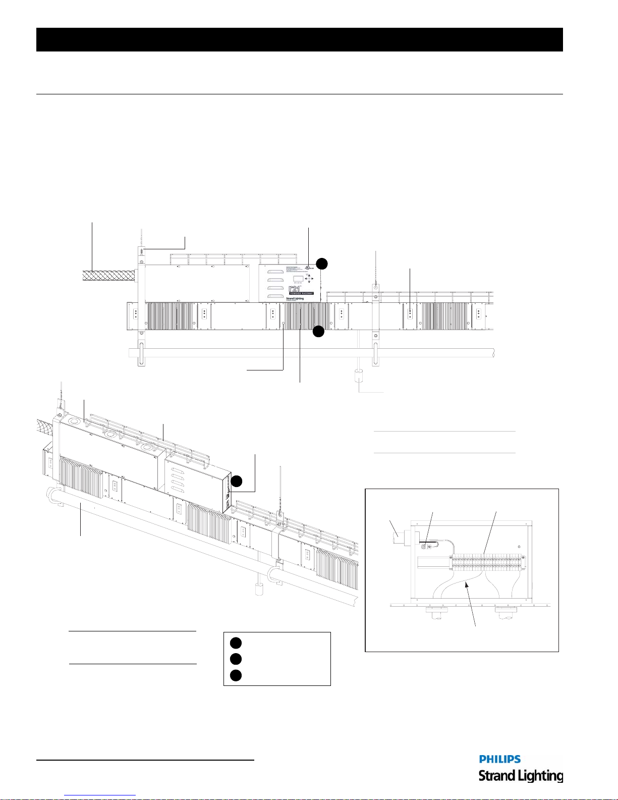
The R21 Powered Raceway - up to 96 feet long - contains one Raceway Control Module (RCM), up to forty-eight
20A Dual Dimmer Modules, and at least one Power Terminal Box (PTB). The number of Power Terminal Boxes is
determined by the location and the number of necessary power feeds.
Power Feed Multi-conductor Cable
with Strain Relief (optional)
FRONT VIEW
Power Terminal Box (PTB)
Control Cable
Tray (optional)
Hanger Bracket
- six types available
Focus Button /
LED Indicator
Raceway Control Module (RCM)
Located on Raceway or Rack Mount
Dual Dimmer Module
(2400 Watt total)
DMX512 In/Thru Connectors,
RJ45 Ethernet Connector &
Serial Connector (diagnostic)
B
Flush Receptacle (choice of stage pin,
A
twistlock, or Edison connectors)
C
Pigtail Receptacle - Standard Length 18"
(choice of stagepin, twistlock, or Edison
connectors)
EXAMPLE CONFIGURATION
Raceway Components May Vary
Power Terminal Box Interior View (Typical)
1-1/2" Schedule 40 Pipe
(provided by others)
SIDE VIEW
Note: All components are pre-wired
at the factory except terminal box
line input connections.
Figure 1: R21 Powered Raceway Component Overview
6 Components
A
See next pages
B
for detail illustrations
C
Input
Power
Feed
Ground Terminal
Output Power Wiring
(pre-wired at factory)
Input Power Terminals
Page 9
R21 Powered Raceway
2. Raceway Control Modules
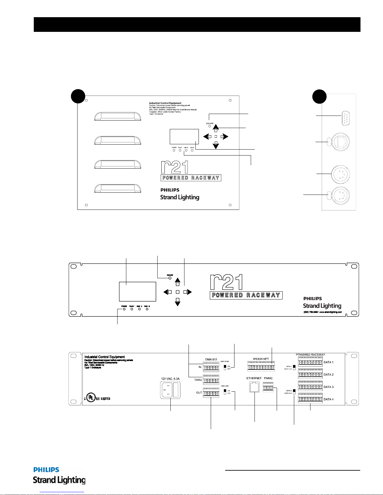
The Raceway Control Module (RCM) is used to configure the R21 Powered Raceway. The RCM comes in two
configurations, a 19-inch "rack mount" configuration for remote applications or a "head end" configuration for local
applications.
Installation Guide
A
Menu
Display
Escape
Button
Menu Navigation
and Enter Buttons
Menu
Display
Status
LEDs
DMX512-Over-Ethernet Output
(Ethernet Enabled Units)
DMX512 Thru
(DMX Only Units)
Figure 2: Head End RCM Component Detail
Escape
Button
Menu Navigation
and Enter Buttons
B
Serial Port
Ethernet
Port
DMX512 In
- or -
SIDE VIEWFRONT VIEW
FRONT VIEW
Status
LEDs
REAR VIEW
DMX512 In & Thru
(DMX Only Units)
A/C Input
DMX512-Over-Ethernet
Output (Ethernet-Enabled Units)
DMX512
Termination
DMX512
Ground
Vision.net Port
Ethernet
Port
Figure 3: Rack Mount RCM Components
Panic
Input
Data Ports
Data Port
Enable Switches
Raceway Control Modules 7
Page 10
Installation Guide R21 Powered Raceway
3. Dimmer Modules
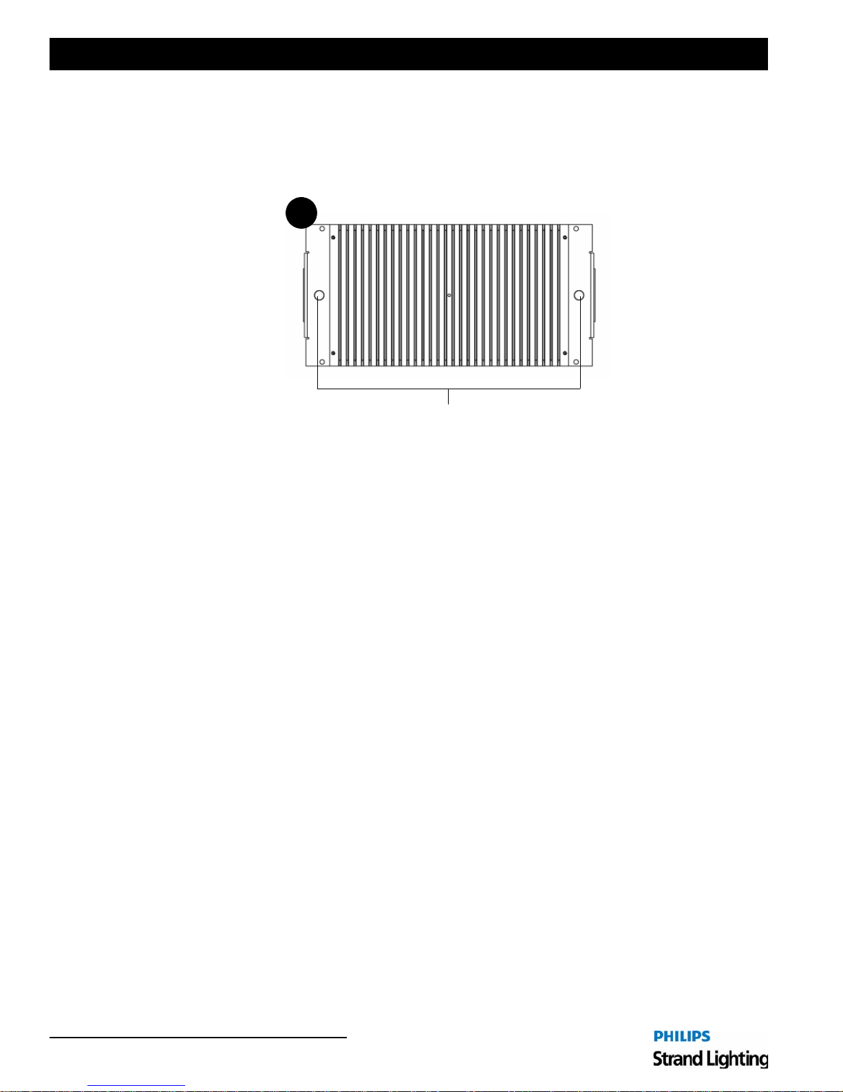
R21 Powered Raceway Dimmer Modules contain one 20A dual dimmer with 20A (2400W) power shared between
the two dimmers. Each dual dimmer module includes two Focus/LED Indicator buttons, which function as both focus
adjustment controls and status indicators.
C
Focus Button /
LED Indicator
Figure 4: Dimmer Module Detail
8 Components
Page 11
R21 Powered Raceway
MECHANICAL CONSIDERATIONS
1. Tools and Supplies
The following tools and supplies will be required:
• Phillips and slotted screwdrivers
• Adjustable open-ended wrench
• Ratchet and assorted socket set
• Wire cutter and stripper
• Cable/box connecto rs and fittings
• Digital voltmeter / RMS
• Hammer (for terminal box knock-out holes)
Note: This is a basic list. Depending on your specific installation, additional tools may be required.
Installation Guide
2. Installation Location
The location planned for installation MUST meet the following requirements:
• Weight Load Capacity - The R21 Powered Raceway should be installed using mounting brackets with sufficient
load capacity to support it. Choose one of six approved mounting configurations. Refer to "Mounting the Unit" on
page 11.
• Ventilation Allowance - The room must have sufficient space to allow air to circulate and cool. The R21 Powered
Raceway must have a minimum of 12 inches of clear space above it to allow for proper convection cooling.
• Indoor Use Only - The R21 Powered Raceway is rated for indoor use only.
• Dry Locations Only - The R21 Powered Raceway can only be installed in an "office clean" area that is never
exposed to moisture of any kind. Strand Lighting is not responsible for damage to equipment caus ed by paint, dus t,
solvents or cleaning supplies.
CAUTION: Refer to National Electrical Code® and local codes to determine whether additional requirements must
be met.
Tools and Supplies 9
Page 12
Installation Guide R21 Powered Raceway
3. Wire Routing
Before deciding a final mounting position, consider all wire routing as follows:
• Line power wiring may enter the uni t through the top or side of the Power Terminal Box. Refer to "R21 Powered
Raceway" on page 6.
Note: The RCM does not contain any field serviceable components.
WARNING! You must have access to a main circuit breaker or other power disconnect devices in order to install any
wiring. Failure to disconnect power before installing or servicing the unit may result in injury.
4. Wiring Requirements
• For control wire-type requirements, refer to your job drawings as prepared by Strand Lighting.
• For power wire-type requirements, refer to Strand Lighting drawings, contract drawings, and applicable codes.
10 Mechanical Considerations
Page 13
R21 Powered Raceway
INSTALLATION PROCEDURE
1. Connecting Sections
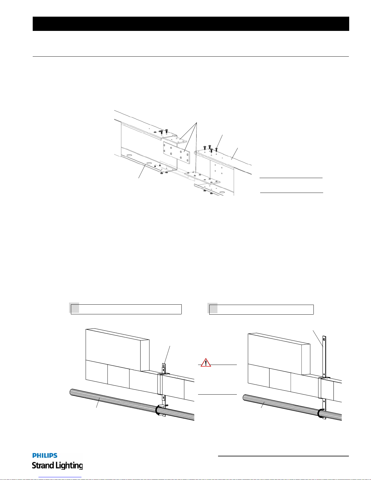
Before mounting the R21 Powered Raceway, it will be necessary to connect all modular sections. Sections are
connected using three metal connector plates and screws (provided). Refer to Figure 5 below.
Installation Guide
Connector Plates
10-32 Screw (eight per plate)
R21 Powered Raceway Section
R21 Powered Raceway Section
Note: Some components and
wiring not shown for clarity.
Figure 5: Connecting Modular Sections
2. Mounting the Unit
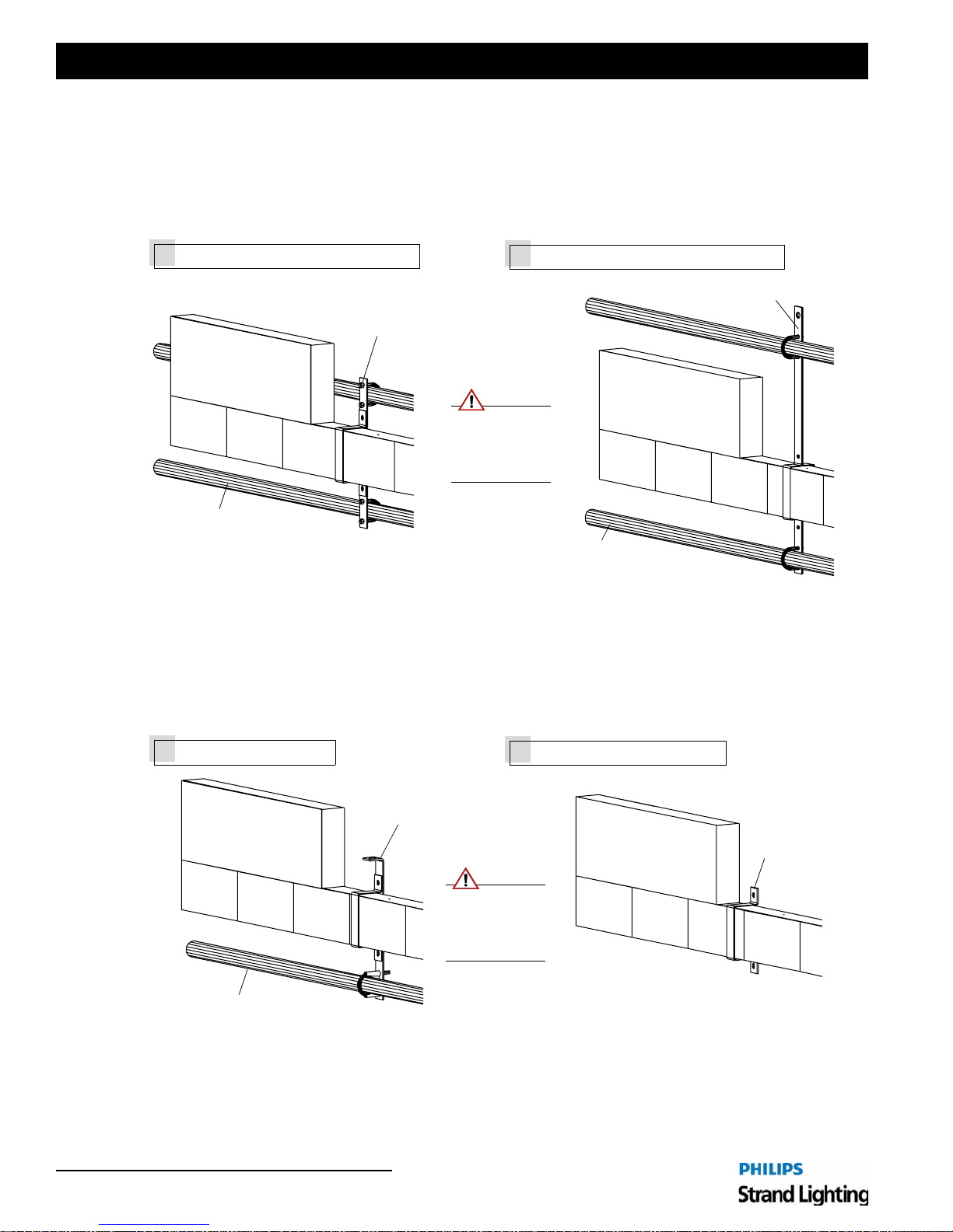
The R21 Powered Raceway can be mounted in one of six configurations depending on your specific requirements.
Regardless of type, brackets cannot be spaced more than 5 feet apart per National Electrical Code®.
Single-Pipe Methods
The 71444 Single-Pipe Overhung Hanger Bracket is used to attach an R21 Powered Raceway to a single 1-1/2"
schedule 40 pipe with no additional overhead support.
The 71440 Single-Pipe Rigged Hanger Bracket is used to suspend a single 1-1/2" schedule 40 pipe and an R21
Powered Raceway from a rigging system or a ceiling.
Single-Pipe Overhung Hanger Bracket
1
Single-Pipe Overhung
Hanger Bracket (71444)
Single-Pipe Rigged Hanger Bracket
2
Single-Pipe Rigged
Hanger Bracket (71440)
1-1/2" Schedule 40
Pipe (not provided)
CAUTION:
Brackets must be
spaced every five
feet or less per
NEC® requirements.
1-1/2" Schedule 40
Pipe (not provided)
Figure 6: Single-Pipe Methods
Connecting Sections 11
Page 14
Installation Guide R21 Powered Raceway
Double-Pipe Methods
The 71443 Double-Pipe Offset Hanger Bracket is used to attach an R21 Powered Raceway to two 1-1/2" schedule 40
pipes with no additional overhead support. Components are supported in an offset position in front of the two battens.
The 71441 Double-Pipe Rigged Hanger Bracket is used to suspend two 1-1/2" schedule 40 pipes and an R21 Powered
Raceway from a rigging system. Components are supported midway between the two battens.
Double-Pipe Offset Hanger Bracket
3
Double-Pipe Offset
Hanger Bracket (71443)
1-1/2" Schedule 40
Pipe (not provided)
CAUTION:
Brackets must be
spaced every five
feet or less per
NEC® requirements.
Double-Pipe Rigged Hanger Bracket
4
Double-Pipe Rigged
Hanger Bracket (71441)
1-1/2" Schedule 40
Pipe (not provided)
Figure 7: Double-Pipe Methods
Threaded Rod and Wall Mount Methods
The 71445 Threaded Rod Bracket is used to suspend one 1-1/2" schedule 40 pipe and an R21 Powered Raceway from
a rigging system using threaded rod support.
The 71442 Wall Mount Hanger Bracket is used to permanently mount an R21 Powered Raceway to a wall.
Threaded Rod Bracket
5
1-1/2" Schedule 40
Pipe (not provided)
12 Installation Procedure
Wall Mount Hanger Bracket
6
Threaded Rod Bracket
(71445)
CAUTION:
Brackets must be
spaced every five
feet or less per
NEC® requirements.
Figure 8: Threaded Rod and Wall Mount Methods
Wall Mount
Hanger Bracket
(71442)
Page 15
R21 Powered Raceway
3. Connecting Power Wiring
Overview
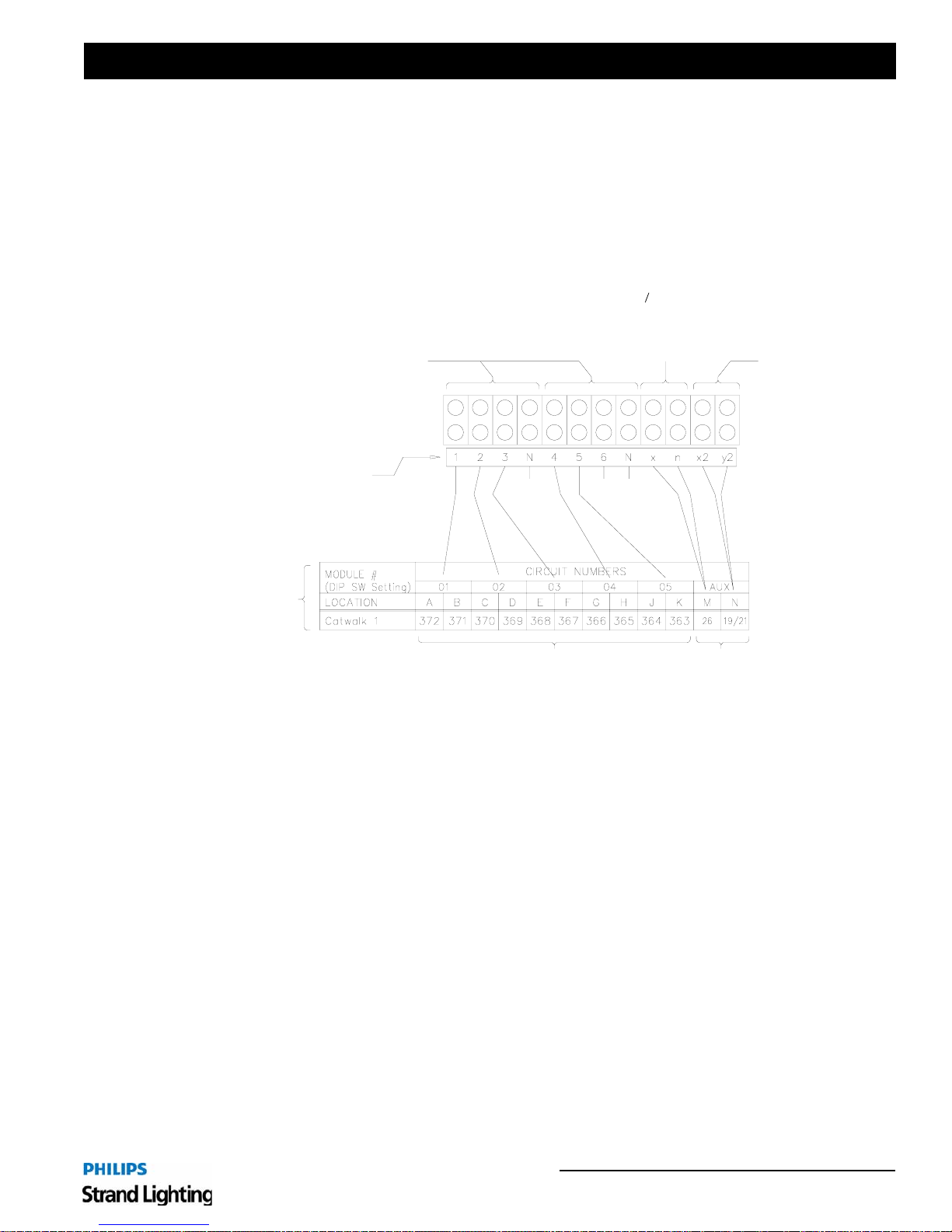
The R21 Powered Raceway is designed to be wired from the top or side of the Power Terminal Box (see
Figure 10 on next page). Eight knock-out holes are provided (four on top, two on each side) for this purpose. We
recommend connecting the Line Power wiring and Grounds (if applicable) first, and the Load Neutral and Load Hot
wires last. Refer to Figure 9 below for wiring key.
3-Phase, 4 Wire Blocks
120/208 VAC
20 Amp Circuits
(Sixth module not used in this
example - terminals always
provided in 3-Phase, 4 Wire
blocks.)
Label on Terminal Strip #’s correspond to module ID
Neutral
for
1, 2, 3
Installation Guide
Single-Phase, 2 Wire Blocks
120 VAC
20 Amp Aux Circuit
(if applicable)
208 VAC
20 Amp
Aux Circuit
(if applicable)
Neutral
for
4, 5, 6
Circuit schedule
from project
drawings
Dimmer Numbers
Figure 9: Terminal Box Wiring Key
Aux Ckt Numbers from Panelboard
(this shows 1: 1-Pole and 1: 2-Pole)
Connecting Power Wiring 13
Page 16
Installation Guide R21 Powered Raceway
Line Power
WARNING! You must have access to a main circuit breaker or other power disconnect devices in order to install any
wiring. Failure to disconnect power before installing or servicing the unit may result in injury.
WARNING! Refer to National Electrical Code® and local codes for cable specifications. Failure to use proper cable
can result in damage to equipment or danger to persons.
CAUTION: Wire openings MUST have fittings or lining to protect wires/cables from damage.
CAUTION: Use 90° C copper wire only!
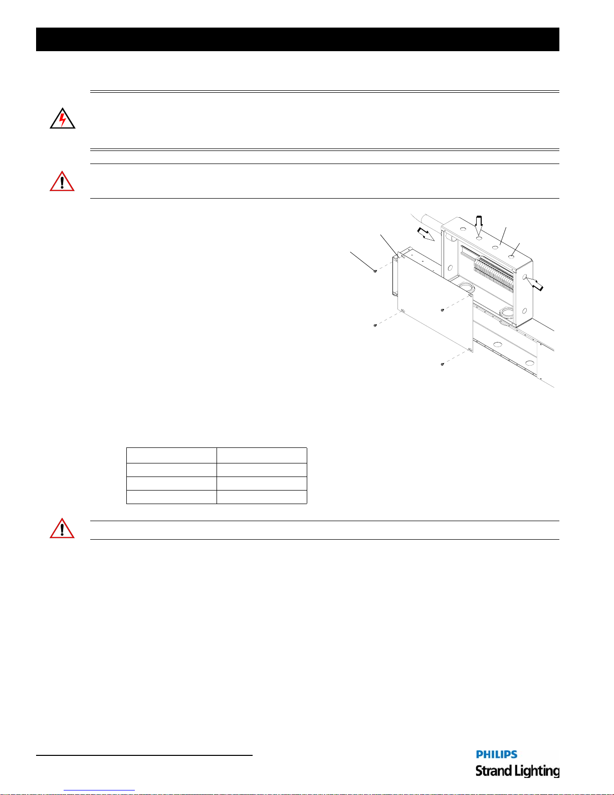
To connect Line Power:
Step 1. Turn off all power at main breaker or
disconnect device.
Terminal Box Cover
Screw
Terminal Box
Input Hole
Step 2. Route line power wiring from power source to
top or side of terminal box (Figure 10).
Step 3. Remove terminal box cover.
Step 4. Punch holes as required and install conduit
fittings or lining materials into opening.
Step 5. Feed line power cables through prepared
openings.
Step 6. At end of each cable, strip insulation as
appropriate.
Step 7. Dress all wires to back of box.
Figure 10: Removing Terminal Box Cover
Step 8. At appropriate lugs, terminate Phase, Neutral and Ground wires. Line connections are color coded as
follows:
Wire Color
Phase A Black
Phase B Red
Phase C Blue
CAUTION: Failure to use proper torque setting will cause premature equipment failure.
Step 9. Tighten lug set screws to proper torque settings as provided by label inside terminal box.
14 Installation Procedure
Page 17
R21 Powered Raceway
4. Connecting Control Wiring
Overview
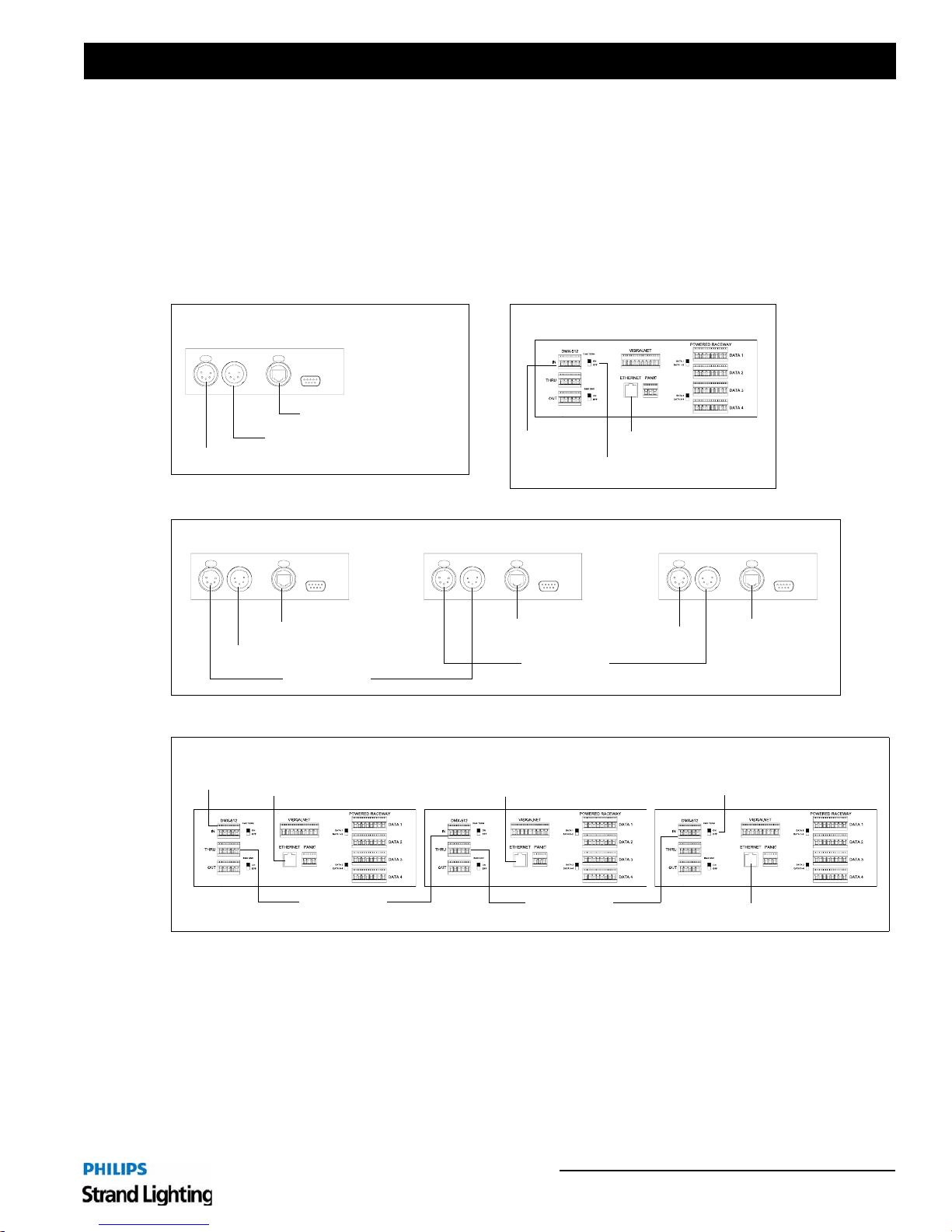
For details regarding the specific low-voltage control cable wiring for your project, refer to your project drawings as
prepared by Strand Lighting. The low-voltage control cable will connect to the R21 Raceway Control Module
(RCM). The RCM comes in two configurations, a 19-inch "rack mount" configuration for remote applications or a
"head end" configuration for local applications. These generic details are for reference only, consult your project
drawings for final connection details.
Installation Guide
Single R21 Powered Raceway - Head End Model
Ethernet In
Termination
DMX512 In
Multiple R21 Powered Raceways - Head End Model
Ethernet In
DMX512 In
DMX512 Thru
Multiple R21 Powered Raceways - Rack Model
Single R21 Powered Raceway - Rack Model
DMX512 In
Ethernet In
DMX512 Thru
Ethernet In
Termination
Termination
Ethernet In
DMX512 In
Ethernet In
DMX512 Thru
Ethernet In
DMX512 Thru
Figure 11: Example Control Connections
Termination
Ethernet In
Connecting Control Wiring 15
Page 18
Installation Guide R21 Powered Raceway
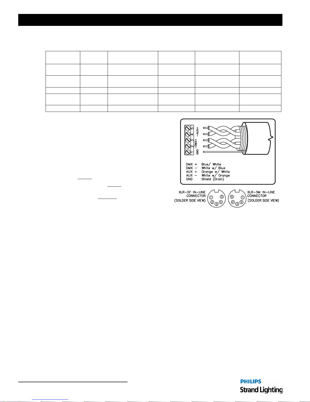
DMX512
DMX512
Terminal
GND 1 Drain Wire (Shield) Drain (Shield) Drain (Shield)
DMX - 2 White w/ Blue Black
DMX + 3 Blue w/ White White Red White/Orange (1)
AUX - 4 White w/ Orange Red
AUX + 5 Orange w/ White Green White Green/White (3)
XLR Pin
Name
WE Color Code
(e.g., Belden #8132)
IECA Color
Code
Belden Standard
Color Code
Black
(of Red pair)
Black
(of White pair)
Color Code
Brown (8)
White/Brown (7)
Orange (2)
Green (6)
Contractor is Responsible for All Terminations
1) Only approved EIA-485 cable type s may be used.
Approved types are:
Belden #9829 and TMB Proplex #PC224T
An acceptable plenum rated cable is: Belden
#89729.
2) Category 5e cable may be used for DMX512.
Approved types are: Belden #1583A and Belden
#1585A (Plenum).
3) Cable MUST
4) DMX512 cable runs MUST
be terminated exactly as shown here.
be routed in a "DaisyChain" configuration as shown in your drawing
set, if provided. DO NOT
convert these cables to
home runs.
5) DMX512 cable runs should all be in metal conduit.
Female Male
Runs in exposed areas must be in metal conduit.
Maximum cable run should not exceed 1000 feet.
CAT5e
or EQUAL
(NOT BY STRAND)
BELDEN #9829
Additional Resources for DMX512
For more information on installing DMX512 control systems, the following publicatio n is availabl e for purchase
from the United States Institute for Theatre Technology (USITT):
• Recommended Practice fo r DMX512: A Guide for Users and Installers, 2nd edition (ISBN: 9780955703522)
USITT contact information:
USITT
6443 Ridings Road
Syracuse, NY 13206-1111 USA
1-800-93USITT
www.usitt.org
16 Installation Procedure
Page 19
R21 Powered Raceway
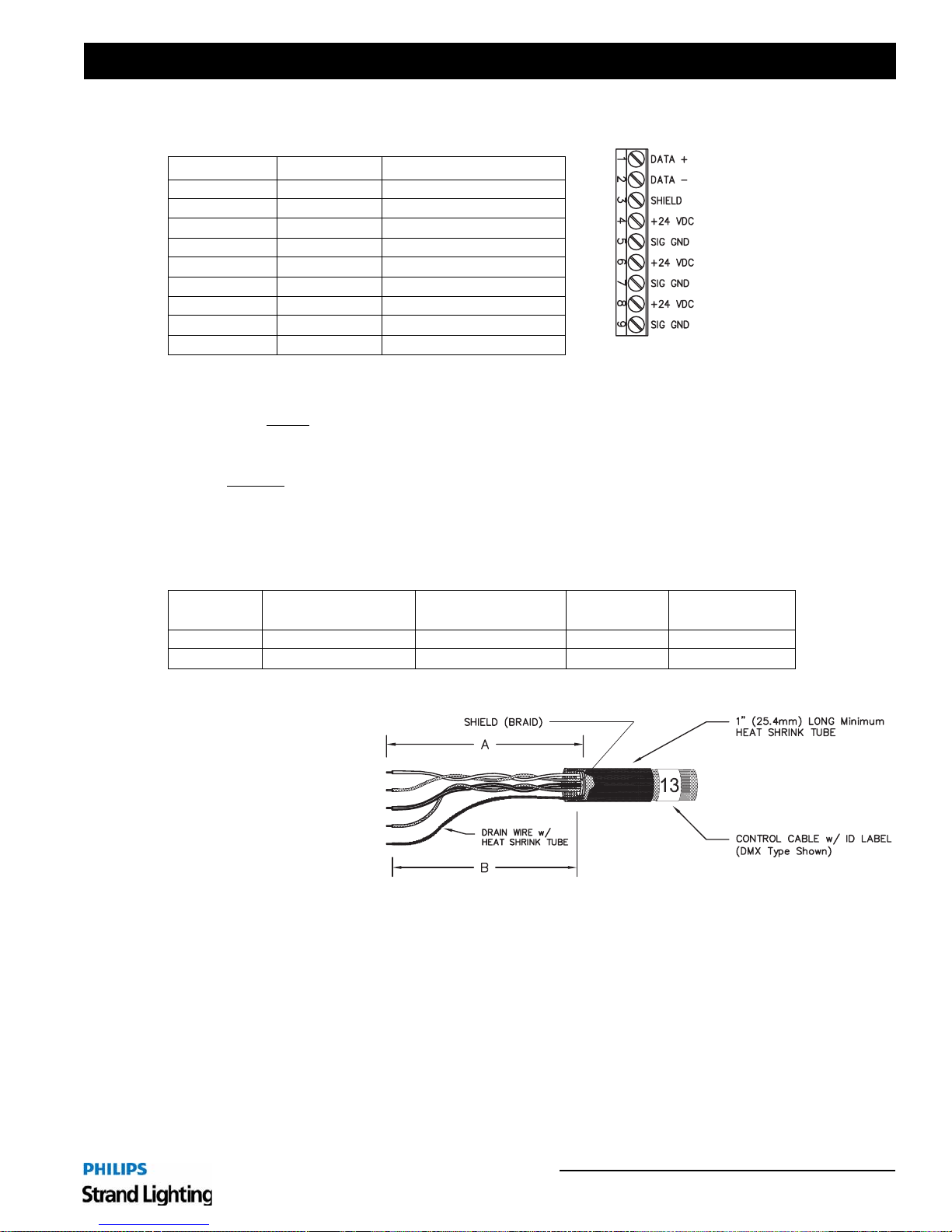
Vision.net Networks (SVN/485)
Pin Number Signal Name CAT5e Wire Color
1 Data + White w/ Orange
2 Data - Orange
3SHIELD Shield
4 +24 VDC White w/ Green
5 Signal GND Green
6 +24 VDC White w/ Blue
7 Signal GND Blue
8 +24 VDC White w/ Brown
9 Signal GND Brown
Contractor is Responsible for All Terminations
1) Only approved cable types may be used. Approved types are: Belden #1583A and Belden #1585A
2) Cable MUST
NOT exceed 1000 feet.
3) Cable runs should be routed in a "Daisy-Chain" configuration as shown in your drawing set, if provided.
DO NOT
4) Maximum station quant ity subject to power supply and system requirements. Please consult factory for
specific information.
Installation Guide
be terminated exactly as shown here. Total length of cable in Vision.net Network W iring must
convert these cables to home runs.
Termination of Shielded Cable
Dimension Name Minimum
A Remove Cable Jacket 1" (25.4mm) 2-1/4" (60mm) 1-1/4" (31.8mm)
B Drain Wire Heatshrink Dim 'A' - 1/8" (3.2mm) - -
Maximum for
Terminal
To terminate shielded cable:
Step 1. Strip off specified
length of outer jacket.
Step 2. Cut shield (foil or
braid) flush to outer
jacket. DO NOT cut
drain wire.
Step 3. Fit specified length of
1/16" heat shrink
tubing over the drain
wire.
Step 4. For solder connections, fit a 1/2" length of 1/16" heat shrink tubing over each conductor.
Step 5. Fit a 1" length of 3/8" heat shrink tubing over the entire cable. Position it so that 3/4" of its length is over the
cable jacketing, and 1/4" of its length is over the loose conductors.
Step 6. Strip 1/8" inch of the insulation from each of the conductors.
Step 7. Terminate the conductors on the terminal block, or solder the terminals as specified.
Step 8. For solder connections, shrink the individual 1/2" lengths of heat shrink tubing over the so lder terminals.
Step 9. Shrink the remaining heat shrink tubing.
Step 10. Apply the appropriate ID label to the cable at the end of the outer heat shrink tubing.
Maximum for
LXR (In-Line)
Connecting Control Wiring 17
Page 20
Installation Guide R21 Powered Raceway
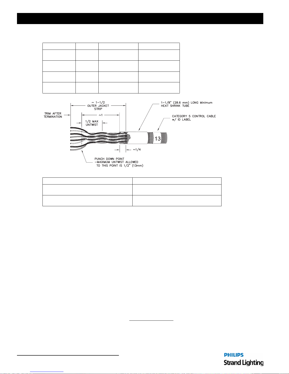
Termination of Ethernet Cable
Function Pair # Pin Out (T568B) Wire Color
(T1)
(R1)
Tx + (T2)
Tx - (R2)
Rx + (T3)
Rx - (R3)
(T4)
(R4)
1
2
3
4
5
4
1
2
3
6
7
8
White w/ Blue
Blue
White w/ Orange
Orange
White w/ Green
Green
White w/ Brown
Brown
Cable Type (10/100 Base-T Ethernet) Description
Belden #1583A
Nominal O.D. 0.214” (5.54 mm )
Belden #1585A
Nominal O.D. 0.206” (5.23 mm )
CATEGORY 5e: Non-plenum rated
4-Unshielded Twisted Pairs (UTP) #24 AWG
CATEGORY 5e: Plenum rated
4-Unshielded Twisted Pairs (UTP) #24 AWG
To terminate Ethernet cable:
Step 1. Strip off outer jacket - approximately 1-1/2" (37.6mm)
Step 2. Fit a piece of 1-1/8" (28.6mm) long heat shrink tubing over the cable extending out 1/4" (8.25mm) from
outer jacket.
Step 3. Terminate approximately 1/2" (12.2mm) from end of conductors on Type 110 punch down block or
connector per schedule (T568B)
• Maximum untwist of conductors to terminations is 1/2" (12.2mm)
• Trim excess leads.
Step 4. Shrink tubing and add appropriate ID label to the cable at the end of the heat shrink tubing.
System topology and labeling should follow TIA/EIA-568B and TIA/EIA-606 as applicable.
Per TIA/EIA-568B, Maximum length of any horizontal cable run (i.e. between Ethernet RJ-45 receptacle (work area)
and Patch Panel) is 90 meters; Maximum length of any CATEGORY 5e cables at the Ethernet RJ-45 receptacle (work
area) is 3 meters.
Ethernet equipment (e.g. Patch Panels, Hubs or Switches) should be maintained in an environment of 18°-24° C (64°
- 75° F) and 30% - 55% relative humidity per TIA/EIA-569-A.
Maximum length of any segment (cable run - including device cables
- between Hub or Switch and Node) is 90
meters. Maximum network diameter (distance between any two Nodes) is 180 meters.
18 Installation Procedure
Page 21
R21 Powered Raceway
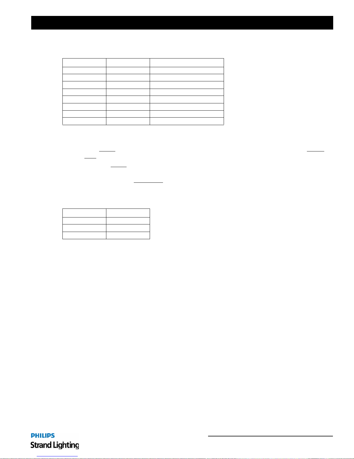
Master/Slave Wiring (DIM96)
Pin Number Signal Name CAT5e Wire Color
1 + 24 VDC White w/ Orange
2 +24 VDC Orange
3 + RX White w/ Green
4 - RX Green
5 + TX White w/ Blue
6- TX Blue
7 GND White w/ Brown
8GND Brown
Contractor is Responsible for All Terminations
1) Only approved cable types may be used. CAT5e is the only approved type.
2) Cable MUST
NOT exceed 1000 feet.
3) Cable runs MUST
4) Total number of dimmers (Dual Dimmer Modules = 2 dimmers; Quad Dimmer Modules = 4 dimmers) in
Master/Slave system MUST NOT
Installation Guide
be terminated exactly as shown here. Total length of cable in Master/Slave wiring MUST
be routed in a "Daisy-Chain" configuration as shown in your drawing set, if provided.
exceed 96 total dimmers.
Panic Input
Pin Number Signal Name
1NC
2IN
3COM
Contractor is Responsible for All Terminations
1) To be used with:
PANIC INPUT #1 - Fire Alarm Input (activates Preset 8)
PANIC INPUT #2 - Panic Input (activates Preset 7)
2) Only to be used with Dry Contact Input.
Connecting Control Wiring 19
Page 22
Installation Guide R21 Powered Raceway
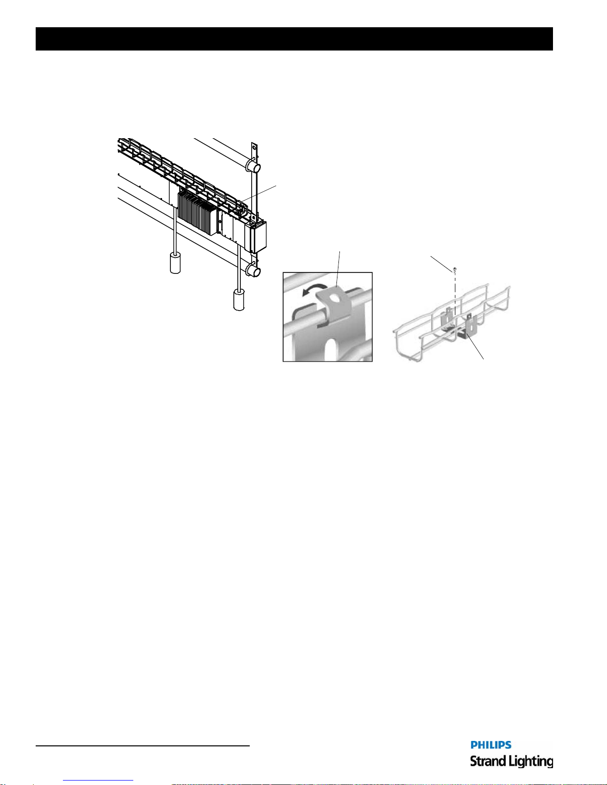
5. Installing Cable Tray (if applicable)
Once the R21 Powered Raceway is mounted, install the cable tray (basket) if this optional component has been
included. The cable tray is installed using the appropriate holes at the top of the unit. Dress control cables in cable
tray as required.
Cable Tray (optional)
Screw Holes are provided on Top of R21 Powered
Raceway to Secure Cable Tray Clips
Bend tabs
to secure tray
Screw installed through Clip into
R21 Powered Raceway Top Cover
(Screws are provided with Cable Tray)
Cable Tray Clips
Figure 12: Installing Cable Tray Finish and Test
6. Complete and Test
After the unit is mounted and wired, use the following procedures to finish out the installation and test for proper
connection.
1) Clean
Remove all metal pieces, shavings and wire scraps from Power Terminal Box. Vacuum out any dust or dirt.
2) Double Check Terminations
Check for loose connectors, improperly torqued terminations, bare wires, and damaged insulation.
3) Check Line Power Wiring
Using a digital voltmeter, check resistance between phases. The following results are typical:
• Resistance phase to phase should be 10 MΩ or higher.
• Resistance all phases to ground should be 10 MΩ or higher.
• Resistance neutral to ground should be 0Ω.
• Resistance phase to neutral should be 10Ω or higher.
4) Call For Approval
Do not energize your R21 Powered Raceway until the wiring has been approved by an authorized technician.
Call Strand Lighting to schedule an Engineering Checkout.
20 Installation Procedure
Page 23
R21 Powered Raceway
MAINTENANCE PROCEDURES
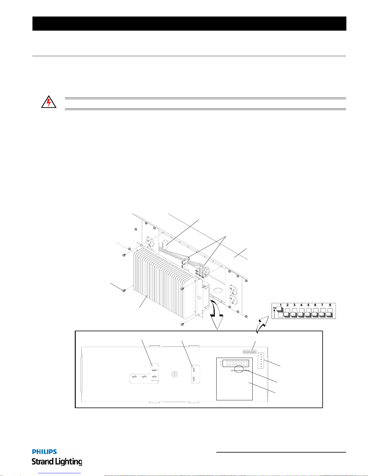
1. Replacing a Dimmer Module
Raceway dimmer modules are easy to remove or insert.
WARNING! Failure to disconnect power before servicing may result in injury.
To replace a dimmer module:
Step 1. Turn off all power to R21 Powered Raceway.
Step 2. At dimmer module, loosen four screws and partially remove from system (Figure 13).
Step 3. Disconnect all wiring and completely remove module.
Step 4. At new dimmer module, set DIP switches to same address as previous module (indicated on dimmer module
back panel label). Note: The address must exactly match the address of the dimmer being replaced. Failure
to re-address the new dimmer will result in improper operation.
Step 5. Connect three Neutral connections, 1 Line, Load A and Load B to new dimmer module.
Step 6. Insert new module into Raceway and replace four mounting screws.
Step 7. Power up and test.
Installation Guide
Screw (4 each)
Dimmer Module
Dimmer Back Panel
Line and Neutral
N
NN
Load A and B
L
Control Wiring Connection
(Low Voltage)
Load/Line/Neutral Connections
R21 Powered Raceway Section
DIP Switches
ON
OFF
Module Address
A
B
Warning
↑
12
DIP Switches
Control Input
DIP Switch Setting
Label
Figure 13: Removing and Replacing a Dimmer Module
Replacing a Dimmer Module 21
Page 24
Installation Guide R21 Powered Raceway
APPENDIX A.
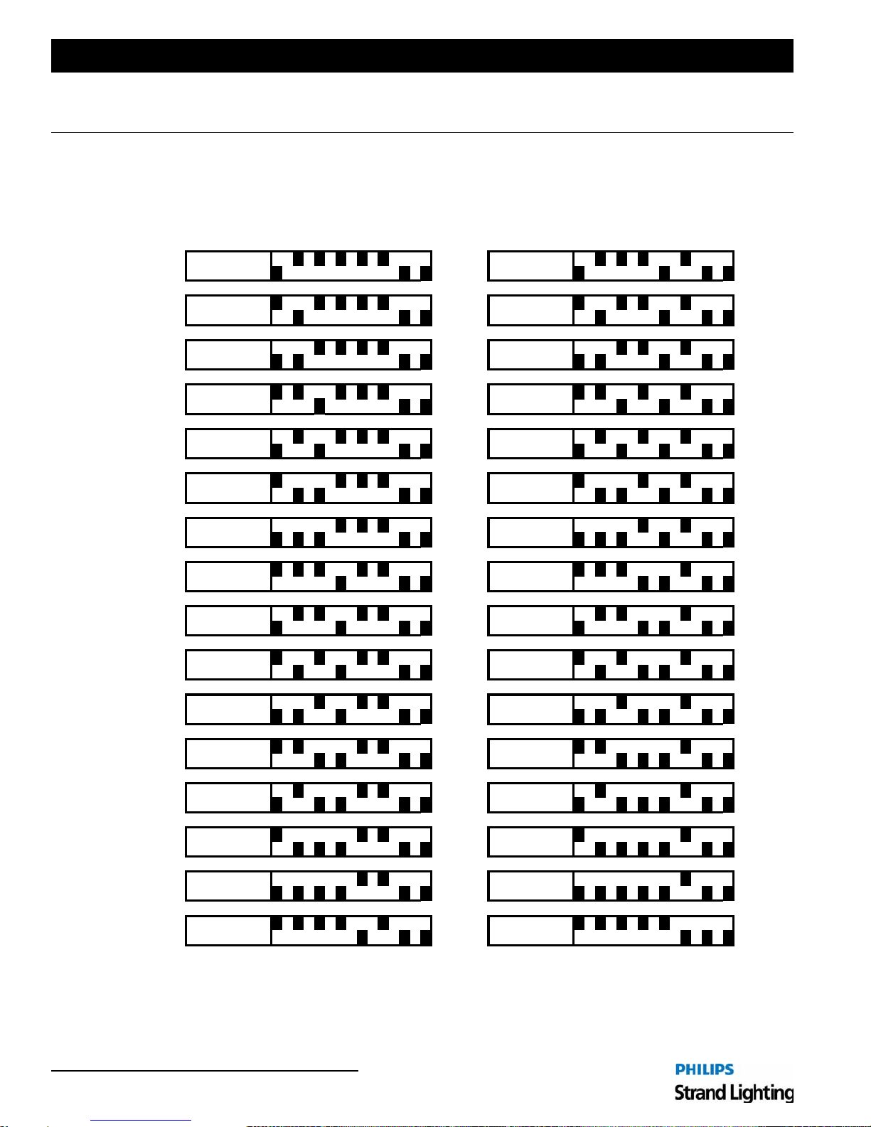
1. R21 Powered Raceway Dimmer DIP Switch Settings
8765432187654321
41
71eludoM1eludoM
8765432187654321
81eludoM2eludoM
8765432187654321
91eludoM3eludoM
432187654321
02eludoM4eludoM
12eludoM5eludoM
22eludoM6eludoM
32eludoM7eludoM
42eludoM8eludoM
52eludoM9eludoM
62eludoM01eludoM
72eludoM11eludoM
82eludoM21eludoM
92eludoM31eludoM
03eludoM41eludoM
13eludoM51eludoM
23eludoM61eludoM
8765
8765432187654321
8765432187654321
876543218
8765432187654321
8765432187654321
8765432187654
8765432187654321
8765432187654321
87654321876543
8765432187654321
8765432187654321
876543218765432
Dimmer 1-2
Dimmer 3-4 Dimmer 35-36
Dimmer 5-6 Dimmer 37-38
Dimmer 7-8 Dimmer 39-40
Dimmer 9-10 Dimmer 42-42
Dimmer 11-12 Dimmer 43-44
7654321
Dimmer 13-14
Dimmer 15-16 Dimmer 47-48
Dimmer 17-18 Dimmer 49-50
321
Dimmer 19-20
Dimmer 21-22 Dimmer 53-54
Dimmer 23-24 Dimmer 55-56
21
Dimmer 25-26 Dimmer 57-58
Dimmer 27-28 Dimmer 59-60
Dimmer 29-30
1
Dimmer 31-32 Dimmer 63-64
Dimmer 33-34
Dimmer 45-46
Dimmer 51-52
Dimmer 61-62
22 Appendix A.
Figure 14: Dimmer DIP Switch Setting Chart (Part 1)
Page 25
R21 Powered Raceway
Module 33 Module ?? xxxxxx
Dimmer 65-66 Dimmer ??-?? xxxxxx
Module 34
Dimmer 67-68
Module 35
Dimmer 69-70
Module 36
Dimmer 71-72
Module 37
Dimmer 73-74
Module 38
Dimmer 75-76
Module 39
Dimmer 77-78
Module 40
Dimmer 79-80
Module 41
Dimmer 81-82
Module 42
Dimmer 83-84
Module 43
Dimmer 85-86
Module 44
Dimmer 87-88
Module 45
Dimmer 89-90
Module 46
Dimmer 91-92
Module 47
Dimmer 93-94
Module 48
Dimmer 95-96
12345678
12345678
12345678
12345678
12345678
12345678
12345678
12345678
12345678
12345678
12345678
12345678
12345678
12345678
12345678
Installation Guide
8765432187654321
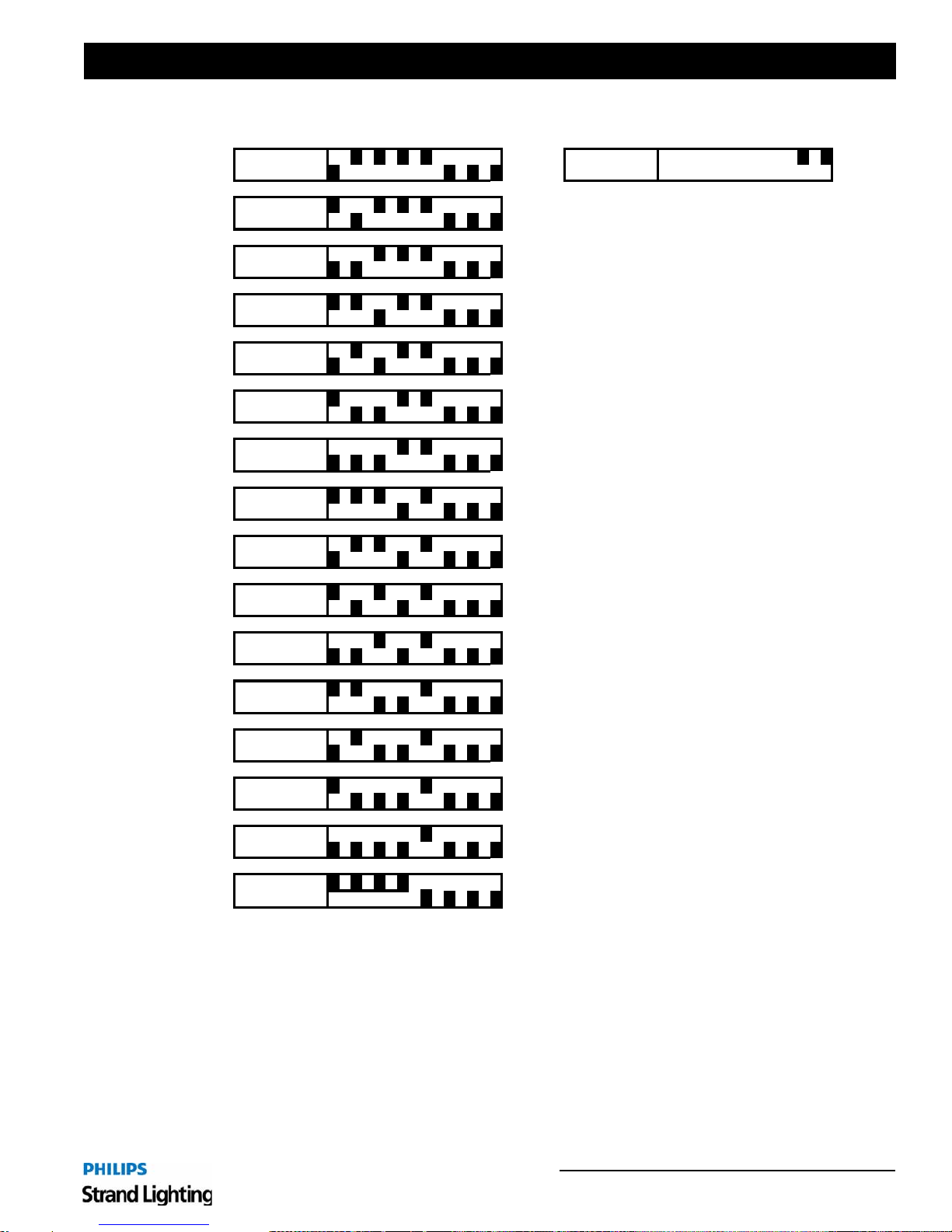
Note: Last module in network must have DIP
switches 7 and 8 set to the UP position. (All
other modules on the network have their DIP
switches 7 and 8 set to the DOWN position.)
Figure 15: Dimmer DIP Switch Setting Chart (Part 2)
R21 Powered Raceway Dimmer DIP Switch Settings 23
Page 26

Notes
 Loading...