

Strand Lighting 48/96 Manual/Memory, 24/48 Manual/Memory, 300 Series, Memory 250, Memory 125 Installation Manual
...Page 1
Welcome
Warning
Thank you for buying Strand Lighting control equipment. We hope that you
will find that your lighting needs are met by your new system and that you
will enjoy exploring the new facilities that your new system offers. You are
provided with essential information to help you install and operate your system. Please look through all the documents and keep them safely for future
use. If you have any difficulties, please do not hesitate to contact Strand
Lighting, or any authorised Strand service centre for advice.
This equipment is designed to operate from the mains electricity supply
and contains voltages which, if touched, may cause death or injury. It should
only be operated in accordance with the instructions provided and for the
purpose of a lighting control system.
Avoid spilling liquid on the equipment. If this should happen, switch the equipment off immediately. To reduce the risk of fire or electric shock, do not expose
the equipment to rain or moisture.
For indoor use only.
This equipment is designed and manufactured to comply with international safety
standards IEC950, UL1950, CS950 and is intended for use as part of a lighting
control system. It must not be used for other purposes where there is a risk of
safety to persons. The equipment contains power voltages, socket outlets shall
be installed near to the equipment and be easily accessible.
• Working Voltage/Current 100-120 (2A) 220-240 (1A)
• Frequency 50/60 Hz
• Max Ambient Temp 35
o
C
• Do not restrict ventilation
This manual describes the installation procedures for the following Strand
Lighting 300 Series consoles.
• 24/48 Manual/Memory
• 48/96 Manual/Memory
• Memory 125
• Memory 250
• Memory 400
• Memory 600
• 120 Submasters
• 310 Show Controller
Document No: 40/B973
Date: March 2000
Page 1
Installation Manual - 300 Series Consoles & 310 Show Controller
Page 2

Offices and Service Centres
Phone numbers do not include country code or other international access data.
World Wide Web: http://www.strandlighting.com/
Strand Lighting Asia Ltd: 7/F Corporation Square, 8 Lam Lok Street, Kowloon
Bay, Hong Kong.
Tel: 852 2757 3033, Fax: 852 2757 1767
E mail: [email protected]
Strand Lighting Inc (Los Angeles): 18111 Santa Fe Avenue, Ranch
Dominguez, CA 90221, USA.
Tel: (310) 637 7500, Fax: (310) 632 5519, Fax: 800 775-LEKO,
Email: [email protected]
Strand Lighting Inc (New York): 2nd Floor, 151W-25th St, New York
Tel: (212) 242 1042, Fax: (212) 242 1837,
Email: [email protected]
US Service & Support: 800 4 STRAND (800.478.7263)
Strand Lighting (Canada) Inc (Toronto): 2430 Lucknow Drive #15,
Mississauga, Ontario, L5S 1V3, Canada
Tel: 905 677 7130 or 800-387-3403, Fax: 905 677 6859, E mail:
[email protected]
Strand Lighting Limited (Kirkcaldy): Mitchelston Industrial Estate, Kirk-
caldy, Fife, KY1 3LY, Scotland,
Tel: 01592 652333, Fax: 01592 653528
Software Registration: 01592 653499, E mail:
[email protected]
Strand Lighting Limited (Paris): 1 rue de l’Arc de Triomphe, Paris 17,
France
Tel: 00 331 553 70033, Fax: 00 331 553 70233,
E mail: [email protected]
Strand Lighting GmbH (Berlin): Strand Lighting GMBH, Ullsteinstrasse
114-142, 12109 BERLIN, Tel: 004930 707 9510, Fax: 004930 707 95199
E mail: [email protected]
Strand Lighting Italia Srl - (Pomezia): Via delle Gardenie, 33, 00040
Pomezia – Roma, Italia,
Tel: 00 39 06 914 7123, Fax: 00 39 06 914 7138
E mail: [email protected]
Strand Lighting Limited (Moscow): Novinsky Boulevard 20A, Buildings 3-
6, 121069 Moscow, Russia,
Tel: 007 095 290 2092, Fax: 007 095 290
Installation Manual - 300 Series Consoles & 310 Show Controller
Page 2
Page 3
Unpacking
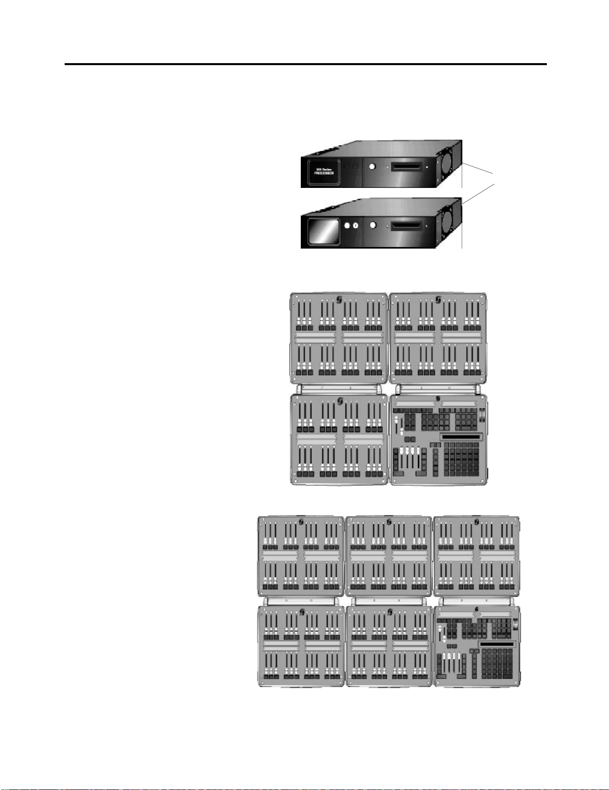
Package 1
300 Series Processor Unit, or 310
Show Controller complete with the
following:
(i) Operator’s Guide, CD Rom,
(ii) Password Disk
(iii) Power Cable
Note: The 310 Show Controller is
normally supplied as a stand-alone
lighting controller. In this case,
Package 2 is not included
Package 2
24/48 Manual/Memory console
comprising a command module
plus three fader modules.
Open the packaging and check that the following components are contained within.
If any parts are missing, or damaged, please contact the carrier and your nearest
Strand Lighting office.
300 series
Processor
Unit
or
310 Show
Controller
Mounting
Brackets
or 48/96 Manual/Memory console
comprising a command module
plus five fader modules
Page 3
Installation Manual - 300 Series Consoles & 310 Show Controller
Page 4
Unpacking
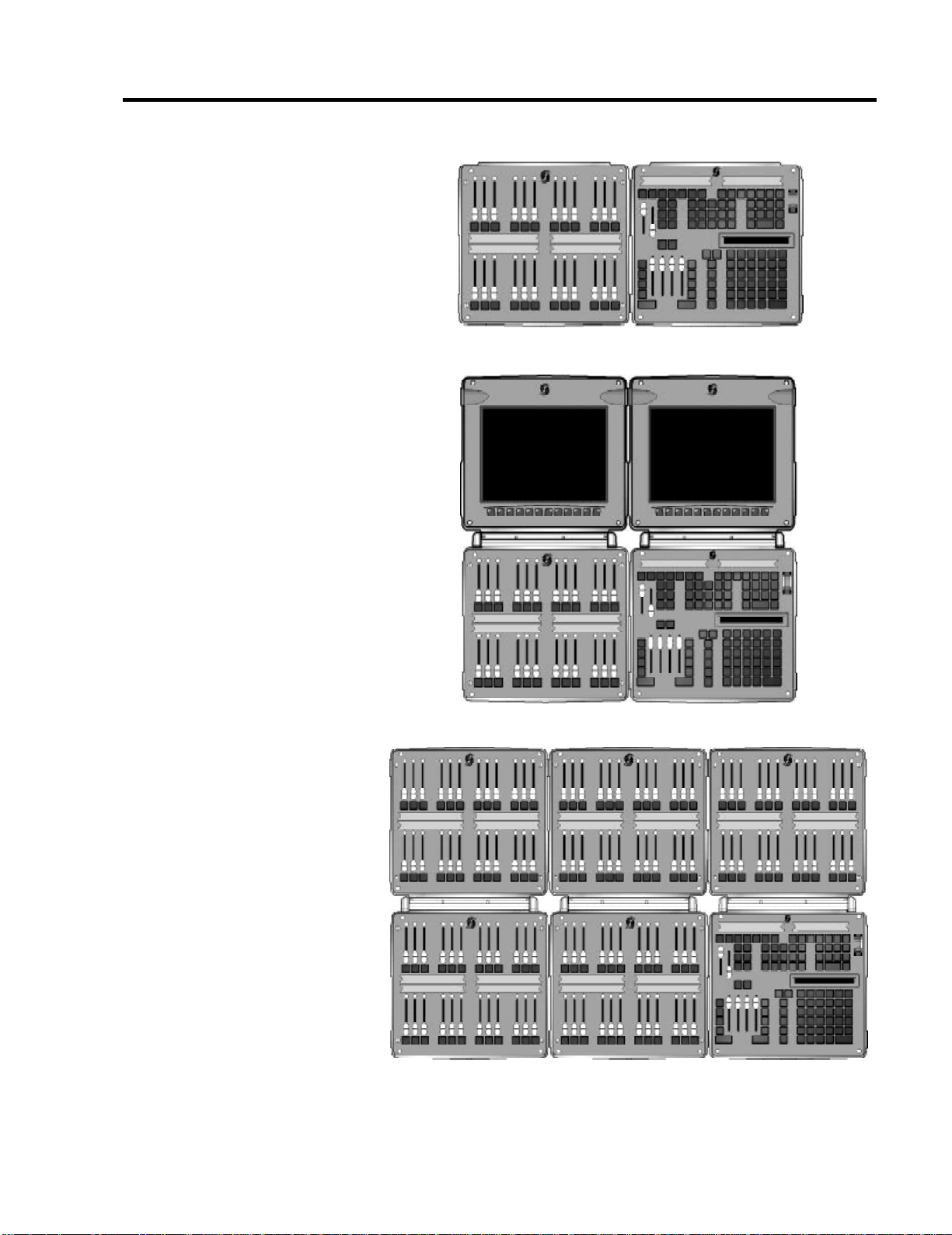
or Memory 125 or 250 console
comprising a command module
and one 24 submaster fader
module
or Memory 400 or 600 console
comprising a command module
and one 24 submaster fader
module and two LCD monitor
modules.
or 120 submaster console
comprising a command module
plus five submaster fader
modules.
and the following items:
(i) Microsoft Intellimouse trackball
(ii) LCD cables (400 and 600
Memory Consoles only)
(iii) 3 Metre Cat 5 cable with RJ45
connectors – Control Console to
Processor
Installation Manual - 300 Series Consoles & 310 Show Controller
Page 4
Page 5
Getting Started
Mounting the processor unit
(including 310 Show Controller)
Note: The equipment can be mounted
to a wall with the brackets supplied.
Ensure the fixings (e.g. wall screws) are
suitable for the weight of the unit and
are of sufficient size for the slots
provided in the back plate. The unit
can be regarded as wall mounted
moveable equipment. The means of
fastening must permit ready removal for
maintenance and repair. Therefore
after hanging the unit on its brackets,
do not tighten the screws fully, so that
the unit can be lifted from the wall.
When rack mounting, ensure that no
hazardous conditions are created due
to uneven mechanical loading.
Ensure that reliable earthing of the
equipment is maintained at all times.
Consideration should be given to the
supply circuit feeding the equipment
and the effect that overloading might
have on overcurrent protection and the
supply wiring.
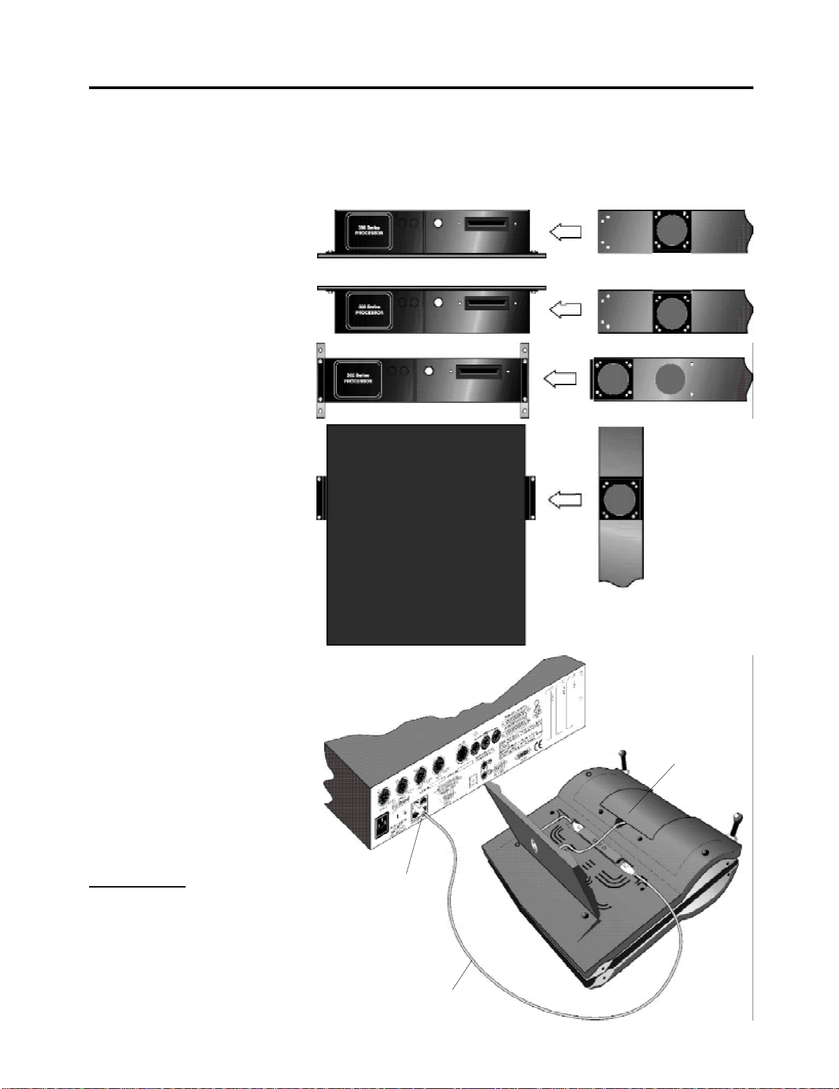
The processor unit is designed to sit on a desk, or to be mounted onto, or under
a desk, or wall-mounted, or mounted within a 19 inch rack unit. Multi-purpose
brackets are supplied with the unit as shown.
Fixed to Desk
Under Desk
Mounting
19 in Rack Unit
Fixed to Wall
Connecting The processor to the
Command Module
(Optional on 310 Show Controller)
Note: All standard models are supplied
daisy-chained with a line terminator on
the last module. Additional modules
can be added to the daisy chain, and
the line terminator moved to the last
module. Alternatively, remote modules
can be connected to one of the other
RJ45 Sbus connectors.
Important Note: Do not fit or remove
the Sbus connectors unless the console has completely powered down.
Page 5
Underside of command
module
RJ45 Sbus connector
on Processor unit
Cat 5 cable
Installation Manual - 300 Series Consoles & 310 Show Controller
Page 6
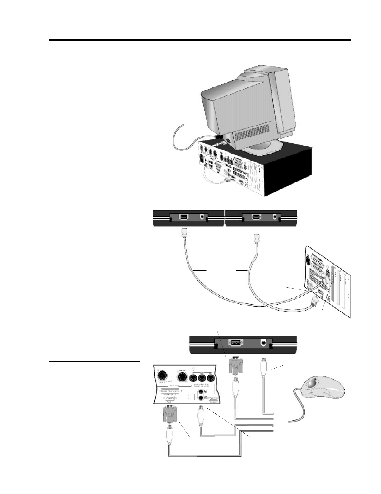
Getting Started (cont.)
Connecting an External Monitor
(Optional on 310 Show Controller
and on 400 and 600 Memory
Consoles)
Connecting LCD Monitors
(two supplied as standard on 400
and 600 Memory Consoles only)
Mains supply
Rear of
LCD Monitors
Rear of
Processor Unit
Connecting the Mouse
(Optional on 310 Show Controller)
Note: The mouse will not operate until
the mouse net node and port has
been set up in the User Setup Screen.
(Refer to the Introduction Section of
the User Guide)
Rear of
Command Module
Rear of Processor Unit
Connection to COM1
port using adaptor
LCD
Cables
Max. 10mtrs
Connection to COM2
port using adaptor
Connection to mouse PS2 port
on rear of Processor Unit
LCD1
Connector
LCD2
Connector
Connection to PS2 port
Alternative
mouse
connections
Installation Manual - 300 Series Consoles & 310 Show Controller
Page 6
Page 7
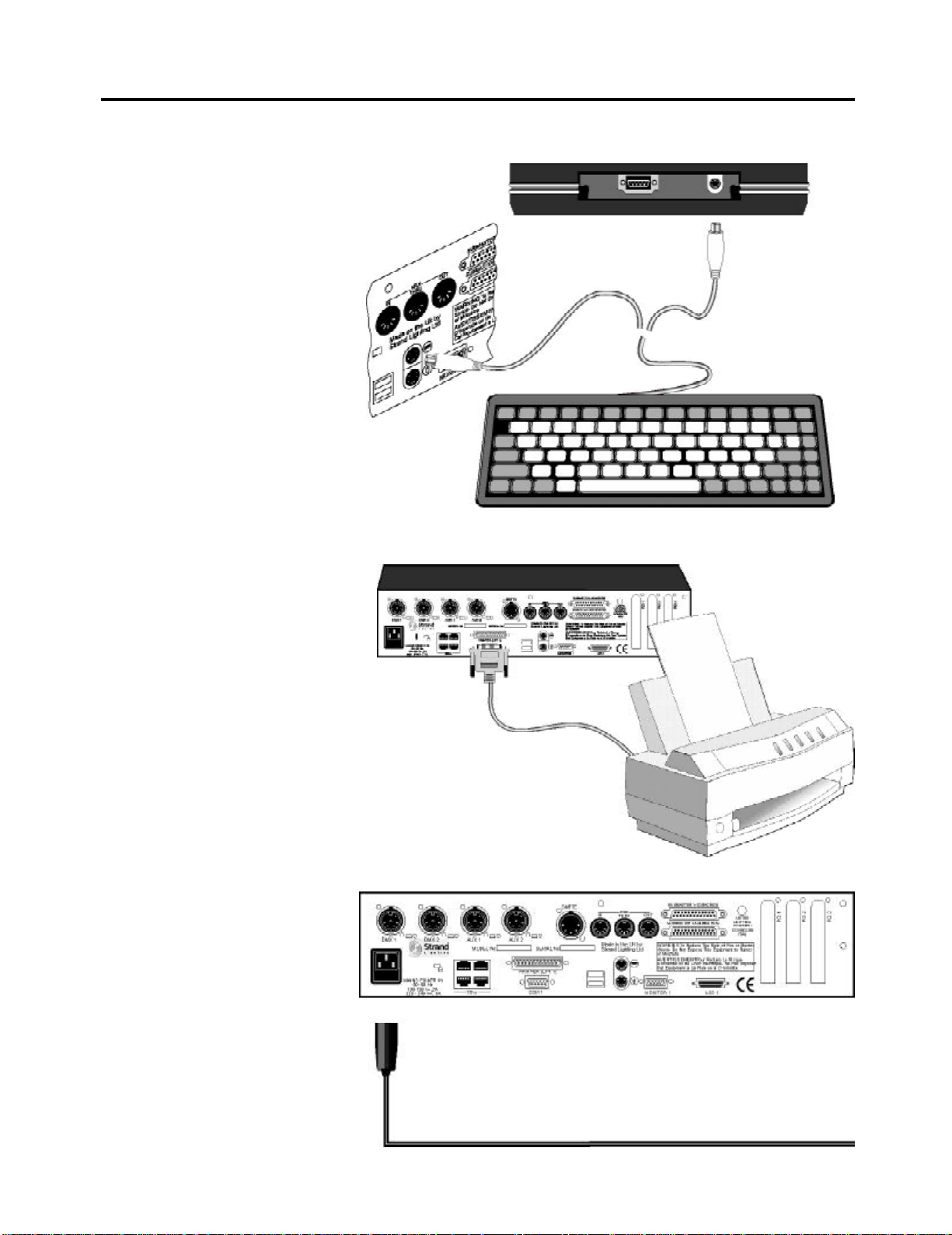
Getting Started (cont.)
Connecting an External Keyboard
(Optional)
Connecting a Printer (Optional)
Rear of
Command Module
PS2
port
Rear of
Processor
Unit
Alternative
connection to
keyboard PS2
port on rear of
Processor Unit
Keyboard
Rear of
Processor Unit
Connecting to the Mains Supply
Page 7
100 - 120, (2A) / 220 - 240V ( 1A), 50/60Hz
Installation Manual - 300 Series Consoles & 310 Show Controller
Page 8
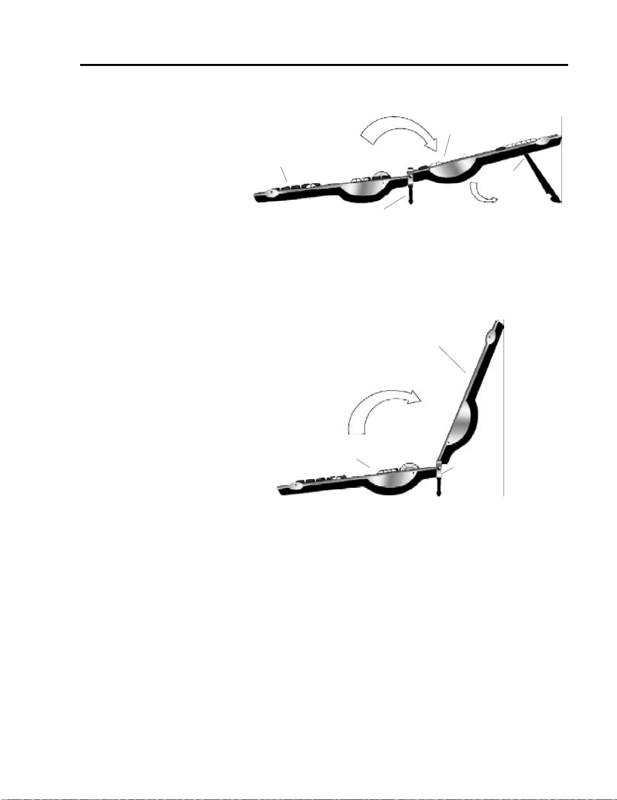
Getting Started (cont.)
Positioning Hinged Modules
Hinged fader module
Command module or
fader module
Support
Hinge
Hinged foot rest
Positioning and Support for Command Module and Fader Module, or Fader
Module and Fader Module
LCD monitor
bracket
Position for best viewing
Command module or
fader panel
Positioning and Support for Command Module and LCD Monitor module
Hinge
Hinged foot rest
Installation Manual - 300 Series Consoles & 310 Show Controller
Page 8
Page 9
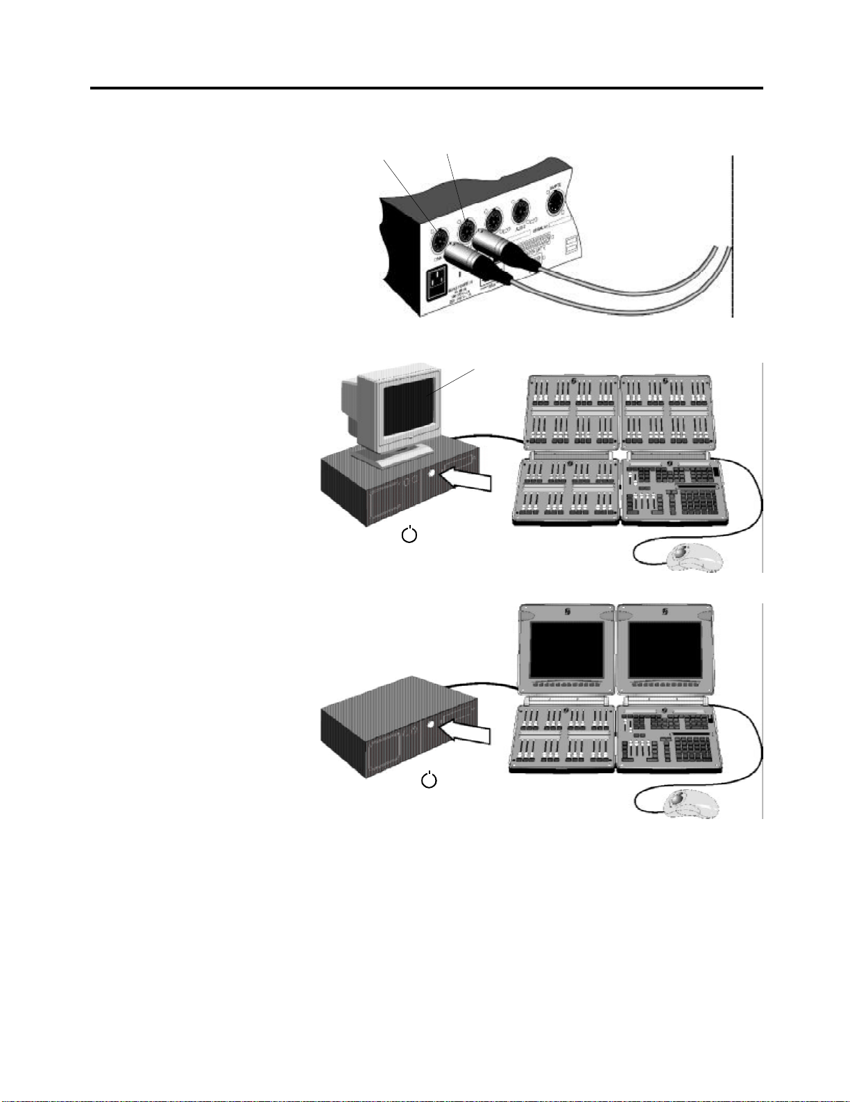
Getting Started (Cont.)
Connecting the DMX Outputs
Power Up/Power Down
Note: To shutdown, refer to the shut-
down procedure described in the User
Guide. Do not shut down by removing
the mains plug.
DMX 1 DMX 2
DMX Outputs to Dimmers,
etc. Refer to Operator’s
Manual.
Channel Level and
State Screen
Press button or ‘P14’
key on Command Module
Channel Levels
Screen
Press button or ‘P14’
key on Command Module
Operating the Lighting Consoles Operating instructions for the GeniusPro/Lightpalette software installed in your
console are provided in the Operator’s Guide supplied with this console. A
detailed operator’s manual and tutorial are also available on the CD supplied.
State Screen
Page 9
Installation Manual - 300 Series Consoles & 310 Show Controller
Page 10
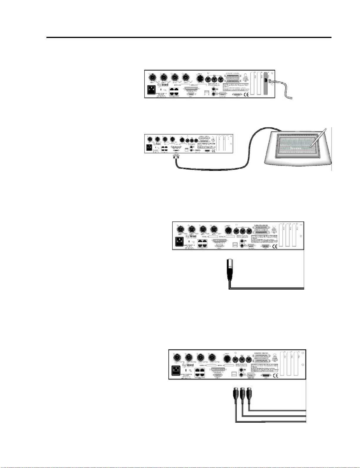
Connecting Advanced Functions of the 300 Series Consoles
Connecting to an Ethernet Network
(Standard on 310 Show Controller
and all 300 Series Memory
Consoles)
Connecting to a Macro Tablet
(Including 310 Show Controller)
Connecting a SMPTE Clock
(Standard on 310Show Controller.
Optional on 300 Series Consoles)
Rear of Processor Unit
Ethernet
connection to
network (refer to
Operator’s
Manual/
On-Screen Help)
Macro Tablet
Rear of Processor Unit
COM1port or COM2 port on
Command Module
Refer to Operator’s Guide/Manual or On-Screen Help.
Rear of Processor Unit
Connecting MIDI (Standard on
310Show Controller. Optional on
300 Series Consoles)
Refer to Operator’s Manual or On-Screen Help.
Installation Manual - 300 Series Consoles & 310 Show Controller
SMPTE clock input.
Refer to Operator’s Guide/Manual or On-Screen Help.
Rear of Processor Unit
Page 10
Page 11
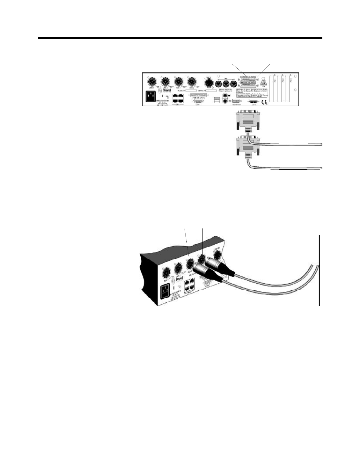
Connecting Advanced Functions of the 300 Series Consoles
Connecting External Submaster
Macros (Standard on 310Show
Controller. Optional on 300 Series
Consoles)
Connecting Hand-held Remotes
and Other Devices
(Standard on 300 Consoles and
310 Show Controller)
Submaster 1-12 Macros
External Submaster Macro
Inputs. Refer to Operator’s
Manual or On-Screen Help
Each of the 24 submaster macro inputs consist of a signal/ground pair on adjacent pins of a D type connector. The required number of contact closure devices
are coupled to the connector(s) using twisted pair cables. It is recommended to
use 24AWG twisted pair wires for each contact. CAT5 UTP cable is suitable.
AUX 1 AUX 2
Submaster 13 -24 Macros
Auxiliary Inputs for Hand-Held
Remotes and other devices. Refer to
Operator’s Manual or On-Screen
Help.
Page 11
Installation Manual - 300 Series Consoles & 310 Show Controller
Page 12
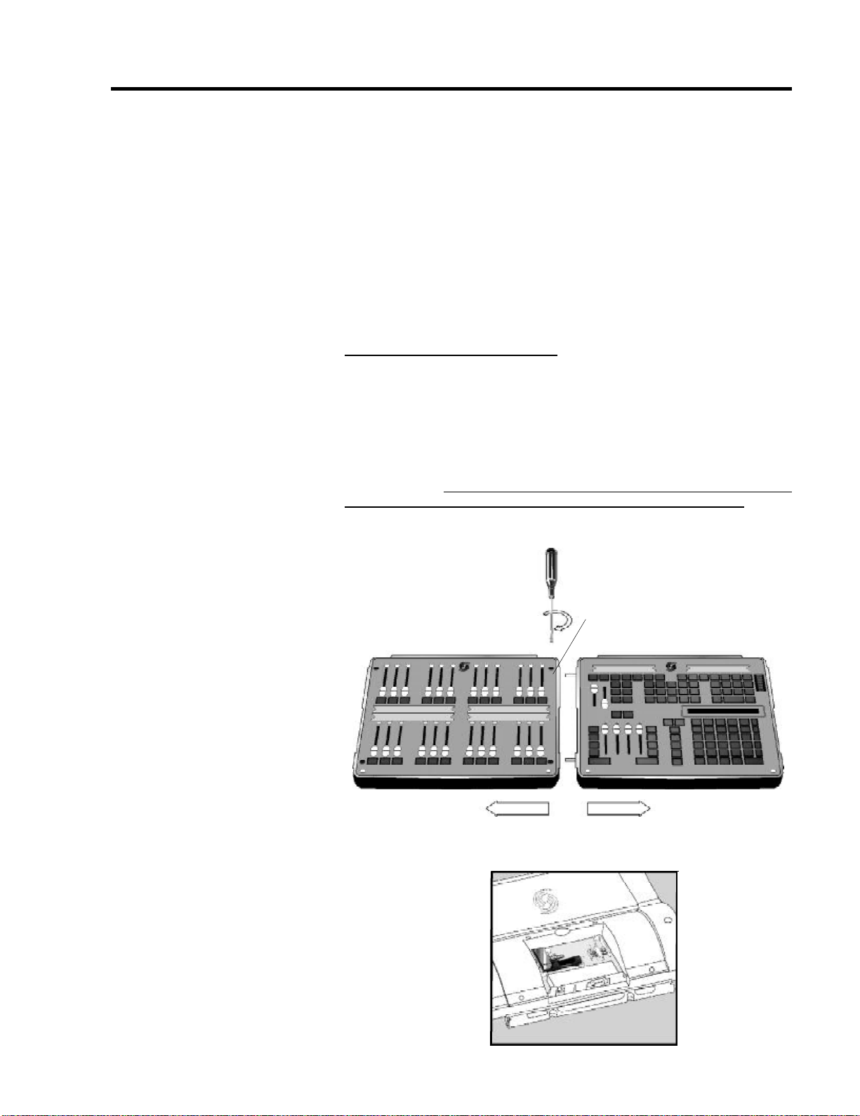
Changing the Module Configuration and Adding New Modules
Changing the Module
Configuration
The modular concept of the 300 Series consoles, allows the user to change the
configuration of modules and to add fader modules or LCD display modules as
required. Fader modules can be physically coupled to the hinge assembly, or
coupled to either side of the control module and to each other to form a
conventional control console. A maximum of two LCD modules can to be coupled
to the hinge assembly and set at the best viewing angle. You can also position
individual modules, or physically coupled modules separated by up to 100metres
from the command module.
Note: For portable units, no more than six modules should be physically connected together, (three modules on the horizontal plane and three mounted on
the hinge).
Fitting and removing a hinged module
LCD modules are always fitted to the hinge on the back of a horizontal module
and the command module always fitted as a horizontal module. However, fader
modules may be fitted in either position to suit the operator’s preference and the
layout of the control room. A hinge assembly and module coupling pins are
supplied with each module, where no module is fitted to the hinge. In this way, the
user can change the configuration of the fader modules. Similarly when additional modules are supplied, hinge assemblies and coupling pins are included.
Important Note: Before making any changes to the console configuration, ensure that the mains supply is switched off and the mains plug removed.
Before fitting or removing a hinge assembly, separate the horizontal units by turning
the two half-turn fasteners counter-clockwise and pulling the modules apart.
Screw-in module coupling pins
Screw -in pins and hinge assembly are located in the tool box on the rear of the
module, as shown.
Installation Manual - 300 Series Consoles & 310 Show Controller
Page 12
Page 13
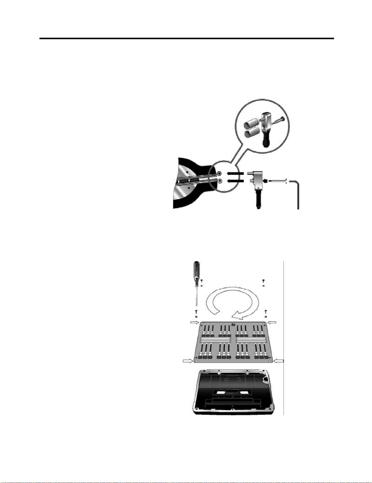
Changing the Console Configuration and Adding New Modules
Place one hinge assembly in the position shown and tighten the allen screw using the allen key provided. Place the tubed section of the module over the spigot
on the top of the hinge, ensuring that the locating pin is located in the recess, as
shown. Hold the module in position, while fitting the opposite hinge assembly. To
remove a module from the hinge, reverse this procedure.
Rotating a Fader Panel Fascia
When a fader panel is moved from a horizontal position to a hinged position, or
vice-versa, the panel fascia must be rotated such that the controls are facing the
correct way.
To rotate the panel fascia, remove the Sbus connector, then remove the four
panel screws, turn the panel facia, refit the screws and refit the Sbus connector.
Page 13
Installation Manual - 300 Series Consoles & 310 Show Controller
Page 14
Changing the Console Configuration and Adding New Modules
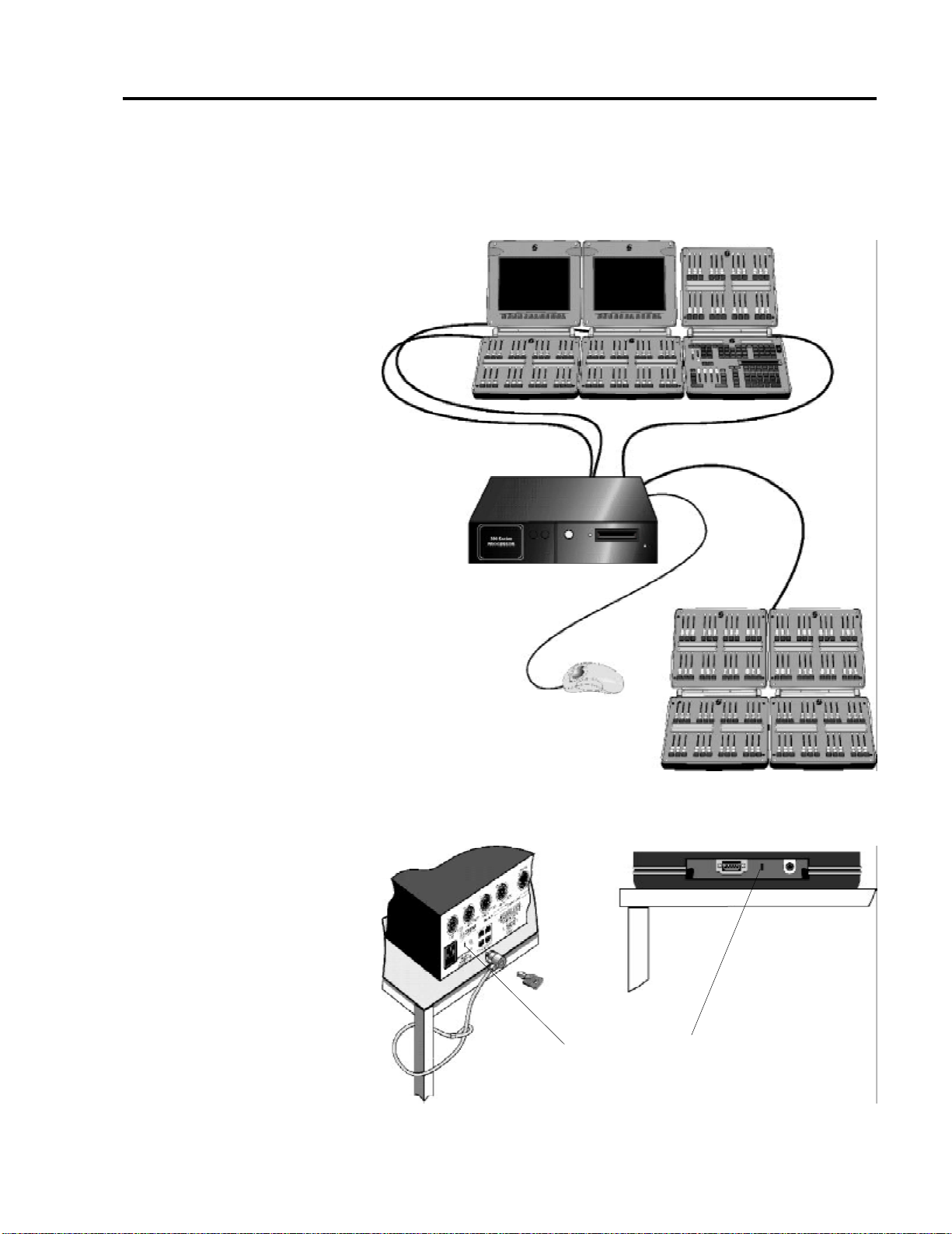
Expanding Your System
The diagram below shows a typical expanded system incorporating seven fader
panels and two LCD monitors connected to one command module and one
processor unit.
Anti-Theft Device
Installation Manual - 300 Series Consoles & 310 Show Controller
Holes for Kensington-type anti theft device
Page 14
 Loading...