

Page 1
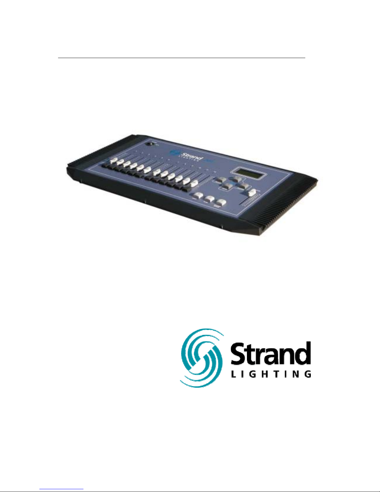
301 Console
Operations Manual
Manual
Part No. 24-004-0815
Page 2

Page 2 Strand 301 Console Manual
Welcome
Thank you for buying Strand Lighting control equipment. We hope
that you will find that your lighting needs are met by your new
system and that you will enjoy exploring the new facilities that your
new system offers. You are provided with essential information to
help you install and operate your system. Please look through all
the documents and keep them safely for future use. If you have
any difficulties, please do not hesitate to contact Strand Lighting or
any authorized Strand service center for advice.
This equipment is designed to operate from the mains electrical
supply and contains voltages, which, if touched, may cause death
or injury. It should only be operated in accordance with the
instructions provided and for the purpose of a lighting control
system.
Do not open the console. There are no user serviceable parts
inside.
Avoid spilling liquid on the equipment If this should happen, switch
the equipment off immediately. To reduce the risk of fire or electric
shock, do not expose the equipment to rain or moisture.
For indoor use only.
This equipment is designed and manufactured to comply with
international safety standards 1EC950, UL1950, CS950 and is
intended for use as part of a lighting control system. It must not be
used for other purposes where there is a risk of safety to persons.
The equipment contains power voltages, socket outlets shall be
installed near to the equipment and be easily accessible.
• Working Voltage/Current 100-120 (2A) 220-240 (1A)
• Frequency 50/60 Hz
• Max Ambient Temp 35
0
C
• Do not restrict ventilation
This manual describes the installation and operational procedures
for Strand Lighting’s 301 Control Console
.
Page 3

Strand 301 Console Manual Page 3
Offices and Service Centers
Please confirm all country codes or other international access data.
World Wide Web: http://www.strandlighting.com/
Berlin
Strand Lighting GMBH
Ullsteinstrasse. 114-142, HAUS C
D-12109
Berlin, Germany
Tel. +49-30-707-9510 Fax +49-30-707-95199
Hong Kong
Strand Lighting Asia LTD
20/F., Delta House
3 On Yiu Street
Shatin, N.T.
Hong Kong
Tel. +852-2757-3033 Fax +852-2757-1767
London
Strand Lighting Limited
Unit 3 Hammersmith Studios
Yeldham Road
Hammersmith
London, England W6 8JF
Tel. +44-20-8735-9790 Fax +44-20-8735-9799
Los Angeles
Strand Lighting Inc
6603 Darin Way
Cypress, CA 90630
U.S.A.
Tel. +1 714-230-8200 Fax +1 714-230-8173
Moscow
Strand Lighting
Novinsky Boulevard 20A Building 3-6
12069 Moscow, Russia
Tel. +7 095-234-42-20 Fax. +7 095-234 42-21
Rome
Strand Lighting Italia
Via Delle Gardenie S.N.C.
Pontina Vecchia KM 33,400
00040 Pomezia, Italy
Tel. +39-0691-9631 Fax +39-0691-47138
Toronto
Strand Lighting (Canada) Inc
2430 Lucknow Drive #15,
Mississauga, Ontario, L5S 1V3
Canada
Tel. +1 905-677-7130 Fax. +1 905-677-6859
Page 4

Page 4 Strand 301 Console Manual
Table of Contents
Welcome................................................................................................................................. 2
Offices and Service Centers................................................................................................... 3
Table of Contents.................................................................................................................... 4
Getting Started........................................................................................................................ 6
Concept............................................................................................................................... 6
Ordering Information........................................................................................................... 6
Mechanical & Environmental Data...................................................................................... 6
Standards Compliance........................................................................................................ 6
Unpack the Console............................................................................................................ 6
Face Plate...........................................................................................................................7
Back Plate...........................................................................................................................7
Layout..................................................................................................................................... 8
Quick Guide............................................................................................................................ 9
Setup..................................................................................................................................... 11
Rack Mounting.................................................................................................................. 12
Operation.............................................................................................................................. 13
Basic Navigation ............................................................................................................... 13
Changing Modes............................................................................................................... 13
Back up Mode................................................................................................................... 14
Capacity........................................................................................................................14
Changing Modes........................................................................................................... 14
Screen Menus for Back up............................................................................................ 14
Main Screen -............................................................................................................ 14
Menu -....................................................................................................................... 15
- Delete Scene....................................................................................................... 15
Delete One Scene............................................................................................. 15
Delete Page Scene ........................................................................................... 15
Delete All Scenes.............................................................................................. 16
- Set Buzzer........................................................................................................... 16
- Set Clock............................................................................................................. 16
Cross Fade Time –.................................................................................................... 17
Recording of Back Up Scenes...................................................................................... 17
Change Pages -........................................................................................................ 18
Playback of Back Up Scenes........................................................................................ 18
- Back Up Cues on Multiple Pages ........................................................................... 19
Flash ......................................................................................................................... 20
Page 5

Strand 301 Console Manual Page 5
Timed Events Mode.......................................................................................................... 21
Capacity........................................................................................................................21
Changing Modes........................................................................................................... 21
Screen Menus for Events Player................................................................................... 21
Main Screen -............................................................................................................ 21
Menu -....................................................................................................................... 21
- Delete Event........................................................................................................ 22
Delete One Event.............................................................................................. 22
Delete All Events............................................................................................... 22
- Set Default Fade Time........................................................................................ 22
- Set Buzzer........................................................................................................... 23
- Set Clock............................................................................................................. 23
Recording of Timed Events........................................................................................... 23
Manual Playback of Timed Events................................................................................ 24
Scheduling Playback of Timed Events.......................................................................... 24
Starting the Timed Events............................................................................................. 25
12 Channel Control Mode................................................................................................. 27
Capacity........................................................................................................................27
Changing Modes........................................................................................................... 27
Screen Menus for 12 Channel Control.......................................................................... 27
Main Screen -............................................................................................................ 27
- Cross Fade Time (XFtm)..................................................................................... 27
- Patch................................................................................................................... 28
Edit Patch.......................................................................................................... 28
Display Patch .................................................................................................... 29
Default Patch..................................................................................................... 29
One Scene Mode.......................................................................................................... 30
Hold – Two Scene Mode............................................................................................... 30
Multiple Units .................................................................................................................... 31
Capacity........................................................................................................................31
Setup............................................................................................................................. 31
Operation ...................................................................................................................... 32
Analogue Input Operation................................................................................................. 32
Conclusion............................................................................................................................ 33
Accessories........................................................................................................................... 33
Appendix A............................................................................................................................ 34
Control Input ..................................................................................................................... 34
Link Input .......................................................................................................................... 34
Analogue In....................................................................................................................... 34
Index.................................................................................................................................35
Page 6

Page 6 Strand 301 Console Manual
Getting Started
Concept
The 301 series console provides 3 modes of operation. Back up, Timed Events,
and 12 Channel Control mode. Back up mode provides cue storage of 144 look s
or cues to any DMX512 based lighting console for one universe of DMX512.
Timed Event mode provides recording and playback for 12 timed events via the
system clock. The events can be played back in any order . 12 Channel Control
mode provides 1 scene 12 channel mode with patch for 512 dimmers. Two
scene operation can be enables with the hold button. This console ca n be rack
mounted
Ordering Information
Catalog #95713 – 301 Back up control system 120 volt
Catalog #91713 – 301 Back up control system 230/240 volt
Catalog #24-004-0815 – 301 console manual
Mechanical & Environmental Data
Weight: 4 kg
Finish: Blue powder coat epoxy paint
Construction: Rigid folded sheet steel
Temperature: 0 – 35°C
Humidity Range: 0-90% non-condensing
Ingress Protection: IP20
Standards Compliance
All units are CE marked. 120 volt consoles include UL, cUL power supplies.
Unpack the Console
Unpack the console from the packaging and check that the following components
are contained within. If any parts are missi ng, or damaged, please contact the
carrier and your nearest Strand Lighting office.
List of Parts for North America…
(1) 301 series console
(1) Power cable with UL power supply cable with US 2 pin connector
(1) Manual
(1) Vinyl Dust Cover
List of Parts for Europe and Asia…
(1) 301 series console
(1) Power cable with cUL power supply cable with
(1) UK 2 pin connector and EU 3 pin connector
(1) Manual
(1) Vinyl Dust Cover
Page 7
Strand 301 Console Manual Page 7
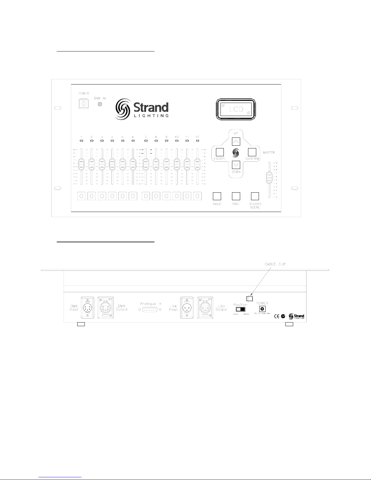
Face Plate
Back Plate
301
Page 8
Page 8 Strand 301 Console Manual
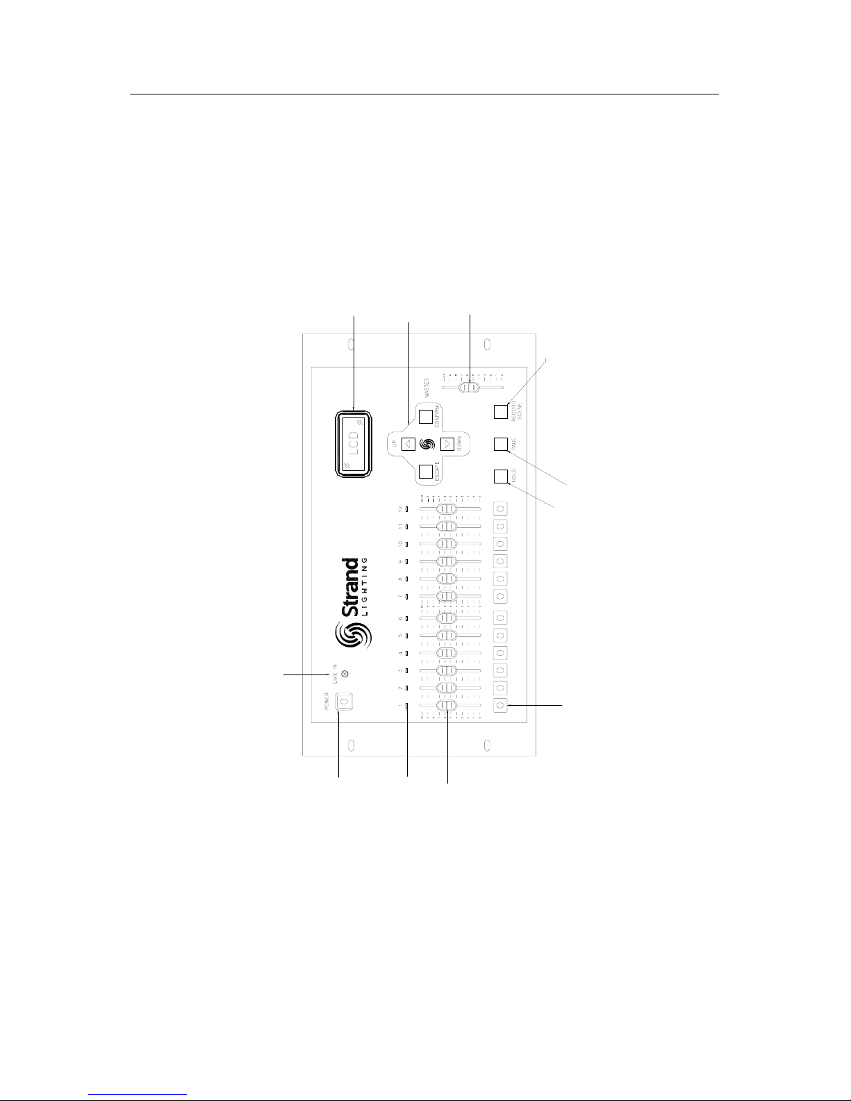
Layout
301
11. POWER SWITCH
10. DMX IN INDICATOR
4. FLASH BUTTONS
3. FADERS
5. HOLD BUTTON
6. PAGE BUTTON
7. RECORD SCENE BUTTON
1. MASTER
2. NAVIGATION BUTTONS
8. LCD SCREEN
9. LED INDICATORS
Page 9

Strand 301 Console Manual Page 9
Quick Guide
1. Master– an inhibitive fader that proportionately controls all other faders. This determines
maximum output of all faders at all times. The master is always active.
2. Navigation Keys– these keys allow access to all setup and mode change functions.
Up – the function of this key will be displayed at the bottom center of the LCD screen
to the left of the slash (/). It often allows the cursor to move up any list on the LCD
display.
Down – the function of this key will be displayed at the bottom center of the LCD
screen to the right of the slash (/). It often allows the cursor to move down any list on
the LCD display.
Escape – the function of this key will be displayed at the bottom left of the LCD
screen. It often allows the console to cancel a command.
Confirm - the function of this key will be displayed at the bottom right of the LCD
screen. It often allows the console to accept a command.
3. Channel Faders – a fader that controls the output of the patched dimmer number.
4. Flash Buttons – these change functions according to the mode of the console.
In back up mode – a momentary button that flashes the level of the corresponding
scene to full.
In timed event mode – to enter into event setting.
In manual mode - a momentary button that flashes the level of the corresponding
fader to full.
5. Hold Button– this button will freeze the output of the faders so that the operator can reset
the channel faders for a different look.
6. Page– changes function according to the mode of the console.
In back up mode – changes from page 1 through 12 for playback and recording of
cues.
In timed event mode – the page button is inactive.
In manual mode – the page button is inactive.
Page 10

Page 10 Strand 301 Console Manual
7. Record Scene– changes function according to the mode of the console.
In back up mode – allows the recording of back up cues from the main lighting
console. 144 back up cues can be recorded. (12 pages of 12 cues each.)
In timed event mode – allows the recording of timed events. 12 timed events can be
recorded. Timed events can be played back in any order.
In manual mode – the record scene button is inactive.
8. LCD Screen – displays current information about the console’s mode and fader status.
9. LED Indicator Lights – display relative brightness when the fader below it is active.
10. DMX IN Indicator – the LED is illuminated when the console is in either back up or event
player mode AND it is receiving DMX from the main console. The LED flashes when DMX is
not being received.
11. Power Switch – turns on / off power to the console.
DMX Input – accepts a DMX512 5 pin XLR connector from the DMX512 output of the main
console.
DMX Output – accepts a DMX512 5 pin XLR connector from the dimmers.
Analogue In – accepts an analogue input for 12 contact closures.
Link Input – as a master 301 console, accepts a DMX512 3 pin XLR connector from the
Link Output of the slave 301 console.
Link Output – as a slave 301 console, accepts a DMX512 3 pin XLR connector from the
Link Input of the master 301 console.
Console Position Switch – sets the console to either master or slave mode.
Power Connector – accepts the power adaptor from the power transformer.
Page 11
Strand 301 Console Manual Page 11
Setup
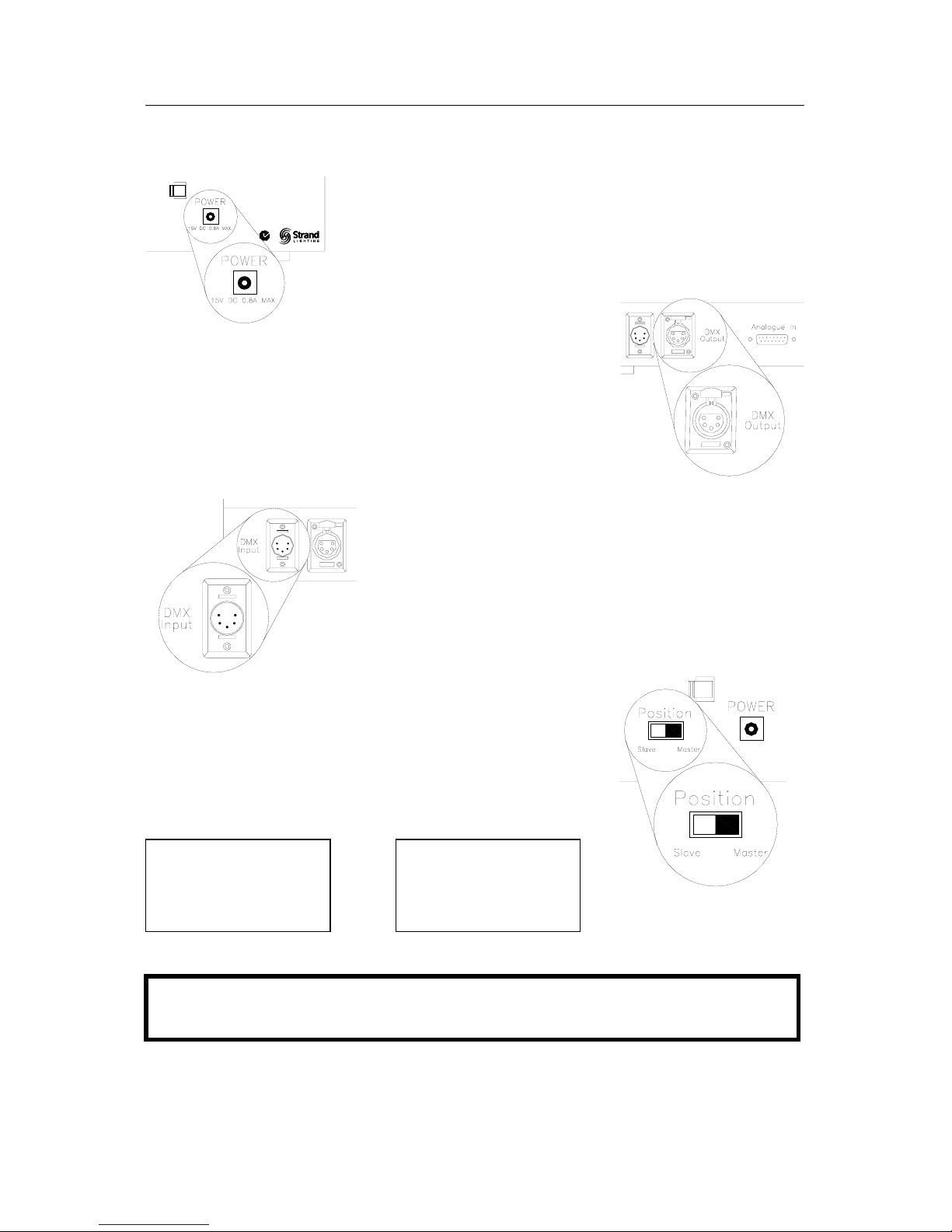
Plug the appropriate power adaptor into the console where
shown. Plug the male end into the appropriate electrical service.
Plug the DMX512 cable from the dimmer rack into the DMX512
output of the 301 console.
This may already be attached to the DMX512 output of the
lighting system’s main lighting console. The DMX512 output to
the lighting system needs to run to the 301 first. This will allow
the 301 to send the back up cues to the dimmers should the
main console fail.
Plug a DMX512 cable from the main lighting console’s first
DMX output to the DMX512 input of the 301.
This DMX512 universe will be captured during back up
recording of cues.
Make sure the Master / Slave switch is set to master.
If this is correct, once the console is on, no matter what mode
the console is in, at the center of the bottom line on the LCD
screen, it will say <Ms> for master. If in slave mode, it will show
<sl> for slave.
<Ms>
<sl>
Important Note: Before connecting the console up, please remove the protection
sheet for the back-up battery, which is located at the bottom of the console.
Page 12
Page 12 Strand 301 Console Manual
For multiple unit setup, see Multiple Units – Setup section in this manual.
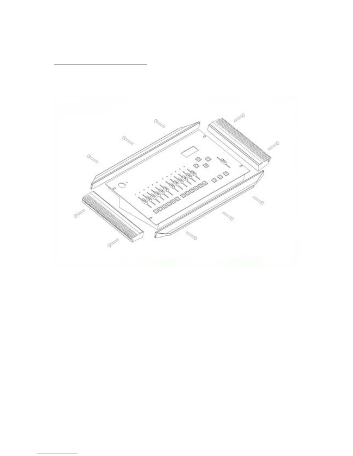
Rack Mounting
Below is a drawing that illustrates the removal of the edge pieces for rack mounting.
Page 13
Strand 301 Console Manual Page 13
Operation
Basic Navigation
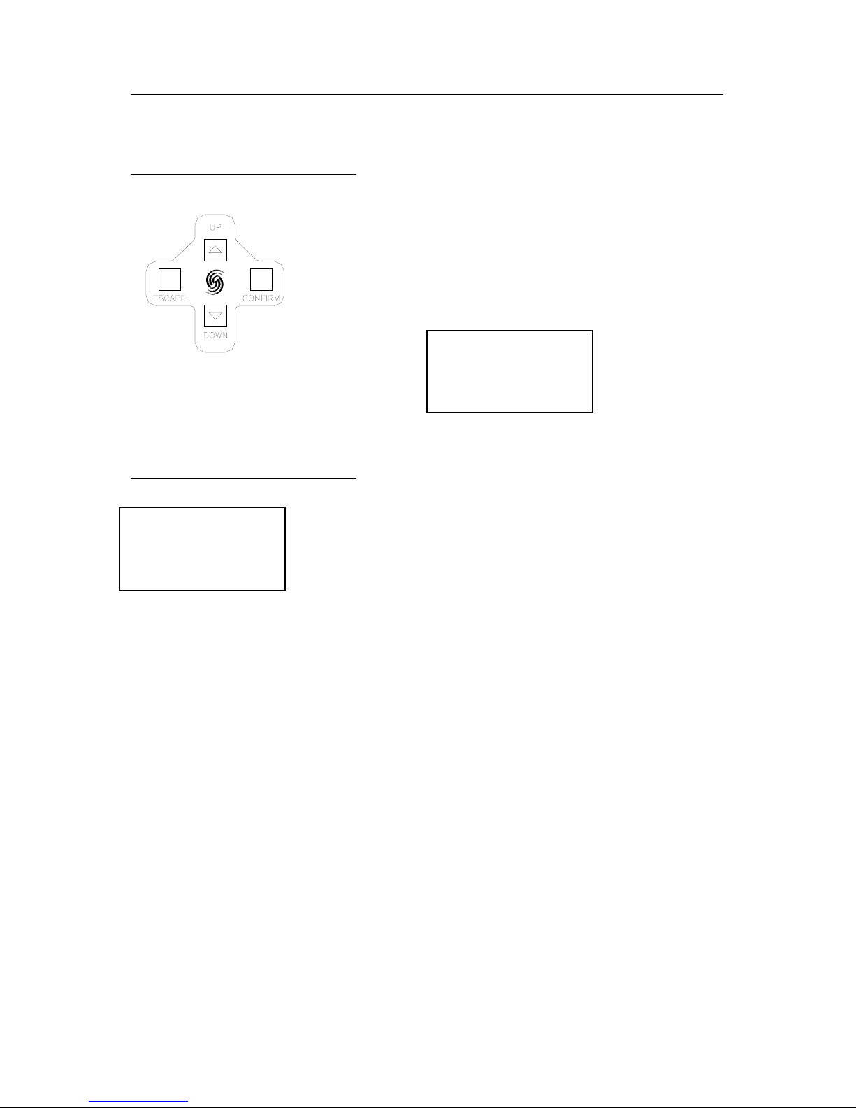
Basic navigation for the 301 is done with four buttons
(represented to the left). The functions of the keys are labeled
on the bottom line of the LCD screen. Escape on the left,
Confirm on the right and Up / Down in the center separated by
a slash (/). With the example below, Escape = Quit, Up/Down
scroll through options 1, 2 and 3. Confirm = Confirm.
Changing Modes
To change modes, hold down BOTH the up and down keys
simultaneously for 3 seconds. A list will appear on the LCD
screen.
Navigate with the up and down keys to pick the appropriate mode.
Notice the flashing cursor on the current selection. When the
cursor is on the appropriate mode, press Confirm to accept.
1. Back Up
2. Events Player
3. 12 Ch Control
Quit +/- Confirm
1. Back Up
2. Events Player
3. 12 Ch Control
Quit +/- Confirm
Page 14
Page 14 Strand 301 Console Manual
Back up Mode
Capacity
The 301 can record up to 144 cues for a full universe of DMX. 12 pages at 12 cues per
page. (A universe is defined as 512 DMX outputs)
More that one universe can be captured but that requires multiple units. (See the Multiple
Unit section for more information.)
Changing Modes
To change modes, hold down BOTH the up and down keys
simultaneously for 3 seconds. A list will appear on the LCD
screen.
Navigate with the up and down buttons to pick the appropriate
mode. Notice the flashing cursor on the current selection. When
the cursor is on the appropriate mode, press Confirm to accept.
The first time the console is powered up, it defaults to back up mode.
Screen Menus for Back up
Main Screen -
This is the back up mode’s main screen menu.
Information on this screen is as follows…
Time – console’s internal time clock.
Page – shows the active page for back up cues.
C-Page – (Current Page) this shows the console’s current back up
page. (XX indicates there is no content on last actioned fader.)
Ch – this indicates the channel that had the last action.
Level – this indicates the last action channel’s level.
XFtm – Timed Cross Fade. This allows the operator to change the default cross fade time
using the +/- keys.
<Ms> - this lets the operator know that the console is in master mode rather than slave
mode. With a single 301, this should always be Ms.
Menu – allows the operator to adjust setup options and delete items specific to the current
mode.
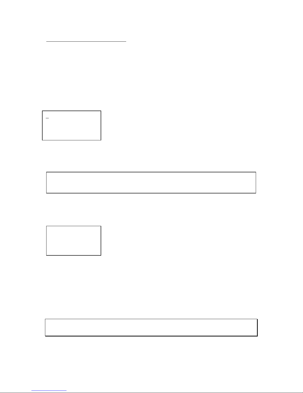
Note: If the console displays <Ms-f> this means there are more than one conso le in the back up chain
have been set to master mode. Check the master/slave switch and make sure only one co nsole is set
as master and the rest as slave.
12:00:00 Page:01
C-Page:XX Ch:01
Level:00
XFtm <Ms> Menu
1. Back Up
2. Events Player
3. 12 Ch Control
Quit +/- Confirm
Note: if there are channels that are active and the 301 is changed from back up mode to
12 channel control mode, the console can only control channels 1 – 12 according to its
p
atch. All other outputs will be ignored.
Page 15
Strand 301 Console Manual Page 15
Menu -
Menu – this allows access to the back up menu that deletes scenes, sets the buzzer and
clock.
Delete Scene – gives the operator the delete scene options.
Set Buzzer - allows the operator to either Enable or Disable the
buzzer.
Set Clock – allows the operator to set the internal clock.
- Delete Scene
Delete
One Scene
Delete One Scene – deletes a single scene on a single page.
Navigate using the up
and down keys to select
the page and then press
one of the flash button to
select scene to delete.
Then press Confirm.
(The XX represents the item number)
Delete
Page Scene
Delete Page Scene – deletes all scenes on a single page.
Navigate using the up
and down keys to select
the page to delete. Then
press Confirm.
Note: When an entire page of scenes are deleted, the console automatically advances to the next
page number for quick deletion of the next page. Also, when the console is back in playback mode,
the console has advanced to these pages live.
1. Delete Scene
2. Set Buzzer
3. Set Clock
Quit +/- Confirm
1. Del One Scene
2. Del Page Scene
3. Del All Scene
Quit +/- Confirm
Del One Scene
Page: XX
Scene: XX
Quit +/- Confirm
1. Del One Scene
2. Del Page Scene
3. Del All Scene
Quit +/- Confirm
Del Page Scene
Page: XX
Quit +/- Confirm
Page 16
Page 16 Strand 301 Console Manual
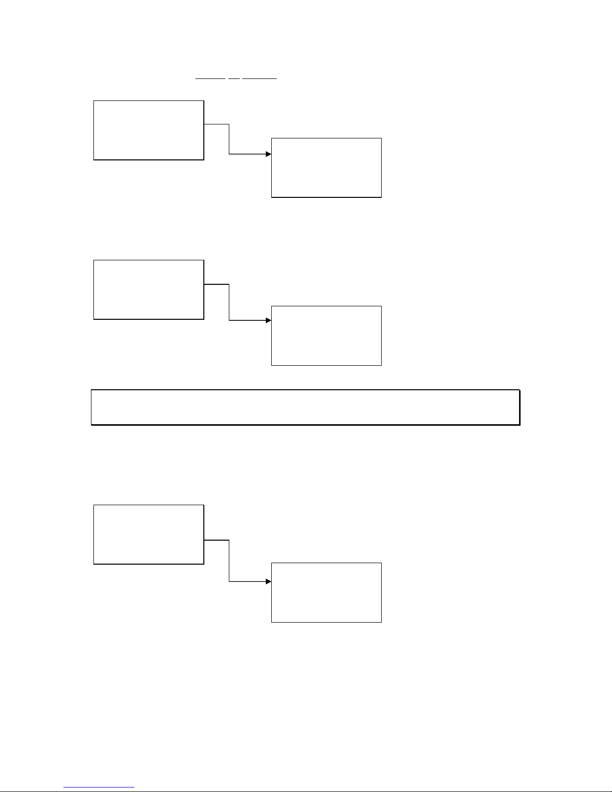
Delete
All Scenes
Delete All Scenes – deletes all scenes on all pages.
Press Confirm to
complete the deletion.
- Set Buzzer
Set Buzzer – The buzzer indicates if the back up has lost the
DMX512 signal. The options are Enable and Disable. There is no
other indication of the buzzer’s status.
Navigate using the up
and down keys to select
the buzzer option. Then
press Confirm.
Note: When DMX is lost, the buzzer will sound (if enable) and the DMX IN LED will flash until DMX is
restored to the main lighting console. The buzzer will also turn off automatically if any action is taken
on the console subsequent to DMX loss.
- Set Clock
Set Clock – this allows the operator to set the internal clock of the
console. The time is displayed in 24 hour mode. The console will
automatically go back to the main screen after 5 seconds of
inactivity.
Navigate using the left
key. Set the time using
the up and down keys.
Then press Confirm.
1. Del One Scene
2. Del Page Scene
3. Del All Scene
Quit +/- Confirm
Delete All Scene
Are You Sure?
Quit Confirm
1. Delete Scene
2. Set Buzzer
3. Set Clock
Quit +/- Confirm
Buzzer Set
1. Enable Buzzer
2. Disable Buzzer
Quit +/- Confirm
1. Delete Scene
2. Set Buzzer
3. Set Clock
Quit +/- Confirm
Set Clock
TIME:12:00:00
> +/- Confirm
Page 17
Strand 301 Console Manual Page 17
Cross Fade Time –
Cross fade time – represented by (XFtm) allows you to set the
default cross fade time. Time can be any value from 0 – 99
seconds.
(The navigation keys do wrap from 0 to 99).
Navigate using the up
and down keys to select
the default time. Then
press Confirm.
Recording of Back Up Scenes
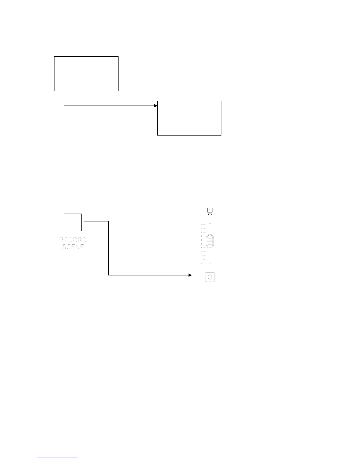
Once the consoles are setup properly to record a back up cue as page 1 scene 1, just
advance to the cue on the main lighting console, hold down the Record Scene button and
press the Flash button that corresponds with fader 1.
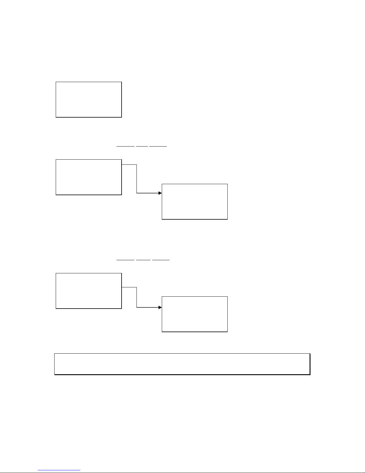
This will capture the current cue from the main lighting console.
Hold down while pressing
All LEDs will flash momentarily. When recorded, the LED above the selected fader will light
up.
The process can be repeated until all 12 faders have a cue stored in each one. For more
than 12 cues, change to a different page.
CrossFade Time
05 Sec
+/- Confirm
12:00:00 Page:01
C-Page:XX Ch:01
Level:00
XFtm <Ms> Menu
Page 18
Page 18 Strand 301 Console Manual
Change Pages -
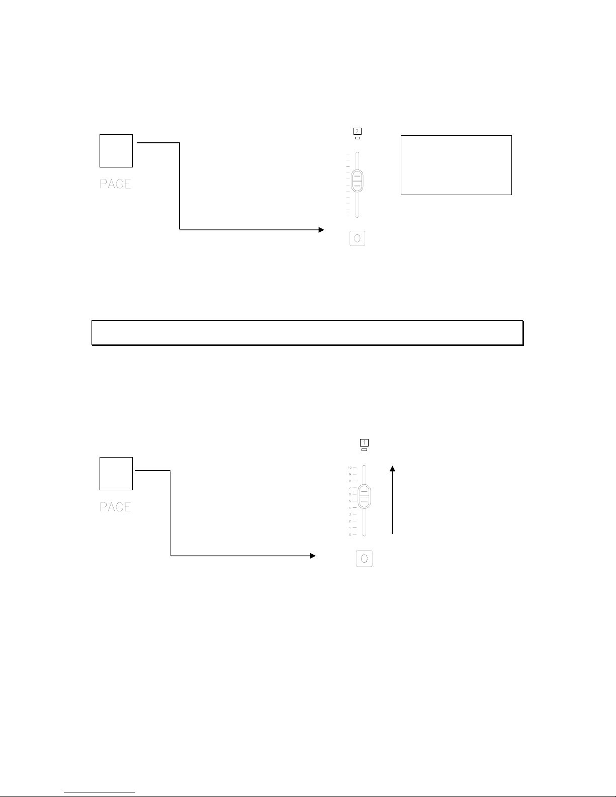
To change pages, hold down the Page button and press the Flash button that corresponds
with the page that is required. For example, to change to page 2…
Hold down while pressing
This will change the console to page 2. The LCD screen will list the page in the upper right
hand corner. Notice the LEDs that were illuminated over the faders that have been
recorded have gone out. This indicates that there are no recorded scenes on page 2.
Note: If no faders have been activated yet, the C-Page will still show the last active page. The C-page
will display XX if the last actioned fader is empty.
Playback of Back Up Scenes
To play the back up cues, just change to the appropriate page and give a level to the
appropriate fader. For example, change to page one and activate fader one.
Activate fader one.
Hold down while pressing
Notice that the Current Page doesn’t change until you activate the first fader after changing
pages. This keeps any active faders on the previous page from deactivating while they have
a level. Read more about Non-Current Page Active Faders in the Operation section below.
Recording scenes as back up cues from the main lighting console on the 301 is quick and
simple. But there are a few things to know when dealing with multiple pages.
12:00:00 Page:02
C-Page:XX Ch:01
Level:00
XFtm <Ms> Menu
Page 19
Strand 301 Console Manual Page 19
- Back Up Cues on Multiple Pages
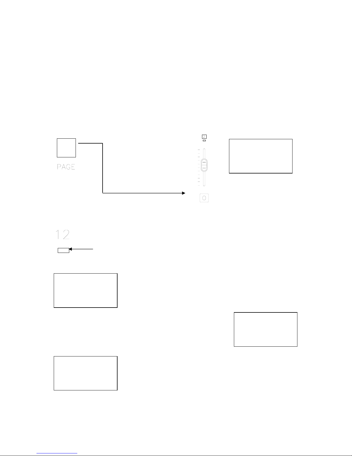
It’s very common to need to crossfade from a back up cue on one page to a back up cue on
another page. The example below will show how to go from page 1 fader 12 to page 2 fader
1.
First, make sure that there are back up cues recorded on page 1 fader 12 and page 2 fader
1. Then change to page 1 and take fader 12 to full.
If necessary, see Record Mode and Change Pages above.
With page 1 fader 12 live on stage, change to page 2.
Hold down while pressing
The console is now on page 2 while the current page is page 1 because page 1 still has an
active fader. The active fader is listed as Ch:12 on the LCD screen with the level at full.
Notice that the LED above fader 12 is flashing indicating that it is still active.
This is a Non-Current Page Active Fader.
The Current Page will display XX until a fader is moved on the new
page 2.
Once fader 1 is active, the fader will be listed as Ch:01
and the intensity as Level:FL.
As soon as fader 12 (the one that has a flashing LED) is activated,
the page is was from, channel and level will appear on the LCD
screen. When the fader goes to zero, the LED light will go out,
indicating that this scene is no longer being held on this fader from
the previous page (page 1).
12:00:00 Page:02
C-Page:01 Ch:12
Level:FL
XFtm <Ms> Menu
12:00:00 Page:02
C-Page:XX Ch:12
Level:00
XFtm <Ms> Menu
12:00:00 Page:02
C-Page:02 Ch:01
Level:FL
XFtm <Ms> Menu
12:00:00 Page:02
C-Page:01 Ch:12
Level:50
XFtm <Ms> Menu
Page 20

Page 20 Strand 301 Console Manual
Note: When the same faders are used on multiple pages and a scene is active from a previous fader,
that fader will not release the active scene until the fader is taken to zero. Then it will automatically
reload the scene from the current page. This will be indicated by C-Page info on the LCD screen and
the LED above the fader changing from flashing to being constantly on.
Flash
Any scene that is recorded can be flashed momentarily by pressing and releasing the flash
button below the appropriate fader.
Page 21
Strand 301 Console Manual Page 21
Timed Events Mode
Capacity
There are 12 timed events that can be recorded. The events are triggered using the internal
system clock. Timed events may be played back in any order.
Changing Modes
To change to timed event mode, hold down BOTH the up and
down keys simultaneously for 3 seconds. A list will appear on the
LCD screen.
Navigate with the up and down keys to pick the Events Player.
Notice the flashing cursor on the current selection. When the
cursor is on the appropriate mode, press Confirm to accept.
Screen Menus for Events Player
Main Screen -
This is the event player mode’s main screen menu.
Information on this screen is as follows…
Time – console’s internal clock. (Can be set in the Menu.)
Event Stop – this indicates that no event is currently running.
Ch – this indicates the channel that had the last action.
LL – this indicates the last action channel’s level.
Start - this button will allow the console to start the next scheduled event.
<Ms> - this lets the operator know that the console is in master mode rather than slave
mode. With a single 301, this should always be Ms.
Menu – allows the operator to adjust setup options and delete items specific to the current
mode.
Menu -
Menu – this allows access to the event player menu that deletes events, sets default fade
time and sets buzzer and clock.
Delete Event – gives the operator the delete event options.
Set Default Fade Time – allows the operator to set the default fade
time. (The maximum is 59:59)
Set Buzzer - allows the operator to either Enable or Disable the
buzzer.
There is a fourth item that is not initially visible. Use the up / down keys to access it.
Set Clock – allows the operator to set the internal clock.
12:00:00
Event Stop
CH:01 LL:00
Start <Ms> Menu
1. Delete Event
2. Set Default Ft
3. Set Buzzer
Quit +/- Confirm
1. Back Up
2
. Events Player
3. 12 Ch Control
Quit +/- Confirm
4. Set Clock
Quit +/- Confirm
Page 22
Page 22 Strand 301 Console Manual
- Delete Event
Delete
One Event
Delete One Event – this allows the operator to delete a
single event.
Navigate using the up and down keys to select the event to delete. Then press Confirm.
Delete
All Events
Delete All Event – this allows the operator to delete all
recorded events.
Press Quit to not delete all events or press Confirm to delete all events.
- Set Default Fade Time
Set Default Fade Time – this allows the operator to set
the default fade time for all events.
The arrow (Escape key)
changes your cursor from
minutes to seconds. The
Up and Down keys
change the time. Press
Confirm to accept.
1. Del One Event
2. Del All Event
Quit +/- Confirm
Delete
Event: 01
Quit +/- Confirm
1. Delete Event
2. Set Default Ft
3. Set Buzzer
Quit +/- Confirm
1. Del One Event
2. Del All Event
Quit +/- Confirm
Delete All
Event ?
Quit +/- Confirm
1. Delete Event
2. Set Default Ft
3. Set Buzzer
Quit +/- Confirm
Default Fadetime
59
Min:59Sec
> +/- Confirm
1. Delete Event
2. Set Default Ft
3. Set Buzzer
Quit +/- Confirm
Page 23
Strand 301 Console Manual Page 23
- Set Buzzer
Set Buzzer – The buzzer indicates if the console has lost the DMX
signal. The options are Enable and Disable. There is no other
indication of the buzzer’s status.
Navigate using the up
and down keys to select
the buzzer option. Then
press Confirm.
Note: When DMX is lost, the buzzer will sound and the DMX IN LED will flash until DMX is restored.
- Set Clock
Set Clock – this allows the operator to set the internal clock of the
console. The time is displayed in 24 hour mode. The console will
automatically go back to the main screen after 5 seconds of
inactivity.
Navigate using the left
key. Set the time using
the up and down keys.
Then press Confirm.
Recording of Timed Events
Once the consoles are setup properly to record a timed event on fader 1, just advance to the
cue on the main lighting console, hold down the Record Scene button and press the Flash
button that corresponds with fader 1.
This will capture the current cue from the main lighting console.
Hold down while pressing
1. Delete Scene
2. Set Buzzer
3. Set Clock
Quit +/- Confirm
Buzzer Set
1. Enable Buzzer
2. Disable Buzzer
Quit +/- Confirm
4. Set Clock
Quit +/- Confirm
Set Clock
TIME:12:00:00
> +/- Confirm
Page 24
Page 24 Strand 301 Console Manual
All LEDs will flash momentarily. When recorded, the LED above the appropriate fader will
light up.
The process can be repeated until all 12 faders have a cue stored on each one.
Manual Playback of Timed Events
Timed events can be played back as if they were cues.
Just activate the appropriate fader…
Note that the channel and level of the timed even is shown in the LCD window as CH: 01 LL:Intensity
Scheduling Playback of Timed Events
After an event has been recorded, it can be scheduled to happen at a specific time. To
schedule event 1, press the flash button for fader 1.
Press the flash button of the fader
Use the Escape key to toggle between hour and minute of both the on and off times. Then
use the up / down keys to set the scheduled time of both the on and the off. Press Confirm
to continue.
The ET:01 in the corner indicates which event is being scheduled.
Note that the clock is in 24 hour format and the up and down keys wrap the hour and minute digits.
An event that has not been recorded cannot be scheduled.
The scheduling window will close automatically after 5 seconds of inactivity.
12:00:00 ET:01
On: _ _:_ _
Off: _ _:_ _
> +/- Confirm
Page 25
Strand 301 Console Manual Page 25
12:00:00
Event:01 Ready
On At: 08:00
Stop <Ms>
12:00:00
Event:01 On
Off At: 17:00
Stop <Ms>
Set Fade Time
1.Fade In:00:05
2. Default (00:05)
> +/- Confirm
12:00:00
Event:01 On
Off At: 17:00
Stop <00:09>
Use the Escape key to advance the cursor and set the fade time.
The default fade time is listed below.
See Set Default Fade Time to change the default.
Repeat the above procedure for all events that have been recorded.
Starting the Timed Events
Once the timed events have been scheduled, the event list must be started for the
scheduled events to occur.
To start the event list, just press the Escape key.
Now that the event list has been activated, the LCD screen will
display the event that is chronologically next as well as the
time it will start. You can press the Escape key to stop it.
Note that when the event list is started, the LED indicators go out. This indicates that the faders are
no longer active. If the event list is started while a fader is active, the levels are frozen and the fader
is no longer active. Stop the event list and the output will use the default fade time to change to the
current faders levels. After that, any movement of faders will occur without using the default time.
Once the event has started, the LCD displays all the information
concerning when the event will stop.
While the event is fading, the fade countdown will be displayed on
the bottom line of the LCD screen.
If the operator wishes to interrupt the event’s schedule, just press Escape to stop it and the
event will fade out in the default time.
12:00:00
Event Stop
CH:01 LL:00
Start <Ms> Menu
Page 26

Page 26 Strand 301 Console Manual
Note that when event list is started, it is not possible to change mode. This is to avoid event being
played out accidentally while the console is being used live. Stop the event if want to switch to backup or channel mode.
Page 27
Strand 301 Console Manual Page 27
12 Channel Control Mode
Capacity
The 301 console can control 12 channels in a single scene as a manual preset desk with a
full DMX universe (512 DMX addresses) patch. The hold feature will allow two scene mode.
Changing Modes
To change to manual preset mode, hold down BOTH the up and
down keys simultaneously for 3 seconds. A list will appear on the
LCD screen.
Navigate with the up and down keys to pick 12 Channel Control.
Notice the flashing cursor on the current selection. When the
cursor is on the appropriate mode, press Confirm to accept.
Screen Menus for 12 Channel Control
Main Screen -
This is the 12 channel control mode’s main screen menu.
Information on this screen is as follows…
00 – channel level. Each pair of digits relates to the intensity of
every channel 1 – 12 at a value of 0 – FL.
XFtm – (cross fade time – only works with Hold) this is the rate at
which the console can take the levels of the held cue to zero while
taking the levels of the newly set faders to full. This allows setting
of the default crossfade time for crossfading between scenes using
the Hold function.
<Ms> - this lets the operator know that the console is in master mode rather than slave
mode. With a single 301, this should always be Ms.
Patch – this allows for patching any DMX address 1 – 512 to any channel 1 – 12.
- Cross Fade Time (XFtm)
Crossfade time – the default crossfade time can be changed
here. The setting can be anything from 0 – 99 seconds.
Set the time using the up
and down keys. Then
press Confirm.
00 00 00 00
00 00 00 00
00 00 00 00
XFtm <Ms> Patch
1. Back Up
2. Events Player
3
. 12 Ch Control
Quit +/- Confirm
00 00 00 00
00 00 00 00
00 00 00 00
XFtm <Ms> Patch
CrossFade Time
05
Sec
+/- Confirm
Page 28
Page 28 Strand 301 Console Manual
- Patch
Patch – this allows the operator to view and change the
assignment of dimmers to control channels of the console.
Edit
Patch
Edit Patch – allows the operator to edit the patch. Navigate the
up / down keys to select Edit Patch. Then press Confirm.
Press the up / down keys to select the dimmer who’s
channel assignment wants to be edited. Then press the
bump button under the channel to assign the dimmer
number to that channel.
The edit patch screen above shows dimmer 27 assigned to channel 2. As the up / down
keys move through the dimmer list numerically, it will show the current channel assignment
for all dimmers. Any dimmer that shows an assignment of Ch:XX, means that dimmer has
no channel assignment and therefore will not be controlled by the console until an
assignment is made in patch.
To display all unpatched dimmers, go to Display Patch and view channel 0. See the Display
Patch section in this manual for instructions.
Since this is a soft patch (which means it is an electronic patch), any number of 512 dimmers
can be controlled by any channel.
00 00 00 00
00 00 00 00
00 00 00 00
XFtm <Ms> Patch
1. Edit Patch
2. Display Patch
3. Default Patch
Quit +/- Confirm
Edit Patch
Bump Button=CH
Dmx:027
to Ch:02
Quit +/- Unpatch
Page 29
Strand 301 Console Manual Page 29
Display
Patch
Display Patch – allows the operator to view the patch by
channel. Navigate the up / down keys to select Display Patch.
Then press Confirm.
.
This screen displays that channel 1 has control of dimmer 1.
Press Quit and the console goes back to the
previous screen, but notice that the channel has
advanced to the next channel. Press Confirm
to see the next channel’s assignment.
Default
Patch
Default Patch – this allows the operator to take the console
back to a patch of 1 to 1. For all 12 channels, the dimmer
assignment will equal the channel number. Dimmers 13 – 512
will have no patch assignment.
To default the patch. Navigate the up / down keys to select
Default Patch. Then press Confirm.
To continue with the default patch command, press Confirm.
00 00 00 00
00 00 00 00
00 00 00 00
XFtm <Ms> Patch
1. Edit Patch
2
. Display Patch
3. Default Patch
Quit +/- Confirm
Display Patch
Select Ch:01
Quit +/- Confirm
CH 01= 001
Quit
Display Patch
Select Ch:02
Quit +/- Confirm
00 00 00 00
00 00 00 00
00 00 00 00
XFtm <Ms> Patch
1. Edit Patch
2. Display Patch
3. Default Patch
Quit +/- Confirm
Turn On Default
Patch?
Quit Confirm
Page 30
Page 30 Strand 301 Console Manual
00 00 00 00
00 00 00 00
00 00 00 00
XFtm <Hold> Patch
One Scene Mode
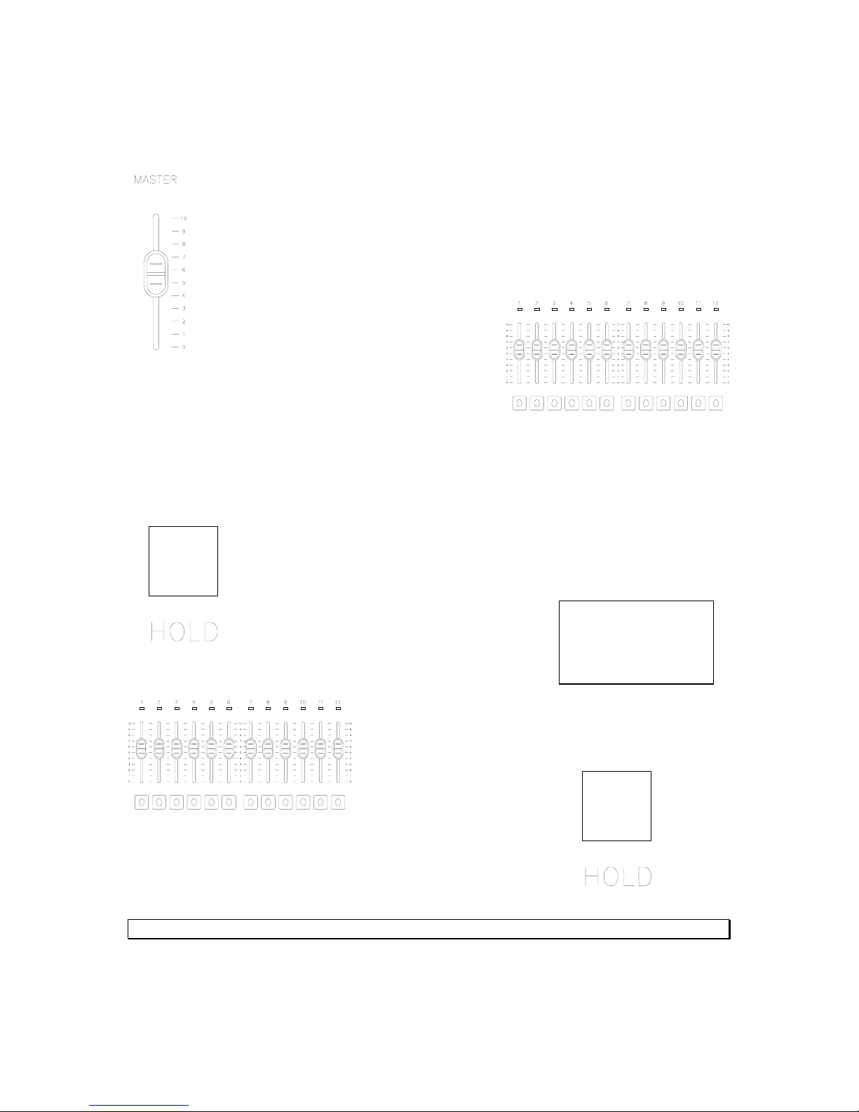
Make sure the Master is at full or the appropriate level.
Then set the faders 1 – 12 to the appropriate levels
to create the cue that is desired.
Hold – Two Scene Mode
The hold function allows the operator to “hold” or capture all levels on all active faders so
that all active faders can be reset to different levels to create a different cue.
To activate the hold feature press the Hold button.
The LCD screen now indicates that the hold
function has been activated by the flashing
<Hold> on the bottom line of text.
Now all active faders have been captured. Reset all
fader levels to the next cue.
Simply press the Hold button again and the new cue will
crossfade in while the old cue crossfades out.
See the LCD screen for countdown of crossfade using the default time.
Page 31
Strand 301 Console Manual Page 31
Multiple Units
Capacity
Each 301 console can capture one universe of DMX. There is maximum of 32 301 units that
can be connected.
Setup
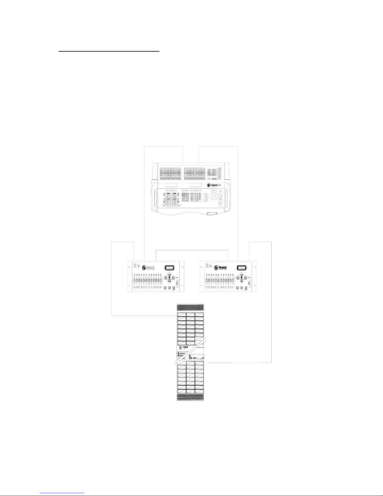
For a two unit system, Strand recommends that master controls the first universe of DMX
and that the slave controls the second universe of DMX. The diagram below shows the
recommended connection of equipment.
301 301
MASTER SLAVE
MAIN LIGHTING
CONSOLE
DMX UNIVERSE 1
DMX UNIVERSE 2
5 PIN DMX CABLE
5 PIN DMX CABLE
3 PIN LINK CABLE
DMX
IN
DMX
IN
LINK
IN
LINK
OUT
DMX 2
OUT
DMX 1
OUT
DMX
OUT
DMX
OUT
5 PIN DMX CABLE
DMX UNIVERSE 1
DMX UNIVERSE 2
5 PIN DMX CABLE
DIMMER RACKS 1
THRU 5
43
44
38
47
46
40
45
42
26
31
37
32
19
25
20
13
7
14
8
1
2
35
41
23
29
28
34
39
33
22
27
21
30
36
24
17
5
11
10
16
15
9
4
3
18
12
6
92
91
85
86
73
79
80
74
67
68
62
95
89
94
88
93
87
96
90
83
777175
76
82
81
70
64
69
84
78
72
66
50
55
61
56
49
59
65
53
52
58
63
57
51
54
60
SLD
6
9
48
3
PHASE
12 B
DMXAXOVERTEMP
MODULE EVENT
ACTIVE
PANIC
DIMMER RACKS 6
THRU 10
Page 32
Page 32 Strand 301 Console Manual
<Ms-f>
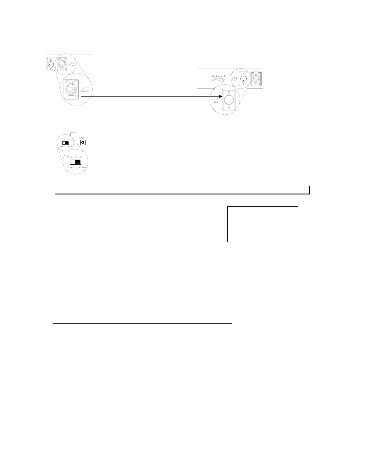
Connect a 3 pin cable to the link input of the master 301 console and connect
it to the link output of the slave 301 console.
Master to Slave
Set the Master / Slave switch appropriately on the back panel of each console.
Note: The LCD screen will always relay the current mode of the console.
If the console ever displays <Ms-f> (Master Fail) then
there are two 301 consoles set to master. Make sure
only the first 301’s master / slave switch is set to
master.
Operation
All operational procedures are the same in systems with multiple units adjusting for the fact
that each 301 console only controls one DMX universe each.
Analogue Input Operation
The analogue input on the back panel of the console is for remote fader control. Users can
connect a remote slider panel or 12 channel analogue console to the 301 for remote access
to the console’s 12 faders on page number 12 of backup mode. This input piles on in
backup mode with the highest level taking precedence.
Please note that the maximum current output from the analogue connector power pin is
200mA.
Page 33

Strand 301 Console Manual Page 33
Conclusion
This concludes the instructional manual for Strand’s 301 series console.
Accessories
A replacement vinyl cover is available for the console. Contact your local dealer for price
and availability.
Page 34
Page 34 Strand 301 Console Manual
Appendix A
Control Input
The DMX512 input will accept a multiplexed digital control signal which conforms to USITT
specification DMX512 (1990). Details of this specification are available from USITT on
request.
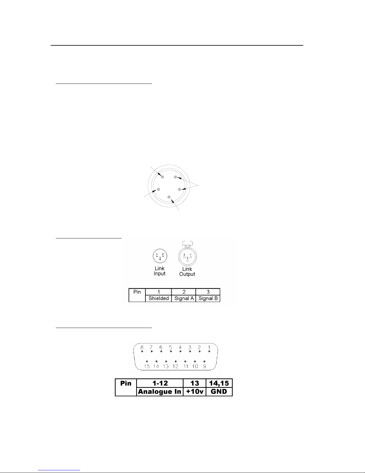
The control input is via a five-pin male XLR type connector. Pin connections are shown in
Figure 9. A five-pin female XLR connector is also fitted to allow a series of SD 6 packs (or
other DMX equipment) to be connected together in ‘daisy chain’ fashion.
Link Input
Analogue In
1
2
3
4
5
SHIELD
NOT CONNECTED
DMX -
DMX +
Page 35

Strand 301 Console Manual Page 35
Index
12 Channel Control Mode
12 Channel Control Mode.............................27
A
Accessories ...................................................33
Analogue In
Quick Guide..............................................10
Analogue Input Operation.............................32
Appendix A...................................................34
B
Back Plate .......................................................7
Back Up Cues on Multiple Pages
Back up mode ...........................................19
Back up Mode...............................................14
Basic Navigation
Operation...................................................13
C
Capacity
12 Channel Control Mode.........................27
Back up mode ...........................................14
Multiple Panels .........................................31
Timed Events Mode..................................21
Change Pages
Back up mode ...........................................18
Changing Modes
12 Channel Control Mode.........................27
Back up mode ...........................................14
Operation...................................................13
Timed Events Mode..................................21
Channel Faders
Quick Guide................................................9
Concept
Getting Started............................................6
Conclusion ....................................................33
Confirm
Navigation Keys in Quick Guide................9
Console Position Switch
Quick Guide..............................................10
Control Input.................................................34
Cross Fade Time
Back up mode ...........................................17
Cross Fade Time (XFtm)
12 Channel Control Mode ........................27
Current Page
Back up mode...........................................19
D
Default Patch
12 Channel Control Mode ........................29
Delete All Events
Timed Events Mode..................................22
Delete All Scenes
Back up mode...........................................16
Delete Event
Timed Events Mode..................................22
Delete One Event
Timed Events Mode..................................22
Delete One Scene
Back up mode...........................................15
Delete Page Scene
Back up mode...........................................15
Delete Scene
Back up mode...........................................15
Display Patch
12 Channel Control Mode ........................29
DMX IN
Quick Guide..............................................10
DMX Input
Quick Guide..............................................10
DMX Output
Quick Guide..............................................10
DMX512.......................................................34
Down
Navigation Keys in Quick Guide................9
E
Edit Patch
12 Channel Control Mode ........................28
Escape
Navigation Keys in Quick Guide................9
F
Face Plate........................................................7
Flash
Back up mode...........................................20
Flash Buttons
Page 36

Page 36 Strand 301 Console Manual
Quick Guide................................................9
G
Getting Started................................................6
H
Hold – Two Scene Mode
12 Channel Control Mode.........................30
Hold Button
Quick Guide................................................9
L
Layout.............................................................8
LCD Screen
Quick Guide..............................................10
LED Indicator Lights
Quick Guide..............................................10
Link Input .....................................................34
Quick Guide..............................................10
Link Output
Quick Guide..............................................10
M
Main Screen
12 Channel Control Mode.........................27
Back up mode ...........................................14
Timed Events Mode..................................21
Manual Playback of Timed Events
Timed Events Mode..................................24
Master
Quick Guide................................................9
Mechanical & Environmental Data
Getting Started............................................6
Menu
Back up mode ...........................................15
Timed Events Mode..................................21
Ms .................................................................11
Ms-f
Multiple Panel Setup.................................32
Multiple Panels .............................................31
N
Navigation Keys
Quick Guide................................................9
O
Offices and Service Centers............................3
One Scene Mode
12 Channel Control Mode ........................30
Operation......................................................13
Multiple Panels.........................................32
Ordering Information
Getting Started............................................6
P
Page
Quick Guide................................................9
Patch
12 Channel Control Mode ........................28
Playback of Back Up Scenes
Back up mode...........................................18
Power Connector
Quick Guide..............................................10
Q
Quick Guide....................................................9
R
Rack Mounting.............................................12
Record Scene
Quick Guide..............................................10
Recording of Back Up Scenes
Back up mode...........................................17
Recording of Timed Events
Timed Events Mode..................................23
S
Scheduling Playback of Timed Events
Timed Events Mode..................................24
Screen Menus for 12 Channel Control
12 Channel Control Mode ........................27
Screen Menus for Backup
Back up mode...........................................14
Screen Menus for Events Player
Timed Events Mode..................................21
Set Buzzer
Back up mode...........................................16
Timed Events Mode..................................23
Set Clock
Back up mode...........................................16
Page 37

Strand 301 Console Manual Page 37
Timed Events Mode..................................23
Set Default Fade Time
Timed Events Mode..................................22
Setup .............................................................11
Multiple Panels .........................................31
sl 11
Standards Compliance
Getting Started............................................6
Starting the Timed Events
Timed Events Mode..................................25
T
Table of Contents............................................4
Timed Events Mode......................................21
U
Unpack the Console
Getting Started............................................6
Unpatched Dimmers.....................................28
Up
Navigation Keys in Quick Guide................9
W
Welcome.........................................................2
 Loading...