

Page 1
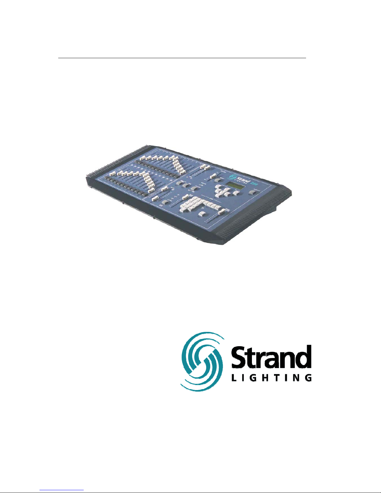
200 Console
Operations Manual
Manual
Part No. 24-004-0897
Page 2

Page 2 Strand 200 Console Manual
Welcome
Thank you for buying Strand Lighting control equipment. We hope
that you will find that your lighting needs are met by your new
system and that you will enjoy exploring the new facilities that your
new system offers. You are provided with essential information to
help you install and operate your system. Please look through all
the documents and keep them safely for future use. If you have
any difficulties, please do not hesitate to contact Strand Lighting or
any authorized Strand service center for advice.
This equipment is designed to operate from the main electrical
supply and contains voltages, which, if touched, may cause death
or injury. It should only be operated in accordance with the
instructions provided and for the purpose of a lighting control
system.
Do not open the console. There are no user serviceable parts
inside.
Avoid spilling liquid on the equipment If this should happen, switch
the equipment off immediately. To reduce the risk of fire or electric
shock, do not expose the equipment to rain or moisture.
For indoor use only.
This equipment is designed and manufactured to comply with
international safety standards 1EC950, UL1950, CS950 and is
intended for use as part of a lighting control system. It must not be
used for other purposes where there is a risk of safety to persons.
The equipment contains power voltages, socket outlets will be
installed near the equipment and be easily accessible.
• Working Voltage/Current 100-120 (2A) 220-240 (1A)
• Frequency 50/60 Hz
• Max Ambient Temp 35
0
C
• Do not restrict ventilation
This manual describes the installation and operational procedures
for Strand Lighting’s 200 Control Console
.
Page 3

Strand 200 Console Manual Page 3
Offices and Service Centers
Please confirm all country codes or other international access data.
World Wide Web: http://www.strandlighting.com/
Berlin
Strand Lighting GMBH
Ullsteinstrasse. 114-142, HAUS C
D-12109
Berlin, Germany
Tel. +49-30-707-9510 Fax +49-30-707-95199
Hong Kong
Strand Lighting Asia LTD
20/F., Delta House
3 On Yiu Street
Shatin, N.T.
Hong Kong
Tel. +852-2757-3033 Fax +852-2757-1767
London
Strand Lighting Limited
Unit 3 Hammersmith Studios
Yeldham Road
Hammersmith
London, England W6 8JF
Tel. +44-20-8735-9790 Fax +44-20-8735-9799
Los Angeles
Strand Lighting Inc
6603 Darin Way
Cypress, CA 90630
U.S.A.
Tel. +1 714-230-8200 Fax +1 714-230-8173
Moscow
Strand Lighting
Novinsky Boulevard 20A Building 3-6
12069 Moscow, Russia
Tel. +7 095-234-42-20 Fax. +7 095-234 42-21
Rome
Strand Lighting Italia
Via Delle Gardenie S.N.C.
Pontina Vecchia KM 33,400
00040 Pomezia, Italy
Tel. +39-0691-9631 Fax +39-0691-47138
Toronto
Strand Lighting (Canada) Inc
2430 Lucknow Drive #15,
Mississauga, Ontario, L5S 1V3
Canada
Tel. +1 905-677-7130 Fax. +1 905-677-6859
Page 4

Page 4 Strand 200 Console Manual
Table of Contents
Welcome ................................................................................................................................. 2
Offices and Service Centers ................................................................................................... 3
Table of Contents.................................................................................................................... 4
Getting Started........................................................................................................................ 6
Concept............................................................................................................................... 6
Ordering Information ........................................................................................................... 6
Mechanical & Environmental Data...................................................................................... 6
Standards Compliance........................................................................................................ 6
Unpack the Console............................................................................................................ 6
Layout ..................................................................................................................................... 7
Layout ..................................................................................................................................... 8
Quick Guide ............................................................................................................................ 9
Terminology Notes............................................................................................................ 11
Setup..................................................................................................................................... 12
Operation .............................................................................................................................. 13
Single Scene Mode........................................................................................................... 13
Basic Operation............................................................................................................. 13
Hold................................................................................................................................... 14
Time Fades for Hold...................................................................................................... 14
Two Scene Mode .............................................................................................................. 15
Basic Operation............................................................................................................. 15
Crossfade...................................................................................................................... 15
Dipless Manual Crossfade ........................................................................................ 16
Time Fades ................................................................................................................... 16
Submaster Mode............................................................................................................... 17
Basic Operation............................................................................................................. 17
Recording Submasters.................................................................................................. 18
Submaster Pages.......................................................................................................... 19
Changing Submaster Pages ..................................................................................... 19
Recording Submasters on Page 2 ................................................................................ 19
Crossfade between Submasters ................................................................................... 20
Additional Information for Submaster Crossfading........................................................ 20
Advanced Features...............................................................................................................21
Effects ............................................................................................................................... 21
Programming an Effect ................................................................................................. 21
Effect Mode ............................................................................................................... 22
Effect Direction.......................................................................................................... 22
Additional Information for Effects .............................................................................. 22
Effects Playback............................................................................................................ 23
Additional Information for Effects Playback............................................................... 23
Running Effects on Submasters................................................................................ 24
Editing an Effect ............................................................................................................ 25
Effect Delete Options .................................................................................................... 26
Delete an Effect Step ................................................................................................ 26
Delete an Effect......................................................................................................... 26
Delete an Effect Page ............................................................................................... 27
Inserting an Effect Step................................................................................................. 27
Effect Fade Time Options ............................................................................................. 28
Page 5

Editing Effect Fade Time........................................................................................... 28
Reset Effect Fade Time to Zero ................................................................................ 28
Scene Options .................................................................................................................. 29
Edit a Scene.................................................................................................................. 29
Delete Scene Options ................................................................................................... 30
Delete One Scene..................................................................................................... 30
Delete Page Scene ................................................................................................... 30
Crossfade Start Scene Option ...................................................................................... 31
Setup..................................................................................................................................... 32
Patch................................................................................................................................. 32
Edit Patch......................................................................................................................32
Unpatch a Dimmer .................................................................................................... 33
Proportional Patch..................................................................................................... 33
Display Patch ................................................................................................................ 33
Default Patch................................................................................................................. 34
Unpatch Patch............................................................................................................... 34
Additional Information for Patch .................................................................................... 34
Multiple Channel Patch Matrix .................................................................................. 34
Self Test............................................................................................................................ 35
MIDI .................................................................................................................................. 36
Audio................................................................................................................................. 38
LCD Settings..................................................................................................................... 39
Show File .......................................................................................................................... 40
Save Show .................................................................................................................... 41
Set Buzzer ........................................................................................................................ 43
Conclusion ............................................................................................................................ 44
Accessories........................................................................................................................... 44
Appendix A............................................................................................................................ 45
Control Input ..................................................................................................................... 45
Audio Input........................................................................................................................ 45
Index ..................................................................................................................................... 46
Strand 200 Console Manual Page 5
Page 6

Page 6 Strand 200 Console Manual
Getting Started
Concept
The Strand 200 series console is a mid-level preset lighting desk that is available
in two sizes. A 12/24 channel version and a 24/48 channel version. The 12/24
channel version can either control 24 channels in 1 scene or 12 channels in 2
scenes with the ability to expand scenes with the Hold feature. The 24/48
channel version can either control 48 channels in 1 scene or 24 channels in 2
scenes with the ability to expand scenes with the Hold feature.
Both versions of the console patch a single universe of DMX-512 and can contain
up to 24 effects (99 steps) - (6 effects x 4 pages), A submaster can be recorder
for every fader and advanced features such as Audio/MIDI are available.
Ordering Information
Catalog # 64312 – 200 series 12/24 console 120 volt
Catalog # 64313 – 200 series 12/24 console 230/240 volt
Catalog # 64320 – 200 series 24/48 console 120 volt
Catalog # 64321 – 200 series 24/48 console 230/240 volt
Catalog # 64315 – Dust Cover 200 12/24
Catalog # 64325 – Dust Cover 200 24/48
Mechanical & Environmental Data
Weight: 12/24 – 6.9 kg unpacked 9.5 kg packed
24/48 – 9.5 kg unpacked 12.5 kg packed
Finish: Blue powder coat epoxy paint
Construction: Rigid folded sheet steel
Temperature: 0 – 35°C
Humidity Range: 0-90% non-condensing
Ingress Protection: IP20
Standards Compliance
All units are CE marked. 120 volt consoles include UL, cUL power supplies.
Unpack the Console
Unpack the console from the packaging and check that the following components
are contained within. If any parts are missing, or damaged, please contact the
carrier and the nearest Strand Lighting office.
List of Parts for North America…
(1) 200 series console
(1) Power cable with UL power supply cable with US 2 pin connector
(1) Manual
List of Parts for Europe and Asia…
(1) 200 series console
(1) Power cable with cUL power supply cable with
(1) UK 2 pin connector and EU 3 pin connector
(1) Manual
Page 7
Strand 200 Console Manual Page 7
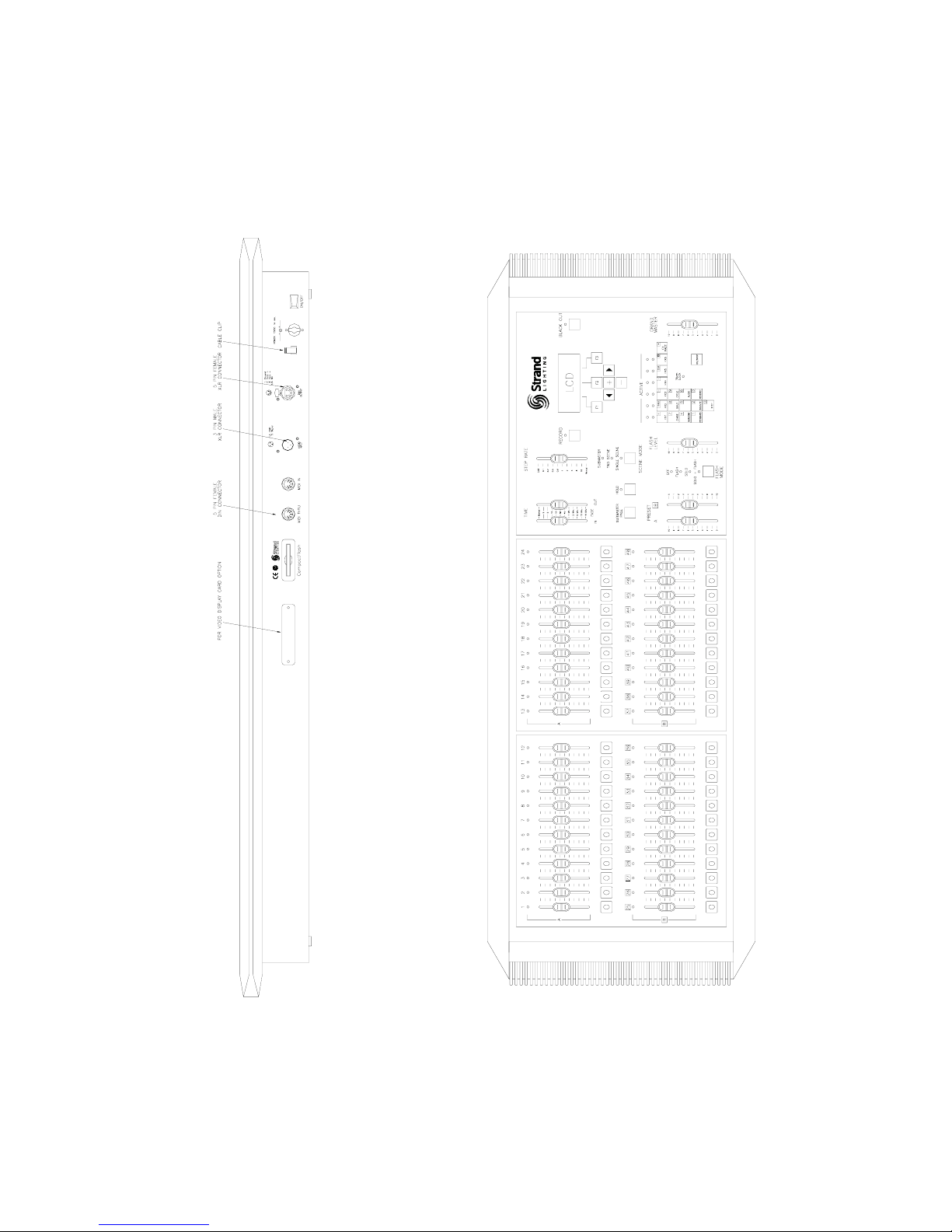
Back Plate of 24/48
Note: The 12/24 model (not shown) contains only one fader panel.
Face Plate of 24/48
Page 8
Page 8 Strand 200 Console Manual
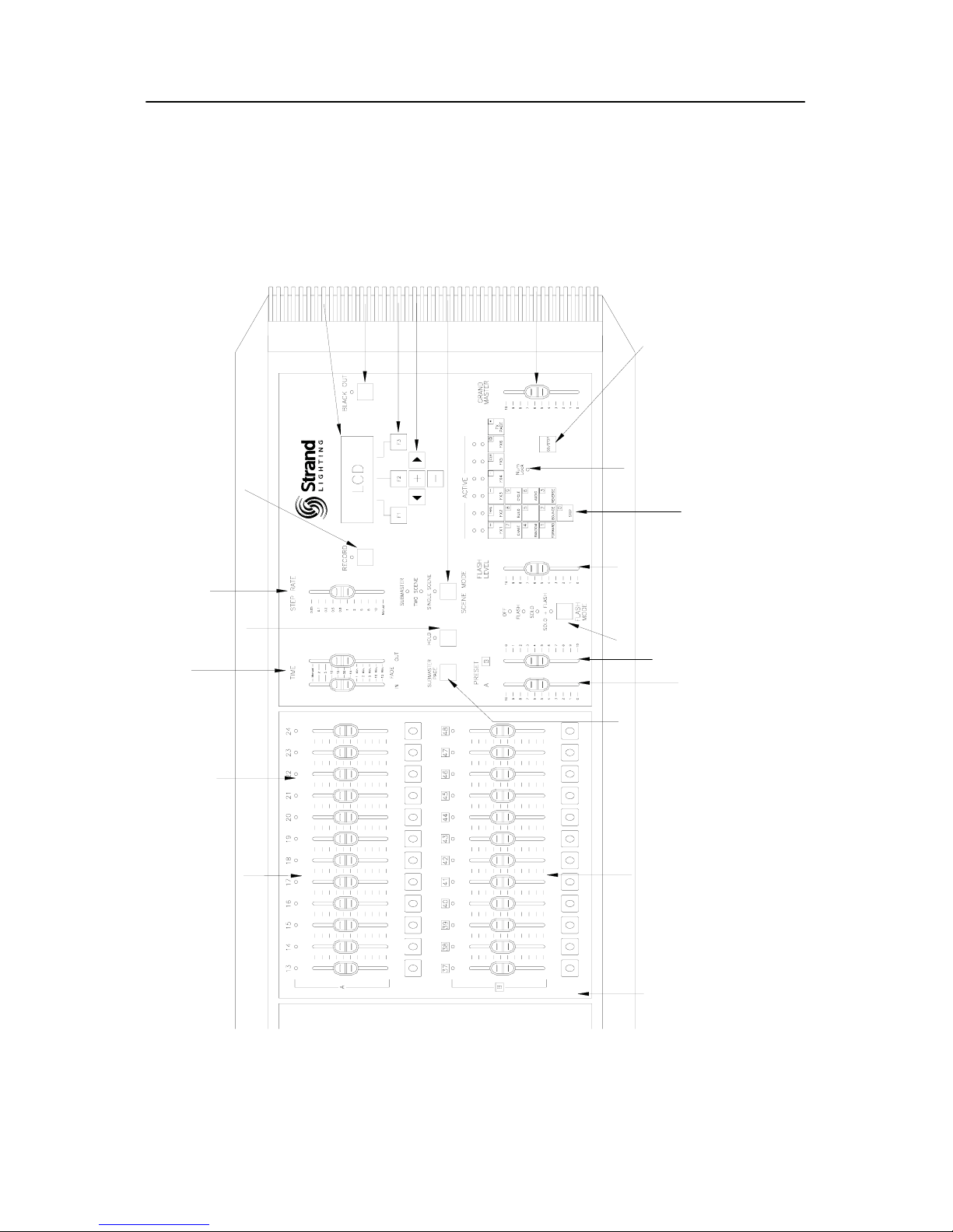
Layout
11. CHANNEL LED INDICATORS
14. SCENE B FADERS
12. SCENE A FADERS
13. FADER FLASH BUTTONS
9. HOLD
BUTTON
7. RECORD BUTTON
10. SPLIT TIME FADERS
8. STEP RATE FADER
21. NUMBER LOCK
INDICATOR
20. EFFECTS TILE
16. PRESET A
MASTER
15. SUBMASTER
PAGE BUTTON
19. FLASH
LEVEL
18. FLASH
MODE
17. PRESET B
MASTER
6. LCD SCREEN
5. BLACKOUT BUTTON
4. FUNCTION KEYS
3. NAVIGATION KEYS
2. MODE BUTTON
22. GO / STOP BUTTON
1. GRANDMASTER
Note: Only one fader panel is fully shown.
Page 9

Strand 200 Console Manual Page 9
Quick Guide
1. Grand Master– an inhibitive fader that proportionately controls all other level faders. This
determines maximum output of all faders at all times. The master is always active.
2. Mode Button - toggles the console between the 3 different modes; submaster mode, two
scene mode and single scene mode. The LED will show current mode.
3. Navigation Keys– these keys allow for navigating within the LCD screen.
4. Function Keys – these keys allow access to all scene, effect and setup change functions.
F1 – the function of this key will be displayed at the bottom left of the LCD screen. It
allows the operator to go back a screen.
F2 – the function of this key will be displayed at the bottom center of the LCD screen.
It allows the operator to advance screens within a function.
F3 – the function of this key will be displayed at the bottom right of the LCD screen. It
allows the operator to confirm an operation.
5. Blackout Button– when pressed, all levels go to zero. (The flashing LED above the
button will indicate this) Press again, and all levels will return.
6. LCD Screen – displays current information about the console’s status.
7. Record Button – allows recording of levels of faders. When pressed, the LED above will
flash indicating the console is in record mode.
8. Step Rate Fader – changes rate of effect steps according to level. The range is from
0.05 seconds to 10 seconds with manual being at zero.
9. Hold Button – this button will freeze the output of the faders so that the operator can
reset the channel faders for a different look or cue. This feature only works in one scene
mode.
10. Split Time Faders – allows the operator to set a timed fade for the levels going up (IN)
and a different timed fade for the levels going down (OUT). The range is from manual to 15
minutes.
11. Channel LED Indicators – each fader has one and it will glow in proportion with the
fader level.
12. Scene A Faders –
Submaster mode – all faders are submasters and not controlled by Preset A.
Two scene mode - top row of faders are mastered by Preset A.
One Scene mode – all faders are mastered by Preset A.
Page 10

Page 10 Strand 200 Console Manual
22. Go / Stop Button – allows start and stop of effects.
13. Fader Flash Buttons - will flash the corresponding fader according to the flash mode
and the flash level.
14. Scene B Faders –
Submaster mode – all faders are submasters and not controlled by Preset B.
Two scene mode - bottom row of faders are mastered by Preset B.
One Scene mode – all faders are mastered by Preset A.
15. Submaster Page Button – toggles between page 1 and page 2 of the submaster pages.
The active page will be indicated on the LCD screen as Scene Pg:#
16. Preset A Master –
Submaster mode – used for crossfades between scenes.
Two scene mode – masters the top row of faders.
One Scene mode – masters all faders.
17. Preset B Master –
Submaster mode – used for crossfades between scenes.
Two scene mode – masters the bottom row of faders.
One Scene mode – disabled.
18. Flash Mode –
Off – disabled.
Flash – flashes the level of the corresponding fader. This is mastered by the flash
level master.
Solo – flashes the level of the corresponding fader and takes all other faders to zero.
Solo+Flash – flashes the level of the corresponding fader and takes all other faders
to zero. This is mastered by the flash level master.
19. Flash Level – this sets the level of the flash function.
20. Effects Tile – this grouping of keys allows for recording of effects.
21. Number Lock Indicator – this LED indicates that the Number Lock is on. It allows the
effects tile to become a numeric keypad.
Page 11

Strand 200 Console Manual Page 11
DMX Output – accepts a DMX512 5 pin XLR connector from the dimmers or any other DMX
device.
Audio Input – allows a fader to control the audio trigger threshold from an audio source
connected to the console.
MIDI Input – allows an external source to control the triggering of effects from the console.
(MIDI stands for Musical Instrument Digital Interface)
MIDI Thru – allows the in-line connection of the console from one MIDI source to another.
Power Connector – accepts the power adaptor from the power transformer.
Console Power Switch – rocker switch to turn power to the console on and off.
Compact Flash Slot – allows for saving of shows onto a compact flash card. Only a 32M
compact flash card can be used. The compact flash card has to be dedicated to the 200
console. It cannot share with other devices due to a different file format. The show file
cannot be read on a standard PC.
Video Display Card (optional) – allows for the addition of a video display card for a display
monitor.
Terminology Notes
It is easy to confuse the terms of scenes and submasters. The following information will help
clarify…
Submasters – faders that contain cues or looks that are played back manually.
Scenes – faders that contain cues or looks that are played back via the playback faders.
All
levels recorded into scenes will be controlled by the submaster of the same number.
Page 12
Page 12 Strand 200 Console Manual
Setup
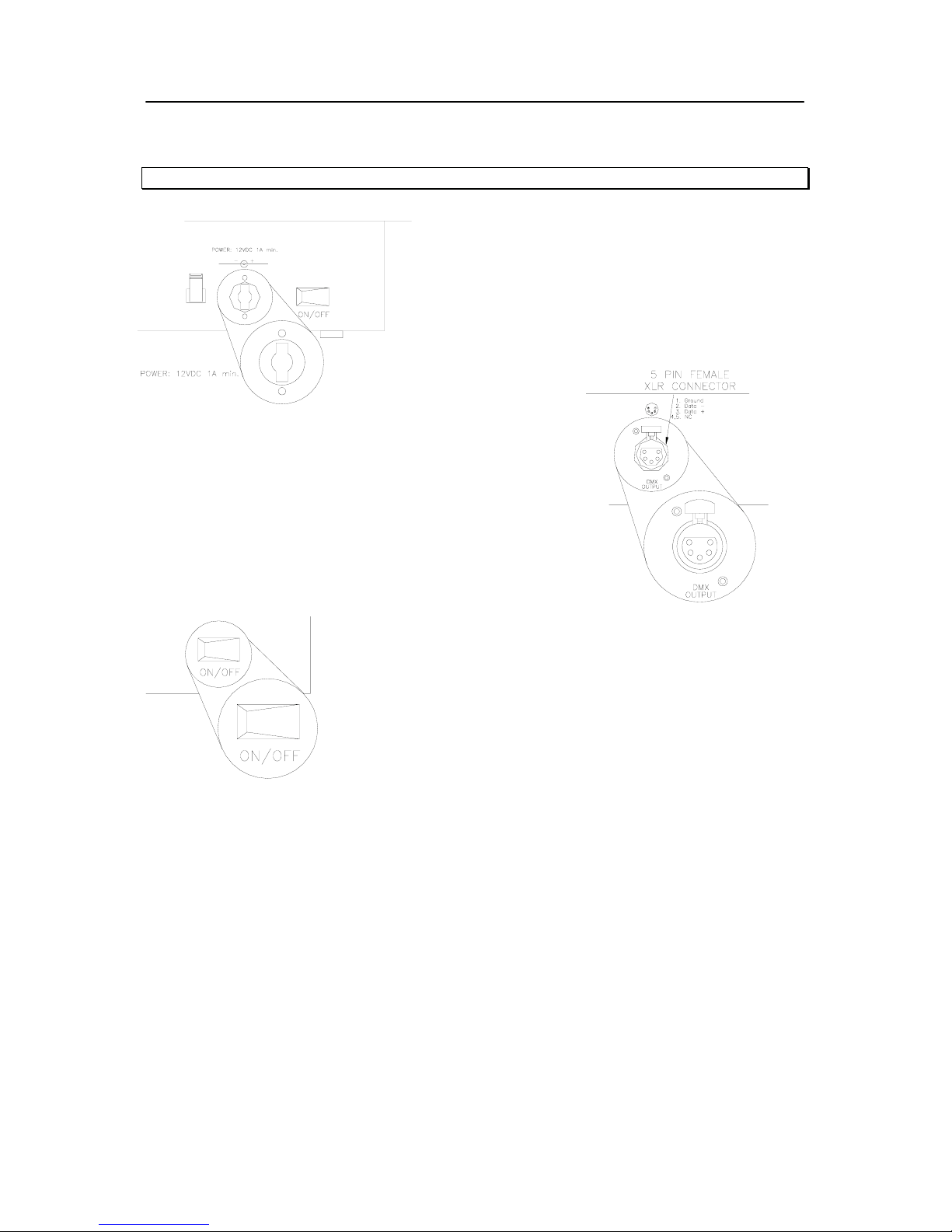
Note: The power supplies are pack in the side of the packing material.
Plug the appropriate power adaptor into the console
where shown. Plug the male end into the
appropriate electrical service.
Plug the DMX
DMX device) into the DMX
Turn the console on via the rocker switch on the back plate and
the console is ready to go!
The 200 console will go through a self-test and return to the last known state.
512 cable from the dimmer rack (or any
512 output of the 200 console.
Page 13
Strand 200 Console Manual Page 13
Operation
Single Scene Mode
Basic Operation
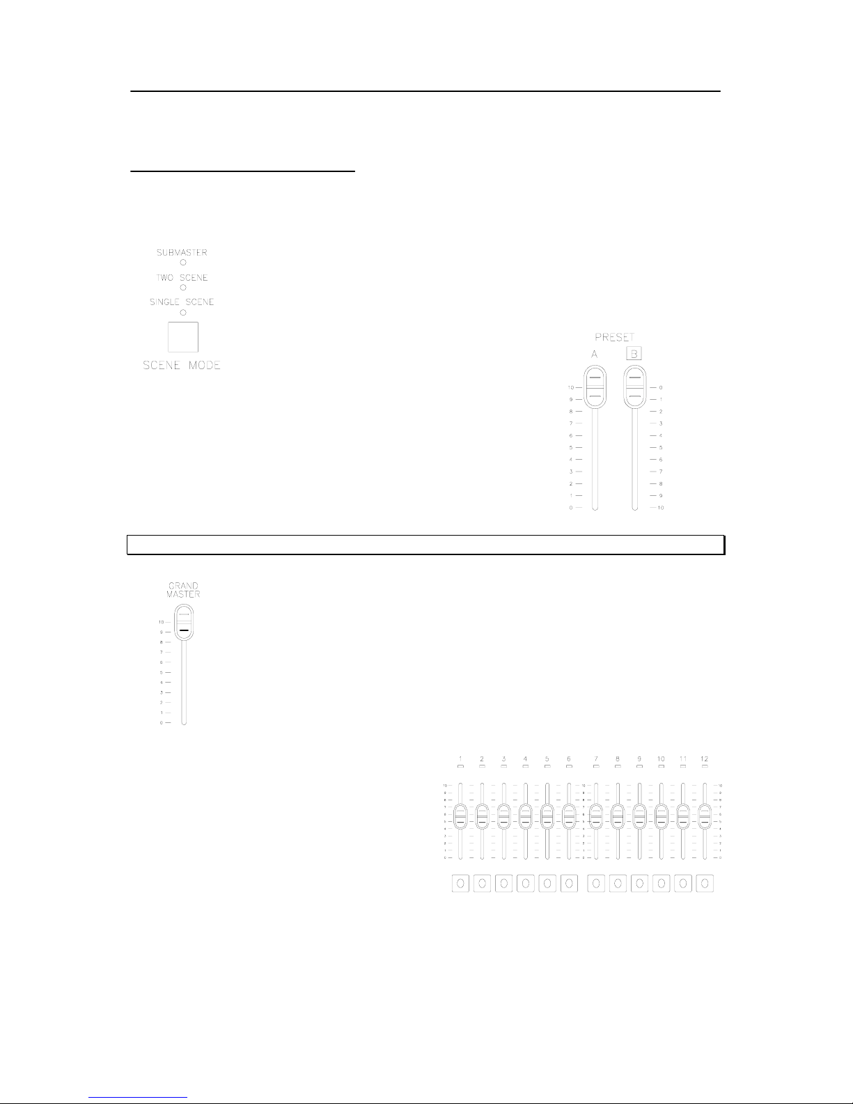
First, make sure the console is in single scene mode by identifying the
scene mode LED indicator. The LED below single scene will be lit. If not,
toggle the scene mode button until the proper LED is glowing.
Adjust the preset A master to full (UP) and the preset B
master to 0 (UP)
Note: Preset master levels will be shown on the LCD screen.
Make sure the grand master is at full.
Provide level to any combination of faders.
This will bring up each dimmer on a one to
one basis with the fader for the number of
faders on your console. (i.e. fader 1 brings
up dimmer 1, fader 15 brings up dimmer 15)
If this is the 12/24 model, the operator has
control of 24 faders. If this is the 24/48
model, the operator has control of 48 faders.
See the Patch section to change the dimmer assignment.
Page 14
Page 14 Strand 200 Console Manual
Hold
In single scene mode only, using hold allows the operator to freeze all
dimmer output and manually reset the levels for all faders to create a
different look on stage. Here’s how it works…
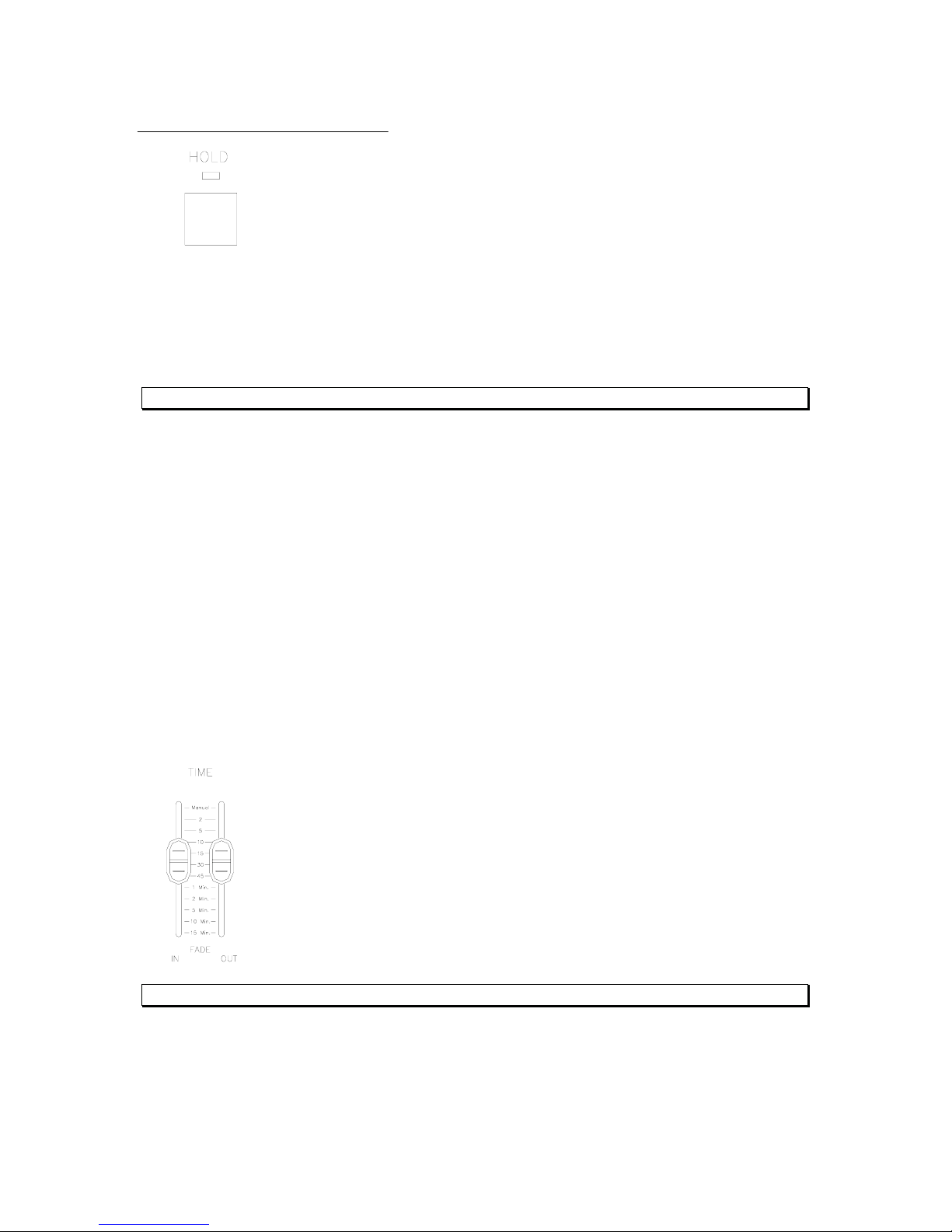
Select current settings with channel faders. Make sure playback A
master is at 10 and playback B master is at 0. (That’s both playbacks
in the UP position). The hold feature can only be activated and deactivated with playbacks in
these positions. Press the hold key (The hold LED will now be on), move playback A’s
master to 0 while moving playback B’s master to 10 (both down). During the crossfade, the
hold LED will be flashing. Although no levels are changing, all levels are now held from the
moment the masters begin to move.
The LCD will also support this by the Preset B:HOLD flashing.
The current fader settings will now be recorded into hold’s memory. (The hold LED will stop
flashing but remain on indicating the activation of the hold feature. The operator is now free
to reset all channel faders to the levels for the next cue. Once the channel faders are set,
crossfade playback A’s master back to 10 and playback B’s master back to 0. (During
crossfade the hold LED will flash) After a crossfade is completed, the second cue will now
be outputting live. (The hold LED will still be on) Repeat the above step for the next
crossfade or press hold again to release the hold function. After pressing hold, the hold LED
will turn off.
Also note, that playback B is now the master for the held scene. So if playback B is moved
to 0 (UP) then the held state fades out.
The hold feature only works in single scene mode.
Smooth timed crossfades between the held and active scene can be
achieved by setting the time fade faders. The left fader is for all levels that
are going up (IN) and the right fader is for all levels going down (OUT). (i.e.
If the operator is crossfading out of a held scene and into the current fader
levels, then the in fader will affect the time of the current fader levels
coming in while the out fader will affect the time of the held scene going out).
Note: All crossfades done in this manner are dipless.
Time Fades for Hold
Page 15
Strand 200 Console Manual Page 15
Two Scene Mode
Basic Operation
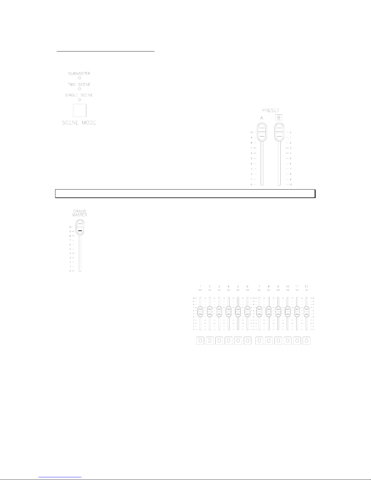
Make sure the console is in two scene mode by identifying the scene
mode LED indicator. The LED below two scene will be lit. If not, toggle
the scene mode button until the proper LED is glowing.
Adjust the preset A master to full (UP) and the preset B master
to 0 (UP)
Operating both preset faders UP and DOWN at the same time
allows for dipless crossfades.
ster levels will be shown on the LCD screen. Note: Preset ma
Make sure the grand master is at full.
Provide level to any combination of faders.
This will bring up each dimmer on a one to
one basis with the fader for the number of
faders on your console. (i.e. fader 1 brings
up dimmer 1, fader 15 brings up dimmer 15)
If this is the 12/24model, the operator has
control of 12 faders in 2 scenes. If this is the
24/48 model, the operator has control of 24
faders in 2 scenes.
See the Patch section to change the dimmer assignment.
Crossfade
A crossfade allows one scene to fade out as another scene is faded in.
Page 16
Page 16 Strand 200 Console Manual
Dipless Manual Crossfade
The reverse configuration of the preset B master allows the operator to have both faders set
in the up position (A will be at 100%, B will be at 0%) and move them at the same time in the
same direction physically while the light levels from both presets move in the opposite
direction.
Note: Remember, there must be levels in faders that are controlled by BOTH preset masters for the
dipless manual crossfade to function properly.
Time Fades
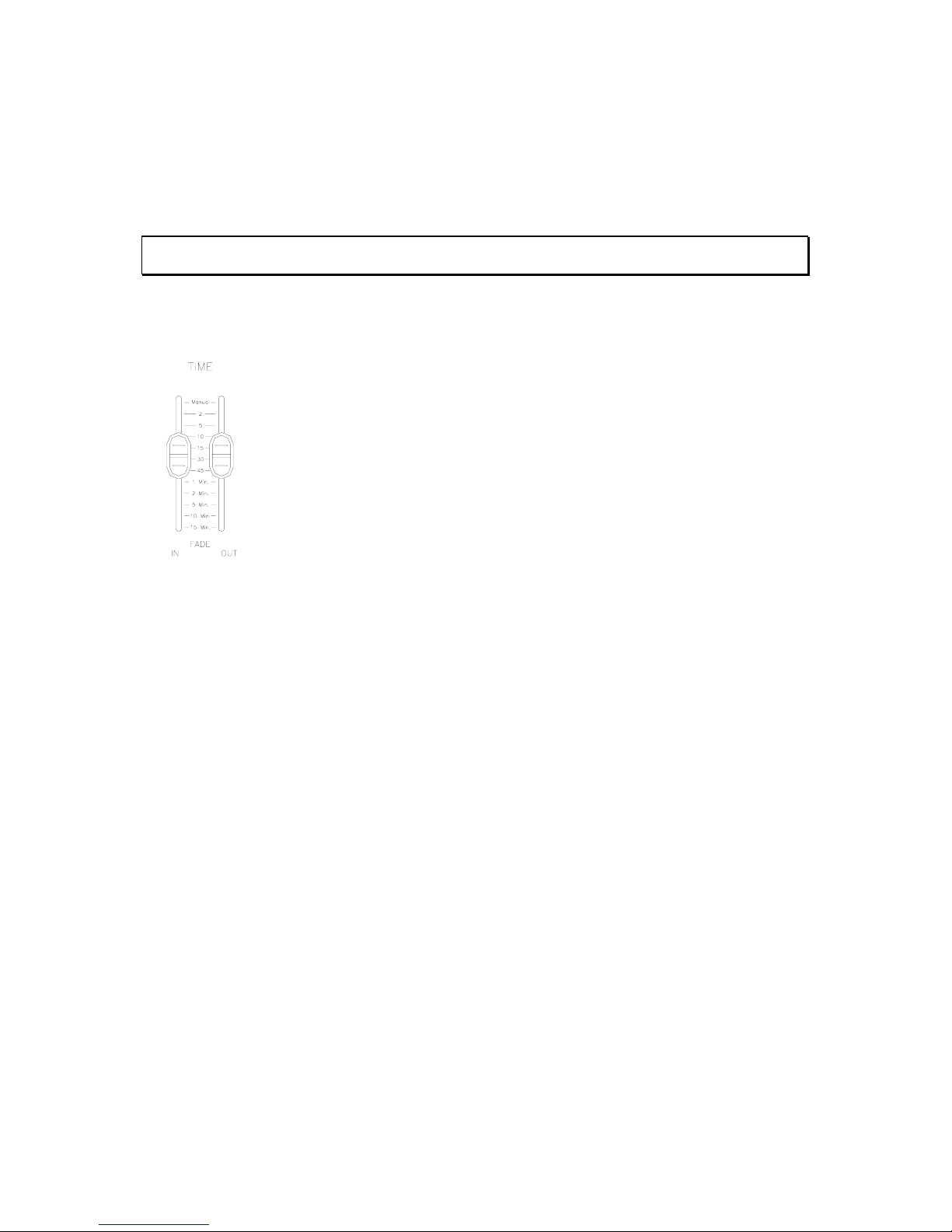
Smooth timed crossfades can be achieved by setting the time fade faders.
The left fader is for all levels that are going up (or fading in) and the right
fader is for all levels going down (or fading out). (i.e. If the operator is
crossfading out of preset A and into preset B, then the in fader will affect the
time of preset B coming in while the out fader will affect the time of preset A
going out).
Page 17
Strand 200 Console Manual Page 17
Submaster Mode
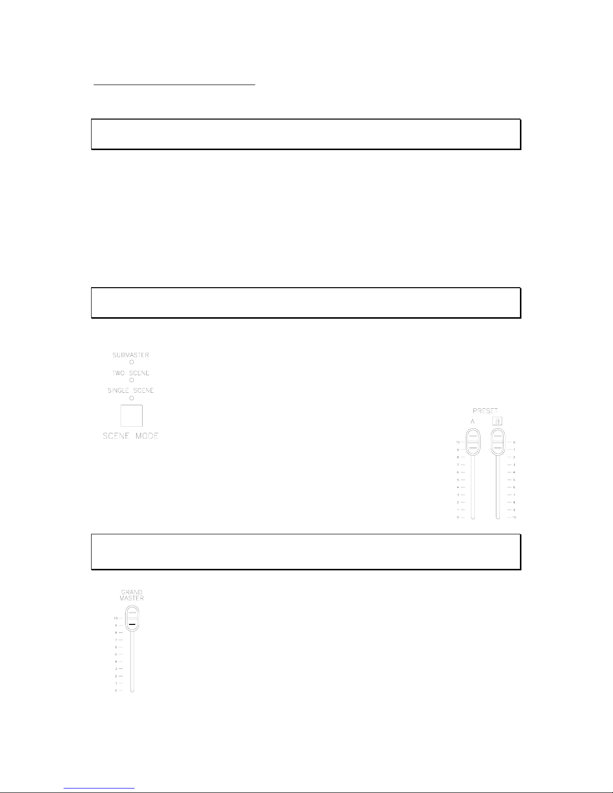
Basic Operation
Note: Submasters are faders that contain cues or looks that are played back manually.
Scenes are faders that contain cues or looks that are played back via the playback faders.
Submaster mode allows the operator to record a different look or scene into every fader
times 2 as the console has 2 submaster pages. The current page is identified on the LCD
screen by Scene Pg:#.
To record a submaster, the console must be in either single or two scene mode to bring up
faders. Recorded from either of these modes, then activated after switching to the
submaster mode to play the submasters.
Also, multiple scenes can be recorded into a single submaster.
Note: A combination of scenes and effects cannot be recorded into a single submaster.
The effects will be ignored.
Make sure the console is in single scene mode by identifying the scene
mode LED indicator. The LED below single scene will be lit. If not, toggle
the scene mode button until the proper LED is glowing.
Adjust the preset A master to full (UP) and the preset B master to 0 (UP)
Note: Submasters work in a highest takes precedent mode. So, if either preset master has a level
and faders have levels (indicated by green LEDs) then the console will pile on the submasters levels
to the current fader levels.
Make sure the grand master is at full.
Page 18
Page 18 Strand 200 Console Manual
Recording Submasters
Provide level to any combination of faders (or scenes in submaster mode). Assuming the
patch has not been edited yet, this will bring up each dimmer on a one to one basis with the
fader for the number of faders on your console. (i.e. fader 1 brings up dimmer 1, fader 15
brings up dimmer 15) If this is the 12/24 model, the operator has control of 24 faders. If this
is the 24/48 model, the operator has control of 48 faders.
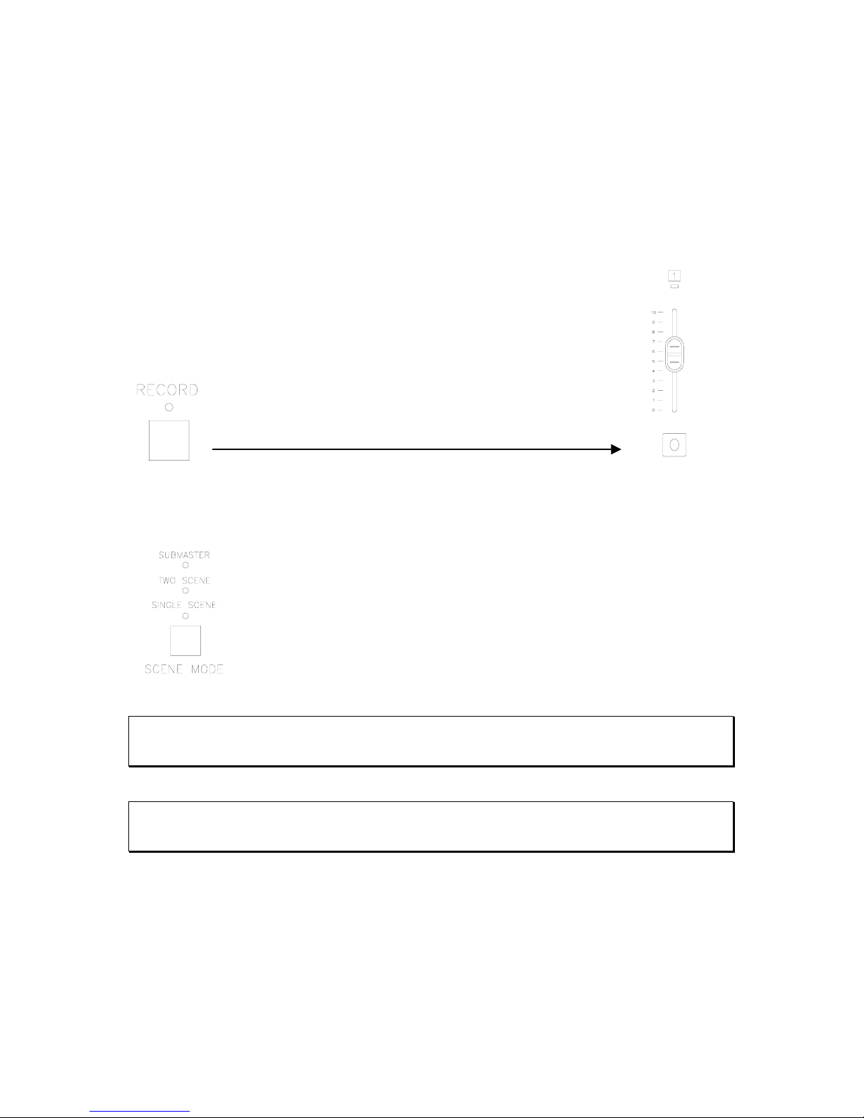
Press the record button. The LED indicator will start flashing.
(Notice that any flashing amber LED indicates that the fader has already
been loaded with a scene. A new scene can overwrite any previously
recorded scene or effect.)
Press and hold the flash button to the appropriate fader until
it’s LED starts flashing.
Press the record button again and all LEDs will go out. This is the console’s indication that
the recording process is complete.
Switch to submaster mode and take all channel faders to zero. The
submaster that was just recorded will be indicated by the amber LED that
corresponds to the fader that was just recorded.
Take that fader to full and the lights will go to the recorded level.
Note: After switching to submaster mode with a live fader, the faders hold their levels even though
the mode has been switched. Any fader having any level will hold through a mode change until the
fader is taken to zero.
Note: When switching from submaster mode to any scene mode with a live submaster. It will hold its
levels until the submaster is taken to zero. This will be indicated by the amber LED of the appropriate
submaster flashing.
Page 19
Strand 200 Console Manual Page 19
Scene Pg: 1 Fx Pg: 2
Preset A: FL B: 00
Scene FX Setup
Submaster Pages
There are two submaster pages on the 200 console.
They are also referred to as scenes on the LCD
screen. The submaster page can be identified by
the scene page number on the LCD screen.
Changing Submaster Pages
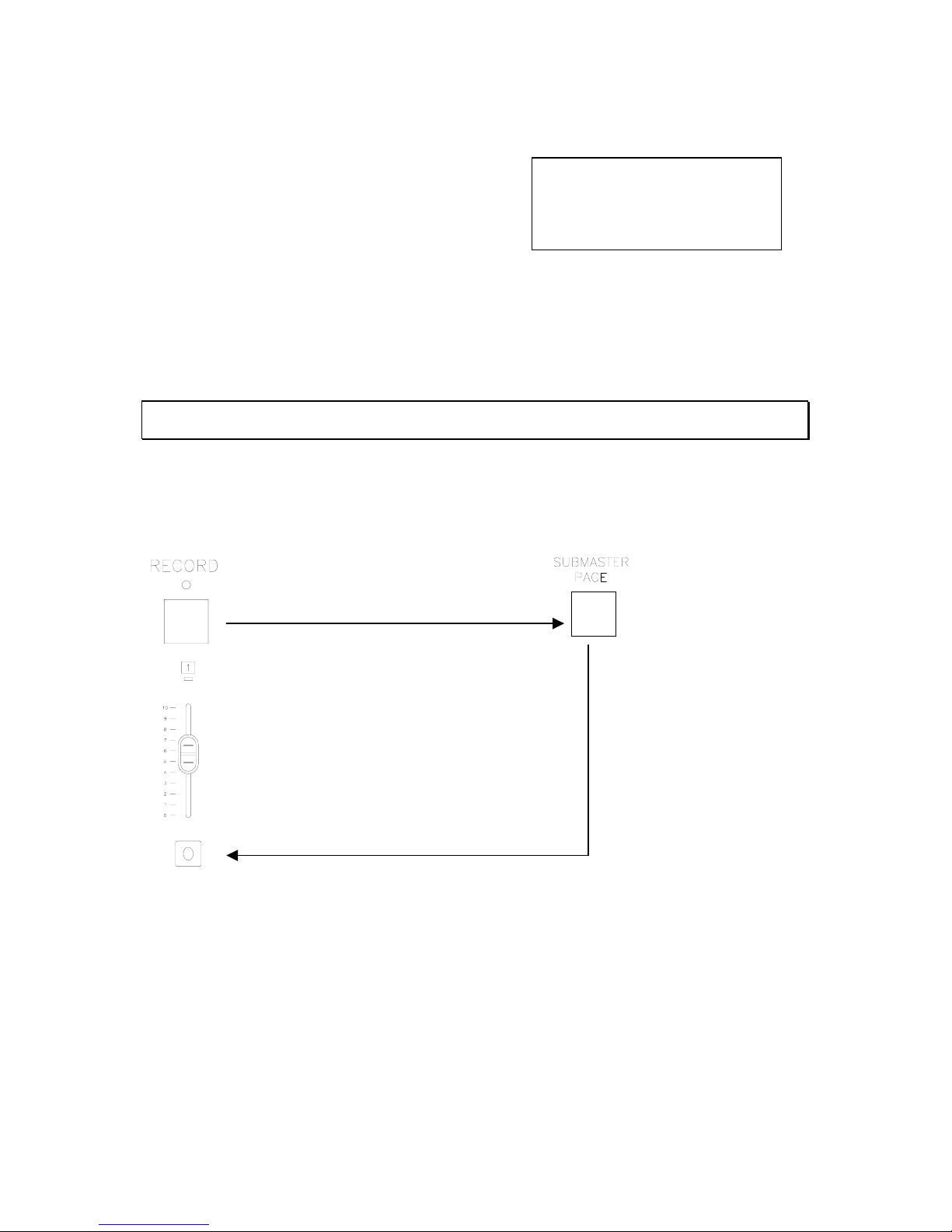
Changing submaster pages is as simple as pressing the submaster page button. The LCD
will always identify the current submaster page.
Note: When switching between submaster pages, any active submaster will be indicated by its
flashing LED indicator.
Recording Submasters on Page 2
Press the record button. The LED indicator will start flashing.
Press and hold the flash button to the
appropriate fader until it’s LED starts flashing.
Press the submaster page button.
Page 20
Page 20 Strand 200 Console Manual
Crossfade between Submasters
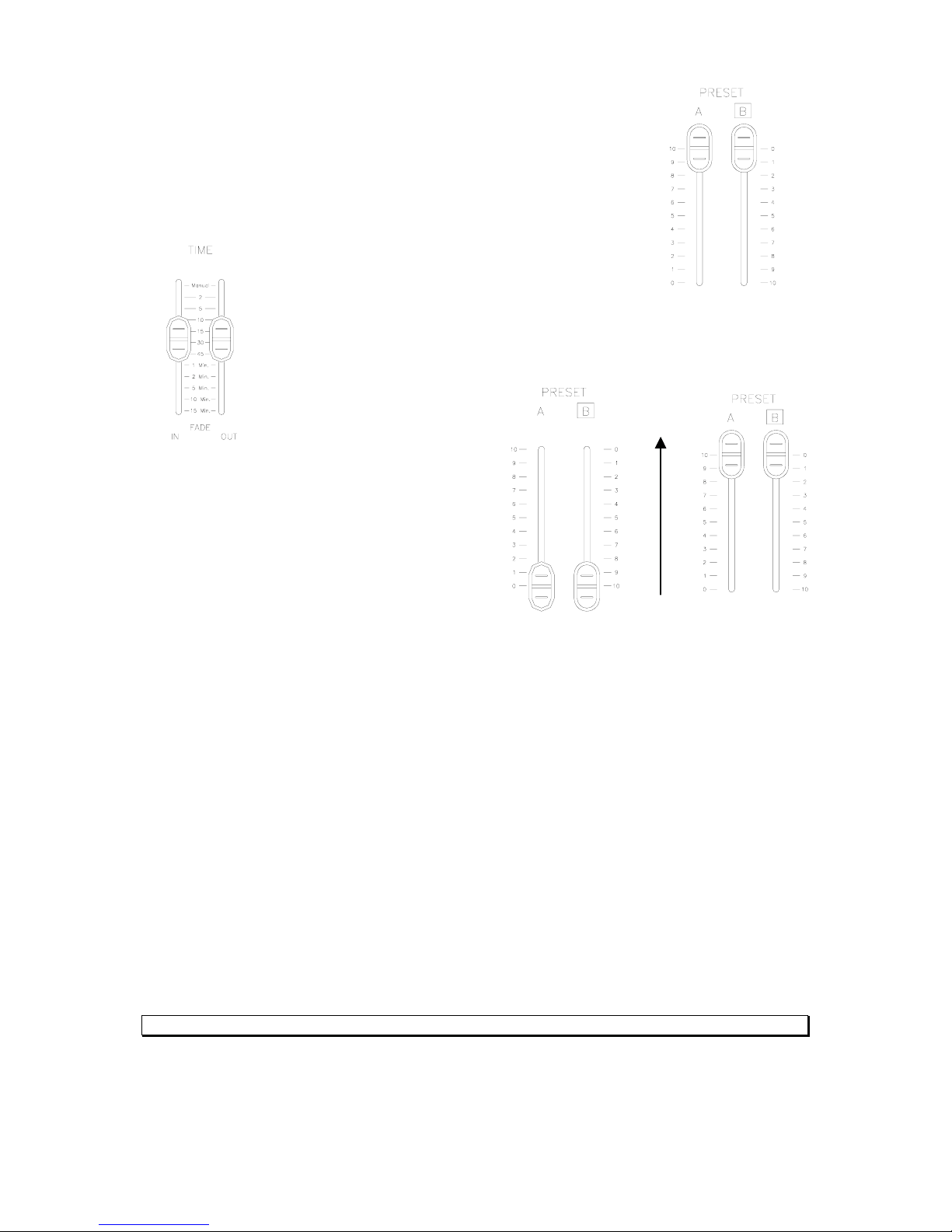
Aside from the normal two fader crossfade, in submaster mode the
operator can crossfade in sequence. Make sure the preset A & B
masters are in the UP position.
Set the In – Time Fade fader to the desired fade in time and set the Out –
Time Fade to the desired fade out time.
Move the preset A & B masters down (the first
recorded fader’s LED will begin
Now move the preset A & B masters up to
fade in the first scene (the first recorded
faders LED will stop flashing and the scene
will fade in.
When the fade is complete the second recorded fader’s LED
will begin flashing green). Repeat down and up master action to continue crossfading
between scenes. This will crossfade the second scene with the first one. Repeating the
process will crossfade all available scenes until it reaches the last scene of page two and
then returns to the first recorded scene of page one again.
Additional Information for Submaster Crossfading
• To stop the crossfade, move only preset A master down and then up. This will fade
out the last output scene.
• Changing mode will also stop the crossfade immediately and take out the last fade
output and is not recommended.
• Any empty submasters, submasters with effects or submasters that already have a
level, will be ignored. For example, If any of the submasters are already in the up
position (i.e. outputting a level), the sequential crossfade will start from the scene
immediately after the highest outputting fader (i.e. If fader 1,3,5 are up, the crossfade
will start from scene 6).
• The LCD screen will show the fader percentage values for both the fade in and fade
out as the fade is occurring.
Note: See Crossfade Start Scene Option for changing the submaster that is crossfaded first.
flashing green)
Page 21
Strand 200 Console Manual Page 21
Advanced Features
The advanced features section will cover advanced programming items such as effects,
scene editing and setup.
Effects
The effects feature of the 200 console, allows the operator to program and run a sequence
of levels or cues at a rate that ranges from 0.05 seconds to 10 seconds per step or stepped
through manually or triggered by an audio / MIDI signal.
There are 4 pages of 6 effects per page with a maximum of 99 steps per effect.
Programming an Effect
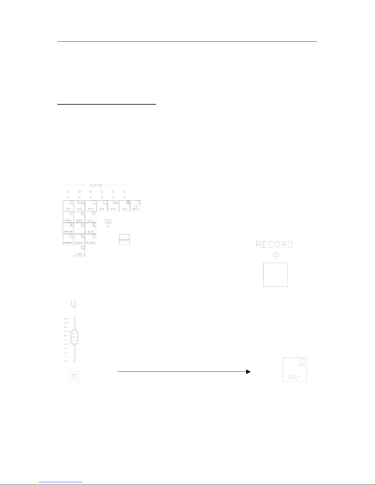
The grouping of keys at the bottom right of the 200 console
is the effects tile.
Select the effect page by toggling the FX page button.
(The LCD screen will display the current effect page)
Press the record key, the “record” ndicating the
console is now in record mode and Press the corresponding
effect’s number key to record that effect. The yellow LED above
that button will start flashing indicating that it is ready to record.
Set the desired fader(s) (while in either one scene or two scene mode) or
scene(s) (while in submaster mode) to the preferred level and then press step
to record that step. The LCD screen will display all relevant information.
Notice that the effect step will advance from 1.01 to 1.02 (with the first digit being the effect
number). Change the fader levels to the desired levels in step 2 and press step to record
that step. Repeat for as many as 99 steps. After recording the steps, select the effect mode
and direction and step time (see below for mode and direction information), then press the
LED will light up i
ready.
Page 22
Page 22 Strand 200 Console Manual
selected effect key, it will record the selections upon exiting from that particular effect’s
recording and the yellow LED will stop flashing.
When finished with effect recording, press the record key again, the console will exit from
record mode and the record LED will turn off.
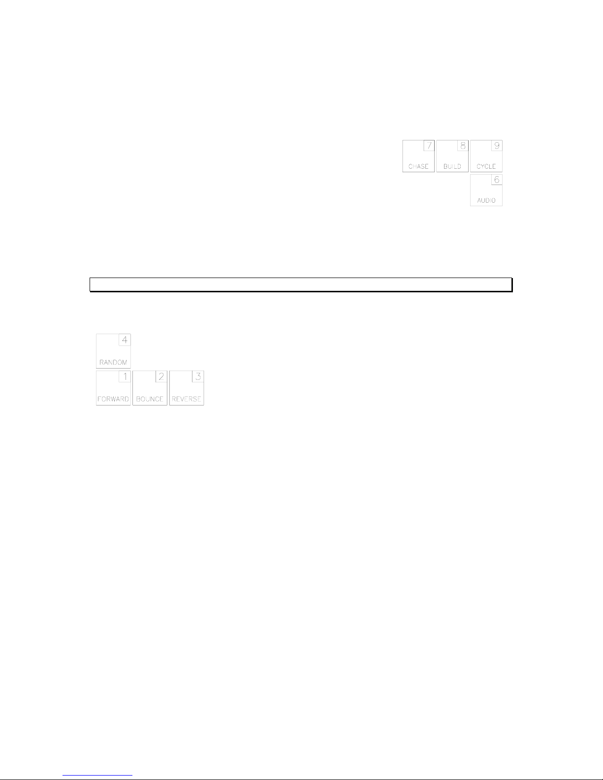
Effect Mode
There are 4 effect modes to choose from…
Chase - the steps will flash in the order set by the direction mode.
Build – the steps will pile on in order set by the direction mode.
Cycle - the steps will fade up and down in the order set by the direction mode.
Audio – will allow an audio signal to trigger effect steps to the beat of the music.
Note: See Audio section in Setup for more information.
Effect Direction
There are 4 effect direction modes to choose from…
Random – the steps will flash in a non-ordered sequence.
Forward – the steps will flash in order from lowest to highest.
Bounce – the steps will flash in order from lowest to highest then back from highest to lowest.
Reverse - the steps will flash in order from highest to lowest.
Additional Information for Effects
• To program another effect, simply repeat the above procedure. Any Yellow LED will
light up for effect numbers that are already recorded.
• To access a scene from a different page in submaster mode, select scene(s) from
page 1 to desired level and then change to page 2 with the page button.
• Note: each step will only allow recording of either multiple channels or scenes. No
mix of scenes and channels is allowed.
• Up to 6 different effects can be played back at the same time.
Page 23
Strand 200 Console Manual Page 23
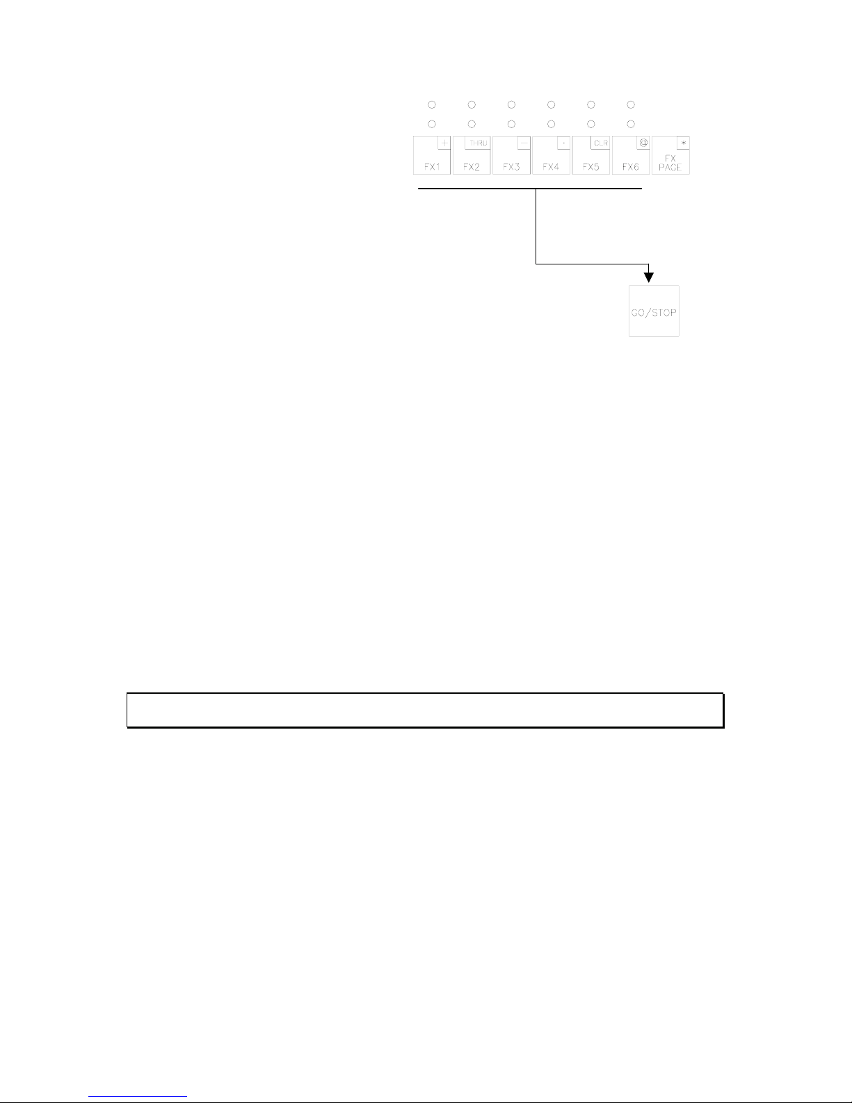
Effects Playback
Each recorded effect will display the
yellow LED above it. To run an effect,
press the effect button that is
requested. The yellow LED above it will
begin flashing. Then press the “Go/stop”
button to start the effect(s). The lower
LED’s will now go off and the upper LED
(red) will be on indicating the effect is
running.
To stop an effect, press the corresponding effect key again. (Remember
to select the correct page first), the yellow LED will be flashing. Then press
“Go/Stop” key again, the selected effect will stop (both red and yellow
LED will turn off).
Additional Information for Effects Playback
• To change the effect mode, direction and step rate for any particular effect while it is
running, select the effect itself followed by the wanted mode, direction and step time,
the effect will immediately change to the new mode and direction. Press effect key
again to exit from change. The effect now will run on the new setting. (note: the
recorded setting will not change).
• During effect playback, the red LED for the running effect(s) will be flashing when the
effect(s) is on the current selected page, to provide the operator easy visual
reference, which effect(s) on which page is actually active.
• The following combinations will be allowed:
o Chase (Random or forward or reverse or bounce or audio)
o Build (forward or reverse or bounce)
o Cycle (forward or reverse or bounce)
Note: See Audio section of Setup to properly configure the console to have an audio source trigger an
effect.
• To step an effect from an audio source, set your effect to chase/audio. (See
instructions for above ). Select the effect as normal (select effect key and press
go/stop button), it will step thru that effect when audio signals within that frequency
range is fed in. Deactivate the effect as usual (select effect key and press go/stop
button).
Page 24
Page 24 Strand 200 Console Manual
Scene Pg: 1 Fx Pg: 2
Preset A: FL B: 00
sFX:20.00Cha For 0.2
Scene FX Setup
Running Effects on Submasters
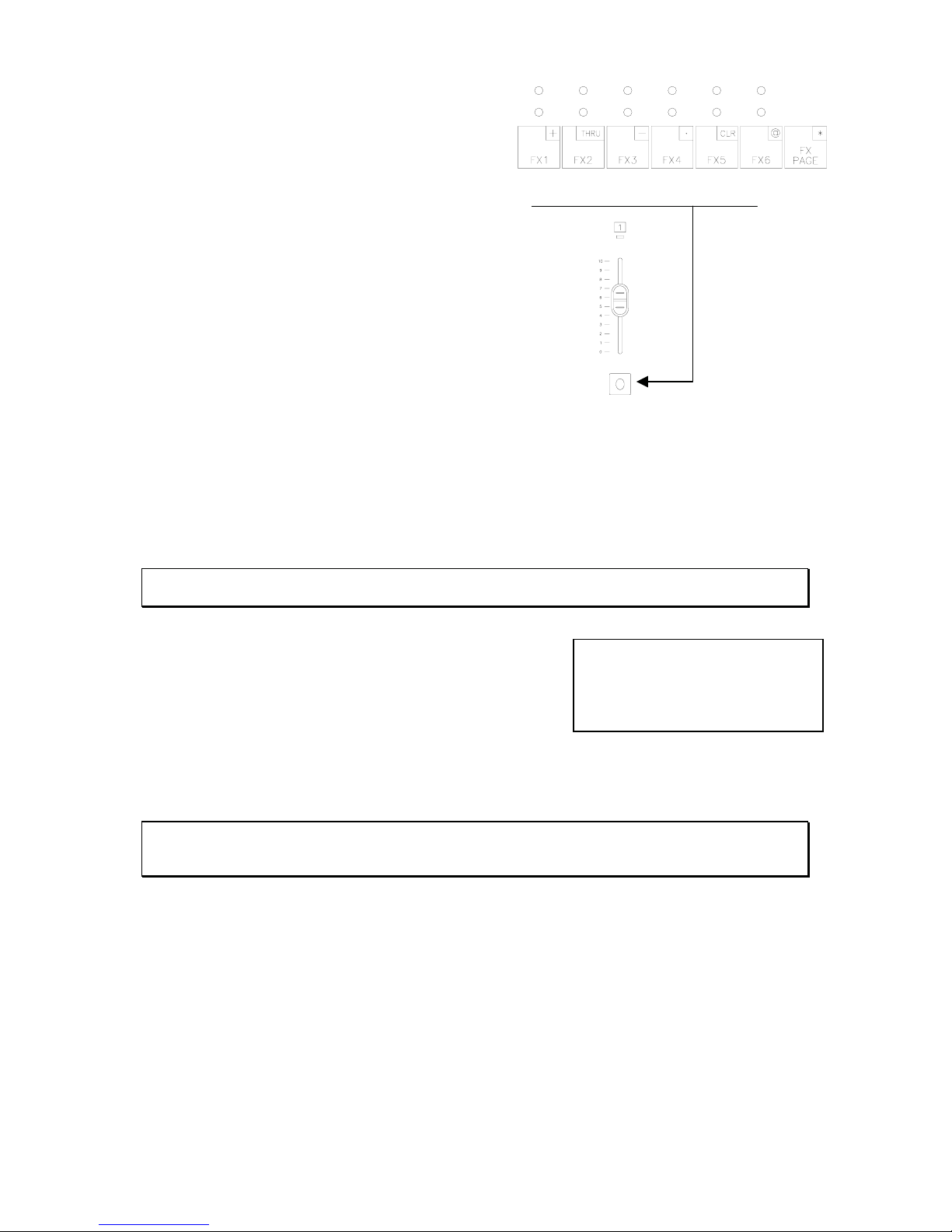
Alternatively, effect(s) can be playback on a
normal fader (only at submaster mode). All
24 effects can only be loaded onto any empty submaster
or submaster with effect. Select the wanted effect, then
press the flash button and hold it for 1 second, the effect is
now loaded into the corresponding fader channel, the
fader LED will now light up with red color indicating this
fader is loaded with the effect.
An effect cannot be assigned to a submaster that already
has a scene recorded into it. Activating the channel fader
will start the effect running.
(Note: Must be in submaster mode for this to occur).
Step time, mode and direction can be changed at any time before or during playback. Press
and hold the corresponding flash button and then move the step rate fader at the same time,
the effect will change to the new step rate, or select a different mode or direction. The mode
and direction will change immediately. Returning the fader to zero will stop the effect.
Note: Unlike the standard effects, any changes made on effects assigned to a submaster will be
recorded even after the fader is returned to zero.
To check any effect’s information that is assigned to a
submaster, press and hold the corresponding flash button
at any time, the LCD display will show the effect’s number
with the mode and step time information if the effect is
running.
(Note: Up to 24 effects can be played back simultaneously from effects on subs. An effect
can not be copied from one sub to another, nor can an effect from the standard effect pages
be copied to more than one sub).
Note: If the console is switched from submaster mode to channel mode during effect playback,
effect(s) will continue and the faders assigned for effect playback will remain at same status until the
fader is returned to zero and will automatically change back to act as a channel fader.
Page 25
Strand 200 Console Manual Page 25
Scene Pg: 1 Fx Pg: 2
Preset A: FL B: 00
Scene FX Setup
1. Edit Effect
2. Delete Effect
3. Effect Fade Time
Esc Confirm
Fx:#.# Step:xx
Ch:01 02 03 04 05 06
LL:xx xx xx xx xx xx
Esc (+/-) Confirm
Fx:1.1 Step:01
Ch:01 02 03 04 05 06
LL:FL 00 00 00 00 00
Esc (+/-) Confirm
Editing an Effect
From the main LCD screen, press F2 for FX.
Notice the cursor flashing over the 1 for edit effect.
Press F3 to Confirm.
The Num Lock LED will now be on and the effect
disabled. Pick the effect number then scroll with the
arrow keys to place the cursor on the step location.
Pick the step to be edited.
Note: The format for Fx: #.# is the first number is the effect page and the second is the effect
number.
Continue scrolling and each channel edited will flash.
Edit the level with either the + or – keys or use the
keypad entry.
When editing is complete press Confirm and it will automatically advance to the next step for
continued editing.
Note: The arrow keys will advance channels quickly.
Page 26
Page 26 Strand 200 Console Manual
Scene Pg: 1 Fx Pg: 2
Preset A: FL B: 00
Scene FX Setup
1. Edit Effect
2. Delete Effect
3. Effect Fade Time
Esc Confirm
1. Del step
2. Del effect
3. Del page effect
Esc Confirm
Fx:#.#
Delete step: xx
Esc (+/-) Confirm
Delete Fx page: #
Effect No.: #
Esc (+/-) Confirm
Effect Delete Options
From the main LCD screen, press F2 for FX.
Notice the cursor flashing over the 1 for edit effect.
Press the right arrow to advance to the delete effect
option and press F3 for Confirm.
At this point, the choices are…
1. Delete a step
2. Delete an effect
3. Delete a page of effects
Each of the three options will continue their key sequences from this point. Repeat above
for each option below.
Note: When Num Lock is on, the effect tile can be used as a numeric keypad for entry.
Delete an Effect Step
The Num lock LED will now be on and the effect
disabled. Pick the effect number then scroll with the
arrow keys to place the cursor on the delete step
location. Scroll for the step that is to be deleted.
Press Confirm to delete.
After confirming, it will return to the same screen but will have the next available step shown.
Repeat above process to make changes and/or delete. Pressing Esc will return to main
display.
Note: The format for Fx: #.# is that the first number is the effect page and the second is the effect
number.
Delete an Effect
Num lock LED will now be on and the effect disabled.
Pick the effect page number then scroll with the arrow
keys and pick the effect number.
Press Confirm to delete. Select YES or NO.
After confirming, the display will return to the same screen but will show the next available
effect. Repeat above process to make changes and delete. Pressing Esc will return to main
display.
Page 27

Strand 200 Console Manual Page 27
Delete Effect
Page: #
Esc (+/-) Confirm
Delete an Effect Page
Num lock LED will now be on and the effect disabled.
Pick the effect page number.
Press Confirm to delete. Select YES or NO.
After confirming, it will return to the same screen but will the next available effect shown.
Repeat above process to make changes and delete. Pressing Esc will return to main display.
Inserting an Effect Step
A step can be inserted into an existing effect. Press the record key, the
“record” LED will light up indicating the console is now in record mode
and ready. Select the effect to be edited (the corresponding yellow LED
will start flashing). Press the + and – keys together for 1.5 seconds, the
effects address will start flashing.
Press + or – to change to the step to be inserted in front of, then record the new step using
the normal step record procedure. After recording the effect LED will stop flashing. Press
the record key to exit the record mode.
Page 28
Page 28 Strand 200 Console Manual
Scene Pg: 1 Fx Pg: 2
Preset A: FL B: 00
Scene FX Setup
1. Edit Effect
2. Delete Effect
3. Effect Fade Time
Esc Confirm
Effect
3. Edit fade time
4. Set fade time to 0
Esc Confirm
Page: #
Effect: #
Fade time: 00.0 sec
Esc (+/-) Confirm
Effect
1. Edit fade time
2. Set fade time to 0
Esc Confirm
Reset effect fade
time to
0.0 sec?
Yes No
Effect Fade Time Options
From the main LCD screen, press F2 for FX.
Notice the cursor flashing over the 1 for edit effect.
Press the right arrow to select the effect fade time
option. Press F3 to Confirm.
Each of the two options will continue their key sequences from this point. Repeat above for
each option below.
Editing Effect Fade Time
Effect fade in time can be set between 0-10 seconds using the edit fade time function. Effect
fade in time will be defaulted at zero when record. Fade out time is not available, an effect
will stop immediately when deactivated.
Press Confirm to edit the fade time.
Num lock LED will now be on and the effect disabled.
Pick the effect page then scroll with the arrow keys to
place the cursor on the effect number. Select the
effect to be edited. Scroll to edit the fade time. The
range is from 00.0 to 10.0 at 1/10
th
second increments.
Reset Effect Fade Time to Zero
Press the right arrow to select the second option
and press Confirm to set the fade time to zero.
Select Yes or No.
Page 29
Strand 200 Console Manual Page 29
Scene Pg: 1 Fx Pg: 2
Preset A: FL B: 00
Scene FX Setup
1. Edit Scene
2. Delete Scene
3. Xfade Start Scene
Esc Confirm
Page:01 Scene:01
Ch:01 02 03 04 05 06
LL:FL 00 00 00 00 00
Esc (+/-) Confirm
Scene Options
From the main LCD screen, press F1 for Scene.
Note: Scene and Submaster are interchangeable terms for this manual.
Edit a Scene
Notice the cursor flashing over the 1 for edit scene.
Press F3 for Confirm.
(The LCD screen will show the corresponding submaster
information).
The channel that is selected will flash. Change
channels using the left and right arrow keys. Change
levels using either the +/ – keys or the numeric keypad.
Note: When Num Lock is on, the effect tile can be used as a numeric keypad for entry.
Press Esc to disregard changes or Confirm to accept.
Press the submaster page button as needed to access
the correct page, then press the flash button for the
correct submaster that needs to be edited.
Page 30
Page 30 Strand 200 Console Manual
1. Edit Scene
2. Delete Scene
3. Xfade Start Scene
Esc Confirm
1. Del one scene
2. Del page scene
Esc Confirm
Scene page: 1
Delete scene: 01
Esc (+/-) Confirm
Delete scene 01?
Yes No
1. Del one scene
2. Del page scene
Esc Confirm
Delete page
Page No.:1
Esc (+/-) Confirm
Delete page 01?
Yes No
Delete Scene Options
Notice the cursor flashing over the 1 for edit scene.
Press the right arrow to advance to the delete scene
option and press F3 for Confirm.
Delete One Scene
Notice the flashing cursor over the delete one
scene option. Press F3 for Confirm.
Press the submaster page button to access the correct
page, then press the flash button for the correct
submaster or scroll using the +/– keys. Press F3 for
Confirm.
Press F2 for Yes or F3 for No.
Delete Page Scene
Notice the flashing cursor over the delete one
scene option. Press the right arrow to advance to
the delete page scene option and press F3 for
Confirm.
Press the +/– buttons to access either page 1 or page 2.
Press F3 for Confirm.
Press F2 for Yes or F3 for No.
Page 31
Strand 200 Console Manual Page 31
1. Edit Scene
2. Delete Scene
3. Xfade Start Scene
Esc Confirm
Xfade start address
Scene:1.01
Esc (+/-) Confirm
Crossfade Start Scene Option
Notice the cursor flashing over the 1 for edit scene.
Press the right arrow to advance to the crossfade start
scene option and press F3 for Confirm.
Use the +/– keys to change the submaster that will
start the crossfade sequence.
Press Esc to disregard changes or Confirm to accept.
Note: The next submaster crossfade will start with the selected scene. Upon completion of
the crossfade, the setting will be automatically reset to 1.01.
Page 32
Page 32 Strand 200 Console Manual
1. Patch
2. Self Test
3. Midi
Esc Next Confirm
Scene Pg: 1 Fx Pg: 2
Preset A: FL B: 00
Scene FX Setup
1. Edit patch
2. Display patch
3. Default patch
Esc Next Confirm
Cmd:_____________________
_
________________________
_
________________________
Esc
Setup
The following is all of the options that can be
accessed through the setup menu.
Press F3 to go into the Setup menu.
Patch
Patch allows you to assign any DMX output address(es) to any channel.
Notice the cursor flashing over the 1 for patch.
Press F3 to Confirm.
Each of the four options will continue their key sequences from this point. Repeat above for
each option below.
Note: The Next command allows the operator to access any option above the third option.
Edit Patch
The console defaults to a one to one patch. This function allows the operator to edit this to
any combination in a command line input format.
Notice the cursor flashing over the 1 for edit patch.
Press F3 to Confirm.
The Num lock LED will now be on and the effect
disabled. The LCD displays an empty command line.
Type in the patch information using the following
format:
Dimmer @ Channel.
For example…for dimmer (output) 12 to be patched to channel 3 then type…
12 @ 3 ENTER *
Note: On consoles that use command lines, the typical key for enter is the asterisk * key. Here that is
the FX Page key with Num Lock enabled.
Page 33
Strand 200 Console Manual Page 33
1. Edit patch
2. Display patch
3. Default patch
Esc Next Confirm
Channel: 01
Dim:001
LL: FL
Esc
Other acceptable commands are…
Key Command Description
+ 1 + 2 @ 5 * Patches dimmers (output) 1 and 2 to channel 5.
Thru 1 > 5 @ 3 * Patches dimmer (output) 1 through 5 to channel 3.
- 1 > 5 – 4 @ 3 * Patches dimmer (output) 1, 2, 3 and 5 to channel 3.
Unpatch a Dimmer
Acceptable commands are…
1 @ * Unpatches dimmer 1.
1 @ 0 * Unpatches dimmer 1.
Thru 1 > 512 @ * Unpatches all dimmers.
Note: Press clear to delete previous entry.
Proportional Patch
Proportional patching will patch a dimmer (output) at any level from zero to full.
Command
Description
1 @ 1 @ 50 Patches dimmer (output) 1 to channel 1 at a maximum level of 50%
Dimmer one’s maximum level is now 50%.
Note: The proportionally patched dimmer output will not rise above proportioned level.
Continue entering all necessary patch information.
Display Patch
This will display all current patch information.
Notice the cursor flashing over the 1 for edit patch.
Press the right arrow key to access display patch
then press F3 to Confirm.
Display patch will start by showing channel one and it’s
dimmer (output) assignment. The screen at the left
shows the default patch information.
The right arrow key will allow the user to step through the patch by channel in numerical
order.
Page 34
Page 34 Strand 200 Console Manual
1. Edit patch
2. Display patch
3. Default patch
Esc Next Confirm
Turn on default
Patch?
Yes No
4. Unpatch all
Esc Next Confirm
Unpatch the
patch table?
Yes No
Default Patch
This will default all patch information back to a one to one status.
Notice the cursor flashing over the 1 for edit patch.
Press the right arrow key to access default patch
then press F3 to Confirm.
Press F2 for Yes or F3 for No.
Unpatch Patch
This will unpatch all dimmer (output) information.
Notice the cursor flashing over the 4 for unpatch all.
Press F3 to Confirm.
Press F2 for Yes or F3 for No.
Note: This will unpatch all dimmers (outputs).
If lights are on at the console, all stage lights will go out.
Note: This can be a very useful way to patch a show.
Start by unpatching all dimmers (outputs), then patch the dimmers to the channels that are needed
for the show.
Additional Information for Patch
Multiple Channel Patch Matrix
A powerful feature of this console is the ability to have any dimmer patched to multiple
channels at once. This allows scenarios like patching a dimmer to a channel to act as a
special. Then patching the same dimmer to a different channel at a proportional level to be
part of a wash.
Page 35
Strand 200 Console Manual Page 35
1. Patch
2. Self Test
3. Midi
Esc Next Confirm
1. All test
2. Display test
3. fader test
Esc Next Confirm
4. Key test
Esc Next Confirm
Self Test
Self Test is a set of on-board diagnostics that will check for problems in all areas of the
console.
Notice the cursor flashing over the 1 for patch.
Press the right arrow key to access self test then
press F3 to Confirm.
1. This will test all of the following items.
2. This will test the display functions on the console.
3. This will test all faders on the console.
4. This will test all buttons on the console.
Follow all prompts on screen to complete the self
tests. For the fader test, activate all faders to full as the screen prompts for each one.
For key test, press all buttons as the screen prompts for them.
Any errors should be reported to your local Strand Distributor, Authorized Service Centre or
Strand representative.
Page 36
Page 36 Strand 200 Console Manual
1. Patch
2. Self Test
3. Midi
Esc Next Confirm
Midi
1. Channel
2. Assign
Esc Confirm
Midi: OFF
Channel:01
Esc (+/-) Confirm
Scene Pg: 1 Fx Pg: 2
Preset A: FL B: 00
Scene FX Setup
MIDI
Musical Instrument Digital Interface is the standard
communications protocol that allows a musical instrument to
send a signal to the 200 console to trigger cues and effects.
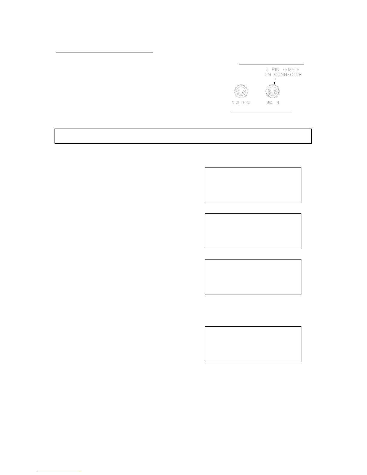
Connect the MIDI generator via a DIN cable to the MIDI IN
input at the back of the console.
Note: MIDI thru allows MIDI commands that are not related to the 200 console to pass through the
console and on to other devices. Connect all MIDI devices accordingly.
Follow these steps to setup the MIDI properly.
Press F3 to go into the Setup menu.
Notice the cursor flashing over the 1 for patch.
Press the right arrow key to access MIDI then press
F3 to Confirm.
Notice the cursor flashing over the 1 for channel.
To assign a MIDI channel press F3 to Confirm.
Enter the MIDI setup and turn MIDI on. Then assign a channel number from the MIDI
generator that will control this 200 console. There are a total of 16 channels (1 –16).
Num lock LED will now be on and any effect(s)
disabled. Notice the cursor flashing over the OFF.
+/– will turn MIDI on. The right arrow key will move
to channel. +/– will allow the selection of the
channel or enter the channel using the numeric
keypad. The options are channels 1 through 16.
Press Confirm when done.
Page 37
Strand 200 Console Manual Page 37
Midi
1. Channel
2. Assign
Esc Confirm
Assign Key:001
To Scene:1.01
Esc (+/-) Confirm
After selecting the channel, go to assign. This will allow you to assign a note (key) to control
a selected scene. All together there are 128 notes (keys) that can be assigned. After
assigned the note, then select the desired submaster (can be a scene or an effect
depending on what is loaded on each sub) that will be activated by that note.
Notice the cursor flashing over the 1 for channel.
Press the right arrow key to access Assign then
press F3 to Confirm.
Num lock LED will now be on and any effect(s)
disabled. Pick the note (key) then scroll with the
arrow keys and pick the scene number.
Note: The scene number refers to the page (to the left of the period) then the submaster (to the right
of the period.
Repeat this scene assignment for every note (key) that is needed.
When playing a midi source instrument, whenever a particular note for that channel is on,
the chosen scene or effect will be outputted. When the note is off or released, the scene or
effect will go fade out or stop.
Page 38
Page 38 Strand 200 Console Manual
4. Audio
5. LCD setting
6. Show file
Esc Next Confirm
1. Patch
2. Self Test
3. Midi
Esc Next Confirm
Scene Pg: 1 Fx Pg: 2
Preset A: FL B: 00
Scene FX Setup
1. High pass
2. Band pass
3. Low pass
Esc Confirm
Audio
Audio allows the console the take an audio signal that will
trigger steps of an effect to the beat of the music.
Plug the audio device to the 200 console via the AUDIO
INPUT 3 Pin XLR connector.
Note: Signal input impedance is 4.7K ohm
The audio setup allows the operator to select bandwidth for the signal. Follow the steps
below…
Press F3 to go into the Setup menu.
Notice the cursor flashing over the 1 for patch.
Press Next to go to the next setup screen.
Notice the cursor flashing over the 4 for audio.
Press F3 to Confirm.
This feature allows the operator to select high pass, band pass or low pass audio filter.
Num lock LED will now be on and any effect(s)
disabled. Notice the cursor flashing over the 1 for
high pass. Use the arrow keys to scroll between the
options on screen.
Press F3 to Confirm.
Note : High pass trigger frequency > 1KHz.
Band pass trigger frequency between 300Hz – 1KHz
Low pass trigger frequency < 300Hz
Page 39
Strand 200 Console Manual Page 39
4. Audio
5. LCD setting
6. Show file
Esc Next Confirm
1. Patch
2. Self Test
3. Midi
Esc Next Confirm
Scene Pg: 1 Fx Pg: 2
Preset A: FL B: 00
Scene FX Setup
Contrast: 99%
Back lit: high
Esc (+/-) Confirm
LCD Settings
The LCD setting allows the operator to control both the contrast and the backlight level.
Follow the steps below…
Press F3 to go into the Setup menu.
Notice the cursor flashing over the 1 for patch.
Press Next to go to the next setup screen.
Notice the cursor flashing over the 4 for audio.
Press the right arrow key to access LCD setting
then press F3 to Confirm.
Change the level using the +/- keys. Navigate with
the left and right arrow keys.
Press F3 to Confirm.
Page 40
Page 40 Strand 200 Console Manual
4. Audio
5. LCD setting
6. Show file
Esc Next Confirm
1. Patch
2. Self Test
3. Midi
Esc Next Confirm
Scene Pg: 1 Fx Pg: 2
Preset A: FL B: 00
Scene FX Setup
1. Save show
2. Load show
3. Del show
Esc Confirm
No card found!
Insert a 32M
Compact Flash
Esc
Show File
The show file options allows the operator to save, load and delete a show file. Follow the
steps below…
Press F3 to go into the Setup menu.
Notice the cursor flashing over the 1 for patch.
Press Next to go to the next setup screen.
Notice the cursor flashing over the 4 for audio.
Press the right arrow key to access Show file then
press F3 to Confirm.
Pick and option for the action that is needed.
Press F3 to Confirm.
No show file functions can be performed without a
compact flash card installed.
Only a 32M compact flash card can be used. The compact flash card has to be dedicated to the 200
console. It cannot share with other devices due to a different file format. The show file cannot be
read on a standard PC.
A 32M compact flash card can be purchased at any local computer or electronics store.
Page 41
Strand 200 Console Manual Page 41
Save show name
As: xxxxxx
Esc <+/-> Confirm
No show name !
Assign as:
Show XX
Esc <+/-> Confirm
Processing
▊▊▊▊▊▊▊▊▊▊
xx %
“Show name”
Load show
01.SHOW01
02.SHOW02
Esc Confirm
Load SHOW01
3. All
4. Patch & setting
Esc Next Confirm
Load SHOW01
1. Scene
2. Effect
Esc Next Confirm
Save Show
Notice the cursor flashing over the 1
st
x, enter a
character (A-Z, 0-9) using the +/- key and move to
the next digit with the > key.
Press F3 to Confirm when done.
If no show name is entered before pressing confirm,
the console will automatically assign an available
show name as “show xx” between show01 –
show30. The number can still be changed if not
used already.
Press F3 to Confirm.
The save show will now start and the display will
indicate the process during save.
After the show is successfully saved, the display will
return to the normal screen.
Note: Up to 30 shows can be stored on a 32M compact flash card.
Please delete unneeded show files before saving if the CF card is full.
Load show
Notice the cursor flashing over the 1
st
show, use
the <> key to select the wanted show and press
F3 to Confirm.
Notice the cursor flashing over the 1 for All. Press
the right arrow key or press F2 key to next page to
select either load all, patch and setting, scene or
effect, then press F3 to Confirm.
Note: Load scene will load all submaster’s contents including effects on subs.
Page 42
Page 42 Strand 200 Console Manual
Processing
▊▊▊▊▊▊▊▊▊▊
xx %
“Show name”
Del show
01. SHOW01
02. SHOW02
Esc Confirm
Del show
SHOW01
Confirm ?
Esc Confirm
Processing
▊▊▊▊▊▊▊▊▊▊
xx %
“Show name”
The selected show information will now be loaded
Onto the console memory and overwrite the existing
data.
Delete show
Notice the cursor flashing over the 1 show name.
Press the right arrow key to access the show file to be
deleted then press F3 to Confirm.
Press confirm again to delete show.
Once confirmed, the delete show file will function
proceed and the display will indicate progress.
Page 43
Strand 200 Console Manual Page 43
4. Audio
5. LCD setting
6. Show file
Esc Next Confirm
1. Patch
2. Self Test
3. Midi
Esc Next Confirm
Scene Pg: 1 Fx Pg: 2
Preset A: FL B: 00
Scene FX Setup
Set buzzer
1. Disable buzzer
2. Enable buzzer
Esc Confirm
7. Set buzzer
Esc Next Confirm
Set Buzzer
The internal buzzer can be either enabled or disabled. When turned on, the buzzer will
sound whenever a illegal key is pressed. Follow the steps below…
Press F3 to go into the Setup menu.
Notice the cursor flashing over the 1 for patch.
Press Next to go to the next setup screen.
Notice the cursor flashing over the 4 for Audio.
Press Next to go to the next setup screen.
Notice the cursor flashing over the 7 for Buzzer.
Press F3 to Confirm.
Select enable or disable Buzzer with <> keys.
Press F3 to Confirm.
The Buzzer’s default is enabled.
Page 44

Page 44 Strand 200 Console Manual
Conclusion
This concludes the instructional manual for Strand’s 200 series console.
Accessories
A video display card is available for the console.
A vinyl cover is available for the console.
Contact your local dealer for price and availability.
A compact flash card can be purchased at your local computer or electronics store.
Page 45
Strand 200 Console Manual Page 45
Appendix A
Control Input
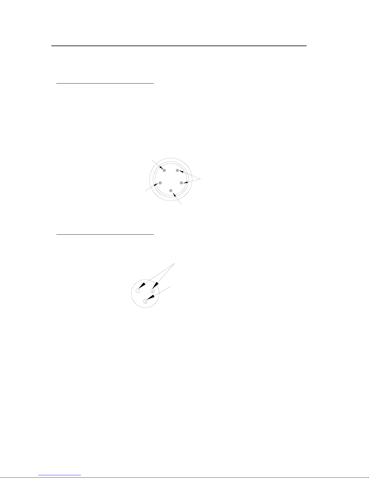
The DMX512 output is a multiplexed digital control signal conforming to USITT specification
DMX512 (1990). Details of this specification are available from USITT on request.
The control input is via a five-pin male XLR type connector. Pin connections are shown in
Figure 9. A five-pin female XLR connector is fitted to allow dimmers (or other DMX
equipment) to be connected together in ‘daisy chain’ fashion.
Audio Input
GROUND
SIGNAL
1
2
3
4
5
SHIELD
NOT CONNECTED
DMX -
DMX +
Page 46

Page 46 Strand 200 Console Manual
Index
A
Accessories ...................................................44
Additional Information for Effects ...............22
Additional Information for Effects Playback 23
Additional Information for Patch..................34
Additional Information for Submaster
Crossfading ...............................................20
Advanced Features........................................21
Appendix A...................................................45
Audio ............................................................38
Audio Input
Quick Guide..............................................11
B
Back Plate .......................................................7
Basic Operation.................................13, 15, 17
Blackout Button
Quick Guide................................................9
C
Changing Submaster Pages...........................19
Channel LED Indicators
Quick Guide................................................9
Compact Flash Slot
Quick Guide..............................................11
Concept
Getting Started ............................................6
Conclusion ....................................................44
Console Power Switch
Quick Guide..............................................11
Control Input.................................................45
Crossfade ......................................................15
Crossfade between Submasters.....................20
Crossfade Start Scene Option .......................31
D
Default Patch.................................................34
Delete an Effect.............................................26
Delete an Effect Page....................................27
Delete an Effect Step ....................................26
Delete One Scene..........................................30
Delete Page Scene.........................................30
Delete Scene Options....................................30
Delete show ..................................................42
Dipless Manual Crossfade ............................ 16
Display Patch................................................ 33
DMX Output
Quick Guide.............................................. 11
DMX512....................................................... 45
E
Edit a Scene .................................................. 29
Edit Patch...................................................... 32
Editing an Effect........................................... 25
Editing Effect Fade Time .............................28
Effect Delete Options ...................................26
Effect Direction ............................................22
Effect Fade Time Options............................. 28
Effect Mode .................................................. 22
Effects........................................................... 21
Effects Playback ...........................................23
Effects Tile
Quick Guide.............................................. 10
F
F1
Function Keys in Quick Guide ................... 9
F2
Function Keys in Quick Guide ................... 9
F3
Function Keys in Quick Guide ................... 9
Face Plate........................................................ 7
Fader Flash Buttons
Quick Guide.............................................. 10
Flash Level
Quick Guide.............................................. 10
Flash Mode
Quick Guide.............................................. 10
Function Keys
Quick Guide................................................ 9
G
Getting Started................................................ 6
Go / Stop Button
Quick Guide.............................................. 10
Grand Master
Quick Guide................................................ 9
Page 47

H
Hold ..............................................................14
Hold Button
Quick Guide................................................9
I
Index .............................................................46
Inserting an Effect Step.................................27
L
Layout .............................................................8
LCD Screen
Quick Guide................................................9
LCD Settings.................................................39
Load show.....................................................41
M
Mechanical & Environmental Data
Getting Started ............................................6
MIDI .............................................................36
MIDI Input
Quick Guide..............................................11
MIDI Thru
Quick Guide..............................................11
Mode Button
Quick Guide................................................9
Multiple Channel Patch Matrix.....................34
N
Navigation Keys
Quick Guide................................................9
Number Lock Indicator
Quick Guide..............................................10
O
Offices and Service Centers............................3
Operation ......................................................13
Ordering Information
Getting Started ............................................6
Quick Guide.............................................. 11
Preset A Master
Quick Guide.............................................. 10
Preset B Master
Quick Guide.............................................. 10
Programming an Effect................................. 21
Proportional Patch ........................................33
Q
Quick Guide.................................................... 9
R
Record Button
Quick Guide................................................ 9
Recording Submasters .................................. 18
Recording Submasters on Page 2 .................19
Reset Effect Fade Time to Zero.................... 28
Running Effects on Submasters.................... 24
S
Save Show ....................................................41
Scene A Faders
Quick Guide................................................ 9
Scene B Faders
Quick Guide.............................................. 10
Scene Options ............................................... 29
Scenes ........................................................... 11
Self Test........................................................ 35
Set Buzzer.....................................................43
Setup ....................................................... 12, 32
Show File...................................................... 40
Single Scene Mode ....................................... 13
Split Time Faders
Quick Guide................................................ 9
Standards Compliance
Getting Started............................................ 6
Step Rate Fader
Quick Guide................................................ 9
Submaster Mode ........................................... 17
Submaster Page Button
Quick Guide.............................................. 10
Submaster Pages ........................................... 19
Submasters.................................................... 11
Strand 200 Console Manual Page 47
P
Patch..............................................................32
Power Connector
T
Table of Contents............................................ 4
Terminology Notes ....................................... 11
Page 48

Time Fades....................................................16
Time Fades for Hold .....................................14
Two Scene Mode ..........................................15
Getting Started............................................ 6
Unpatch a Dimmer........................................ 33
Unpatch Patch............................................... 34
U
Unpack the Console
W
Welcome......................................................... 2
Page 48 Strand 200 Console Manual
 Loading...