


Strand Lighting Inc.
6603 Darin Way, Cypress, CA 90630, USA
Tel: +1 714 230 8200 Fax: +1 714 230 8173
Strand Lighting Europe Ltd.
Unit 2, Royce Road, Fleming Way, Crawley, West Sussex. United Kingdom
Tel: + 44 1293 554 010 Fax: + 44 1293 554 019
Strand Lighting Asia
20/F Delta House, 3 On Yiu Street, Shatin, N.T. Hong Kong
Tel: + 852 2757 3033 Fax: + 852 2757 1767
www.strandlighting.com
The material in this manual is for information purposes only and is subject to change without notice.
Strand Lighting assumes no responsibility for any errors or omissions which may appear in this manual.
For comments and suggestions regarding corrections and/or updates to this manual, please contact your
nearest Strand Lighting office.
El contenido de este manual es solamente para información y está sujeto a cambios sin previo aviso.
Strand Lighting no asume responsabilidad por errores o omisiones que puedan aparecer. Cualquier
comentario, sugerencia o corrección con respecto a este manual, favor de dirijirlo a la oficina de Strand
Lighting más cercana.
Der Inhalt dieses Handbuches ist nur für Informationszwecke gedacht, Aenderungen sind vorbehalten.
Strand Lighting uebernimmt keine Verantwortung für Fehler oder Irrtuemer, die in diesem Handbuch
auftreten. Für Bemerkungen und Verbesserungsvorschlaege oder Vorschlaege in Bezug auf Korrekturen
und/oder Aktualisierungen in diesem Handbuch, moechten wir Sie bitten, Kontakt mit der naechsten
Strand Lighting-Niederlassung aufzunehmen.
Le matériel décrit dans ce manuel est pour information seulement et est sujet à changements sans préavis.
La compagnie Strand Lighting n'assume aucune responsibilité sur toute erreur ou ommission inscrite dans
ce manuel. Pour tous commentaires ou suggestions concernant des corrections et/ou les mises à jour de ce
manuel, veuillez s'll vous plait contacter le bureau de Strand Lighting le plus proche.
Information contained in this document may not be duplicated in full or in part by any person without
prior written approval of Strand Lighting Inc. Its sole purpose is to provide the user with conceptual
information on the equipment mentioned. The use of this document for all other purposes is specifically
prohibited. Certain features of the equipment described in this document may form the subject of patents
or patent applications.
Document Number: 2-450199-010
Version as of: December 11, 2008
Vision.net Pushbutton Station Installation & Operation Guide
©2008 Philips Group. All rights reserved.

Pushbutton Station Installation & Operation Guide
TABLE OF CONTENTS
Preface ....................................................................................................................................... 2
About this Guide ...............................................................................................................2
Vision.net System Overview ............................................................................................. 2
Quick Start ........................................................................................................................ 2
8-Button Remote Station Overview .................................................................................. 3
Specifications ............................................................................................................................ 3
Installation ................................................................................................................................. 4
Installation Steps ............................................................................................................... 4
Vision.net Station Operation Modes ......................................................................................... 5
Standard Mode ..................................................................................................................5
Configurable Mode ........................................................................................................... 5
Operation ................................................................................................................................... 9
Selecting a Scene ..............................................................................................................9
Recording a Scene ............................................................................................................. 9
Troubleshooting ........................................................................................................................ 9
Standard Mode ..................................................................................................................9
Configurable Mode ........................................................................................................... 9
IMPORTANT INFORMATION. PLEASE READ!
This unit is intended for installation in accordance with the National Electric Code® and local
regulations. It is also intended for permanent installation in indoor applications only. Before
any electrical work is performed, disconnect power at the circuit breaker or remove the fuse to
avoid shock or damage to the control. It is recommended that a qualified electrician perform
this installation.
1

Installation & Operation Guide Pushbutton Station
PREFACE
About this Guide
The document provides programming and installation instructions for the following Vision.net
products:
• Vision.net Pushbutton Stations (63021VN, 63022VN, 63024VN & 63028VN)
Please read all instructions before installing or using this product. Retain this guide for future
reference.
Vision.net System Overview
The Vision.net System is designed to control architectural lighting by distributing both power
and intelligence. The system provides processing power and control at each respective
Pushbutton, Fader or Touch Screen Station, eliminating the need for a central processor.
Fader Stations provide individual control for up to 15 channels, 8 scenes plus "Off," all with
adjustable fade times. By combining Vision.net Fader Stations, Vision.net Button Stations and
Vision.net Touch Screens, the system provides remote access to scenes, Master Raise/Lower
control, Multi-room partition control, or Master Station Lockout.
Vision.net Stations are compatible with Strand Lighting A21, R21, C21 and EC21 Dimming
Cabinets.
Vision.net products are controlled by the Vision.net System protocol. All Vision.net control
devices must be connected to the Vision.net system and given a unique ID (or address) in
order to interact properly. The ID identifies the device on the network and allows the device to
avoid network collisions when transmitting data.
Quick Start
To get the 8-Button Remote Station up and running quickly, use the following checklist:
Step 1. Install unit (refer to "Installation" on page 4).
Step 2. Connect to Vision.net Network
Step 3. Set the mode using the Vision.net Designer software
The unit should now be ready for operation.
Note: Panels are pre-configured at the factory with the ID of 1 and are set to activate Scenes 1
to 8 in Room 1 of your Vision.net system.
2

Pushbutton Station Installation & Operation Guide
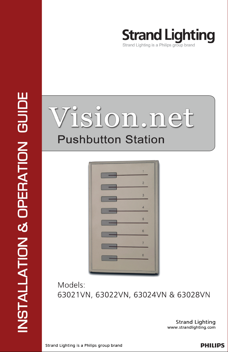
8-Button Remote Station Overview
The Vision.net Button Remote Stations (63021VN, 63022VN, 63024VN & 63028VN) are
used in combination with other Vision.net panels to provide quick, one-touch access to up to 8
Preset Scenes.
The 8- Button Remote Station features illuminated pushbuttons which correspond to Scenes
1-8. The following diagram provides an overview of 8-Button Remote Station controls in a
typical configuration:
SPECIFICATIONS
Electrical
• Input Power: +18-26 VDC (powered from Vision.net network)
• Current: 20mA
• Temperature:
- Storage: -25° to 85° C
- Operating: 0° to 40° C
- Relative Humidity: 30-90% (non-condensing)
Communications
• Vision.net Protocol
3

Installation & Operation Guide Pushbutton Station
INSTALLATION
The Vision.net Network consists of a single CAT5e cable connecting all modules in a daisy
chain manner. All units connect to the network using a 9-pin plug-in connector (included).
Installation Steps
Step 1. Unpack unit and inspect for any signs of shipping damage. Ensure that two
mounting screws and Allen Key are included.
Step 2. Release the Sub Plate from the panel by loosening the set screw at the base of the
panel with the supplied Allen Key.
Step 3. Connect Sub Plate to a wall box using the two supplied mounting screws.
Step 4. Connect Vision.net Network Cable to 9-pin connector at back of the panel Interface.
Note: Use only wire specified on
system drawings. All wiring must
be daisy chained only.
Step 5. Connect the trim panel to the sub frame and fix in place with the set screws.
Note: The back box shall be 3.500
inches deep, sized for the
appropriate station gang width.
Back box must be grounded. All
Back boxes shall be provided by
others.
4

Pushbutton Station Installation & Operation Guide
VISION.NET STATION OPERATION MODES
Vision.net stations can be set in either Standard Mode or Configurable Mode. The default
setting for the station is assigned to Room 1 in Standard Mode.
A station, configured in either Standard or Configurable Mode, can be reset to the factory
default as follows:
Step 1. Unplug the station from the network.
Step 2. Re-plug the station while pressing and holding any button for at least 3 seconds.
Standard Mode
In Standard Mode, you can control up to 31 rooms, each with Presets 1 to 8.
Note: Standard Mode requires either 8-button stations or Slider Preset stations in each room.
Assigning a station to a room:
Step 1. Reset the station to the factory default, Room 1 as described above.
Step 2. Press and hold Buttons 3 and 6 for 3 or more seconds to enter programming mode.
When in programming mode, all button LED’s are off, except for Button 1 which
should be flashing. All other Stations on the network will blink with either one or
two quick blinks every 2 seconds
Step 3. Pressing Button 2 increases the assigned room number by 1. You can press Button 2
a maximum of 30 times assigning it up to room 31.
Step 4. Stations with a single blink every 2 seconds are already set to this room. Pressing
and holding any button on a blinking station that has the 2 blink pattern for 3 or
more seconds, will set it to the current room. It will blink in with the single blink
pattern in confirmation.
Step 5. Complete the programming mode by pressing and holding Button 1 on the first
station.
Configurable Mode
In Configurable Mode, Vision.net products are controlled by the Vision.net System protocol.
All Vision.net devices must be given an ID (or address), which identifies the device on the
network and allows it to avoid network collisions when transmitting data.
Standard IDs are in the range of 1 to 1000. The Network ID for the panel will be pre-assigned
at 1 by the factory and will need to be set to the required address and programmed as required
for your installation.
Vision.net stations are programmed and have their ID’s set using the Vision.Net Designer
software (supplied separately, part number #67518). To obtain the Vision.Net Designer
software, please contact your local Strand Lighting Distributor.
5

Installation & Operation Guide Pushbutton Station
Setting the Station's Vision.net Network ID:
Step 1. Connect the PC running the Vision.net Designer software to the Vision.net Network
via the Vision.net RS232 station, using an RS232 lead. Alternatively you can
connect to the Vision.net network using a Bluetooth interface. Please contact your
local Strand Lighting Office for more details on this interface.
Step 2. Set Vision.net Designer to work "On Line."
Step 3. Select or add the required station from the
Network Tree and press the Station ID button.
Step 4. Select Set Station ID and the LED’s of all
unassigned stations will flash.
Step 5. Press and Hold any button on the required
station for 3 seconds and the station's ID will be
set.
Changing the Vision.net Network ID:
Step 1. Connect the PC running the Vision.net Designer software to the Vision.net Network
via the Vision.net RS232 station, using an RS232 lead. Alternatively you can
connect to the Vision.net network using a Bluetooth interface. Please contact your
local Strand Lighting Office for more details on this interface.
Step 2. Set Vision.net Designer to work "On Line."
Step 3. Select or add the required station from the
Network Tree and press the Station ID button.
Step 4. Select Change Station ID and the LED's of all
stations will flash.
Step 5. Press and Hold any button on the required
panel for 3 seconds and that Station will be set
to the current station ID. Any other station that is currently set to that ID will have
its ID cleared.
6

Pushbutton Station Installation & Operation Guide
Saving the Configuration to the Station:
Step 1. Connect the PC running the Vision.net Designer software to the Vision.net Network
via the Vision.net RS232 station, using an RS232 lead. Alternatively you can
connect to the Vision.net network using a Bluetooth interface. Please contact your
local Strand Lighting Office for more details on this interface.
Step 2. Set Vision.net Designer to work "On Line."
Step 3. Select or add the required station from the Network Tree and set the required mode
for each button as desired.
Step 4. Select Upload & OK and the configuration set in the Vision.net Designers software
will be saved to the station.
Note: If the upload process fails, a warning will appear advising that the communications to
the panel are unreliable. If this occurs, check that you have a good connection to the Vision.net
network and that there is a panel with the ID that you are trying to download the information
to. Refer to "Troubleshooting" on page 9.
7

Installation & Operation Guide Pushbutton Station
Downloading the current Configuration from the Station:
Step 1. Connect the PC running the Vision.net Designer software to the Vision.net Network
via the Vision.net RS232 station, using an RS232 lead. Alternatively you can
connect to the Vision.net network using a Bluetooth interface. Please contact your
local Strand Lighting Office for more details on this interface.
Step 2. Set Vision.net Designer to work "On Line."
Step 3. Select or add the required panel from the Network Tree and press the Get
Configuration from Station button. The current configuration loaded in that panel
will be downloaded to Vision.net Designer.
Once the information has been downloaded the current configuration of the station will be
displayed.
Note: If the download process fails, a warning will appear advising that the communications
to the panel are unreliable. If this occurs, check that you have a good connection to the
Vision.net network and that there is a panel with the ID that you are trying to download the
information to. Refer to "Troubleshooting" on page 9.
8

Pushbutton Station Installation & Operation Guide
OPERATION
Selecting a Scene
Typically an 8-button station provides access to eight Scenes (1-8). To select a Scene, press the
appropriate button on the keypad. The LED will illuminate to show the selected scene.
Recording a Scene
If the 8-button station does not have the "Disable Press-Hold Learn" feature enabled, pressing
and holding the button on for 3 or more seconds will record the current state into the scene.
The LED for the scene will then illuminate to confirm that it has been recorded. Note: If other
actions have been programmed into the panel, it is possible that LED may not illuminate.
TROUBLESHOOTING
In order to determine if a Vision.net Network device is communicating, a network test signal
can be sent.
Standard Mode
Step 1. Press and hold Buttons 3 and 6 for 3 or more seconds to enter programming mode,
When in programming mode, all button LED’s are off, except for Button 1 which
should be flashing.
Step 2. All other stations assigned to the same room will flash.
Step 3. Cancel programming mode by pressing and holding Button 1 on the same station.
Configurable Mode
The network test signal can be sent using the Vision.net Designer software.
Station Identification:
Step 1. Connect the PC running the Vision.net Designer software to the Vision.net Network
via the Vision.net RS232 station, using an RS232 lead. Alternatively you can
connect to the Vision.net network using a Bluetooth interface. Please contact your
local Strand Lighting Office for more details on this interface.
Step 2. Set Vision.net Designer to work "On Line."
Step 3. Select the required panel from the Network
Tree and press the Station ID button.
Step 4. Select Flash Station and the LED's of the
selected station will flash.
9

Part No. 2-450199-010
 Loading...