

Page 1
7.1.2
PRODUCT DATA
A Guide to Multidim
The Multidim range of modular, plug-in dimmers can build into an integrated system
to control a mixture of lighting loads.
Multidim is designed for use with remote pushbutton (preset) or manual (slider) control
stations. Manual control allows continual adjustment of the lighting to suit the ambience,
while the dimmer’s preset capabilities provide the opportunity to set up four predetermined
light levels. Operation of remote pushbutton control stations will then cause the dimmer
output to fade automatically to these levels at a pre-determined fade rate.
Each plug-in module is supplied complete with its own base socket, which fixes directly onto
a wall or Strandrail, to which all load, supply and control wiring terminates. Modules can be
installed individually or in groups. When installed in groups, adjacent base sockets form two
trunking sections for separately routing the control and mains cables to and from the
dimmers.
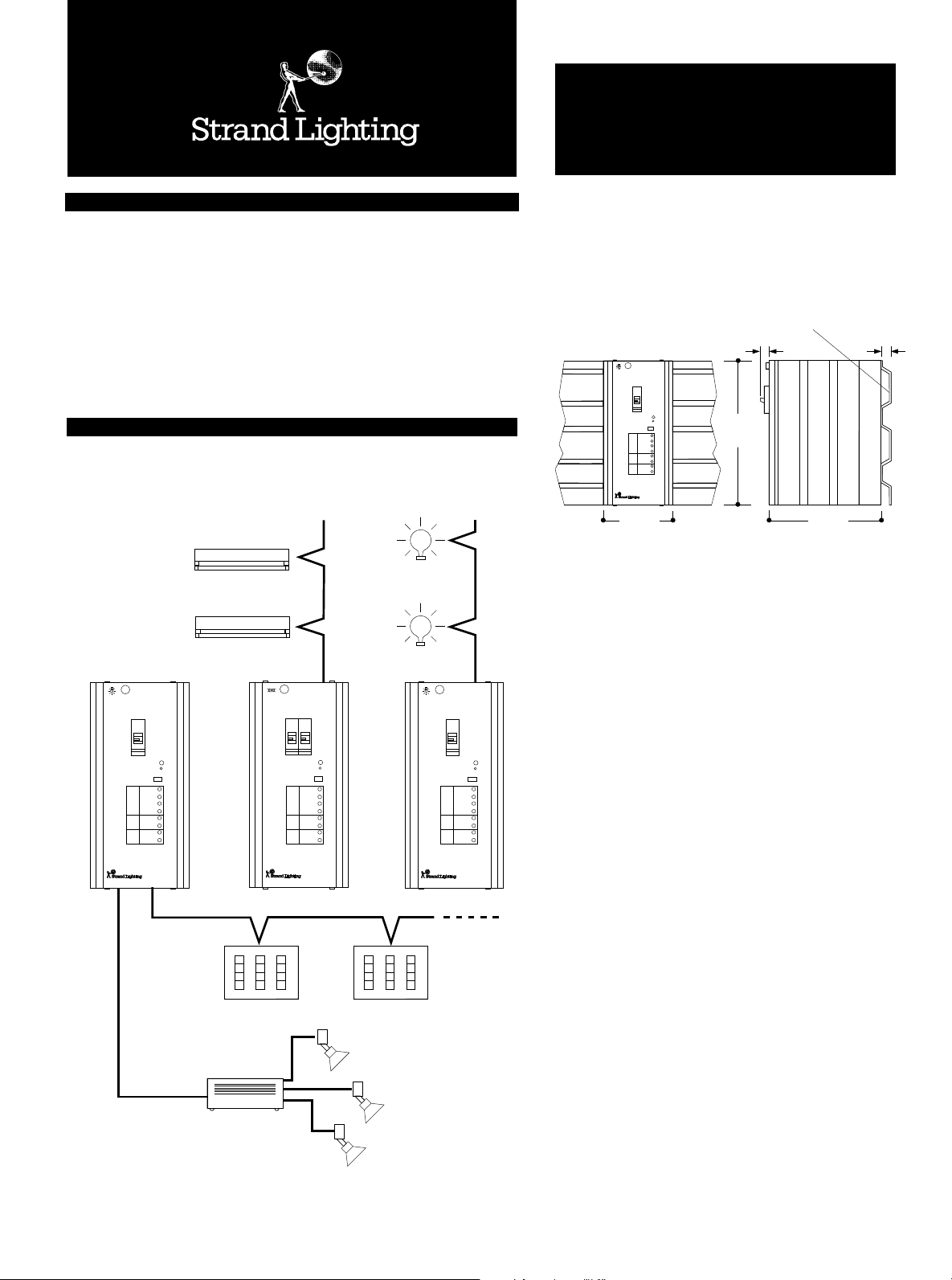
Multidim Typical Schematic
Tungsten and
Tungsten Halogen
Fluorescent
Lighting
Lighting
ARCHITECTURAL
MULTIDIM
™
Plug-In Modular Dimmers
Weights
6A 3.5kg
16A 4.0kg
32A 5.5kg
MULTIDIM
16A TUNGSTEN &
INDUCTIVE DIMMER
FADE RATE RANGE: SLOW
RESTART MODE: PRESET O
PRESETS
FADE
RATE
TOP SET
TRIM
BOTTOM SET
135mm
Strandrail
13mm
FAST
PRESET A
A
B
C
D
UP
DOWN
270
mm
210mm
Standrail
Width 945mm
Height 270mm
Depth 15mm
Weight 3kg
15mm
TUNGSTEN
MULTIDIM
MULTIDIM
16A TUNGSTEN &
INDUCTIVE DIMMER
FADE RATE RANGE: SLOW
RESTART MODE: PRESET O
A
B
PRESETS
C
D
UP
FADE
RATE
DOWN
TOP SET
TRIM
BOTTOM SET
FLUORESCENT
FAST
PRESET A
MULTIDIM
MULTIDIM
16A FLUORESCENT
DIMMER
FIXED VARIABLE
FAST START: OFF
HEATER SAVE: OFF
PRESETS
FADE
RATE
TRIM
BOTTOM SET
Low Voltage Control Wiring
3 Gang Preset
Control Station
Transformer
ENABLE
ENABLE
A
B
C
D
UP
DOWN
TOP SET
TUNGSTEN
MULTIDIM
3 Gang Preset
Control Station
Low Voltage
Lighting
MULTIDIM
16A TUNGSTEN &
INDUCTIVE DIMMER
FADE RATE RANGE: SLOW
RESTART MODE: PRESET O
PRESETS
FADE
RATE
TRIM
BOTTOM SET
Busbar Connect Set
(Each connector)
Width 35mm
Height 20mm
Depth 8mm
Weight 0.2kg
FAST
PRESET A
A
B
C
D
UP
DOWN
TOP SET
Typical applications include:Hotels, Restaurants, Churches, Meeting Rooms, Museums,
Galleries & Auditoria.
● Versions suitable for tungsten and transformer-fed or
fluorescent loads.
● Module ratings of 6, 16, and 32 Amps: each dimmer fitted
with load-protecting MCB(s).
● ‘Fast-start’ feature for dimming h.f. electronic dimmable
ballasts.
● Accessories to simplify installation.
● Genuine ‘load independent’ hard-firing of thyristors ensures
stable output for all types of dimmable load.
● Four adjustable preset levels and separate
Up and Down fade rates for use with
remote pushbutton control stations.
● Suitable for use with manual (fader) control stations or any
analogue (0 to ± 10 volt) control system.
● “Panic” facility for turning dimmers to full in an emergency.
Page 2

PAGE 2 © Strand Lighting MULTIDIM PLUG-IN MODULAR DIMMERS Version 1.0
Specifications
GENERAL
1 The dimmer shall be a plug-in modular unit that can be used individually, or built into an
integrated system to control a mixture of lighting loads.
2 Each dimmer shall be suitable for a 220/240 Volt ac 50/60 Hz single phase, neutral and
earth supply.
3 The dimmer module shall be convection cooled, with ventilation slots provided top and bottom.
4 The dimmer shall be of steel construction with finned (according to rating) extruded
aluminium side panels for additional heat dissipation.
The finish shall be powder coat “Dusty Grey” (Staubgrau - RAL 7037 9090/43231)
5 The dimmer shall dissipate a maximum 2% of the connected load as heat.
6 Each dimmer shall be supplied with a base unit to which all load, supply and control wiring
terminates and into which the dimmer module is plugged.
7 Each module shall be fully enclosed. It shall not be necessary to gain access to the module
for installation or commissioning.
8 Modules shall be available for tungsten/inductive or fluorescent loads with ratings of 6,
16 and 32 amps.
9 Each base unit shall be keyed to prevent a module of the incorrect rating being inserted.
10 The dimmer shall be secured to its base unit with a knurled locking screw accessible from
the front of the dimmer module.
11 It shall be possible to remove side access panels on adjacent base units to form a
segregated load/supply and control wire trunking.
12 The base unit shall contain compression terminals accepting up to 10 mm2 cable for load
and supply wiring.
13 The base unit shall contain a 16 way terminal strip accepting up to 1.5 mm2 signal cable
for control termination.
14 The base shall include internal phase, neutral and earth busbars which can be used to
distribute power to adjacent dimmers using optional Busbar Connect Sets rated at 32 Amps.
Two additional access panels shall be provided to gain access to the internal busbars.
15 Each dimmer module shall have back-to-back thyristors which shall be genuinely hard fired
from a firing circuit which operates independent of load current.
16 The rise time of the dimmer output current shall be limited by substantial varnish
impregnated torroidal filters.
17 Tungsten dimmers shall have a single MCB for load and dimmer protection, fluorescent
dimmers shall have an additional MCB for the heater circuit used on 4 wire dimming ballasts.
‘Panic’ Facility
A maintained connection between terminals 1 and 16 will hold the dimmer at full.
23 Each dimmer module shall support the following front panel facilities:
A red LED indicator showing that power is applied to the dimmer.
SWITCH SETTINGS:
Restart mode: Dimmers shall have a user selectable power-up condition. Select either
Preset A or Preset O as preferred. Preset O shall be selected for all non-pushbutton
control applications.
Fade Rate Range: Shall select either Fast (0.3 to 30 seconds) or Slow
(3 to 300 seconds) range for manually adjusted up and down fade rate.
Note: Fade rate only applies for pushbutton control.
Fluorescent modules shall have the following additional switch settings:
Heater Save: Shall automatically disconnect the fluorescent heater supply LF when
dimmer is at full.
Fast Start: Special feature for dimmable high frequency electronic ballasts to ensure
correct starting of lamp(s)
MANUAL ADJUSTMENTS:
Each dimmer shall be supplied with a tool for making manual adjustment:s:
Presets: Level adjustments for the four presets A, B, C and O. Applicable only when
pushbutton control stations are used, or when setting an appropriate level for the
“Restart” function.
Fade Rate: Separate settings for up and down fade speed.
Trim: Top and bottom set adjustments determine the maximum and minimum dimmer
output
MASTER/SLAVING:
24 It shall be possible via control wiring to connect any number of dimmers as ‘slaves’ to a
designated ‘master’ dimmer so that they respond in unison to a single control signal.
This is useful in cases where a large load is to be dimmed, or where the overall load is to be
split across more than one phase.
When a manual control station is used, a ‘master’ and its ‘slaves’ shall all respond to a single
manual fader level. When pushbutton control is used, ‘slaves’ shall fade to the preset levels set
on the ‘master’ dimmer.
FLUORESCENT DIMMERS:
18 An internal mechanical relay shall be provided to switch on the LF (cathode heater) output
when required for 4-wire systems.
For dimmable high frequency electronic ballasts (where the LF output is not required), a
switch selectable “Fast Start” facility shall be provided to ensure the correct starting of the
lamp(s).
“Fast-start” shall act each time the control is raised from ‘off’ to strike the lamps at around
45% for 1 or 2 seconds before settling smoothly to the control setting.
CONTROL
19 Each dimmer shall provide a -15V dc supply at a maximum of 100mA suitable for
powering remote pushbutton or manual control stations.
20 A range of pushbutton and manual fader control stations shall be available in various
configurations for direct connection to the appropriate control terminal in the dimmers base unit.
21 An optional Photocell Head and Amplifier Setting Panel shall be available for providing
continuous control of the dimmer output in one of 3 modes:-
a Constant Light: This shall provide closed loop control of the dimmer output to
maintain the ambient light level.
b Positive Light Correction: The output of the dimmer shall decrease as light on the
sensor increases.
c Negative Light Correction: The output of the dimmer shall decrease as light on the
sensor decreases.
22 It shall be possible to interface external control equipment to the dimmers as follows:
ANALOGUE CONTROL
Control terminal number 3 in the base shall accept a 0 to ± 10 volts control signal with
respect to the dimmer’s technical earth (terminal 16).
PUSHBUTTON CONTROL
Presets are selected by momentary connection from technical earth (16) to the following
terminals : -
Preset O: Terminal 9 Preset C: Terminal 8
Preset B: Terminal 7 Preset A: Terminal 6
Stop function : Terminal 10
The Stop function shall stop any pushbutton activated fade and hold the lighting at the
current level until another preset is selected.
Note: Pushbutton and analogue control work internally on a “highest level takes
precedence” basis and so the two forms of control are not usually combined on a single dimmer.
ELECTRICAL SUPPLY
Multidim modules shall be suitable for 220/240 Volts AC, 50/60Hz single phase, neutral &
earth.
CABLE SPECIFICATION
Control stations specifically designed for use with Multidim shall operate via low voltage (15V)
dc signals. The cable between dimmer and control station(s) shall be colour-coded multicore
signal cable typically 7/0.2mm, though other types may be used.
The routing for this cable shall avoid proximity with mains cables, in particular those feeding
equipment likely to induce interference (eg. Cinema projectors, HMI lighting etc.).
Maximum length of cable run: 1000 metres.
Refer to the Control Station Data Sheets or the Multidim Installation Instructions for the
number of conductors required for each station type.
DOCUMENTATION
Each Multidim shall be supplied complete with an Installation Instruction Booklet.
STANDARDS
Electrical safety in accordance with IEC 65/BS415
RFI suppression complies with BS800 and VDE 0875 level N, supply level G (load and
control). Rise time of output limited by substantial varnish impregnated torroidal filters.
ENVIRONMENTAL SPECIFICATION
For dimmers, control stations and other associated equipment, the following
recommendations shall apply:
Ambient Temperature extremes 0 - 35° Celsius
To be installed in a position with adequate ventilation allowing for heat dissipated by each
dimmer (up to 2% of the connected load).
Relative Humidity 10 - 90% non condensing
General conditions Office level cleanliness.
Interior use only.
Care shall be taken to avoid sitting the dimmer module in a noise sensitive area, as dimmers
emit low level humming sound.
The dimmers are designed for permanent installation, fixed to a wall or other similar
non-inflammable surface.
Page 3
Version 1.0 © Strand Lighting MULTIDIM PLUG-IN MODULAR DIMMERS PAGE 3
Choice of Module
The selection of the appropriate dimmer module is dependant on two factors:
(i) Type of load - Tungsten, Fluorescent, Low Voltage, Neon and Cold Cathode.
Tungsten Multidim is suitable for low voltage transformer-fed loads, high voltage transformer
fed loads such as Neon and Cold Cathode, as well as mains voltage tungsten or tungstenhalogen lamps.
Fluorescent Multidim is suitable for dimming luminaires with either 38mm diameter (T12),
26mm diameter (T8), or certain 4-pin Compact Fluorescent lamps, when fitted with
compatible dimmable control-gear (See 'Fluorescent Dimming' Section for details).
(ii) Size of load - The guidelines below should be used to select the appropriate 6, 16 or 32
Amp dimmer capacity required. These guidelines take into account the derating factors for
low voltage loads, and ballast type for fluorescent loads.
For mains voltage loads, the module’s stated MCB rating indicates the maximum loading
under normal conditions of supply and ambient temperature. It is normally advisable to
derate by a small margin to allow for supply fluctuations.
Transformer-fed loads such as low voltage lighting, cold cathode, or neon can be dimmed
within safety guidelines. The transformers should be of a type suitable for phase control
dimming, which normally include thermal protection. For further details see Strand Lighting
Fact Sheet No. 5, “A Guide to Installation and Dimming of Low Voltage Lighting”.
Tungsten Multidim’s are suitable for these loads, but they must be de-rated to allow for surge
currents.
De-rating guidelines are as shown below:-
Tungsten Loads
Transformer-Fed Loads
Dimmer Rating Maximum Transformer-Fed Load
6 Amp Tungsten Up to 900 VA
16 Amp Tungsten Up to 2400 VA
32 Amp Tungsten Up to 4500 VA
Fluorescent Dimming
Fluorescent luminaires must be equipped with an approved dimmable ballast. The U.D.T. or Helvar High Frequency EL-FD range are recommended for T8 and Compact Fluorescent tubes.
Strand’s own dimming ballasts are recommended for T12 tubes.
Consult Strand Lighting if in any doubt about compatibility or ask for a copy of Fact Sheet No. 9, “A Guide to Fluorescent Dimming” for more details.
Maximum loadings should be calculated from the table below, not from the tube wattages as these do not provide an accurate indication of true load current.
Table showing the maximum number of tubes that can be connected to a Multidim
FLUORESCENT TUBES COMPACT FLUORESCENTS (4 PIN)
T12 (38mm) T8 (26mm) 2D GR PL (TCS/E) PLC
10Q BASE 2G11 BASE (TCD/E)
G24Q
BASE
BALLAST TYPE STRAND T12 (ENVIRON) U.D.T.. HELVAR* U.D.T. U.D.T. U.D.T.
2ft 4ft 5ft 6ft 2ft 4ft 5ft 6ft 2ft 4ft 5ft 6ft
LAMP WATTAGE
Dimmer Rating
MULTIDIM 6A 28~ 14 9 7 15 14 9 7 50 27 18 18 17 12 15 16 13 18
MULTIDIM 16A 76~ 38 24 20 42 38 24 20 130 76 48 48 49 36 42 46 36 49
MULTIDIM 32A 142~ 71 44 37 85 71 44 37 260 152 96 96 90 67 77 84 66 91
* It is recommended that when whenever possible a minimum of 2 tubes are connected to a dimmer.
Assumes 2ft 20W tubes are wired as pairs to a 40W Strand T12 Dimming Ballast.
(600mm) (1200mm)(15000mm) (1800mm)(600mm) (1200mm) (1500mm) (1800mm)(600mm)(1200mm)(1500mm)(1800mm)
20W 40W 65W 75/85W 18W 36W 58W 70W 18W 36W 58W 70W 28W 38W 18W 24W 36W 26W
Page 4
PAGE 4 © Strand Lighting MULTIDIM PLUG-IN MODULAR DIMMERS Version 1.0
Accessories
The following optional accessories are designed to simplify the installation of a group of
Multidim modules.
Strandrail
Base sockets can be screwed either directly to a wall or Strandrail. Strandrail is a preformed steel backplate for mounting several Multidim modules quickly and neatly ensuring
correct alignment and spacing.
Each length of rail is suitable for mounting up to seven Multidim modules of any rating or
type. Supplied complete with all the screws, bolts and wall plugs required for fixing.
Busbar Connect Set
A row of Multidim modules can be fed from a common supply cable terminated in one base
unit by using a Busbar Connecting Set. The three push-on connectors supplied in a set link
phase, neutral and earth busbars within each dimmer base. Maximum rating of connectors:
32 Amps.
Connectors are fitted by removing access panels on the appropriate side(s) of the base.
Cat. Number Tungsten/Transformer-fed versions
71006 6 Amp Tungsten Multidim
71016 16 Amp Tungsten Multidim
71032 2 Amp Tungsten Multidim
Cat. Number Fluorescent Versions
71106 6 Amp Fluorescent Multidim
71116 16 Amp Fluorescent Multidim
71132 32 Amp Fluorescent Multidim
Cat. Number Accessories
76820 Strandrail
76821 Busbar Connect Set
Ordering Information
Description
Description
Description
The company reserves the right to make any variation in design or construction to the equipment
described. Multidim is a trade mark of © Strand Lighting Limited. Strand™ and Strand Lighting™
are registered trade marks of the Strand Lighting group of companies.
Strand Lighting is a company within the Film and Television Division of The Rank Organisation Plc,
United Kingdom
© Copyright Strand Lighting Limited November 1995
London: Strand Lighting Ltd, Grant Way, Isleworth, Middlesex, TW7 5QD, United
Wolfenbüttel: Strand Lighting GmbH, Salzbergstraße 2, 38302 Wolfenbüttel, Germany.
Rome: Strand Lighting Srl, Via delle Gardenie 33, Pontina Vecchia Km 33,400,
Brussels: Strand Lighting Ltd, Chaussée de Haecht 1801, 1130 Bruxelles, Belgium
Stockholm: Strand Lighting Ltd, Box 20105, Tappvägen 24, 161 02 Bromma, Sweden
ALSO
FACILITIES IN: LOS ANGELES • NEW YORK • HONG KONG • MILANO •
Kingdom. Tel: +44 (0)181 560 3171 Fax: +44 (0)181 568 2103
Tel: +49 (0) 5331 3008-8 Fax: +49 (0) 5331 78883
00040 Pomezia-Roma, Italy
Tel: +39 (0) 6 914 7123 Fax: +39 (0) 6 914 7136
Tel: +32 (0) 2 245 8686 Fax: +32 (0) 2 245 2235
Tel: +46 (0) 8 799 6950 Fax: +46 (0) 8 799 6954
MUNICH • BERLIN
 Loading...