

Stramatel 452 ME 3100, Multisport Compact Series, Multisport Compact 452 MS 3000, 452 MS 7100 Technical Data And Installation Instructions [de, en]
Page 1
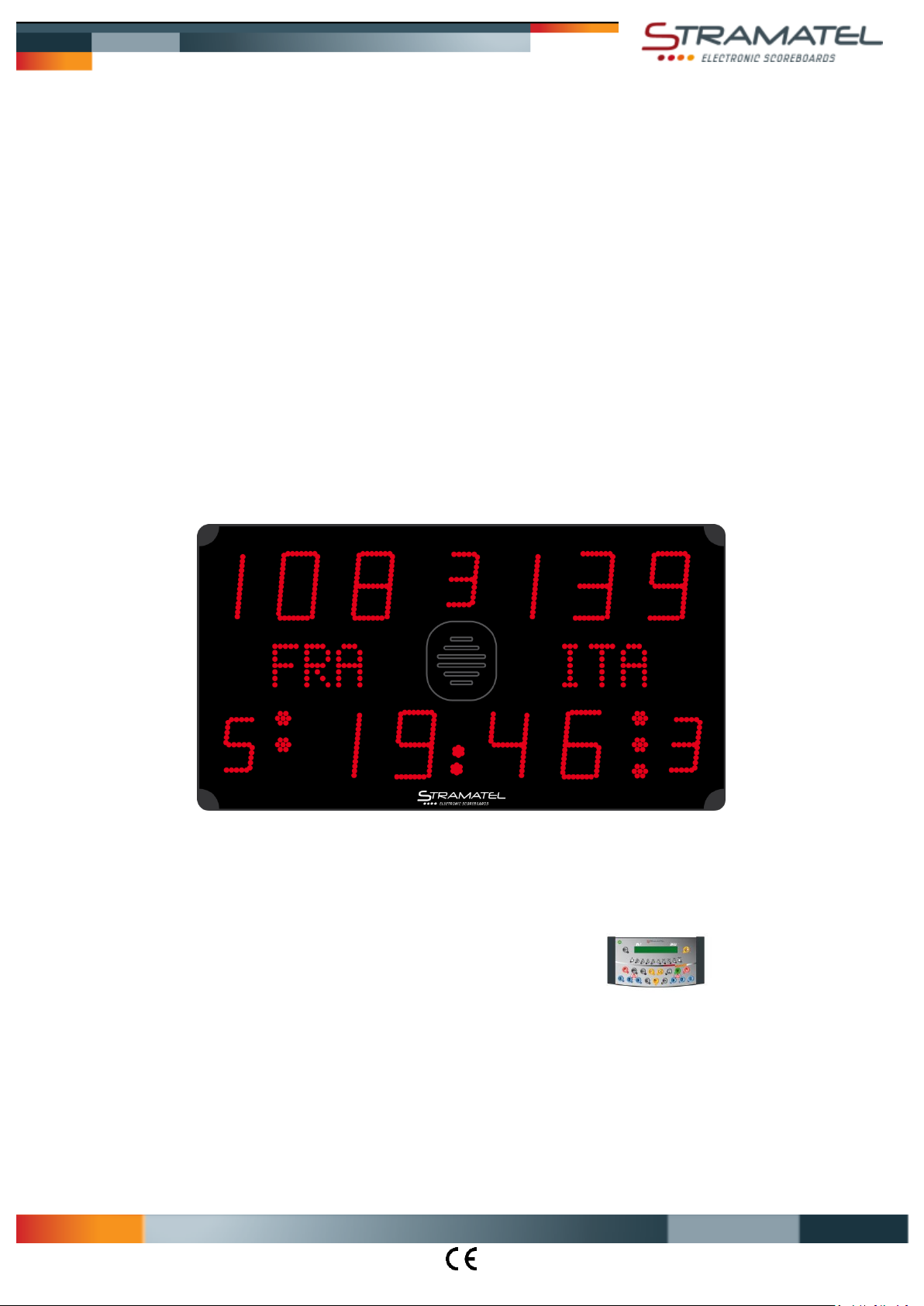
Multisport Serie Eco
TECHNISCHE DATEN - MONTAGEANLEITUNG
TYP 452 ME3100
Zeichnungen und Bilder sind unverbindlich
ZI de Bel Air 44850 LE CELLIER FRANKREICH [email protected] Tel. +33 (0)2 40 25 46 90
ID452ME3100R_A - Montageanleitung 452ME3100.docx Seite 1
Page 2
Multisport Serie Eco
Empfehlungen
Wir danken dafür dass Sie ein STRAMATEL Produkt gewählt haben und hoffen dass Sie damit vollkommen zufrieden sein werden.
Um eine einwandfreie Installation der Anlage durchzuführen, empfehlen wir Ihnen die nachfolgende Anleitung zu befolgen und das von
STRAMATEL gelieferte Material zu verwenden.
Falls Sie dennoch weitere Auskünfte benötigen sollten, notieren Sie bitte den Gerätetyp und dessen Seriennummer, die sich auf der
Klebeetikette der Unterseite des Bedienpultes befindet, und wenden Sie sich bitte an unseren technischen Dienst.
Jegliche Veränderung der gelieferten Teile kann eine Beschädigung des Gerätes verursachen und dadurch eine Annullierung der
Garantie zur Folge haben.
Anmerkung: die Installation muss von Fachpersonal durchgeführt werden und muss der Vorschrift IEC 364 sowie dem landesüblichen
Standard entsprechen.
Technische Daten
Die Anlage ist für den Innenbereich vorgesehen. Für die Reinigung der Anlage müssen Sie ein weiches, trockenes Tuch verwenden (nie
Wasser oder eine andere Flüssigkeit verwenden – Stromschlaggefahr).
Anzeigetafel
Gerät der Schutzklasse I – muss geerdet sein.
Abmessungen 1200 x 650 x 90 mm
Gewicht 14 kg
Stromversorgung 100-240V 50/60Hz 0,92-0,38A
Leistungsverbrauch 92VA
Lautstärke des Hupesignals (120dBa auf 1m): Der hohe Schalldruck kann zu Gehörbeschwerden führen. Die Zuschauer müssen in
einem angemessenen Abstand der Anzeigetafeln gehalten werden. Die Lautstärke des Hupesignals kann nicht eingestellt werden. Der
Ton kann jedoch gedämpft werden, indem das auf der Hupe angebrachte Gitter durch eine volle Abdeckung ersetzt wird (Abmessung
des Gitters 180x160mm).
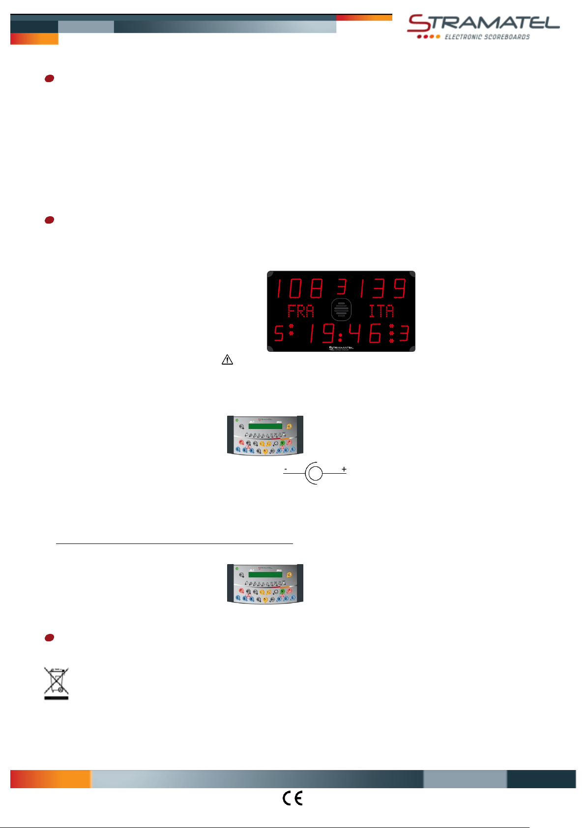
Bedienpult – Funkgesteuertes Modell
Abmessungen 340 x 175 x 60 mm
Gewicht 790 g
Sendefrequenz 869,7 - 870,0 MHz
Stromversorgung 100-240V 50/60Hz / 12Vdc 500mA
Akku NIMH 5x1,2V 1300mAh (16 Stunden Kapazität)
Nur die von STRAMATEL gelieferten Netzgeräte und Akkus benützen.
Aufladung des Bedienpultes: das Bedienpult ausschalten. Das Akkuladegerät an das Bedienpult und an das 230V Stromnetz anschließen
(eine Steckdose soll sich in der Nähe des Gerätes befinden und leicht zugänglich sein).
Nach Gebrauch muss das Bedienpult ständig auf Ladung bleiben.
Bedienpult – Kabelgesteuertes Modell
Abmessungen 340 x 175 x 60 mm
Gewicht 650 g
Stromversorgung: dieses Bedienpult wird durch die Anzeigetafel betrieben. Nur an STRAMATEL Geräte anschliessen.
Entsorgung von Altgeräten
Geräte mit dieser Kennzeichnung gehören nicht in den Restmüll und sind getrennt zu sammeln und zu entsorgen. Die Hersteller sorgen im
Rahmen der Produktverantwortung für eine umweltgerechte Behandlung und Verwertung der Altgeräte. Im Rahmen des
Elektro- und Elektronikgerätegesetzes (ElektroG) und zum Schutz unserer Umwelt ist eine kostenlose Rückgabe bei Ihrer
kommunalen Sammelstelle möglich.
ZI de Bel Air 44850 LE CELLIER FRANKREICH [email protected] Tel. +33 (0)2 40 25 46 90
ID452ME3100R_A - Montageanleitung 452ME3100.docx Seite 2
Page 3
1160
20
F F
F F
R
300
K
K
Z
610
20
20
20
Z
CC
CC
I I
M1
K
S
K
Multisport Serie Eco
Vorbereitung der Installation
Bei der Installation darf die Anzeigetafel auf keinen Fall geöffnet werden.
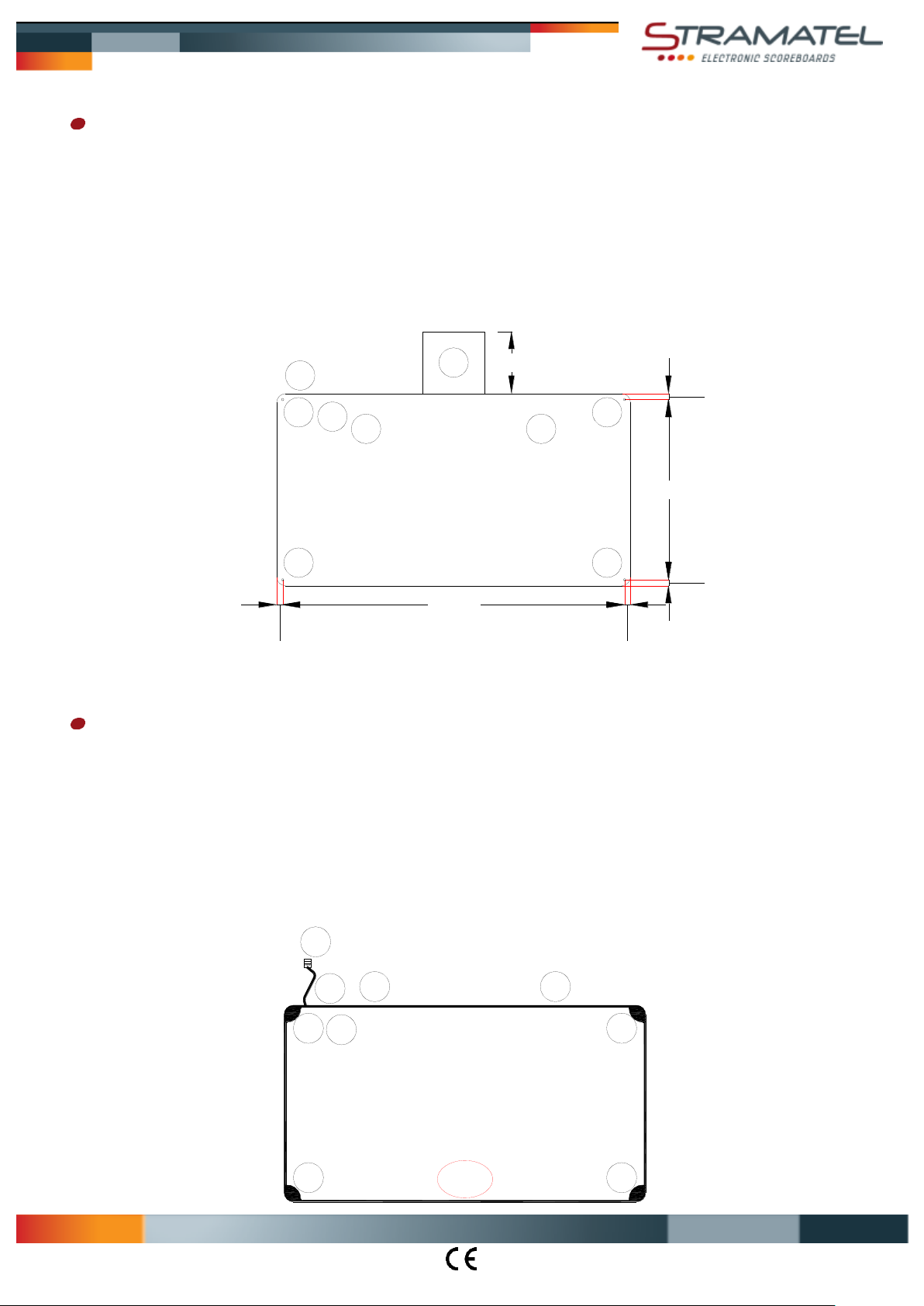
Die elektronischen Baugruppen sind auf einem ausziehbaren Träger (R) befestigt, der in der Anzeigetafel eingeschoben ist. Für die Wartung
der Anlage ist es notwendig einen Freiraum von ca. 30 cm zu lassen um diese Träger ausziehen zu können. Anmerkung: die Wartung muss
von Fachpersonal durchgeführt werden.
Das Netzkabel kann entweder durch das Gehäuseprofil herausgezogen werden oder auf der Hinterseite der Anzeigetafel (Durchgang K). Im
zweiten Fall muss es vor der Montage in der Anzeigetafel verkabelt werden. (siehe Kapitel "Elektrische Aufstellung" – "Netzkabel").
Markieren Sie die Befestigungspunkte (F) an der Wand oder an dem Gestell - dabei sollen die vorgegebenen Abmessungen beachtet
werden.
Setzen Sie eine Dübel oder Einschraubmutter ein, für Schrauben von Ø8mm.
Abmessungen in mm
(Z): Befestigungsloch, vorgesehen für die Wartung (Aufbau/Abbau der Frontseite).
Aufstellung der Anzeigetafel
Für eine erleichterte Installation der Anzeigetafeln, sind oben auf den Anzeigen Verankerungspunkte (I) vorhanden (Einsatzteile im
Aluprofil). Um die zu benutzen, setzen Sie M6x40 Ringschrauben ein.
Die genaue Reihenfolge der untenstehenden Arbeitsgänge muss beachtet werden.
Die Ecken (C) der Anzeige abschrauben und ausziehen.
Durchführung des Netzkabels: ein Kabel Pass (K) des Modules M1 wegnehmen und den Steckverbinder (S) durch den Durchgang
herausziehen.
Gegebenenfalls das Netzkabel an der Rückseite des Modules M1 verbinden (siehe Kapitel "Elektrische Aufstellung" – "Netzkabel").
Positionieren Sie das Modul M1 und befestigen Sie es an der Wand oder auf einem Gestell mit Ø8mm Schrauben.
ZI de Bel Air 44850 LE CELLIER FRANKREICH [email protected] Tel. +33 (0)2 40 25 46 90
ID452ME3100R_A - Montageanleitung 452ME3100.docx Seite 3
Page 4
S
K
K
P
100-240V
50/60Hz
SC24 SC24
1
2
3
4
YBJ35
T
Q
YBJ35
2
4
1
3
SC24
T
A
Multisport Serie Eco
Elektrische Aufstellung - Funkgesteuertes Modell
Anmerkung: die Anlage darf erst am Ende der Installation an das Stromnetz angeschlossen werden.
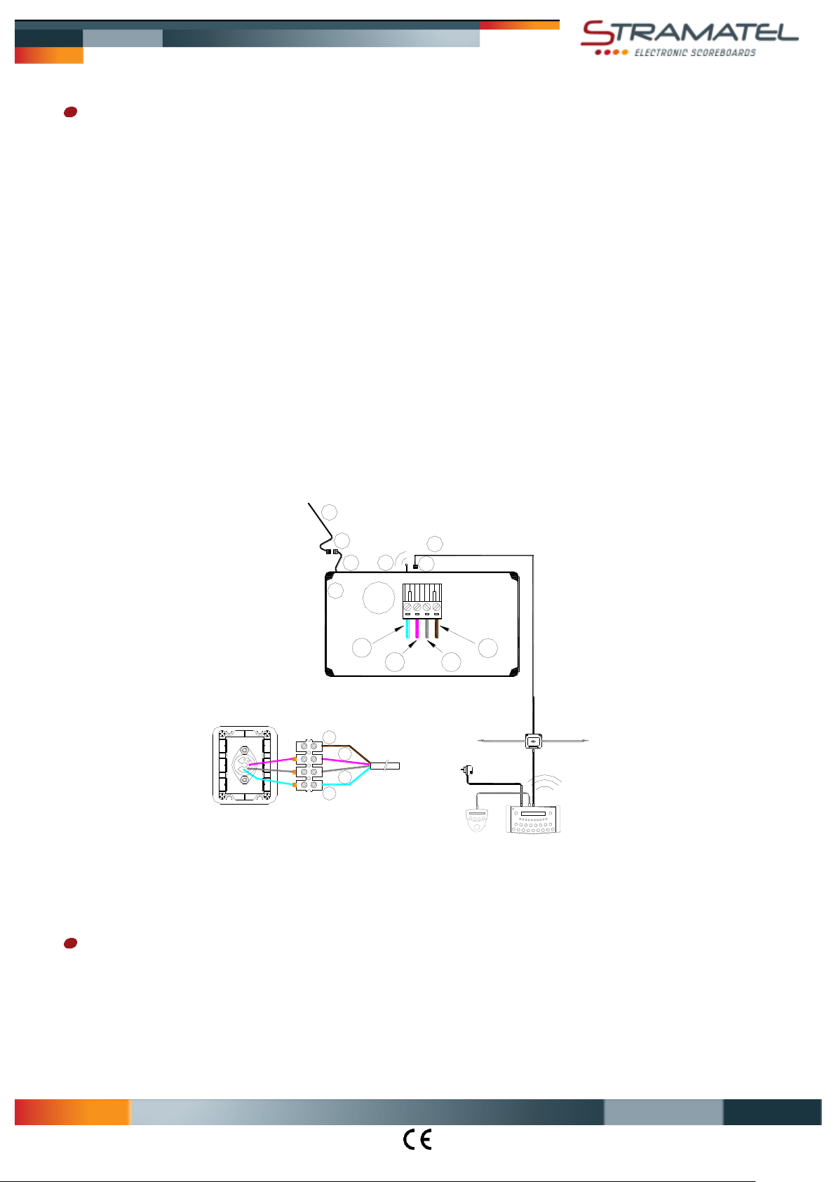
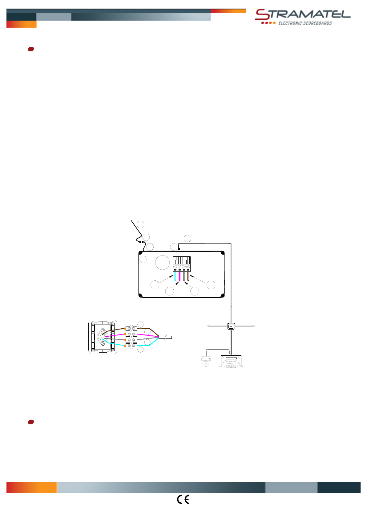
Für die Option zusätzliches Kabelset: Steuerkabel und Anschlußdose
Als Anschlußkabel wird ein 4-adriges Telefonkabel 6/10 verwendet.
Die Anschlußdose YBJ35 in der Nähe des Anschreibertisches befestigen.
Schließen Sie das Steuerkabel (Q) an den Steckverbinder (T) der Anzeigetafel an. Beachten Sie die Farben wie angezeigt (ANMERKUNG
– RS485: Rx+ und Rx- müssen unbedingt auf ein verseiltes Paar verbunden werden).
Legen Sie das Steuerkabel an. Beachten Sie dabei, dass es nicht mit dem Stromleitungskabel der Sporthalle eingezogen wird.
Schließen Sie das Steuerkabel an die Anschlußdose YBJ35 an; beachten Sie dabei die angegebenen Kabelfarben. Wenn mehrere
Anzeigetafeln zusammen verbunden sind, müssen die Kabeln parallel an die Anschlußdose gesteckt werden.
Netzkabel (P)
Anmerkung: nur das gelieferte Netzkabel verwenden. Dieses Kabel ist mit einem verdrahtetem Steckverbinder versehen und darf nicht
verändert werden.
Zwei Öffnungen (K) sind für die Durchführung des Netzkabels vorhanden: eine im Gehäuseprofil und eine andere auf der Rückseite der
Anzeigetafel.
Entfernen Sie den Kabel Pass, ziehen Sie den Steckverbinder (S) raus und verbinden Sie das Netzkabel.
Legen Sie den Steckverbinder (S) in der Anzeigetafel zurück und legen Sie den Kabel Pass wieder darüber.
Setzen Sie das Netzkabel (P) ein und stecken Sie es an das Stromnetz 100-240V an, mittels einer bipolaren Sicherung, geschützt bei 4A
(nicht mitgeliefert). Die Sicherung muss leicht zugänglich sein.
Steuerkabel (Q) : (1) = GND = blaue Ader / (2) = Rx+ = weiße Ader / (3) = Rx- = graue Ader / (4) = +24V = durchsichtige Ader
Ende der Installation
Die Kunststoffecken wieder anschrauben.
Die Anzeigetafel mit Hilfe der Bedienungsanleitung testen.
ZI de Bel Air 44850 LE CELLIER FRANKREICH [email protected] Tel. +33 (0)2 40 25 46 90
ID452ME3100R_A - Montageanleitung 452ME3100.docx Seite 4
Page 5
S
YBJ30
K
K
P
100-240V
50/60Hz
SC24 SC24
1
2 3
4
YBJ30
T
2
4
1
3
T
Q
SC24
Multisport Serie Eco
Elektrische Aufstellung – kabelgesteuertes Modell
Anmerkung: die Anlage darf erst am Ende der Installation an das Stromnetz angeschlossen werden.
Steuerkabel und Anschlußdose
Als Anschlußkabel wird ein 4-adriges Telefonkabel 6/10 verwendet.
Die Anschlußdose YBJ30 in der Nähe des Anschreibertisches befestigen.
Schließen Sie das Steuerkabel (Q) an den Steckverbinder (T) der Anzeigetafel an. Beachten Sie die Farben wie angezeigt (ANMERKUNG
– RS485: Rx+ und Rx- müssen unbedingt auf ein verseiltes Paar verbunden werden).
Legen Sie das Steuerkabel an. Beachten Sie dabei, dass es nicht mit dem Stromleitungskabel der Sporthalle eingezogen wird.
Schließen Sie das Steuerkabel an die Anschlußdose YBJ30 an; beachten Sie dabei die angegebenen Kabelfarben. Wenn mehrere
Anzeigetafeln zusammen verbunden sind, müssen die Kabeln parallel an die Anschlußdose gesteckt werden.
Netzkabel (P)
Anmerkung: nur das gelieferte Netzkabel verwenden. Dieses Kabel ist mit einem verdrahtetem Steckverbinder versehen und darf nicht
verändert werden.
Zwei Öffnungen (K) sind für die Durchführung des Netzkabels vorhanden: eine im Gehäuseprofil und eine andere auf der Rückseite der
Anzeigetafel.
Entfernen Sie den Kabel Pass, ziehen Sie den Steckverbinder (S) raus und verbinden Sie das Netzkabel.
Legen Sie den Steckverbinder (S) in der Anzeigetafel zurück und legen Sie den Kabel Pass wieder darüber.
Setzen Sie das Netzkabel (P) ein und stecken Sie es an das Stromnetz 100-240V an, mittels einer bipolaren Sicherung, geschützt bei 4A
(nicht mitgeliefert). Die Sicherung muss leicht zugänglich sein.
Steuerkabel (Q) : (1) = GND = blaue Ader / (2) = Rx+ = weiße Ader / (3) = Rx- = graue Ader / (4) = +24V = durchsichtige Ader
Ende der Installation
Die Kunststoffecken wieder anschrauben.
Die Anzeigetafel mit Hilfe der Bedienungsanleitung testen.
ZI de Bel Air 44850 LE CELLIER FRANKREICH [email protected] Tel. +33 (0)2 40 25 46 90
ID452ME3100R_A - Montageanleitung 452ME3100.docx Seite 5
Page 6
Multisport Eco Range
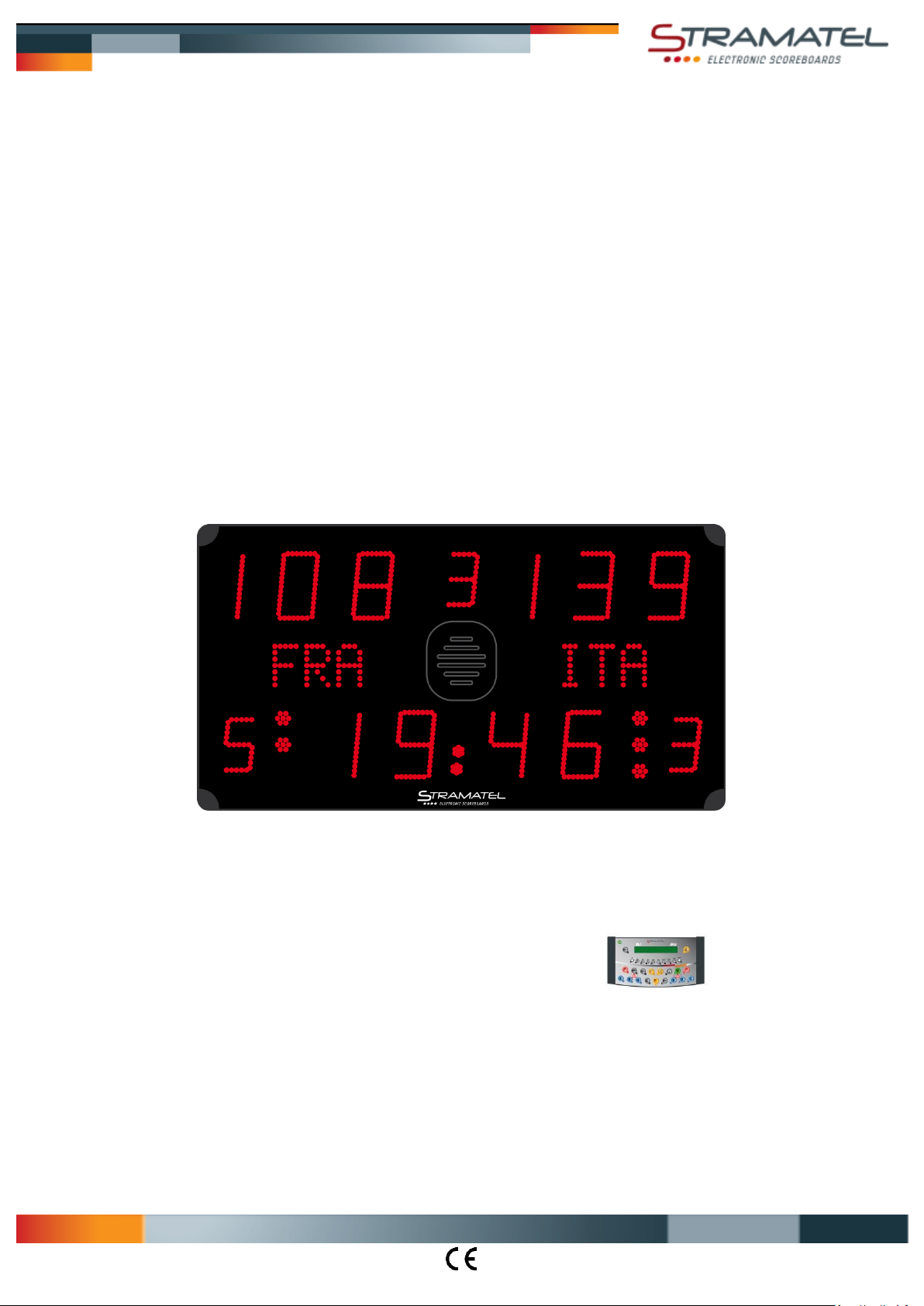
TECHNICAL DATA - INSTALLATION INSTRUCTIONS
Model 452 ME 3100
Non-binding pictures
ZI de Bel Air 44850 LE CELLIER FRANCE [email protected] Tél. +33 (0)2 40 25 46 90
IA452ME3100R_A - Installation 452ME3100.docx Page 1
Page 7
Multisport Eco Range
Recommendations
Thank you for choosing a STRAMATEL scoreboard!
We hope that you will be fully satisfied with our product. For any information, please do not hesitate to contact us.
In order to install the scoreboard set correctly, we recommend that the instructions indicated are followed correctly, and that the
material supplied by STRAMATEL is used correctly without any alteration.
However, if extra information is required, please contact Stramatel technical service with the model reference and serial number (on
the sticker under the control console).
Any alteration made to the equipment delivered may deteriorate it and result in the cancelling of the warranty.
Caution: Installation must be performed by qualified staff and must comply with IEC 364 and national wiring regulations.
Technical data
Equipment for indoor use only.
Use a soft dry cloth to clean the equipment (Never use water or other liquids – risk of electric shock).
Scoreboard
Class I equipment – Must be connected to earth.
Dimensions 1200 x 650 x 90 mm
Weight 14 kg
Power supply 100-240V 50/60Hz 0,92-0,38A
Power consumed 92VA
Horn loudness (120dBa at 1m): the high sound pressure can deteriorate hearing. Therefore, the spectators should be kept at a
reasonable distance from the scoreboard. The horn is not equipped with the possibility to adjust the loudness of its sound. However, it
is possible to dampen down the sound by replacing the grill in front of the horn by a full plate of the same dimension (180x160mm).
Control console – Radio controlled model
Dimensions 340 x 175 x 60 mm
Weight 790 g
Transmission frequency 869,7 - 870,0 MHz
Power supply 100-240V 50/60Hz / 12Vdc 500mA
Internal batteries NIMH 5x1,2V 1300mAh (16 hours autonomy)
Use only power supply and batteries supplied by STRAMATEL.
Control console recharge: turn off the control console. Plug the power supply into the back of the control console, then plug it into an
appropriate mains outlet (the socket should be as close as possible to the control console and must be easily accessible).
Leave the control console under constant recharge when not in use.
Control console – Cable transmission model
Dimensions 340 x 175 x 60 mm
Weight 650 g
Power supply: the control console is powered by the scoreboard. It should only be connected to the STRAMATEL system supplied.
Environment and recycling
Please help us to protect the environment by disposing of the packaging in accordance with the national regulations for waste processing.
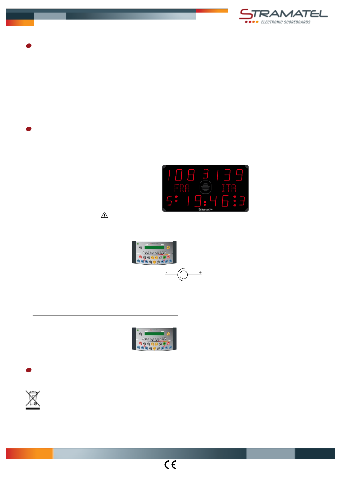
Recycling of obsolete appliances: appliances with this label must not be disposed off with the general waste. They must be
collected separately and disposed off according to local regulations.
ZI de Bel Air 44850 LE CELLIER FRANCE [email protected] Tél. +33 (0)2 40 25 46 90
IA452ME3100R_A - Installation 452ME3100.docx Page 2
Page 8
1160
20
F F
F F
R
300
K
K
Z
610
20
20
20
Z
CC
CC
I I
M1
K
S
K
Multisport Eco Range
Before installation
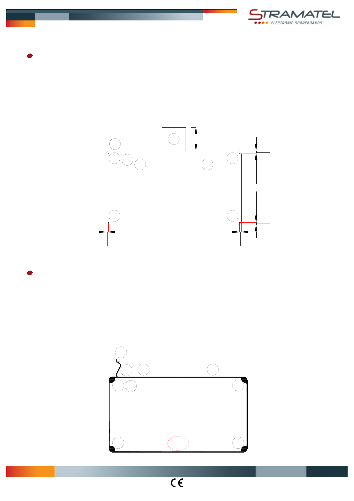
In no circumstances does installation require the scoreboard casing to be opened.
The electronic elements controlling the luminous display are mounted on extractable racks (R). In order to be able to carry out any
maintenance, a clear space of at least 30 cm is necessary for the extraction of the racks. Attention: installation must be performed by
qualified staff.
The mains cable can be taken out through the profile or at the back of the scoreboard (points K). In this last case, the mains cable must be
connected in the scoreboard before being fixed (see chapter "Electrical installation" – "Mains cable").
Draw the position of the mounting points (F) onto the wall or onto the support frame following the measures of the diagram.
Put plugs or inserts for Ø 8 mm screws.
Dimensions in mm
(Z): Holes for mounting or disassembling the front face in some maintenance cases.
Scoreboard installation
In order to make installation easier, anchor points (I) are available on the top side of the scoreboard (insert holes in aluminium frame).
Screw-rings, type M6x40 (not supplied) can be screwed into place in each hole.
Please strictly follow the below instructions.
Unscrew and slide out the plastic corner shields (C) of the scoreboard.
Mains cable port: remove one of the grommets (K) of the module M1 and take the connector (S) out through the cable port.
If needed, connect the mains cable at the back of the module M1 (see chapter "Electrical installation" – "Mains cable").
Put the module M1 into place on the wall or on the support frame and screw in Ø 8 mm screws.
ZI de Bel Air 44850 LE CELLIER FRANCE [email protected] Tél. +33 (0)2 40 25 46 90
IA452ME3100R_A - Installation 452ME3100.docx Page 3
Page 9
S
K
K
P
100-240V
50/60Hz
SC24 SC24
1
2
3
4
YBJ35
T
Q
YBJ35
2
4
1
3
SC24
T
A
Multisport Eco Range
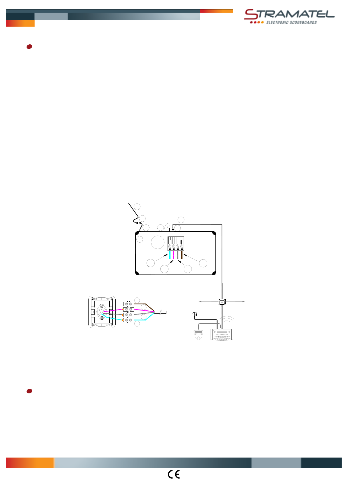
Electrical installation - Radio controlled model
Caution: the scoreboard must not be connected to mains before installation has been fully completed.
In case a cable set needs to be installed: control cable and wall junction box
The transmission cable supplied is a telephone cable: type 2 pairs 6/10
Mount the wall junction box YBJ35 onto the wall close to the scoring table.
Connect the control cable (Q) on the connector (T) of the scoreboard making sure that the colour code is followed (Please note –
RS485: Rx+ and Rx- must be connected on a twisted pair).
Fix the control cable into place making sure that it does not run along side the 100-240V mains cables.
Connect the end wires into the junction box YBJ35, making sure that the colour code is followed. If several units are connected
together, their cables must be wired in parallel in the wall junction box.
Mains cable (P)
Caution: only use the power cable provided. This cable is equipped with pre-wired plug; the wiring should not be modified.
Two cable ports (K) are available for the mains cable: one in the profile of the scoreboard another one at the back.
Remove the grommet of the scoreboard, take the connector (S) out and connect the mains cable.
Put the connector (S) inside the scoreboard and put the grommet back into place.
Run and fix the mains cable (P) and connect it to 100-240V via a bipolar 4A circuit breaker (not supplied). Bipolar circuit breaker must
be easy to reach.
Control cable (Q): (1) = GND = blue wire / (2) = Rx+ = white wire / (3) = Rx- = grey wire / (4) = +24V = transparent wire
End of the installation
ths
.
Slide back and screw in each of the corner plastic shields.
Try out the scoreboard operating functions (see operating functions).
ZI de Bel Air 44850 LE CELLIER FRANCE [email protected] Tél. +33 (0)2 40 25 46 90
IA452ME3100R_A - Installation 452ME3100.docx Page 4
Page 10
S
YBJ30
K
K
P
100-240V
50/60Hz
SC24 SC24
1
2 3
4
YBJ30
T
2
4
1
3
T
Q
SC24
Multisport Eco Range
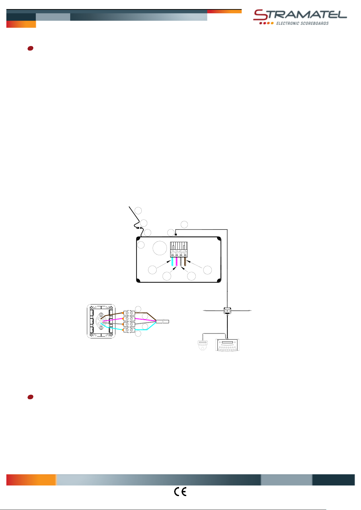
Electrical installation - Cable transmission model
Caution: the scoreboard must not be connected to mains before installation has been fully completed.
Control cable and wall junction box
The transmission cable supplied is a telephone cable: type 2 pairs 6/10
Mount the wall junction box YBJ30 onto the wall close to the scoring table.
Connect the control cable (Q) on the connector (T) of the scoreboard making sure that the colour code is followed (Please note –
RS485: Rx+ and Rx- must be connected on a twisted pair).
Fix the control cable into place making sure that it does not run along side the 100-240V mains cables.
Connect the end wires into the junction box YBJ30, making sure that the colour code is followed. If several units are connected
together, their cables must be wired in parallel in the wall junction box.
Mains cable (P)
Caution: only use the power cable provided. This cable is equipped with pre-wired plug; the wiring should not be modified.
Two cable ports (K) are available for the mains cable: one in the profile of the scoreboard another one at the back.
Remove the grommet of the scoreboard, take the connector (S) out and connect the mains cable.
Put the connector (S) inside the scoreboard and put the grommet back into place.
Run and fix the mains cable (P) and connect it to 100-240V via a bipolar 4A circuit breaker (not supplied). Bipolar circuit breaker must
be easy to reach.
Control cable (Q): (1) = GND = blue wire / (2) = Rx+ = white wire / (3) = Rx- = grey wire / (4) = +24V = transparent wire
End of the installation
Slide back and screw in each of the corner plastic shields.
Try out the scoreboard operating functions (see operating functions).
ths
.
ZI de Bel Air 44850 LE CELLIER FRANCE [email protected] Tél. +33 (0)2 40 25 46 90
IA452ME3100R_A - Installation 452ME3100.docx Page 5
 Loading...