

Page 1

Introduction
Straight
C
o
Multi-functional access point
r
e
GWP-106VE
IEEE 802.11b/g
54Mbps
English version
User Manual
1
Page 2

Introduction
Contents
Chapter 1 Introduction............................................................................................................................ 3
1.1 Content of the package................................................................................................................. 3
1.2 Functions of the unit...................................................................................................................... 3
1.3 Specification.................................................................................................................................. 3
1.4 Description and installation of the unit.......................................................................................... 4
1.4.1 External part - ODU ........................................................................................................ 4
1.4.2 Internal part – IDU........................................................................................................... 4
Chapter 2 Configuration of the unit.......................................................................................................7
2.1 Preparation for configuration ........................................................................................................ 7
2.1.1 Setting your PC............................................................................................................... 7
2.2 Statistics ........................................................................................................................... 8
2.2.1 Status of the unit............................................................................................................. 8
2.2.2 Available networks ................................................................................................ 8
2.2.3 Data .......................................................................................................................... 8
2.2.4 Wireless connection ................................................................................................. 8
2.2.5 DHCP Clients .......................................................................................................... 8
2.2.6 WDS Connection ....................................................................................................8
2.2.7 Routing table ............................................................................................................ 8
2.2.8 ARP Table .............................................................................................................. 8
2.3 Setting the operating mode ....................................................................................................... 9
2.4 Setting of the wireless part ........................................................................................................... 9
2.4.1 Setting the basic parameters of the wireless connection: ........................................... 10
2.4.2 Advanced setting of radio transmission ...................................................................... 11
2.4.3 Security ................................................................................................................. 12
2.4.4 Filtering of MAC addresses .................................................................................... 14
2.5 IP setting ..................................................................................................................................... 14
2.5.1 LAN port TCP/IP setting ............................................................................................ 14
2.5.2 WAN port TCP/IP setting .............................................................................................. 15
2.5.3 Gateway and Routing ............................................................................................ 15
2.6 Network and Firewall .................................................................................................................. 16
2.6.1 IP/MAC Address Blocking, Port Blocking ................................................................... 16
2.6.2 Port forwarding ...................................................................................................... 16
2.6.3 Setting DMZ (Demilitarized Zone) ................................................................................ 16
2.7 Services ...................................................................................................................................... 16
2.7.1 Rate limit ............................................................................................................... 16
2.7.2 DDNS setting ........................................................................................................ 16
2.7.3 Tile server ............................................................................................................. 17
2.7.4 Watchdog/Restart ................................................................................................. 17
2.7.5 Network test ......................................................................................................... 17
Chapter 3 Administration ..................................................................................................................... 18
3.1.1 Changing password ............................................................................................... 18
3.1.2 Save/Restore configuration .................................................................................... 18
3.1.3 Update ................................................................................................................. 18
3.1.4 Web interface ........................................................................................................ 18
3.2 Restart ........................................................................................................................................ 18
Chapter 4 Troubleshooting .................................................................................................................... 1
English version
2
Page 3

Introduction
Chapter 1 Introduction
Thank you very much for purchasing the GWP-207VE wireless client unit. This is a unit for building
the network according to the 802.11b or 802.11g standard. Wireless units consist of access points (the unit
in the “Access Point” regime) and client devices (the unit in the infrastructure regime). For interconnection of
further computers without an access point it is possible to use an AD-HOC setting, for building a Point-Point
connection, it is possible to use WDS/Bridge regime.
This unit supports WEP, WPA, ESSID security systems and a MAC address filter to ensure security
of the wireless network. Due to these security standards it is possible to avoid any unauthorized access to
your wireless network.
This unit is equipped with a 14 dB gain aerial integrated panel. Using a www interface, this equipment
enables the control of the overall emitted output, i.e. the output which includes the gain of the aerial.
This unit can be easily controlled by any web browser which is localised into several languages.
Contact your supplier to receive the current list of language modifications for the user interface or you can
find it on the web pages of the producer at
The firmware (the control program of the unit) is developed with the emphasis placed on the use in
large wireless networks. The cover of the unit is designed for use outside of buildings with sufficient
protection against drip and other atmospheric influences. For easy setting it is possible to connect the GWPHDF direction finder to the unit whose description and the use is contained in this Manual.
Note: This manual is written for firmware version 1.0.6. Recent firmware may contain functions not contained
in this version of the manual.
You can find pictures in the colour appendix in the end of the manual. The number of the picture
www.straightcore.net.
related to the respective chapter is always located beside the symbol
1.1 Content of the package
The package contains the following items:
y One Quick Installation Manual
y One Access Point
y One Power Adapter
y One PSW-105 Switch with POE system (optional)
1.2 Functions of the unit
y Compatible with specification IEEE 802.11b/g (DSSS) 2.4GHz.
y Waterproof construction with integrated 14 dB aerial
y Power-over-Ethernet (PoE) system
y High transmission rate up to 54 Mbps.
y Simple integration to current LAN networks.
y Automatic access rate reduction in an interfering environment.
y 64/128-bit WEP and WPA Encryption Function for wireless transmission security.
y Integrated DHCP server for automatic IP address assigning.
y Web based control.
1.3 Specification
y Standards: IEEE 802.11b/g (Wireless section), IEEE 802.3 (LAN section)
y Transmission Rates: 54/48/36/24/18/12/11/9/6/5.5/2/1Mbit/sec with automatic reduction in an
interfering environment
y Security: 64/128-bit WEP and WPA transmission encryption
y Frequency range: 2.400~2.4835GHz (ISM band)
English version
3
Page 4

Introduction
y Modulation:
802.11b - CCK@11/5.5Mbps, DQPSK@2Mbps a DBPSK@1Mbps
802.11g – BPSK,SPSK,16QAM,64QAM
y Wireless Technology: DSSS pro 802.11b, OFDM pro 802.11g
y Aerial: External disconnecting 2dB (connector RP-SMA)
y Network connector:
ODU-10/100Mbps RJ-45 x 2, GWP-HDF port (USB connector) x1
IDU – 5xRJ45 (PoE standard on port 1, optional 2,3,4)
y Voltage: 12V DC
y High-frequency output: max 19.8 dBmW
y LED diodes:
ODU - Supply, Link (on connectors RJ-45)
IDU - Supply, 4x LAN Line/Activity/PoE system, 1x LAN Line/Activity
y Temperature range:
Operation: -35°C~65°C
Storage: -35°C~70°C
y Humidity: 10-90% (non-condensing)
y Certification: FCC, CE
1.4 Description and installation of the unit
1.4.1 External part - ODU
Part of the unit is designated for locating on an installation mast. In the front part it contains an integrated 12
dB aerial.
1.4.1.1 Ethernet/POE port
In the bottom part of the external unit you can find the waterproof part covered by a plastic cover. In this
part there is port for an RJ-45 connector and the Reset button. For the connection of the unit to an internal
part it is always necessary to use fully equipped STP shielded cable of the category 5,5e or 6. In the case of
use of unshielded cable, the unit or the connected computer can be damaged due to the influence of static
discharge. After connection of the connector into the port ensure the correct installation of the waterproof
cover and its fixation with the attached bolt.
Mount the unit on the mast by means of the holder and fork which is a part of the accessories. If you
attach the unit to the mast so that the LED diodes on the front side are on the top, the unit will be in vertical
polarization. For attaching in horizontal polarization turn the holder by 90 degrees so that the Ethernet cable
is protected by the offset in the cover against drip. Then, connect the plastic form with the centre bolt and
after attaching the whole unit to the mast, tighten the bolt so that the declination of the unit best corresponds
to the direction of the location of the transmission point to which GWP-106VE will be connected.
1.4.1.2 Reset button
The unit is equipped with a button for its resetting or for switching to the factory setting. This button is
located on the right side of the RJ-45 connector. Use a ballpoint pen or other suitable tool to press it. Use
as follows:
• Press the button for a short period less than 4 seconds to restart the access point. In this case
the configuration parameters will remain kept.
• In the case of the loss of password or IP address it is possible to switch the contact for a period
longer than 4 seconds. In this case the factory setting will be reset and there will be a restart of
the access point to the initial address 192.168.1.1 and it will not be protected by a user name
and password.
1.4.2 Internal part – IDU
The internal part of the unit is delivered in two variants which correspond to the following descriptions:
English version
4
Page 5

Introduction
1.4.2.1 Standard Power Injector
In the standard variant the unit is delivered with a standard injector without the integrated switch. The
connection is easy. Connect the Ethernet cable from your PC or the switch into the port marked LAN. The
POE port is used for the connection of the cable leading to the ODU unit. Connect the delivered network
adapter into the port of the described DC – now the installation is complete. Attention, in the case of
incorrect connection of cables into individual ports there can be serious damage to your switch or
computer. Therefore, we recommend to use for this connection a Cat.3 4 or 5 cable with only 1,2,3 and 6
contacts connected. In this case there is no risk of damage because the POE system uses transfer on
contacts 4/5 and 7/8 as schematically displayed on the upper side of the POE injector.
It is possible to use side clamps and small screws for mounting of the injector on the wall which is
not part of the delivery. The span of the assembly holes is 68 mm.
1.4.2.2 PSW-105/205
The optional accessory to the GWP-106VE unit is the PSW-105/205 projector with an integrated 4pole switch. This variant is equipped with an LED diode for checking the function. The description of the
status and the function of individual LED diodes are in the following table:
LED Colour Status Description
Power Orange
Green
1-4/POE
5 Green
Orange
Red
ON Supply to the unit is connected
OFF No supply
OFF Line disconnected, POE inactive
Red Line disconnected, POE active for respective port
Orange ON Line connected, POE active for respective port
Orange, flashes Line connected, POE active, data transfer
Green ON Line connected, POE inactive
Green flashes Line connected, POE inactive, data transfer
ON
Flashes The line is transmitting or receiving data.
OFF Line disconnected
Line connected.
1.4.2.2.1. POE System
The IDU PSW-105 is equipped with a POE system (Power-over-ethernet). In the standard configuration the
PoE is active only on port No.1 which is used for the supply of the unit. In special cases, by interconnection
of the J1 switch on the board of the switch it is possible to also switch the ON supply for ports 2-4 and to
supply up to 4 external units with one PSW-105 switch (in this case , it is necessary to replace the delivered
source with the 12V/2A source). Further options for the use of this regime is, for example, the installation of
one switch for PC with an active POE port 1 and the supply of a distant switch in the regime of 4 POE ports
by means of the POE system. It is possible to use the remaining 3 ports for connection of 3 external GWP207VE units.
For fast specification of the configuration of PSW-105, connect only the supply voltage. The ports on which
the POE system is active are indicated by a permanently lit red LED diode.
1.4.2.2.2. Supply of IDU/Connection of further units
The DC-12V connector serves for the connection of the supply voltage. The standard delivery includes the
12V/500mA source which is sufficient for the operation of the switch and one unit on the cable with a length
of 15 m. In the case of operation with a longer cable, it is possible to use for the supply a stabilized
maximum 18V source. With the increase of the input voltage it is possible to ensure stable operation up to
70 m of the Ethernet line. In the case of connection of further units to one PSW-105, it is necessary, on the
contrary, to increase the input current. For each connected unit it is necessary to consider the current as
400mA and for each remotely supplied switch the current as 100mA.
English version
5
Page 6

Introduction
1.4.2.2.3. Ethernet ports 1/5
The connector is for the connection of the equipment into a standard LAN computer network with a Cat.5,5E
or Cat.6 cable. Attention, connect only StraightCore external units to ports with an active POE system. The
connection of any other equipment may damage the switch and the connected equipment.
.
English version
6
Page 7

Configuration of the wireless access point LAN
Chapter 2 Configuration of the unit
2.1 Preparation for configuration
This unit provides easy control through a www browser. Access the configuration using the following steps.
2.1.1 Setting your PC
Make sure your computer is configured to the same IP address range as the wireless unit. The factory
setting of TCP/IP is as follows:
Default IP Address: 192.168.1.1
Network mask: 255.255.255.0
Configuration of TCP/IP parameters of your PC.
1a) Windows 95/98/Me
1. Click the Start button and select the Setting tab, then the Control Panel window will appear.
2. Double click on the Network connections icon.
3. Check the displayed items. If the TCP/IP protocol is not installed, press the Add button If the
TCP/IP has already been installed, follow step 6.
4. In the Network component type dialog select Protocol and click on Add.
5. In the Network protocol type window select TCP/IP and click on Add. To complete the
installation you may need the operation system installation disk.
6. After installation of the TCP/IP protocol, return to the network component list, select TCP/IP
protocol and press the Properties button.
7. Check all tabs and complete with the following parameters:
• Bindings: Check Client for Microsoft network and File and Printer sharing.
• Gateway: Leave all fields empty.
• DNS Configuration: Select Disable DNS.
• WINS: Select Disable WINS.
• IP Address: Select Enter IP Address. Enter the IP Address and the mask as in the
following example:
9 IP Address: 192.168.1.3 (any IP address from 192.168.1.2~192.168.1.254 range
is possible, do not enter 192.168.1.1)
9 Network mask: 255.255.255.0
8. Restart the computer. After rebooting, your computer will use the IP address you entered.
1b) Windows XP
1: Press the Start button and select Control panels then press the Network connection. The Network
connections windows will appear.
2: Double click on the Local network connection icon.
3: The window will appear. Select TCP/IP from the list and press the Properties button.
4: Fill the Internet Protocol (TCP/IP) – properties dialog box according to the following example.
IP address: 192.168.1.2
Sub-network mask: 255.255.255.0
5: Press OK. Now your PC is configured to access the unit.
Enter the IP address of the unit 192.168.1.1 into your www browser to access the configuration. In
the default configuration the unit is protected by a password and user name. Now you can configure the
GWP-106VE unit for connection to the access point.
English version
7
Page 8
Configuration of the wireless access point LAN
2.2 Statistics 1
Pic.1 in the Appendix shows the starting page for access of the unit control. Access the configuration
parameters using the pair of menus. In the left upper part under the logo of the producer there is a primary
menu with the main menu items. Above the screen there is a dynamic menu. Its content is changed
depending on the actual selected item of the main menu.
2.2.1 Status of the unit
This opening screen contains information about the current setting of the unit, the time of running
from the last restart, the version of the HW and SW unit, the selected network key, the operating mode of the
unit, etc. The important information which you will need for setting your wireless network is “WiFi MAC
address – BSSID” value. This is the network address of the wireless part of the unit which the unit uses to
login into your wireless network. If you use the unit in the “Station – Infrastructure” mode, and your access
point to connect to perform MAC address filtering, you must ensure your unit MAC address passes through
the filter.
2.2.2 Available networks 2
If the unit is in some of operating modes of the “Station” type, after pressing the “Restore“ button on
the “Available networks” page then all available wireless networks will be searched. The table provides
information about the SSID network, the MAC address of the unit found, the operating channel, type of
network and the strength of the signal. After selection of the respective network in the right column it is
possible to set the parameters of the respective network with the “Connect” button. If the network uses any
encrypting standards, it is necessary to set these parameters manually.
2.2.3 Data 3
On the “Data” page it is possible to find the statistics of the received and sent packets for the individual
interfaces of the unit since its last restart.
2.2.4 Wireless connection 4
The “Wireless connection” page provides you in Access Point mode, information on the currently
connected Client stations, the amount of transmitted data and the signal strength. Click on the "advanced"
button to enhance the table with other detailed communication parameters with individual stations.
2.2.5 DHCP Clients 5
When the DHCP server is enabled on the unit, the table on the “DHCP Clients” page will report the
currently assigned IP addresses for each client.
2.2.6 WDS Connection 6
If the unit is configured as a part of a WDS system, the table on this page shows the parameters of
the individual stations of the WDS system.
2.2.7 Routing table 7
On the “Routing table” page you can find the actual rules for routing of the unit. It is possible to edit
these rules in the static routes menu.
2.2.8 ARP Table 8
The “ARP Table” page provides information about the MAC addresses of the connected devices
both on the wireless and the metallic side of the unit.
English version
8
Page 9
Configuration of the wireless access point LAN
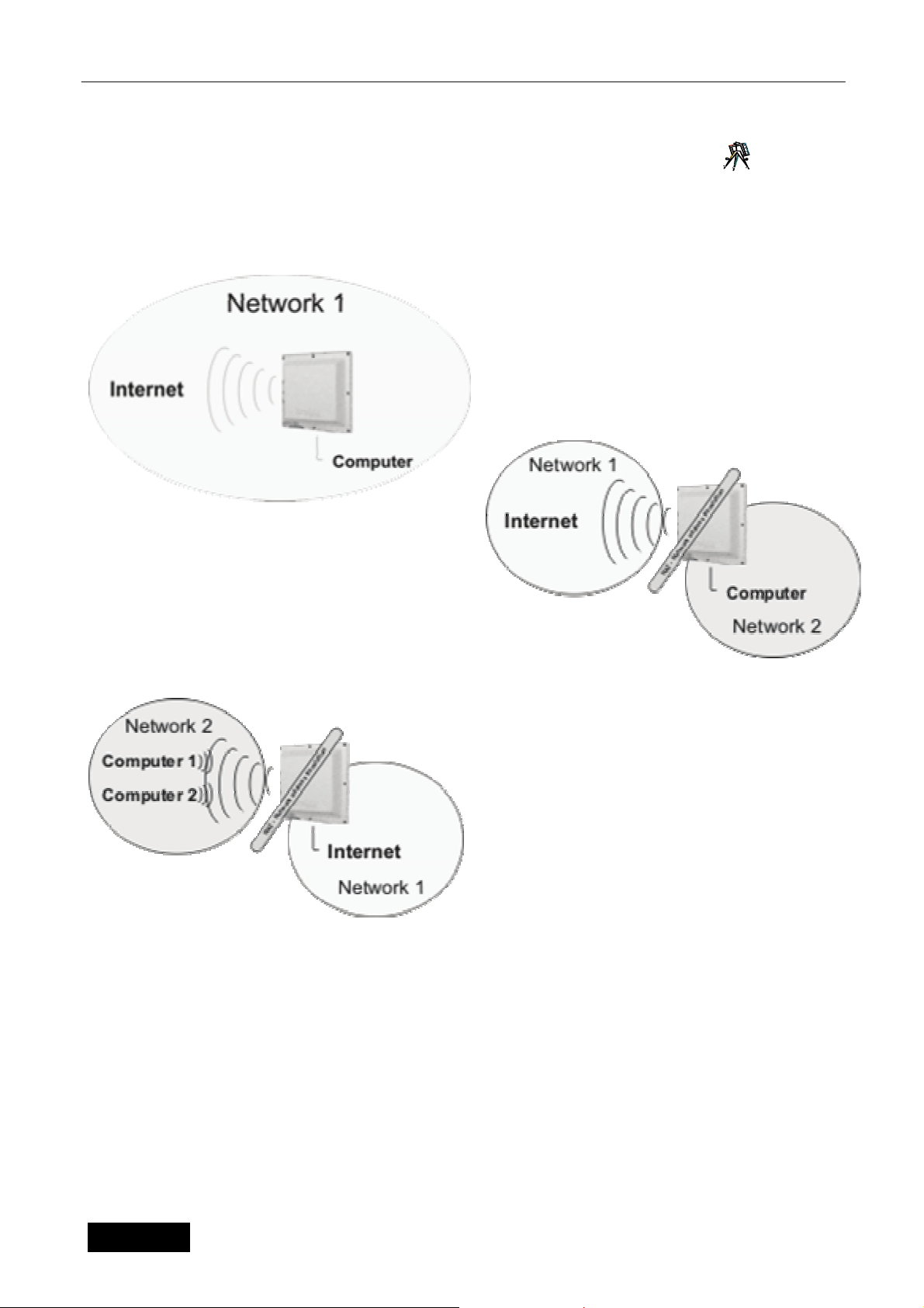
2.3 Setting the operating mode 9
The first step during the setting of the unit is the selection of the operating regime in terms of network
routing. You can access this configuration menu through the Network & Firewall menu, on the Network mode
tab. The unit offers 3 operating modes.
The unit is in 1-BRIDGE mode by default, with
both interfaces at the same level. The unit is
accessible at the same IP address at both
interfaces. This setting is usual when using the
device as an access point and in some cases in
client device mode. All settings related to NAT
operation are not available.
Mode 2 is typically used for the operation of the client
unit. The unit is then connected to the Internet using
the wireless interface. The ports on the PSW-105 can
be used for the connection of client computers. Then
the unit will serves as a default gateway for client
computers. The unit is accessible at the corresponding
IP addresses at the LAN and WAN side for
configuration. This setting is usually combined with the
DHCP server function, which automatically assigns addresses to individual computers.
The typical use of Mode 3 is as a unit used as
common wireless router, for example for the
connection of ADSL, or Ethernet. In this case the
Internet is connected with a cable to the PSW-105
switch port labelled as Ethernet.
Then the client computers are wireless connected.
In this case, the radio has to be set to AP mode.
2.4 Setting of the
wireless part
This multifunctional unit operates in the multiple operation modes of Access Point, Station, WDS
System and AP Bridge-WDS and Repeater. The GWP-207VE unit is the most frequently used in the
operating mode, for which it is designated.
The “Access Point” operating mode is used in the case where the unit serves as the central point of
your wireless network and other wireless adapters are then connected to it in the Station-Infrastructure
Mode.
The “Station” operating mode is divided into two types. The “Station” is used in networks with a
central access point as described above. In the case of using the "Ad Hoc" operating mode, you can create
the network directly between single adapters without participation of the access point. (Peer-to-Peer
communication)
The “WDS System” operating mode (also called BRIDGE) is intended mainly for the connection of
two (“Bridge Point-to-Point”) or more (“Bridge Point-to-Multipoint”) LAN networks.
If the “Repeater" operation mode is set, the unit behaves both as an access point and client adapter
of the master unit in the “AP mode”.
English version
9
Page 10

Configuration of the wireless access point LAN
Why is the WDS System/Bridge mode more suitable for the connection of LAN networks?
When using Station operating modes (both types), the units conforming to WiFi standards change packet
header at second level – that is when the MAC address of the terminal is replaced with a MAC address unit.
In some applications where behind the unit there is more than one terminal, this replacement of the network
address may cause problems. On the contrary, in Bridge modes the unit behaves in a fully transparent
manner also at the second level and the MAC addresses in the header of the packet remain unchanged.
A special case of the WDS System modes is the "WDS Access Point" type. In this operating mode
the unit can be used simultaneously as an Access Point and Bridge connecting LAN networks.
2.4.1 Setting the basic parameters of the wireless connection:
10
The “Basic Setting” in the "Wireless section” menu defines the most important parameters of radio
data transmission. A description of these parameters is shown in the following table:
Parameter Description
Network Name – SSID
(Basic setting for radio module)
Type of operation:
(Basic setting of the radio module)
SSID parameter (up to 31 ASCII characters) represents the key, on the
basis of which there is the connection of individual adapters within the
wireless network. Setting the various network keys can ensure the
functioning of several wireless networks in the same area and within the
same frequency range. It is necessary to use SSID identically in the
access point and all client adapters connected to it. The default value of
this key is “GWP-207VEt” but we recommend changing this setting
during installation. SSID is configured in "Access Point", "Station ADHOC", "Station-Infrastructure", "WDS System" and "AP-Bridge WDS"
operating modes.
This item provides the user with the option to define the operating mode
of the unit only for standard 802.11b, only for 802.11g or for both
Operating channel:
(Basic setting of the radio module)
WiFi standard
(Basic setting of the radio module)
MAC Address:
(WDS/Bridge setting)
Set Security
(WDS/Bridge Setting)
Show statistics:
(WDS/Bridge Setting)
standards at the same time.
Using this setting the user defines the operating channel of the unit. For
use in EU countries (with the exception of Spain) 13 channels are
available in total. Selection of the operating channel is not to be
performed in "Station-Infrastructure" mode as the channel is configured
automatically by the Access Point with same ESSID setting.
Overlapping of Operating Channels
With respect to the division of the frequency range and with regard
to the width of the frequency band used, there is overlapping of individual
channels. Therefore, you get the best results when using WiFi Access
Points so that the units in the respective area are located at least 3 - 5
channels from each other. For example, using channels 1,7,13 when
there is no any interference.
You select the standard for the radio section in this field. For use in then
Czech Republic select ETSI.
In Bridge and WDS System modes it is necessary to define the MAC
addresses of all connected wireless units which the system uses for the
identification of members of the respective Bridge or WDS structure.
In WDS type operating modes you can use this button for setting the
encryption of the transmission for security reasons.
In WDS mode using this button it is possible to view a table displaying
statistical information about individual WDS clients.
English version
10
Page 11

Configuration of the wireless access point LAN
A
Connected Stations:
(Basic setting of the radio module)
Networks Available:
(Basic setting of the radio module)
Click on the “Apply” button in the left corner of the page to save the changes. Now you can switch to set
other parameters or start using the unit.
Clicking on the "View Active Stations" button opens a window with the list
of currently connected clients and the transmission parameters of each
station.
Using this button for scanning of available networks in the Station
operating mode displays the table showing the available wireless
networks. By selecting the wireless network and pressing the Connect
button the unit will be automatically configured for connection to this
network. If the network uses any of the security protocols, you must
manually configure the security.
2.4.2 Advanced setting of radio transmission 11
On this page it is possible to enter the detailed parameters influencing the wireless operation.
Parameters are set by default, so it is not necessary to change them during standard operation, nevertheless
in an interfered environment their optimising may bring an increase in the transmission speed or a lower
error rate.
Parameter Description
Authentication type
This field offers three options. When you choose "Open System", any
station is able to connect to the network regardless of the encryption.
When you choose "Shared key", only the unit can be connected, which
has the same shared key as configured in the security settings. The
"Auto" value combines both these modes.
Threshold of fragmentation
RTS level
Beacon Interval
Line rate
DTIM Period
Preamble type
Hide SSID
The threshold of fragmentation states the maximum size of the packet
during the fragmentation of data to be sent. If too low a value is set, the
performance will decrease.
When the site of the packet is smaller than the RTS threshold, the access
point will not use the RTS/CTS mechanism to send this packet.
The time interval in which the access point broadcasts a beacon.
beacon is used for synchronization of the wireless network.
The line rate states the speed of data transmission used by this access
point. The access point uses for transfer the maximum possible selected
transmission rate.
DTIM is part of the beacon packet which informs units in the energy
saving mode that data transmission will follow. In the case of an increase
in this value, the timeout between the energy saving status and the
transfer into operating mode is increased.
The preamble type defines the length of the CRC block within the
wireless communication. The "Short Preamble" option is suitable for a
high traffic wireless network. The "Long Preamble" option can provide
more reliable communication.
If you disable “Hide SSID”, each wireless station located within the
coverage of this access point can ascertain its presence. If you build a
public wireless network, it is recommended to enable this function.
Enabling “Hide SSID” can provide better security.
English version
11
Page 12

Configuration of the wireless access point LAN
IAPP Function
802.11g Protection
Insulation of wireless clients
802.11b Output Power
802.11g Transmission output
Input Amplification
Click on the Apply button at the bottom of the screen to save the above mentioned configurations.
You can now configure the other sections or start using the Access Point.
If you enable “IAPP”, the access point will automatically broadcast
information regarding any associated wireless stations to its neighbours.
This makes for easy and fluent switching of the wireless station between
access points. If your wireless LAN network contains more than one
access point, it is necessary that these stations will move, so it is
recommended to enable this function. Disabling “IAPP” can provide
better security.
This is also called CTS Protection. It is recommended to enable the
protection mechanism. It enables to decrease the rate of collision
between 802.11b and 802.11g wireless stations. If the protection mode is
enabled, the throughput of the access point will be a bit lower due to the
demand to transmit a high number of frames.
This function is to be used in AP operating mode only. When enabling
this function, the communication between individual clients within a single
AP will be blocked.
This can define the transmission output for operation according to
standard 802.11b, therefore with CCK modulation. When configuring
the output, always check the restrictions for the area where you are
using the unit. Refer to the "Device Usage" chapter when using in
the Czech Republic.
This can define the transmission output for operation according to
802.11g standard, therefore with OFDM modulation. When configuring
the power, always check the restrictions for the area where you are
using the unit. Refer to "Device Usage" chapter when using in
Czech Republic.
Sets the level of amplification for the input pre-amplifier during receipt of
the signal. Setting the higher values enables to receive previously
unavailable wireless networks, nevertheless the interference from the
receiving signal and consequently the transmission error rate increases.
2.4.3 Security
12
This Access Point provides all security functions of a wireless LAN network, including WEP, IEEE
802.11x, IEEE 802.11x with WEP, WPA with a pre-shared key and WPA with RADIUS. These security
functions prevent unauthorized access to your wireless LAN network. Make sure that all wireless stations
use the same security function.
In addition to standard types of encryption, it is always possible to turn on the pre-authentication with the
Radius server and the 802.1x standard. IEEE 802.1x is an authentication protocol. Each user must use a
valid account to login to this Access Point before accessing the wireless LAN. The authentication is
performed by a RADIUS server. This mode only authenticates a user by IEEE 802.1x, but it does not encrypt
the data during communication. You can use 802.1 x without encryption in "AP mode" and “AP Bridge-WDS
mode”.
Note: This access point can behave both as a station and AP in "AP Bridge-WDS mode". The security
settings only apply to the AP function in the "AP Bridge-WDS mode".
English version
12
Page 13

Configuration of the wireless access point LAN
Parameter Description
Security Type:
Format of WEP Key :
WEP Key:
Shared Key Format:
Shared key:
You can select the type of security which will be used. WEP, WPA and
WPA with RADIUS support is available.
This field is used when using WEP Encryption. It indicates the format for
entering keys. You can choose ASCII or Hexadecimal format.
Default key value for WEP Encryption.
In this field you can choose the WPA key format. Again you can select
ASCII or Hexadecimal format.
Key for data encryption in the WPA system.
2.4.3.1 WEP encryption 13
Use the “WEP encryption” page to set the WEP encryption keys. A description of the individual
parameters is in the table below:
Parameter Description
Key length 64 bit and 128 bit key for encryption of transmitted data can be selected.
A longer WEP key provides a higher level of security, but lowers
throughput.
Key format For the WEP key, ASCII characters (alphanumeric format) or
hexadecimal digits (in “A-F”, “a-f” and “0-9” range) can be selected. For
Example:
ASCII characters: guest
Hexadecimal digits 12345abcde
Default key Select one of four keys to encrypt your data. Use only the key selected in
Encryption key 1 – 4 The WEP keys are used for encryption of the data transmitted in the
Click on the Apply button at the bottom of the screen to save the above configurations. You can now
configure other advance sections or start using the Access Point.
“Default key”.
wireless network. Fill in the text box by following the rules below.
64-bit WEP: input 10-digit Hex values (in the “A-F”, “a-f” and “0-9” range)
or 5-digit ASCII characters as the encryption keys.
128-bit WEP: input 26-digit Hex values (in the “A-F”, “a-f” and “0-9”
range) or 10-digit ASCII characters as the encryption keys.
2.4.3.2 WPA/WPA2 14
Wi-Fi Protected Access (WPA) is an advanced security standard. You can use a pre-shared key to
authenticate wireless stations and encrypt data during communication. After changes of encryption keys are
performed using TKIP or CCMP (AES) methods. Therefore the encryption key is not easy to be broken by
hackers. This can substantially improve wireless network security. You can use WPA encryption with a preshared key in the “AP mode”, “Station-AD HOC mode”, “Station-Infrastructure mode” and “AP Bridge-WDS
mode”.
Parameter Description
Authentication Mode You can select pre-shared key authentication or authentication with
Radius server. In this case, the Radius server will be used as set in the
upper part of the screen.
Key format For a pre-shared WEP key it is possible to select for the input phrase
ASCII characters (alphanumeric format) or hexadecimal digits (in “A-F”,
“a-f” and “0-9” range). For Example:
Input phrase: iamguest
Hexadecimal digits 1234567890abcdef
English version
13
Page 14

Configuration of the wireless access point LAN
Shared key A pre-shared key is used for authentication end encryption of the data
transmitted in the wireless network. Fill in the text box according to the
following rules. Hex: input 64-digit Hex values (in the “A-F”, “a-f” and “0-9”
range) or as pre-shared encryption keys or minimum 8-digit input phrase.
Click on the Apply button at the bottom of the screen to save the above configurations. You can now
configure other advance sections or start using the Access Point.
2.4.4 Filtering of MAC addresses 15
This Access Point provides MAC Address Filtering, which prevents unknown (unauthorized) MAC
Addresses from accessing your wireless network.
Parameter Description
MAC Address Filter Setting
MAC Address Filtering Table
Add MAC address into the table
Remove selected MAC
addresses
Remove all
Click on the Apply button at the bottom of the screen to save the above configurations. You can now
configure other advance sections or start using the Access Point.
Enables or disables the MAC Address Filtering function.
This table contains records of the MAC addresses of the wireless stations
you want to allow to access your network. The “Comment” field is the
description of the wireless station associated with the “MAC Address”
and is helpful for you to recognize the wireless station.
In the bottom “New” area, fill in the “MAC Address” and the “Comment” of
the wireless station to be added and then click on “Add”. Then this
wireless station will be added into the “MAC Address Filtering Table”
above.
If you want to remove some MAC address from the “MAC Address
Filtering Table”, select the MAC addresses you want to remove in the
table and then click on “Delete Selected”. If you want remove all MAC
addresses from the table, just click on the “Delete All” button.
Click on the "Remove All" button to clear the whole table.
2.5 IP setting
You can define all parameters associated with TCP/IP in the Ethernet section in the Main Menu.
2.5.1 LAN port TCP/IP setting 16
On this page you can set the TCP/IP parameters related to the LAN interface, i.e. the interface
directed to the local network in ROUTER mode. This setting will also be used in BRIDGE operation. In
addition to standard TCP/IP parameters such as IP address, network mask, default gateway, you can also
define DHCP related parameters here.
DHCP can be used in several operating modes:
DHCP Client: The device is waiting for the parent DHCP Server to assign its TCP/IP parameters by DHCP
Server in this mode.
DHCP Server: Using this operation mode the unit itself provides TCP/IP settings information for other clients
and the IP Address, Mask and Gateway parameters are delivered. The "DHCP Address Range" field is used
for definition of the addresses that will be assigned to clients. Click on the "Show Client” button to display the
currently assigned address list.
DHCP Disabled: DHCP service is disabled in this case.
Another setting possibility is to enable the Spanning Tree routing protocol defined by the 802.1d standard.
The MAC address cloning feature is used for changing of the configuration of the HW address of the LAN
interface.
English version
14
Page 15

Configuration of the wireless access point LAN
2.5.2 WAN port TCP/IP setting
On this page you can define the settings for the wireless interface, directed to the Internet. These settings
will not be used when the unit is in BRIDGE mode. This page is dynamic and changes according to the
Internet connection type currently selected. The suitable connection type is determined according to the
application mode or your connection provider. There are 5 types in total:
2.5.2.1 Static IP address
The IP Address is set manually to the device in this mode. In addition to the IP Address, Gateway and
Mask you can set three DNS servers to back each other up. The last item entered is the possible MAC
Address definition for the WAN interface.
2.5.2.2 DHCP Client
When using the DHCP Client setting, you can define the manner of assigning DNS server information, or
WAN Port MAC Address only. The other TCP/IP parameters are assigned automatically by the parent DHCP
server.
2.5.2.3 PPPoE
PPPoE (Point-To-Point Protocol over Ethernet) settings are often used by Internet connection providers.
It is simple method of authenticated connection, secured with the name and password specified in the
configuration. In addition, the type of connection is defined (Permanent, At Request, Manual), automatic
disconnect timeout and maximum transmit packet length. You can also manually define the MAC interface
Addresses.
2.5.2.4 PPTP
PPTP setting is used for the automatic connection to a Virtual Private Network. Connection is defined by
the Server IP Address, Username and Password. Again you can define the MTU, DNS servers and interface
MAC Addresses, next MPPE or MSCHAP encryption type. Contact the VPN network administrator to acquire
the parameters for connection.
2.5.2.5 PPTP+DHCP
This option is used for connection to the VPN network as before, although the local IP address is
acquired from the DHCP server located in the given VPN.
2.5.3 Gateway and Routing 17
The page “Gateway and routing” is used for defining static items of the routing table to ensure the correct
functioning of the Unit in “Router mode”. To set these parameters you need to know the network structure
and where the unit is installed. “Default Gateway” defines the border router, to which all packets with nondefined routing will be sent (an automatic or manually set up routing rule).
English version
15
Page 16

Configuration of the wireless access point LAN
2.6 Network and Firewall
Next to the network mode is the basic setting described in chapter 3.3, the following options are shown in
the “Network and Firewall” tab:
2.6.1 IP/MAC Address Blocking, Port Blocking 18
With regard to the identical direction of the configuration possibilities of “IP address Blocking" and "MAC
address Blocking" tabs, there is only the view for the first one.
“IP address Blocking” table items are used for limitation of the throughput of some packets directed from the
internal network, which reduces the abuse of your internet connection as well as the leakage of information
from some stations in your network.
“Blocking MAC address” table items enable to prevent data sending from your network by definition of the
rights bound with the HW addresses of individual devices.
“Blocking Port” table items allow restricting the range of TCP/IP or UDP ports through the Unit. It enables to
limit the accessibility of certain services provided from an external network.
For easy orientation in the created tables it is possible to create for each entered item a note with a
description of the respective rule.
2.6.2 Port forwarding 19
Entries in this table control the forwarding of incoming ports to the external gateway interface to any
IP in the internal network. It allows using the chosen computers in the internal network as servers or allows
their remote administration access. The symbol “S” represents a forward change of the origin address which
is necessary for some programmes. The symbol “C” indicates a change of the target port (the second value
is the number of the target port).
2.6.3 Setting DMZ (Demilitarized Zone)
The demilitarized Zone function allows you to configure that one computer in your network is directly
accessible from Internet. All services will be routed to this computer, except the services provided by the
router itself.
2.7 Services
In the Main Menu "Control" tab there are functions linked to the correct unit operation, software equipment
update functions, password changes, etc.
2.7.1 Rate limit 20
On this page it is possible to define the rate limits valid for whole unit. The upload and download direction is
always considered from the viewpoint of the client.
For advanced users: If the unit is in BRIDGE operation mode, upload means Ethernet interface broadcast
limit and download is the wireless interface broadcast limit. In ROUTER operating mode the tasks of the
individual interfaces are reversed.
2.7.2 DDNS setting 21
Dynamic DNS is a service, which allows registering a valid domain for changing (dynamic) IP Address. This
unit supports 2 providers of this service, DynDNS and TZO. TZO provides a 30-day free trial version of this
service. Refer to
www.tzo.com for more information.
English version
16
Page 17

Configuration of the wireless access point LAN
2.7.3 Tile server 22
The "Time Server" tab allows you to configure synchronization with a NTP Time server. You can select a
server from the prepared list or define your own.
2.7.4 Watchdog/Restart 23
Due to operating reasons it is sometimes suitable to restart the unit at automatically set intervals. In this case
use the "Watchdog/Restart" tab settings. This enables this function and also defines the interval for
automatic restart.
Another possibility is to restart the unit when there is a lost connection with the respective IP address. It is
necessary to define the test interval and one or two IP Addresses. IP address 1 is always checked during the
test and when the packet loss is more than 20%, it proceeds to test IP address 2. If the IP address testing
passes, IP address 2 is not tested. When neither IP address 2 is available, the unit will automatically restart.
2.7.5 Network test 24
The "Network Test" tab includes standard TCP/IP network testing tools. It provides Ping, Arping and
Traceroute tools, including the corresponding parameters. The test result is displayed in the lower window.
After entering the parameters use the "Send" button.
English version
17
Page 18

Configuration of the wireless access point LAN
Chapter 3 Administration
3.1.1 Changing password 25
The "Change of Password" tab, as results from the name, allows you to change access passwords for unit
control.
The “Super-user Off” parameter can block the possibility to connect to the unit with a non-public password
set by producer.
3.1.2 Save/Restore configuration 26
The "Backup/Restore Configuration" screen enables to save the current configuration settings of the access
point. The saving of the configuration provides further security and a suitable manner of solving potential
problems with the access point when it is necessary to restore the default factory settings. If you save the
configuration setting, you can reload the saved configuration to the access point using the "Restore" button.
In the case of serious problems it is possible to use the "Restore the default factory settings" option. This
option resets all the configuration values of the Access Point to the default factory values.
3.1.3 Update 27
The "Update" page allows you to update the software used by the unit, in the case that the unit is not
working as expected or new operation software is released. When you select the file to update, use the
"Restore" button. The update can take up to 180 seconds – do not interrupt the power of the unit during
this time. It is recommended to perform the update through metallic cable connection only.
When you connect to the unit using low data throughput connection, mark the "Slow Upload" tab. This will
make the transmission timeout longer.
3.1.4 Web interface 28
This page is used for configuration of the interface parameters for the unit service and its accessibility
from each port. In addition, you can define the TCP/IP port for access, which is appropriate, for example in
such cases, when it is necessary to release port 80 for reason of the www server in DMZ operation or by
port forwarding.
3.2 Restart
If the unit does not work correctly you can remotely restart the operating system. Your settings will not
be changed. You can perform the reset by clicking on the Restart button in the Main Menu. Restarting is
instant, without confirmation dialog.
English version
18
Page 19

Introduction
Chapter 4 Troubleshooting
This chapter provides solutions to problems usually occurring during the installation and operation of the
access point.
1. How to manually find your PC’s IP and MAC Address?
1) In Windows, open the Command Prompt program
2) Enter Ipconfig /all and press Enter.
y Your PC’s IP address is the one entitled IP address.
y Your PC’s MAC address is entitled Physical address.
2. What is Ad-hoc?
An Ad-hoc wireless LAN is a group of computers, each with a WLAN adapter, connected as an
independent wireless LAN.
3. What is Infrastructure?
Configuration of the infrastructure means an integrated wireless and wired LAN (interconnected by
cable).
4. What is BSS ID?
A group of wireless stations and an access point comprise a Basic Service Set (BSS). Computers in a
BSS must be configured with the same BSSID.
5. What is ESSID?
An Infrastructure configuration can also support roaming capability for mobile workers. More than one
BSS can be configured as an Extended Service Set (ESS). Users within an ESS can roam freely
between BSSs while maintaining a continuous connection to the wireless network stations and the
Wireless LAN Access Points.
6. Can data be intercepted while transmitting over the air?
WLAN features two-fold protection in security. On the hardware side, as with Direct Sequence Spread
Spectrum technology, it has the inherent scrambling security feature. On the software side, the WLAN
network offers an encryption function (WEP, WPA, WPA2) to enhance security and access control.
7. What is WEP?
WEP stands for Wired Equivalent Privacy, a data privacy mechanism based on a 64(40)-bit shared key
algorithm.
8. What is WPA?
WPA is an acronym for Wi-Fi Protected Access. It is a security protocol for 802.11 wireless networks.
WPA can provide data protection with the use of encryption and the use of access controls and user
authentication.
9. What is WPA2?
In addition to WPA, WPA2 provides a stronger encryption mechanism through Advanced Encryption
Standard (AES).
10. What is a MAC Address?
The Media Access Control (MAC) address is a unique number assigned by the manufacturer to any
Ethernet networking device, such as a network adapter, that allows the network to identify it at the
hardware level. For all practical purposes, this number is usually permanent. Unlike IP addresses,
which can change every time a computer logs on to the network, the MAC address of a device stays
the same, making it a valuable identifier for the network.
Česká verze
1
Page 20

Introduction
Straight
C
o
Multifunkční přístupový bod
r
e
GWP-106VE
IEEE 802.11b/g
54Mbps
Česká verze
Uživatelský manuál
2
Page 21

Introduction
Obsah
Kapitola 1 Úvodem .................................................................................................................................................4
1.1 Obsah balení ................................................................................................................................................ 4
1.2 Funkce jednotky........................................................................................................................................... 4
1.3 Specifikace................................................................................................................................................... 4
1.4 Popis a instalace jednotky...........................................................................................................................5
1.4.1 Venkovní část - ODU ................................................................................................................... 4
1.4.2 Vnitřní část – IDU ........................................................................................................................ 4
Kapitola 2 Konfigurace jednotky .......................................................................................................................... 8
2.1 Příprava konfigurace.................................................................................................................................... 8
2.1.1 Nastavení Vašeho PC ................................................................................................................... 7
2.2 Statistiky .............................................................................................................................................8
2.2.1 Stav jednotky .............................................................................................................................. 9
2.2.2 Dostupné sítě ................................................................................................................................8
2.2.3 Data .............................................................................................................................................. 8
2.2.4 Bezdrátová připojení..................................................................................................................... 8
2.2.5 Klienti DHCP ...............................................................................................................................8
2.2.6 WDS Připojení.............................................................................................................................. 8
2.2.7 Směrovací tabulka ........................................................................................................................ 8
2.2.8 ARP Tabulka ................................................................................................................................ 8
2.3 Nastavení režimu provozu ........................................................................................................................... 9
2.4 Nastavení bezdrátové části......................................................................................................................... 10
2.4.1 Nastavení základních parametrů bezdrátového přenosu................................................. 10
2.4.2 Pokročilá nastavení rádiového přenosu ............................................................................... 11
2.4.3 Zabezpečení............................................................................................................................. 12
2.4.4 Filtrování MAC adres............................................................................................................... 14
2.5 Nastavení IP...............................................................................................................................................14
2.5.1 Nastavení TCP/IP portu LAN ................................................................................................. 14
2.5.2 Nastavení TCP/IP portu WAN................................................................................................ 15
2.5.3 Brána a směrování ...................................................................................................................... 15
2.6 Síť a Firewall ............................................................................................................................................. 16
2.6.1 Blokování IP/MAC adres, Blokování portů ............................................................................... 16
2.6.2 Směrování portů ......................................................................................................................... 16
2.6.3 Nastavení DMZ (Demilitarizovaná zóna).............................................................................. 17
2.7 Služby ........................................................................................................................................................ 17
2.7.1 Limit rychlosti ............................................................................................................................16
2.7.2 Nastavení DDNS...................................................................................................................... 16
2.7.3 Časový server........................................................................................................................... 17
2.7.4 Watchdog/Restart .................................................................................................................... 17
2.7.5 Test sítě..................................................................................................................................... 17
2.8 Správa ........................................................................................................................................................ 19
2.8.1 Změna hesla.............................................................................................................................18
2.8.2 Uložení/Obnovení konfigurace...............................................................................................18
2.8.3 Aktualizace................................................................................................................................ 18
2.8.4 Rozhraní www .......................................................................................................................... 18
2.9 Restart........................................................................................................................................................ 18
Kapitola 3 Odstraňování potíží............................................................................................................................. 1
Česká verze
3
Page 22

Introduction
Chapter 5 Úvodem
Děkujeme za zakoupení bezdrátové klientské jednotky GWP-207VE. Jedná se o jednotku pro
budování sítí dle standardu 802.11b či 802.11g. Bezdrátové sítě jsou tvořeny přístupovými body (Jednotka v
režimu “Access Point”) a klientskými zařízeními (Jednotka v režimu Infrastructure). Pro propojení více
počítačů bez přístupového bodu lze použít nastavení AD-HOC, pro vybudování spoje Bod-Bod pak režim
WDS/Bridge.
Tato jednotka podporuje bezpečnostní systémy WEP, WPA, ESSID a filtr MAC adres pro zajištění
bezpečnosti bezdrátové sítě. Díky těmto bezpečnostním standardům můžete zabránit neautorizovanému
přístupu do Vaší bezdrátové sítě.
Tato jednotka je vybavena integrovanou panelovou anténou se ziskem 14 dB. Zařízení umožňuje pomocí
www rozhraní řízení celkového vyzářeného výkonu, tedy výkonu který již zahrnuje zisk samotné antény.
Jednotka nabízí velmi snadné ovládání pomocí libovolného webového prohlížeče, které je
lokalizováno do několika jazyků. Pro aktuální seznam jazykových modifikací uživatelského rozhraní laskavě
kontaktujte svého dodavatele, případně jej naleznete i na stránkách výrobce www.straightcore.net
Firmware (ovládací program jednotky) je vyvinut s důrazem na použití v rozsáhlých bezdrátových
sítích. Kryt jednotky je navržen pro použití mimo budovy s dostatečnou ochranou proti stékající vodě a
dalším povětrnostním vlivům. Pro snadné nastavení je možné k jednotce připojit zaměřovač GWP-HDF,
jehož popis a použití naleznete v tomto manuálu.
Poznámka: Tento manuál je napsán pro verzi firmware 1.0.6. U novějších firmware se mohou objevit funkce,
které nejsou v této verzi manuálu podchyceny.
Obrázky nalezente v barevné p
říloze na konci manuálu. Číslo obrázku, vztahující se k dané kapitole,
se nachází vždy vedle symbolu
5.1 Obsah balení
Balení jednotky obsahuje následující části:
y Jeden rychlý instalační manuál
y Jeden přístupový bod
y Jeden napájecí adaptér
y Jeden switch PSW-105 se systémem POE
5.2 Funkce jednotky
y Kompatibilní se specifikací IEEE 802.11b/g (DSSS) 2.4GHz.
y Vodotěsné provedení s integrovanou anténou 14 dB
y Systém napájení po ethernetu PoE
y Vysoká rychlost přenosu až 54Mbit/sec.
y Jednoduchá integrace do stávající LAN sítě.
y Automatické snižovaní přístupové rychlosti při zarušeném prostředí.
y Šifrovací funkce 64/128-bit WEP a WPA pro zabezpečení bezdrátového přenosu.
y Integrovaný DHCP server pro automatické přidělování IP adres.
y Ovládání pomocí www prohlížeče.
5.3 Specifikace
y Standardy: IEEE 802.11b/g (Bezdrátová část), IEEE 802.3 (Lan část)
y Přenosové rychlosti: 54/48/36/24/18/12/11/9/6/5.5/2/1Mbit/sec s automatickým snižováním v
zarušeném prostředí
y Bezpečnost: 64/128-bitové WEP a WPA šifrování přenosu
y Frekvenční rozsah: 2.400~2.4835GHz (ISM pásmo)
Česká verze
4
Page 23

Introduction
y Modulace:
802.11b - CCK@11/5.5Mbps, DQPSK@2Mbps a DBPSK@1Mbps
802.11g – BPSK, SPSK, 16QAM, 64QAM
y Bezdrátová technologie: DSSS pro 802.11b, OFDM pro 802.11g
y Anténa: Externí odpojitelný dipól 2dB (konektor RP-SMA)
y Síťový konektor:
ODU-10/100Mbps RJ-45 x 2, GWP-HDF port (USB connector) x1
IDU – 5xRJ45 (PoE standardně na portu 1, volitelně 2,3,4)
y Napájení: 12V DC
y Vysokofrekvenční výkon: max 19.8 dBmW
y LED diody:
ODU - Napájení, Link (Na konektorech RJ-45)
IDU - Napájení, 4x LAN Linka/Aktivita/PoE systém, 1x LAN Linka/Aktivita
y Teplotní rozsah:
Provoz: -35°C~65°C
Skladování: -35°C~70°C
y Vlhkost: 10-90% (Nekondenzující)
y Certifikace: FCC, CE
5.4 Popis a instalace jednotky
5.4.1 Venkovní část - ODU
Část jednotky určená k umístění na instalační stožár. V přední části obsahuje integrovanou anténu 12 dB.
5.4.1.1 Ethernet/POE port
Ve spodní části venkovní jednotky naleznete vodotěsnou část zakrytou plastovou krytkou. V této části se
nachází port pro konektor RJ-45 a tlačítko Reset. Pro propojení jednotky s interní částí je třeba vždy využít
plně osazeného stíněného kabelu STP kategorie 5,5e či 6. V případě využití nestíněného kabelu může dojít
vlivem statického výboje k poškození jednotky či připojeného počítače. Po zasunutí konektoru do portu
dbejte na správnou instalaci vodě odolné krytky a její upevnění přiloženým šroubkem.
Jednotku připevněte na stožár pomocí držáku a vidlice, které naleznete v příslušenství. Připevníte-li
jednotku k držáku tak, aby LED diody na přední straně byly navrchu, je jednotka ve vertikální polarizaci. Pro
montáž v polarizaci horizontální otočte držák o 90 stupňů tak, aby byl ethernetový kabel chráněn prolisem
v krytce proti stékající vodě. Následně středovým šroubem připojte plastovou vidlici a po připevnění celé
jednotky na stožár šroub dotáhněte tak, aby sklon jednotky co nejlépe odpovídal směru umístění vysílacího
bodu, ke kterému se bude GWP-106VE připojovat.
5.4.1.2 Tlačítko Reset
Jednotka je vybavena tlačítkem sloužícím k jejímu restartu či uvedení do továrního nastavení. Toto
tlačítko naleznete vpravo od konektoru RJ-45. Pro jeho stisknutí použijte kuličkové pero či jiný vhodný
nástroj. Použití je následující:
• Stisknutím na dobu kratší než 4 sekundy dojde k restartu přístupového bodu. Konfigurační
parametry zůstanou v tomto případě zachovány.
• V případě ztráty hesla či IP adresy je možné sepnout kontakt na dobu delší než 4 sekundy. V
tom případě dojde k obnovení továrního nastavení a restartu přístupového bodu na výchozí
adrese 192.168.1.1 a nebude chráněna uživatelským jménem ani heslem.
5.4.2 Vnitřní část – IDU
Vnitřní část jednotky se dodává ve dvou provedeních, která odpovídají následujícím popisům:
Česká verze
5
Page 24

Introduction
5.4.2.1 Standardní Power Injector
V základním provedení je jednotka dodávána se standardním injectorem bez integrovaného switche.
Jeho zapojení je snadné. Do portu označeného LAN připojte ethernetový kabel z Vašeho PC nebo switche.
Port POE je určen k připojení kabelu vedoucího k samotné jednotce ODU. Do portu popsaného DC zapojte
dodaný síťový adaptér – tím je instalace hotova. Pozor, při chybném zapojení kabelů do jednotlivých
portů může dojít k závažnému poškození Vašeho switche či počítače. Proto pro toto připojení
doporučujeme používat kabel Cat.3 4 či 5 se zapojenými kontakty pouze 1, 2, 3 a 6. V tomto případě
poškození nehrozí, neboť POE systém využívá přenosu na kontaktech 4/5 a 7/8 jak je schematicky
znázorněno na horní straně POE injectoru.
K montáži injectoru na stěnu je možné použít boční úchyty a malé šroubky, které však nejsou
součástí dodávky. Rozteč montážních otvorů je 68 mm.
5.4.2.2 PSW-105/205
Jako volitelné příslušenství může být k jednotce GWP-106VE dodán injector PSW-105/205
s integrovaným 4-portovým switchem. Tato varianta je vybavena LED diodami pro kontrolu funkce. Popis
stavu a funkce jednotlivých LED diod naleznete v následující tabulce:
LED Barva Stav Popis
Power Oranžová
Zelená
1-4/POE
5 Zelená
Oranžová
Červená
Svítí Napájení jednotky připojeno.
Nesvítí Není napájení.
Nesvítí Linka odpojena,POE neaktivní
Červená Linka odpojena,POE aktivní pro daný port
Oranžová svítí Linka připojena,POE aktivní pro daný port
Oranžová bliká Linka připojena,POE aktivní, přenos dat
Zelená svítí Linka připojena, POE neaktivní
Zelená bliká Linka připojena, POE neaktivní, přenos dat
Svítí
Bliká Linka vysílá či přijímá data.
Nesvítí Linka odpojena
Linka připojena.
5.4.2.2.1. POE Systém
IDU PSW-105 je vybavena systémem POE (Power-over-ethernet). Ve standardní konfiguraci je PoE aktivní
pouze na portu č.1, který je určen k napájení jednotky. Ve speciálních případech je propojením přepínače
J1 na desce switche možné zapnout napájení i na portech 2-4 a napájet tedy jedním PSW-105 switchem
až 4 externí jednotky (v tomto případě je třeba vyměnit dodávaný síťový zdroj za zdroj 12V/2A). Další
možností využití tohoto režimu je například instalace jednoho switche u PC s aktivním POE portem 1 a
napájení vzdáleného switche v režimu 4 POE portů pomocí POE systému. Zbývající 3 porty pak lze využít
k připojení 3 externích jednotek GWP-207VE.
Pro rychlé zjištění konfigurace PSW-105 připojte pouze napájecí napětí. Porty, na kterých je aktivní POE
systém, jsou označeny trvale svítící červenou LED diodou.
5.4.2.2.2. Napájení IDU/Zapojení více jednotek
Konektor DC-12V slouží pro připojení napájecího napětí. S jednotkou je standardně dodáván zdroj
12V/500mA, který je dostačující pro provoz switche a jedné jednotky na kabelu do délky 15m. V případě
provozu na delším kabelu lze pro napájení použít stabilizovaný zdroj max.18V. Zvýšením vstupního napětí
lze zajistit stabilní provoz až na 70m ethernetového vedení. V případě připojování více jednotek k jednomu
PSW-105 je třeba naopak zvyšovat vstupní proud. Pro každou připojenou jednotku je třeba počítat
s proudem 400mA a pro každý dálkově napájený switch s proudem 100mA.
Česká verze
6
Page 25

Introduction
5.4.2.2.3. Ethernet porty 1/5
Konektor pro připojení zařízení do běžné LAN počítačové sítě kabelem Cat.5,5E či Cat.6. Pozor, k portům
s aktivním POE systémem připojujte pouze externí jednotky StraightCore. Připojení jiného zařízení může
vést k poškození switche ale i připojeného zařízení.
.
Česká verze
7
Page 26

Konfigurace bezdrátového přístupového bodu LAN
Chapter 6 Konfigurace jednotky
6.1 Příprava konfigurace
Tato jednotka poskytuje snadné ovládání pomocí www prohlížeče. Pro přístup ke konfiguraci následujte níže
popsané kroky
6.1.1 Nastavení Vašeho PC
Ujistěte se, že Váš počítač je nastaven ve stejném IP rozsahu jako bezdrátová jednotka. Tovární
TCP/IP nastavení jednotky je následující.
Výchozí IP adresa: 192.168.1.1
Výchozí maska: 255.255.255.0
Konfigurace TCP/IP parametrů Vašeho PC.
1a) Windows 95/98/Me
9. Stiskněte tlačítko Start a vyberte záložku Nastavení, poté Ovládací panely. Objeví se okno
Ovládací panely.
10. Poklepejte na ikonu Síťová připojení.
11. Zkontrolujte zobrazené položky. Pokud není protokol TCP/IP nainstalován, stiskněte tlačítko
Přidat. Pokud TCP/IP již nainstalováno je, pokračujte na krok 6.
12. V dialogu Typ součásti sítě vyberte Protokol a stiskněte Přidat.
13. V okně Typ síťového protokolu vyberte TCP/IP a opět stiskněte Přidat. Pro dokončení
instalace můžete potřebovat instalační disk operačního systému.
14. Po instalaci protokolu TCP/IP se opět vřaďte do seznamu součástí sítě, označte TCP/IP
protokol a stiskněte tlačítko Vlastnosti.
15. Zkontrolujte všechny tabulky a vyplňte je dle následujících parametrů:
• Vazby: Označte Klient sítě Microsoft a Sdílení souborů a tiskáren.
• Brána: Všechna pole zůstávají prázdná.
• Konfigurace DNS: Vyberte Nepoužívat DNS.
• WINS: Vyberte Nepoužívat WINS.
• IP Adresa: Vyberte Zadat IP adresu. Zadejte IP adresu a masku dle následujícího
příkladu
9 IP Adresa: 192.168.1.3 (jakákoliv IP adresa v rozsahu
192.168.1.2~192.168.1.254 je možná, nenastavujte 192.168.1.1)
9 Maska sítě: 255.255.255.0
16. Restartujte počítač. Po restartu bude mít počítač Vámi zadanou IP adresu
1b) Windows XP
1: Stiskněte tlačítko Start a vyberte Ovládací panely, poté klikněte na Síťová připojení. Objeví se
okno Síťová připojení
2: Poklepejte na ikonu Připojení k místní síti.
3: V následujícím okně vyberte ze seznamu TCP/IP a stiskněte tlačítko Vlastnosti.
4: Do otevřeného okna Protokol sítě Internet (TCP/IP) – vlastnosti vyplňte následující údaje:
Adresa IP: 192.168.1.2
Maska podsítě: 255.255.255.0
5: Stiskněte tlačítko OK. Vaše PC je nyní nastaveno pro připojení k jednotce.
Česká verze
8
Page 27
Konfigurace bezdrátového přístupového bodu LAN
Zadejte IP adresu jednotky 192.168.1.1 do Vašeho www prohlížeče pro přístup ke konfiguraci. Ve
výchozí konfiguraci jednotka není chráněna heslem a jménem. Nyní můžete jednotku GWP-106VE
nakonfigurovat pro připojení k přístupovému bodu.
6.2 Statistiky 1
Na obrázku 1 v obrazové příloze vidíte úvodní stránku po vstupu do ovládání jednotky. K jednotlivým
konfiguračním parametrům přistupujete pomocí dvojice nabídek. V levé horní části pod logem výrobce se
nachází primární nabídka s hlavními položkami. Nad samotnou obrazovkou je pak umístěna dynamická
nabídka. Její obsah se mění v závislosti na aktuálně vybrané položce hlavní nabídky.
6.2.1 Stav jednotky
Na této úvodní obrazovce jsou k dispozici informace o současném nastavení jednotky, době běhu od
posledního restartování, verzi hardware i software jednotky, nastaveném síťovém klíči, provozním módu
jednotky atd. Důležitou informací zde, kterou budete potřebovat pro nastavení Vaší bezdrátové sítě, je údaj
“WiFi MAC adresa – BSSID”. Jedná se o síťovou adresu bezdrátové části jednotky, kterou se jednotka hlásí
do Vaší bezdrátové sítě. Jestliže užíváte jednotku v módu “Stanice – Infrastruktura”, pak je třeba v případě
filtrování MAC adres na přístupovém bodu, k němuž se napojujete, zajistit propuštění této MAC adresy
filtrováním.
6.2.2 Dostupné sítě 2
Pokud je jednotka v některém z operačních módů typu “Stanice”, dojde po stisknutí tlačítka „Obnovit“
na stránce “Dostupné sítě” k vyhledání všech dostupných bezdrátových sítí. Tabulka poskytuje informace o
SSID síti, MAC adrese nalezené jednotky, provozním kanálu, typu sítě a síle signálu. Po vybrání dané sítě v
pravém sloupci můžete nastavit parametry dané sítě tlačítkem “Připojit”. Jestliže síť využívá některý z
šifrovacích standardů, je nutné bezpečnostní parametry nastavit ručně.
6.2.3 Data 3
Na stránce „Data“ je možné zjistit statistiky přijatých a odeslaných paketů pro jednotlivá rozhraní jednotky od
jejího posledního restartování.
6.2.4 Bezdrátová připojení 4
Na stránce bezdrátová připojení lze v režimu Access Point získat informace o aktuálně připojených klientských
stanicích, množství jimi přenesených dat, ale i síle signálu. Klepnutím na tlačítko „rozšířené“ bude tabulka obohacena o
další podrobné parametry o komunikaci s jednotlivými stanicemi.
6.2.5 Klienti DHCP
5
Je-li na jednotce zapnut DHCP server, informuje tabulka na stránce klienti DHCP o aktuálně přiřazených IP
adresách jednotlivým klientům.
6.2.6 WDS Připojení 6
Je-li jednotka nakonfigurována jako součást systému WDS, ukazuje tabulka na této stránce parametry
jednotlivých stanic systému WDS.
6.2.7 Směrovací tabulka 7
Na stránce „Směrovací tabulka“ naleznete aktuální pravidla směrování (routing) jednotky. Tato pravidla lze
upravit v menu statické cesty
6.2.8 ARP tabulka 8
Stránka ARP tabulka informuje o MAC adresách připojených zařízení jak na bezdrátové, tak na metalické
straně jednotky.
Česká verze
9
Page 28
Konfigurace bezdrátového přístupového bodu LAN
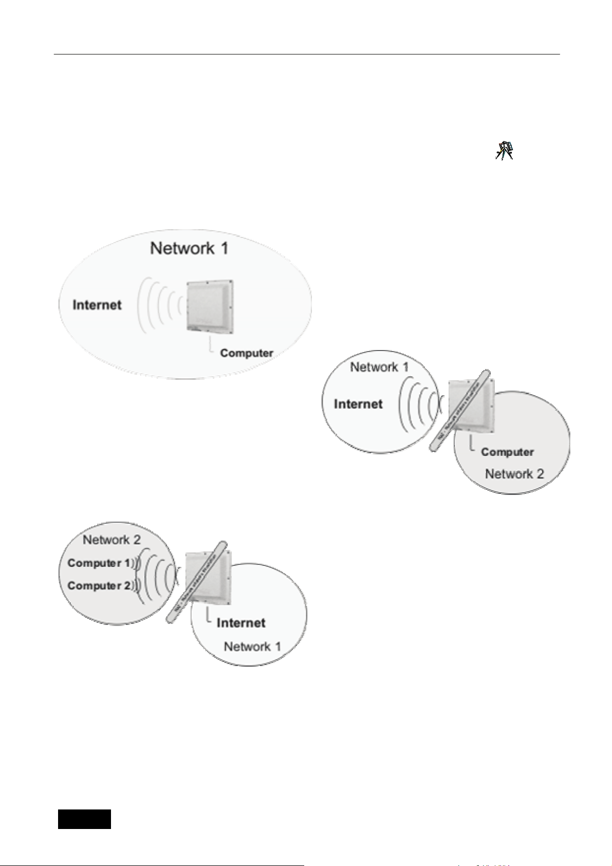
6.3 Nastavení režimu provozu 9
Prvním krokem při nastavování jednotky je volba provozního režimu z hlediska routování sítí. K této
konfigurační nabídce se dostanete pomocí menu Síť&Firewall záložka Režim sítě. Jednotka nabízí 3
operační režimy.
V defaultním nastavení je jednotka v režimu 1BRIDGE, kdy jsou obě rozhraní na stejné úrovni. Z
obou je jednotka dostupná na stejné IP adrese.
Toto nastavení je obvyklé při použití zařízení jako
přístupového bodu a v některých případech i
v režimu klientského zařízení. Veškerá nastavení
týkající se provozu překladu adres NAT nejsou
dostupná.
Režim 2 se typicky používá pro provoz klientské
jednotky. Jednotka je pak k internetu připojena pomocí
bezdrátového rozhraní. Pro připojení klientských
počítačů může být použity porty na PSW-105. Pro
počítače zákazníků je pak tato jednotka užívána jako
výchozí brána. Pro konfiguraci je jednotka dostupná na
příslušných IP adresách strany LAN a WAN. Toto
nastavení je zpravidla kombinováno s funkcí DHCP
serveru, který automaticky přiřazuje adresy jednotlivým
počítačům.
Typickým použitím režimu 3 je jednotka užitá jako
běžný bezdrátový router, například pro připojení
ADSL, či Ethernet. V tom případě je internet
přiveden kabelem do switche PSW-105 portu
označeného jako Ethernet. Klientské počítače jsou
pak připojeny bezdrátově. V tom případě je třeba
rádio nastavit do režimu přístupový bod.
6.4 Nastavení bezdrátové části
Tato multifunkční jednotka pracuje v několika operačních režimech: Přístupový bod, Stanice, Systém
WDS, přístupový bod WDS a Opakovač. Nejčastěji se jednotka GWP-207VE používá v operačním módu
stanice, pro který je určena.
Mód provozu “Přístupový bod” se užívá v případě, kdy tato jednotka slouží jako centrální bod Vaší
bezdrátové sítě, ke kterému se následně připojují další bezdrátové adaptéry v módu Stanice - Infrastruktura.
Česká verze
10
Page 29

Konfigurace bezdrátového přístupového bodu LAN
p
Operační mód “Stanice” se dále dělí na dva typy. “Stanice” se užívá v případě sítí, kde existuje
centrální přístupový bod, jak bylo popsáno výše. V případě užití operačního režimu “Ad Hoc” lze vytvořit síť
přímo mezi jednotlivými adaptéry bez účasti centrálního přístupového bodu. (Komunikace typu Peer-to-Peer)
Operační režim typu “Systém WDS” (jinak také nazývaný BRIDGE) je určen především pro
propojení dvou (“Bridge Point-to-Point”) či více (“ Bridge Point-to-Multipoint”) LAN sítí dohromady.
V případě nastavení operačního režimu Opakovač se pak jednotka chová zároveň jako přístupový
bod a zároveň jako klientský adaptér nadřazené jednotky v režimu Access Point.
Proč je režim Systém WDS/Bridge vhodnější k propojování LAN sítí?
Při užití operačních režimů Stanice (oba typy), dochází u jednotek ve shodě s WiFi standardy ke změně
hlavičky paketu na druhé úrovni – tedy k záměně MAC adresy koncového zařízení za MAC adresu jednotky.
V některých aplikacích, kdy se za jednotkou nachází více než jedno koncové zařízení, může tato záměna
síťové adresy způsobit problémy. V režimech Bridge se naproti tomu jednotka chová zcela transparentně i
na druhé úrovni a MAC adresy v hlavi
Speciálním případem režimů Systém WDS je pak typ “Přístupový bod WDS”. V tomto operačním
režimu může být jednotka využita zároveň jako přístupový bod i jako Bridge spojující LAN sítě.
čce paketu ponechává beze změny.
6.4.1 Nastavení základních parametrů
bezdrátového přenosu:
Na stránce Základní nastavení v menu Bezdrátová část definujete nejdůležitější parametry pro
rádiový přenos dat. Jejich popis naleznete v následující tabulce:
Parametr Popis
Název sítě – SSID
(Základní nastavení rádiového
modulu)
Typ provozu:
(Základní nastavení rádiového
modulu)
Operační kanál:
(Základní nastavení rádiového
modulu)
Parametr SSID (až 31 ASCII znaků) představuje klíč, na základě kterého
dochází ke spojení jednotlivých adaptérů v rámci bezdrátové sítě.
Nastavením různých síťových klíčů můžete zajistit fungování několika
bezdrátových sítí ve stejné oblasti a v rámci stejného frekvenčního
rozsahu. SSID je třeba nastavit shodně na přístupovém bodu a na všech
klientských adaptérech, které se k němu připojují. Standardně je tento
klíč nastaven na “GWP-207VEt”, doporučujeme však toto nastavení při
instalaci změnit. SSID se nastavuje v režimech provozu “Přístupový bod”,
Stanice AD HOC”, “Stanice Infrastruktura”, “Systém WDS” a “Přístupový
bod WDS”
Tato položka dává uživateli možnost definovat provozní režim jednotky
pouze pro standard 802.11b, pouze pro 802.11g či pro oba dva
standardy současně.
Tímto nastavením uživatel definuje operační kanál jednotky. Pro použití v
rámci států Evropské unie (s výjimkou Španělska) je k dispozici celkem
13 kanálů. Výběr operačního kanálu se neprovádí v režimu “Stanice –
Infrastruktura”, ve které je kanál automaticky nastaven dle Přístupového
bodu se shodným nastavení ESSID.
Překrývání operačních kanálů
Vzhledem k dělení frekvenčního pásma na 13 kanálů a vzhledem k
šířce využívaného frekvenčního pásma dochází k překrývání jednotlivých
kanálů. Proto, je-li tato možnost, nejlepších výsledků dosáhnete při
oužívání WiFi přístupových bodů tak, aby se jednotky v dané oblasti
nacházely alespoň 3 až 5 kanálů od sebe. Například využívat tedy kanály
1,7,13, kdy již k žádnému vzájemnému rušení nedochází.
10
Norma pro WiFi
(Základní nastavení rádiového
modulu)
MAC Adresa:
(Nastavení WDS/Bridge)
Česká verze
V tomto políčku vybíráte normu pro provoz rádiové části. Pro použití
v České Republice volte ETSI.
V režimech typu Bridge a WDS systém je třeba definovat MAC adresy
všech připojených bezdrátových jednotek, které systém využívá k
11
Page 30

vzájemné identifikaci členů dané Bridge či WDS struktury.
Nastavit zabezpečení:
(Nastavení WDS/Bridge)
Zobrazit statistiky:
(Nastavení WDS/Bridge)
Připojené stanice:
(Základní nastavení rádiového
modulu)
Dostupné sítě:
(Základní nastavení rádiového
modulu)
V operačních režimech typu WDS můžete využít toto tlačítko pro
nastavení šifrování přenosu z bezpečnostních důvodů.
V režimu WDS můžete pomocí tohoto tlačítka zobrazit tabulku se
statistickými informacemi o přenosech jednotlivých WDS klientů.
Stisknutím tlačítka “Zobrazit aktivní stanice” dojde k otevření okna s
přehledem aktuálně připojených klientů a přenosových parametrů těchto
stanic.
Použitím tlačítka na prohledání dostupných sítí v operačním módu
Stanice vyvoláte tabulku dostupných bezdrátových sítí. Vybráním
bezdrátové sítě a stisknutím tlačítka Připojit bude Vaše jednotka
automaticky nakonfigurována pro připojení k dané síti. V případě, že síť
využívá některý ze zabezpečovacích protokolů, je třeba samotné
zabezpečení nastavit ručně.
Konfigurace bezdrátového přístupového bodu LAN
Pro uložení změn stiskněte tlačítko “Použít” v levém rohu stránky .Nyní můžete přejít k nastavování dalších
parametrů, či začít užívat Vaši jednotku.
6.4.2 Pokročilá nastavení rádiového přenosu 11
Na této stránce lze zadat podrobněji parametry, ovlivňující bezdrátový provoz. Parametry jsou
defaultně nastaveny tak, že je není při běžném provozu třeba měnit, nicméně v zarušeném prostředí může
jejich optimalizace přinést zvýšení přenosové rychlosti či nižší chybovost přenosu.
Parametr Popis
Typ autentifikace
Úroveň fragmentace
Úroveň RTS
Toto pole nabízí tři možnosti. Při výběru možnosti „Otevřený systém“ se
do sítě může připojit jakákoliv stanice bez ohledu na šifrování. Pokud
vyberete „Sdílený klíč“, pak se lze do sítě připojit pouze jednotkou, která
má nastaven stejný sdílený klíč v nastavení zabezpečení. Hodnota
Automaticky pak kombinuje oba dva režimy.
Úroveň fragmentace určuje maximální velikost paketu při fragmentaci dat
k odeslání. Pokud nastavíte příliš nízkou hodnotu, dojde ke snížení
výkonu.
Pokud je velikost paketu menší než mezní hodnota RTS, přístupový bod
nepoužije k odeslání tohoto paketu mechanismus RTS/CTS.
Interval Beacon paketu
Linková rychlost
DTIM Perioda
Česká verze
Časový interval, ve kterém přístupový bod vysílá signál (beacon). Signál
slouží k synchronizaci bezdrátové sítě.
Přenosová rychlost určuje rychlost přenosu dat, kterou používá tento
přístupový bod. Přístupový bod používá k přenosu paketů nejvyšší
možnou vybranou rychlost přenosu.
DTIM je součást beacon paketu, která informuje jednotky v režimu
úspory energie. že bude následovat přenos dat. V případě zvýšení této
hodnoty se prodlužuje prodleva mezi stavem šetření energie a
přechodem do provozního režimu.
12
Page 31

Konfigurace bezdrátového přístupového bodu LAN
Typ preambule
Skrýt SSID
Funkce IAPP
Ochrana 802.11g
Izolace bezdrátových klientů
Vysílací výkon 802.11b
Vysílací výkon 802.11g
Vstupní zesílení
Klepnutím na tlačítko Použít v dolní části obrazovky uložte výše uvedenou konfiguraci. Nyní můžete
nakonfigurovat další části nebo začít používat přístupový bod.
Typ preambule určuje délku bloku CRC v rámci během bezdrátové
komunikace. Možnost „Krátký úvod“ je vhodná v bezdrátových sítích s
vysokým provozem. Možnost „Dlouhý úvod“ může poskytovat
spolehlivější komunikaci
Pokud zakážete funkci „Skrýt SSID“, může každá bezdrátová stanice
umístěná v oblasti pokrytí tohoto přístupového bodu snadno zjistit jeho
přítomnost. Pokud vytváříte veřejnou bezdrátovou síť, je doporučeno
povolit tuto funkci. Povolení funkce „Skrýt SSID“ může poskytovat lepší
zabezpečení.
Pokud povolíte funkci IAPP, bude přístupový bod automaticky vysílat
informace o přiřazených bezdrátových stanicích jeho sousedům. To
usnadní plynulé přecházení bezdrátové stanice mezi přístupovými body.
Pokud vaše bezdrátová síť LAN obsahuje více než jeden přístupový bod
a je třeba, aby se bezdrátové stanice pohybovaly, je doporučeno povolit
tuto funkci. Zakázání funkce „IAPP“ může poskytovat lepší zabezpečení.
Tato funkce se také nazývá Ochrana CTS. Mechanismus ochrany je
doporučeno povolit. To umožňuje snížit míru kolizí mezi bezdrátovými
stanicemi 802.11b a 802.11g Pokud je povolen režim ochrany, bude
propustnost přístupového bodu nepatrně nižší z důvodu potřeby přenosu
vysokého počtu rámců.
Tato funkce bude použita pouze v operačním režimu Přístupový bod. Po
aktivaci této funkce dojde k zablokování komunikace mezi jednotlivými
klienty v rámci přístupového bodu.
Zde je možné definovat vysílací výkon pro provoz dle standardu 802.11b,
tedy s modulací CCK. Při nastavování výkonu se vždy seznamte
s omezeními platnými v oblasti, kde je jednotka užívána. Pro použití
v ČR se držte pokynů v kapitole „Užití zařízení“
Zde je možné definovat vysílací výkon pro provoz dle standardu 802.11g,
tedy s modulací OFDM. Při nastavování výkonu se vždy seznamte
s omezeními platnými v oblasti, kde je jednotka užívána. Pro použití
v ČR se držte pokynů v kapitole „Užití zařízení“
Nastavuje úroveň zesílení předzesilovače vstupu při příjmu signálu.
Nastavením vyšších hodnot je možné zachytit i dříve nedostupné
bezdrátové sítě, nicméně dochází zároveň k nárůstu šumu v přijímaném
signálu a tedy i větší chybovosti přenosu.
6.4.3 Zabezpečení 12
Přístupový bod poskytuje všechny funkce zabezpečení bezdrátové sítě LAN, včetně WEP, IEEE
802.11x, IEEE 802.11x s WEP, WPA s předem sdíleným klíčem a WPA se servery RADIUS. Tyto funkce
zabezpečení umožňují zabránit neoprávněnému přístupu do vaší bezdrátové sítě LAN. Zkontrolujte, zda
všechny bezdrátové stanice používají stejnou funkci zabezpečení.
Kromě běžných typů šifrování je možné vždy zapnout navíc předověření pomocí Radius serveru a standardu
802.1x. Protokol IEEE 802.1x je ověřovací protokol. Každý uživatel se musí před přístupem k bezdrátové síti
LAN přihlásit k přístupovému bodu pomocí platného účtu. Ověřování provádí server RADIUS. V tomto
režimu je uživatel ověřen pouze pomocí protokolu IEEE 802.1x, během komunikace se neprovádí šifrování
dat. Protokol 802.1x bez šifrování lze použít v režimu „Přístupový bod“ a režimu „Přístupový bod WDS“ .
Poznámka: V režimu „Přístupový bod WDS“ může přístupový bod pracovat jako stanice a přístupový
bod zároveň. Nastavení zabezpečení v režimu „Přístupový bod WDS“ se vztahuje pouze na funkce
přístupového bodu.
Česká verze
13
Page 32

Konfigurace bezdrátového přístupového bodu LAN
Parametr Popis
Typ zabezpečení:
Formát WEP klíče:
WEP klíč:
Formát sdíleného klíče:
Sdílený klíč:
V této položce můžete vybrat typ zabezpečení, které bude použito. K
dispozici jsou typy WEP, WPA a WPA s podporou RADIUS serveru
Tato položka je použita pouze v případě šifrování WEP. Označuje formát,
ve kterém budou klíče zadávány. Na výběr jsou typy ASCII a
Hexadecimální tvar.
Hodnota výchozího klíče pro šifrování WEP.
V této položce vybíráte formát klíče systému WPA. Opět lze vybrat z typu
ASCII či Hexadecimální.
Klíč pro šifrování dat v systému WPA.
6.4.3.1 Šifrování WEP 13
Pro nastavení šifrovacích klíčů WEP zabezpečení slouží stránka „Šifrování WEP“. Popis jednotlivých
parametrů naleznete v následující tabulce:
Parametr Popis
Délka klíče Je možné vybrat 64bitový nebo 128bitový klíč k šifrování přenášených
dat. Delší klíč WEP poskytuje vyšší úroveň zabezpečení, ale nižší
propustnost.
Formát klíče Pro klíč WEP je možné vybrat ASCII znaky (alfanumerický formát) nebo
hexadecimální číslice (v rozsahu „A-F“, „a-f“ a „0-9“). Například:
ASCII znaky: guest
Hexadecimální číslice 12345abcde
Výchozí klíč Vyberte jeden ze čtyř klíčů pro šifrování dat. Použije se pouze klíč
Šifrovací klíč 1 – 4 Klíče WEP slouží k šifrování přenášených dat v bezdrátové síti. Vyplňte
Stisknutím tlačítka Použít v dolní části obrazovky uložte výše uvedenou konfiguraci. Nyní můžete
nakonfigurovat další části nebo začít používat přístupový bod.
vybraný v poli „Výchozí klíč“.
textové pole podle níže uvedených pravidel.
64bitový WEP: jako šifrovací klíče zadejte 10 hexadecimálních číslic (v
rozsahu „A-F“, „a-f“ a „0-9“) nebo 5 znaků ASCII.
128bitový WEP: jako šifrovací klíče zadejte 26 hexadecimálních číslic (v
rozsahu „A-F“, „a-f“ a „0-9“) nebo 10 znaků ASCII.
6.4.3.2 WPA/WPA2 14
Metoda WPA (Wi-Fi Protected Access) je pokročilý zabezpečovací standard. Pro ověřování
bezdrátových stanic a šifrování dat během komunikace je možné použít předem sdílený klíč. Provádějí se
časté změny šifrovacího klíče pomocí metod TKIP nebo CCMP(AES). Při napadení není proto snadné
prolomit šifrovací klíč. Tím se výrazně zlepšuje zabezpečení bezdrátové sítě. Šifrování s předem sdíleným
klíčem WPA lze použít v režimu „Přístupový bod“, režimu „Stanice – AD-HOC“, režimu „Stanice –
Infrastruktura“ a režimu „Přístupový bod-WDS“.
Parametr
Mód ověřování Můžete zvolit ověřování pomocí předsdíleného klíče či pomocí Radius
Formát klíče Pro předem sdílený klíč WEP je možné vybrat vstupní frázi
Popis
serveru. V tom případě bude pro ověřování využit Radius server, zadaný
v horní části obrazovky.
(alfanumerický formát) nebo hexadecimální číslice (v rozsahu „A-F“, „a-f“
a „0-9“). Například:
Vstupní fráze: iamguest
Česká verze
14
Page 33

Konfigurace bezdrátového přístupového bodu LAN
Hexadecimální číslice 12345abcde
Sdílený klíč Předem sdílený klíč slouží k ověřování a šifrování dat přenášených v
bezdrátové síti. Vyplňte textové pole podle níže uvedených pravidel.
Hex: jako předem sdílené šifrovací klíče zadejte 64 hexadecimálních
hodnot (v rozsahu „A-F“, „a-f“ a „0-9“) nebo vstupní frázi délky nejméně 8
znaků.
Stisknutím tlačítka Použít v dolní části obrazovky uložte výše uvedenou konfiguraci. Nyní můžete
nakonfigurovat další části nebo začít používat přístupový bod.
6.4.4 Filtrování MAC adres 15
Přístupový bod umožňuje filtrování MAC adres, které zabraňuje v přístupu do bezdrátové sítě
jednotkám s neznámou (nepovolenou) MAC adresou.
Parametr Popis
Nastavení filtru MAC adres
Tabulka filtrování MAC adres
Povolí nebo zakáže funkci filtrování MAC adres.
Tato tabulka obsahuje záznamy MAC adres bezdrátových stanic, kterým
chcete umožnit přístup k síti. Pole „Komentář“ obsahuje popis bezdrátové
stanice s příslušnou MAC adresou. Toto pole usnadňuje rozlišení
bezdrátových stanic.
Přidání MAC adresy do tabulky
Smazání vybraných MAC adres
Smazat vše
Klepnutím na tlačítko Použít v dolní části obrazovky uložte výše uvedenou konfiguraci. Nyní můžete
nakonfigurovat další části nebo začít používat přístupový bod.
V níže uvedené oblasti „Nová“ vyplňte pole „MAC adresa“ a „Poznámka“
bezdrátové stanice, kterou chcete přidat, a klepněte na tlačítko „Přidat“.
Bezdrátová stanice bude potom přidána do „Tabulky filtrování MAC
adres“.
Pokud chcete některou MAC adresu odebrat z „Tabulky filtrování MAC
adres“, vyberte v tabulce adresy, které chcete odebrat a klepněte na
tlačítko „Smazat vybrané“. Chcete-li odebrat z tabulky všechny MAC
adresy, klepněte na tlačítko „Odstranit vše“.
Klepnutím na tlačítko „Smazat vše“ je možné vymazat celou tabulku.
6.5 Nastavení IP
V bodě hlavní nabídky, označeném jako ethernetová část, lze definovat veškeré parametry spojené
s používáním protokolu TCP/IP.
6.5.1 Nastavení TCP/IP portu LAN 16
Na této stránce můžete nastavit parametry protokolu TCP/IP týkající se rozhraní LAN, tedy rozhraní,
které v operačním režimu ROUTER směřuje do lokální sítě. Toto nastavení bude také použito v operačním
režimu BRIDGE. Kromě standardních TCP/IP parametrů, jako je IP adresa, síťová maska a výchozí brána
se zde definují také parametry, spojené s využíváním služeb DHCP.
DHCP může být používáno v několika provozních režimech:
DHCP Klient: v tomto režimu zařízení očekává přidělení vlastních TCP/IP parametrů nadřazeným
DHCP serverem.
DHCP Server: při využití tohoto operačního režimu je naopak jednotka sama poskytovatelem
informací o TCP/IP nastavení pro další klienty. Jsou předávány parametry IP adresa, maska a brána.
V položce „Rozsah adres pro DHCP“ lze definovat, jaké adresy budou klientům přiřazovány. Po stisknutí
tlačítka „Zobrazit klienty“ bude zobrazen seznam aktuálně přidělených adres.
DHCP vypnuto: v tomto případě nejsou služby protokolu DHCP využívány.
Česká verze
15
Page 34

Konfigurace bezdrátového přístupového bodu LAN
Další možností nastavení je pak zapnutí směrovacího protokolu Spanning Tree, definovaného
standardem 802.1d. Klonování MAC adresy je funkce určená pro případ, kdy je třeba změnit konfiguraci HW
adresy rozhraní LAN.
6.5.2 Nastavení TCP/IP portu WAN
Na této stránce definujete nastavení bezdrátového rozhraní směřovaného do Internetu. Pokud
jednotku užíváte v režimu BRIDGE, tato nastavení nebudou použita. Tato stránka je dynamická, její vzhled
se mění dle aktuálně vybraného typu připojení do internetu. O výběru vhodného typu připojení rozhoduje
způsob použití jednotky, případně Váš poskytovatel konektivity. Těchto typů je celkem 5:
6.5.2.1 Statická IP adresa
Režim, při kterém je IP adresa manuálně do zařízení zadána. Kromě IP adresy, brány a masky se
zadávají ještě tři názvové servery DNS, které se navzájem při provozu zálohují. Poslední zadávanou
položkou je pak možná definice MAC adresy rozhraní WAN.
6.5.2.2 DHCP Klient
Při použití nastavení DHCP klient definujete pouze způsob přidělení informace o DNS serveru,
případně MAC adresu WAN portu. Ostatní parametry TCP/IP jsou automaticky přiděleny nadřazeným DHCP
serverem.
6.5.2.3 PPPoE
Nastavení pro PPPoE (Point-To-Point Protocol Over Ethernet) je často využíváno poskytovateli
připojení k internetu. Jedná se o jednoduchý způsob ověřovaného spojení zabezpečeného jménem a
heslem, které je třeba při konfiguraci zadat. Dále se definuje typ spojení (Trvalé, Na vyžádání, Ručně
navazované), doba, po které dojde k automatickému odpojení a maximální velikost odeslaného paketu. Opět
je zde možnost manuální definice MAC adresy rozhraní.
6.5.2.4 PPTP
Nastavení PPTP je určeno k automatickému připojení k Virtuální Privátní síti. Spojení je definováno
IP adresou serveru, uživatelským jménem a heslem. Opět zůstává možnost definice MTU, DNS serverů a
MAC adresy rozhraní, dále pak typ šifrování MPPE či MSCHAP. Pro získání parametrů pro připojení
kontaktujte správce VPN sítě.
6.5.2.5 PPTP+DHCP
Stejně jako v předchozím případě je tato volba určena k připojení k VPN síti s tím rozdílem, že
lokální IP adresa je získána ze serveru DHCP, umístěného v dané VPN.
6.6 Brána a směrování
17
Na stránce Brána a směrování definujete statické položky směrovací tabulky pro zajištění správné
funkce jednotky v režimu router. Pro nastavení těchto parametrů je třeba znát strukturu sítě, ve které je
jednotka instalována. Položka „Výchozí brána“ (Default gateway) určuje hraniční router, na který budou
odesílány veškeré pakety, jejichž směrování není definováno automaticky ani ručně vytvořeným směrovacím
(routovacím) pravidlem.
Česká verze
16
Page 35

Konfigurace bezdrátového přístupového bodu LAN
6.7 Síť a Firewall
Kromě základního nastavení režimu sítě, popsaného v kapitole 3.3, naleznete pod záložkou „Síť a Firewall“
následují možnosti.
6.7.1 Blokování IP/MAC adres, Blokování portů 18
Vzhledem ke shodnému zaměření konfiguračních možností záložek „Blokování IP adres“ a
„Blokování MAC adres“ zde uvádíme obrázek pouze pro první z nich.
Položky v tabulce Blokování IP adres jsou použity k omezení průchodu některých paketů směřujících
z vnitřní sítě, což omezí možnost zneužití Vašeho internetového připojení stejně jako nechtěný únik
informací z některých stanic ve Vaší síti.
Položky v tabulce „Blokování MAC adres“ umožňují zabránit odesílání dat z Vaší sítě definicí práv
vázaných na HW adresy jednotlivých zařízení.
Položky v tabulce „Blokování portů“ umožňují omezit rozsah průchozích TCP/IP či UDP portů skrz
jednotku. Tímto nastavením lze například omezit dostupnost některých služeb poskytovaných z vnější sítě.
Pro snadnější orientaci ve vytvořených tabulkách je možno ke každé zadané položce vytvořit poznámku
s popisem daného pravidla.
6.7.2 Směrování portů 19
Položky v této tabulce řídí přesměrování příchozích portů na vnějším rozhraní brány na libovolnou IP
adresu vnitřní sítě. Tím můžete vybrané počítače ve vnitřní síti použít jako servery, či mít přístup k jejich
vzdálené správě. Symbol "S" znamená dopřednou změnu zdrojové adresy, která je nezbytná pro některé
programy. Symbol "C" označuje změnu cílového portu (druhá hodnota se stává číslem cílového portu).
6.7.3 Nastavení DMZ (Demilitarizovaná zóna)
Použitím funkce Demilitarizovaná zóna můžete jeden počítač z Vaší sítě zpřístupnit přímo z
internetu.Na počítač budou směrovány veškeré služby kromě služeb poskytovaných samotným routerem.
6.8 Služby
V záložce hlavního menu „Ovládání“ naleznete funkce spojené s vlastním provozem jednotky,
funkce pro aktualizaci softwarového vybavení, změny přístupových hesel atd.
6.8.1 Limit rychlosti 20
Na této stránce lze definovat rychlostní omezení, platné pro celou jednotku. Směr pro Upload a
Download je vždy brán z pohledu zákazníka.
Pro pokročilé uživatele: Pokud je jednotka v operačním režimu BRIDGE, pak se Uploadem rozumí omezení
vysílání ethernetového rozhraní a Downloadem omezení vysílání rozhraní bezdrátového. V operačním
režimu ROUTER se pak úlohy jednotlivých rozhraní převrací.
6.8.2 Nastavení DDNS 21
Dynamické DNS je služba, která umožňuje zaregistrovat platnou doménu pro měnící se
(dynamickou) IP adresu. Jednotka podporuje 2 poskytovatele této služby, společnosti DynDNS a TZO. U
společnosti TZO je možné zdarma získat 30-ti denní zkušební verzi této služby. Více informací naleznete na
www.tzo.com.
6.8.3 Časový server 22
Na záložce „Časový server“ je možné definovat konfiguraci pro synchronizaci s časovým serverem NTP.
Server lze buď vybrat z připravovaného seznamu, nebo definovat vlastní.
Česká verze
17
Page 36

Konfigurace bezdrátového přístupového bodu LAN
6.8.4 Watchdog/Restart 23
Z provozních důvodů může být někdy vhodné jednotku v automatických intervalech restartovat.
V tom případě využijte nastavení pod záložkou „Watchdog/Restart“. Zde je možné tuto funkci zapnout, ale i
definovat čas, po kterém bude k automatickému restartu docházet.
Další možností je pak restartování jednotky v případě ztráty spojení s danou IP adresou. Je třeba
definovat interval testu a dále pak jednu či dvě IP adresy. Při testu je vždy kontrolována IP adresa 1, jestliže
při testu vykazuje větší ztráty než 20%, přejde se k testování IP adresy 2. Pokud test IP adresy projde, pak
k testování IP 2 nedochází. V případě, že ani IP adresa 2 není dostupná, dochází automaticky k restartu
jednotky.
6.8.5 Test sítě 24
Záložka Test sítě obsahuje běžné nástroje pro testování sítí na protokolu TCP/IP. Jsou dostupné
nástroje Ping, Arping a Traceroute včetně příslušných parametrů. Výsledek testování se zobrazuje ve
spodním okně. Po zadání parametrů použijte tlačítko ODESLAT.
Česká verze
18
Page 37

Konfigurace bezdrátového přístupového bodu LAN
Chapter 7 Správa
7.1.1 Změna hesla 25
Záložka „Změna hesla“, jak již název napovídá, slouží ke změně přístupových hesel k ovládání
jednotky. Parametr „Vypnout Superuživatele“ zablokuje možnost připojit se do jednotky pomocí
neveřejného hesla zadaného výrobcem.
7.1.2 Uložení/Obnovení konfigurace 26
Obrazovka Uložení/Obnovení konfigurace umožňuje uložit aktuální nastavení konfigurace
přístupového bodu. Uložení konfigurace poskytuje další ochranu a vhodný způsob, pokud dojde k
problémům s přístupovým bodem a je nutné obnovit výchozí nastavení od výrobce. Pokud uložíte nastavení
konfigurace, můžete archivovanou konfiguraci znovu načíst do přístupového bodu pomocí tlačítka „Obnovit“.
V případě vážných problémů můžete použít možnost Obnovit výchozí nastavení od výrobce. Tato možnost
nastaví všechny konfigurační hodnoty na jejich výchozí hodnotu při zakoupení přístupového bodu.
7.1.3 Aktualizace 27
Na stránce „Aktualizace“ lze provést aktualizaci software, užívaného jednotkou v případě, že se
jednotka nechová dle předpokladů, nebo z důvodu vydání nové verze řídícího software. Po vybrání
souboru s aktualizací použijte tlačítko „Nahrát“. Samotná aktualizace může trvat až 180 sekund – po tuto
dobu nepřerušujte napájení jednotky. Aktualizaci doporučujeme provádět výhradně pomocí připojení
metalickým kabelem.
V případě, že jste k jednotce připojeni linkou o nižší datové propustnosti, zatrhněte záložku „pomalý
upload“. Tímto se prodlouží doba čekání na dokončení přenosu.
7.1.4 Rozhraní www 28
Na této stránce lze konfigurovat parametry rozhraní pro zprávu jednotky a jeho dostupnost
z jednotlivých portů. Dále lze nadefinovat TCP/IP port pro přístup, což je vhodné například v případě kdy
je třeba uvolnit port 80 z důvodu provozu www serveru v DMZ, nebo pomocí směrování portů.
7.2 Restart
Pokud jednotka přestane správně reagovat, je možné provést vzdálený restart operačního systému.
Nastavení nebude změněno. Reset je možné provést klepnutím na tlačítko Restart pod hlavní nabídkou.
Provedení restartu je okamžité, bez potvrzovacího dialogu.
Česká verze
19
Page 38

Introduction
Chapter 8 Odstraňování potíží
Tato kapitola poskytuje řešení problémů, ke kterým může docházet při instalaci a provozu přístupového
bodu.
11. Jak je možné ručně zjistit IP adresu a MAC adresu počítače?
1) V systému Windows spusťte program Příkazový řádek.
2) Zadejte příkaz Ipconfig /all a stiskněte klávesu Enter
y IP adresa počítače je označena názvem Adresa IP.
y MAC adresa počítače je označena názvem Fyzická adresa.
12. Co je AD-HOC?
Bezdrátová síť LAN typu AD-HOC je skupina počítačů s adaptéry WLAN, propojených nezávislou
bezdrátovou sítí LAN.
13. Co je Infrastruktura?
Konfigurace Infrastruktury označuje společnou bezdrátovou síť LAN a pevnou síť LAN (propojenou
kabelem).
14. Co je BSS ID?
Skupina bezdrátových stanic a přístupový bod vytváří skupinu BSS (Basic Service Set). Počítače ve
skupině BSS musí mít nastavenu stejnou hodnotu BSS ID.
15. Co je ESSID?
Konfigurace Infrastruktury může podporovat možnosti roamingu pro mobilní práci. Více skupin BSS
ůže být nakonfigurováno jako ESS (Extended Service Set). Uživatelé v rámci ESS mohou volně
m
cestovat mezi BSS, přičemž je zachováno trvalé připojení ke stanicím bezdrátové sítě a přístupovým
bodům bezdrátové sítě LAN.
16. Mohou být data při bezdrátovém přenosu odposlouchávána?
Síť WLAN poskytuje dva způsoby zabezpečení. Na straně hardwaru prostřednictvím technologie DSSS
(Direct Sequence Spread Spectrum), která zabezpečuje přenášená data pomocí kódování. Na straně
softwaru síť WLAN nabízí funkci šifrování (WEP, WPA, WPA2), která zlepšuje zabezpečení a kontrolu
přístupu.
17. Co je WEP?
WEP (Wired Equivalent Privacy) označuje mechanismus zabezpečení dat založený na algoritmu
64(40)bitového sdíleného klíče.
18. Co je WPA?
WPA je zkratka Wi-Fi Protected Access. Jde o zabezpečovací protokol bezdrátových sítí 802.11. WPA
poskytuje ochranu dat pomocí šifrování a používá řízení přístupu a ověřování uživatelů.
19. Co je WPA2?
WPA2 poskytuje proti WPA silnější mechanismus šifrování pomocí standardu AES (Advanced
Encryption Standard).
20. Co je MAC adresa?
MAC (Media Access Control) adresa je jedinečné číslo přiřazené výrobcem každému zařízení sítě
Ethernet, nap
číslo je ve všech běžných případech trvalé. Na rozdíl od IP adres, které se mohou měnit při každém
přihlášení počítače do sítě, MAC adresa zařízení zůstává stejná a je důležitá pro identifikaci v síti.
říklad síťovému adaptéru, a umožňuje identifikovat zařízení na hardwarové úrovni. Toto
Deutsche Version
1
Page 39

Introduction
Straight
C
o
Multifunktionszugriffspunkt
r
e
GWP-106VE
IEEE 802.11b/g
54Mbps
Deutsche Version
Anwenderhandbuch
2
Page 40

Introduction
Inhalt
Kapitel 1 Einleitung..............................................................................................................................................4
1.1 Packungsinhalt.............................................................................................................................................4
1.2 Funktion der Einheit .................................................................................................................................... 4
1.3 Spezifikation ................................................................................................................................................ 4
1.4 Beschreibung und Installation der Einheit ................................................................................................... 5
1.4.1 Außenteil - ODU .......................................................................................................................... 4
1.4.2 Innenteil – IDU.............................................................................................................................4
Kapitel 2 Konfiguration der Einheit ................................................................................................................... 8
2.1 Vorbereitung der Konfiguration................................................................................................................... 8
2.1.1 Einstellung Ihres PCs.................................................................................................................... 7
2.2 Statistiken ............................................................................................................................................ 8
2.2.1 Zustand der Einheit ...................................................................................................................9
2.2.2 Verfügbare Netze.......................................................................................................................... 8
2.2.3 Daten ............................................................................................................................................ 8
2.2.4 Drahtlose Einschlüsse...................................................................................................................8
2.2.5 DHCP-Klienten ............................................................................................................................ 8
2.2.6 WDS-Anschluss ........................................................................................................................... 8
2.2.7 Richtungstabelle ........................................................................................................................... 8
2.2.8 ARP-Tabelle.................................................................................................................................8
2.3 Betriebsmoduseinstellung............................................................................................................................9
2.4 Einstellung des drahtlosen Teils ................................................................................................................ 10
2.4.1 Einstellung der Grundparameter der drahtlosen Übertragung.......................................... 10
2.4.2 Fortgeschrittene Einstellung der Funkübertragung.............................................................11
2.4.3 Absicherung..............................................................................................................................12
2.4.4 Filtrierung von MAC-Adressen............................................................................................... 14
2.5 IP-Einstellung ............................................................................................................................................14
2.5.1 TCP/IP-Einstellung des LAN-Ports .......................................................................................14
2.5.2 TCP/IP-Einstellung des WAN-Ports......................................................................................15
2.5.3 Tor und Ausrichtung................................................................................................................... 15
2.6 Netz und Firewall....................................................................................................................................... 16
2.6.1 Blockierung der IP/MAC-Adressen, Blockierung der Porte ......................................................16
2.6.2 Ausrichtung der Porte.................................................................................................................16
2.6.3 DMZ-Einstellung (entmilitarisierte Zone)..............................................................................17
2.7 Dienste ....................................................................................................................................................... 17
2.7.1 Geschwindigkeitslimit................................................................................................................16
2.7.2 DDNS-Einstellung....................................................................................................................16
2.7.3 Zeitserver .................................................................................................................................. 17
2.7.4 Watchdog/Restart .................................................................................................................... 17
2.7.5 Netztest .....................................................................................................................................17
2.8 Verwaltung ................................................................................................................................................ 19
2.8.1 Passwortänderung................................................................................................................... 18
2.8.2 Einspeicherung/Wiederherstellung der Konfiguration........................................................ 18
2.8.3 Aktualisierung........................................................................................................................... 18
2.8.4 Schnittstelle www.....................................................................................................................18
2.9 Restart........................................................................................................................................................ 18
Kapitel 3 Behebung von Störungen....................................................................................................................1
Deutsche Version
3
Page 41

Introduction
Chapter 9 Einleitung
Wir bedanken uns für den Einkauf der drahtlosen Klienteneinheit GWP-207VE. Es handelt sich um
eine Einheit für den Aufbau von Netzen gemäß dem Standard 802.11b oder 802.11g. Drahtlose Netze sind
durch Zugriffspunkte (Einheit in der Betriebsart “Access Point”) und Klienteneinrichtungen (Einheit in der
Betriebsart Infrastructure) gebildet. Für die Durchschaltung von mehreren Computern ohne Zutrittspunkt
kann die AD-HOC-Einstellung, für den Aufbau der Punkt-Punkt-Verbindung dann die Betriebsart
WDS/Bridge, angewandt werden.
Diese Einheit fördert die Sicherheitssysteme WEP, WPA, ESSID und den Filter der MAC-Adressen
für die Sicherstellung der Sicherheit des drahtlosen Netzes. Dank diesen Sicherheitsstandards können Sie
den unautorisierten Zugriff in Ihr drahtloses Netz vermeiden.
Diese Einheit ist mit einer integrierten Paneelantenne mit einem Gewinn von 14 dB ausgerüstet. Die
Einrichtung ermöglicht mittels der www-Schnittstelle die Steuerung der gesamten ausgestrahlten Leistung,
also der Leistung, die den Gewinn der eigentlichen Antenne einbezieht.
Die Einheit bietet eine sehr einfache Betätigung mittels eines beliebigen Web-Browsers, die in
mehreren Sprachen lokalisiert ist. Setzen Sie sich bitte für das aktuelle Verzeichnis der
Sprachmodifikationen der Anwenderschnittstelle mit Ihrem Lieferanten in Verbindung, gegebenenfalls Sie
finden es auch auf den Web-Seiten des Herstellers www.straightcore.net.
Die Firmware (das Steuerprogramm der Einheit) ist mit auf die Anwendung in ausgedehnten
drahtlosen Netzen gesetzten Akzenten entwickelt. Das Gehäuse der Einheit ist für die Verwendung
außerhalb des Gebäudes mit dem ausreichenden Schutz gegen herabfließendes Wasser und weitere
Witterungseinflüsse entworfen. Zwecks der einfachen Einstellung ist es möglich, an die Einheit den GWPHDF-Peiler anzuschließen, deren Beschreibung und Anwendung in diesem Handbuch zu finden ist.
¨
Anmerkung: Dieses Handbuch ist für die Version Firmware 1.0.6. geschrieben. Bei den neueren Firmwaren
können Funktionen auftauchen, die in dieser Handbuchversion nicht berücksichtigt sind.
Die Abbildungen sind in der Farbanlage zum Schluss dieses Handbuchs zu finden. Die auf das
jeweilige Kapitel sich beziehende Abbildungsnummer befindet sich jeweils neben dem Symbol.
9.1 Packungsinhalt
Die Packung der Einheit enthält folgende Teile:
y Ein schnelles Installationshandbuch
y Ein Zugriffspunkt
y Ein Versorgungsadapter
y Ein Switch PSW-105 mit dem POE-System
9.2 Funktion der Einheit
y Kompatibel mit der Spezifikation IEEE 802.11b/g (DSSS) 2.4GHz.
y Wasserdichte Ausführung mit integrierter Antenne 14 dB
y Versorgungssystem über das Ethernet PoE
y Hohe Übertragungsgeschwindigkeit bis 54Mbit/sec.
y Einfache Integration ins bestehende LAN-Netz.
y Automatische Reduzierung der Zugriffgeschwindigkeit bei gestörter Umgebung.
y Kryptografische Funktionen 64/128-bit WEP und WPA für die Sicherstellung der drahtlosen
Übertragung.
y Integrierter DHCP-Server für die automatische Zuteilung der IP-Adressen.
y Betätigung mittels des www-Browsers.
9.3 Spezifikation
y Standards: IEEE 802.11b/g (drahtloser Teil), IEEE 802.3 (Lan-Teil)
Deutsche Version
4
Page 42

y Übertragungsgeschwindigkeiten: 54/48/36/24/18/12/11/9/6/5.5/2/1Mbit/sec mit automatischer
Senkung in gestörter Umgebung
y Sicherheit: 64/128-bit WEP- und WPA- Übertragungskryptografie
y Frequenzbereich: 2.400~2.4835GHz (ISM-Band)
y Modulation:
802.11b - CCK@11/5.5Mbps, DQPSK@2Mbps a DBPSK@1Mbps
802.11g – BPSK,SPSK,16QAM,64QAM
y Drahtlose Technologie: DSSS für 802.11b, OFDM für 802.11g
y Antenne: Externer trennbarer Dipol 2dB (Steckverbinder RP-SMA)
y Netzsteckverbinder:
ODU-10/100Mbps RJ-45 x 2, GWP-HDF Port (USB Connector) x1
IDU – 5xRJ45 (PoE standardmäßig auf dem Port 1, optional 2,3,4)
y Versorgung: 12V DC
y Hochfrequenzleistung: max. 19.8 dBmW
y LED-Dioden:
ODU - Versorgung, Link (auf Steckverbindern RJ-45)
IDU - Versorgung, 4x LAN Linie/Aktivität/PoE-System, 1x LAN Linie/Aktivität
y Temperaturbereich:
Betrieb: -35°C~65°C
Einlagerung: -35°C~70°C
y Feuchtigkeit: 10-90% (nichtkondensierend)
y Zertifikation: FCC, CE
Introduction
9.4 Beschreibung und Installation der Einheit
9.4.1 Außenteil - ODU
Ein für die Anbringung an den Installationsmast bestimmter Einheitsteil. Im Vorderteil ist die integrierte
Antenne 12 dB enthalten.
9.4.1.1 Ethernet/POE Port
Im Unterteil der Freilufteinheit finden Sie den wasserdichten Teil, der mit einem Kunststoffverdeck
abgedeckt ist. In diesem Teil befinden sich der Port für den Steckverbinder RJ-45 und die Reset-Taste. Für
die Durchschaltung der Einheit mit dem internen Teil ist jeweils das vollbestückte abgeschirmte Kabel STP
Kategorie 5,5e oder 6 anzuwenden. Bei der Anwendung eines nichtabgeschirmten Kabels kann es durch
den Einfluss der statischen Entladung zur Beschädigung der Einheit oder des angeschlossenen Computers
kommen. Achten Sie nach dem Einstecken des Steckverbinders auf die korrekte Installation des
wasserbeständigen Verdecks und dessen Befestigung mit der beigefügten Schraube.
Befestigen Sie die Einheit auf den Mast mittels der Halterung und der Gabel, die Sie im Zubehör finden.
Wenn Sie die Einheit auf die Halterung so befestigen, dass die LED-Dioden auf der Vorderseite oben sind,
ist die Einheit in vertikaler Polarisierung. Für die Montage in horizontaler Polarisierung ist die Halterung um
90 Grad zu drehen, sodass das Ethernetkabel durch die Einpresstiefe im Verdeck gegen das herabfließende
Wasser geschützt ist. Verbinden Sie dann mit der mittigen Schraube die Kunststoffgabel und ziehen Sie die
Schraube nach der Befestigung der gesamten Einheit auf den Mast so fest, dass die Neigung der Einheit der
Richtung der Platzierung des Sendepunkts bestens entspricht, an den der GWP-106GE anzuschließen ist.
9.4.1.2 Reset-Taste
Die Einheit ist mit der zu deren Restart oder zur Rücksetzung auf die werkseitige Einstellung dienenden
Taste ausgestattet. Diese Taste finden Sie rechts vom Steckverbinder RJ-45. Verwenden Sie für die
Betätigung der Taste einen Kuli oder ein anderes geeignetes Instrument. Die Anwendung sieht
folgendermaßen aus:
• Durch eine kürzer als 4 Sekunden dauernde Betätigung kommt es zum Restart des
Zugriffspunkts. Die Konfigurationsparameter bleiben in diesem Fall bestehen.
• Im Falle des Passwort- oder IP-Adressenverlustes ist es möglich, den Kontakt für eine länger als
4 Sekunden betragende Dauer zu schalten bzw. zu betätigen. In diesem Fall kommt es zur
Deutsche Version
5
Page 43

Introduction
Wiederherstellung der werkseitigen Einstellung und zum Restart des Zugriffspunkts an der
Ausgangsadresse 192.168.1.1 und sie wird weder durch einen Anwendernamen noch ein
Passwort geschützt.
9.4.2 Innenteil – IDU
Der Innenteil der Einheit wird in zwei Ausführungen geliefert, die folgenden Beschreibungen
entsprechen:
9.4.2.1 Standardmäßiger Power Injector
In der Grundausführung wird die Einheit mit dem standardmäßigen Injektor ohne integrierten Switch
geliefert. Seine Schaltung ist einfach. In den als LAN gekennzeichneten Port schließen Sie das
Ethernetkabel von Ihrem PC oder Switch an. Der POE-Port ist zum Anschluss des zu der eigentlichen ODUEinheit führenden Kabels bestimmt. In den als DC gekennzeichneten Port schließen Sie den mitgelieferten
Netzadapter an – damit ist die Installation abgeschlossen. Vorsicht, beim fehlerhaften Einstecken der
Kabel in die einzelnen Porte kann es zur schwerwiegenden Beschädigung Ihres Switches oder
Computers kommen. Deshalb empfehlen wir, für diesen Anschluss das Kabel Cat. 3 4 oder 5 zu
verwenden, und zwar mit bloß folgenden geschalteten Kontakten: 1,2,3 und 6. In diesem Fall droht keine
Beschädigung, denn das POE-System die Übertragung auf den Kontakten 4/5 und 7/8 ausnutzt, wie es auf
der Oberseite des POE-Injektors schematisch dargestellt ist.
Zur Montage des Injektors an die Wand ist es möglich, Seitenhalterungen und kleine Schrauben zu
verwenden, die allerdings keinen Bestandteil der Lieferung bilden. Der Abstand der Montageöffnungen
beträgt 68 mm.
9.4.2.2 PSW-105/205
Als optionales Zubehör kann zur Einheit GWP-106VE der Injektor PSW-105/205 mit integriertem 4Port-Switch geliefert werden. Diese Variante ist mit LED-Dioden für die Funktionskontrolle versehen. Die
Beschreibung des Zustands und der Funktion der einzelnen LED-Dioden finden Sie in folgender Tabelle:
LED Farbe Zustand Beschreibung
Power Orange
Grün
1-4/POE
5 Grün
Orange
Rot
9.4.2.2.1. POE-System
Der IDU PSW-105 ist mit dem POE-System (Power-Over-Ethernet) ausgestattet. In der standardmäßigen
Konfiguration ist das POE nur auf dem Port Nr. 1 aktiv, der zur Versorgung der Einheit bestimmt ist. In
Sonderfällen kann man durch die Durchschaltung des Umschalters J1 auf der Switch-Platte auch die
Versorgung auf den Porten 2-4 einschalten und damit durch den PSW-105 Switch bis 4 externe Rinheiten
speisen (in diesem Fall ist die mitgelieferte Netzquelle gegen die 12V/2A-Quelle zu tauschen). Eine weitere
Ausnutzungsmöglichkeit dieser Betriebsart ist zum Beispiel die Installation eines Switches beim PC mit
aktivem POE-Port 1 und die Versorgung eines Fernswitches in der Betriebsart von 4 POE-Porten mittels
des POE-Systems. Die restlichen Porte können dann zum Anschluss von 3 externen Einheiten GWP207VE nutzen.
Schließen Sie für die schnelle Feststellung der Konfiguration PSW-105 nur die Versorgungsspannung an.
Porte, auf denen das POE-System aktiv ist, sind durch die dauerleuchtende LED-Diode gekennzeichnet.
leuchtet Die Versorgung der Einheit ist angeschlossen.
leuchtet nicht Keine Versorgung vorhanden.
leuchtet nicht Die Linie ist abgeschaltet, POE inaktiv
Rot Die Linie ist abgeschaltet, POE für den gegebenen Port aktiv
Orange leuchtet Die Linie ist zugeschaltet, POE für den gegebenen Port aktiv
Orange blinkt Die Linie ist zugeschaltet, POE aktiv, Datenübertragung
Grün leuchtet Die Linie ist zugeschaltet, POE inaktiv
Grün blinkt Die Linie ist zugeschaltet, POE inaktiv, Datenübertragung
leuchtet
blinkt Die Linie sendet oder empfängt Daten.
leuchtet nicht Die Linie ist abgeschaltet.
Die Linie ist angeschlossen.
Deutsche Version
6
Page 44

Introduction
9.4.2.2.2. IDU-Versorgung/Schaltung von mehreren Einheiten
Der Steckverbinder DC-12V dient für den Anschluss der Versorgungsspannung. Es wird standardmäßig die
Quelle 12V/500mA mitgeliefert, die für den Betrieb des Switches und einer Einheit auf dem Kabel bis zur
15m-Länge ausreichend ist. Beim Betrieb auf einem längeren Kabel kann man für die Versorgung eine
stabilisierte Quelle bis max. 18V verwenden. Durch die Erhöhung der Eingangsspannung kann der
Stabilbetrieb bis auf 70m Ethernetleitung sichergestellt werden. Beim Anschluss von mehreren Einheiten
an einen PSW-105 ist im Gegenteil der Eingangsstrom zu erhöhen. Für jede angeschlossene Einheit ist mit
Strom von 400mA und für jeden fernversorgten Switch mit Strom von 100mA zu rechen.
9.4.2.2.3. Ethernet-Porte 1/5
Der Steckverbinder für den Anschluss der Einrichtung ins übliche LAN-Computernetz mit dem Kabel
Cat.5,5E oder Cat.6. Vorsicht, an die Porte mit dem aktiven POE-System sind lediglich externe StraightCoreEinheiten anzuschließen. Der Anschluss einer anderen Einrichtung kann sowohl zur Beschädigung des
Switches als auch der angeschlossenen Einrichtung führen.
.
Deutsche Version
7
Page 45

Konfiguration des drahtlosen Zugriffspunkts LAN
Chapter 10 Konfiguration der Einheit
10.1 Vorbereitung der Konfiguration
Diese Einheit bietet eine einfache Betätigung mittels des www-Browsers. Für den Zugriff auf die
Konfiguration sind unten beschriebene Schritte zu befolgen.
10.1.1 Einstellung Ihres PCs
Vergewissern Sie sich, dass Ihr Computer im identischen IP-Bereich wie die drahtlose Einheit
eingestellt ist. Die werkseitige TCP/IP-Einstellung der Einheit sieht folgendermaßen aus:
Die Ausgangs-IP-Adresse: 192.168.1.1
Ausgangsmaske: 255.255.255.0
Konfiguration der TCP/IP-Parameter Ihres PCs.
1a) Windows 95/98/Me
17. Drücken Sie die Taste Start und wählen Sie das Lesezeichen Einstellung, dann die
Systemsteuerung.
18. Klicken Sie die Ikone Netzanschluss an.
19. Überprüfen Sie die abgebildeten Positionen. Sollte das TCP/IP-Protokoll nicht installiert
werden, drücken Sie die Taste Hinzufügen. Falls das TCP/IP bereits installiert ist, treten Sie
an den Schritt 6 heran.
20. Im Dialog Typ des Netzbestandteils wählen Sie das Protokoll und drücken Sie Hinzufügen.
21. Im Fenster Typ des Netzbestandteils wählen Sie das TCP/IP und drücken Sie erneut
Hinzufügen. Für die Vollendung der Installation können Sie die Installations-CD des
Operationssystems brauchen.
22. Reihen Sie sich nach der Installation des TCP/IP-Protokolls erneut ins Verzeichnis der
Netzbestandteile ein, markieren Sie das TCP/IP-Protokoll und drücken Sie die Taste
Eigenschaften.
23. Überprüfen Sie alle Tabellen und füllen Sie sich gemäß folgenden Parametern aus:
• Bindungen: Markieren Sie Klient des Netzes Microsoft und Teilung von Dateien und
Druckereien.
• Tor: Alle Fenster bzw. Felder bleiben leer.
• DNS-Konfiguration: Wählen Sie keine DNS anwenden.
• WINS: Wählen Sie kein WINS anwenden.
• IP-Adresse: Wählen Sie IP-Adresse eingeben. Geben Sie die IP-Adresse und die
Maske dem folgenden Beispiel gemäß ein:
9 IP-Adresse: 192.168.1.3 (jegliche IP-Adresse im Bereich
192.168.1.2~192.168.1.254 ist möglich, 192.168.1.1 nicht einstellen!)
9 Maske des Netzes: 255.255.255.0
24. Starten Sie den Computer neu. Nach dem Restart wird der Computer über die von Ihnen
eingegebene IP-Adresse verfügen.
1b) Windows XP
1: Drücken Sie die Taste Start und wählen Sie die Systemsteuerung, dann klicken Sie die
Netzanschlüsse an. Es erscheint das Fenster Netzanschlüsse.
2: Klicken Sie die Ikone Anschluss an das Ortsnetz an.
3: Wählen Sie im folgenden Fenster aus dem Verzeichnis das TCP/IP und drücken Sie die Taste
Eigenschaften.
4: Im geöffneten Fenster Protokoll des Netzes Internet (TCP/IP) – Eigenschaften sind folgende
Angaben auszufüllen:
IP-Adresse: 192.168.1.2
Maske des Unternetzes: 255.255.255.0
Deutsche Version
8
Page 46
Konfiguration des drahtlosen Zugriffspunkts LAN
5: Drücken Sie die OK-Taste. Ihr PC ist nun für den Anschluss an die Einheit eingestellt.
Geben Sie die IP-Adresse der Einheit 192.168.1.1 in Ihren www-Browser für den Zugriff auf die
Konfiguration ein. In der Ausgangskonfiguration wird die Einheit weder durch das Passwort noch durch den
Namen geschützt. Sie können nun die GWP-106VE-Einheit für den Anschluss an den Zugriffspunkt
konfigurieren.
10.2 Statistiken 1
In der Abbildung 1 in der Bildanlage sehen Sie die einleitende Seite nach dem Eingang in die
Steuereinheit. An die einzelnen Konfigurationsparameter treten Sie mittels des Zweiers von
Angeboten heran. Im linken Oberteil unter dem Logo des Herstellers befindet sich das primäre
Angebot mit den Hauptpositionen. Über dem eigentlichen Bildschirm ist dann das dynamische
Angebot platziert. Sein Inhalt wird in Abhängigkeit von der aktuell ausgewählten Position des
Hauptangebots geändert.
10.2.1 Zustand der Einheit
Auf diesem einleitenden Bildschirm stehen Informationen über die gegenwärtige Einstellung der
Einheit, die Laufzeit seit dem letzten Restart, die Hardware- und Software-Version der Einheit, den
eingestellten Netzschlüssel, den Betriebsmodus der Einheit usw. zur Verfügung. Eine wichtige Information,
die Sie für die Einstellung Ihres drahtlosen Netzes brauchen werden, ist hier die Angabe “WiFi MAC Adresse
– BSSID”. Es handelt sich um die Netzadresse des drahtloses Einheitsteils, mittels deren sich die Einheit in
Ihr drahtloses Netz anmeldet. Falls Sie die Einheit im Modus “Station – Infrastruktur” anwenden, dann ist
beim Filtrieren der MAC-Adressen auf dem Zugriffspunkt, an den Sie sich anschließen, das Durchlassen
dieser MAC-Adresse durch die Filtrierung sicherzustellen.
10.2.2 Verfügbare Netze 2
Wenn sich die Einheit in einem der Operationsmodi vom Typ “Stationen“, kommt es nach der
Betätigung der Taste „Erneuern“ auf der Seite “Verfügbare Netze“ zur Aussuchung aller verfügbaren Netze.
Die Tabelle bietet Informationen über SSID des Netzes, die MAC-Adresse der gefundenen Einheit, den
Betriebskanal, den Netztyp und die Signalkraft. Nach der Auswahl des gegebenen Netzes in der rechten
Spalte können Sie die Parameter des gegebenen Netzes durch die Taste “Anschließen“ einstellen. Wenn
das Netz einen der Chiffrierungsstandards ausnutzt, ist es nötig, die Sicherheitsparameter manuell
einzustellen.
10.2.3 Daten 3
Auf der Seite „Daten“ kann man die Statistiken der empfangenen und abgesandten Pakete für die einzelnen
Schnittstellen seit deren letzten Restart feststellen.
10.2.4 Drahtlose Anschlüsse 4
Auf der Seite “Drahtlose Anschlüsse“ kann man in der Betriebsart Access Point Informationen über aktuell
angeschlossene Klientenstationen, die Menge von ihnen übertragenen Daten, aber auch über die Signalkraft gewinnen.
Durch das Anklicken der Taste „erweitert“ wird die Tabelle um weitere ausführliche Parameter über die
Kommunikation mit den einzelnen Stationen bereichert.
10.2.5 DHCP-Klienten 5
Wenn auf der Einheit der DHCP-Server eingeschaltet ist, informiert die Tabelle auf der Seite DHCP-Klienten
über die den einzelnen Klienten aktuell zugeordneten IP-Adressen.
10.2.6 WDS-Anschluss 6
Wenn die Einheit als Bestandteil des WDS-Systems konfiguriert ist, zeigt die Tabelle auf dieser Seite die
Parameter der einzelnen Stationen des WDS-Systems.
Deutsche Version
9
Page 47
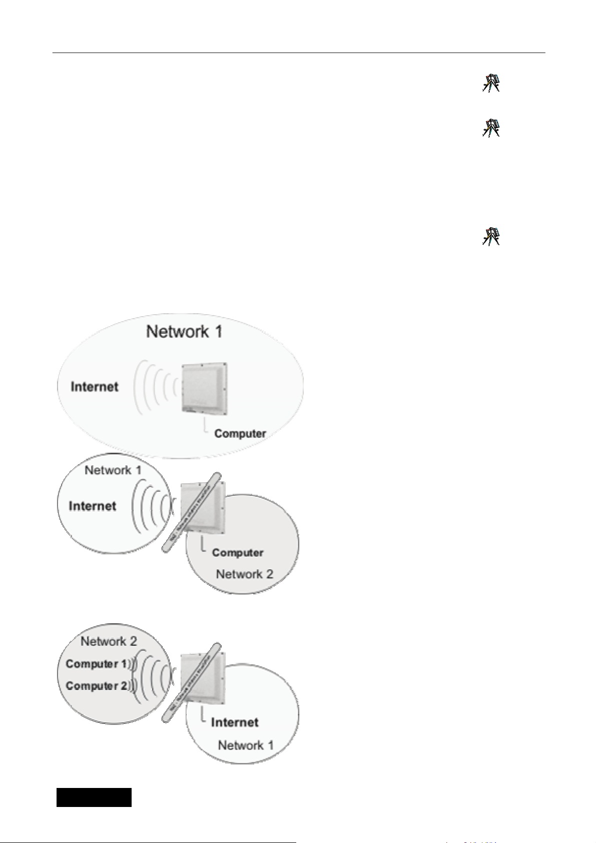
Konfiguration des drahtlosen Zugriffspunkts LAN
10.2.7 Richtungstabelle 7
Auf der Seite „Richtungstabelle“ finden Sie aktuelle Regeln der Ausrichtung (Routing) der Einheit. Diese
Regeln kann man im Menü statische Wege richten.
10.2.8 ARP-Tabelle 8
Die Seite ARP-Tabelle informiert über die MAC-Adressen der angeschlossenen Einrichtungen sowohl auf der
drahtlosen als auch auf der metallischen Seite der Einheit.
10.3 Betriebsmoduseinstellung 9
Der erste Schritt bei der Einstellung der Einheit beruht auf der Wahl der Betriebsart aus der Sicht
der Routierung von Netzen. Dieses Konfigurationsangebot erreichen Sie mittels des Menüs
Netz&Firewall Lesezeichen Netzbetriebsart. Die Einheit bietet 3 Operationsbetriebsarten.
In der Default-Einstellung ist die Einheit in der
Betriebsart 1 - BRIDGE, wo beide Schnittstellen
auf derselben Ebene sind. Von den beiden ist die
Einheit an derselben IP-Adresse erreichbar. .
Diese Einstellung ist bei der Anwendung der
Einrichtung als Zugriffspunkt und in einigen Fällen
auch in der Betriebsart der Klienteneinrichtung
üblich. Sämtliche Einstellungen, die den Betrieb
der Übersetzung der NAT-Adressen betreffen, sind
nicht erreichbar.
Die Betriebsart 2 wird für den Betrieb der
Klienteneinheit typisch angewandt. Die Einheit ist
dann mittels der drahtlosen Schnittstelle an das
Internet angeschlossen. Für den Anschluss der
Klientencomputer können die Porte auf PSW-105
verwendet werden. Für die Computer der Klienten
wird dann diese Einheit als Ausgangstor verwendet.
Für die Konfiguration ist die Einheit an den
entsprechenden IP-Adressen der LAN- und WANSeite. Diese Einstellung ist in der Regel mit der
Funktion des DHCP-Servers kombiniert, der die
Adressen den einzelnen Computern automatisch
zuordnet.
Durch die typische Anwendung der Betriebsart 3
wird die Einheit als üblicher drahtloser Router, zum
Beispiel für den ADSL- oder Ethernetanschluss. In
diesem Fall ist das Internet per Kabel in den Switch
PSW-105 des als Ethernet bezeichneten Ports
zugeleitet. Die Klientencomputer sind dann drahtlos
angeschlossen. In diesem Fall ist das Radio in die
Betriebsart Zugriffspunkt zu stellen.
Deutsche Version
10
Page 48

Konfiguration des drahtlosen Zugriffspunkts LAN
10.4 Einstellung des drahtlosen Teils
Diese Multifunktionseinheit arbeitet in mehreren Operationsbetriebsarten: Zugriffspunkt, Station,
WDS-System, WDS-Zugriffspunkt und Wiederholer. Am häufigsten wird die Einheit im Operationsmodus
Station angewandt, für das sie bestimmt ist.
Der Betriebsmodus “Zugriffspunkt“ wird dann angewandt, wenn diese Einheit als Zentralpunkt Ihres
drahtlosen Netzes dient, an den anschließend weitere drahtlose Adapter im Modus Station – Infrastruktur
angeschlossen werden.
Das Operationsmodus “Station” wird weiter in zwei Typen geteilt. Die “Station“ wird im Falle der
Netze angewandt, wo der zentrale Zugriffspunkt besteht, wie oben beschrieben ist. Bei der Anwendung des
Operationssystems “Ad Hoc“ kann man das Netz direkt unter den einzelnen Adaptern ohne Teilnahme des
zentralen Zugriffspunkts bilden. (Kommunikation vom Typ Peer-to-Peer)
Die Operationsbetriebsart vom Typ “WDS-System” (sonst auch BRIDGE genannt) ist vor allem für
die Durchschaltung von zwei (“Bridge Point-to-Point”) oder mehreren (“ Bridge Point-to-Multipoint”) LANNetzen zusammen bestimmt.
Bei der Einstellung der Operationsart Wiederholer verhält sich dann die Einheit zugleich als
Zugriffspunkt und zugleich als Klientenadapter der übergeordneten Einheit in der Betriebsart Access Point.
Warum ist die Betriebsart WDS-System/Bridge zur Durchschaltung der LAN-Netze mehr geeignet?
Bei der Anwendung der Operationsbetriebsarten Station (beide Typen) kommt es bei den Einheiten im
Einklang mit den WiFi-Standards zur Änderung des Paketkopfs in der zweiten Ebene – also zum Umtausch
der MAC-Adresse der Endeinrichtung gegen die MAC-Adresse der Einheit. In manchen Applikationen, wo
sich hinter der Einheit mehr als eine Endeinrichtung befinden, kann dieser Umtausch der Netzadresse
Probleme bewirken. In den Betriebsarten Bridge verhält sich die Einheit dagegen auch auf der zweiten
Ebene ganz transparent und die MAC-Adressen im Paketkopf lässt sie ohne Änderung.
Ein spezielles Beispiel der Betriebsarten – das WDS-System - ist dann der Typ “WDS-Zugriffspunkt“.
In dieser Operationsbetriebsart kann die Einheit zugleich als Zugriffspunkt sowie als Bridge ausgenutzt
werden, die die LAN-Netze verbindet.
10.4.1 Einstellung der Grundparameter
der drahtlosen Übertragung:
10
Auf er Seite Grundeinstellung im Menü Drahtloser Teil definieren Sie die wichtigsten Parameter für
die Radiodatenübertragung. Ihre Beschreibung finden Sie in folgender Tabelle:
Parameter Beschreibung
Netzname – SSID
(grundlegende Einstellung des
Radiomoduls)
Betriebstyp:
(grundlegende Einstellung des
Radiomoduls)
Der SSID-Parameter (bis 31 ASCII-Zeichen) stellt einen Schlüssel dar,
aufgrund dessen es zur Verbindung der einzelnen Adapter im Rahmen
des drahtlosen Netzes kommt. Durch die Einstellung der verschiedenen
Netzschlüssel können Sie das Funktionieren von einigen drahtlosen
Netzen in demselben Bereich und im Rahmen desselben
Frequenzbereichs sicherstellen. Der SSID ist auf dem Zugriffspunkt und
allen Klientenadaptern, die daran angeschlossen werden,
übereinstimmend einzustellen. Standardmäßig ist dieser Schlüssel auf
“GWP-207Vet“ eingestellt, wir empfehlen jedoch diese Einstellung bei der
Installation zu ändern. Der SSID wird in den Betriebsarten
“Zugriffspunkt“, “AD HOC-Station“, “Station - Infrastruktur“, “WDSSYSTEM“ und “WDS-Zugriffspunkt“ eingestellt.
Diese Position gibt dem Anwender die Möglichkeit, die Betriebsart der
Einheit nur für den Standard 802.11b, nur für den Standard 802.11g oder
Deutsche Version
für beide Standards gleichzeitig zu definieren.
11
Page 49

Konfiguration des drahtlosen Zugriffspunkts LAN
A
Operationskanal:
(grundlegende Einstellung des
Radiomoduls)
Norm für WiFi
(grundlegende Einstellung des
Radiomoduls)
MAC-Adresse:
(Einstellung WDS/Bridge)
Absicherung einstellen:
(Einstellung WDS/Bridge)
Statistiken abbilden:
(Einstellung WDS/Bridge)
Angeschlossene Stationen:
(grundlegende Einstellung des
Radiomoduls)
Verfügbare Netze:
(grundlegende Einstellung des
Radiomoduls)
Durch diese Einstellung definiert der Anwender den Operationskanal der
Einheit. Für die Anwendung im Rahmen der Staaten der Europäischen
Union (abgesehen von Spanien) stehen insgesamt 13 Kanäle zur
Verfügung. Die Auswahl des Operationskanals wird in der Betriebsart
“Station – Infrastruktur“ nicht durchgeführt, in der der Kanal gemäß dem
Zugriffspunkt mit der identischen ESSID-Einstellung automatisch
eingestellt ist.
Bezug auf die Breite des ausgenutzten Frequenzbands kommt es zur
Überdeckung bzw. Überlappung der einzelnen Kanäle. Deshalb
erreichen Sie, wenn diese Möglichkeit vorhanden ist, die besten
Ergebnisse bei der Anwendung der WiFi-Zugriffspunkte so, dass sich die
Einheiten im gegebenen Bereich zumindest 3 bis 5 Kanäle voneinander
befinden. Zum Beispiel die Kanäle 1, 7, 13 benutzen, wo es zu keiner
gegenseitigen Störung mehr kommt.
In diesem Fenster wählen Sie die Norm für den Betrieb des Radioteils.
Für die Anwendung in der Tschechischen Republik wählen Sie ETSI.
In den Betriebsarten vom Typ Bridge und WDS-System sind MAC-
das System zur gegenseitigen Identifikation der Mitglieder der jeweiligen
Bridge- oder WDS-Struktur ausnutzt.
In den Operationsbetriebsarten vom Typ WDS können Sie aus
Sicherheitsgründen diese Taste für die Einstellung der
Übertragungschiffrierung nutzen.
In der Betriebsart WDS können Sie mittels dieser Taste die Tabelle mit
statistischen Informationen über Übertragungen der einzelnen WDSKlienten erscheinen lassen.
Durch die Betätigung der Taste “Aktive Stationen abbilden“ kommt es
zum Öffnen des Fensters mit der Übersicht der aktuell angeschlossenen
Klienten und der Übertragungsparameter dieser Stationen.
Durch die Betätigung der Taste für die Durchsuchung der verfügbaren
Netze im Operationsmodus Station wird von Ihnen die Tabelle der
verfügbaren drahtlosen Netze abgerufen. Durch die Auswahl des
drahtlosen Netzes und die Betätigung der Taste Anschließen wird Ihre
Einheit für den Anschluss zum jeweiligen Netz automatisch konfiguriert.
Wenn das Netz eines der Absicherungsprotokolle verwendet, ist die
eigentliche Absicherung manuell einzustellen.
Überdeckung der Operationskanäle
Hinsichtlich der Teilung des Frequenzbands in 13 Kanäle und im
dressen aller angeschlossenen drahtlosen Einheiten zu definieren, die
Betätigen Sie für die Abspeicherung der Änderungen die Taste “Anwenden“ in der linken Seitenecke. Jetzt
können Sie zur Einstellung weiterer Parameter übergehen oder anfangen Ihre Einheit zu benutzen.
10.4.2 Fortgeschrittene Einstellungen der Funkübertragung 11
Auf dieser Seite kann man die den drahtlosen Betrieb beeinflussenden Parameter detaillierter
eingeben. Die Parameter sind defaultmäßig so eingestellt, dass es nicht nötig ist, sie beim üblichen Betrieb
zu ändern, dennoch kann deren Optimierung die Erhöhung der Übertragungsgeschwindigkeit oder eine
niedrigere Fehlerrate der Übertragung bringen.
Parameter Beschreibung
Typ der Authentifikation
Deutsche Version
Dieses Fenster bietet drei Möglichkeiten. Bei der Wahl der Möglichkeit
„Offenes System“ kann ans Netz jegliche Station angeschlossen werden,
12
Page 50

Fragmentierungsebene
Konfiguration des drahtlosen Zugriffspunkts LAN
abgesehen von der Chiffrierung. Wenn Sie den „Gemeinsam genutzten
Schlüssel“ wählen, dann kann man sich an das Netz nur durch die
Einheit anschließen, die über denselben eingestellten gemeinsam
genutzten Schlüssel in der Einstellung der Absicherung verfügt. Der Wert
„Automatisch“ kombiniert dann die beiden Betriebsarten.
Die Fragmentierungsebene bestimmt die maximale Paketgröße bei der
Fragmentierung der Daten zur Absendung. Falls Sie einen zu niedrigen
Wert einstellen, kommt es zur Senkung der Leistung.
RTS-Ebene
Beacon-Intervall des Pakets
Liniengeschwindigkeit
DTIM-Periode
Typ der Präambel
SSID verstecken
Funktion IAPP
Schutz 802.11g
Isolation der drahtlosen
Klienten
Wenn die Paketgröße im Vergleich zu dem RTS-Grenzwert kleiner ist,
verwendet der Zugriffspunkt zur Absendung dieses Pakets den
Mechanismus RTS/CTS nicht.
Das Zeitintervall, innerhalb dessen der Zugriffspunkt das Signal (Beacon)
sendet. Das Signal dient zur Synchronisierung des drahtlosen Netzes.
Die Überstragungsgeschwindigkeit bestimmt die Geschwindigkeit der
Datenübertragung, die von diesem Zugriffspunkt angewandt wird. Der
Zugriffspunkt verwendet zur Übertragung von Paketen die
höchstmögliche ausgesuchte Übertragungsgeschwindigkeit.
DTIM ist der Bestandteil des Beacon-Pakets, der die Einheiten in der
Betriebsart Energieeinsparung darüber informiert, dass die
Datenübertragung folgen wird. Bei der Erhöhung dieses Werts verlängert
sich die Verzögerung zwischen dem Zustand der Energieeinsparung und
dem Übergang in den Betriebsmodus.
Der Typ der Präambel bestimmt die Länge des CRC-Blocks im Rahmen
während der drahtlosen Kommunikation. Die Möglichkeit „Kurzeinleitung“
ist in drahtlosen Netzen mit dem Hochbetrieb geeignet. Die Möglichkeit
„Langeinleitung“ kann eine zuverlässigere Kommunikation bieten.
Wenn Sie die Funktion „SSID verstecken“ verbieten, kann jede drahtlose
Station, die im Bedeckungsbereich dieses Zugriffspunkts platziert ist,
seine Anwesenheit leicht feststellen. Wenn Sie ein öffentliches drahtloses
Netz gestalten, wird es empfohlen, diese Funktion zu bewilligen. Die
Bewilligung der Funktion „SSID verstecken“ kann eine bessere
Absicherung bieten.
Wenn Sie die IAPP-Funktion bewilligen, wird der Zugriffspunkt
Informationen über zugeordnete drahtlose Stationen an seine Nachbarn
automatisch senden. Dies erleichtert einen kontinuierlichen Übergang der
drahtlosen Station unter den Zugriffspunkten. Wenn Ihr drahtloses LANNetz mehr als einen Zugriffspunkt enthält und es erforderlich ist, dass
sich die drahtlosen Stationen bewegen, wird es empfohlen, diese
Funktion zu bewilligen. Das Verbot der „IAPP-Funktion“ kann eine
bessere Absicherung gewähren.
Diese Funktion wird auch CTS-Schutz genannt. Es wird empfohlen, den
Schutzmechanismus zu bewilligen. Es ermöglicht, die Kollisionsrate
zwischen den Stationen 802.11b und 802.11g zu reduzieren. Wenn die
Schutzbetriebsart bewilligt ist, ist die Durchlässigkeit des Zugriffspunkts
aufgrund des Übertragungsbedarfs einer hohen Rahmenanteils
unerheblich niedriger.
Diese Funktion wird lediglich in der Operationsbetriebsart Zugriffspunkt
angewandt. Nach der Aktivierung dieser Funktion kommt es zur
Verriegelung der Kommunikation unter den einzelnen Klienten im
Rahmen des Zugriffspunkts.
Deutsche Version
13
Page 51

Konfiguration des drahtlosen Zugriffspunkts LAN
Sendeleistung 802.11b
Sendeleistung 802.11g
Eingangsverstärkung
Speichern Sie durch das Anklicken der Taste Anwenden im Unterteil des Bildschirms die oben
angeführte Konfiguration ab. Jetzt können Sie weitere Teile konfigurieren oder anfangen, den Zugriffspunkt
anzuwenden.
Es ist hier möglich, die Sendeleistung für den Betrieb gemäß dem
Standard 802.11b zu definieren, also mit der CCK-Modulation. Machen
Sie sich bei der Leistungseinstellung jeweils mit Einschränkungen
bekannt, die auf dem Gebiet gültig sind, wo die Einheit angewandt
wird. Befolgen Sie für die Anwendung in der Tschechischen
Republik die Weisungen im Kapitel „Anwendung der Einrichtung“.
Es ist hier möglich, die Sendeleistung für den Betrieb gemäß dem
Standard 802.11g zu definieren, also mit der OFDM-Modulation. Machen
Sie sich bei der Leistungseinstellung jeweils mit Einschränkungen
bekannt, die auf dem Gebiet gültig sind, wo die Einheit angewandt
wird. Befolgen Sie für die Anwendung in der Tschechischen
Republik die Weisungen im Kapitel „Anwendung der Einrichtung“.
Es wird dadurch die Verstärkungsebene des Eingangsvorverstärkers
beim Signalempfang eingestellt. Durch die Einstellung von höheren
Werten kann man auch früher unverfügbare drahtlose Netze fangen,
dennoch kommt es zugleich zum Geräuschanstieg im empfangenen
Signal und damit auch zur höheren Fehlerrate der Übertragung.
10.4.3 Absicherung 12
Der Zugriffspunkt bietet alle Absicherungsfunktionen des drahtlosen LAN-Netzes, einschließlich
WEP, IEEE 802.11x, IEEE 802.11x mit WEP, WPA mit dem im Voraus gemeinsam genutzten Schlüssel und
WPA mit Servern RADIUS. Diese Absicherungsfunktionen ermöglichen, den unbefugten Zugriff in Ihr
drahtloses LAN-Netz zu vermeiden. Überprüfen Sie, ob alle drahtlosen Stationen dieselbe
Absicherungsfunktion anwenden.
Außer den übliche Chiffrierungstypen ist es auch möglich, immer zusätzlich die Vorüberprüfung mittels des
Servers RADIUS und des Standards 802.1x einzuschalten. Das Protokoll IEEE 802.1x ist ein
Überprüfungsprotokoll. Jeder Anwender muss sich vor dem Zugriff auf das drahtlose LAN-Netz mittels einer
gültigen Rechnung zum Zugriffspunkt anmelden. Die Überprüfung wird vom Server RADIUS durchgeführt. In
dieser Betriebsart wird der Anwender lediglich mittels des Protokolls IEEE802.1x überprüft, während der
Kommunikation wird keine Chiffrierung von Daten vorgenommen. Das Protokoll 802.1x ohne Chiffrierung
kann man in der Betriebsart „Zugriffspunkt“ und in der Betriebsart „WDS-Zugriffspunkt“ verwenden.
Anmerkung: In der Betriebsart „WDS-Zugriffspunkt“ kann der Zugriffspunkt als Station und
Zugriffspunkt zugleich arbeiten. Die Einstellung der Absicherung in der Betriebsart „WDS-Zugriffspunkt“
bezieht sich lediglich auf die Funktionen des Zugriffspunkts.
Parameter Beschreibung
Absicherungstyp:
WEP-Format des Schlüssels:
WEP-Schlüssel:
Format des gemeinsam
genutzten Schlüssels:
Gemeinsam genutzter
Schlüssel:
In dieser Position können Sie den Typ der Absicherung wählen, die
angewandt wird. Es stehen die Typen WEP, WPA und WPA mit der
Förderung des RADIUS-Servers zur Verfügung.
Diese Position wird bei der WEP-Chiffrierung angewandt. Sie bezeichnet
das Format, in dem die Schlüssel eingegeben werden. Zur Wahl sind die
Typen ASCII und die Hexadezimale Form.
Der Wert des Ausgangsschlüssels für die WEP-Chiffrierung.
In dieser Position wählen Sie das Schlüsselformat des WPA-Systems. Es
ist erneut von den Typen ASCII oder Hexadezimal zu wählen.
Schlüssel für die Chiffrierung von Daten im WPA-System.
10.4.3.1 WEP-Chiffrierung 13
Für die Einstellung der Chiffrierungsschlüsse der WEP-Absicherung dient die Seite „WEPChiffrierung“. Die Beschreibung der einzelnen Parameter finden Sie in folgender Tabelle:
Deutsche Version
14
Page 52

Konfiguration des drahtlosen Zugriffspunkts LAN
Parameter Beschreibung
Schlüssellänge Es ist möglich, den 64-Bit- oder den 128-Bit-Schlüssel zur Chiffrierung
der übertragenen Daten zu wählen. Der längere WEP-Schlüssel gewährt
eine höhere Absicherungsebene, aber eine niedrigere Durchlässigkeit.
Schlüsselformat Für den WEP-Schlüssel ist es möglich, die ASCII-Zeichen
(alphanumerisches Format) oder hexadezimale Ziffern (im Bereich „A-F“,
„a-f“ und „0-9“) zu wählen. Zum Beispiel:
ASCII-Zeichen: guest
Hexadezimale Ziffer: 12345abcde
Ausgangsschlüssel Wählen Sie einen von den vier Schlüsseln für die Chiffrierung von Daten.
Chiffrierungsschlüssel 1 – 4 Die WEP-Schlüssel dienen zur Chiffrierung der übertragenen Daten im
Speichern Sie durch das Anklicken der Taste Anwenden im Unterteil des Bildschirms die oben
angeführte Konfiguration ab. Jetzt können Sie weitere Teile konfigurieren oder anfangen, den Zugriffspunkt
anzuwenden.
Verwenden Sie nur den im Fenster „Ausgangsschlüssel“ ausgewählten
Schlüssel.
drahtlosen Netz. Füllen Sie das Textfeld anhand der unten angeführten
Regeln aus.
64-Bit-WEP: Geben Sie als Chiffrierungsschlüssel 10 hexadezimale
Ziffern (in Bereich „A-F“, „a-f“ und „0-9“) oder 5 ASCII-Zeichen ein.
128-Bit-WEP: Geben Sie als Chiffrierungsschlüssel 26 hexadezimale
Ziffern (in Bereich „A-F“, „a-f“ und „0-9“) oder 5 ASCII-Zeichen ein.
10.4.3.2 WPA/WPA2 14
Die Methode WPA (Wi-Fi Protected Access ) ist ein fortgeschrittener Absicherungsstandard. Für die
Überprüfung der drahtlosen Stationen und die Chiffrierung von Daten ist es möglich, den im Voraus
gemeinsam genutzten Schlüssel zu verwenden. Es werden häufige Änderungen des Chiffrierungsschlüssels
mittels der Methoden TKIP oder CCMP(AES) vorgenommen. Es ist deshalb beim Angriff nicht einfach, den
Chiffrierungsschlüssel durchzubrechen. Dadurch wird die Absicherung des drahtlosen Netzes bedeutend
verbessert. Das Chiffrieren mit dem im Voraus gemeinsam genutzten WPA-Schlüssel kann man in den
Betriebsarten “Zugriffspunkt“, “AD HOC-Station“, “Station - Infrastruktur“, und “WDS-Zugriffspunkt“
anwenden.
Parameter
Überprüfungsmodus Sie können die Überprüfung mittels des im Voraus gemeinsam genutzten
Schlüsselformat Es ist möglich, für den im Voraus gemeinsam genutzten WEP-Schlüssel
Gemeinsam genutzter Schlüssel Der im Voraus gemeinsam genutzte Schlüssel zur Überprüfung und
Beschreibung
Schlüssels oder des Radius-Servers wählen. In diesem Fall wird für die
Überprüfung der Radius-Server benutzt, der im Oberteil des Bildschirms
eingegeben ist.
die Eingangsphrase (alphanumerisches Format) oder hexadezimale
Ziffer zu wählen (im Bereich „A-F“, „a-f“ und „0-9“). Zum Beispiel:
Eingangsphrase: iamguest
Hexadezimale Ziffern: 12345abcde
Chiffrierung der im drahtlosen Netz übertragenen Daten. Füllen Sie das
Textfeld anhand der unten angeführten Regeln aus. Hex: als im Voraus
gemeinsam genutzte Chiffrierungsschlüssel geben Sie 64 hexadezimale
Werte (im Bereich „A-F“, „a-f“ und „0-9“) oder eine Eingangsphrase in der
Länge von mindestens 8 Zeichen ein.
Deutsche Version
15
Page 53

Konfiguration des drahtlosen Zugriffspunkts LAN
A
A
A
A
A
A
Durch die Betätigung der Taste Anwenden im Unterteil des Bildschirms speichern Sie die oben angeführte
Konfiguration ab. Jetzt können Sie weitere Teile konfigurieren oder anfangen, den Zugriffspunkt
anzuwenden.
10.4.4 Filtrierung der MAC-Adressen 15
Der Zugriffspunkt ermöglicht das Filtrieren der MAC-Adressen, das den Einheiten mit einer
unbekannten (unbewilligten) MAC-Adresse den Zugriff auf das drahtlose Netz vermeidet.
Parameter Beschreibung
Einstellung des Filters der MACAdressen
Tabelle der Filtrierung der MACAdressen
Hinzufügen einer MAC-Adresse
in die Tabelle
Löschung ausgewählter MACAdressen
Sie bewilligt oder verbietet die Funktion Filtrierung von MAC-Adressen.
Diese Tabelle enthält Aufzeichnungen der MACStationen, denen Sie den Zugriff auf das Netz ermöglichen wollen. Das
Fenster „Kommentar“ enthält die Beschreibung der drahtlosen Station mit
der jeweiligen MACUnterscheidung der drahtlosen Stationen.
Füllen Sie im angeführten bereich „Neu“ die Fenster „MAC„Anmerkung“ der drahtlosen Station aus, die Sie hinzufügen möchten,
und klicken Sie die Taste „Hinzufügen“ an. Die drahtlose Station wird
dann in die „Tabelle der Filtrierung der MAC-Adressen“ hinzugefügt.
Wenn Sie eine der MACMACaus, die Sie entfernen wollen und klicken Sie die Taste „Ausgewähltes
löschen“. Wenn Sie aus der Tabelle alle MACwollen, klicken Sie die Taste „Alles entfernen“ an.
dressen“ entfernen wollen, wählen Sie in der Tabelle Adressen
dresse. Dieses Fenster erleichtert die
dressen aus der „Tabelle der Filtrierung der
dressen der drahtlosen
dresse“ und
dressen entfernen
Alles löschen
Durch die Betätigung der Taste Anwenden im Unterteil des Bildschirms speichern Sie die oben angeführte
Konfiguration ab. Jetzt können Sie weitere Teile konfigurieren oder anfangen, den Zugriffspunkt
anzuwenden.
Durch das Anklicken der Taste „Alles löschen“ ist es möglich, die
gesamte Tabelle zu löschen.
10.5 IP-Einstellung
Im als Ethernetteil bezeichneten im Punkt des Hauptangebots kann man sämtliche mit der
Anwendung des TCP/IP-Protokolls verbundene Parameter definieren.
10.5.1 TCP/IP-Einstellung des LAN-Ports 16
Auf dieser Seite können Sie die LAN-Schnittstelle betreffende Parameter des TCP/IP-Protokolls
einstellen, also die Schnittstelle, die in der Operationsbetriebsart ROUTER ins Lokalnetz hinzielt. Diese
Einstellung wird auch in der Operationsbetriebsart BRIDGE angewandt. Außer den standardmäßigen
TCP/IP-Parametern wie IP-Adresse, Netzmaske und Ausgangstor werden auch Parameter definiert, die mit
der Ausnutzung der DHCP-Dienste verknüpft sind.
DHCP kann in mehreren Betriebsmodi angewandt werden:
DHCP-Klient: in dieser Betriebsart erwartet die Einrichtung die Zuteilung eigener TCP/IP-Parameter
durch den übergeordneten DHCP-Server.
DHCP-Server: bei der Ausnutzung dieser Operationsbetriebsart ist im Gegenteil die eigentliche
Einheit der Informationsgeber bezüglich der TCP/IP-Einstellung für weitere Klienten. Es werden Parameter
IP-Adresse, Maske und Tor übergeben. In der Position „Adressenbereich für DHCP“ kann definiert werden,
welche Adressen den Klienten zugeordnet werden. Nach der Betätigung der Taste „Klienten abbilden“ wird
das Verzeichnis der aktuell zugeordneten Adressen abgebildet.
Deutsche Version
16
Page 54

Konfiguration des drahtlosen Zugriffspunkts LAN
DHCP-Aus: in diesem Falle werden Dienste des DHCP-Protokolls nicht genutzt.
Eine weitere Einstellmöglichkeit ist dann die Einschaltung des Richtungsprotokolls Spanning Tree, das
durch den Standard 802.1d definiert ist. Das Klonen der MAC-Adresse ist eine für den Fall bestimmte
Funktion, wenn es erforderlich ist, die Konfiguration der HW-Adresse der LAN-Schnittstelle zu ändern.
10.5.2 TCP/IP-Einstellung des WAN-Ports
Auf dieser Seite definieren Sie die Einstellung der ins Internet orientierten drahtlosen Schnittstelle.
Wenn Sie die Einheit in der Betriebsart BRIDGE anwenden, werden diese Einstellungen nicht genutzt. Diese
Seite ist dynamisch, ihr Aussehen ändert sich je nach dem aktuell gewählten Anschlusstyp ans Internet.
Über die Wahl des geeigneten Anschlusstyps entscheidet die Anwendungsart der Einheit, gegebenenfalls
Ihr Konnektivitätsgeber. Diese Typen gibt es insgesamt 5:
10.5.2.1 Statische IP-Adresse
Eine Betriebsart, bei der die IP-Adresse in die Einrichtung manuell eingegeben wird. Außer der IPAdresse, dem Tor und der Maske werden noch drei DNS-Namenserver eingegeben, die sich beim Betrieb
gegenseitig sicherstellen. Die letzte eingegebene Position ist dann die mögliche Definition der MAC-Adresse
der WAN-Schnittstelle.
10.5.2.2 DHCP-Klient
Bei der Anwendung der Einstellung DHCP-Klient definieren Sie lediglich die Zuteilungsart der
Information über den DNS-Server, gegebenenfalls die MAC-Adresse des WAN-Ports. Sonstige TCP/IPParameter werden durch den übergeordneten DHCP-Server automatisch zugeteilt.
10.5.2.3 PPPOE
Die Einstellung für PPPOE (Point-To-Point Protocol Over Ethernet) wird durch die Geber des
Anschlusses ans Internet häufig genutzt. Es handelt sich um eine einfache Art einer überprüften Verbindung,
die durch den Namen und Passwort abgesichert sind, die bei der Konfiguration einzugeben sind. Weiter
werden der Verbindungstyp (Dauerverbindung, auf Abruf, manuell eingeleitet), die Frist, nach deren Ablauf
es zur automatischen Abschaltung kommt und die Maximalgröße des abgesandten Pakets definiert. Es
besteht hier wieder die Möglichkeit der manuellen Definition der MAC-Adresse der Schnittstelle.
10.5.2.4 PPTP
Die PPTP-Einstellung ist für den automatischen Anschluss an das virtuelle Privatnetz bestimmt. Die
Verbindung ist durch die IP-Adresse des Servers, den Anwendernamen und das Passwort definiert. Es
besteht wieder die Definierungsmöglichkeit der MTU-, DNS-Server und der MAC-Adresse der Schnittstelle,
weiter dann der Chiffrierungstyp MPPE oder MSCHAP. Setzen Sie sich zwecks der Erlangung der
Parameter für den Anschluss mit dem Verwalter des VPN-Netzes in Verbindung.
10.5.2.5 PPTP+DHCP
Genauso wie im vorangehenden Punkt ist diese Wahl für den Anschluss an das VPN-Netz bestimmt,
und zwar mit dem Unterschied, dass die lokale IP-Adresse vom im jeweiligen VPN situierten DHCP-Server
gewonnen wird.
Deutsche Version
17
Page 55

Konfiguration des drahtlosen Zugriffspunkts LAN
10.5.3 Tor und Ausrichtung 17
Auf der Seite Tor und Ausrichtung definieren Sie statische Positionen der Richtungstabelle für die
Sicherstellung der korrekten Funktion der Einheit in der Betriebsart Router. Für die Einstellung dieser
Parameter muss man die Struktur des Netzes kennen, in dem die Einheit installiert ist. Die Position
„Ausgangstor“ (Default gateway) bestimmt den Grenzrouter, an den sämtliche Pakets abgesandt werden,
deren Ausrichtung bzw. Hinzielung weder automatisch noch manuell durch die gestaltete Richtungsregel
(Routierungsregel) definiert ist.
10.6 Netz und Firewall
Außer der Grundeinstellung der im Kapitel 3.3 beschriebenen Betriebsart des Netzes finden Sie unter dem
Lesezeichen „Netz und Firewall“ folgende Möglichkeiten:
10.6.1 Blockierung der IP/MAC-Adressen, Blockierung der Porte18
Im Bezug auf die identische Ausrichtung der Konfigurationsmöglichkeiten der Lesezeichen
„Blockierung der IP-Adressen“ und „Blockierung der MAC-Adressen“ ist hier von uns die Abbildung nur der
einen von ihnen angeführt.
Die Positionen in der Tabelle Blockierung der IP-Adressen sind zur Einschränkung des Durchgangs
einiger Pakete angewandt, gerichtet aus dem Innennetz raus, was die Missbrauchmöglichkeit Ihres
Internetanschlusses genauso wie die ungewollte Entweichung der Informationen von einigen Stationen in
Ihrem Netz einschränkt.
Die Positionen in der Tabelle „Blockierung der MAC-Adressen“ ermöglichen, die Datenabsendung
von Ihrem Netz durch die Definition der auf die HW-Adressen der einzelnen Einrichtungen gebundenen
Rechte zu verhindern.
Die Positionen in der Tabelle „Blockierung der Porte“ ermöglichen die Einschränkung des Umfangs
der durchgehenden TCP/IP- oder UDP-Porte durch die Einheit. Durch diese Einstellung kann man zum
Beispiel die Verfügbarkeit einiger vom Außennetz gebotenen Dienste einschränken.
Für die einfachere Orientierung in den erstellten Tabellen ist es möglich, zu jeder eingegebenen Position
eine Anmerkung mit der Beschreibung der jeweiligen Regel zu gestalten.
10.6.2 Ausrichtung der Porte 19
Die Positionen in dieser Tabelle steuern die Umlenkung der kommenden Porte auf der
Außenschnittstelle des Tores an die beliebige IP-Adresse des Innennetzes. Dadurch können Sie gewählte
Computer im Innennetz als Server anwenden oder den Zugriff auf deren Fernverwaltung haben. Das Symbol
“S“ bedeutet die vorwärtsgerichtete Änderung der Quell- bzw. Ausgangsadresse, die für einige Programme
unerlässlich ist. Das Symbol “C“ bezeichnet die Änderung des Zielports (der zweite Wert wird zur Nummer
des Zielports).
10.6.3 DMZ-Einstellung (Entmilitarisierte Zone)
Durch die Anwendung der Funktion Entmilitarisierte Zone können Sie einen Computer von Ihrem
Netz direkt vom Internet zugänglich machen. Auf den Computer werden sämtliche Dienste gerichtet, außer
den Diensten, die durch den Router selbst gewährt werden.
10.7 Dienste
Im Lesezeichen des Hauptmenüs „Betätigung“ finden Sie Funktionen, die mit dem eigentlichen
Betrieb der Einheit verbunden sind, Funktionen für die Aktualisierung der Softwareausstattung,
Änderungen der Zugriffspasswörter usw.
10.7.1 Geschwindigkeitslimit 20
Auf dieser Seite kann die Geschwindigkeitseinschränkung definiert werden, die für die gesamte
Einheit gültig ist. Die Richtung für Upload und Download wird jeweils aus der Sicht des Klienten genommen.
Deutsche Version
18
Page 56

Konfiguration des drahtlosen Zugriffspunkts LAN
Für fortgeschrittene Anwender: Wenn die Einheit in der Operationsbetriebsart BRIDGE befindlich ist,
versteht sich unter dem Begriff Upload die Einschränkung der Sendung der Ethernetschnittstelle und unter
dem Begriff Download die Einschränkung der Sendung der drahtlosen Schnittstelle. In der
Operationsbetriebsart ROUTER kehren sich dann die Aufgaben der einzelnen Schnittstellen um.
10.7.2 DDNS-Einstellung
21
Die dynamische DNS ist ein Dienst, der es ermöglich, die gültige Domäne für die sich ändernde
(dynamische) IP-Adresse zu registrieren. Die Einheit fördert 2 Geber dieses Dienstes, die Gesellschaften
DynDNS und TZO. Bei der Gesellschaft TZO ist es möglich, die 30-tägige Probeversion dieses Dienstes
unentgeltlich zu erhalten. Mehr Infos finden Sie auf
www.tzo.com.
10.7.3 Zeitserver 22
Es ist möglich, auf dem Lesezeichen „Zeitserver“ die Konfiguration für die Synchronisierung mit dem NTPZeitserver zu definieren. Der Server ist entweder aus dem in Vorbereitung befindlichen Verzeichnis zu
wählen oder es ist ein eigener zu definieren.
10.7.4 Watchdog/Restart 23
Es kann aus Betriebsgründen manchmal geeignet sein, die Einheit in automatischen Intervallen neu
zu starten. Nutzen Sie in diesem Fall die Einstellung unter dem Lesezeichen „Watchdog/Restart“. Es ist
möglich, die Funktion einzuschalten aber auch die Zeit zu definieren, nach der der automatische Restart
erfolgen wird.
Die weitere Möglichkeit ist dann der Restart der Einheit beim Verlust der Verbindung mit der
jeweiligen IP-Adresse. Das Testintervall und weiter dann eine oder zwei IP-Adressen sind zu definieren.
Beim Test wird jeweils die IP-Adresse 1 geprüft. Wenn sie beim Test einen höheren Verlust als 20%
aufweist, wird es zum Testen der IP-Adresse 2 übergegangen. Wenn der Test der IP-Adresse gelingt,
erfolgt der Test der IP 2 nicht. Sollte nicht einmal die IP-Adresse 2 erreichbar sein, kommt es automatisch
zum Restart der Einheit.
10.7.5 Netztest 24
Das Lesezeichen „Netztest“ enthält übliche Instrumente für das Testen der Netze im TCP/IP-
Protokoll. Es sind Instrumente Ping, Arping und Traceroute verfügbar, einschließlich der entsprechenden
Parameter. Das Testergebnis wird im unteren Fenster angezeigt. Betätigen Sie nach der Eingabe der
Parameter die Taste ABSENDEN.
Deutsche Version
19
Page 57
Konfiguration des drahtlosen Zugriffspunkts LAN
Chapter 11 Verwaltung
11.1.1 Passwortänderung 25
Das Lesezeichen „Passwortänderung“ dient, wie schon der Name verrät, zur Änderung der
Zugriffspasswörter für die Betätigung der Einheit. Der Parameter „Superanwender ausschalten“ verriegelt
die Möglichkeit, sich mittels des durch den Hersteller eingegebenen nichtöffentlichen Passworts an die
Einheit anzuschließen.
11.1.2 Einspeicherung/Wiederherstellung der Konfiguration 26
Der Bildschirm Einspeicherung/Wiederherstellung der Konfiguration ermöglicht die Einspeicherung
der aktuellen Einstellung der Konfiguration des Zugriffspunkts. Die Einspeicherung der Konfiguration bietet
einen weiteren Schutz und eine geeignete Art, wenn es zu Problemen mit dem Zugriffspunkt kommt und es
nötig ist, die werkseitige Ausgangseinstellung erneut herzustellen. Wenn Sie die Einstellung der
Konfiguration einspeichern, können Sie die archivierte Konfiguration in den Zugriffspunkt mittels der Taste
„Wiederherstellen“ wieder einlesen. Bei ernsthaften Problemen können Sie die Möglichkeit
„Wiederherstellung der werkseitigen Ausgangseinstellung“ nutzen. Diese Möglichkeit stellt alle
Konfigurationswerte auf deren Ausgangswerte beim Einkauf des Zugriffspunkts.
11.1.3 Aktualisierung 27
Auf der Seite „Aktualisierung“ kann man die Aktualisierung der Software vornehmen, die von der
Einheit dann genutzt wird, wenn sich die Einheit nicht nach Voraussetzungen verhält, oder aufgrund der
Herausgabe einer neuen Version der steuernden Software. Betätigen Sie nach der Wahl der Datei mit der
Aktualisierung die Taste „Aufnehmen“. Die Aktualisierung selbst kann bis 180 Sekunden dauern –
unterbrechen Sie während dieser Laufzeit die Einspeisung der Einheit nicht. Wir empfehlen, diese
Aktualisierung ausschließlich mittels des Anschlusses durch das metallische Kabel durchzuführen.
Sollten Sie an die Einheit durch eine Linie über eine niedrigere Datendurchlässigkeit angeschlossen
werden, streichen Sie das Lesezeichen „langsames Upload“ an. Damit verlängert sich die Wartezeit auf
den Schluss der Übertragung.
11.1.4 www-Schnittstelle 28
Auf dieser Seite kann man Parameter der Schnittstelle für die Nachricht der Einheit und deren
Verfügbarkeit von den Einzelnen Porten konfigurieren. Weiter kann man den TCP/IP-Port für den Zugriff
definieren, was zum Beispiel dann geeignet ist, wenn der Port 80 aufgrund des Betriebs des www-Servers
in der DMZ freizugeben ist, oder mittels der Ausrichtung der Porte.
11.2 Restart
Wenn die Einheit aufhört, richtig zu reagieren, ist es möglich, den Fernrestart des
Operationssystems durchzuführen. Die Einstellung wird nicht geändert. Reset kann man durch die
Betätigung der Taste Restart unter dem Hauptangebot durchführen. Die Restart-Durchführung erfolgt sofort,
ohne Bestätigungsdialog.
Deutsche Version
20
Page 58

Chapter 12 Behebung von Störungen
Dieses Kapitel bietet die Lösung von Problemen, zu denen es bei der Installation und dem Betrieb des
Zugriffpunkts kommen kann.
21. Wie kann man die IP-Adresse und die MAC-Adresse des Computers manuell feststellen?
1) Lösen Sie im Windows-System das Programm „Auftragszeile“ aus.
2) Geben Sie den Auftrag Ipconfig /all ein und drücken Sie die Taste Enter
y Die IP-Adresse des Computers ist mit dem Namen IP-Adresse gekennzeichnet.
y Die MAC-Adresse ist mit dem Namen Physische Adresse gekennzeichnet.
22. Was ist AD-HOC?
Das drahtlose LAN-Netz vom Typ AD-HOC ist eine Computergruppe mit WLAN-Adaptern, die durch
das unabhängige drahtlose LAN-Netz durchgeschaltet sind.
23. Was ist Infrastruktur?
Die Konfiguration der Infrastruktur bezeichnet das gemeinsame drahtlose LAN-Netz und das feste
LAN-Netz (durchgeschaltet mittels eines Kabels).
24. Was ist BSS ID?
Die Gruppe der drahtlosen Stationen und der Zugriffspunkt gestalten die Gruppe BSS (Basic Service
Set). Die Computer in der BBS-Gruppe haben über denselben eingestellten BSS ID-Wert zu verfügen.
25. Was ist ESSID?
Die Konfiguration der Infrastruktur kann Roaming-Möglichkeiten für die Mobilarbeit fördern. Mehrere
BBS-Gruppen können als ESS (Extended Service Set) konfiguriert werden. Die Anwender im ESSRahmen können sich unter BSS frei bewegen, wobei der Daueranschluss an die Stationen des
drahtlosen Netzes und die Zugriffspunkte des drahtlosen LAN-Netzes bestehen bleibt.
26. Können die Daten bei der drahtlosen Übertragung abgehört werden?
Das WLAN-Netz bietet zwei Absicherungsarten. Auf der Hardwareseite mittels der DSSS-Technologie
(Direct Sequence Spread Spectrum), von der die übertragenen Daten durch Kodieren abgesichert
werden. Auf der Softwareseite bietet das WLAN-Netz die Chiffrierungsfunktion (WEP, WPA, WPA2),
die die Absicherung und die Zugriffskontrolle verbessert.
27. Was ist WEP?
WEP (Wired Equivalent Privacy) bezeichnet den Mechanismus der Datenabsicherung, der auf dem
Algorithmus des gemeinsam genutzten 64 (40)-Bit-Schlüssels basiert.
28. Was ist WPA?
WPA ist die Abkürzung für Wi-Fi Protected Access. Es handelt sich um ein Absicherungsprotokoll der
drahtlosen Netze 802.11. WPA bietet den Datenschutz mittels der Chiffrierung und verwendet die
Zugriffsteuerung und die Überprüfung der Anwender.
29. Was ist WPA2?
WPA2 bietet im Vergleich zu WPA einen stärkeren Mechanismus der Chiffrierung mittels des AESStandards (Advanced Encryption Standard).
30. Was ist MAC-Adresse?
Die MAC- (Media Access Control) Adresse ist eine einmalige durch den Hersteller jeder Einrichtung,
zum Beispiel dem Netzadapter, des Netzes Ethernet zugeordnete Nummer, und ermöglicht, die
Einrichtung auf der Hardware-Ebene zu identifizieren. Diese Nummer ist in allen üblichen Fällen eine
Dauernummer. Im Vergleich zu den IP-Adressen, die bei jeder Anmeldung des Computers ins Netz
geändert werden können, bleibt die MAC-Adresse der Einrichtung immer gleich und sie ist für die
Identifikation im Netz wichtig.
Page 59

Konfiguration des drahtlosen Zugriffspunkts LAN
Straight
Universal outdoor
Wireless CPE
GWP-106VE
C
o
r
e
Instrukcja obsługi
IEEE 802.11b/g
54Mb/s
Dla wersji firmware 1.5.6
Page 60

Konfiguration des drahtlosen Zugriffspunkts LAN
Spis treści
1 O produkcie.............................................................................1
1.1 Zawartość opakowania..................................................................... 1
1.2 Właściwości...................................................................................... 1
1.3 Specyfikacja..................................................................................... 1
1.4 Opis urządzenia ............................................................................... 2
1.4.1 Część zewnętrzna – ODU.......................................................................2
1.4.2 Część wewnętrzna – IDU........................................................................2
2 Konfiguracja............................................................................4
2.1 Wstęp............................................................................................... 4
2.1.1 Ustawienia PC.........................................................................................4
2.1.2 Konfiguracja przeglądarki Internetowej ...................................................7
2.1.3 Logowanie do urządzenia .......................................................................7
2.2 Statistics........................................................................................... 8
2.2.1 Unit Status...............................................................................................8
2.2.2 Reachable Networks .............................................................................13
2.2.3 Data.......................................................................................................13
2.2.4 Wireless Connection .............................................................................14
2.2.5 DHCP Clients ........................................................................................14
2.2.6 WDS Connection...................................................................................14
2.2.7 Routing Table........................................................................................14
2.2.8 ARP Table.............................................................................................14
2.3 Ustawianie trybu pracy................................................................... 15
2.4 Wireless ......................................................................................... 15
2.4.1 Basic Settings: ......................................................................................16
2.4.2 Advanced Settings ................................................................................17
2.4.3 Security .................................................................................................17
2.4.4 MAC address filtering ............................................................................19
2.4.5 WDS System.........................................................................................19
2.5 IP Settings...................................................................................... 20
2.5.1 IP Settings for LAN / IP Settings for management ................................20
2.5.2 IP Settings for WAN ..............................................................................20
2.5.3 Gateway and Routing............................................................................22
2.6 Nat&Firewall................................................................................... 22
2.6.1 IP Address filtering ................................................................................22
Page 61

Konfiguration des drahtlosen Zugriffspunkts LAN
2.6.2 MAC Address filtering............................................................................23
2.6.3 Port filtering ...........................................................................................23
2.6.4 Port Forwarding.....................................................................................23
2.6.5 IP/MAC Address/Port filtering, Port forwarding .....................................23
2.6.6 DMZ Settings ........................................................................................24
2.7 Services ......................................................................................... 24
2.7.1 Rate control...........................................................................................25
2.7.2 Dynamic DNS........................................................................................25
2.7.3 NTP Service ..........................................................................................25
2.7.4 Watchdog/Restart .................................................................................25
2.7.5 Network tests ........................................................................................26
2.8 Administration................................................................................. 26
2.8.1 Password ..............................................................................................26
2.8.2 Save/Restore settings ...........................................................................26
2.8.3 Upgrade ................................................................................................26
2.8.4 Web interface ........................................................................................27
2.9 Apply .............................................................................................. 27
2.10 Restart ........................................................................................ 27
3 Słowniczek ............................................................................28
4 Częste pytania.......................................................................29
Page 62

Chapter 13 O produkcie
Gratulujemy zakupu stacji bezprzewodowej GWP-106VE. Urządzenie przeznaczone jest do budowy
sieci bezprzewodowych w standardzie 802.11b i 802.11g. Urządzenie może pracować zarówno jako
bezprzewodowy punkt dostępowy – Access Point (tryb Access Point) jak i jako bezprzewodowa stacja
kliencka (tryb Client). Ponadto umożliwia połączenie wielu komputerów Ad Hoc bez użycia punktu
dostępowego AP oraz połączenia w trybie WDS.
Zastosowanie WEP, WPA, ESSID oraz filtrowania po MAC adresach zwiększa bezpieczeństwo
transmisji bezprzewodowej i zapobiega nieautoryzowanego dostępu do sieci bezprzewodowej.
Urządzenie posiada wbudowaną antenę panelową 12 dBi oraz umożliwia zarządzanie mocą z
poziomu strony www.
Urządzenie jest w prosty sposób zarządzane poprzez stronę www posiadającą kilka wersji
językowych. Oprogramowanie urządzenia (firmware) umożliwia również szerokopasmowy dostęp do sieci
Internet. Obudowa urządzenia umożliwia jego montaż na zewnątrz (część ODU) i stanowi ochronę przed
działaniem czynników atmosferycznych. Urządzenie jest zasilane poprzez zasilacz PoE przeznaczony do
pracy wewnątrz pomieszczeń osł
Instrukcja została opracowana dla wersji firmware 1.5.6. Kolejne wersje oprogramowania mogą
posiadać inne funkcje.
oniętych przed wpływem czynników atmosferycznych (część IDU).
13.1 Zawartość opakowania
Opakowanie powinno zawierać następujące elementy:
y Instrukcja Instalacji
y Stacja ODU GWP-106VE
y Zasilacz sieciowy 12V DC
y Jednoportowy zasilacz PoE
y Zasilacz PoE z wbudowanym switchem PSW-105 (opcja)
13.2 Właściwości
y Kompatybilność ze standardem IEEE 802.11b/g (DSSS) 2.4GHz
y Wodoszczelna wersja z wbudowaną antena panelową 12 dBi
y Zasilanie PoE (Power-over-Ethernet)
y Wysoka prędkość transmisji – do 54 Mb/s
y Prosta integracja z istniejącą siecią LAN
y Automatyczna redukcja prędkości transmisji w środowisku interferencyjnym
y Mechanizmy WEP 64/128 bit WEP oraz WPA zwiększające bezpieczeństwo transmisji
y Zarządzanie poprzez prosty interfejs wwwWbudowany serwer DHCP oraz mechanizm NAT
13.3 Specyfikacja
y Standardy: IEEE 802.11b/g (Wireless), IEEE 802.3 (LAN)
y Prędkość transmisji: 54/48/36/24/18/12/11/9/6/5,5/2/1Mb/s z automatyczną redukcją prędkości
transmisji w środowisku interferencyjnym
y Bezpieczeństwo: WEP 64/128 bit oraz WPA
y Zakres częstotliwości: 2.400~2.4835GHz (ISM)
y Modulacja:
802.11b – CCK dla 11/5,5 Mb/s, DQPSK dla 2 Mb/s, DBPSK dla 1 Mb/s
802.11g – BPSK, SPSK, 16QAM, 64QAM
– 1 –
Język Polski
Page 63

y Technologie Wireless: DSSS dla 802.11b, OFDM dla 802.11g
y Złącza LAN:
ODU-10/100 Mb/s RJ-45
IDU – 2 x RJ45 (Podstawowa wersja) lub 5 x RJ45 (PoE na porcie 1 lub 1 – 4) PSW-105 (opcja)
y Zasilacz: 12V DC
y Maksymalna moc 19,8 dBm
y Diody LED:
ODU – Power, Link, Transmisja
IDU – Power, 4x LAN Link/Transmisja/PoE, 1x LAN Link/Transmisji (opcja PSW-105)
y Zakres temperatury:
pracy: -35°C~65°C
składowania: -35°C~70°C
y Wilgotność: 10-90% (bez kondensacji)
y Certyfikaty: FCC, CE
13.4 Opis urządzenia
13.4.1 Część zewnętrzna – ODU
Urządzenie ODU przeznaczone jest do instalacji na maszcie. Posiada zintegrowaną na przednim
panelu antenę 12 dBi.
13.4.2 Instalacja
Od spodu urządzenie ODU posiada gniazdo ethernet wraz z osłoną wodoszczelną oraz przycisk
reset. Stacja ODU została tak zaprojektowana, aby mogła pracować zarówno z horyzontalną jak i
wertykalną polaryzacją zintegrowanej anteny. Instalacja urządzenia jest naprawdę bardzo prosta. Uważaj
przy instalacji, aby oba urządzenia: Access Point oraz Wireless Client były zamontowane z zachowaniem
tej samej polaryzacji. Do urządzenia dołączony jest kit montażowy zawierający zestaw śrub, ramię oraz
obejmę umożliwiającą przytwierdzenie ODU do masztu. Dodatkowo należy zabezpieczyć wszystkie złącza
osłonami wodoszczelnymi. Do urządzenia jest dołączona również wodoszczelna osłona na kabel ethernet.
Uszkodzenia powstałe wskutek nieodpowiedniego zabezpieczenia złącz nie podlegają gwarancji
.
13.4.3 Przycisk Reset
Urządzenie ODU wyposażone jest w przycisk umożliwiający restart urządzenia oraz przywrócenie
ustawień fabrycznych (reset). Przycisk jest zabezpieczony wodoszczelną osłoną i znajduje się obok
gniazda ethernet.
• Aby zrestartować urządzenie przytrzymaj przycisk Reset na włączonym ODU nie dłużej niż 4
sekundy. Ustawienia urządzenia zostaną zapamiętane.
• Aby przywrócić ustawienia fabryczne (Adres IP, Nazwa użytkownika i hasło) przytrzymaj
przycisk Reset na włączonym ODU dłużej niż 4 sekundy.
13.4.3.1.1. Część wewnętrzna – IDU
13.4.3.1.2. Podstawowa wersja
Do urządzenia mogą być dołączone dwie wersje zasilacza PoE. W standardowej wersji dołączany
jest tylko jednoportowy zasilacz PoE. Posiada on dwa gniazda RJ-45 na przednim panelu oznaczone jako
– 2 –
Język Polski
Page 64

LAN oraz PoE oraz jedno gniazdo zasilania na tylnym panelu. Gniazdo LAN służy do podłączenia sieci
ethernet (komputer PC, switch, hub) natomiast gniazdo PoE służy do podłączenia ODU. Po podłączeniu
zasilacza, ODU powinno zostać automatycznie uruchomione i połączone z siecią ethernet (podłączoną do
gniazda LAN). W tym momencie instalacją sprzętu została zakończona.
13.4.3.2 PSW-105
Do urządzenia może być również dołączony zasilacz PSW-105 jako dodatkowe akcesoria. Posiada
wbudowany switch 5 portowy. Urządzenie posiada zestaw diod LED sygnalizujących jego status.
LED Kolor Status Opis
świeci Urządzenie włączone.
nie świeci Brak zasilania, urządzenie wyłączone.
nie świeci Brak linku, nieaktywne PoE.
świeci czerwony Brak linku, aktywne PoE.
świeci pomarańcz. Brak linku, zasilanie z PoE.
miga pomarańcz. Link, transmisja danych, zasilanie z PoE.
świeci zielony Link, nieaktywne PoE.
miga zielony Link, transmisja danych, nieaktywne PoE.
świeci
miga Link, transmisja danych.
nie świeci Brak linku.
Link.
Power
1-4/POE
5
pomarańcz.
zielony
pomarańcz.
czerwony
zielony
13.4.3.2.1. Zasilanie PoE
IDU PSW-105 jest zasilaczem PoE (Power over Ethernet). W podstawowej konfiguracji tylko port 1
umożliwia zasilanie urządzenia ODU poprzez PoE. Zakładając zworkę J1 na płycie głównej PSW-105
następuje aktywacja modułu PoE dodatkowo dla portów 2 – 4, co umożliwia podłączenie do 4
zewnętrznych urządzeń ODU do jednego IDU (należy wtedy zastosować zasilacz 12 V DC 2 A).
13.4.3.2.2. IDU Power/Multiple Unit Connection
Gniazdo DC 12V umożliwia podłączenie zasilacza sieciowego. Wraz z IDU PSW-105 dostarczany
jest zasilacz sieciowy 12 V DC 500 mA. Umożliwia to poprawne działanie switcha i zasilanie jednego
urządzenia ODU skrętką o maksymalnej długości 15 m. W celu zwiększenia odległości ODU od IDU
można zastosować stabilizowany zasilacz o większym napięciu – maksymalnie do 18 V DC, co umożliwia
zwiększenie maksymalnej długości skrętki do 70 m. Aby podłączyć więcej niż jedno urządzenie ODU do
jednego PSW-105 należy założyć zworkę J1 oraz zastosować zasilacz o większej wydajności prądowej
(na każdy podłączony ODU 400 mA oraz 100 mA na każdy zdalnie zasilany switch).
13.4.3.2.3. Porty Ethernet 1 – 5
Urządzenie IDU należy podłączać do sieci LAN za pomocą skrętki ethernet kategorii 5e lub 6.
Ostrożnie podłączaj zewnętrze urządzenia StraightCore do portów z aktywnym zasilaniem PoE.
Podłączając inne urządzenia możesz zarówno zniszczyć zasilacz PoE jak i podłączane urządzenia.
– 3 –
Język Polski
Page 65
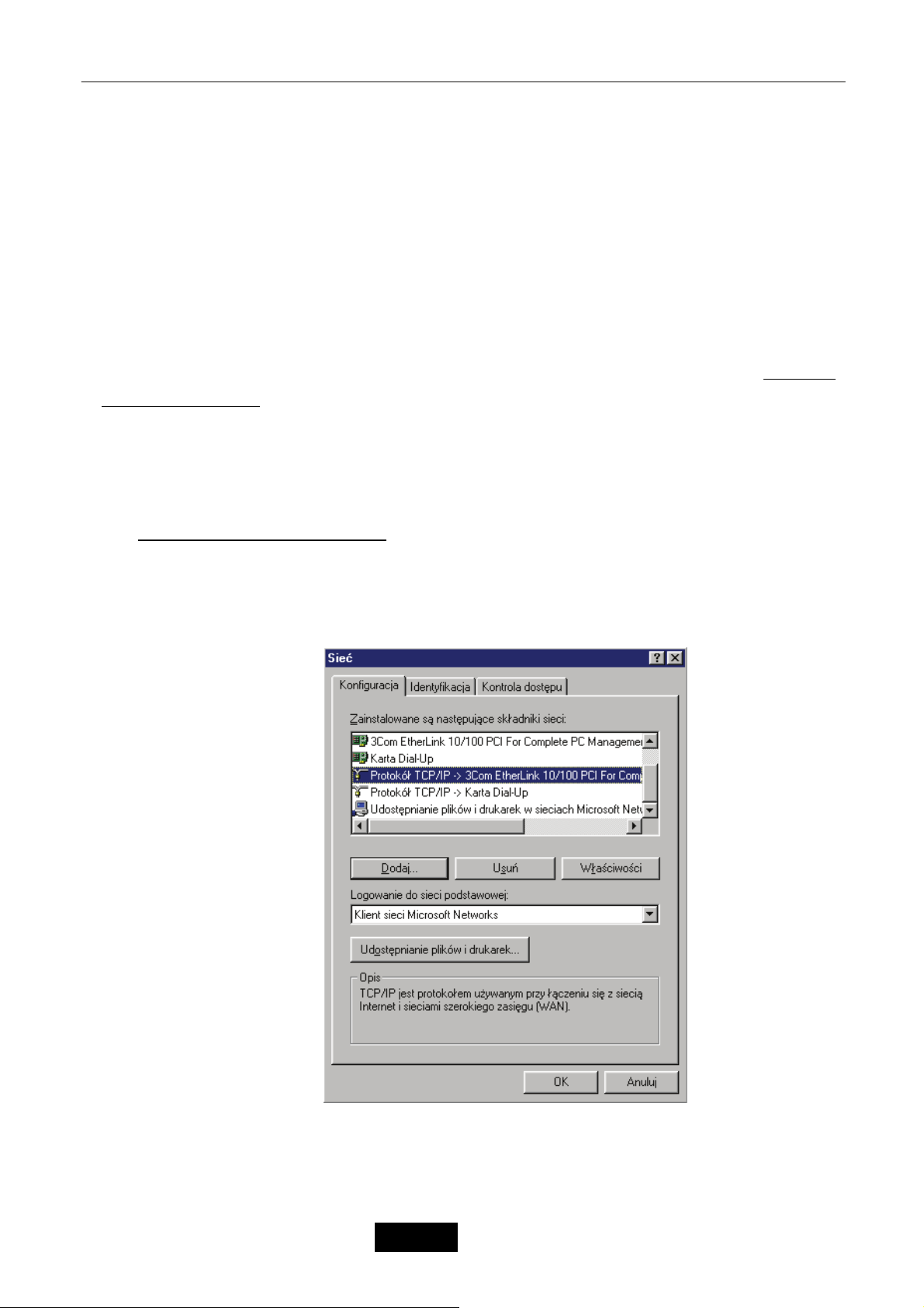
Chapter 14 Konfiguracja
14.1 Wstęp
Urządzenie może być konfigurowane i zarządzane poprzez dowolną przeglądarkę www.
14.2 Ustawienia PC
Sprawdź czy adres IP Twojego PC jest z tej samej podsieci, co adres urządzenia. Domyślnie
ustawienia urządzenia:
Domyślny adres IP: 192.168.1.1
Maska podsieci: 255.255.255.0
Konfiguracja parametrów TCP/IP Twojego PC:
dla systemów Windows 95/98/Me:
Odstraňování potíží
25. Wybierz z Menu Start – Ustawienia – Panel sterowania.
26. Zaznacz ikonę Sieć i podwójnie ją kliknij lub naciśnij prawym klawiszem myszy i wybierz
opcję „Otwórz”.
27. W zakładce Konfiguracja wybierz Protokół TCP/IP dla danej karty sieciowej i kliknij
przycisk „Właściwości”.
Sprawdź w zakładkach następujące parametry:
28.
• Zakładka Konfiguracja DNS: wybierz Wyłącz DNS.
• Zakładka Brama: pozostaw wszystkie pola puste.
• Zakładka WINS: wybierz Wyłącz WINS.
– 4 –
Język Polski
Page 66
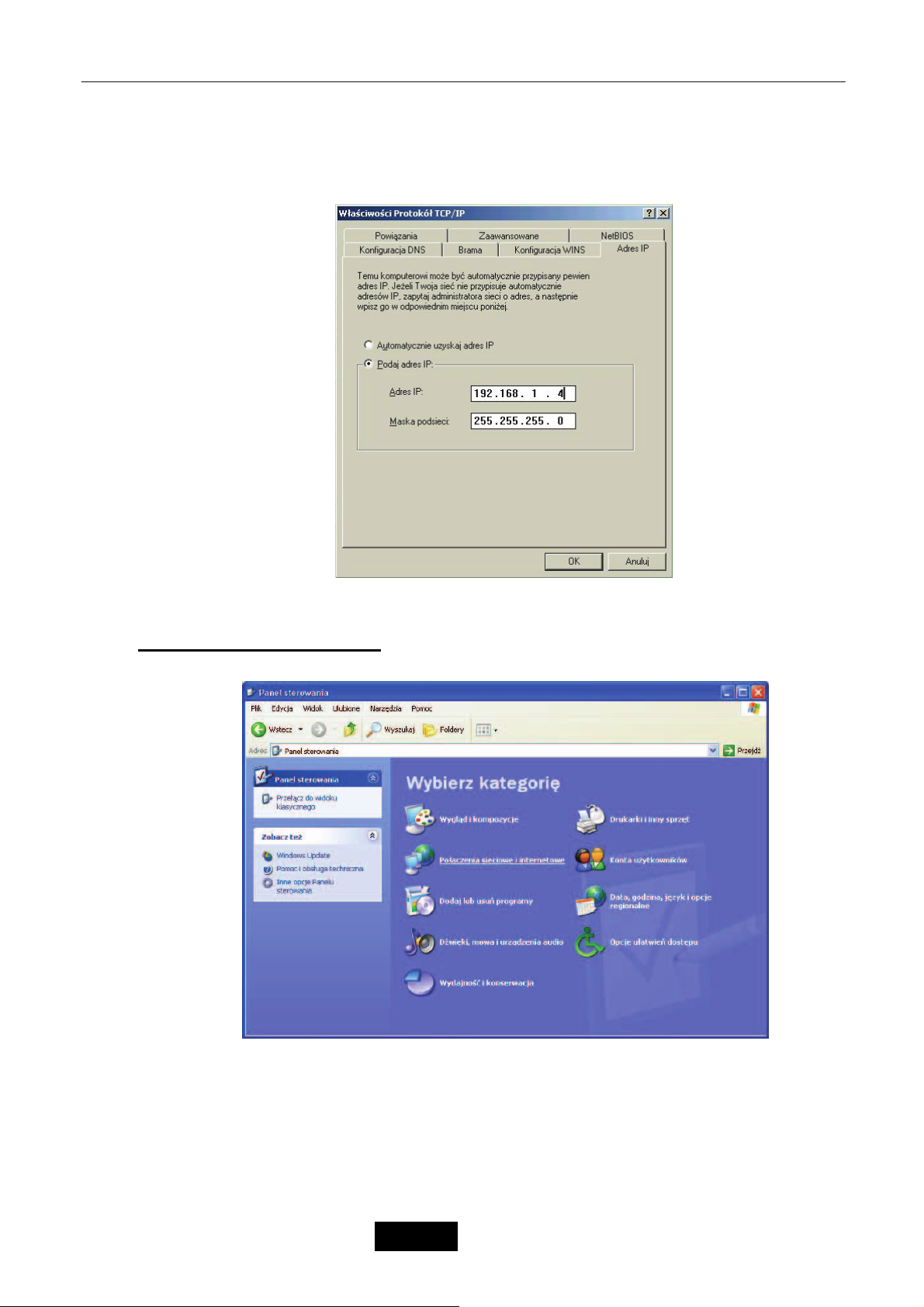
Odstraňování potíží
• Zakładka Adres IP: wybierz Podaj adres IP.
9 Pole Adres IP: wpisz dowolny adres z podsieci urządzenia np. 192.168.1.4
(dowolny, niezajęty adres IP z zakresu 192.168.1.2~192.168.1.254, nie wolno
używać adresu urządzenia 192.168.1.1).
9 Pole Maska podsieci: wpisz wartość 255.255.255.0.
29. Ponownie uruchom system.
dla systemów Windows 2000/XP:
1. Wybierz z Menu Start – Panel sterowania – Połączenia sieciowe i internetowe.
2. Zaznacz połączenie, z którego będziesz korzystał z sieci prawym klawiszem myszy i
wybierz opcje „Właściwości”.
– 5 –
Język Polski
Page 67
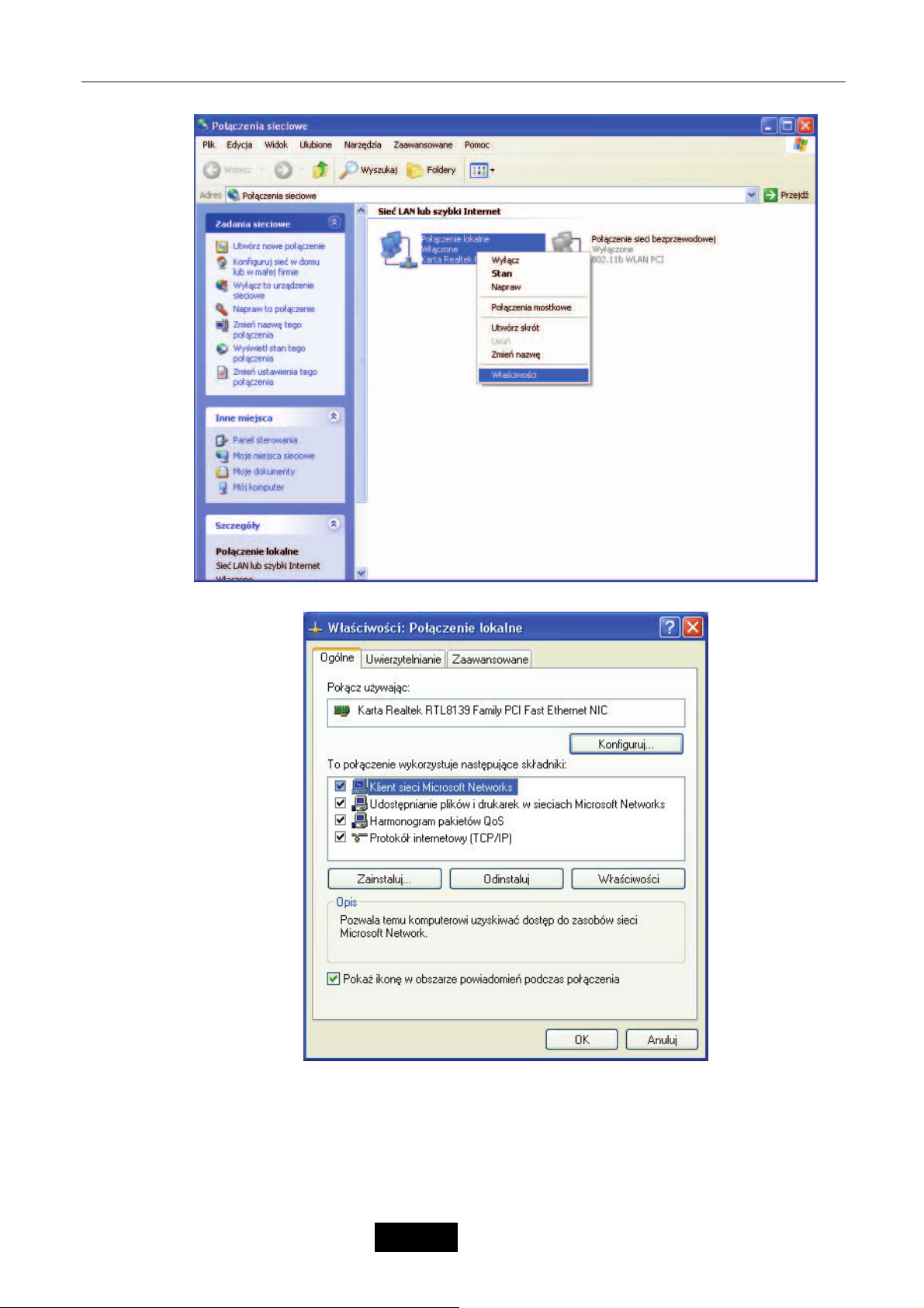
Odstraňování potíží
3. Wybierz z listy opcję „Protokół internetowy (TCP/IP)” i kliknij przycisk „Właściwości”.
4. Wybierz opcję Użyj następującego adresu IP i wprowadź następujące parametry:
9 Pole Adres IP: wpisz dowolny adres z podsieci urządzenia np. 192.168.1.3
(dowolny, niezajęty adres IP z zakresu
wolno używać adresu urządzenia 192.168.1.1).
9 Pole Maska podsieci: wpisz wartość 255.255.255.0.
– 6 –
Język Polski
192.168.1.2~192.168.1.254, nie
Page 68
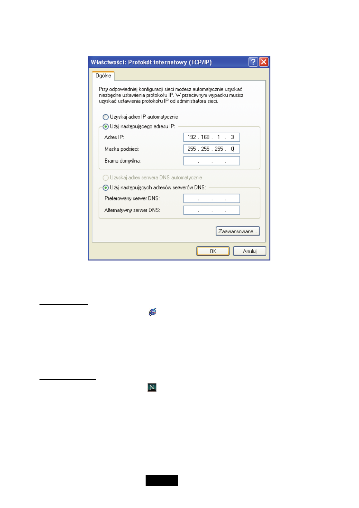
Odstraňování potíží
5. Po kliknięciu przyciksu OK ustawienia zostaną automatycznie zapamiętane.
14.2.1 Konfiguracja przeglądarki Internetowej
Internet Explorer
1. Dwukrotnie kliknij w ikonę
2. Z menu wybierz opcję Narzędzia a następnie Opcje internetowe.
3. Wybierz zakładkę Połączenia. W tabelce Ustawienia połączenia telefonicznego i
wirtualnej sieci prywatnej zaznacz opcję Nigdy nie wybieraj połączenia.
4. Kliknij przycisk Ustawienia sieci LAN i odznacz pole Użyj serwera Proxy dla sieci LAN.
5. Kliknij przycisk OK aby zamknąć okno.
Netscape Navigator
1. Dwukrotnie kliknij w ikonę
2. Z menu wybierz opcję Tools a następnie Options.
3. W zakładce General wybierz opcję Connection Settings.
4. Zaznacz opcję Direct Connection to the Internet.
5. Kliknij przycisk OK aby zamknąć okno
Internet Explorera na pulpicie.
Netscape Navigatora na pulpicie.
14.2.2 Logowanie do urządzenia
6. Włącz przeglądarkę internetową np. Internet Explorer.
7. W polu adres wpisz adres interfejsu LAN urządzenia –
– 7 –
Język Polski
http://192.168.1.1.
Page 69
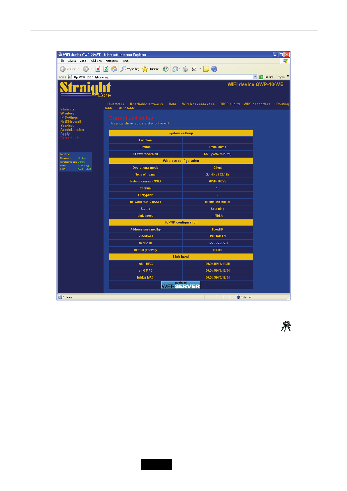
8. Na ekranie zostanie wyświetlone okno strony konfiguracyjnej.
Odstraňování potíží
14.3 Statistics 1
9. Funkcja Unit status z zakładki Statistics jest automatycznie wyświetlana po zalogowaniu się
do urządzenia. Strona konfiguracyjna zawiera dwie ramki oraz górne menu. W lewej ramce
znajduje się lista zakładek, w które pogrupowane są funkcje umieszczone w górnym menu. Prawa
ramka stanowi okno wywoływanej funkcji.
10. Zakładka Statistics umożliwia prezentację statystyk ruchu: tablicę ARP, połączenia
bezprzewodowe, połączenia WDS, statystyka przesyłanych danych i interfejsów. Dodatkowo
umożliwia wyświetlenie listy klientów DHCP oraz dostępnych sieci bezprzewodowych.
14.3.1 Unit Status
Funkcja Unit Status umożliwia wyświetlenia informacji o bieżącym statusie i konfiguracji urządzenia.
Dane pogrupowane są w następujące sekcje: System setings (ustawienia systemowe), Wireless
– 8 –
Język Polski
Page 70

Odstraňování potíží
configuration (konfiguracja sieci bezprzewodowej), TCP/IP configuration (konfiguracja TCP/IP), link level
(adresy MAC).
Tryb Client – Urządzenie łączy się z bezprzewodowym punktem dostępowym AP na podstawie
wspólnej nazwy sieci SSID.
a)
Parametry:
System Settings – Ustawienia systemowe.
Location – Nazwa lokalizacji.
Uptime – Czas pracy urządzenia od ostatniego restartu.
Firmware version – Numer wersji oprogramowania urządzenia (firmware).
Wireless configuration – Konfiguracja modułu bezprzewodowego.
Operational mode – Tryb pracy modułu bezprzewodowego.
Type of usage – Standard transmisji bezprzewodowej.
Network Name - SSID – Nazwa sieci bezprzewodowej SSID.
Chanel – Numer kanały transmisji radiowej.
Encryption – Protokół szyfracji danych.
Network MAC - BSSID – Adres MAC bezprzewodowego punktu dostępowego AP.
Status – Status połączenia bezprzewodowego.
Link speed – Prędkość połączenia bezprzewodowego.
TCP/IP configuration – Konfiguracja protokołu TCP/IP.
Address assigned by – Typ adresacji (stały adres IP, klient DHCP).
IP Address – Adres IP interfejsu Ethernet.
Netmask – Maska podsieci interfejsu Ethernet.
Defaul gateway – Adres IP bramy domyślnej.
Link level – Adresy fizyczne interfejsów.
wlan MAC – Adres MAC interfejsu wlan – bezprzewodowego.
eth0 MAC – Adres MAC interfejsu eth0 – Ethernet.
bridge MAC – Adres MAC interfejsu bridge.
SSID (Service Set Identifier) – jest unikalnym identyfikatorem (nazwą sieci bezprzewodowej), który muszą
dzielić wszyscy klienci bezprzewodowi w ramach wspólnej sieci bezprzewodowej. SSID musi być
identyczny we wszystkich klientach oraz węzłach bezprzewodowych. Dowolna wartość alfanumeryczna do
32 znaków używana do zapobiegania przecięcia komunikacji pomiędzy dwoma (lub więcej) sieciami
WLAN w jednej przestrzeni.
BSSID (Basic Service Set Identifier) – jest identyfikatorem wspólnym dla każdej stacji bezprzewodowej
pracującej w ramach jednego BSS. Wszystkie komputery oraz AP pracujący w tej samej sieci
bezprzewodowej bez roamingu tworzą tak zwany BSS a BSSID jest adresem MAC bezprzewodowego
punktu dostępowego AP (lub stacji bezprzewodowej w przypadku Ad Hoc).
c)
Parametry:
System Settings – Ustawienia systemowe.
Location – Nazwa lokalizacji.
Uptime – Czas pracy urządzenia od ostatniego restartu.
Firmware version – Numer wersji oprogramowania urządzenia (firmware).
Wireless configuration – Konfiguracja modułu bezprzewodowego.
Operational mode – Tryb pracy modułu bezprzewodowego.
Type of usage – Standard transmisji bezprzewodowej.
Network Name - SSID – Nazwa sieci bezprzewodowej SSID.
Chanel – Numer kanały transmisji radiowej.
Encryption – Protokół szyfracji danych.
Network MAC - BSSID – Adres MAC bezprzewodowego punktu dostępowego AP.
– 9 –
Język Polski
Page 71

Odstraňování potíží
Status – Status połączenia bezprzewodowego.
Link speed – Prędkość połączenia bezprzewodowego.
TCP/IP configuration LAN – Konfiguracja protokołu TCP/IP dla interfejsu LAN.
Address assigned by – Typ adresacji (stały adres IP, klient DHCP).
IP Address – Adres IP interfejsu LAN.
Netmask – Maska podsieci interfejsu LAN.
TCP/IP settings of WAN port – Konfiguracja protokołu TCP/IP dla interfejsu WAN.
Address assigned by – Typ adresacji (stały adres IP, klient DHCP, PPPoE, PPTP).
IP Address – Adres IP interfejsu WAN.
Netmask – Maska podsieci interfejsu WAN.
Defaul gateway – Adres IP bramy domyślnej.
Link level – Adresy fizyczne interfejsów.
wlan MAC – Adres MAC interfejsu wlan – bezprzewodowego.
eth0 MAC – Adres MAC interfejsu eth0 – Ethernet.
bridge MAC – Adres MAC interfejsu bridge.
SSID (Service Set Identifier) – jest unikalnym identyfikatorem (nazwą sieci bezprzewodowej), który muszą
dzielić wszyscy klienci bezprzewodowi w ramach wspólnej sieci bezprzewodowej. SSID musi być
identyczny we wszystkich klientach oraz węzłach bezprzewodowych. Dowolna wartość alfanumeryczna do
32 znaków używana do zapobiegania przecięcia komunikacji pomiędzy dwoma (lub więcej) sieciami
WLAN w jednej przestrzeni.
BSSID (Basic Service Set Identifier) – jest identyfikatorem wspólnym dla każdej stacji bezprzewodowej
pracującej w ramach jednego BSS. Wszystkie komputery oraz AP pracujący w tej samej sieci
bezprzewodowej bez roamingu tworzą tak zwany BSS a BSSID jest adresem MAC bezprzewodowego
punktu dostępowego AP (lub stacji bezprzewodowej w przypadku Ad Hoc).
b) Tryb Access Point – Urządzenie łączy się z bezprzewodowym punktem dostępowym AP na
podstawie wspólnej nazwy sieci SSID.
d)
Parametry:
System Settings – Ustawienia systemowe.
Location – Nazwa lokalizacji.
Uptime – Czas pracy urządzenia od ostatniego restartu.
Firmware version – Numer wersji oprogramowania urządzenia (firmware).
Wireless configuration – Konfiguracja modułu bezprzewodowego.
Operational mode – Tryb pracy modułu bezprzewodowego.
Type of usage – Standard transmisji bezprzewodowej.
Network Name - SSID – Nazwa sieci bezprzewodowej SSID.
Chanel – Numer kanały transmisji radiowej.
Encryption – Protokół szyfracji danych.
Network MAC - BSSID – Adres MAC bezprzewodowego punktu dostępowego AP.
Connected clients – Liczba podłączonych klientów bezprzewodowych.
TCP/IP configuration – Konfiguracja protokołu TCP/IP.
Address assigned by – Typ adresacji (stały adres IP, klient DHCP).
IP Address – Adres IP interfejsu Ethernet.
Netmask – Maska podsieci interfejsu Ethernet.
Defaul gateway – Adres IP bramy domyślnej.
Link level – Adresy fizyczne interfejsów.
wlan MAC – Adres MAC interfejsu wlan – bezprzewodowego.
eth0 MAC – Adres MAC interfejsu eth0 – Ethernet.
bridge MAC – Adres MAC interfejsu bridge.
– 10 –
Język Polski
Page 72

Odstraňování potíží
SSID (Service Set Identifier) – jest unikalnym identyfikatorem (nazwą sieci bezprzewodowej), który muszą
dzielić wszyscy klienci bezprzewodowi w ramach wspólnej sieci bezprzewodowej. SSID musi być
identyczny we wszystkich klientach oraz węzłach bezprzewodowych. Dowolna wartość alfanumeryczna do
32 znaków używana do zapobiegania przecięcia komunikacji pomiędzy dwoma (lub więcej) sieciami
WLAN w jednej przestrzeni.
BSSID (Basic Service Set Identifier) – jest identyfikatorem wspólnym dla każdej stacji bezprzewodowej
pracującej w ramach jednego BSS. Wszystkie komputery oraz AP pracujący w tej samej sieci
bezprzewodowej bez roamingu tworzą tak zwany BSS a BSSID jest adresem MAC bezprzewodowego
punktu dostępowego AP (lub stacji bezprzewodowej w przypadku Ad Hoc).
e)
Parametry:
System Settings – Ustawienia systemowe.
Location – Nazwa lokalizacji.
Uptime – Czas pracy urządzenia od ostatniego restartu.
Firmware version – Numer wersji oprogramowania urządzenia (firmware).
Wireless configuration – Konfiguracja modułu bezprzewodowego.
Operational mode – Tryb pracy modułu bezprzewodowego.
Type of usage – Standard transmisji bezprzewodowej.
Network Name - SSID – Nazwa sieci bezprzewodowej SSID.
Chanel – Numer kanały transmisji radiowej.
Encryption – Protokół szyfracji danych.
Network MAC - BSSID – Adres MAC bezprzewodowego punktu dostępowego AP.
Connected clients – Liczba podłączonych klientów bezprzewodowych.
TCP/IP configuration LAN – Konfiguracja protokołu TCP/IP dla interfejsu LAN.
Address assigned by – Typ adresacji (stały adres IP, klient DHCP).
IP Address – Adres IP interfejsu LAN.
Netmask – Maska podsieci interfejsu LAN.
TCP/IP settings of WAN port – Konfiguracja protokołu TCP/IP dla interfejsu WAN.
Address assigned by – Typ adresacji (stały adres IP, klient DHCP, PPPoE, PPTP).
IP Address – Adres IP interfejsu WAN.
Netmask – Maska podsieci interfejsu WAN.
Defaul gateway – Adres IP bramy domyślnej.
Link level – Adresy fizyczne interfejsów.
wlan MAC – Adres MAC interfejsu wlan – bezprzewodowego.
eth0 MAC – Adres MAC interfejsu eth0 – Ethernet.
bridge MAC – Adres MAC interfejsu bridge.
SSID (Service Set Identifier) – jest unikalnym identyfikatorem (nazwą sieci bezprzewodowej), który muszą
dzielić wszyscy klienci bezprzewodowi w ramach wspólnej sieci bezprzewodowej. SSID musi być
identyczny we wszystkich klientach oraz węzłach bezprzewodowych. Dowolna wartość alfanumeryczna do
32 znaków używana do zapobiegania przecięcia komunikacji pomiędzy dwoma (lub więcej) sieciami
WLAN w jednej przestrzeni.
BSSID (Basic Service Set Identifier) – jest identyfikatorem wspólnym dla każdej stacji bezprzewodowej
pracującej w ramach jednego BSS. Wszystkie komputery oraz AP pracujący w tej samej sieci
bezprzewodowej bez roamingu tworzą tak zwany BSS a BSSID jest adresem MAC bezprzewodowego
punktu dostępowego AP (lub stacji bezprzewodowej w przypadku Ad Hoc).
c) Tryb WDS – WDS (Wireless Distribution System) umożliwia komunikację pomiędzy wszystkimi
urządzeniami bezprzewodowymi (klienci) poprzez interfejsy bezprzewodowe
tych dwóch urządzeń.
Parametry:
– 11 –
Język Polski
f)
Page 73

Odstraňování potíží
System Settings – Ustawienia systemowe.
Location – Nazwa lokalizacji.
Uptime – Czas pracy urządzenia od ostatniego restartu.
Firmware version – Numer wersji oprogramowania urządzenia (firmware).
Wireless configuration – Konfiguracja modułu bezprzewodowego.
Operational mode – Tryb pracy modułu bezprzewodowego.
Type of usage – Standard transmisji bezprzewodowej.
Network Name - SSID – Nazwa sieci bezprzewodowej SSID.
Chanel – Numer kanały transmisji radiowej.
Encryption – Protokół szyfracji danych.
Network MAC - BSSID – Adres MAC zdalnego klienta bezprzewodowego.
Status – Status połączenia bezprzewodowego.
Link speed – Prędkość połączenia bezprzewodowego.
TCP/IP configuration – Konfiguracja protokołu TCP/IP.
Address assigned by – Typ adresacji (stały adres IP, klient DHCP).
IP Address – Adres IP interfejsu Ethernet.
Netmask – Maska podsieci interfejsu Ethernet.
Defaul gateway – Adres IP bramy domyślnej.
Link level – Adresy fizyczne interfejsów.
wlan MAC – Adres MAC interfejsu wlan – bezprzewodowego.
eth0 MAC – Adres MAC interfejsu eth0 – Ethernet.
bridge MAC – Adres MAC interfejsu bridge.
SSID (Service Set Identifier) – jest unikalnym identyfikatorem (nazwą sieci bezprzewodowej), który muszą
dzielić wszyscy klienci bezprzewodowi w ramach wspólnej sieci bezprzewodowej. SSID musi być
identyczny we wszystkich klientach oraz węzłach bezprzewodowych. Dowolna wartość alfanumeryczna do
32 znaków używana do zapobiegania przecięcia komunikacji pomiędzy dwoma (lub więcej) sieciami
WLAN w jednej przestrzeni.
BSSID (Basic Service Set Identifier) – jest identyfikatorem wspólnym dla każdej stacji bezprzewodowej
pracującej w ramach jednego BSS. Wszystkie komputery oraz AP pracujący w tej samej sieci
bezprzewodowej bez roamingu tworzą tak zwany BSS a BSSID jest adresem MAC bezprzewodowego
punktu dostępowego AP (lub stacji bezprzewodowej w przypadku Ad Hoc).
d) Tryb Ad Hoc – Urz
ądzenie pracuje w sieci klient-klient bez użycia centralnego punktu
dostępowego AP. Użytkownicy łączą się każdy z każdym bez użycia AP.
Parametry:
System Settings – Ustawienia systemowe.
Location – Nazwa lokalizacji.
Uptime – Czas pracy urządzenia od ostatniego restartu.
Firmware version – Numer wersji oprogramowania urządzenia (firmware).
Wireless configuration – Konfiguracja modułu bezprzewodowego.
Operational mode – Tryb pracy modułu bezprzewodowego.
Type of usage – Standard transmisji bezprzewodowej.
Network Name - SSID – Nazwa sieci bezprzewodowej SSID.
Chanel – Numer kanały transmisji radiowej.
Encryption – Protokół szyfracji danych.
Network MAC - BSSID – Adres MAC zdalnego klienta bezprzewodowego.
Connected clients – Liczba podłączonych klientów bezprzewodowych.
TCP/IP configuration – Konfiguracja protokołu TCP/IP.
Address assigned by – Typ adresacji (stały adres IP, klient DHCP).
IP Address – Adres IP interfejsu Ethernet.
Netmask – Maska podsieci interfejsu Ethernet.
Defaul gateway – Adres IP bramy domyślnej.
Link level – Adresy fizyczne interfejsów.
– 12 –
Język Polski
g)
Page 74

Odstraňování potíží
wlan MAC – Adres MAC interfejsu wlan – bezprzewodowego.
eth0 MAC – Adres MAC interfejsu eth0 – Ethernet.
bridge MAC – Adres MAC interfejsu bridge.
SSID (Service Set Identifier) – jest unikalnym identyfikatorem (nazwą sieci bezprzewodowej), który muszą
dzielić wszyscy klienci bezprzewodowi w ramach wspólnej sieci bezprzewodowej. SSID musi być
identyczny we wszystkich klientach oraz węzłach bezprzewodowych. Dowolna wartość alfanumeryczna do
32 znaków używana do zapobiegania przecięcia komunikacji pomiędzy dwoma (lub więcej) sieciami
WLAN w jednej przestrzeni.
BSSID (Basic Service Set Identifier) – jest identyfikatorem wspólnym dla każdej stacji bezprzewodowej
pracującej w ramach jednego BSS. Wszystkie komputery oraz AP pracujący w tej samej sieci
bezprzewodowej bez roamingu tworzą tak zwany BSS a BSSID jest adresem MAC bezprzewodowego
punktu dostępowego AP (lub stacji bezprzewodowej w przypadku Ad Hoc).
14.3.2 Reachable Networks
2
Funkcja Reachable Networks umożliwia wyświetlenie dostępnych sieci bezprzewodowych.
Dodatkowo gdy urządzenie pracuje w trybie Client umożliwia podłączenie urządzenia do wybranej sieci
bezprzewodowej. W tabelce wyświetlane są parametry dostępnych sieci bezprzewodowych. Aby
podłączyć urządzenie pracujące w trybie Client do sieci bezprzewodowej wybierz ją z listy a następnie
kliknij przycisk Connect. Parametry transmisji zostaną automatycznie ustawione. Jeżeli sieć
bezprzewodowa, do której się łączysz jest zabezpieczona (WEP/WPA) będziesz musiał ustawić parametry
szyfracji za pomocą funkcji Security.
Parametry:
SSID – Nazwa sieci bezprzewodowej SSID.
BSSID – Adres MAC zdalnego klienta bezprzewodowego.
Chanel – Numer kanały transmisji radiowej.
Type – Tryb pracy modułu bezprzewodowego (AP, Ad hoc).
Encryption – Zabezpieczenie sieci bezprzewodowej.
RSSI (Received Signal Strength Indication) – Wskaźnik mocy sygnału odbieranego.
Signal strength – Moc sygnału.
SSID (Service Set Identifier) – jest unikalnym identyfikatorem (nazwą sieci bezprzewodowej), który muszą
dzielić wszyscy klienci bezprzewodowi w ramach wspólnej sieci bezprzewodowej. SSID musi być
identyczny we wszystkich klientach oraz węzłach bezprzewodowych. Dowolna wartość alfanumeryczna do
32 znaków używana do zapobiegania przecię
WLAN w jednej przestrzeni.
BSSID (Basic Service Set Identifier) – jest identyfikatorem wspólnym dla każdej stacji bezprzewodowej
pracującej w ramach jednego BSS. Wszystkie komputery oraz AP pracujący w tej samej sieci
bezprzewodowej bez roamingu tworzą tak zwany BSS a BSSID jest adresem MAC bezprzewodowego
punktu dostępowego AP (lub stacji bezprzewodowej w przypadku Ad Hoc).
cia komunikacji pomiędzy dwoma (lub więcej) sieciami
14.3.3 Data 3
Funkcja Data umożliwia wyświetlenie statystyk wysłanych (Packets transmitted) i odebranych
pakietów (Packets received) na każdym z interfejsów urządzenia.
– 13 –
Język Polski
Page 75

Odstraňování potíží
14.3.4 Wireless Connection 4
Funkcja Wireless connection umożliwia wyświetlenie informacji o aktualnych połączeniach
bezprzewodowych urządzenia, np. gdy urządzenie pracuje w trybie AP, funkcja Wireless connection
umożliwia wyświetlenie informacji o aktualnie podłączonych klientach.
a) Parametry:
MAC Address – Adres MAC zdalnego klienta bezprzewodowego podłączonego do urządzenia.
Description – Opis bezprzewodowego.
RSSI (Received Signal Strength Indication) – Wskaźnik mocy sygnału odbieranego.
Rate – Prędkość transmisji.
Sent – Liczba wysłanych danych w kB.
Received – Liczba odebranych danych w kB.
Dropped – Liczba danych odrzuconych.
Kliknij przycisk Advanced aby uzyskać szczegółowe informacje.
b) Parametry:
MAC Address – Adres MAC zdalnego klienta bezprzewodowego podłączonego do urządzenia.
Description – Opis bezprzewodowego.
RSSI (Received Signal Strength Indication) – Wskaźnik mocy sygnału odbieranego.
Rate – Prędkość transmisji.
Sent – Liczba wysłanych danych w kB.
Received – Liczba odebranych danych w kB.
Dropped – Liczba danych odrzuconych.
Packets sent – Liczba wysłanych pakietów.
Packets received – Liczba odebranych pakietów.
Power save – Tryb zarządzania energią.
Expires in – Czas wygaśnięcia połączenia.
Connetion time – Czas trwa połączenia bezprzewodowego.
14.3.5 DHCP Clients 5
Kiedy serwer DHCP jest aktywny w urządzeniu, funkcja DHCP Clients umożliwia wyświetlenie listy
klientów DHCP – urządzeń, które otrzymały adresy IP z serwera DHCP.
14.3.6 WDS Connection 6
Funkcja WDS Connection umożliwia wyświetlenie listy stacji WDS oraz prezentację statystyk ruchu
do każdej z nich.
14.3.7 Routing Table 7
Funkcja Routing Table umożliwia wyświetlenie aktualnej tablicy routingu. Opcja szczególnie
przydatna w przypadku trybu NAT Router oraz Router.
14.3.8 ARP Table 8
Funkcja ARP Table umożliwia wyświetlenie tablicy ARP, zawierającej adresy MAC urządzeń
podłączonych do ODU zarówno po stronie wireless jak i ethernet.
– 14 –
Język Polski
Page 76
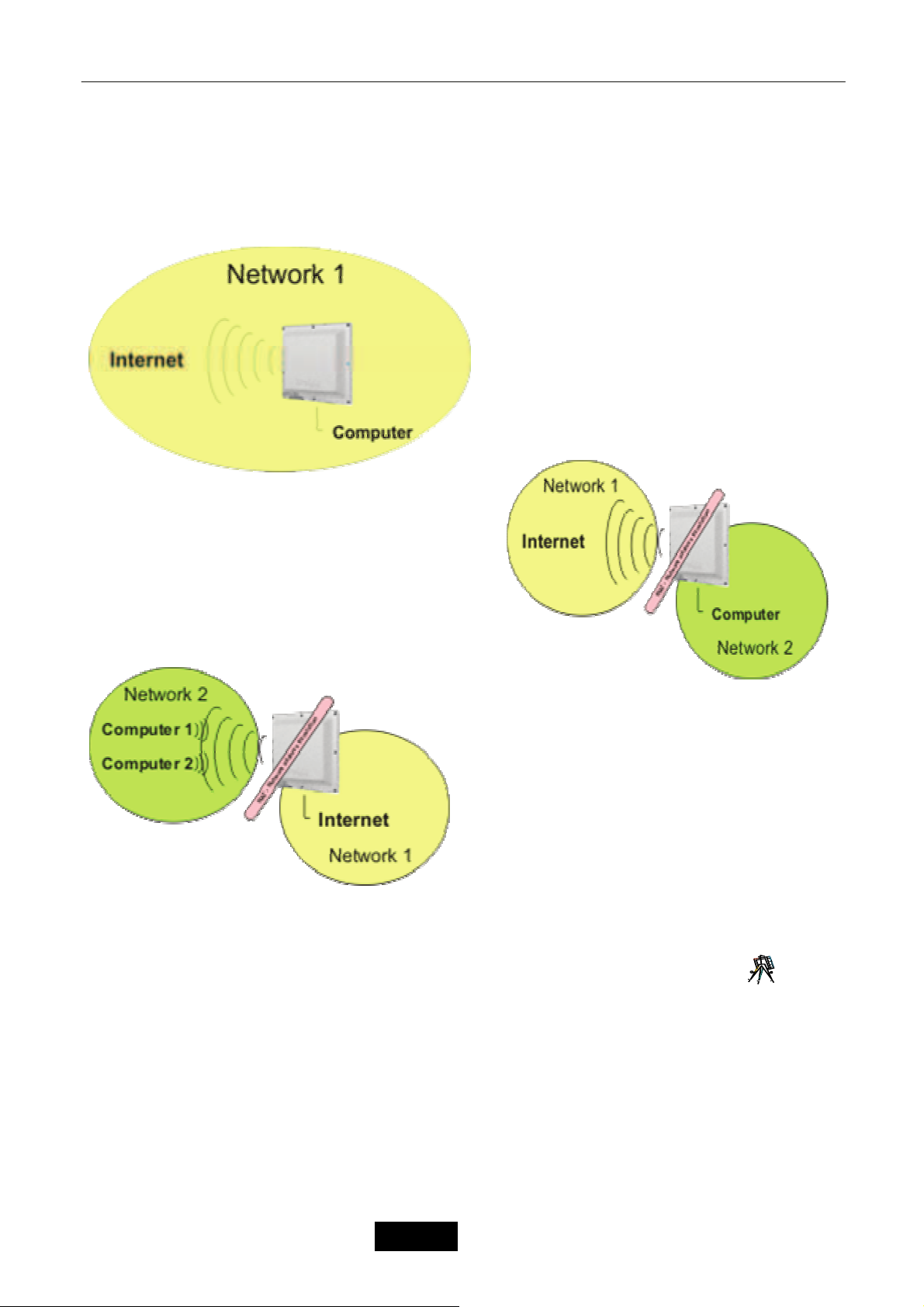
Odstraňování potíží
14.4 Ustawianie trybu pracy
Pierwszym, najważniejszym elementem konfiguracji urządzenia jest określenie trybu jego pracy z
uwzględnieniem routingu. W tym celu należy ustawić tryb pracy urządzenia za pomocą funkcji Routing
mode z zakładki NAT&Firewall. Urządzenie umożliwia ustawienie 3 następujących trybów:
Dymyślnie urządzenie jest ustawione w tryb
Bridge. W trybie tym oba interfejsy (ethernet i
wireless) umieszczone są na tym samym
poziomie, posiadając wspólny adres IP.
Najczęściej w trybie tym urządzenie pracuje jako
AP, w niektórych przypadkach jako client.
Mechanizm NAT jest wyłączony i wszystkie jego
opcje są niedostępne.
Tryb Mode 2 (LAN: eth0 WAN: wlan) jest
najczęściej używany gdy urządzenie pracuje jako client.
Dostęp do Internetu jest realizowany poprzez interfejs
wireless (WAN). Urządzenia podłączone do portu
Ethernet stanowią sieć LAN, w której GWP-106VE
stanowi bramę. W trybie tym przydatny jest wbudowany
serwer DHCP dla użytkowników sieci LAN. PSW-105
może być użyty jako switch sieci LAN.
Tryb Mode 3 (LAN: wlan WAN: eth0) jest
używany gdy urządzenie pracuje jako
bezprzewodowy router dostępowy. interfejs WAN
stanowi port ethernet, do którego może być
podłączony modem DSL, modem kablowy czy stałe
łącze. Użytkownicy sieci LAN łączą się z urządzeniem
bezprzewodowo, które powinno być skonfigurowane
do pracy jako AP.
14.5 Wireless 9
Zakładka Wireless umożliwia pełną konfigurację modułu bezprzewodowego. Za pomocą funkcji
Basic settings użytkownik może ustawić tryb pracy modułu bezprzewodowego wraz z niezbędnymi
parametrami połączenia bezprzewodowego, natomiast za pomocą zakładki Security może ustawić
odpowiedni poziom jego zabezpieczeń. Funkcja Advanced settings umożliwia zaawansowaną konfigurację
parametrów modułu bezprzewodowego takich jak np. moc nadajnika, czułość odbiornika, itp. Funkcja MAC
address filtering umożliwia zdefiniowanie list dostępu dla klientów bezprzewodowych.
– 15 –
Język Polski
Page 77

Odstraňování potíží
Moduł bezprzewodowy tworzy interfejs wireless, który może pracować jako:
Access Point (bezprzewodowy punkt dostępowy AP) – w tym trybie urządzenie stanowi centralny,
bezprzewodowy punkt dostępowy, do którego łączą się inne stacje bezprzewodowe pracujące w trybie
Infrastructure.
Client – w tym trybie urządzenie pracuje jako klient innego AP.
Ad Hoc – w tym trybie urządzenie pracuje w sieci klient-klient bez użycia centralnego punktu
dostępowego. Użytkownicy łączą się każdy z każdym bez AP.
WDS System – często zwany trybem Bridge, jest przeznaczony do połączeń razem dwu („Bridge
Point-to-Point”) lub więcej („Bridge Point-to-Multipoint”) sieci bezprzewodowych
Access Point WDS – jest połączeniem obu powyższych trybów.
Repeater – jest połączeniem trybu Client i AP. Urządzeni jest zarówno Access Pointem jak i klientem
nadrzędnego AP.
Dlaczego tryb WDS System/Bridge jest lepiej dopasowany do połączeń w sieci LAN?
W trybie Bridge urządzenia pracują w pełni przeźroczyście w warstwie drugiej OSI, przez co
nie następuje zamiana adresów MAC w nagłówkach pakietów. Powoduje to, iż sieć staje się
łatwiejsza w zarzą
dzaniu i nie zakłóca pracy niektórych aplikacji (zwłaszcza sieciowych).
14.5.1 Basic Settings: 10
Funkcja Basic Setting umożliwia ustawić tryb pracy modułu bezprzewodowego wraz z niezbędnymi
parametrami połączenia bezprzewodowego. Określa podstawowe parametry transmisji bezprzewodowej.
Aby wyłączyć moduł bezprzewodowy zaznacz opcję Disable RF module.
Parametry:
Type of usage – Standard transmisji bezprzewodowej (2.4 GHz (B), 2.4 GHz (G), 2.4 GHz (B+G)).
Wireless mode – Tryb pracy modułu bezprzewodowego (Client, Access Point, Repeater, WDS
System, Access Point WDS, Ad Hoc).
Network Name - SSID – Nazwa sieci bezprzewodowej SSID.
SSID (Service Set Identifier) – jest unikalnym identyfikatorem (nazwą sieci bezprzewodowej), który
muszą dzielić wszyscy klienci bezprzewodowi w ramach wspólnej sieci bezprzewodowej. SSID musi być
identyczny we wszystkich klientach oraz węzłach bezprzewodowych. Dowolna wartość alfanumeryczna do
32 znaków używana do zapobiegania przecięcia komunikacji pomiędzy dwoma (lub więcej) sieciami
WLAN w jednej przestrzeni.
Chanel – Numer kanału transmisji bezprzewodowej. Dla ETSI dostępne jest 13 kanałów. W
przypadku trybu Client numer kanału jest ustalany automatycznie przez AP z tym samym ESSID.
Zakłócanie i interferencja kanałów.
Aby zmniejszyć zjawisko zakłócania transmisji na różnych kanałach, zaleca się aby
odstęp pomiędzy dwoma kanałami, na których odbywa się transmisja wynosi
Regulation Domain – Zakres kanałów transmisji bezprzewodowej (dla Polski – ETSI).
Connected stations – Kliknij przycisk Display aby wyświetlić okno z listą aktywnych połączeń
bezprzewodowych.
Reachable networks – Kliknij przycisk Display aby wyświetlić okno z dostępnymi sieciami
bezprzewodowymi dla urządzenia pracującego w trybie Client. Wybierz żądaną sieć a następnie kliknij
przycisk Connect. Parametry transmisji zostaną automatycznie ustawione. Jeżeli sieć bezprzewodowa, do
której się łączysz jest zabezpieczona (WEP/WPA) będziesz musiał ustawić parametry szyfracji za pomocą
funkcji Security.
Kliknij przycisk Aplly aby zatwierdzić i zapisać nowe ustawienia. Następnie możesz zakończyć
konfiguracje lub ją kontynuować. Wprowadzone zamiany zostały zapisane.
ł co najmniej 3 kanały.
– 16 –
Język Polski
Page 78

Odstraňování potíží
14.5.2 Advanced Settings 11
Funkcja Advanced Setting umożliwia określenie zaawansowanych parametrów transmisji
bezprzewodowej. Najczęściej nie będziesz musiał zmieniać tych parametrów. Użytkownikom mniej
zaawansowanym nie zaleca się zmiany poniższych parametrów.
Parametry:
Authentication type – Typ autentykacji WEP.
Open system – nadawca i odbiorca nie dzielą klucza dla komunikacji. Każdy generuje swoją własną
parę kluczy, która następnie jest akceptowana przez innych. Podczas każdego ustanowienia połączenia
klucze są renegocjowane.
Preshared key – nadawca i odbiorca dzielą wspólny klucz dla komunikacji, który jest używany dla
długiego odcinka czasu.
Auto – Automatyczna detekcja.
Fragment level – Parametr ten definiuje próg powyżej, którego pakiety będą fragmentowane. Jeżeli
cześć fragmentów danych ulegnie kolizji to tylko te fragmenty zostaną ponownie wysłane i nie jest
konieczne ponowne wysyłanie wszystkich fragmentów.
RTS level – Kiedy rozmiar pakietu jest mniejszy niż RTS level, AP nie będzie wykorzystywał
mechanizmu RTS/CTS do wysyłania pakietów, używanego w celu unikania kolizji danych w sieciach
bezprzewodowych LAN.
Interval of Beacon packet – Opcja określa przedział czasu co jaki będą wysyłane informacje o sieci
(Beacon Frames).
Link Speed – Parametr okre
DTIM Period – DTIM (Delivery Traffic Indication Message) jest częścią pakietu beacon używaną do
powiadamiania urządzeń pracujących w trybie oszczędzania energii o przychodzącej transmisji danych.
Zwiększenie wartości powoduje wydłużenie czasu przejścia z trybu oszczędzania energii do trybu pracy.
Preamble type – Typ preambuły. Preambuła jest pierwszym polem PPDU, które jest przydzielane
ramce przy transmisji do warstwy fizycznej, określającym długość bloku CRC. Możliwe są dwa jej formaty:
krótka (short) lub długa (long). Krótka preambuła zwiększa wydajność a długa zwiększa niezawodność.
Hide SSID – Opcja umożliwiająca wyłączenie (Enabled) rozgłaszania SSID poprzez AP co zwiększa
poziom bezpieczeństwa.
IAPP Function – Protokół IAPP (Inter-Access Point Protocol) używany jest w roamingu. AP
automatycznie rozsyła informacje o aktualnie podłączonych klientach do swoich sąsiadów. Je
więcej niż jednego AP w swojej sieci bezprzewodowej LAN oraz klienci wymagają roamingu możesz
uaktywnić tą opcję w przeciwnym wypadku zaleca się wyłączenie jej, co zwiększa poziom bezpieczeństwa.
802.11g Protection – Opcja używana do zmniejszenia liczby kolizji pakietów i zwiększenia
wydajności w sieciach bezprzewodowych złożonych zarówno z urządzeń standardu 802.11b
(wykorzystujących modulacje CCK) jak i 802.11g (wykorzystujących modulacje OFDM). Często nazywana
jest CTS Protection. Przy włączonej opcji spada przepustowość AP.
Wireless Client Isolation – Funkcja aktywna tylko w trybie pracy AP, blokująca komunikację
pomiędzy klientami bezprzewodowymi podłączonymi do tego AP.
802.11b Output Power – Parametr określający moc nadajnika w standardzie 802.11b z modulacją
CCK. Zanim skonfigurujesz moc nadajnika sprawdź dopuszczalną moc w Twoim regionie.
802.11g Output Power – Parametr określający moc nadajnika w standardzie 802.11g z modulacją
OFDM. Zanim skonfigurujesz moc nadajnika sprawdź dopuszczalną moc w Twoim regionie.
Input amplifier gain – Czułość przedwzmacniacza odbieranego sygnału. Za duża wartość
spowodować wzmocnienie zakłóceń, wzrost błędnej transmisji, nakładanie się sygnałów.
Kliknij przycisk Save aby zatwierdzić i zapisać nowe ustawienia. Następnie możesz zakończyć
konfiguracje lub ją kontynuować. Wprowadzone zamiany zostały zapisane.
śla maksymalną prędkość transmisji danych.
żeli używasz
może
14.5.3 Security 12
Funkcja Security umożliwia konfigurację zabezpieczeń połączenia bezprzewodowego. Urządzenie
wspiera mechanizmy: WEP, IEEE 802.11x, IEEE 802.11x z WEP, WPA z współdzielonym kluczem (pre-
– 17 –
Język Polski
Page 79

Odstraňování potíží
shared key) oraz WPA z autentykacją za pomocą serwera RADIUS. Zabezpieczenia te pomagają uchronić
sieć bezprzewodową przed nieautoryzowanym dostępem.
Połączenie może być szyfrowane za pomocą protokołu WEP lub algorytmów TKIP (WPA) i AES
(WPA2). Sam standard 802.11x umożliwia tylko autentykację użytkownika przez serwer RADIUS,
użytkownik aby móc się zalogować do Access Pointa musi podać prawidłowy login i hasło. W 802.11x
dane nie są szyfrowane.
Uwaga: W trybie Access Point WDS, zabezpieczenia dotyczą tylko modułu Access Point.
Parametry:
Encryption – Wybór zabezpieczenia: WEP Encryption, WPA (TKIP), WPA2 (AES).
Use 802.1x authentication – Opcja umożliwia stworzeniu wirtualnego portu dla komunikacji
użytkownika autoryzowanego przez serwer Radius za pomocą 802.1x. Pole TCP/IP Port – określa port
serwera Radius, IP address – jego adres IP a Password – hasło.
Enable pre-authorization – Opcja pre-autoryzacji dostępna tylko dla WPA2.
14.5.3.1 WEP Encryption 13
WEP (Wired Equivalent Privacy) jest mechanizmem ochrony przesyłanych danych siecią
bezprzewodową określonym poprzez standard IEEE 802.11, który zwiększa zaufanie przesyłanych
danych i jest ekwiwalentny do przewodowych sieci LAN nie używających technik kryptografii. WEP używa
algorytmów 64, 128 bitowego klucza współdzielonego.
Parametry:
Key length – Długość klucza WEP: 64 bit lub 128 bit. Dłuższy klucz zwiększa poziom
bezpieczeństwa ale obniża przepustowość.
Format of key – Format klucza: alfanumeryczny ASCII lub heksadecymalny HEX (0-9, a-f lub A-F).
Prefered key – Wybór jednego z czterech kluczy.
Encryption key 1–4 – Wartość klucza szyfrującego.
Dla 64 bit: ASCII – 5 znaków ASCII, HEX – 10 znaków (0-9, a-f lub A-F).
Dla 128 bit: ASCII – 13 znaków ASCII, HEX – 26 znaków (0-9, a-f lub A-F).
Use 802.1x authentication – Opcja umożliwia stworzeniu wirtualnego portu dla komunikacji
użytkownika autoryzowanego przez serwer Radius za pomocą 802.1x. Pole TCP/IP Port – określa port
serwera Radius, IP address – jego adres IP a Password – hasło.
Kliknij przycisk Save aby zatwierdzić i zapisać nowe ustawienia. Następnie możesz zakończyć
konfiguracje lub ją kontynuować. Wprowadzone zamiany zostały zapisane.
14.5.3.2 WPA/WPA2 14
WPA (WiFi Protected Access) oraz WPA2 jest bardziej bezpiecznym mechanizmem zabezpieczania
sieci bezprzewodowej opartym na współdzielonym kluczu (Pre-shared key) lub autentykacji za pomocą
serwera RADIUS. Współdzielony klucz jest używany do autoryzacji stacji oraz szyfracji przesyłanych
danych. WPA wykorzystuje do szyfrowania danych algorytm TKIP, natomiast WPA2 algorytm AES.
Parametry:
Use 802.1x authentication – Opcja umożliwia stworzeniu wirtualnego portu dla komunikacji
użytkownika autoryzowanego przez serwer Radius za pomocą 802.1x. Pole TCP/IP Port – określa port
serwera Radius, IP address – jego adres IP a Password – hasło.
Auth Mode – Tryb autoryzacji: Radius server – za pomocą serwera Radius lub Shared Key – za
pomocą symetrycznego klucza współdzielonego.
Key format – Format klucza symetrycznego: alfanumeryczny ASCII lub heksadecymalny Hex (0-9, af lub A-F). Minimum 8 znaków ASCII lub 64 znakowa wartość heksadecymalna.
Prefered key – Wybór jednego z czterech kluczy.
Encryption key 1–4 – Wartość klucza szyfrującego.
Dla 64 bit: ASCII – 5 znaków ASCII, HEX – 10 znaków (0-9, a-f lub A-F).
– 18 –
Język Polski
Page 80

Odstraňování potíží
Dla 128 bit: ASCII – 13 znaków ASCII, HEX – 26 znaków (0-9, a-f lub A-F).
Kliknij przycisk Save aby zatwierdzić i zapisać nowe ustawienia. Następnie możesz zakończyć
konfiguracje lub ją kontynuować. Wprowadzone zamiany zostały zapisane.
14.5.4 MAC address filtering 15
Funkcja MAC addres filtering umożliwia określenie listy użytkowników sieci bezprzewodowej na
podstawie ich MAC adresów, którzy będą posiadali dostęp do urządzenia lub dostęp będzie zabroniony.
Parametry:
MAC address filter – Disabled – Filtrowanie wyłączone.
Accept Listed – Lista dopuszczonych użytkowników. Jeżeli adres MAC nie został dodany do listy,
dostęp połączenia dla niego jest blokowany.
Deny Listed – Lista zabronionych użytkowników. Jeżeli adres MAC znajduje się na liście, dostęp
połączenia dla niego jest blokowany. Wszyscy pozostali spoza listy będą posiadali dostęp do urządzenia.
MAC address – Adres MAC klienta bezprzewodowego dodawany do listy.
Desciption – Komentarz.
Najczęściej za pomocą funkcji Mac address filtering tworzy się listę dostępu, czyli listę adresów MAC
klientów bezprzewodowych, którzy będą posiadali dostęp do urządzenia. W tym celu ustaw opcję MAC
address filter na Accept listed i dodaj kolejno adresy MAC klientów bezprzewodowych do tabeli List of
stations, wpisując adres MAC każdego klienta w polu MAC address, komentarz w polu Description a
następnie klikając przycisk Add.
Aby usunąć MAC adres z listy List of stations zaznacz go a nast
Jeżeli chcesz wyczyścić całą listę kliknij prawy przycisk Remove.
Kliknij przycisk Aplly aby zatwierdzić i zapisać nowe ustawienia. Następnie możesz zakończyć
konfiguracje lub ją kontynuować. Wprowadzone zamiany zostały zapisane.
ępnie kliknij lewy przycisk Remove.
14.5.5 WDS System
Funkcja WDS/Bridge system setup umożliwia określenie listy stacji WDS, urządzenia pracującego w
trybie WDS System lub WDS Access Point. WDS (Wireless Distribution System) umożliwia komunikację
pomiędzy wszystkimi urządzeniami bezprzewodowymi (klienci) poprzez interfejsy bezprzewodowe tych
dwóch urządzeń.
a)
Parametry:
Encryption – Zabezpieczenie sieci bezprzewodowej.
Disabled – Sieć niezabezpieczona.
WEP 64bit / WEP 128bit – Protokół WEP z 64 lub 128 bitowym kluczem określonym w polach WEP
key format (format klucza: ASCII lub Hex) oraz WEP Key (wartość klucza).
b)
WPA (TKIP) / WPA2 (AES) – Protokół TKIP lub AES z kluczem symetrycznym określonym w polach
Fromat of shared key (format klucza: ASCII lub Hex) oraz Preshared Key (wartość klucza).
c)
MAC address – W trybie WDS System musisz zdefiniować adresy MAC wszystkich urządzeń
tworzących strukturę WDS.
Desciption – Komentarz.
– 19 –
Język Polski
Page 81

Odstraňování potíží
Przykład: Aby połączyć dwa urządzenia w strukturę WDS należy ustawić urządzenia w tryb WDS
System (lub Access Point WDS) oraz na każdym z urządzeń dodać za pomocą funkcji WDS System adres
MAC drugiego urządzenia wraz z określeniem zabezpieczenia połączenia bezprzewodowego.
d)
14.6 IP Settings 16
Zakładka IP Settings umożliwia zdefiniowanie parametrów protokołu TCP/IP.
a) dla trybu Bridge:
b) dla trybu NAT Router:
14.6.1 IP Settings for LAN / IP Settings for management
Funkcja IP Settings for LAN (IP Settings for management) umożliwia określenie parametrów
protokołu TCP/IP interfejsu LAN, który w przypadku trybu Bridge stanowi zarówno interfejs ethernet jak i
wireless. W przypadku trybu pracy NAT Router oraz Router stanowi jeden z tych interfejsów. Interfejs LAN
może posiadać na stałe przypisany adres IP lub będąc klientem DHCP otrzymywać go z serwera DHCP
umieszczonego w sieci LAN.
a)
Parametry:
IP Address – Adres IP interfejsu LAN.
Subnet mask – Maska podsieci interfejsu LAN.
DHCP Mode – Tryb pracy interfejsu LAN:
DHCP Disabled – Wyłączony serwer DHCP, urządzenie musi posiadać na stałe przypisany adres IP
w polu IP Address oraz maskę podsieci w polu Subnet mask.
DHCP Client – Wyłączony serwer DHCP, urządzenie pracuje jako klient DHCP, otrzymuje adres IP i
maskę podsieci z serwera DHCP umieszczonego w sieci LAN.
DHCP Server – Włączony serwer DHCP, urządzenie musi posiadać na stałe przypisany adres IP w
polu IP Address oraz maskę podsieci w polu Subnet mask. Zakres puli adresowej serwera DHCP
można określić w polach DHCP address range. Aby wyświetlić listę klientów DHCP klikni przycisk
Show.
DHCP Relay – Zapytania DHCP zostaną przekazane do innego serwera DHCP umieszczonego w
sieci WAN.
802.1d protocol (spanning tree) – Włączenie opcji Spanning Tree, zapobiegającej powstaniu pętli w
sieci.
Clone MAC address – Klonowanie MAC adresu interfejsu LAN.
14.6.2 IP Settings for WAN
Funkcja IP Settings for WAN umożliwia określenie parametrów protokołu TCP/IP interfejsu WAN,
która nie jest dostępna w przypadku trybu Bridge. Interfejs WAN musi posiadać adres IP z maską podsieci.
Interfejs WAN może być skonfigurowany ze statycznym adresem IP lub dynamicznym jako klient DHCP,
klient PPPoE lub klient PPTP.
– 20 –
Język Polski
Page 82

Odstraňování potíží
14.6.2.1 Fixed IP Address
Opcja Fixed IP Address umożliwia przypisanie stałego adresu IP interfejsowi WAN w polu IP
Address, maski podsieci w polu Subnet mask oraz adresów serwerów DNS w polach DNS server 1 –
DNS server 3. Opcja Clone MAC address umożliwia sklonowanie MAC adresu na interfejsie WAN.
b)
14.6.2.2 DHCP Client
Opcja DHCP Client umożliwia skonfigurowanie interfejsu WAN jako klienta DHCP. Urządzenie
otrzyma adres IP, maskę podsieci oraz adresy serwerów DNS z serwera DHCP umieszczonego w sieci
WAN. Adresy serwerów DNS można zdefiniować w polach DNS server 1 – DNS server 3 zaznaczając
wcześniej opcję manually lub manually+relay w polu Set DNS. Opcja Clone MAC address umożliwia
sklonowanie MAC adresu na interfejsie WAN.
c)
14.6.2.3 PPPoE
Opcja PPPoE umożliwia skonfigurowanie interfejsu WAN jako klienta PPPoE. Urządzenie otrzyma
adres IP, maskę podsieci oraz adresy serwerów DNS z serwera PPPoE umieszczonego w sieci WAN.
Adresy serwerów DNS można zdefiniować w polach DNS server 1 – DNS server zaznaczając wcześniej
opcję manually lub manually+relay w polu Set DNS. Połączenie z serwerem PPPoE jest autoryzowane na
podstawie nazwy użytkownika (pole User name) oraz hasła (pole Password) i może trwać ciągle
(Connection Type równe Permanent), być zestawiane na żądanie (opcja On demand) lub zarządzane
ręcznie (opcja Manual) za pomocą przycisków Connect i Disconnect. W przypadku połączenia na żądanie
można określić czas bezczynności (opcja Disconnect after), po którym połączenie zostanie automatycznie
rozłączone. Parametr MTU Size (Maximum Transmission Unit) – określa maksymalny rozmiar pakietu,
który może zostać wysłany połączeniem PPPoE (ustala ISP). Opcja Clone MAC address umożliwia
sklonowanie MAC adresu na interfejsie WAN.
Opcja Require MPPE (Microsoft Poin-to-Point Encryption) umożliwia włączenie szyfrowania
połączenia za pomocą protokołu MPPE przy użyciu klucza 40 bit lub 128 bit.
d)
14.6.2.4 PPTP
Opcja PPTP umożliwia skonfigurowanie interfejsu WAN do pracy jako klient PPTP. Urządzenie
zostanie połączone z serwerem ISP bezpiecznym tunelem PPTP. Połączenie z serwerem PPTP (adres
serwera w polu Server IP address) jest zestawiane na podstawie nazwy użytkownika (pole User name) i
hasła (pole Password). W polach IP Address oraz Subnet mask należy określić adres IP i maskę podsieci
interfejsu WAN.
Dodatkowo można określić rodzaj szyfracji w polach MPPE (Microsoft Poin-to-Point Encryption) oraz
MSCHAP (Microsoft CHAP). Opcja Require MPPE umożliwia włączenie szyfrowania połączenia za
pomocą protokołu MPPE przy użyciu klucza 40 bit lub 128 bit. Opcja Require MSCHAP umożliwia
wykorzystanie protokołu autoryzacji CHAP (Challenge-Handshake Authentication Protocol) używającego
do autoryzacji połączenia nazwy użytkownika, hasła oraz kombinacji losowo wygenerowanego łańcucha
przy użyciu funkcji haszującej.
Parametr MTU Size (Maximum Transmission Unit) – określa maksymalny rozmiar pakietu, który
może zostać wysłany połączeniem PPTP. Opcja Clone MAC address umożliwia sklonowanie MAC adresu
na interfejsie WAN.
– 21 –
Język Polski
Page 83

Odstraňování potíží
e)
14.6.2.5 PPTP+DHCP
Opcja PPTP+DHCP umożliwia skonfigurowanie interfejsu WAN do pracy jako klient DHCP z
wykorzystaniem połączenia PPTP. Konfiguracja analogiczna do opcji PPTP.
f)
14.6.3 Gateway and Routing 17
Funkcja Gateway and routing umożliwia konfiguracje statycznej tablicy routingu w trybie pracy NAT
Router oraz Router. Za pomocą opcji Default gateway należy zdefiniować bramę domyślna dla interfejsu
WAN.
a) c)
Parametry:
Destination IP – Adres sieci docelowej.
Mask – Maska podsieci docelowej.
Gateway – Brama dla sieci określonej w polach Destination IP oraz Mask.
14.7 Nat&Firewall
Zakładka Nat&Firewall umożliwia określenie trybu pracy urządzenia jako: Bridge lub jako NAT
Router. W trybie Bridge urządzenie posiada jeden wspólny adres IP dla interfejsu Ethernet i Wireless. W
trybie NAT Router oraz Router urządzenie posiada oddzielny adres IP dla interfejsu Ethernet i oddzielny
dla interfejsu Wireless. Użytkownik sam decyduje czy interfejsem LAN ma być Ethernet czy Wireless. To
damo dotyczy interfejsu WAN. Za pomocą mechanizmu NAT wszyscy użytkownicy sieci LAN mogą dzielić
wspólnie jeden fizyczny adres IP interfejsu WAN. Aby ustawić tryb Router z wyłączonym mechanizmem
NAT zaznacz opcję Disable network address translation (NAT).
a) Tryb NAT Router:
2. LAN: eth0 – Interfejsem LAN jest interfejs Ethernet.
WAN: wlan – Interfejsem WAN jest interfejs Wireless.
3. LAN: wlan – Interfejsem LAN jest interfejs Wireless.
WAN: eth0 – Interfejsem WAN jest interfejs Ethernet.
14.7.1 IP Address filtering
Funkcja IP Address filtering umożliwia ograniczenie ruchu pochodzącego z sieci lokalnej na
podstawie adresu IP użytkownika sieci LAN. Stosowana tylko w trybie pracy NAT Router blokuje dostęp do
sieci Internet (interfejsu WAN) użytkownikom sieci LAN o zdefiniowanych adresach IP.
d)
Przykład: Zablokowanie dostępu do sieci WAN wewnętrznemu serwerowi wymiany plików o adresie
IP 192.168.1.4.
– 22 –
Język Polski
e)
Page 84

Odstraňování potíží
14.7.2 MAC Address filtering 18
Funkcja MAC address blocking umożliwia ograniczenie ruchu pochodzącego z sieci lokalnej na
podstawie adresu fizycznego MAC użytkownika sieci LAN. Stosowana tylko w trybie pracy NAT Router
blokuje dostęp do sieci Internet (interfejsu WAN) użytkownikom sieci LAN o zdefiniowanych adresach
MAC.
Przykład: Zablokowanie dostępu do sieci WAN użytkownikowi o adresie fizycznym MAC
22:fd:43:a5:12:35.
b)
14.7.3 Port filtering 19
Funkcja TCP/IP port blocking umożliwia ograniczenie ruchu pochodzącego z sieci lokalnej na
określonych portach TCP/UDP. Stosowana tylko w trybie pracy NAT Router blokuje dostęp do sieci
Internet (interfejsu WAN) wszystkim użytkownikom sieci LAN na zdefiniowanych portach TCP/UDP.
Przykład: Zablokowanie dostępu do sieci WAN na portach TCP/UDP powyżej 1023 (1024 – 65535).
14.7.4 Port Forwarding
Funkcja Port Forwarding umożliwia mapowanie portów interfejsu WAN urządzenia pracującego w
trybie pracy NAT Router z aktywnym mechanizmem NAT na określony host w sieci LAN. Wszystkie porty
TCP i UDP od strony interfejsu WAN są zamknięte dzięki mechanizmowi NAT. Jeżeli jakiś określony host
w lokalnej sieci LAN potrzebuje zmapowania portu TCP/UDP od strony WAN należy dodać odpowiedni
wpis.
Zastosowanie: Najczęściej funkcję Port Forwarding wykorzystuje się celem udostępnienia lokalnego
serwera www, ftp, serwer gry użytkownikom sieci WAN. Również aby móc korzystać z programów p2p
(peer-to-peer) z pełną przepustowością (High ID) lub aplikacji multimedialnych należy przekierować
określony port/porty.
Uwaga: Dany port można przekierować TYLKO dla jednego adresu IP. Jeżeli zostanie
przekierowany port TCP 80 dla adresu 192.168.2.10 to nie można przekierować portu 80 dla żadnego
innego adresu w sieci LAN.
Przykład: Udostępnienie serwera www znajdującego się w sieci LAN na komputerze o adresie IP
192.168.1.55. Interfejs WAN posiada adres IP 83.80.80.2.
1. Należy dodać przekierowanie dla portu TCP 80 (www) dla adresu 192.168.1.55.
2. Zapisaniu ustawień i restarcie urz
dla użytkowników sieci LAN –
dla użytkowników sieci WAN –
ądzenia serwer będzie widoczny pod następującymi adresami:
http://192.168.1.55
http://83.80.80.2
14.7.5 IP/MAC Address/Port filtering, Port forwarding
Aby dodać wpis i uaktywnić funkcję zaznacz opcje Enable nazwa_funkcji wpisz wartości we
wszystkich polach i kliknij przycisk Add. Klikając przycisk Cancel anulujesz wprowadzone dane. Dane
zostaną dodane do tabelki poniżej.
– 23 –
Język Polski
Page 85
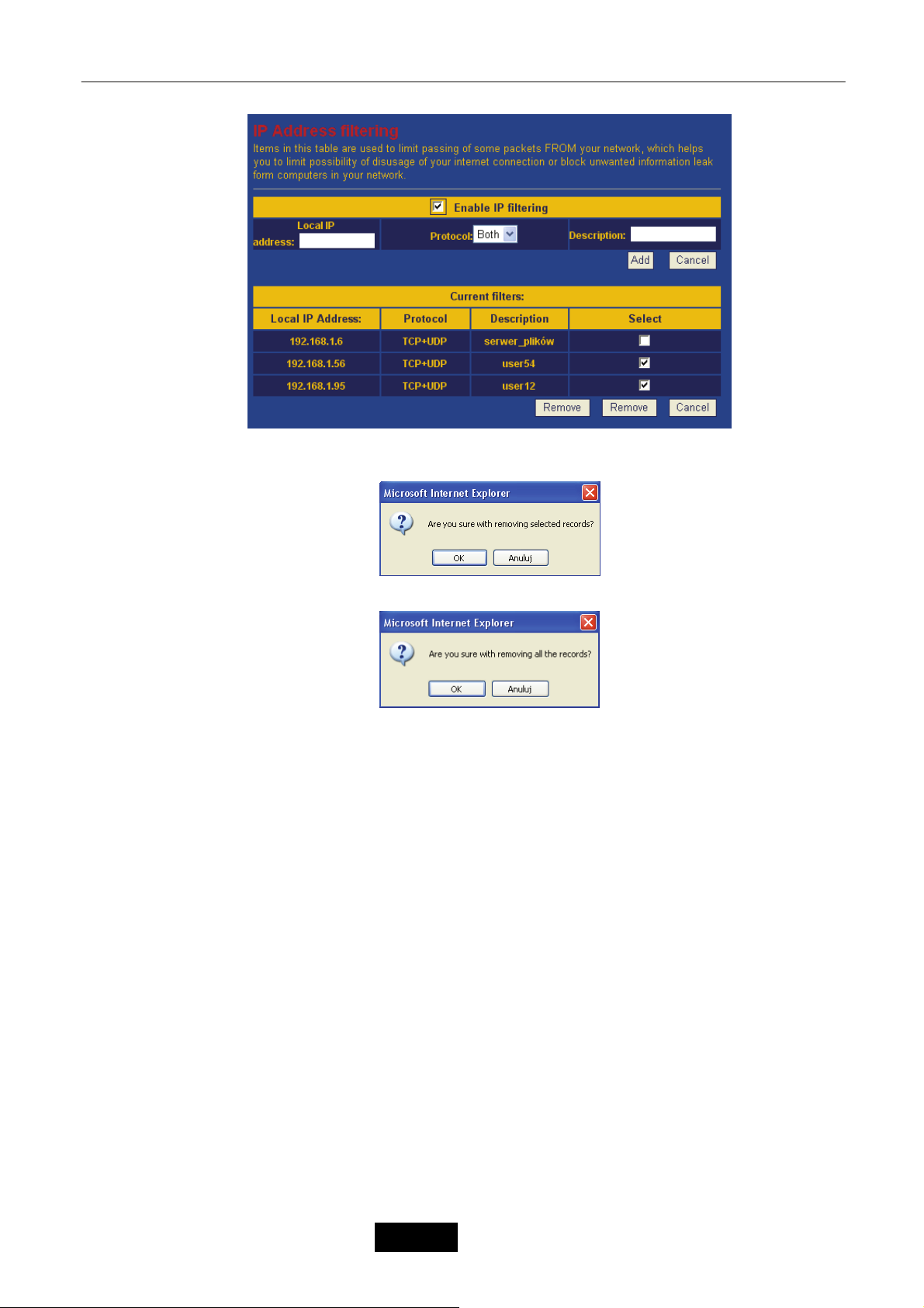
Odstraňování potíží
Aby usunąć wybrany wpis/wpisy zaznacz je w polu Select a następnie kliknij lewy przycisk Remove.
Zostanie wyświetlony poniższy monit.
Kliknij OK aby usunąć zaznaczone wpisy lub Anuluj aby anulować usunięcie. Aby usunąć wszystkie
wpisy kliknij prawy przycisk Remove. Na ekranie zostanie wyświetlony poniższy monit.
Kliknij OK aby wyczyścić tablicę lub Anuluj aby anulować usuwanie.
14.7.6 DMZ Settings
DMZ (Demilitarized Zone) jest obszarem pomiędzy chronioną za pomocą NAT siecią LAN a siecią
WAN. Umożliwia ona wystawienie hosta z sieci LAN do sieci WAN pod adresem interfejsu WAN
urządzenia pracującego w trybie NAT Router. Host będzie widoczny w sieci LAN pod jego adresem IP w
sieci LAN natomiast w sieci WAN pod adresem interfejsu WAN urządzenia. W praktyce oznacza to
przekierowanie całego zakresu portów (1 – 65535)..
Przykład: Pod adresem WAN urządzenia w sieci Internet widoczny będzie host z sieci lokalnej o
adresie IP 192.168.1.69.
14.8 Services
Zakładka Services umożliwia zarządzanie usługami urządzenia takimi jak: ograniczenie prędkości
interfejsów (Rate control), konfiguracja klienta DDNS (Dynamic DNS), konfiguracja klienta NTP (NTP
Services), Watchdog/Restart, diagnostyka łącza (Network tests).
– 24 –
Język Polski
Page 86

Odstraňování potíží
14.8.1 Rate control 20
Funkcja Rate control settings umożliwia ograniczenie przepustowości interfejsu do określonej
wartości.
Aby uaktywnić funkcję Rate control zaznacz opcję Enable rate control a następnie wybierz limity z
rozwijanego menu Limit for Upload oraz Limit for Download. Następnie kliknij przycisk Save.
14.8.2 Dynamic DNS 21
Funkcja Dynamic DNS Settings umożliwia skonfigurowanie klienta DDNS. DDNS (Dynamic Domain
Name System) umożliwia tłumaczenie nazwy domenowej urządzenia na jego aktualny publiczny adres IP,
istotne zwłaszcza przy dynamicznym adresie IP. Umożliwia to łatwy dostęp do usług udostępnionych na
serwerach wirtualnych czy DMZ urządzenia pracującego z dynamicznym adresem IP. Urządzenie wpiera
dwóch dostawców: dyndns oraz TZO. Aby możliwe było korzystanie z usługi serwera DDNS użytkownik
musi wcześniej posiadać na nim swoje indywidualne konto oraz zarejestrować swoją nazwę hosta. TZO
udostępnia darmową 30 dniową wersję usługi, dyndns obecnie jest darmowe.
Parametry:
Service provider – Nazwa dostawcy DDNS.
Domain name – Nazwa domenowa urządzenia.
User (name/email) – Nazwa użytkownika zarejestrowana u dostawcy DDNS.
Password (key) – Hasło użytkownika zarejestrowane u dostawcy DDNS.
Przykład: Konfiguracja klienta DDNS dla dyndns.org.
b)
14.8.3 NTP Service 22
Funkcja Time synchronization umożliwia konfigurację synchronizacji czasu z serwerem NTP. NTP
(Network Time Protocol) – jest protokołem za pomocą, którego urządzenie otrzymuje aktualny czas
(godzina, data) z serwera czasu umieszczonego w Internecie.
Parametry:
Current time – Bieżąca data i czas.
Timezone – Strefa czasowa w odniesieniu do GMT.
Active time synchronization – Aktywacja automatycznej synchronizacji z serwerem NTP.
NTP server – Nazwa serwera NTP.
Server IP – Adres IP serwera NTP.
14.8.4 Watchdog/Restart 23
Funkcja Watchdog and automatic restart jest przydatna w sytuacji kiedy urządzenie musu być
restartowane w określonych przedziałach czasu. Po ustawieniu przedziału czasu w polu Device is
restarting now... i kliknięciu przycisku Save, funkcja automatycznie zostanie aktywowana. Umożliwia
również ustawienie jednego lub dwóch adresów IP i restartu urządzenia w chwili braku połączenia z nimi.
Domyślnie sprawdzany jest tylko pierwszy adres IP, jeżeli strata pakietów przekroczy 20% sprawdzany
jest drugi.
– 25 –
Język Polski
Page 87

Odstraňování potíží
14.8.5 Network tests 24
Funkcja Connection test posiada zestaw popularnych narzędzi do testowania połączeń TCP/IP
takich jak ping, arpping czy traceroute. Po ustawieniu testu kliknij Save, jego wynik zostanie wyświetlony
poniżej po jego zakończeniu.
a) polecenie ping: b) polecenie arpping:
14.9 Administration
Zakładka Administration umożliwia ustawienie autoryzacji dostępu do konfiguracji urządzenia,
zapisanie oraz przywrócenie zapisanej wcześniej konfiguracji, przywrócenie ustawień fabrycznych i
aktualizacje oprogramowania.
14.9.1 Password 25
Funkcja Password settings umożliwia ustawienie autoryzacji dostępu do strony konfiguracyjnej
urządzenia. Zaznacz checkbox’a, w polu User name wpisz nazwę użytkownika a w polach New password i
Retype password hasło a następnie kliknij przycisk Save.
Przykład: Przykładowa konfiguracja dla użytkownika admin z hasłem admin.
b)
14.9.2 Save/Restore settings 26
Funkcja Save/Restore settings umożliwia zapisanie bieżącej konfiguracji do pliku, przywrócenie
zapisanej wcześniej konfiguracji lub przywrócenie ustawień fabrycznych.
a) zapisanie konfiguracji do pliku – Kliknij przycisk Save, po ukazaniu się monitu kliknij przycisk
Zapisz i wskaż lokalizację na dysku.
b) przywrócenie zapisanej konfiguracji – Kliknij przycisk Przeglądaj..., wskaż lokalizację pliku z
konfiguracją na dysku a następnie kliknij przycisk Load.
c) przywracanie domyślnych ustawień – Kliknij przycisk Reload, po ukazaniu się monitu kliknij
przycisk OK. Konfiguracja domyślna zostanie przywrócona.
14.9.3 Upgrade 27
Funkcja Upgrade firmware umożliwia aktualizacją oprogramowania urządzenia – firmware. Kliknij
przycisk Przeglądaj..., wskaż lokalizację pliku z firmware a następnie kliknij przycisk Load. Do 3 minut
zostanie zaktualizowane oprogramowanie. W tym czasie nie wolno wyłączać i restartować urządzenia.
Jeżeli przepustowość łącza jest niska zaznacz dodatkowo opcję Slow upload.
– 26 –
Język Polski
Page 88

Odstraňování potíží
14.9.4 Web interface 28
Funkcja WWW interface settings umożliwia zmianę portu strony konfiguracyjnej urządzenia oraz
nadanie nazwy urządzeniu w polu Location. Nazwa ta jest wyświetlana w statusie urządzenia i umożliwia
jego łatwiejszą identyfikację.
14.10 Apply
Funkcja Apply umożliwia zapisanie wszystkich wprowadzonych zmian w konfiguracji do nie ulotnej
pamięci flash.
14.11 Restart
Funkcja Restart umożliwia zdalny restart urządzenia bez zapisania zmian wprowadzonych w
konfiguracji. Opcja szczególnie przydatna np. przy zmianie adresu IP interfejsu LAN.
– 27 –
Język Polski
Page 89

Odstraňování potíží
Chapter 15 Słowniczek
Co to jest firewall?
Firewall jest aplikacją lub urządzeniem chroniącym lokalną sieć przed zagrożeniami pochodzącymi
zarówno z Internetu jak i samej sieci lokalnej. Tylko połączenia, które będą posiadały dostęp do sieci
będą mogły zostać zrealizowane poprzez Firewall. Zazwyczaj połączenie jest inicjowane z sieci LAN np.
poprzez przeglądarkę internetową, klienta poczty elektronicznej czy grę sieciową. Firewall umożliwia
ograniczenie użytkownikom dostępu do pewnych zasobów sieci.
Co to jest NAT?
NAT (Network Address Translation) jest mechanizmem umożliwiającym dzielenie łącza internetowego.
Oznacza to, iż wielu użytkowników lokalnej sieci LAN może korzystać równocześnie z jednego łącza
internetowego posiadającego tylko jeden adres IP. NAT zamienia lokalne adresy IP na pojedynczy adres
WAN. Adresy te są zapamiętywane w tablicy NAT tak, aby możliwa była komunikacja zwrotna
(odpowiedzi).
Czasami niektóre programy mogą nie pracować poprawnie poprzez NAT, np. gry czy aplikacje sieciowe
(np. serwery). Należy wtedy przekierować odpowiednie porty za pomoc
Server lub skorzystać z opcji DMZ.
Co to jest DMZ?
DMZ (De-Militarized Zone) jest to strefa zdemilitaryzowana znajdująca się pomiędzy chronioną za
pomocą NAT siecią LAN a siecią WAN. Umożliwia ona wystawienie hosta z sieci LAN do sieci WAN pod
adresem interfejsu WAN routera. Host będzie widoczny w sieci LAN pod jego adresem IP w sieci LAN
natomiast w sieci WAN pod adresem WAN routera. W praktyce oznacza to przekierowanie całego
zakresu portów (1 – 65535).
Czasami niektóre programy mogą nie pracować poprawnie poprzez NAT, np. gry czy aplikacje sieciowe
(np. serwery). Należy wtedy przekierować odpowiednie porty za pomocą funkcji Port Forwarding / Virtual
Server lub skorzystać z opcji DMZ.
Co to jest Gateway?
Gateway zwany również bramą jest hostem w sieci WAN, do którego wysyłany jest ruch dla danej
podsieci. Internet jest bardzo rozległą siecią podzieloną na wiele mniejszych podsieci. Powoduje to, iż
przesyłanie danych staje się bardzie efektywne i niezawodne niż w przypadku jednej globalnej sieci.
Gateway’e umożliwiają połączenie sieci pomiędzy sobą.
Jeżeli host próbuje skontaktować się z hostem należącym do tej samej podsieci wysyłane jest
bezpośrednio do niego zapytanie. W przypadku gdy drugi host znajduje się w innej podsieci, zapytanie
wysyłane jest poprzez bramę, która następnie kieruje zapytanie bezpoś
następnej bramy. Ruch w sieci trasowany jest na podstawie tablicy routingu.
Urządzenia sieciowe posiadają tak zwaną bramę domyślną, do której kierowany jest cały ruch, który nie
jest zdefiniowany w tablicy routingu.
Co to jest Ad Hoc?
Sieć Ad Hoc to sieć typu klient-klient, w której użytkownicy łączą się między sobą bez użycia centralnego
bezprzewodowego punktu dostępowego AP.
Co to jest Infrastructure?
Sieć Infrastructure to zintegrowana sieć przewodowa i bezprzewodowa, do której klienci bezprzewodowi
łączą się z wykorzystaniem centralnego bezprzewodowego punktu dostępowego AP.
Co to jest SSID?
SSID (Service Set Identifier) – jest unikalnym identyfikatorem (nazwą sieci bezprzewodowej), który
muszą dzielić wszyscy klienci bezprzewodowi w ramach wspólnej sieci bezprzewodowej. SSID musi być
identyczny we wszystkich klientach oraz węzłach bezprzewodowych. Dowolna wartość alfanumeryczna
do 32 znaków używana do zapobiegania przecięcia komunikacji pomiędzy dwoma (lub więcej) sieciami
WLAN w jednej przestrzeni.
ą funkcji Port Forwarding / Virtual
rednio do tego hosta lub do
– 28 –
Język Polski
Page 90

Odstraňování potíží
Co to jest BSSID?
BSSID (Basic Service Set Identifier) – jest identyfikatorem wspólnym dla każdej stacji bezprzewodowej
pracującej w ramach jednego BSS. Wszystkie komputery oraz AP pracujący w tej samej sieci
bezprzewodowej bez roamingu tworzą tak zwany BSS a BSSID jest adresem MAC bezprzewodowego
punktu dostępowego AP (lub stacji bezprzewodowej w przypadku Ad Hoc).
Co to jest ESSID?
Sieci Infrastructure wspiera również roaming dla mobilnych użytkowników. Dwa lub więcej BSS mogą
być ustawione jako ESS (Extended Service Set). Użytkownicy ESS mogą bez przeszkód wędrować
pomiędzy BSS’ami, łącząc się z bezprzewodowymi punktami dostępowymi i bezprzewodowymi
klientami.
Co to jest WEP?
WEP (Wired Equivalent Privacy) jest mechanizmem ochrony przesyłanych danych siecią
bezprzewodową określonym poprzez standard IEEE 802.11, który zwiększa zaufanie przesyłanych
danych i jest ekwiwalentny do przewodowych sieci LAN nie używających technik kryptografii. WEP
używa algorytmów 64, 128 bitowego klucza współdzielonego.
Co to jest WPA?
WPA (WiFi Protected Access) oraz WPA2 jest bardziej bezpiecznym mechanizmem zabezpieczania sieci
bezprzewodowej opartym na współdzielonym kluczu (Pre-shared key). Współdzielony klucz jest używany do
autoryzacji stacji oraz szyfracji przesyłanych danych. WPA wykorzystuje do szyfrowania danych algorytm TKIP,
natomiast WPA2 algorytm AES.Częste pytania
Jak sprawdzić adres IP oraz adres MAC mojego komputera?
W systemach Windows 2000/XP z menu Start wybierz opcję Uruchom, wpisz w polu „Otwórz” cmd a
następnie kliknij przycisk OK. Następnie wpisz polecenie ipconfig /all.
W systemach Windows 98/98SE/ME z menu Start wybierz opcję Uruchom, wpisz w polu „Otwórz”
winipcfg a następnie kliknij przycisk OK. Z rozwijanego menu wybierz swoją kartę sieciową.
Jak zabezpieczyć swoje połączenie bezprzewodowe?
Możesz wyłączyć rozgłaszanie SSID w bezprzewodowym punkcie dostępowym za pomocą funkcji
Advanced wireless settings. Każdy klient łączący się z tą siecią bezprzewodową będzie musiał
samodzielnie skonfigurować połączenie bezprzewodowe i wpisać SSID.
W bezprzewodowym punkcie dostępowym możesz stworzyć listę dostępu na podstawie adresów MAC
klientów bezprzewodowych za pomocą funkcji MAC
został dopisany do listy uzyskają połączenie z AP. Możesz włączyć autoryzacje użytkownika i/lub
szyfrowanie połączenia za pomocą protokołów WEP (64/128 bit), TKIP (WPA), AES (WPA2) z
wykorzystaniem klucza symetrycznego. Tylko klienci bezprzewodowi, który posiadają ustawiony ten sam
klucz co w AP będą posiadali dostęp do niego. Alternatywą jest autoryzacja użytkownika na podstawie
serwera RADIUS, jednakże w tym rozwiązaniu w sieci musi zostać zainstalowany wcześniej serwer
RADIUS.
Czy jest istotna różnica w pracy urządzenia przy stosowaniu statycznej adresacji
porównaniu z adresacją dynamiczną?
Nie, nie ma żadnej różnicy w pracy urządzenia. Stosowanie serwera DHCP ułatwia jedynie konfigurację
komputerów pracujących w naszej sieci lokalnej. Przy wyłączonym serwerze DHCP wszystkie parametry
protokołu IP musimy wprowadzać ręcznie:
• adres IP komputera
• maska podsieci
• adres IP bramy
• adresy serwerów DNS
address filtering. Tylko klienci, których adres MAC
IP w
– 29 –
Język Polski
Page 91

Odstraňování potíží
– 30 –
Język Polski
Page 92
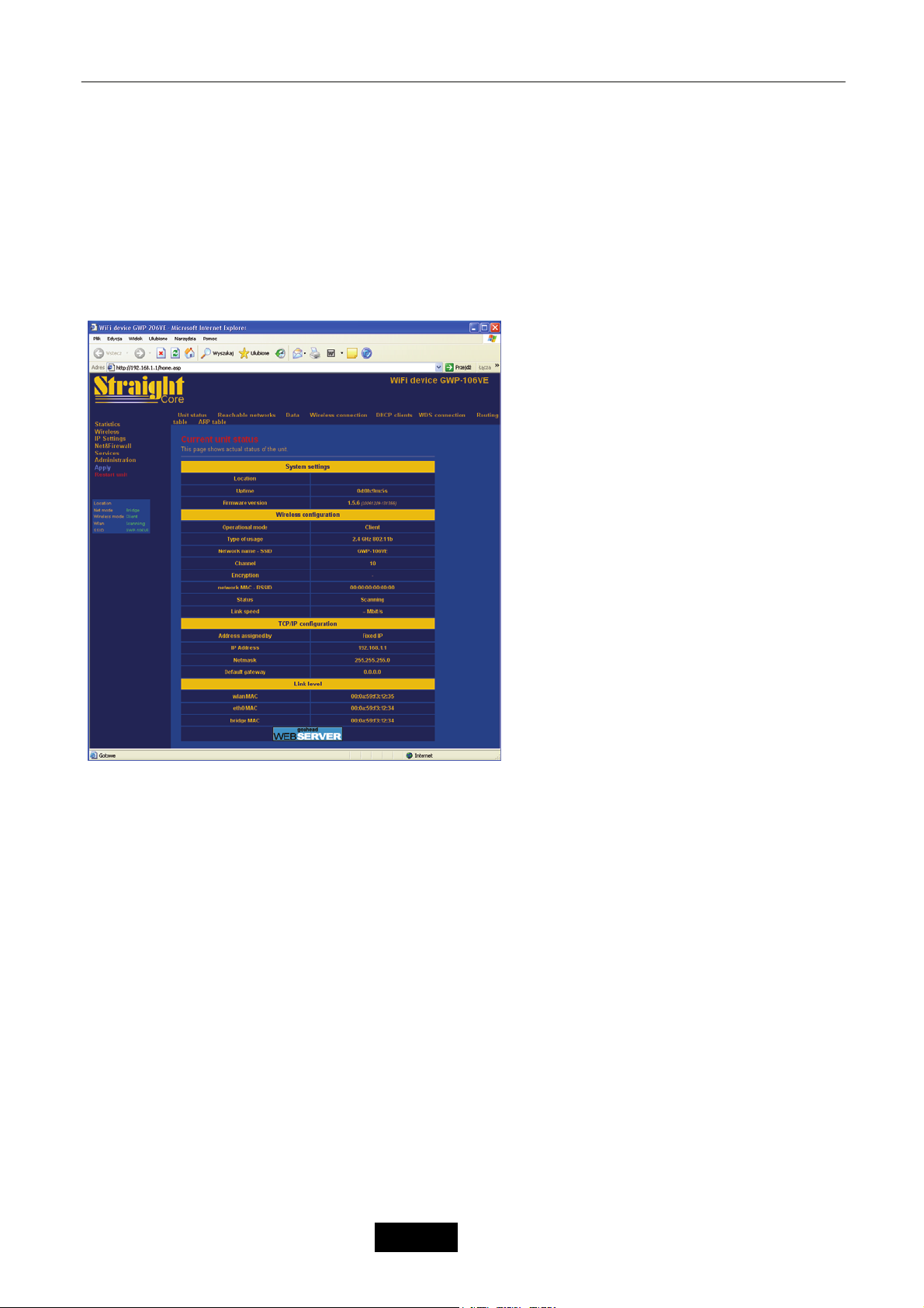
1. Statistic
Odstraňování potíží
Obrazová příloha / Pictures
a) Client
– 31 –
Język Polski
Page 93
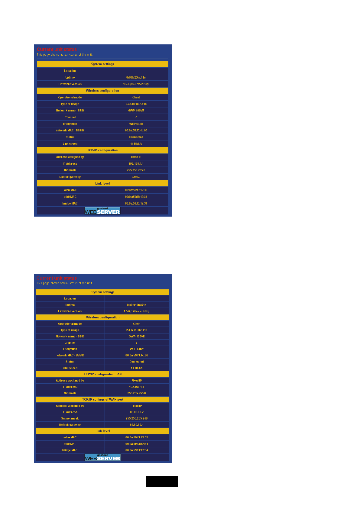
Odstraňování potíží
c)
– 32 –
Język Polski
Page 94
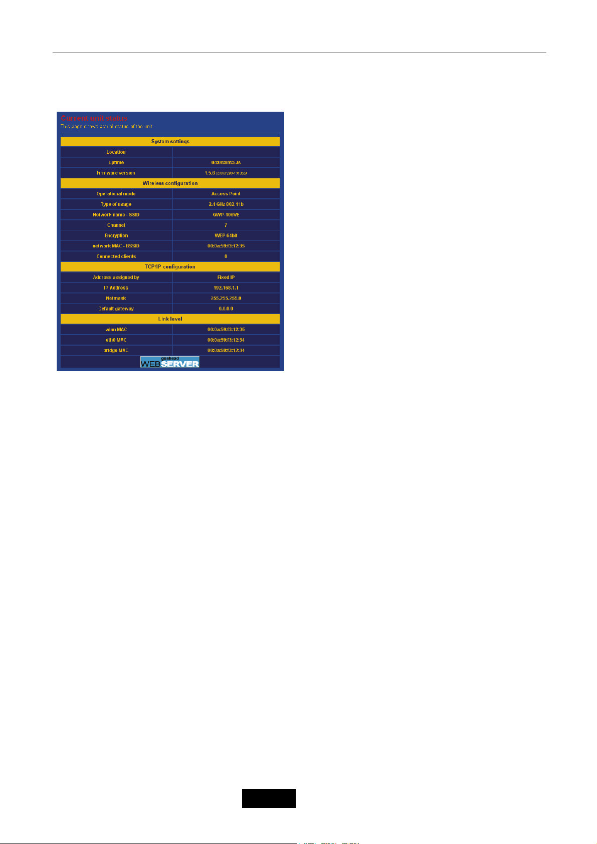
d) Access Point
Odstraňování potíží
e)
– 33 –
Język Polski
Page 95
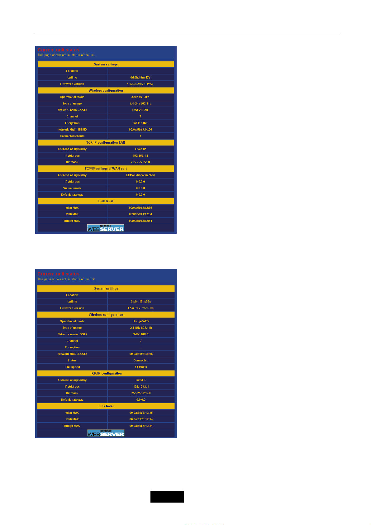
Odstraňování potíží
f) Tryb WDS
– 34 –
Język Polski
Page 96
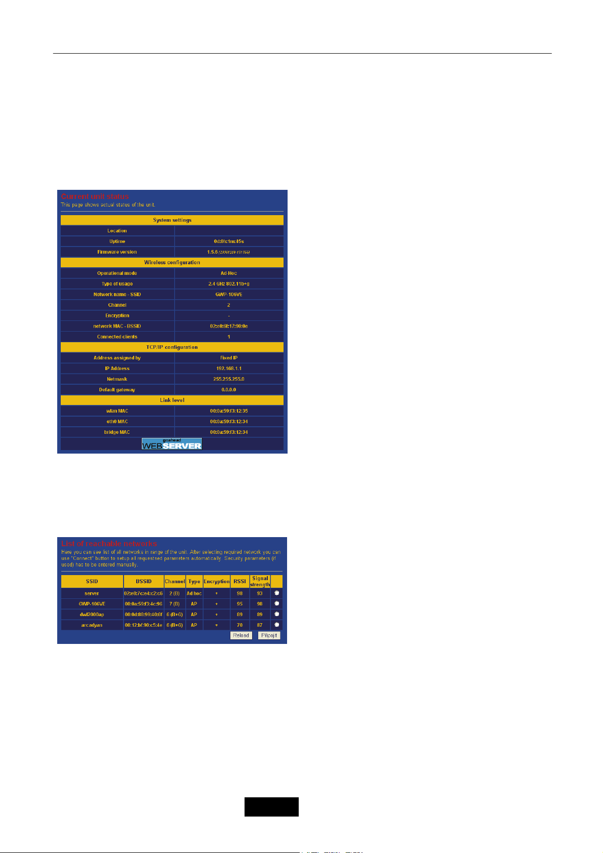
g) Tryb Ad Hoc
Odstraňování potíží
15.1.1 2. Reachable Networks
a) client
b)
– 35 –
Język Polski
Page 97
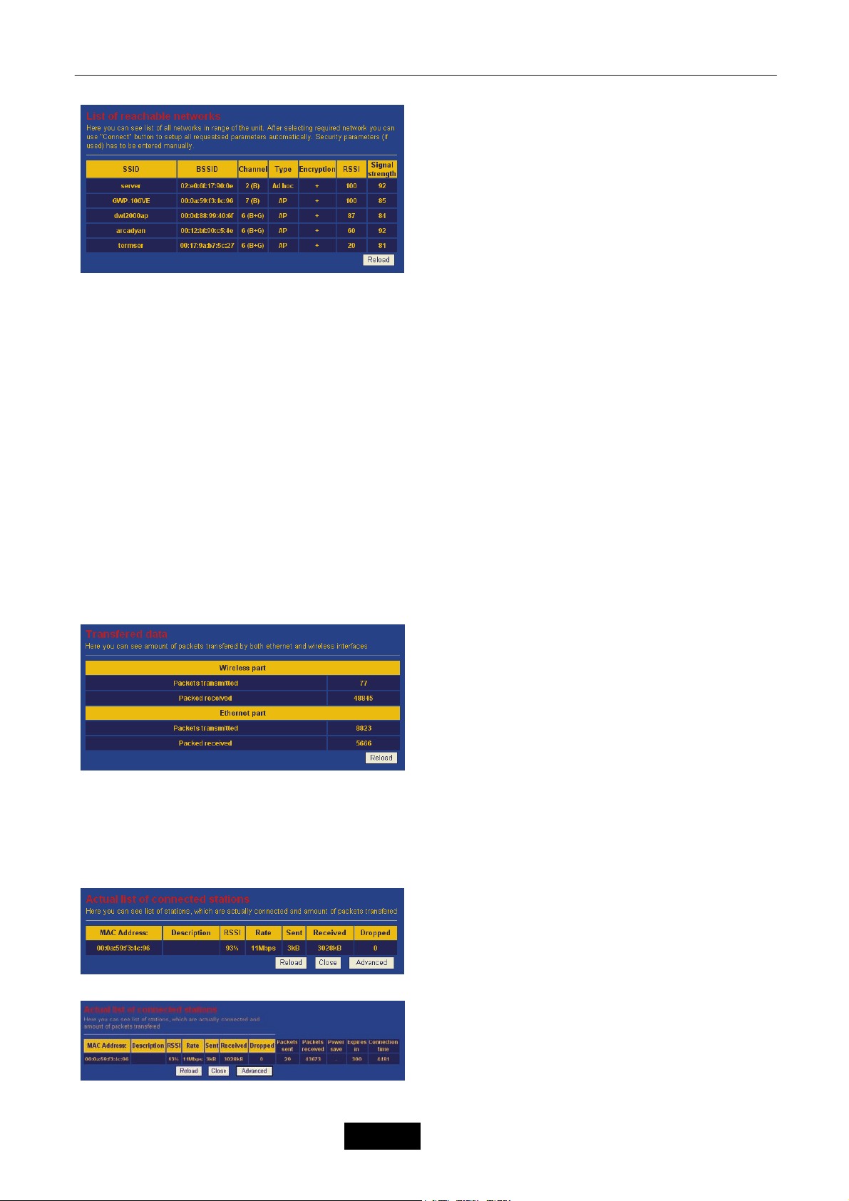
Odstraňování potíží
3. Data
15.1.2 4. Wireless Connection
a)
b)
– 36 –
Język Polski
Page 98
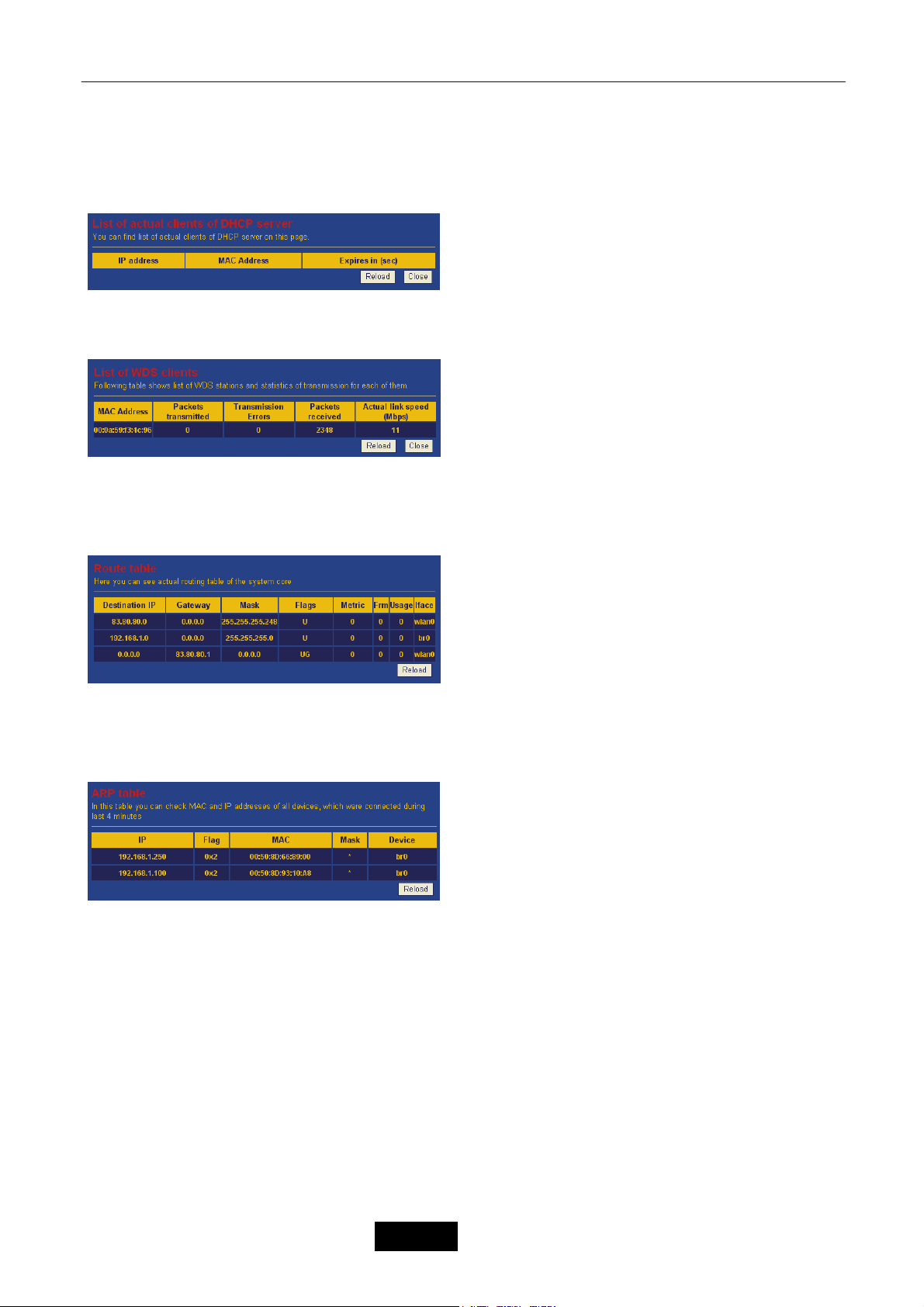
15.1.3 5. DHCP Clients
15.1.4 6. WDS Connection
15.1.5 7. Routing Table
Odstraňování potíží
15.1.6 8. ARP Table
9. Wireless
– 37 –
Język Polski
Page 99
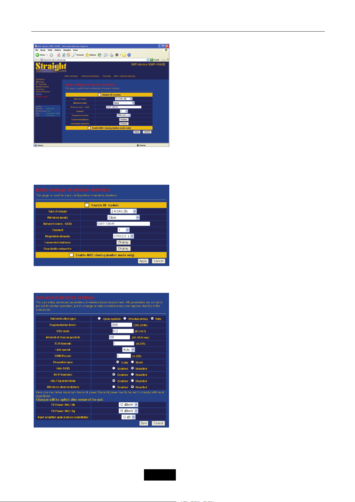
15.1.7 10. Basic Settings
Odstraňování potíží
15.1.8 11. Advanced Settings
– 38 –
Język Polski
Page 100
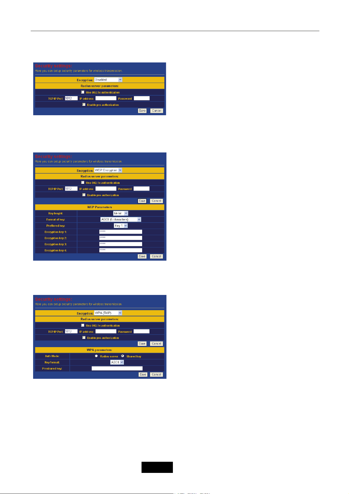
15.1.9 12. Security
15.1.10 13. WEP Encryption
Odstraňování potíží
15.1.10.1 14. WPA/WPA2
– 39 –
Język Polski
 Loading...