

Page 1

)
OPERATION AND PARTS MANUAL
Gasoline Crack Saw
Model RCC130H
Revision #1 (11/18/04
STOW CONSTRUCTION EQUIPMENT
A DIVISION OF MULTIQUIP INC.
POST OFFICE BOX 6254
CARSON, CA 90749
310-537-3700 • 888-252-STOW [888-2527869]
FAX: 310-537-1986 • FAX: 800-556-1986
E-MAIL: stow@multiquip.com • WWW:
stowmfg.com
PARTS DEPARTMENT:
800-427-1244
FAX: 800-672-7877
SERVICE
DEPARTMENT/TECHNICAL
ASSISTANCE:
800-478-1244
FAX: 310-631-5032
Page 2

Page 3

TABLE OF CONTENTS
STOW CRACK SAW MODEL RCC130H
Table Of Contents................................................................................................................................. 3-4
Parts Ordering Procedures ................................................................................................................... 6
Notice to Operators............................................................................................................................... 7-8
Operator Instructional Data Sheet ........................................................................................................ 9
Safety Precautions................................................................................................................................ 10
Preparation ........................................................................................................................................11
Operation ........................................................................................................................................... 12
Maintenance, Repair and Storage..................................................................................................... 13
Assembly .............................................................................................................................................. 14
Removing the Crack Saw from the Pallet.......................................................................................... 14
Before Starting the Engine.................................................................................................................... 14
Filling the Engine Crankcase with Oil ................................................................................................ 14
Filling the RCC130H Series Engine Fuel Tank .................................................................................15
Operation .............................................................................................................................................. 15
Theory of Operation........................................................................................................................... 15
Information Relative to the use of Diamond Blades™....................................................................... 15-17
Installing a Diamond Blade™ on the Arbor Shaft.............................................................................. 17
Transporting the Crack Saw .............................................................................................................. 19-20
Starting the RCC130H Series Gasoline Powered Crack Saw On the Job Site................................. 20
Operating the Crack Saw on the Job Site .........................................................................................21-29
Stopping the RCC130H Gasoline Powered Crack Saw .................................................................... 29
Operational Parameters and Techniques for RCC130H Series Crack Saw ..................................... 29-30
Service/Maintenance ............................................................................................................................31
Preventative Maintenance Check List ............................................................................................... 31
Checking V-Belt Tension and Alignment ........................................................................................... 31
Installing a Replacement V-Belt or Pulley ......................................................................................... 32-34
Installing Replacement Bearings on the Arbor Shaft......................................................................... 34-37
Lubrication Requirements.................................................................................................................. 37
Engine Service................................................................................................................................... 38
Troubleshooting .................................................................................................................................... 39-41
Storage ................................................................................................................................................. 42
Specifications.................................................................................................................
Explanation of Code In Remarks Column ............................................................................................ 44
Suggested Spare Parts......................................................................................................................... 45
....................... 43
RCC130H-CRACK SAW OPERATION AND PARTS MANUAL REV #1 (11/18/04) PAGE 3
Page 4

Component Parts Drawings
Operator Handle Assembly................................................................................................................ 46-47
Drivetrain Assembly........................................................................................................................... 48-49
Frame Assembly................................................................................................................................ 50-51
Dustpan/Vacuum Port Assembly....................................................................................................... 52-53
Wet Cutting Kit Assembly .................................................................................................................. 54-55
Decals ................................................................................................................................................ 56-57
Terms and Condition of Sale —Parts ................................................................................................ 58
TABLE OF CONTENTS
RCC130H-CRACK SAW OPERATION AND PARTS MANUAL REV #1 (11/18/04) PAGE 4
Page 5

NOTE PAGE
RCC130H-CRACK SAW OPERATION AND PARTS MANUAL REV #1 (11/18/04) PAGE 5
Page 6

x
PARTS ORDERING PROCEDURES
Dealer account number
Dealer name and address
Shipping address (if different than billing address)
Return fax number
Application Model number
Quantity, part number and description of each part
Specify preferred method of shipment:
please supply the following information:
FedEx or UPS Ground
FedEx or UPS Second Day or Third Day
FedEx or UPS Next Day
Federal Express Priority One
DHL
Truck
When ordering parts,
Note: Unless otherwise indicated by customer, all
orders are treated as “Standard Orders”, and will
ship within 24 hours. We will make every effort to
ship “Air Shipments” the same day that the order is
received, if prior to 2PM west coast time. “Stock
Orders” must be so noted on fax or web forms.
Here’s how to get help...
Please have the model and serial number on
hand when calling.
Parts Department
800-427-1244 Fax: 800-672-7877
310-537-3700 Fax: 310-637-3284
Service Department
800-478-1244 Fax: 310-537-4259
310-537-3700
Warranty Department
800-421-1244, Ext. 279 Fax: 310-537-1173
310-537-3700, Ext. 279
Sales Department
310-661-4242 Fax: 310-604-9237
877-289-7869 (877-BUY STOW)
Place Your Parts Order Via Web or Fa
For Even More Savings!
Extra Discounts!
All parts orders which include complete part numbers
and are received by our automated web parts order
system, or by fax qualify for the following extra discounts:
Ordered Standard Stock orders
via orders ($750 list and above)
Fax 3% 10%
Web 5% 10%
Special freight allowances
when you order 10 or more
line items via Web or Fax!**
FedEx Ground Service at no charge for freight
No other allowances on freight shipped by any other
carrier.
NOTE: DISCOUNTS ARE SUBJECT TO CHANGE
RCC130H-CRACK SAW OPERATION AND PARTS MANUAL REV #1 (11/18/04) PAGE 6
STOW CONSTRUCTION EQUIPMENT
A DIVISION OF MULTIQUIP INC.
POST OFFICE BOX 6254
CARSON, CA 90749
310-537-3700 • 888-252-STOW [888-252-7869]
FAX: 310-537-1986 • FAX: 800-556-1986
E-MAIL: stow@multiquip.com • WWW: stowmfg.com
Direct TOLL-FREE access
to our Parts Department:
Toll-free nationwide — 800-427-1244
Page 7
IF YOU CAN NOT READ OR DO NOT FULLY UNDERSTAND THE CONTENTS OF THIS
MANUAL, PLEASE CONTACT THE FACTORY FOR PROPER ASSISTANCE BEFORE
ATTEMPTING TO OPERATE THIS PRODUCT.
SI TU NO PUEDES LE'ER O NO COMPRENDES EL CONTENIDO DE ESTE MANUAL
FAVOR DE PONERSE EN CONTACTO CON LA. FABRICA PARA ASSISTENCIA- A
PROPIA ANTES DE INTENTAR PARA OPERAR ESTE PRODUCTO.
SOLLTEN SIE DIESE GEBRAUCHSANWEISUNG NICHT LESEN KOENNEN ODER ES
NICHT VOLLKOMMEN VERSTEHEN, WENDEN SIE SICH BITTE AN DEN HERSTELLER
FUER RICHTIGE HILFE EHE SIE VERSUCHEN DIESES PRODUKT ZU OPERIEREN.
SI VOUS NE LISEZ OU NE COMPRENDRE ENTIEREMENT LES MATIERES DE CE
MANUEL, S'IL VOUS PLAIT, CONTACTEZ L'USINE POUR L'ASSISTANCE APPROPRIEE
AVANT D'UTILISER LE PRODUIT.
NOTICE TO OPERATORS
DANGER
CAUTION
These safety alert symbols identify important safety messages in this manual. When you see these symbols, be
alert to the possibility of personal injury and carefully read the message that follows.
Do not allow anyone to operate the CRACK SAW without first reading this Operator Manual and becoming
familiar with its operation. The manufacturer of the CRACK SAW has gone to great extremes to provide the
owner(s) and/or operator(s) with the finest equipment available for its intended job function of removing covering
materials from concrete and wood floor surfaces. Yet, the possibility exists that the CRACK SAW can be utilized
in and/or subjected to job applications not perceived and/or anticipated by the manufacturer. Such misuse and/or
misapplication of the CRACK SAW can lead to the possibility of serious damage, injury or even death. It is the
responsibility of the owner(s) and/or operator(s) to determine that the CRACK SAW is being utilized and/or
operated within the scope of its intended job function. It is the responsibility of the owner(s) and/or operator(s) to
establish, monitor and constantly upgrade all safety programs and/or practices utilized in and for the operation of
the CRACK SAW. The purpose of such programs is to provide for owner(s') and/or operator(s') safety. Operators
must be instructed to recognize and avoid unsafe conditions associated with their work (29 CFR 1926.21 (b)(2))
and/or applicable updated revisions. It is the responsibility of the owner(s) and/or operator(s) to determine that no
modifications and/or alterations have been made to the CRACK SAW. Modifications and/or alterations can lead to
the possibility of serious damage, injury or even death. It is the responsibility of the owner(s) and/or operator(s) to
make this Operator Manual available for consultation during all phases of operation. Refer to OSHA 2207 and/or
applicable updated revisions which contains all OSHA job safety and health rules and regulations (1926 and
1910) covering construction.
RCC130H-CRACK SAW OPERATION AND PARTS MANUAL REV #1 (11/18/04) PAGE 7
Page 8

CAUTION
The concept of frame mounted type Crack Saws has been successfully utilized for many years as a
practical solution to many types of random crack sawing requirements. The basic concept is proven and
well accepted within the associated marketplaces. Use of a Crack Saw requires strenuous work activity.
This type of work activity can be considered to be greater in magnitude than that experienced with the
use of many other types of both light construction and lawn and garden related equipment. This type of
work activity should only be attempted by operators of adequate physical size and stature, mental
awareness and physical strength and condition. The body parts most noticeably affected during the
planing process are the arms, hands, wrists, shoulders, lower back and legs. The process can also
produce excessive stress/strain directly to the back muscles, spinal vertebrae and many other body
parts. Back related pain can be a side effect of utilizing a Crack Saw. An operator with a chronic back
related problem or a history of back and/or other medically related problems should not attempt to utilize
the Crack Saw. Use of the Crack Saw may only aggravate this and any other medically related problem.
Because of the diverse type of prevailing job applications, job site conditions, operator experience levels
and operator physical characteristics, no warranty, guarantee, representation and/or liability is made by
the manufacturer as to the absolute correctness or sufficiency of any operational procedure, operational
position and/or technique. There is no absolute guarantee that an operator of any given experience level,
physical size and/or physical condition will be immune to the possibility of and/or probable physical side
effects of the normal use of the Crack Saw. Each potential operator must be made aware of and assume
the operational and physical liability described and/or associated with the use of the Crack Saw. Improper
use of the Crack Saw can result in property damage and/or personal injury, including death. Each
potential operator not willing to assume the operational and physical liability described and/or associated
with the use of the Crack Saw, should not operate it. Proper levels of operator experience, skill and
common sense are essential for maximizing the safe and efficient operation of the Crack Saw.
Record the CRACK SAW and electric motor serial numbers in the spaces provided below.
_______________ Model Number
_______________ Serial Number
_______________ Date of Purchase
Specifications and design are subject to change without notice or obligation. All specifications are general in
nature and are not intended for specific application purposes. STOW A Division of Multiquip reserves the right to
make changes in design, engineering or specifications and to add improvements or discontinue manufacture at
any time without notice or obligation. STOW and its agents accept no responsibility for variations which maybe
evident in actual products, specifications, pictures and descriptions contained in this publication.
NOTICE TO OPERATORS
RCC130H-CRACK SAW OPERATION AND PARTS MANUAL REV #1 (11/18/04) PAGE 8
Page 9

The following undersigned operators of the RCC130H CRACK SAW described and/or pertaining to this Operator
Manual have received formal safety and operational information/instruction from the undersigned
owner(s)/instructor(s) in accordance to OSHA 29 CFR 1926.21 (b)(2) and/or applicable updated revisions
pertaining to, but not necessarily limited to the:
1) READING, COMPREHENSION AND ACKNOWLEDGEMENT OF THE MATERIAL COMPRISING THE
ENTIRE CONTENTS OF THE APPLICABLE OPERATOR MANUAL AND APPLICABLE SAFETY AND
OPERATIONAL INFORMATION VIDEO TAPE FOR THE CRACK SAW.
2) FORMALIZED OPERATOR SAFETY PROGRAM TO BE DEVISED BY THE OWNER OF THE CRACK SAW
IN CONJUNCTION WITH THE CONTENTS OF THE APPLICABLE OPERATOR MANUAL AND THE
APPLICABLE SAFETY AND OPERATIONAL INFORMATION VIDEO TAPE FOR THE CRACK SAW.
4) LOCAL LAWS, REGULATIONS AND CUSTOMS RESEARCHED FOR AND/OR BY THE OWNER OF THE
CRACK SAW AND DEEMED APPLICABLE TO THE SAFE AND PROPER USE AND/OR OPERATION OF
THE CRACK SAW FOR ANY SPECIFIC JOB APPLICATION.
5) FORMALIZED MAINTENANCE PROGRAM FOR THE CRACK SAW TO BE DEVISED BY THE OWNER OF
THE CRACK SAW IN ACCORDANCE WITH, BUT NOT NECESSARILY LIMITED TO, THE SPECIFICATIONS,
GUIDELINES AND OPERATIONAL INFORMATION CONTAINED IN THE APPLICABLE OPERATOR
MANUAL.
6) COMPREHENSIVE OPERATIONAL INSTRUCTIONS FOR THE CORRECT AND PROPER USE OF THE
CRACK SAW AS PER THE CONTENTS OF THE APPLICABLE OPERATOR'S MANUAL, SAFETY AND
OPERATIONAL INFORMATION VIDEO TAPE AND APPLICABLE MATERIAL INCLUDED IN THE NATIONAL
ELECTRIC CODE®.
_______________ Operator _______________ Owner/Instructor __________ Date
_______________ Operator _______________ Owner/Instructor __________ Date
_______________ Operator _______________ Owner/Instructor __________ Date
_______________ Operator _______________ Owner/Instructor __________ Date
_______________ Operator _______________ Owner/Instructor __________ Date
_______________ Operator _______________ Owner/Instructor __________ Date
NOTE: INSERT COPIES OF THIS PAGE WITHIN THE OPERATOR'S MANUAL IF SPACE FOR ADDITIONAL
OPERATORS IS REQUIRED.
OPERATOR INSTRUCTIONAL DATA SHEET
RCC130H-CRACK SAW OPERATION AND PARTS MANUAL REV #1 (11/18/04) PAGE 9
Page 10
SAFETY PRECAUTIONS
THE FOLLOWING SAFETY PRECAUTIONS
PROVIDE SOME COMMON SENSE GUIDES TO
PROMOTE SAFETY AND EFFICIENCY WITH THE
CRACK SAW. NO WARRANTY, GUARANTEE OR
REPRESENTATION IS MADE BY THE
MANUFACTURER AS TO THE ABSOLUTE
CORRECTNESS OR SUFFICIENCY OF ANY
INFORMATION OR STATEMENT. THESE SAFETY
PRECAUTIONS ARE INTENDED TO DEAL
PRINCIPALLY WITH COMMON PRACTICES AND
CONDITIONS ENCOUNTERED IN THE USE OF
THE CRACK SAW AND ARE NOT INTENDED TO
BE ALL INCLUSIVE. PROPER LEVELS OF
OPERATOR EXPERIENCE, SKILL AND COMMON
SENSE ARE ESSENTIAL FOR SAFE AND
EFFICIENT OPERATION.
THE ENGINE EXHAUST FROM THIS PRODUCT
CONTAINS CHEMICALS KNOWN TO THE STATE
OF CALIFORNIA TO CAUSE CANCER, BIRTH
DEFECTS OR OTHER REPRODUCTIVE HARM.
THIS STATEMENT IS MADE IN COMPLIANCE TO
CALIFORNIA PROPOSITION 65..
DANGER
DANGER
DANGER
INCORRECT USE OF THE CRACK SAW CAN
RESULT IN PROPERTY DAMAGE, PERSONAL
INJURY OR EVEN DEATH. TO REDUCE THIS
POSSIBILITY, GIVE COMPLETE AND UNDIVIDED
ATTENTION TO THE JOB AT HAND AND
FOLLOW THESE SAFETY PRECAUTIONS:
PREPARATION.
1) This Crack Saw is specialized type of powered
equipment, designed for a specific job function and
requires adequate and thorough instruction
BEFORE it is operated. The size, power, complexity
and operating characteristics of this type of powered
equipment would dictate that each operator must
receive adequate, professional instruction regarding
the proper operation of this Crack Saw before being
allowed to utilize it. BEFORE attempting to utilize
this Crack Saw, read this Operator's Manual, the
applicable Safety and Operational Information Video
Tape and the material supplied by the engine
manufacturer to familiarize each operator with its
correct operating procedures. Avoid the urge not to
take the necessary time to read this Operator's
Manual before operating the Crack Saw. DO NOT
OPERATE THE CRACK SAW UNTIL EACH
OPERATOR COMPLETELY COMPREHENDS THE
CONTENTS OF THIS MANUAL AND THE
APPLICABLE SAFETY AND OPERATIONAL
INFORMATION VIDEO TAPE.
2) Develop a comprehensive program for the safe
operation of the Crack Saw by its owner(s) and/or
operator(s). Such a program will include, but is not
limited to: instructional requirements for operation,
applicable OSHA requirements, local laws and
regulations, job site safety and a Crack Saw
maintenance program. Constantly examine and
upgrade this program to guarantee owner(s) and/or
operator(s) safety. Each operator must be fully
instructed regarding the specifics of this safety
program.
3) Determine that the Crack Saw is in its original,
factory configuration and has not been modified in
any manner. Many modifications can result in
potentially dangerous configurations that can lead to
property damage and/or personal injury. If there are
any questions about possible modifications made to
the Crack Saw, contact the Customer Service
Department for specific information BEFORE
utilization. There is no charge for this service. Do not
operate the Crack Saw without the use of the
original equipment V-belt and diamond blade
guards. Use of the Crack Saw without an approved
belt guard and/or diamond blade guard can lead to
property damage and/or personal injury.
4) Minors should never be allowed to operate the
Crack Saw. Bystanders, especially children and
animals, should not be allowed in the area where the
Crack Saw is in use. The sawing process can result
in flying particles being emitted at high velocity and
striking the operator and/or onlookers. This can lead
to the possibility of property damage and/or personal
injury. Keep all body parts, loose clothing, foreign
objects and onlookers clear of the rotating diamond
blade, caster wheels, main wheels and flying
particles.
5) Operators must be in adequate physical
condition, mental health and not under the influence
of any substance (drugs, alcohol, etc.) which might
impair vision, dexterity or judgment. Working with
the Crack Saw is strenuous. If you have any
condition that might be aggravated by strenuous
work, check with your doctor BEFORE operating the
Crack Saw. Guard against the possibility of back
related injuries. Always lift the Crack Saw with leg
muscles and not with the back.
RCC130H-CRACK SAW OPERATION AND PARTS MANUAL REV #1 (11/18/04) PAGE 10
Page 11

SAFETY PRECAUTIONS
6) Prolonged use of the CRACK SAW (or other,
similar machines) exposes the operator to vibrations
which may produce Whitefinger Disease (Raynaud's
Phenomenon). This phenomenon reduces the
hand's ability to feel and regulate temperature,
produces numbness and burning sensations and
may cause nerve and circulation damage and tissue
necrosis. Antivibration systems do not guarantee
that you will not sustain Whitefinger Disease.
Therefore, continuous and regular users should
closely monitor the condition of their hands and
fingers. After each period of use, exercise to restore
normal blood circulation. If any of the symptoms
appear, seek medical advice immediately.
7) Clothing must be sturdy and snug fitting, but allow
complete freedom of movement. Never wear loose
fitting jackets, scarves, neckties, jewelry, flared or
cuffed pants or anything that could become caught
on controls or moving parts. Wear long pants to
protect your legs. Protect your hands with heavy
duty, nonslip gloves to improve your grip. Good
footing is most important when operating the
CRACK SAW. Wear sturdy boots with nonslip soles.
Steel-toed safety shoes are highly recommended.
Keep shoes properly laced. Never wear tennis
shoes or other, similar type shoes which afford little
or no protection. Wear an approved safety hard hat
to protect the operator'(s') head(s) where there is a
danger of head injuries. Noise, generated by the
operation of the CRACK SAW and the actual
process itself, can damage your hearing. Wear
approved sound barriers (ear plugs or ear mufflers)
to protect your hearing. Continuous and regular
operators should have their hearing checked
regularly.
8) Visually inspect the Crack Saw, components,
tools and accessories for damaged or worn parts.
BEFORE each use:
a) Disconnect the engine spark plug wire or power
source cable.
b) Clean and remove all accumulated foreign matter
from the wheels and determine that each rotates
freely.
c) Clean and remove all accumulated foreign matter
from inside the main frame area.
d) Inspect the V-belt drive for proper tension, wear
and general condition. Replace each component as
necessary.
e) Inspect the arbor shaft and diamond blade guard
assemblies for excessive wear and structural
integrity. Replace each component as necessary.
The arbor shaft rotates at high speed during the
specific process and can be subject to high wear
rates if the installed diamond blade is not properly
maintained and/or replaced at regular service
intervals.
f) Determine that operator controls work freely, all
safety devices are operative and information decals
are readable.
g) Check to see that the Crack Saw and all related
accessories are in good, mechanical condition
BEFORE utilization.
h) Reconnect the spark plug wire or power source
cable as applicable
9) Contact appropriate representatives to determine
if/where electrical cables, gas lines and other
hazardous items are buried under the work surface
BEFORE utilization. The Crack Saw and related
accessories are not insulated. Contact with buried
electrical cables, gas lines and other hazardous
items can result in electrocution and/or an explosion.
10) Know how the controls operate. Know how to
stop the engine or electrical motor quickly in an
emergency. Always start the engine or electric motor
according to the instructions as outlined in this
manual to minimize the possibility of unexpected
contact with the work surface. Unexpected contact
with the work surface can cause loss of machine
control, and the possibility of property damage
and/or personal injury.
11) Never exceed the recommended capacities of
the Crack Saw. Refer to the Specifications section
of this manual for more detailed information.
RCC130H-CRACK SAW OPERATION AND PARTS MANUAL REV #1 (11/18/04) PAGE 11
Page 12

SAFETY PRECAUTIONS
OPERATION.
1) Give complete and undivided attention to the job
at hand. Do not chew gum, smoke and/or use
smokeless tobacco while utilizing the Crack Saw. Do
not attempt to eat and/or drink while utilizing the
Crack Saw. Determine that eyeglasses and/or
hearing aid devices are properly secured
Use of the Crack Saw is strenuous and causes
fatigue. Help prevent the cause of an accident. Plan
to take work breaks as required to help maintain
proper mental and physical alertness.
2) This CRACK SAW is not sealed or insulated. Do
not operate the CRACK SAW in an explosive
atmosphere or near combustible materials. Refer to
current OSHA® rules and regulations.
3) Gasoline is an extremely flammable fuel. Use
extreme caution when handling gasoline or mixing
fuel. Always utilize UL®, CSA® OR CE approved
containers for the storage and transportation of fuel.
Do not smoke or bring fire or flame near the fuel.
Always shut off the engine and allow it to cool before
refueling. Never remove the fuel tank filler cap while
the engine is running. Never operate an engine
without a fuel tank filler cap. Select bare ground for
fueling and move at least 10 feet from the fueling
spot before starting the engine. Wipe off any spilled
fuel before starting the engine and check for
leakage. If a fuel or oil leak is found, do not start or
run the engine until the leak is fixed and the spillage
has been wiped away. Take care not to get fuel or
oil on your clothing. If this happens, change your
clothing immediately. Before operating the Crack
Saw refer to the Specifications section of this
manual for more detailed information regarding fuel
and lubrication requirements.
4) The Crack Saw is designed for use by one
operator. Use of the Crack Saw by more than one
operator can lead to confusion and loss of control,
resulting in property damage and/or personal injury.
If it is felt that more than one person is required to
operate the Crack Saw, STOP and contact the
Customer Service Department for specific
operational and service/maintenance information.
There is no charge for this service.
5) Do not operate the Crack Saw with onlookers
close by. Caution all onlookers to stand clear. The
sawing process can result in flying particles being
emitted at high velocity and striking the operator
and/or onlookers. This can lead to the possibility of
property damage and/or personal injury. Keep all
body parts, loose clothing and foreign objects clear
of the rotating diamond blade.
6) Start the engine or electric motor according to the
instructions as outlined in this manual to minimize
the possibility of unexpected contact with the work
surface. Unexpected contact with the work surface
can cause the loss of machine control and the
possibility of property damage and/or personal
injury.
7) Start and operate the Crack Saw only in a well
ventilated area. Carbon Monoxide fumes given off
by an engine are poisonous. Breathing these fumes
can result in property damage and/or personal
injury. Operate the Crack Saw only when/where
visibility and light are adequate for the job at hand.
Work carefully. Always hold the operator handle
firmly with both hands. Wrap your fingers around the
handle, keeping it cradled between your thumbs and
fingers. Always make sure the operator handle is in
good condition and free of moisture, pitch, oil or
grease. Wear gloves to improve your grip. Never
leave the Crack Saw running unattended.
8) Special care must be exercised on slippery
conditions and on difficult, uneven surfaces. Watch
for cracks, high spots and other, surface
irregularities. Keep proper footing and balance at all
times. The normal use of this machine is on level
surfaces. Other terrains can be dangerous and
should be avoided. Only properly trained operators
should attempt these techniques.
9) Never start the engine or electric motor with the
Crack Saw directly over cracked, uneven or irregular
surfaces. Start the engine or electric motor
according to the instructions as outlined in this
manual.
10) Contact with a hot, engine muffler can cause
property damage and/or personal injury. Remain
clear of a hot, engine muffler. Do not over speed the
engine by altering the governor setting or by
disconnecting the engine governor. Serious damage
to the engine and/or personal injury can result.
11) Clean and remove all accumulated foreign
matter from inside the main frame area after each
use. This practice will maximize bearing and V-belt
service life.
12) Because this Crack Saw is classified as a low
cost, hand held, low horsepower, portable type
machine, it is limited in the number of practical
and/or suitable job applications. A particular job site,
actual surface conditions, job specifications and
operator skill/common sense may dictate that a
different type of machine (with characteristics of
higher purchase cost, being mounted to a carrier
RCC130H-CRACK SAW OPERATION AND PARTS MANUAL REV #1 (11/18/04) PAGE 12
Page 13

SAFETY PRECAUTIONS
vehicle, with greater horsepower and less mobility),
method and/or process be utilized to properly
complete the job with the degree of efficiency and
safety required. Contact the Customer Service
Department for specific information regarding
suitable job applications, job sites surface conditions
and operator experience/skill/common sense
recommendations for this Crack Saw BEFORE
utilization. There is no charge for this service.
MAINTENANCE, REPAIR AND STORAGE.
1) Use only genuine, approved replacement parts
and accessories for maintenance and repair. Use of
parts and accessories manufactured by others can
result in property damage and/or personal injury.
2) Follow the Service instructions as outlined in the
appropriate section of this manual.
3) Always stop the engine or electric motor and
disconnect the spark plug wire or power source
cable BEFORE checking or working on the Crack
Saw.
4) Always properly maintain the Crack Saw.
Frequently check all fasteners and individual parts.
Built in safety features are effective only if they are
maintained in good working condition. Replace any
questionable part or assembly with a genuine,
factory approved, replacement part. Do not forsake
proper maintenance for the price of a few
replacement parts. Proper maintenance does not
cost...it actually pays dividends. Do not attempt any
maintenance repair work not described in this
manual. Have such work performed at your dealer's
service facility.
5) A worn or damaged engine muffler is a fire hazard
and may cause loss of hearing. Check to see that
the muffler is in good condition. If the muffler is
equipped with a spark arresting device, determine
that it is in proper working condition at regular
service intervals. Replace the spark arresting device
with an approved replacement if there is any
question of it integrity. It is the responsibility of the
owner(s) and/or operator(s) to provide for and
properly maintain a USDA approved, spark arresting
muffler in an operating area specified by law. Check
with appropriate governing agencies for more
specific information. The Crack Saw must not be
operated if the muffler is faulty or has been
removed. Contact with a hot engine muffler can
cause property damage and/or personal injury.
6) Do not operate the Crack Saw without the use of
factory approved V-belt and diamond blade guards
that are maintained in proper structural condition.
Frequently inspect the guards for signs of wear,
cracks and other signs of fatigue. If there is any
question regarding the structural integrity and/or
condition of the belt guard, properly dispose and
replace with a genuine, factory approved,
replacement part only.
7) Maintain all safety and operation decals in proper
condition. If any decal becomes damaged and/or
unreadable, replace with a genuine, factory
approved, replacement part only.
8) The Crack Saw utilizes many self locking type
hexagon head nuts to minimize the effects of
vibration. Replace all self locking hardware with
genuine, factory approved, replacement parts only.
9) Consult the material supplied by the engine or
electric motor manufacturer for specific information
relative to proper operational, lubrication and
storage requirements.
RCC130H-CRACK SAW OPERATION AND PARTS MANUAL REV #1 (11/18/04) PAGE 13
Page 14
ASSEMBLY INSTRUCTIONS/OPERATIONS
Assembly
The RCC130H Crack Saw is shipped from the
factory secured on a specially designed wooden
pallet and protected from external damage by a
corrugated carton or wood crate. If shipped with a
corrugated carton, the Crack Saw can be secured to
the pallet by wood laths nailed to the pallet body.
Remove the carton or crate immediately upon
receipt using suitable tools to remove the nails.
REMOVING THE CRACK SAW FROM THE
PALLET.
Tools Required:
1 each, pliers.
1 each, claw hammer or a hammer and an
appropriate pry bar.
The Crack Saw is secured to the pallet with steel
banding. Using the pliers, cut and remove the
banding. The Crack Saw can then be removed from
the pallet.
DANGER
WEAR SAFETY GLASSES AND OTHER
APPROPRIATE SAFETY APPAREL WHEN
CUTTING THE STEEL BANDING AND/OR
REMOVING THE CORRUGATED/WOOD
SHIPPING CRATE.
Visually inspect the shipment for freight damage
and/or missing parts. If shipping damage is evident,
contact the delivering carrier immediately to arrange
for an inspection of the damage by their claims
representative. Federal law requires that a claim be
filed within a specific time period. If missing parts are
detected, notify your dealer who will assist you in
obtaining them.
The Crack Saw is shipped from the factory
completely assembled. If ordered with the Crack
Saw, attachments or accessories are normally
shipped separately to minimize the potential for loss
during shipment.
Check all fasteners for proper security. Consult a
fastener torque chart for the proper torque value if
any fastener is found to require retorquing.
Before Starting the Engine
FILLING THE ENGINE CRANKCASE WITH OIL.
Note: The RCC130H Crack Saw is shipped with oil
in the engine crankcase. Fuel is drained from the
fuel tank and will be marked accordingly by factory
personnel.
Tools Required:
1 each, small, clean funnel.
The RCC130H Series Crack Saw comes equipped
with a Honda 13 HP gasoline engine. The engine is
not normally pre-serviced at the factory (see note
above) and will require the addition of oil in the
crankcase before being placed in service. Consult
the material supplied by the engine manufacturer for
the engine that has been ordered with your Crack
Saw. Carefully review this material to become
familiar with specific operating characteristics,
recommendations and service requirements.
1) Determine the location(s) of both the oil filler and
oil drain plug(s).
2) Wipe oil, dust and accumulated dirt from the filler
plug area.
3) Using the funnel, fill the engine crankcase with a
high grade motor oil. Consult the material supplied
by the engine manufacturer for proper amount,
weight and service classification.
4) Replace the oil filler plug and tighten. Wipe off
any excess oil spilled on the engine crankcase and
Crack Saw.
5) Do not operate the engine unless proper oil level
is maintained as per the material supplied by the
engine manufacturer.
FILLING THE RCC130H FUEL TANK.
Tools Required:
1 each, small, clean funnel.
CAUTION
Never mix oil with gasoline. Four cycle engines
are not designed to be operated with oil mixed
with the gasoline.
RCC130H-CRACK SAW OPERATION AND PARTS MANUAL REV #1 (11/18/04) PAGE 14
Page 15

ASSEMBLY INSTRUCTIONS/OPERATIONS
1) Determine the location of the fuel tank filler cap.
2) Carefully clean the filler cap and surrounding area
to insure that no dirt or debris falls into the fuel tank.
Remove the filler cap.
3) Using the funnel, fill the fuel tank with fresh, clean
fuel according to the specifications outlined in the
material supplied by the engine manufacturer. Do
not overfill the tank or spill any fuel. If the fuel tank
incorporates a screen mesh to prevent debris from
falling into the tank, do not remove to increase the fill
rate. Replace the filler cap. Wipe away any excess
spilled fuel.
DANGER
MANY FUELS ARE EXTREMELY FLAMMABLE.
DO NOT SMOKE NEAR THE FUEL TANK. DO
NOT FILL THE FUEL TANK WITH THE ENGINE
RUNNING OR IF IT IS HOT. ALLOW AMPLE TIME
BETWEEN EACH REFUELING FOR THE ENGINE
TO COOL.
Operation
THEORY OF OPERATION.
The RCC130H Crack Saw operates on the principle
of transmitting horsepower through a V-Belt
transmission directly to an industry standard, 8 inch
diameter, diamond segment blade of various widths.
The crack sawing process is directly controlled by
these conditions:
a) The use of a suitable mechanism (diamond blade)
of proper design and configuration to penetrate the
work surface and remove material while delivering
acceptable service life.
b) Sufficient static weight supporting the diamond
blade to allow it to effectively penetrate the work
surface and remove material.
c) Adequate horsepower capable of rotating the
diamond blade at industry recognized speeds
against the work surface to deliver acceptable
productivity rates.
Since no two materials are exactly alike, no two
work surface materials can be sawed by the exact
same method. The nature of the sawing process,
along with operator experience, skill and common
sense, would suggest that efficient and productive
crack sawing is a matter of trial and error.
Combinations of diamond blade type, condition, and
feed rate are direct factors that will also determine
the overall success of the job application.
INFORMATION RELATIVE TO THE USE OF
DIAMOND BLADES.
Safety requirements always override performance
considerations. Diamond blade technology has
made such rapid advances during the past few
years that a diamond blade, properly used, on well
designed and well maintained equipment, can
provide the lowest cost per cut of any of the
methods of cutting now in use. But, put that same
blade onto a piece of poorly maintained equipment
and in the hands of a poorly trained operator and the
cost of cutting can virtually put you out of business.
The members of the Saw Manufacturer's Institute
have been a significant contributor to the state of the
diamond blade art. We hope that some of the
knowledge and experience that we have
accumulated in our many years in the business can,
through this booklet, assist you in keeping your cost
down to an absolute minimum.
Of all the problems that confront diamond blade
users, blade wear is the most difficult to accurately
evaluate. Reporting life performance of identical
diamond blade specifications operating under
seemingly identical conditions tend to be
inconsistent.
Masonry blade operators frequently report blade life
in terms of hours, days or weeks. However, these
reports neglect to mention type of material being cut,
the size of the cuts, and the number of cuts per day.
In addition, the amount and the cleanliness of the
water and the amount of pressure the operator
applies to the cut have an effect on blade life.
Obviously, trying to compare the life of one diamond
blade with another, simply on the basis of hours, is
analogous to trying to compare a set of tires on one
car with an identical set on another car...it is virtually
impossible. There are just too many variables...the
weight of the car, the types of roads driven on, the
condition of the car...particularly the suspension, the
manner in which the operator handles the car, etc.
Just as many variables apply to diamond blades.
So, the next time you have reason to compare blade
life, keep these variables in mind. Some of the
problems arising from these variables can be quickly
identified, and possibly corrected"...
Excerpt from: Rx for Diamond Blades, Problems,
Causes, Effects, Remedies, published by the
Masonry and Concrete Manufacturers Institute.
RCC130H-CRACK SAW OPERATION AND PARTS MANUAL REV #1 (11/18/04) PAGE 15
Page 16

ASSEMBLY INSTRUCTIONS/OPERATIONS
DANGER
IMPROPER USE OF A DIAMOND BLADE WITH
THE CRACK SAW CAN RESULT IN PROPERTY
DAMAGE AND/OR PERSONAL INJURY.
DANGER
PROPER OPERATIONAL USE OF A DIAMOND
BLADE THAT DOES NOT MEET INDUSTRY
SPECIFICATIONS AND/OR SAFETY
STANDARDS WITH THE CRACK SAW CAN
RESULT IN PROPERTY DAMAGE AND/OR
PERSONAL INJURY.
General Information.
1) " Only mature, properly instructed adults should
be permitted to operate machinery and tools.
2) Only utilize the blade to cut the material it is
designed and intended to cut. Blades intended for
masonry material (stone, concrete bricks, blocks) or
blades for steel or ductile iron must only be used in
those materials. If you need to cut a material other
than the ones listed above, you must use a blade
that has been designed for that specific material.
Use of a blade in the wrong material may involve a
considerable safety risk. It may also reduce the life
of the blade or damage the blade.
3) Inspect all diamond blades for damage before
use.
4) Never use a new or used diamond blade that
shows damage such as cracks, missing segments,
damage to the arbor hole or by the flange washers,
or other appearances not consistent with the
appearance of a new blade. These are indications of
previous improper use. If you have any doubt about
the safety of a blade, contact the Customer Service
Department of the blade manufacturer for
assistance. If you do not know the name of the blade
manufacturer, contact the Customer Service
Department of General Equipment Company for
assistance. There is no charge for this service.
5) Always check that the two mounting flanges are
of the same diameter and that they are clean and
flat. The flanges should not have any cracks or show
any abnormal wear. Make sure that the arbor bolt or
nut is the correct one for the equipment without
damage to the threads. Improper or damaged flange
washers and/or damaged fasteners can damage the
blade or cause the blade to come loose from its
mount. A blade that comes loose can cause serious
bodily injury or death to the operator or bystander. If
there are any questions regarding the suitability of a
specific mounting flange, contact the Customer
Service Department for assistance BEFORE utilizing
the diamond blade. There is no charge for this
service.
6) Always make sure that the arbor hole in the blade
matches the one on the equipment. Do not force the
blade onto the spindle. Do not use an arbor shaft
(spindle) and blade combination of different sizes.
Proper fit is achieved when the blade slides onto the
arbor without having more than 0.1 mm (0.005 inch)
radial play.
7) Always tighten the bolt or nut for the flange
washers in accordance with the equipment
manufacturer's specifications.
8) Always make sure that the equipment used is in
good operating condition in accordance with the
manufacturer's specifications. Do not operate the
equipment unless the guards are in good condition,
in the proper place and secure. If the equipment
appears to be missing any fasteners or has any
parts that appear loose or worn, do not operate the
equipment until the appropriate repairs are
performed. Always make sure the blade you intend
to use with the equipment meets all the equipment
manufacturer's specifications.
9) Do not operate the equipment with other than the
recommended blade sizes. This can result in severe
blade damage. Contact the machine manufacturer
for advice.
10) Make sure that the spindle speed on the
machine does not exceed the maximum RPM
indicated on the diamond blade. This can result in
blade breakage. Check the blade shaft with a
tachometer to verify that the equipment's maximum
RPM does not exceed the manufacturer's
specifications.
11) Blades designed for wet cutting must be cooled
by an adequate, continuous water flow to each side
of the blade. Lack of enough coolant will cause
excessive heat, poor blade performance and
possible segment loss.
12) Blades designed for dry cutting may be used
without water coolant. However, dry cutting blades
can overheat which will result in loss of blade
tension and may ruin the blade. The risk is greatest
during long continuous cutting. Most overheating
problems can be avoided by lifting the blade out of
RCC130H-CRACK SAW OPERATION AND PARTS MANUAL REV #1 (11/18/04) PAGE 16
Page 17
ASSEMBLY INSTRUCTIONS/OPERATIONS
the cut and letting it cool by rotating in the air for 15
to 20 seconds after every one minute of cutting.
13) Do not force the tool into the material to be cut.
A properly working diamond tool will grind the
material without excessive force being applied. If
excessive force is needed, it indicates there is
damage to the blade to the blade or the wrong blade
is being used.
14) Always inspect the diamond blade and the
equipment any time you stop during the cut. If you
notice any difference in performance as your work
progresses, immediately STOP and inspect the
equipment and the diamond tool.
15) Do not operate any diamond tool without full
knowledge about appropriate cooling of the tool. If a
tool is not cooled properly, the blade core can
become damaged resulting in the segments coming
loose or the blade core (the steel) breaking. This
can result in serious bodily injury or death to the
operator or bystander.
16) Do not allow any bystanders in the work area.
Never allow anyone to stand in front of a saw that is
about to be started or is running.
Standards.
The manufacturing of machinery and grinding
wheels and the usage of these products are covered
in several OSHA and ANSI standards. The most
applicable standard for these products is ANSI B7.1
and B7.5. Copies of these standards can be
obtained from the American National Standards
Institute, 1430 Broadway, New York, NY 10018.
Personal Safety Equipment.
1) Always wear dust masks (respirators) approved
for use in concrete and stone dust.
2) Always wear approved eye protection such as
goggles or face shield.
3) Always wear approved hearing protection.
4) Always wear approved head protection.
5) Always wear approved safety footwear.
6) Always wear approved gloves.
Note.
In the manufacturing of all diamond blades different
metals are used such as Boron, Copper, Colbalt,
Nickel, Iron, Tungsten, Molybdenum, Tin, etc., as
outlined in the Material Safety Data Sheet (MSDS).
This product as sold presents no hazard although,
during use, small amounts of these metal
substances may be released into the dust or slurry
generated from the material being cut or ground.
Prolonged exposure to excessive amounts of dust
and slurry may cause respiratory disease, skin
irritation or cancer.
Common Sense.
Almost all accidents are avoidable if you apply
caution and common sense. Follow all safety
precautions at all times. If you are not sure...simply
don't do it. Ask for advice. Used improperly or
carelessly any tool is dangerous and may cause
severe bodily injury or death. If tools are used with
caution, proper techniques and common sense, they
will do an excellent job for you"...
Excerpt from: Instructions for the Safe Use of
Diamond Tools, published by Dimas Industries.
INSTALLING A DIAMOND BLADE ON THE
ARBOR SHAFT.
Tools required:
1 each, 3/4 inch wrench.
1 each, PN CS8-0400 1-1/2 inch wrench or
equivalent.
DANGER
WHEN INSTALLING A DIAMOND BLADE ON THE
ARBOR SHAFT ALWAYS WEAR THE
APPROPRIATE SAFETY EYEWEAR AND
APPAREL TO MINIMIZE THE POTENTIAL FROM
FLYING DEBRIS. FLYING DEBRIS CAN RESULT
IN PROPERTY DAMAGE AND/OR PERSONAL
INJURY.
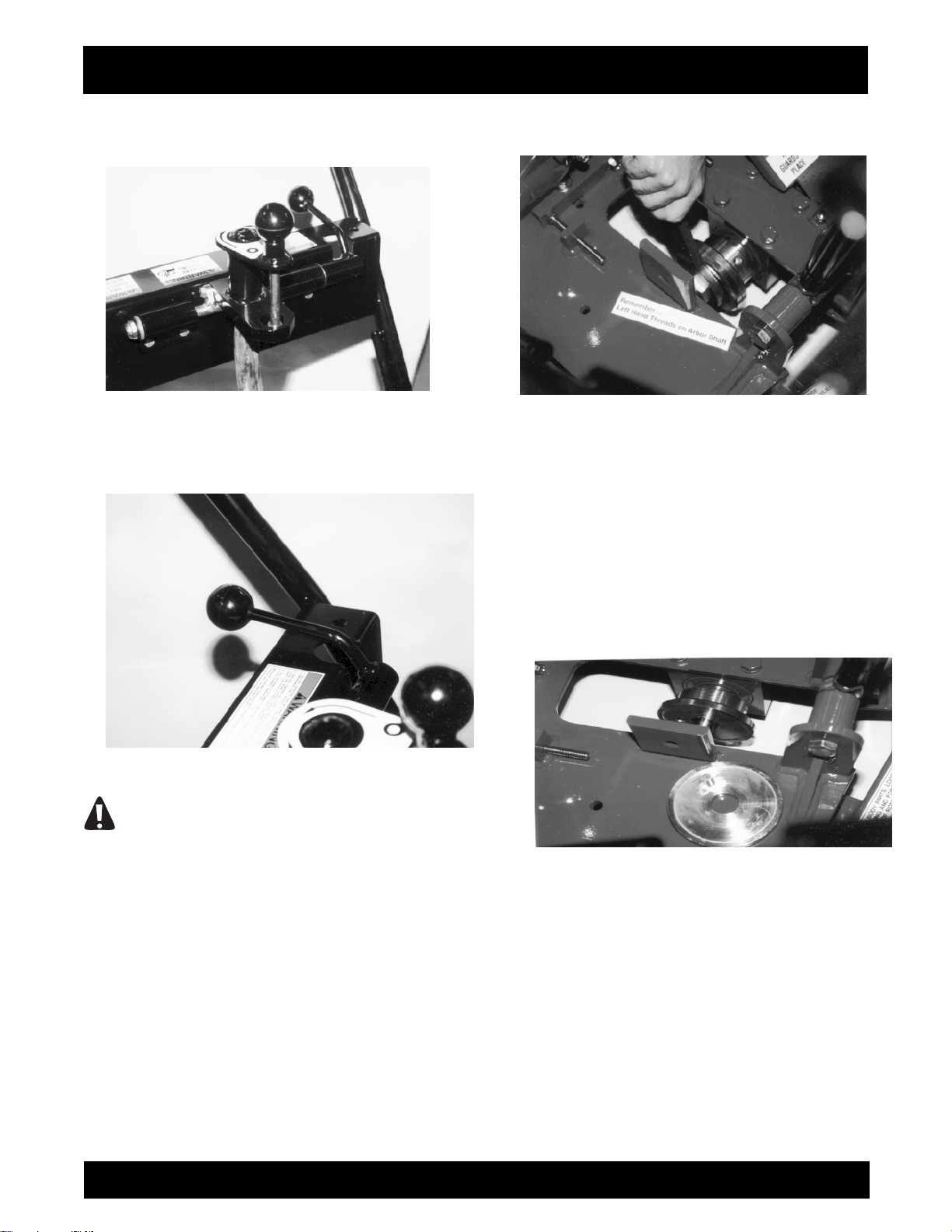
1) Disconnect the spark plug wire.
2) Rotate the height adjustment lever
counterclockwise to raise the blade to its maximum
position above the work surface. FIGURE 1.
RCC130H-CRACK SAW OPERATION AND PARTS MANUAL REV #1 (11/18/04) PAGE 17
Page 18
ASSEMBLY INSTRUCTIONS/OPERATIONS
FIGURE 1
3) Position the quick change height lever over center
to its rear most (up) position. FIGURE 2.
FIGURE 2
DANGER
IMPROPER BLADE POSITION DURING THE
STARTING PROCEDURE CAN ALLOW THE
BLADE TO CONTACT THE WORK SURFACE
BEFORE THE OPERATOR CAN ASSUME A
PROPER OPERATING POSITION. THIS
OCCURRENCE CAN RESULT IN PROPERTY
DAMAGE AND/OR PERSONAL INJURY.
4) Remove the blade guard from the main frame
with the 3/4 inch wrench to expose the arbor shaft.
Using the 1-1/2 inch wrench, remove the hexagon
nut and hub flange from the shaft. The arbor shaft
incorporates left hand threads. FIGURE 3.
FIGURE 3
5) Inspect the hub flange, hub body and arbor shaft
for proper structural integrity. Determine that all
components are free from surface imperfections
including, but not limited to corrosion, cracks,
warpage and material build-ups. Remove any
material build-up from the mating surfaces of the
hub components. Replace any questionable
component with a factory approved replacement
part only. If there are any questions regarding the
suitability of a specific component, contact the
Customer Service Department for assistance
BEFORE utilizing the Crack Saw. There is no
charge for this service. FIGURE 4.
FIGURE 4
6) Inspect the diamond blade for proper structural
integrity as outlined above. If there are any
questions regarding the suitability of a diamond
blade, contact the specific manufacturer or the
Customer Service Department of General
Equipment Company for assistance BEFORE
utilizing it with the Crack Saw. There is no charge for
contacting the Customer Service Department of
General Equipment Company.
7) Proper blade rotation direction is marked on the
side of the blade blank. The Crack Saw is of a down
cut type design as viewed by the operator. The
diamond blade is intended rotate toward the
operator to enhance visibility and overall productivity
RCC130H-CRACK SAW OPERATION AND PARTS MANUAL REV #1 (11/18/04) PAGE 18
Page 19

ASSEMBLY INSTRUCTIONS/OPERATIONS
while following a random crack. Determine the
correct rotation orientation for the diamond blade
and install it on the arbor shaft. FIGURE 5.
8) Reinstall the hub flange on the arbor shaft and
align the stud directly with the corresponding hole in
the blade blank and hub body. The stud is not
designed to drive the diamond blade. FIGURE 6.
DANGER
DO NOT UTILIZE A DIAMOND BLADE THAT
DOES NOT INCORPORATE A DRIVE HOLE FOR
THE HUB FLANGE STUD. DO NOT UTILIZE A
DIAMOND BLADE THAT HAS AN EXCESSIVELY
WORN DRIVE HOLE. DO NOT OPERATE THE
CRACK SAW WITH THE HUB FLANGE
REVERSED FROM ITS NORMAL OPERATING
CONFIGURATION TO ENABLE THE USE OF A
DIAMOND BLADE WITHOUT A DRIVE HOLE.
THE RESULT CAN BE PROPERTY DAMAGE
AND/OR PERSONAL INJURY.
FIGURE 5
FIGURE 6
9) Reinstall the hexagon nut and tighten with the
wrench until the hub flange and body components
exert consistent, firm clamping pressure against the
blade blank. The arbor shaft incorporates left hand
threads, making the hexagon nut semi selftightening against the hub and blade.
10) Reinstall and tighten the Blade Guard to the
main frame.
DANGER
DO NOT OPERATE THE CRACK SAW WITHOUT
THE BLADE GUARD PROPERLY INSTALLED.
OPERATION OF THE CRACK SAW WITHOUT
THE BLADE GUARD PROPERLY INSTALLED
CAN RESULT IN PROPERTY DAMAGE AND/OR
PERSONAL INJURY.
11) Reconnect the engine spark plug wire.
DANGER
UNEXPECTED MACHINE START UP CAN
RESULT IN PROPERTY DAMAGE AND/OR
PERSONAL INJURY.
12) To remove the diamond blade from the arbor
shaft, reverse the steps as outlined above.
TRANSPORTING THE CRACK SAW.
Application: All Models.
The Crack Saw has an operational weight that
prohibits one person from loading and/or unloading it
alone by conventional, physical efforts.
DANGER
DO NOT ATTEMPT TO LIFT THE CRACK SAW
UP INTO A TRANSPORTATION VEHICLE WITH
THE USE OF ONE PERSON ALONE. DO NOT
ATTEMPT TO LOWER THE CRACK SAW FROM
A TRANSPORTATION VEHICLE WITH THE USE
OF ONE PERSON ALONE. LIFT AND/OR LOWER
THE CRACK SAW ONLY BY THE USE OF A
POWER TAILGATE UNIT, A SUITABLE HOIST
UNIT OF PROPER CAPACITY AND/OR
CONFIGURATION OR BY THE USE OF A
RCC130H-CRACK SAW OPERATION AND PARTS MANUAL REV #1 (11/18/04) PAGE 19
Page 20

ASSEMBLY INSTRUCTIONS/OPERATIONS
PROPER QUANTITY OF PERSONNEL IN
PROPER PHYSICAL CONDITION.
The integral lifting bail device(s) can be used to
facilitate lifting by a mechanical device incorporating
a chain and suitable attachment device. The location
of the lifting bail(s) may not always locate the exact
position of the center of gravity for the Crack Saw.
Typical Hoisting Configuration
FIGURE 7 depicts a typical hoisting configuration for
a Crack Saw with a mechanical lifting device.
FIGURE 10
DANGER
EXERCISE EXTREME CAUTION WHEN
UTILIZING A MECHANICAL DEVICE FOR
LIFTING THE CRACK SAW. UTILIZE THE
MECHANICAL DEVICE IN ACCORDANCE TO
BOTH ITS STATED STATIC AND DYNAMIC
LOADING ENVELOPES. DO NOT UTILIZE THE
MECHANICAL DEVICE UNTIL THIS
INFORMATION IS PROPERLY KNOWN AND
UNDERSTOOD BY ALL APPLICABLE
PERSONNEL. FAILURE TO PROPERLY UTILIZE
THE MECHANICAL DEVICE CAN RESULT IN
PROPERTY DAMAGE AND/OR PERSONAL
INJURY.
8) Once on the job site, the Crack Saw can be
lowered to the work surface by reversing the above
steps.
General Transportation Information.
When transporting the Crack Saw on a motor
vehicle, the fuel tank breather vent (if so equipped)
must be completely closed to eliminate the
accidental seepage of fuel and resulting potential fire
and environmental hazards. To minimize the
possibility of damage to the Crack Saw, always
transport in its normal, upright position. All
equipment must be secured in/on vehicles with
suitable strapping or tie-downs. Personnel should
not be transported in the same compartment as
equipment and fuel supplies. Consult applicable
OSHA, AGA, CGA, etc. regulations for the proper
transportation of flammable gases.
STARTING THE RCC130H SERIES GASOLINE
POWERED CRACK SAW ON THE JOB SITE.
1) Position the Crack Saw on a flat and level surface
of firm foundation.
2) Rotate the height adjustment lever
counterclockwise to raise the blade to its maximum
position above the work surface. FIGURE 15.
FIGURE 15
3) Position the quick-change height lever over
center to its rear most (up) position. FIGURE 16.
FIGURE 16
DANGER
IMPROPER BLADE POSITION DURING THE
STARTING PROCEDURE CAN ALLOW THE
BLADE TO CONTACT THE WORK SURFACE
BEFORE THE OPERATOR CAN ASSUME A
PROPER OPERATING POSITION. THIS
OCCURRENCE CAN RESULT IN IMPROPER
DAMAGE AND/OR PERSONAL INJURY.
RCC130H-CRACK SAW OPERATION AND PARTS MANUAL REV #1 (11/18/04) PAGE 20
Page 21

ASSEMBLY INSTRUCTIONS/OPERATIONS
4) Refer to the material supplied by the engine
manufacturer for the correct starting, operation and
stopping procedures.
5) The RCC130H Series Crack Saw is equipped
with a non slip type foot pad to provide additional
stability during the engine starting process. FIGURE
17 depicts a proper operator position for starting the
Crack Saw.
FIGURE 17
6) The RCC130H Series gasoline powered Crack
Saw is not equipped with a centrifugal clutch
assembly. The gasoline engine is directly coupled to
the arbor shaft by a V-belt reduction.
DANGER
AS SOON AS THE ENGINE STARTS, THE
OPERATOR MUST BE IN A POSITION TO
ASSUME DIRECT AND FULL CONTROL OF THE
CRACK SAW. FAILURE TO ASSUME DIRECT
AND FULL CONTROL CAN RESULT IN
PROPERTY DAMAGE AND/OR PERSONAL
INJURY.
7) Allow the engine to properly "warm up" and
operate without the requirement for choking. Check
for excessive machine noise and/or vibration.
DANGER
DO NOT OPERATE A GASOLINE ENGINE IN
CLOSED SPACES WITHOUT PROPER
VENTILATION. GASOLINE ENGINES PRODUCE
CARBON MONOXIDE FUMES. BREATHING
CARBON MONOXIDE FUMES CAN RESULT IN
PROPERTY DAMAGE AND/OR PERSONAL
INJURY. EXCESSIVE LEVELS OF CARBON
MONOXIDE CAN CAUSE DEATH.
8) Stop the engine in accordance with the
instructions as described in the material supplied by
the engine manufacturer.
CAUTION
If the Crack Saw and/or an individual
component/accessory does not appear to be
functioning properly, STOP and do not further
operate the Crack Saw until the proper
corrective action has been completed. If there
are any questions regarding the proper
operation of the Crack Saw, contact the
Customer Service Department BEFORE further
utilization. There is no charge for this service.
OPERATING THE RCC130H CRACK SAW ON
THE JOB SITE.
DANGER
THE SAWING PROCESS PRODUCES
EXCESSIVE NOISE, VIBRATION AND FLYING
DEBRIS. ALL OPERATORS AND WORK
PERSONNEL IN THE VICINITY OF THE CRACK
SAW MUST WEAR APPROPRIATE SAFETY EYE
WEAR AND HEARING PROTECTION DEVICES.
OTHER SAFETY APPAREL AND/OR
PROCEDURES, DEEMED NECESSARY BY
SUPERVISORY PERSONNEL MUST ALSO BE
WORN AND/OR PRACTICED BY ALL
APPROPRIATE PERSONNEL.
DANGER
EXERCISE EXTREME CAUTION WHEN
OPERATING THE CRACK SAW IN THE VICINITY
OF DECK INSERTS, PIPES, COLUMNS,
OPENINGS, LARGE CRACKS, UTILITY OUTLETS
OR ANY OBJECT PROTRUDING FROM THE
SURFACE. CONTACT WITH SUCH OBJECTS
CAN LEAD TO LOSS OF MACHINE CONTROL,
RESULTING IN PROPERTY DAMAGE AND/OR
PERSONAL INJURY.
DANGER
DO NOT OPERATE A GASOLINE ENGINE IN
CLOSED SPACES WITHOUT PROPER
VENTILATION. GASOLINE ENGINES PRODUCE
CARBON MONOXIDE FUMES. BREATHING
CARBON MONOXIDE FUMES CAN RESULT IN
RCC130H-CRACK SAW OPERATION AND PARTS MANUAL REV #1 (11/18/04) PAGE 21
Page 22

ASSEMBLY INSTRUCTIONS/OPERATIONS
PROPERTY DAMAGE AND/OR PERSONAL
INJURY. EXCESSIVE LEVELS OF CARBON
MONOXIDE CAN CAUSE DEATH.
1) The Crack Saw is of a downcut type design as
viewed by the operator. The diamond blade is
intended to rotate toward the operator to enhance
visibility and overall productivity while following a
random crack. The down cut action results in a "self
propelled" effect toward the operator that
substantially enhances machine control and reduces
fatigue as long as the diamond blade does not come
in direct contact with a protruding obstruction from
the floor. Direct contact with such an obstruction can
result in rapid and jerky directional movement of the
machine. In most operating situations, direct contact
with a protruding obstruction from the floor will result
in serious damage to the diamond blade. This
occurrence may not allow the operator to remain in
proper control of the machine.
DANGER
ALWAYS MAINTAIN PROPER CONTROL OF THE
CRACK SAW. IF AN OPERATOR LOOSES
CONTROL OF THE MACHINE, A "RUNAWAY"
CRACK SAW CAN RESULT IN PROPERTY
DAMAGE AND/OR PERSONAL INJURY.
BECAUSE OF THE UNIQUE OPERATING
CHARACTERISTICS OF THE CRACK SAW,
THERE IS NO PROVISION FOR THE ELECTRIC
MOTOR/ENGINE TO AUTOMATICALLY STOP IF
THE OPERATOR FAILS TO MAINTAIN PROPER
CONTROL.
DANGER
WHEN OPERATING THE CRACK SAW ON
ABOVE GROUND FLOOR LEVELS, EXERCISE
EXTREME CAUTION TO PREVENT LOSS OF
CONTROL THAT COULD ALLOW THE MACHINE
AND/OR OPERATOR TO FALL DOWN TO
LOWER LEVELS. SUCH AN OCCURRENCE CAN
RESULT IN PROPERTY DAMAGE AND/OR
PERSONAL INJURY.
2) The crack sawing process is not intended to
require additional weight to be applied to the
machine for the purpose of increasing productivity
and/or stability. No provision for attaching weight is
made.
DANGER
DO NOT OPERATE THE CRACK SAW WITH
ADDITIONAL WEIGHT APPLIED DIRECTLY TO
THE MACHINE TO INCREASE PRODUCTIVITY
RATES AND/OR MACHINE STABILITY.
PROPERTY DAMAGE AND/OR PERSONAL
INJURY CAN RESULT. PRODUCTIVITY AND/OR
STABILITY RELATED PROBLEMS SHOULD BE
DIRECTED TO SPECIFIC MECHANICAL
PROBLEMS WITH THE MACHINE,
OPERATIONAL PROCEDURES AND/OR
SPECIFIC MECHANICAL PROBLEMS
ASSOCIATED WITH THE DIAMOND BLADE.
CONTACT THE CUSTOMER SERVICE
DEPARTMENT FOR ASSISTANCE. THERE IS NO
CHARGE FOR THIS SERVICE.
3) The Crack Saw is designed to be pulled toward
the operator during normal operation to enhance
visibility and overall productivity while the blade
follows a random crack.
CAUTION
Operating the Crack Saw by pushing it forward
will substantially reduce overall productivity and
reduce operator control. The diamond blade will
deposit dust and residue materials under the
feet of the operator. This configuration will not
allow the machine to be utilized with a vacuum
system. This occurrence can also reduce
operator stability on the work surface and lead
to property damage and/or personal injury.
4) Position the Crack Saw over the random crack
with the diamond blade directly above and parallel
with the crack direction. Align the front casters of the
machine parallel with the crack direction to maximize
operator control at the start of the sawing process.
FIGURE 23.
FIGURE 23
RCC130H-CRACK SAW OPERATION AND PARTS MANUAL REV #1 (11/18/04) PAGE 22
Page 23

5) Turn the height adjustment lever clockwise to
lower the blade into the crack until the desired
sawing depth is achieved. Each full turn of the crank
lever will raise/lower the blade approximately 1/16
inch.
6) Following the random crack direction and/or
pattern with the blade is accomplished by viewing
the blade and crack in the louvered opening in the
blade guard. The louvers are intended to provide
protection for the operator in the event that a
diamond segment becomes separated from the
blade blank. Probable causes for such occurrences
are discussed in detail in the Troubleshooting
section of this manual.
a) The geometric design of the louvered blade guard
is intended to provide a high mathematical
percentage of protection for the operator in a normal
operating position as described in this manual. The
mathematical percentage will decrease for operating
positions not described in this manual.
b) In the event of diamond segment separation from
the blade blank, there is a high mathematical
probability that the segment will be thrown forward
against the dust pan located under the main frame
or directly against the forward (non louvered) section
of the blade guard. The manufacturer has
conducted extensive testing to substantiate this
theory. In actual field tests, diamond segments were
purposely separated from the blade blanks through
abusive operational techniques. In all field tests, no
separated diamond segments made direct contact
with the blade guard louvers.
c) In the very low probability that a diamond
segment would make direct contact with the blade
guard louvers, the geometric design has a high
mathematical probability to not allow the segment to
penetrate the vertical plane as defined by the
location of the louvers. The spaces, angle
orientation and number of louvers minimize the
mathematical probability that a segment can
penetrate the vertical plane, exit the louvers and
eventually strike the operator.
d) The geometric configuration of the louvers are
designed to allow for adequate and/or proper
visibility for the operator during the sawing process.
With use, concrete and/or asphalt dust will
accumulate at the bottom of the blade guard
opening. At regular intervals, this material should be
removed to enhance operator visibility during the
sawing process.
ASSEMBLY INSTRUCTIONS/OPERATIONS
DANGER
DO NOT MODIFY THE ORIGINAL OPERATING
CONFIGURATION FOR THE LOUVERS FOR ANY
REASON. MODIFICATIONS TO THE LOUVERS
CAN RESULT IN PROPERTY DAMAGE AND/OR
PERSONAL INJURY.
7) Proper operator posture and stance will enhance
operational safety and overall productivity. FIGURE
24 depicts a proper operator's position. FIGURE 25
depicts an improper operator's position that can
accelerate fatigue, decrease productivity and reduce
safety. The downcut orientation of the diamond
blade will normally produce a "self-propelled" effect
against the operator. This effect is intended to
reduce the operator fatigue associated with the
operation of the machine and to increase overall
productivity.
8) In some operating conditions, it may be
necessary for the operator to apply a resisting force
(push) against the operator handle to counteract the
"self-propelled effect. In some other operating
conditions, it may be necessary for the operator to
apply a force (pull with) to the operator handle in
order to assist the sawing action of the Crack Saw.
FIGURE 24
RCC130H-CRACK SAW OPERATION AND PARTS MANUAL REV #1 (11/18/04) PAGE 23
Page 24

FIGURE 25
The amount and direction of forces to apply to the
operator handle are governed by, but not
necessarily limited to the following factors:
a) Average Random Crack Width.
b) Diamond Blade Saw Width.
c) Sawing Depth.
d) Tensile strength of the material being sawed.
e) Matrix material of the diamond blade segments in
consideration of the aggregate type, amount and/or
hardness contained in the material being sawed.
f) Service condition of the diamond blade segments.
g) Operating RPM speed range for the diamond
blade.
9)For normal job applications, operate the engine at
a maximum, governed speed of 3450 RPM. Consult
the material supplied by the engine manufacturer
and the Specifications section for specific
information. If you have any questions regarding
specific job applications, contact the Customer
Service Department for information. There is no
charge for this service. Additional information can be
obtained from the Masonry and Concrete Saw
Manufacturers Institute, 30200 Detroit Road,
Cleveland, OH 44145-1967.
ASSEMBLY INSTRUCTIONS/OPERATIONS
DANGER
THE CRACK SAW IS DESIGNED FOR THE
ENGINE TO OPERATE AT A MAXIMUM,
GOVERNED SPEED OF 3450 RPM. THIS ENGINE
SPEED AND THE V-BELT REDUCTION SYSTEM
ALLOWS THE DIAMOND BLADE TO OPERATE
WITHIN THE INDUSTRY ACCEPTED RPM SPEED
RANGE. FIELD CHANGES AND/OR
ALTERATIONS MADE TO THE FACTORY SET
ENGINE SPEED RANGE AND/OR V-BELT
PULLEY(S) CAN ALLOW THE DIAMOND BLADE
TO OPERATE OUTSIDE THE INDUSTRY
ACCEPTED RPM SPEED RANGE. THIS
OCCURRENCE CAN RESULT IN PROPERTY
DAMAGE AND/OR PERSONAL INJURY.
10) The wide variety of potential work surface
materials along with the corresponding variety of job
site environments, make it impossible to develop a
standardized operating procedure for the Crack
Saw. Use of the Crack Saw will require constant trial
and error testing until satisfactory results are
achieved. Experience gained over time and common
sense will help minimize the amount of necessary
testing. Many factors will directly affect the operating
parameters and/or techniques utilized for a
specialized job application. Some of these factors
include:
a) Work surface material yield and tensile values. As
a general rule, these values will determine material
removal rate per unit of time. Materials with high
yield and tensile values will characteristically
resist/limit material penetration. For such materials,
the accepted procedure is to make a number of
multiple passes over the work surface rather than
attempt to make a single, deep pass. The net effect
is to actually increase productivity: more material
removed in less time. Other added benefits to this
technique are decreased vibration, less operator
fatigue and increased component service life.
b) The width of the random crack in comparison to
the required cutting width and depth. For example, if
the random crack has an average width of 1/8 inch,
productivity rates will be greater with the use of a 1/4
inch wide blade over that delivered by a 1/2 inch
wide blade. The same analogy can also be used for
the cutting depth. Productivity rates will be greater
for a 1/2 inch deep cut than a 1-inch deep cut.
Deeper cuts also require additional time for the
blade to "clear itself" when following a random crack
pattern.
RCC130H-CRACK SAW OPERATION AND PARTS MANUAL REV #1 (11/18/04) PAGE 24
Page 25

ASSEMBLY INSTRUCTIONS/OPERATIONS
11) The sawing process on many work surface
materials can produce sparks, dust and other
foreign particle contamination.
DANGER
SPARKS PRODUCED BY THE ACTION OF THE
DIAMOND BLADE AGAINST THE WORK
SURFACE (FOR EXAMPLE: STRIKING ANCHOR
BOLTS) MAY COME IN CONTACT WITH
MATERIALS THAT CAN RESULT IN A FIRE
AND/OR EXPLOSION. THIS OCCURRENCE CAN
RESULT IN PROPERTY DAMAGE AND/OR
PERSONAL INJURY.
DANGER
THE CREATION OF DUST AND OTHER FOREIGN
PARTICLE CONTAMINATION FROM THE
OPERATIONAL PROCESS CAN RESULT IN
PROPERTY DAMAGE AND/OR PERSONAL
INJURY. FOR SUCH OPERATING CONDITIONS,
ALWAYS WEAR A NIOSH/MSHA APPROVED
DUST/MIST RESPIRATOR. CONSULT
APPLICABLE OSHA REGULATIONS FOR
SPECIFIC INFORMATION.
12) Dust and other particle contamination can be
controlled by the following methods:
a) The Crack Saw is equipped with a 3 inch outside
diameter vacuum tube adaptor located at the front of
the machine. An industrial type vacuum system can
be attached to the Crack Saw to remove/control dust
and other particle contamination from the work
surface. A hose clamp is sometimes required to
properly secure the vacuum hose to the vacuum
tube. FIGURE 26.
CAUTION
Use of a vacuum system with the Crack Saw will
not totally eliminate or provide 100 per cent dust
and other particle contamination removal from
the atmosphere and work surface. Secondary
dust and other particle contamination removal
procedures from the atmosphere and work
surface will normally be required.
FIGURE 26
DANGER
ALWAYS UTILIZE A VACUUM SYSTEM TO
OPERATE WITHIN THE SPECIFIC JOB SITE
REQUIREMENT. DUST MATERIAL CAN MEET
CLASS II OR CLASS III SPECIFICATIONS OF
THE NATIONAL ELECTRIC CODE® FOR
HAZARDOUS LOCATION CLASSIFICATIONS.
CONSIDERATION MUST ALSO BE GIVEN TO
THE CREATION OF HAZARDOUS TYPE
MATERIALS REQUIRING SPECIFIC DISPOSAL
PROCEDURES. DETERMINE THAT THE
VACUUM SYSTEM IS PROPERLY DESIGNED TO
OPERATE WITHIN THESE ATMOSPHERES.
CONSULT CURRENT NATIONAL ELECTRIC
CODE®, OSHA AND ENVIRONMENTAL
PROTECTION AGENCY REGULATIONS FOR
SPECIFIC INFORMATION.
b) A water stream directed to the blade can be an
effective method of reducing dust effects and
increasing service life at the same time. The optional
RCCWC Wet Sawing Kit can be installed to direct a
continuous stream of water to both sides of the
diamond blade. FIGURE 27. The kit includes a
standard globe type valve to control water feed rates
and is directly coupled to a water hose. Potential
negative effects of this procedure is that the water
and slurry mixture will require additional time for
disposal and proper drying before
crack filling work can be initiated. Under specific
circumstances, the resulting slurry mixture can also
be classified as a hazardous material, requiring
proper disposal procedures.
13) The Crack Saw is equipped with a quick change
height lever designed to raise the diamond blade
clear
RCC130H-CRACK SAW OPERATION AND PARTS MANUAL REV #1 (11/18/04) PAGE 25
Page 26

ASSEMBLY INSTRUCTIONS/OPERATIONS
of the work surface when deployed to its maximum
up position. FIGURE 28.
FIGURE 27
FIGURE 28
The quick-change height lever is intended to provide
a fast method to raise the blade for the following
reasons:
a) When the sawing process is completed for a
random crack, the blade can be quickly raised from
the work surface and the machine moved by the
operator to another random crack on the job site.
Lowering the quick change lever to the full down
position will return the diamond blade to the specific
depth as originally determined by the height
adjustment lever.
FIGURE 29. The quick change height lever is
intended to produce uniform sawing depths for any
specific job application.
FIGURE 29
DANGER
EXERCISE EXTREME CAUTION WHEN MOVING
THE CRACK SAW ON THE JOB SITE WITH THE
POWER SOURCE RUNNING AND THE QUICK
CHANGE HEIGHT LEVER OVER CENTER TO ITS
REAR MOST (UP) POSITION. IN THIS
OPERATING CONFIGURATION, THE DIAMOND
BLADE CAN COME IN DIRECT CONTACT WITH
FOREIGN OBJECTS AND THE WORK SURFACE
ITSELF. THIS OCCURRENCE CAN
SUBSTANTIALLY REDUCE MACHINE CONTROL
AND PRODUCE FLYING OBJECTS, RESULTING
IN PROPERTY DAMAGE AND/OR PERSONAL
INJURY. CAUTION ALL ONLOOKERS
REGARDING THE POSSIBILITY OF FLYING
OBJECTS.
b) If the sawing process overloads the power source
to cause complete stoppage, the diamond blade can
be readily raised by the operator to clear the work
surface before the power source is restarted.
DANGER
DO NOT START AND/OR RESTART THE POWER
SOURCE WITH THE DIAMOND BLADE IN
DIRECT CONTACT WITH THE WORK SURFACE.
BEFORE STARTING AND/OR RESTARTING THE
POWER SOURCE, RAISE THE QUICK CHANGE
HEIGHT LEVER OVER CENTER TO ITS REAR
MOST (UP) POSITION TO ALLOW THE DIAMOND
BLADE TO COMPLETELY CLEAR THE WORK
SURFACE. IF THIS ACTION DOES NOT
COMPLETELY RAISE THE DIAMOND BLADE
FROM THE WORK SURFACE, DETERMINE THAT
RCC130H-CRACK SAW OPERATION AND PARTS MANUAL REV #1 (11/18/04) PAGE 26
Page 27

ASSEMBLY INSTRUCTIONS/OPERATIONS
A BLADE OF PROPER DIMENSIONS IS BEING
UTILIZED. IF THERE ARE ANY QUESTION
REGARDING PROPER BLADE DIMENSIONS FOR
USE WITH THE CRACK SAW, CONTACT THE
CUSTOMER SERVICE DEPARTMENT FOR
SPECIFIC INFORMATION. THERE IS NO
CHARGE FOR THIS SERVICE.
DANGER
STARTING AND/OR RESTARTING THE CRACK
SAW WITH THE DIAMOND BLADE IN DIRECT
CONTACT WITH THE WORK SURFACE CAN
SUBSTANTIALLY REDUCE MACHINE CONTROL,
RESULTING IN PROPERTY DAMAGE AND/OR
PERSONAL INJURY.
14) Generally speaking, the majority of random
crack patterns follow a predominantly straight line
with no more than 20˚ variance from an imaginary
center line. FIGURE 30. These random crack
patterns are easily sawed to the required widths and
depths by the properly described diamond blades.
FIGURE 30
However, there are many instances where the
random crack pattern follows perpendicular (90˚) to
more obtuse (91˚ to 179˚) angles. FIGURE 31.
These angles will generally not allow the Crack Saw
to properly follow the resulting patterns without
significantly reducing operator control, overall
productivity and causing severe damage the
diamond blade.
FIGURE 31
These types of patterns can be properly sawed by a
multiple step process. A segment of the crack is first
sawed by the described process (FIGURE 32) and
the machine repositioned by the described
procedure to saw the intersecting segment. FIGURE
33. This procedure can be repeated as necessary
by the geometry of the specific random crack
pattern. Following this procedure is especially
important when deep (greater than 1/2 inch) saw
cuts are required for proper crack filling methods. By
utilizing this operating procedure, intricate random
crack patterns can be properly sawed while
maximizing operator control, overall productivity and
extending blade service life.
FIGURE 32
RCC130H-CRACK SAW OPERATION AND PARTS MANUAL REV #1 (11/18/04) PAGE 27
Page 28

FIGURE 33
DANGER
IMPROPER SAWING PROCEDURES FOR ANY
SPECIFIC RANDOM CRACK CAN
SUBSTANTIALLY REDUCE OPERATOR
CONTROL, OVERALL PRODUCTIVITY AND
CAUSE SEVERE DIAMOND BLADE DAMAGE,
RESULTING IN PROPERTY DAMAGE AND/OR
PERSONAL INJURY.
15) Increased productivity rates can usually be
achieved in intricate random crack patterns with the
use of a wider diamond blade. FIGURE 34.
FIGURE 34
16) Normal usage of the Crack Saw will allow the
build-up and accumulation of work surface materials
on interior surfaces. It is highly recommended that
both the interior and exterior surfaces be properly
cleaned after the completion of each usage.
ASSEMBLY INSTRUCTIONS/OPERATIONS
CAUTION
Failure to properly clean the interior surfaces of
the Crack Saw can result in dried material buildup and accumulation directly affecting bearing
and V-Belt service life.
DANGER
EXERCISE EXTREME CAUTION WHEN
UTILIZING ANY SOLVENT TO REMOVE
ACCUMULATED MATERIALS FROM THE
SURFACES OF THE MACHINE AND RELATED
COMPONENTS. MANY SOLVENTS ARE
FLAMMABLE. DO NOT SMOKE OR INTRODUCE
FLAME IN THE WORK AREA. PROVIDE
ADEQUATE VENTILATION AND WEAR PROPER
SAFETY APPAREL.
DANGER
PROPERLY DISPOSE OF ALL ACCUMULATED
MATERIALS PER OSHA AND ENVIRONMENTAL
PROTECTION AGENCY CODES AND
REGULATIONS. MANY ACCUMULATED
MATERIALS CAN BE CLASSIFIED AS
HAZARDOUS AND REQUIRE PROPER
DISPOSAL PROCEDURES. CONTACT THE
APPLICABLE GOVERNMENT AND/OR PRIVATE
AGENCIES FOR SPECIFIC INFORMATION.
17) On job applications where the work process
creates a considerable amount of loose material, it
can become almost impossible to determine proper
cutting direction for the blade and the extent of work
already accomplished. The problem can be
compounded if a vacuum system is not utilized.
Loose material should be removed by sweeping or
other, appropriate processes and the Crack Saw
utilized until conditions again warrant removing the
accumulated material.
RCC130H-CRACK SAW OPERATION AND PARTS MANUAL REV #1 (11/18/04) PAGE 28
Page 29

ASSEMBLY INSTRUCTIONS/OPERATIONS
STOPPING THE RCC130H SERIES GASOLINE
POWERED CRACK SAWS.
1) Position the quick change height lever over center
to its rear most (up) position.
2) Stop the Crack Saw by moving the engine throttle
control lever to the idle speed position. Turn the
ignition switch located on the engine to the OFF
position. Consult the material supplied by the engine
manufacturer for specific information.
OPERATIONAL PARAMETERS AND
TECHNIQUES FOR THE RCC130H SERIES
CRACK SAW.
Basic definitions.
There are very few aspects of the pavement
maintenance industry that all members, including
contractors, engineers, researchers and government
agencies can agree on except the inevitability of
cracks forming in all types of pavements. To
properly address the crack repair procedures,
contractors must have a basic understanding of why
crack repair is beneficial, crack types to address and
the repair materials and methods available.
A basic understanding of the difference between
crack filling and crack sealing and the working
knowledge to understand which one is appropriate
for a specific job application is essential for any
pavement maintenance contractor.
An industry accepted definition of crack filling is the
placement of materials into cracks to reduce water
intrusion and reinforce the adjacent pavement.
Crack sealing is the placement of specialized
materials either above or into working cracks to
prevent the intrusion of water and incompressibles
such as sand, aggregate and dirt.
Why Do It at All?
Crack sealing is used as a first line of defense
against the deterioration of pavement because of its
inherent benefits:
a) It protects the base and sub-base. A good
pavement requires a base and sub-base of high
structural integrity. Effective crack sealing
procedures eliminate water from entering and
weakening these areas. The resulting weakness
can result in the loss of structural support, which can
then further result in the formation of additional
cracks and settling around the crack area.
b) It preserves the pavement adjacent to the
cracking. Cracks that are properly cleaned and
sealed contain filler materials that firmly adhere to
the crack sides during times of both expansion and
contraction. Without the addition of these filler
materials, the adjacent pavement would have
increased exposure to the elements, resulting in
increased oxidation of the binder, hardening and
secondary cracking along the main crack.
c) It eliminates the damaging effects of
incompressibles such as sand, aggregate and dirt.
When these materials get into a crack they can
restrict crack closure during periods of warm
weather. The resulting compressive stresses at the
faces can create spalling and loosening. In some
highly oxidized pavements these stresses can even
create pavement lipping, which is the upheaval of
pavements at their transverse cracks.
d) It extends pavement life. Sealing procedures
allow the contractor to effectively exert control over
the base and sub-base conditions, pavement
interference and crack growth, thereby extending
the pavement's service life.
Types of Cracks.
There are several basic types of cracks:
a) Reflective. This type of crack appears primarily in
resurfacing projects, although it can also occur in a
new pavement surface. Reflective cracks occur
when an existing crack or joint in the underlying
pavement structure reflects upward through the
surface.
b) Joint. A joint is the edge of the individual paving
pass made during construction. Such construction
joints usually have a lower density than the
remaining material. When the placed mats do not
bond properly (for any number of reasons), joint
cracks can appear.
c) Slippage. Slippage cracks are usually crescent
shaped and are created by heavy traffic that is either
stopping, turning or climbing a hill. Resultant
stresses can cause a bond failure between upper
and lower pavement layers. The open end of the U
shaped crack always points in the direction of the
applied force.
d) Thermal. All pavements expand and contract due
to temperature variations. This movement can
create cracks. To better allow for movement,
pavements need to be constructed with the correct
percentage of air voids, which provide for internal
stress relief. When the air void percentage is not
correct, thermal cracks appear.
RCC130H-CRACK SAW OPERATION AND PARTS MANUAL REV #1 (11/18/04) PAGE 29
Page 30

ASSEMBLY INSTRUCTIONS/OPERATIONS
e) Fatigue or alligator. Over time, as a pavement
surface ages, it becomes more rigid and has less
ability to tolerate vertical load deflections. This
occurrence creates a tension and pulling apart in the
pavement and results in alligator type cracking.
Such cracking can also occur from improper
structural capacity and aging. It is generally
recommended that alligatored areas be removed
and replaced rather than be filled or sealed.
f) Block. This type of crack forms a square pattern,
with cracks intersecting at approximate right angles.
A common cause of block cracks on asphalt
pavements is a lack of traffic, which constantly
kneads the pavement and keeps it flexible. Other
causes can include excessive air voids in the
material.
g) Edge. Edge cracks appear only parallel to and
within usually 18 inches of the pavement edge.
Cause can include substandard base, lack of
shoulder support, inadequate drainage or damage
caused by frost.
Equipment and Materials.
Pavement contractors can select from a wide variety
of hot or cold applied materials to seal cracks. Unlike
cold materials, hot applied sealers are first prepared
prior to application. The standard method is a double
boiler kettle, which consists of an inner chamber that
contains and agitates the sealant material and an
outer chamber serving as the heat source.
Heated sealers include rubberized asphalt, low
modulus rubberized asphalt, fiberized asphalt and
asphalt rubber. Cold applied materials are usually
comprised of a self leveling silicone and modified
emulsions.
When making a material selection, the pavement
contractor must consider many factors. It is critical
that the material be placed efficiently and deliver
satisfactory performance given the related
environmental factors. Other significant factors
include preparation and cure times, adhesiveness to
the crack sides, cohesiveness in the crack center,
resistance to softening and flow, aging and
weathering.
Preparation and Application.
The primary purpose of the Crack Saw is to produce
a proper configuration in the crack area for the
placement of the sealing material. The exact
configuration is dependent upon many factors
including crack type, pavement downtime and
budget restrictions. There are numerous
configurations, although all can be grouped into four
general classifications:
a) Flush fill. The material is simply dispensed into an
existing unsawed crack and the excess struck off.
b) Reservoir. Material is placed only within the
confines of a sawed crack, either flush with or
slightly below the pavement surface.
c) Overband. Material is placed into and over an
unsawed crack and shaped into either a band aid
configuration (3 to 5 inches wide and 1/8 inch thick)
or given a slight cap.
d) Combination. Material is placed into and over a
sawed crack, then is shaped by squeegee into a
band centered over the crack reservoir.
The configuration of the random crack ultimately
determines the specific type and/or quantity of
material utilized in the process.
RCC130H-CRACK SAW OPERATION AND PARTS MANUAL REV #1 (11/18/04) PAGE 30
Page 31

MAINTENANCE/SERVICE
Maintenance/Service
PREVENTATIVE MAINTENANCE CHECK LIST.
The normal operation of the Crack Saw produces
extreme dirt and dust, along with levels of random
vibration. Before operating the Crack Saw, the
following service list should be accomplished. This
list is for reference only and is not intended to be all
inclusive. Other subject areas can be added at the
discretion of the owner(s) and/or operator(s):
1) Check all fasteners for proper torque values. If a
fastener requires retorquing, consult a torque chart
for proper value. Properly discard and replace any
worn fastener with a factory approved, replacement
part.
2) Check the V-belts for wear. Adjust or replace as
necessary. Check pulleys for wear and proper
alignment. Many loose materials created as a result
of operating processes can be extremely abrasive.
3) Keep the Crack Saw clean. Wash the unit after
each use. Keep loose materials from accumulating
around engine cooling fins. Determine that the
interior sections of the frame are free of material
build-up. Such a build-up can restrict the operating
process and present a potential safety hazard.
Clean and remove any material build-up from the
Crack Saw after each use.
4) Engine service life can be extended with proper
air cleaner maintenance. Consult the material
supplied by the engine manufacturer for specific
information.
5) Check for proper oil level. Always use clean, high
quality engine oil. Change oil as required. Consult
the material supplied by the engine manufacturer for
specific information.
6) Remove material accumulations from the exterior
surfaces of the electric motor. The electric motor is a
totally enclosed, fan cooled (TEFC) design. Keep
the fan fins clear of material accumulations to
enhance air flow over the motor exterior for cooling
purposes.
DANGER
DO NOT PERFORM PREVENTATIVE
MAINTENANCE CHECKS WITH THE ENGINE
RUNNING. DISCONNECT THE SPARK BEFORE
PERFORMING ANY MAINTENANCE
RECONNECT THE SPARK PLUG BEFORE
IMPROPER PROCEDURES CAN RESULT IN
PROPERTY DAMAGE AND/OR PERSONAL
INJURY.
CHECKING V-BELT TENSION AND ALIGNMENT.
Application: All Models.
Proper V-belt tension and alignment is essential for
smooth transmission of horsepower and extended
service life. Improper tension and alignment will
accelerate V-belt wear and contribute to decreased
productivity. The V-belt is tensioned at the factory
with the maximum recommended tension force.
Check the belt tension at least two times during the
first day of operation as there will normally be a
rapid decrease in belt tension until it has been run
in. Check the belt tension every eight hours of
operation thereafter and maintain tension within the
recommended range. The correct operating tension
for a V-belt drive is the lowest tension at which it will
not slip under peak load conditions.
Tools Required:
1 each, 16 inch minimum length straightedge.
1 each, 10 lbs minimum capacity, tension scale or
belt tension tool.
1) Position the Crack Saw on a suitable work bench
with the V-belts approximately at waist level.
2) Disconnect the engine spark plug wire.
3) Remove the belt guard from the main frame.
Clean the inside of the belt guard with an
appropriate solvent. Check for signs of wear and
damage. Secure in a proper storage area.
CAUTION
Observe all applicable safety precautions for the
solvent.
4) Check the belt tension using the spring scale or
belt tension tool midway between the engine/motor
pulley and the arbor shaft pulley. Belt tension should
measure approximately 0.22 inch at 3-1/4 to 4-3/8
lbs. measured force range. FIGURE 35. If tension is
within specifications, proceed to Step 5. If tension is
not within specifications, refer to INSTALLING A
REPLACEMENT V-BELT for specific information.
RCC130H-CRACK SAW OPERATION AND PARTS MANUAL REV #1 (11/18/04) PAGE 31
Page 32

FIGURE 35
5) Belt alignment is checked with the straightedge.
Place the straightedge squarely against the arbor
shaft pulley. Properly aligned pulleys should also
place the straightedge squarely against the
engine/motor pulley. Remove the straightedge and
rotate the engine/motor pulley 120 degrees.
Recheck alignment with the straightedge. Repeat
the process until the engine/motor pulley is rotated a
full 360 degrees. Maximum allowable misalignment
is + - 1/32 inch. If pulley alignment is not within
specifications, refer to INSTALLING A
REPLACEMENT V-BELT for specific information.
FIGURE 36.
FIGURE 36
6) Reinstall the belt guard to the main frame.
Determine that all safety related decals affixed to the
belt guard are fully readable. If any decal is not fully
readable, replace with a factory approved,
replacement part only.
7) Reconnect the engine spark plug wire. Position.
MAINTENANCE/SERVICE
DANGER
UNEXPECTED MACHINE START UP CAN
RESULT IN PROPERTY DAMAGE AND/OR
PERSONAL INJURY.
INSTALLING A REPLACEMENT V-BELT OR
PULLEY.
Tools Required:
2 each, 9/16 wrenches.
1 each, 5/32 Allen wrench.
1 each, 16 inch minimum length straightedge.
1 each, 10 lbs minimum capacity, tension scale or
belt tension tool.
Parts Required:
2 each, PN BX34 V-belt (if required).
1 each, PN CS8-0260 pulley assembly (if required).
1 each, PN CS8-0270 pulley assembly (if required).
1) Position the Crack Saw on a suitable work
surface with the V-belts approximately at waist level.
2) If the Crack Saw is powered by an engine,
disconnect the spark plug wire. If powered by an
electric motor, disconnect the extension cord or
Crack Saw from the power source. If the Crack Saw
is powered with a Propane converted engine, the
Propane cylinder must be removed from the main
frame to better facilitate the maintenance process.
Determine that the Propane cylinder valve is fully
closed before uncoupling the hose. Secure in a
proper storage area. Using the 9/16 inch wrenches,
remove the belt guard from the main frame. Clean
the inside of the belt guard with an appropriate
solvent. Check for signs of wear and damage.
Secure in a proper storage area.
RCC130H-CRACK SAW OPERATION AND PARTS MANUAL REV #1 (11/18/04) PAGE 32
Page 33

CAUTION
Observe all applicable safety precautions for the
solvent.
3) Remove the belt guard from the main frame.
Clean the inside of the belt guard with an
appropriate solvent. Check for signs of wear and
damage. Secure in a proper storage area.
4) Using the 9/16 inch wrenches, loosen the
engine/motor mounting capscrews.
5) With the same wrenches, rotate the engine takeup capscrews counterclockwise to loosen the Vbelts and allow the engine/electric motor to slide
toward the operator handle. FIGURE 37.
6) Remove the worn V-belts. Inspect the
engine/electric motor and arbor shaft pulleys for
wear and damage. Install the replacement belts, PN
BX34 in pairs. The Crack Saw utilizes two V-belts.
Always install replacement belts in matched pairs.
Never replace just one of the V-belts.
CAUTION
Do not operate the Crack Saw with only one Vbelt installed. One V-belt is not capable of
transmitting proper horsepower and torque
levels to the arbor shaft.
a) Do not install replacement belts if the pulleys
have excessively worn grooves. Such pulleys should
be replaced to insure proper belt fit. Operating the Vbelts in worn pulley grooves will accelerate wear,
reduce horsepower and torque levels and
significantly reduce component service life.
b) A V-belt should never be forced over a pulley.
More belts are broken from this cause than from
actual failure in service.
c) Keep the belts as clean and free of foreign
material as possible. Do not use belt dressing.
FIGURE 37
MAINTENANCE/SERVICE
7) Tighten the engine/electric motor attachment
capscrews until they just begin to apply tension to
the engine/electric motor. DO NOT OVER
TIGHTEN. Alternately tighten the take-up capscrews
until slight tension is applied to the V-belt.
8) Belt alignment is checked with the straightedge.
Place the straightedge squarely against the arbor
shaft pulley. Properly aligned pulleys should also
place the straightedge squarely against the
engine/electric motor pulley. Remove the
straightedge and rotate the engine pulley 120
degrees. Recheck the alignment with the
straightedge. Repeat the process until the
engine/electric motor pulley has been rotated a full
360 degrees. Maximum allowable misalignment is +1/32 inch. FIGURE 38.
FIGURE 38
9) Apply increased belt tension by progressively
tightening the take-up capscrews against the
engine/electric motor.
a) Recheck V-belt alignment.
b) Check belt tension with the spring scale or belt
tension tool midway between the engine/electric
motor and arbor shaft pulleys. Belt deflection should
measure approximately .20 inch at 4 to 5-1/2
pounds force. FIGURE 39.
FIGURE 39
RCC130H-CRACK SAW OPERATION AND PARTS MANUAL REV #1 (11/18/04) PAGE 33
Page 34

MAINTENANCE/SERVICE
c) If the belt tension and alignment are within
specifications, torque the engine/electric motor
attachment capscrews to 35 ft lbs (47 N.m).
d) Recheck V-belt tension and alignment.
10) Reinstall the belt guard to the main frame. Install
the flat washers and self locking hexagon nuts.
Determine that all safety related decals affixed to the
belt guard are fully readable. If any decal is not fully
readable, replace with a factory approved
replacement part only.
11) Reconnect the engine spark plug wire.
DANGER
UNEXPECTED MACHINE START UP CAN
RESULT IN PROPERTY DAMAGE AND/OR
PERSONAL INJURY.
INSTALLING REPLACEMENT BEARINGS ON
THE ARBOR SHAFT.
Application: All Models.
Tools Required:
2 each, 9/16 inch wrenches.
1 each, 3/4 inch wrench.
1 each, 5/32 inch Allen wrench.
1 each, pliers for large, external type snap rings.
1 each, shop press.
Parts Required:
2 each, PN 5208-2RS sealed bearings.
1 each, container of bearing and shaft locking grade,
anaerobic adhesive/sealant.
1 each, PN 5160-156 snap ring (if required).
1 each, PN CS8-0230 bearing block (if required).
1 each, PN CS8-0030 arbor shaft (if required).
1) Position the Crack Saw on a suitable work
surface with the V-belt approximately at waist level.
2) If the Crack Saw is powered by an engine,
disconnect the engine spark plug wire. If powered by
an electric motor, disconnect the extension cord or
Crack Saw from the power source. If the Crack Saw
is equipped with a Propane converted engine, the
Propane cylinder must be removed from the main
frame to better facilitate the maintenance process.
Determine that the Propane cylinder is fully closed
before uncoupling the hose. Secure in a proper
storage area.
3) Using the 9/16 inch wrenches, remove the belt
guard from the main frame. Clean the inside of the
belt guard with an appropriate solvent. Check for
signs of wear and damage. Secure in a proper
storage area.
CAUTION
Observe all applicable safety precautions for the
solvent.
4) Remove the V-belt and arbor shaft pulley. Refer
to INSTALLING A REPLACEMENT V-BELT OR
PULLEY for specific information. Remove the blade
guard from the main frame. Clean the interior and
exterior surfaces of the blade guard with an
appropriate solvent. Check for signs of wear and
damage.
5) Using the 3/4 inch wrench, remove the bearing
block/arbor shaft from the main frame. Clean the
arbor shaft/bearing block assembly with an
appropriate solvent. Check for signs of wear and
damage.
6) Position the bearing block/arbor shaft assembly
on a suitable work surface. Use the snap ring pliers
to remove the snap ring. FIGURE 40.
CAUTION
Wear safety glasses and other appropriate safety
apparel when removing the snap ring or
performing any work with an arbor press.
Caution all onlookers about the possibility of
flying debris and personal injury.
7) Using the Allen wrench, remove the Allen screws
that retain the hub body to the arbor shaft. If the hub
body does not freely remove itself from the arbor
shaft, position the assembly in a suitable arbor
press. FIGURE 41. The hub can be removed by
pressing the hub body from the arbor shaft. As the
hub body separates from the arbor shaft, the arbor
shaft/bearing block assembly can fall directly to the
work surface.
RCC130H-CRACK SAW OPERATION AND PARTS MANUAL REV #1 (11/18/04) PAGE 34
Page 35

MAINTENANCE/SERVICE
FIGURE 40
FIGURE 41
CAUTION
Exercise extreme caution when pressing the hub
body from the arbor shaft/bearing block
assembly. Improper activities can result in the
components striking body parts, resulting in
property damage and/or personal injury.
8) Position the arbor shaft assembly in a suitable
arbor press with the snap ring shoulder facing down.
Determine that the bearing block face is properly
supported. The outside diameter of the bearing must
be clear for axial movement. Press the arbor shaft
assembly from the bearing block. FIGURE 42.
Reposition the assembly and press the remaining
bearing from the bearing block. FIGURE 43.
FIGURE 42
FIGURE 43
9) Clean and inspect the arbor shaft and bearing
block for wear and damage. Replace any
questionable component with a factory replacement
part only.
10) Clean the outside bore diameter of the
replacement bearing with an appropriate solvent.
Apply a suitable amount of anaerobic
adhesive/sealant to the outside diameter of the
bearing. Determine that the outside diameter of the
bearing will absorb the thrust from the pressing
process. The inside bore of the bearing should not
receive any direct thrust force. Press the
replacement bearing into the bearing block until it
seats itself against the flange.
RCC130H-CRACK SAW OPERATION AND PARTS MANUAL REV #1 (11/18/04) PAGE 35
Page 36

MAINTENANCE/SERVICE
FIGURE 44.
FIGURE 45
11) Clean the bearing journal areas of the arbor
shaft with an appropriate solvent. Apply a suitable
amount of anaerobic adhesive/sealant to the bearing
journal area located near the snap ring groove.
Press the arbor shaft into the replacement bearing
until it seats itself against the inner race. FIGURE
45.
12) Clean the inside and outside bore of the second
replacement bearing with an appropriate solvent.
Apply a suitable amount of anaerobic
adhesive/sealant to the inside and outside bore.
Install the replacement bearing over the arbor shaft.
Determine that both the inside and outside bores of
the bearing will absorb the thrust from the pressing
process. Press the replacement bearing into the
bearing housing until it seats itself against the
flange. This procedure will minimize the potential for
improper bearing preloading. FIGURE 46.
FIGURE 46
13) Reinstall the snap ring into the snap ring groove
on the arbor shaft.
RCC130H-CRACK SAW OPERATION AND PARTS MANUAL REV #1 (11/18/04) PAGE 36
Page 37

MAINTENANCE/SERVICE
CAUTION
Wear safety glasses and other appropriate safety
apparel when removing the snap ring or
performing any work with an arbor press.
Caution all onlookers about the possibility of
flying debris and personal injury.
14) Rotate the arbor shaft by hand to determine the
amount of bearing preloading created as a result of
the installation process.
Properly installed replacement bearings should
rotate without excessive friction, drag and/or "rough
spots". If these symptoms occur after assembly, the
bearings were improperly supported when pressed
into the bearing block. The resulting thrust placed
upon the bearing exceeded the static capacity.
Bearing operating with these characteristics will
deliver minimal service life and be prone to
premature failure.
15) Inspect the hub body drive key and hub body for
wear and/or damage. Replace any questionable
component with a factory replacement part only.
Reinstall the hub body drive key into the arbor shaft.
Reinstall the hub body to the arbor shaft until it fully
seats against the inside bore of the bearing.
Reinstall the two Allen screws into the hub body and
properly torque.
16) Inspect the arbor shaft drive key and arbor shaft
pulley for wear and/or damage. Replace any
questionable component with a factory replacement
part only. Reinstall the arbor shaft pulley drive key
into the arbor shaft. Reinstall the arbor shaft pulley.
Do not torque the Allen screws at this time. The
Allen screws will be tightened after determining that
the engine/electric motor and arbor shaft pulleys are
in proper alignment. See Step 19.
17) Reassemble the bearing block to the main
frame. Determine that the arbor shaft rotates
perpendicular to both the vertical and horizontal
planes as defined by the direction of machine travel.
18) Follow the instructions as outlined for
INSTALLING A REPLACEMENT V-BELT OR
PULLEY to complete the assembly of the pulleys, Vbelts and belt guard.
19) Reconnect the engine spark plug wire .
DANGER
UNEXPECTED MACHINE START UP CAN
RESULT IN PROPERTY DAMAGE AND/OR
PERSONAL INJURY.
LUBRICATION REQUIREMENTS.
Application: All Models.
Parts Required:
1 each, standard grease gun filled with one of the
following: ESSO Beacon 325, Shell Alvania #2,
Chevron SRI, or equivalent.
1 each, container of dry film lubricant.
1) Lubricate the rigid caster wheel bearing with a dry
film lubricant only. Dry film lubricants dry
immediately upon contact. Use sparingly. Excess
lubricant will attract the fine grained, powdered
materials described in this manual and directly affect
bearing service life.
CAUTION
Do not lubricate the rigid caster wheels with any
type of grease material. Grease will attract
foreign material accumulations that can
accelerate bearing wear.
2) The arbor shaft is supported by extra capacity,
ball bearings. These bearings are lubricated at the
time of manufacture and do not require additional
servicing when placing the unit in initial service or
during their normal service life. During the first few
hours of service, lubrication material may seep from
the bearings. This should not be a cause for
immediate concern.
3) The swivel wheel casters are sealed to minimize
the potential for dust contamination. Lubricate the
swivel caster wheels with the grease gun. Use
sparingly. Excess lubricant will attract the fine
grained, powered materials described in this manual
and directly affect bearing service life.
4) Do not apply belt dressing materials to the V-belts
for the purpose of minimizing slippage. These
products typically attract foreign material
accumulations that can accelerate component wear.
Excessive V-belt slippage can be eliminated with
proper V-belt tension and alignment.
RCC130H-CRACK SAW OPERATION AND PARTS MANUAL REV #1 (11/18/04) PAGE 37
Page 38

ENGINE SERVICE.
RCC130H Crack Saw.
Consult the material supplied by the engine
manufacturer for specific service and maintenance
information regarding:
1) Muffler
2) Spark Plug
3) Air Filter System
4) Carburetor Adjustment
5) Ignition System
6) Short and Long Term Storage
7) Maximum Governor Speed
8) Emission Standards
Keep this information stored with the Operator's
Manual for the Crack Saw so it will always be
available for use when the engine requires service
or maintenance. A properly maintained engine will
add considerably to the service life and overall
productivity of the Crack Saw.
MAINTENANCE/SERVICE
RCC130H-CRACK SAW OPERATION AND PARTS MANUAL REV #1 (11/18/04) PAGE 38
Page 39

TROUBLESHOOTING
Troubleshooting
ENGINE FAILS TO START
Ignition switch in OFF or cut off position. Place
switch in the ON position or move throttle control
lever to the ignition operational position.
Incorrect carburetor/fuel ignition system adjustment.
See Service section.
Air filter blocked. See Service section.
Ignition wire to spark plug loose or disconnected.
Reconnect.
Fuel supply exhausted. Refill the fuel tank.
ENGINE LOSES POWER
Incorrect carburetor/fuel injection adjustment. See
Service section.
Water in fuel supply. Drain and replace fuel.
Excessive carbon accumulation in combustion
chamber. See Service section.
Fuel tank breather vent closed (if so equipped).
Open vent.
Air filter system blocked. See Service section.
OPERATIONAL PROBLEMS.
DANGER
ALWAYS UTILIZE DIAMOND BLADES IN
COMPLIANCE WITH ANSI B7.1, ANSI B7.5
AND/OR LATEST REVISION(S) AND
APPLICABLE OSHA REGULATIONS. IMPROPER
USE OF DIAMOND BLADES CAN RESULT IN
PROPERTY DAMAGE AND/OR PERSONAL
INJURY.
Copies of ANSI B7.1 and B7.5 for review and
education purposes can be obtained from the
American National Standards Institute, 1430
Broadway, New York, NY, 10018. Copies of the
applicable OSHA regulations governing the use of
powered equipment and diamond blades can be
obtained from your nearest OSHA office.
DIAMOND SEGMENT LOSS
a) The Crack Saw is not being held firmly by the
operator, causing the blade to twist or jam in the
work surface. Hold the Crack Saw firmly.
b) Overheating due to inadequate supply of coolant
(air or water). This is usually accompanied by
discolorations which appear on the blade blank in
the area of the segment loss. If wet sawing, provide
adequate water flow to both sides of the blade.
Determine that no water line blockage exists. If dry
sawing, periodically allow the blade to run out of the
saw cut for up to 20 seconds for every minute of
sawing. This will allow the blade to properly cool
before resuming sawing operations .
c) The blade blank wears thin as a result of
undercutting by abrasive fines generated by the
sawing process. The blade blank wears to a knife
edge which weakens the blank and causes a
segment to separate. If the fines are highly abrasive,
wear resistant blanks should be utilized to retard the
undercutting phenomenon. Inspect the blades
periodically during usage for this occurrence. If wet
cutting, allow for ample water to flush the fines out of
the saw cut.
d) Improper clamping action by the arbor shaft hub
body and hub flange causes the blade to flutter in
the cut or fail to support the blade in proper
alignment. Always clean foreign material
accumulations from the flange surfaces. Replace the
flanges if they become bent or deformed with factory
approved replacement parts only.
e) The blade can be too hard for the specific
material being sawed, causing excessive dullness
and segment separation due to impact loads and/or
fatigue. This occurrence can also be the direct
cause of frictional heat which can melt the brazing
filler material that secures the segments to the blade
blank. Use a proper blade specification for the
material being cut. Match the segment matrix
composition to the specific aggregate material being
sawed.
f) The blade rotation while sawing is out of round
(not concentric), resulting in direct impulse loads
being applied to the segments. Replace worn
machine components including bearings and arbor
shaft.
g) Improper blade rotational speed which produces
excessive pressure on the segments and
subsequent failure of the brazed/welded joint, blade
blank or segment itself. Determine that the blade is
being operated within the industry recommended
RPM speed range. Engine RPM should be checked
RCC130H-CRACK SAW OPERATION AND PARTS MANUAL REV #1 (11/18/04) PAGE 39
Page 40

TROUBLESHOOTING
periodically with an electronic tachometer to ensure
proper operational speed for the blade.
UNEVEN SEGMENT WEAR
a) If wet sawing, insufficient water flow to one side of
the blade which effectively reduces the side
clearance. Flush the water system. Determine that
water is being adequately and equally distributed to
both sides of the blade.
b) Worn machine components. Determine that
machine components, including bearings, belts and
the arbor shaft are not excessively worn and
requiring replacement. Determine that the engine
runs smoothly to prevent harmonic vibrations which
can result in the blade impacting the work surface
with impulse type loads.
c) Saw head is misaligned. Periodically check saw
head for squareness in both vertical and horizontal
planes.
SEGMENT CRACKS
a) Blade matrix composition is too hard for the
material being sawed. Utilize a blade with a softer
matrix composition.
SHORT BLADE SERVICE LIFE
a) Utilizing the improper blade for sawing a specific
material. Avoid the use of a general purpose blade
for sawing a single specific material. General
purpose blades are intended to saw a wide range of
materials. Since it is unlikely that the machine will
saw the proper amount of both hard and soft
materials proportionately at all times, this type of
blade is not the most economical method of sawing.
Use a blade with the matrix composition designed
specifically for the material and aggregate being
sawed.
b) While wet sawing, improper water flow is being
delivered to both sides of the blade. Determine that
all water hoses are clean and free of any internal
blockage. Approximately two to five gallons of water
per minute are required to properly cool a blade.
c) Worn machine components. Determine that
machine components including bearings, belts and
the arbor shaft are not excessively worn and
requiring replacement. Determine that the engine
runs smoothly to prevent harmonic vibrations which
can result in the blade impacting the work surface
with impulse type loads.
d) Loss of power, resulting from improper engine
RPM speed, electric motor voltage or loose V-belts.
See Service section.
BLADE WILL NOT CUT
a) Blade matrix composition is too hard for the
material being sawed. Utilize a blade with a softer
matrix composition.
b) Blade has become dull, probably as a result a
hard matrix composition being utilized to saw a hard
material. Dress or sharpen the blade by utilizing it to
saw a softer material to expose new diamonds in the
segments. If continual dressing is required, it would
indicate that the blade matrix composition is too hard
for the material being sawed.
c) Failure to initially break in a new blade on a
specific material being cut. Allow the blade to
sharpen itself on the material to be sawed when first
placing it on the Crack Saw. This is the proper
method to break in a new blade. Do not force the
new blade into a cut as this will generally aggravate
the problem.
d) Loss of power, resulting from improper engine
RPM speed, electric motor voltage or loose V-belts.
See Service section.
e) When dry sawing, the blade becomes dull as a
result of overheating, allowing the segment rim to
"mushroom" or melt. Discontinue usage and contact
the diamond blade manufacturer.
BLADE BLANK WARPAGE
a) The blade blank has been overheated. While wet
sawing, improper water flow is being delivered to
both sides of the blade. Determine that all water
hoses are clean and free of any internal blockage.
b) The blade blank has been overheated. While dry
sawing, periodically allow the blade to run out of the
cut for up to 20 seconds for every minute sawing.
This procedure will allow the blade to cool in a few
seconds and allow the sawing process to proceed. If
the blade has been warped (dark blue color), it may
be damaged beyond repair. A blade in this condition
should be discontinued from use immediately and
properly discarded.
c) The blade blank has been overheated as a result
of spinning on the arbor shaft. Check the arbor shaft,
hub body and hub flange for excessive wear and/or
damage. Properly tighten the arbor shaft nut.
d) Unequal flange clamping forces. The hub body
flange and hub flange must be of the same, identical
diameter. Always replace any questionable
component with a factory replacement part only.
RCC130H-CRACK SAW OPERATION AND PARTS MANUAL REV #1 (11/18/04) PAGE 40
Page 41

TROUBLESHOOTING
BLADE WOBBLES
a) Worn machine components. Determine that
machine components including bearings, belts and
the arbor shaft are not excessively worn and
requiring replacement. Determine that the engine
runs smoothly to prevent harmonic vibrations which
can result in the blade impacting the work surface
with impulse type loads. Inspect the hub body flange
and hub flange for material accumulations. Keep all
surfaces clean and flat. Always replace any
questionable component with a factory replacement
part only.
b) Improper blade operating speed. Determine that
the blade is being operated within the industry
recommended RPM speed range. Engine RPM
should be checked periodically with an electronic
tachometer to ensure proper operational speed for
the blade.
c) Blade is bent. Contact the blade manufacturer. A
blade in this condition should be discontinued from
use immediately and properly discarded.
BLADE BLANK DAMAGE
a) Cracks in the blade blank. Contact the blade
manufacturer. A blade in this condition should be
discontinued from use immediately and properly
discarded.
b) Blade blank undercutting. Highly abrasive fines
are being generated during the sawing process,
resulting in an abrading or wearing away of the
blank faster than the diamond segments. Blades
manufactured with wear resistant blanks can be
specified from many manufacturers. Wear resistant
blanks may not be the proper solution to the
problem. Any blade experiencing this type of wear
problem should be carefully inspected in shorter
intervals to determine proper structural integrity.
BLADE NOT ROTATING WITH PROPER
CONCENTRICITY
a) Worn machine components. Determine that
machine components including bearings, belts and
the arbor shaft are not excessively worn and
requiring replacement. Determine that the engine
runs smoothly to prevent harmonic vibrations which
can result in the blade impacting the work surface
with impulse type loads.
b) Blade arbor hole damaged from previous usage.
A blade in this condition should be discontinued from
use immediately and properly discarded.
c) Blade is spinning on the arbor shaft. Check the
arbor shaft, hub body and hub flange for excessive
wear and/or damage. Worn, bent or dirty hub body
flange and hub flange will not allow the blade to be
properly tightened on the arbor shaft. Properly
tighten the arbor shaft nut. Replace any
questionable component with a factory replacement
part only.
d) Blade matrix composition is too hard for the
material being sawed. Utilize a blade with a softer
matrix composition.
e) Blade is not properly mounted to the Crack Saw.
Determine that the blade is mounted to the proper
diameter spindle before tightening the arbor shaft
nut. Never depend on the drive pin of the arbor hub
to actually drive the blade. The drive pin is simply a
safety device to prevent the blade from spinning on
the arbor shaft should the nut become loose.
Improper lubrication. See LUBRICATION
REQUIREMENTS.
UNEVEN SAWING ACTION
Excessive material build-up on the caster wheel face
surface. Remove the material.
Excessive caster wheel bearing wear. Replace the
caster wheel.
Excessive axle wear. Replace axle.
ACCELERATED V-BELT WEAR
Misaligned and/or improperly tensioned pulleys.
Readjust pulleys and V-belt. See Service section.
Worn pulleys. Replace pulleys as required. See
INSTALLING A REPLACEMENT V-BELT OR
PULLEY.
Improper V-belt. Replace with a name brand BX34
series V-belt. Never replace a single belt. Always
replace both V-belts at the same time in matched
sets.
ACCELERATED BEARING WEAR AND/OF
FAILURE
Misaligned and/or improperly tensioned pulleys.
readjust pulleys and V-belts. See Service section.
Bent arbor shaft. Replace arbor shaft.
RCC130H-CRACK SAW OPERATION AND PARTS MANUAL REV #1 (11/18/04) PAGE 41
Page 42

STORAGE
Storage
Proper procedure for long term storage of the Crack
Saw will protect it against the effects of corrosion
and damage. If the Crack Saw is not to be operated
for a period of 30 days or more, proceed to store as
follows:
1) Follow Clean all accumulated foreign material
from the Crack Saw utilizing an appropriate safety
solvent.
CAUTION
Observe all applicable safety precautions for the
solvent.
2) Follow the procedure as outlined in the material
supplied by the engine manufacturer describing long
term storage for the engine.
3) Check all visible parts for wear, breakage or
damage. Order any part not required to make the
necessary repair. This will avoid a needless delay
when operating the Crack Saw at next use.
4) Apply a dry film lubricant to all exposed metal
components to prevent rust.
5) Store the Crack Saw inside. If the Crack Saw
must be stored outside, protect it with a suitable
covering.
RCC130H-CRACK SAW OPERATION AND PARTS MANUAL REV #1 (11/18/04) PAGE 42
Page 43

SPECIFICATIONS
Specifications
FRAME.
STRUCTURE............................................................................ Unitized, Welded Steel Plate
DRIVE REDUCTION SYSTEM ................................................ BX34 Series Belt/Pulley/Spur Gear Transmission.
OVERALL MACHINE WIDTH................................................... 27-1/2 inches (699 mm)
OVERALL MACHINE LENGTH................................................ 52 inches (1,321 mm)
OPERATOR HANDLE HEIGHT ............................................... 43 inches (1,092 mm)
BLADE ROTATION ORIENTATION ........................................ Downcut as Viewed by the Operator
VACUUM CLEANER CONNECTION....................................... 3-inch (76 mm) Diameter.
GENERAL.
DIAMOND BLADE DIAMETER 8 inches (203 mm) nominal ONLY. Do not utilize diamond blades or other
attachments of different diameter other than that approved for use with the Crack Saw by the manufacturer.
AVAILABLE DIAMETER BLADE SAWING WIDTHS............... 1/4 inch (6.4 mm), 3/8 inch ( 9.5 mm), 1/2 inch (12.7 mm)
SPECIAL APPLICATION BLADE SAWING WIDTHS. CONSULT THE CUSTOMER SERVICE DEPARTMENT OF
STOW FOR ADDITIONAL INFORMATION. ........................... 3/4 inch (19 mm), 1 inch (25.4 mm)
MAXIMUM STRAIGHT LINE SAWING DEPTH ....................... 1-1/2 inches (38 mm)
ARBOR SHAFT DIAMETER .................................................... 1-inch (25 mm).
RCC130H BASIC WEIGHT ...................................................... 290 lbs (132 kg).
HONDA GX390K1QWT2 ENGINE 13 hp (97 kw) nominal, industrial quality, 4 cycle engine, 3450 RPM
nominal maximum governed speed.
RCC130H-CRACK SAW OPERATION AND PARTS MANUAL REV #1 (11/18/04) PAGE 43
Page 44

How to read the marks and remarks used in this parts
book.
Section 1: Items Found In the “Remarks” Column
Serial Numbers-Where indicated, this indicates a serial
number range (inclusive) where a particular part is used.
Model Number-Where indicated, this shows that the
corresponding part is utilized only with this specific model
number or model number variant.
EXPLANATION OF CODE IN REMARKS COLUMN
Section 2: Items Found In the “Remarks” Column
Serial Numbers-Where indicated, this indicates a serial
number range (inclusive) where a particular part is
used.
Model Number-Where indicated, this shows that the
corresponding part is utilized only with this specific
model number or model number variant.
Items Found In the “Items Number” Column
All parts with same symbol in the number column, $, #,
+, %, or >, belong to the same assembly or kit.
RCC130H-CRACK SAW OPERATION AND PARTS MANUAL REV #1 (11/18/04) PAGE 44
Page 45

SUGGESTED SPARE PARTS
RCC130H CRACK SAW 1 TO 3 UNITS
Gasoline Engine Model Honda GX390
Qty. P/N Description
6............. 29022-014 ..............V-BELT
3............. 17210ZE3505 ........ELEMENT AIR CLEANER
3............. 9807956846 ...........SPARK PLUG
1............. 17620ZH7023 ........CAP, FUEL TANK
1............. 28462ZV7003 ........ROPE, RECOIL
1............. CS8-0350 ...............SWITCH ASSY, SHUT-OFF
RCC130H-CRACK SAW OPERATION AND PARTS MANUAL REV #1 (11/18/04) PAGE 45
Page 46

OPERATOR HANDLE ASSY.
OPERATOR HANDLE ASSY.
RCC130H-CRACK SAW OPERATION AND PARTS MANUAL REV #1 (11/18/04) PAGE 46
Page 47

OPERATOR HANDLE ASSY.
NO. PART NO. PART NAME QTY. REMARKS
1 29022-017 HANDLE, OPERATOR 1
2 29022-018 CRANK SCREW 1
3 29020-030 KNOB 1
4 29020-031 SCREW, HEIGHT ADJUSTMENT 1
5 29022-019 BEARING 2
6 06503-012 SCREW, CAP ½-13 UNC X 1-1/2” PLATED GRD 5 4
7 08233-006 NUT, NYLOC 3/8”-16 UNC, PLATED 4
8 07594-024 PIN, ROLL 3/16” X 1-1/2” 1
9 29022-020 LEVER 1
10 29022-021 BUSHING 4
11 29022-022 HINGE W/BELLEVILLE 2
12 29022-023 WASHER, BELLEVILLE 5/8” 2
13 08297-010 NUT, SELF-LOCKING 5/8-18 UNF, PLATED 1
14 07030-008 WASHER, FLAT ½”, PLATED 4
15 29022-024 SHAFT, OVER CENTER 1
16 06501-008 SCREW, CAP 3/8-16 UNC X 1,PLATED GRADE 5 4
17 29022-025 SCREW, CAP 3/8-16 UNC X 3-3/4” STAINLESS 1
18 07033-006 NUT, 3/8-16 UNC, PLATED 1
19 29022-026 TUBE, BEARING 1
20 18982-010 NUT, 5/8-11 UNC,LH PLATED 2
21 14821-004 CLAMP, HOSE 1-4” 1
22 29020-034 BOOT, RUBBER 1
23 29020-035 BARREL, ADJUSTING 1
24 06922-004 NUT, JAM 5/8-18 UNF, LH PLATED 1
25 06505-048 SCREW, CAP 5/8-11 UNC X 6” PLATED, GRD 5 1
26 07033-010 NUT, HEXAGON 5/8-11 UNC, PLATED 1
27 07030-010 WASHER, FLAT 5/8” PLATED 2
28 29020-036 ROD END, MALE 1
29 29022-027 WASHER, PLASTIC 2
30 29019-013 WASHER, FLAT 5/8” SPECIAL PLATED 1
31 08233-008 NUT, NYLOC ½-13 UNC, PLATED 4
32 CS8-0350 KILL SWITCH/ CABLE 1
34 CS8GH-0370 WIRE LOOM, SHUT-OFF 1
35 CS8-0390 T-TAP, 22-18 GUAGE WIRE 1
36 CV-0411 CLAMP, PLATED 1
37 07029-008 WASHER, LOCK 1/4” 1
38 07030-008 WASHER FLAT 1/4” 1
39 06499-006 HHCS, 1/4”-20 X 3/4” UNC PLATED GRADE 5 1
OPERATOR HANDLE ASSY.
RCC130H-CRACK SAW OPERATION AND PARTS MANUAL REV #1 (11/18/04) PAGE 47
Page 48

DRIVETRAIN AND ENGINE MOUNTING ASSY.
DRIVETRAIN AND ENGINE MOUNTING ASSY.
RCC130H-CRACK SAW OPERATION AND PARTS MANUAL REV #1 (11/18/04) PAGE 48
Page 49

DRIVETRAIN AND ENGINE MOUNTING ASSY.
DRIVETRAIN AND ENGINE MOUNTING ASSY.
NO. PART NO. PART NAME QTY. REMARKS
1 15103 ENGINE, HONDA 13.0 H.P., GX390K1QXC9 1
2 29022-005 PLATE, ENGINE MOUNT 1
3 29022-006 GUARD, BELT 1
4 29022-007 GUARD, BLADE 1
5 29022-008 BLOCK, BEARING 1
6 29022-009 BODY, HUB 1
7 29022-010 PLATE 1
8 23308-016 NUT, 1-14 UNF, LH THREAD PLATED 1
9 EIGHT INCH DIAMETER DIAMOND BLADE ....................1 ..........CONTACT
.............................................................................................................. ...............DIAMONDBACK
.............................................................................................................. ...............BLADE SALES
10 29022-011 BRACKET, ENGINE MOUNT 2
11 29022-012 SHAFT, ARBOR 1
12 29020-016 BEARING, SEALED 5208-2RS 2
13 29020-011 RING, SNAP 1
14 80000-006 PULLEY, ARBOR SHAFT 1
15 10057-019 KEY, SQUARE ¼” X ¼” X 2” 1
16 07897-004 SCREW, SET CUP POINT ¼”-20 UNC X ¼” 4
17 06501-020 SCREW, CAP 3/8-16 UNC X 2-1/2”, PLATED GRADE 5 4
18 10057-032 KEY, SQUARE ¼” X ¼” X 1-1/2” 1
19 06503-010 SCREW, CAP ½-13 UNC X 1-1/4” PLATED GRADE 5 4
20 07030-008 WASHER, LOCK ½”, PLATED 4
21 06501-010 SCREW, CAP 3/8-16 UNC X 1-1/4,PLATED GRADE 5 3
22 08233-006 NUT, NYLOC 3/8-16 UNC, PLATED 7
23 29018-025 SCREW, CAP 3/8-16 UNC X 3-1/2” FULL THD. 2
24 07033-006 NUT, 3/8-16 UNC, PLATED 2
25 29020-009 PLUG, PIPE ¼” NPTF SQUARE 2
26 29022-013 PULLEY, ENGINE 1
27 29022-014 V-BELT BX34 2
28 29022-015 WRENCH 1-1/2” 1
29 29018-024 KEY, SQUARE ¼” X ¼” X 2-1/2” 1
30 29022-016 PLATE, THRUST V-BELT TENSION 1
31 07030-006 WASHER, FLAT 3/8”, PLATED 4
32 TBD
33 TBD
34 TBD
RCC130H-CRACK SAW OPERATION AND PARTS MANUAL REV #1 (11/18/04) PAGE 49
Page 50

FRAME ASSY
FRAME ASSY.
RCC130H-CRACK SAW OPERATION AND PARTS MANUAL REV #1 (11/18/04) PAGE 50
Page 51

FRAME ASSY.
FRAME ASSY
NO. PART NO. PART NAME QTY. REMARKS
1 29022-001 FRAME, MAIN 1
2 29018-046 WHEEL 2
3 07030-012 WASHER, FLAT ¾” PLATED 2
4 07028-069 PIN, COTTER 3/16” X 2 PLATED 2
5 29022-002 BUMPER, RUBBER 2
6 08696-010 SCREW, CAP COUNTERSUNK ¼-20 UNC X 5/8” 6
7 29022-003 WHEEL, CASTER 2
8 29022-004 BEARING, PILLOW BLOCK 2
9 08233-006 NUT, HEXAGON NYLOC 3/8-16 UNC, PLATED 4
10 08233-008 NUT, HEXAGON NYLOC 1/2-13 UNC, PLATED 8
11 07030-006 WASHER, FLAT 3/8”, PLATED 4
12 07030-008 WASHER, FLAT ½” PLATED 8
13 06501-012 SCREW, CAP 3/8-16 UNC X 1-1/2”, PLATED 4
14 06503-012 SCREW, CAP ½-13 UNC X 1-3/4” PLATED GRD 5 8
23 29022-036 PAD, NON SLIP 1
24 29020-010 CAP, DUST COVER 1
RCC130H-CRACK SAW OPERATION AND PARTS MANUAL REV #1 (11/18/04) PAGE 51
Page 52

DUST/VACUUM PORT ASSY
DUST VACUUM PORT ASSY.
RCC130H-CRACK SAW OPERATION AND PARTS MANUAL REV #1 (11/18/04) PAGE 52
Page 53

DUST VACUUM PORT ASSY.
DUST/VACUUM PORT ASSY
NO. PART NO. PART NAME QTY. REMARKS
1 29022-028 SHROUD, VACUUM 1
2 29022-029 HOSE, VACUUM 1
3 14821-010 CLAMP, HOSE 3” 2
4 06503-012 SCREW, CAP ½-13 UNC X 1-1/4” PLATED GRADE 5 1
5 06503-010 SCREW, CAP ½-13 UNC X 1” PLATED GRADE 5 1
RCC130H-CRACK SAW OPERATION AND PARTS MANUAL REV #1 (11/18/04) PAGE 53
Page 54

WET CUTTING KIT ASSY
WET CUTTING KIT ASSY.
RCC130H-CRACK SAW OPERATION AND PARTS MANUAL REV #1 (11/18/04) PAGE 54
Page 55

WET CUTTING KIT ASSY.
WET CUTTING KIT ASSY
NO. PART NO. PART NAME QTY. REMARKS
1 29020-007 VALVE 1
2 29022-030 BLOCK, MANIFOLD 1
3 06500-026 SCREW, CAP 3/8-16 UNC X 3-1/2, PLATED GRD 5 2
4 08233-005 NUT, HEXAGON NYLOC 3/8-16 UNC, PLATED 2
5 29022-031 ADAPTER, HOSE ¼” NPTF 3/8” BARB 4
6 14821-001 CLAMP, HOSE 5/8” 4
7 29022-032 HOSE WATER 3/8” 2
RCC130H-CRACK SAW OPERATION AND PARTS MANUAL REV #1 (11/18/04) PAGE 55
Page 56

DECALS
DECALS
RCC130H-CRACK SAW OPERATION AND PARTS MANUAL REV #1 (11/18/04) PAGE 56
Page 57

DECALS
DECALS
NO. PART NO. PART NAME QTY. REMARKS
1 29020-045 DECAL, WARNING 1
2 29022-033 DECAL, OPERATION 1
3 29020-048 DECAL, WARNING 2
4 29022-035 DECAL, WARNING 2
5 29022-034 DECAL, WARNING 2
6 29020-047 DECAL, DEPTH CONTROL 1
7 29020-049 DECAL, WARNING 1
8 DCLSDP DECAL, STOW (LARGE) 1
9 CS8-5070 DECAL, SHUT-OFF 1
RCC130H-CRACK SAW OPERATION AND PARTS MANUAL REV #1 (11/18/04) PAGE 57
Page 58

Effective : July 15, 2003 TERMS AND CONDITION OF SALE— PARTS
Terms and Conditions of Sale
PAYMENT TERMS
Terms of payment for unit sales are 2% 15
days net 30 days from date of invoice unless
otherwise specifically stated on our invoice.
Parts invoices have terms of net 10 days.
Minimum parts billing is $15.00 net.
Applicable discounts will be computed on
merchandise value only. Late charges will be
assessed at prevailing rates. Cash discounts
cannot be taken on current billings if any
previously billed amounts are past due.
FREIGHT POLICY
Freight policy is established to offer
customers every advantage possible. Due to
bulk freight ratings on some equipment and
other shipping considerations, freight policies
differ by equipment type. Actual back freight
may be charged for shipments originating
from other than specified FOB warehouses.
See Freight Policy for details.
All STOW domestic sales are FOB
nearest available designated
MQ/STOW warehouse. Export
orders are ex-works factory located
in Carson, CA or Boise, ID.
Additions to orders already shipped cannot
be accepted for freight minimums.
Should STOW elect to make partial
shipments of an order originally complying
with the “freight allowed” requirements,
transportation charges will be absorbed by
STOW on any subsequent shipment applying
to that order.
All other orders will be shipped collect or
prepaid with charges added to the invoice.
STOW’s responsibility ceases when a signed
manifest has been obtained from the carrier,
and any claim for shortage or damage must
be settled between the consignee and the
carrier.
Parts: FOB Carson, California or Boise,
Idaho. See Freight Policy for details and
additional discounts.
STOW Construction Equipment
DROP SHIPMENTS
STOW reserves the right to refuse Drop
Shipments outside the normal service area
of the purchasing dealer.
FIELD WAREHOUSES
Field Warehouses are currently located in
California, Georgia, Idaho, Iowa, and New
Jersey
SPECIAL EXPEDITING SERVICE
The higher of a $35.00 surcharge or actual
costs will be added to the invoice for special
handling, including bus shipments, or in
cases where STOW personnel must
personally deliver the equipment or parts to
the carrier.
RETURNED GOODS POLICY
Return shipments may be accepted and
credit allowed, subject to the following
provisions.
1. A Returned Material Authorization (RMA)
must be approved by STOW prior to
shipment. Approvals for returned goods
must be with just cause and are at the
sole discretion of STOW. A copy of the
Authorization must accompany the shipment to the designated Warehouse.
2. Parts being returned must be listed as
currently supplied on the current parts list.
3. Parts must be in new and resalable
condition in the original package, with part
numbers clearly marked.
4. Units and accessories must be current
models in the latest price list and in new
and resalable condition.
5. Special order items are not returnable for
credit.
6. Credit on returned parts and units will be
issued at actual dealer net price at time of
purchase less 15% restocking charge.
7. All returned shipments are to be made to
the STOW designated receiving point,
freight prepaid at the sender’s expense.
The sender will be notified of any material
received that does not meet the above
provisions. Such material will be held for 30
days from notification pending instructions. If
a reply is not received within 30 days, the
material will be returned to the sender at his
expense with no credit issued.
PRICING, REBATES AND
SPECIFICATIONS
Every effort will be made to provide adequate
notice of changes; however, prices and
equipment specifications are subject to
change without notice.
Price changes are effective on a specific date
and all orders received on or after that date
will be billed at the revised price.
Rebates for price reductions and added
charges for price increases will not be made
for stock in dealer inventory at the time of a
price change.
STOW reserves the right to quote and sell
direct to Government agencies and to
Original Equipment Manufacturer accounts
who use our products as integral parts of
their own products.
LIMITATION OF SELLER’S LIABILITY
STOW shall not be liable hereunder for
damages in excess of the purchase price of
the item with respect to which damages are
claimed and in no event shall STOW be liable
for loss of profit or good will or for any other
special, consequential or incidental damages.
LIMITATION OF WARRANTIES
There are no warranties, express or implied,
made by STOW. hereunder on Products
manufactured or distributed by it except the
warranty against defects in material and
workmanship on new Products to the original
purchaser, as set forth in the STOW New
Product Limited Warranty.
RCC130H-CRACK SAW OPERATION AND PARTS MANUAL REV #1 (11/18/04) PAGE 58
Page 59

NOTE PAGE
RCC130H-CRACK SAW OPERATION AND PARTS MANUAL REV #1 (11/18/04) PAGE 59
Page 60

g
OPERATION AND PARTS MANUAL
HERE'S HOW TO GET HELP
PLEASE HAVE THE MODEL AND SERIAL NUMBER ONHAND WHEN CALLING
PARTS DEPARTMENT
800-427-1244 or 310-537-3700
FAX: 800-672-7877 or 310-637-3284
SERVICE DEPARTMENT
800-421-1244
FAX: 310-537-4259
TECHNICAL ASSISTANCE
800-478-1244
FAX: 310-631-5032
WARRANTY DEPARTMENT
888-661-4279, or 310-661-4279
FAX: 310-537-1173
STOW CONSTRUCTION EQUIPMENT
A DIVISION OF MULTIQUIP INC.
POST OFFICE BOX 6254
CARSON, CA 90749
310-537-3700 • 888-252-STOW [888-2527869]
FAX: 310-537-1986 • FAX: 800-556-1986
E-MAIL: stow@multiquip.com • WWW:
stowmf
.com
PARTS DEPARTMENT:
800-427-1244
FAX: 800-672-7877
SERVICE DEPARTMENT/TECHNICAL ASSISTANCE:
800-478-1244
FAX: 310-631-5032
 Loading...