

Page 1
08/50911/0 (UK) Issue 0
The product complies with the European Safety Standards EN60335-2-30 and the European Standard Electromagnetic Compatibility (EMC) EN55014,
EN60555-2 and EN60555-3 These cover the essential requirements of EEC Directives 2006/95/EC and 2004/108/EC
S7 - E700FIRE
700mm electric fire
Handbook
Page 2
1
2
3
4
512
600
527
240
120
120
'X'
'X'
a
c
d
b
5
605
700
145
300 Min.
600 Recommended
Page 3
6
7
8
9
11
10
12
a
c
b
(4)
(2)
(a)
(b)
‘x’
Page 4

Important Safety Advice
When using electrical appliances, basic precautions
should be followed to reduce the risk of fire, electric
shock, and injury to persons, including the following:
If the appliance is damaged, check immediately with the
supplier before installation and operation.
Do not use this heater in the immediate surroundings
of a bath, shower or swimming pool.
Do not use outdoors.
This heater must not be located immediately above or
below a fixed socket outlet or connection box.
Do not cover or obstruct in any way the heat outlet grille
located underneath the heater. Overheating will result if
the heater is accidentally covered.
In the event of a fault unplug the heater.
Unplug the heater when not required for long periods.
The supply cord must be placed on the right hand side
of the heater away from the heat outlet underneath the
heater.
Although this heater complies with safety standards, we
do not recommend its use on deep pile carpets or on
long hair type of rugs.
This appliance is not intended for use by children or other
persons without assistance or supervision if their
physical, sensory or mental capabilities prevent them
from using it safely. Children should be supervised to
ensure that they do not play with the appliance.
The appliance must be positioned so that the plug is
accessible.
If the supply cord is damaged it must be replaced by the
manufacturer or service agent or similarly qualified
person in order to avoid a hazard.
Caution: In order to avoid a hazard due to inadvertent
resetting of the thermal cut-out, this appliance must not
be supplied through an external switching device, such
as a timer, or connected to a circuit that is regularly
switched on and off by the utility.
Electrical
WARNING – THIS APPLIANCE MUST BE EARTHED
This heater must be used on an AC ~ supply only and the voltage
marked on the heater must correspond to the supply voltage.
Do not switch the appliance on until properly installed. Please
read all the safety warnings and operating instructions.
General
Unpack the heater carefully and retain the packaging for
possible future use, in the event of moving or returning the fire
to your supplier.
Contents of Carton.
• Heater.
• Wall fixing bracket.
• Fixing screws and wall plugs.
• Remote control and batteries ( 2 AAA’s type).
• Spare bulb.
Do not connect the heater to an electricity supply until it is
installed on a wall correctly. - see ‘Installation’.
A choice of 1kW or 2kW heat output is provided by the fan
heater, which is concealed underneath the unit.
S7 - E700FIRE
IMPORTANT: THESE INSTRUCTIONS SHOULD BE READ CAREFULLY AND RETAINED FOR FUTURE REFERENCE
The heater can be used remotely or manually. - see ‘Operation’.
General features of remote control are:
• Heat output can be increased or decreased according
to your particular requirements.
• The illumination of fuel effect can be increased or
decreased.
Please note: Used in an environment where background noise
is very low, it may be possible to hear a sound which is related
to the operation of the flame effect. This is normal and should
not be a cause for concern.
Installation
Do not connect appliance until properly fixed to the wall
and the Instruction leaflet is read fully.
The minimum distances must be observed.
For installation of the appliance, care must be taken not to
damage concealed cables.
Please be careful while drilling the holes.
This model is designed to be permanently fixed to a wall at a
minimum height of 300mm.
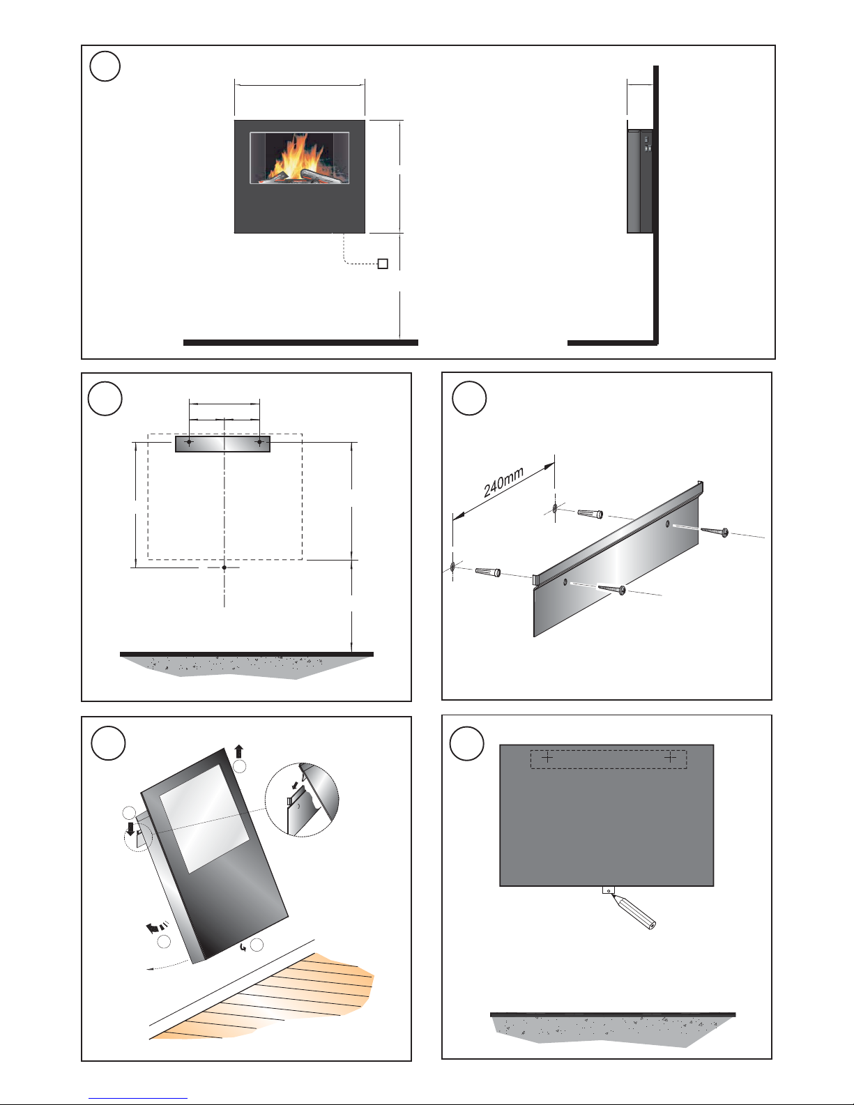
The wall bracket must be fitted horizontally and the cable routed
to the bottom right of the heater as in Fig. 1.
A height of 600mm from bottom of heater to floor is recommended
for optimum viewing of fuel bed (see Fig. 2 for recommended
fixing dimensions).
For optimum viewing mark the top two screw fixing positions on
wall in accordance with the recommended fixing dimensions see Fig. 2.
Fix the wall bracket using the two plugs and screws provided see Fig. 3.
Carefully lift the heater up ensuring that the top rear ledge of
heater engages the wall bracket and is sitting centrally positioned
- see Fig. 4 (b).
Rotate the bottom fixing bracket down - see Fig 4. (c).
Gently bring the heater level with the wall - see Fig 4. (d).
Mark the bottom hole position (see Fig. 5), remove the heater
ensuring that the bottom fixing bracket is rotated up.
Drill and fit wall plug.
Refit the heater to the wall fixing bracket (i.e. follow steps as in
Fig. 4 a, b, c and d above) and rotate the bottom fixing bracket
down again and use the screw provided to permanently fix the
heater in place.
The heater should not be connected until the instruction leaflet
is read fully.
Note: Fix the appliance to the wall using the screws and wall
plugs provided, but these fixings do not suit all types of walls.
IT IS IMPORTANT THAT THE FIXING DEVICE CHOSEN IS
APPROPRIATE TO THE WALL MATERIAL TO WHICH THE FIRE
IS BEING FIXED. SOME MODERN INTERNAL BUILDING
MATERIALS ARE VERY LOW DENSITY BLOCK AND REQUIRE
SPECIALIZED FIXING DEVICES TO PROVIDE A SAFE,SECURE
INSTALLATION.
Manual & Remote Operation
Setting Operation Setting
Flame Effect Bottom Neon
Flame Effect & 1Kw Heat Press the ‘ I ’ button Middle Neon
Flame Effect & 2Kw Heat Press the ‘ I ’ button again T op Neon
Page 5
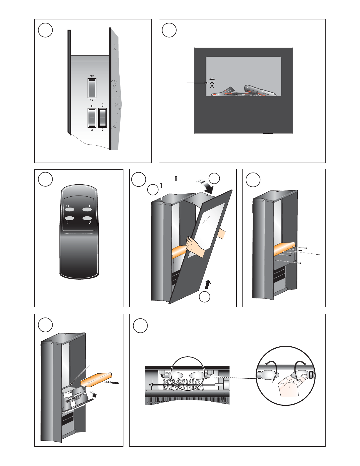
The switches are located at the right hand side of the heater.
The Standby switch must first be turned ‘ON’ to operate the heater
manually or by remote control.
Note: It takes some time for the receiver to respond to the
transmitter. DO NOT PRESS the buttons more than once within
two seconds for correct operation.
To go to the previous settings press the button.
Pressing the
button on the remote turns off the light & heat
settings. To resume press the
button until the desired setting
is reached - see Fig. 8.
To increase or decrease the brightness of the flames, use the
dimmer button or the
button on the Remote Control. The heat
setting will remain the same.
To turn off the power the Standby Switch must be turned ‘OFF’.
Lamp Replacement
WARNING – ALWAYS DISCONNECT FROM THE POWER
SUPPLY BEFORE REMOVING LAMPS.
Warning - The lamps reach high temperatures during operation.
For this reason, allow the lamps to cool down after switching off
the appliance.
The front panel will need to be removed in order to change
lamps.
Warning - Take care handling the front panel as it can be easily
damaged.
a. Remove the two screws which hold the front panel in place
- see Fig. 9.
b. While holding the front by its sides with both hands carefully
tilt forwards - see Fig. 9.
c. Then lift up and out - see Fig. 9
Place the front panel flat on a protective surface such as a matt
with the glass facing away from the floor.
Remove the (4) screws securing the lamp cover plate - see
Fig. 10. Lift the cover plate up and out to remove.
Remove the (2) screws securing the hinged cover - see Fig.
10. Tilt the hinged cover (see ‘b’ in Fig. 11).
Remove the defective lamp by unscrewing it as shown in Fig.
12.
Replace with a 60W E14 SES Clear Candle bulb. Take care not
to over-tighten the lamp.
Steps for reassembling the heater
Refit the hinged cover with fixing screws.
Refit lamp cover plate ensuring that the bend to the rear on the
lamp cover plate slots in between the fuel effect retaining bracket
and the rear glass - see ‘x’ in Fig. 11.
Refit the front panel ensuring that its base is held in place i.e.
that it slots into the channel on the frame, reversing the steps
as outlined previously.
Thermal Safety Cut-out
For your safety, this appliance has been fitted with thermal cutout. In the event that the product overheats, the cut-out switches
the heat off automatically.
To bring the heat back into operation, remove the cause of the
overheating, then unplug or turn off the electrical supply to the
heater for up to 10 minutes.
When the heater has cooled sufficiently, re-connect and switch
on the heater.
Caution: In order to avoid a hazard due to inadvertent resetting
of the thermal cut-out, this appliance must not be supplied
through an external switching device, such as a timer, or
connected to a circuit that is regularly switched on and off by
the utility.
Cleaning
WARNING – ALWAYS DISCONNECT FROM THE POWER
SUPPLY BEFORE CLEANING THE HEATER.
For general cleaning use a soft clean duster – never use
abrasive cleaners. The glass viewing screen should be
cleaned carefully with a soft cloth. DO NOT use proprietary
glass cleaners.
Recycling
For electrical products sold within the
European Community.
At the end of the electrical products useful
life it should not be disposed of with
household waste. Please recycle where
facilities exist. Check with your Local
Authority or retailer for recycling advice in
your country.
Page 6

.
Page 7
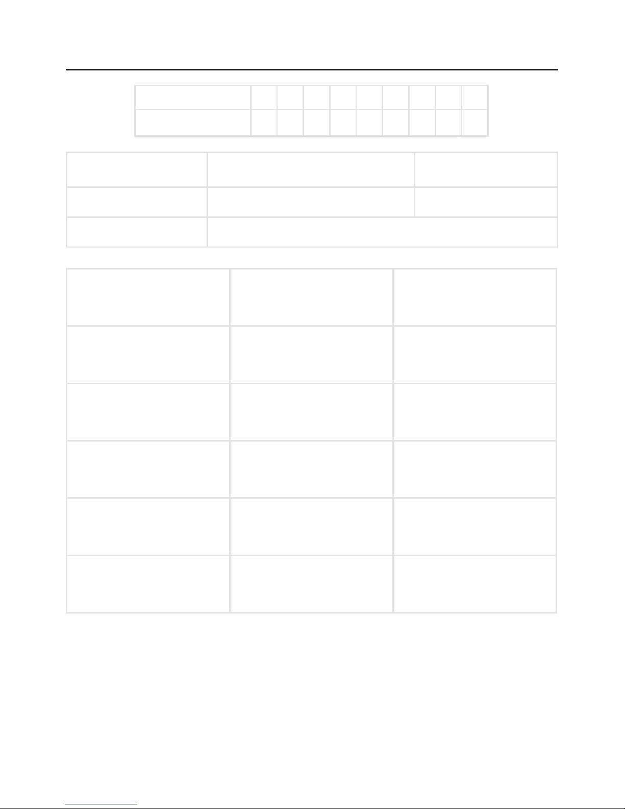
Service Record
Date of purchase Installer stamp / Printed name Date of installation
Place of purchase:
Date Part(s) replaced Engineers Stamp/
Printed Name
Model Number
Serial Number
Should you need to contact us, please call our Customer Care Centre on:
0871 22 22 502.
Calls will be answered in strict rotation, as soon as possible.
Please record your model and serial number in the spaces above.
Having these numbers to hand will help us to help you quickly and more efficiently should
you need to call us for any reason.
Page 8

Stoney Lane, Prescot, Merseyside L35 2XW
Tel: Customer Care 0871 222 2502
Trade Support 0871 222 2625
Customer Support Line 0871 222 2635
Fax: 0871 222 2645
Stoves is a member of Glen Dimplex Home Appliances
www.stoves.co.uk
S7 - E700FIRE
01.2009
700mm Electric Fire
 Loading...