

Page 1

Q900GRF DO
Double Rotostar Oven & Grill
For Natural Gas & LP Gas Models
User, Installation & Servicing Instructions
21258 10 - Q900GRF DO 11/07/2002 10:08 Page 1
Page 2

21258 10 - Q900GRF DO 11/07/2002 10:08 Page 2
Page 3
1
User’s Section . . . . . . . . . . . . . . . . . . . . . . . . . . . . . . . . . . . 2 - 15
Introduction . . . . . . . . . . . . . . . . . . . . . . . . . . . . . . . . . . . . . . . . . . . . . . . 2
Be Safe - Not Sorry. . . . . . . . . . . . . . . . . . . . . . . . . . . . . . . . . . . . . . . . . . 5
Using the Maxigrill . . . . . . . . . . . . . . . . . . . . . . . . . . . . . . . . . . . . . . . . . . 6
Using the Top Oven . . . . . . . . . . . . . . . . . . . . . . . . . . . . . . . . . . . . . . . . . 7
Using the Main Oven . . . . . . . . . . . . . . . . . . . . . . . . . . . . . . . . . . . . . . . . 8
Programmer / Clock. . . . . . . . . . . . . . . . . . . . . . . . . . . . . . . . . . . . . . . . . 9
Cleaning . . . . . . . . . . . . . . . . . . . . . . . . . . . . . . . . . . . . . . . . . . . . . . . . 13
Micro-computer Operation . . . . . . . . . . . . . . . . . . . . . . . . . . . . . . . . . . . . 15
Installation Instructions . . . . . . . . . . . . . . . . . . . . . . . . . . . . 16 - 22
Servicing Instructions . . . . . . . . . . . . . . . . . . . . . . . . . . . . . 23 - 30
Technical Data . . . . . . . . . . . . . . . . . . . . . . . . . . . . . . . . . . . . . 31
Stoves Customer Care . . . . . . . . . . . . . . . . . . . . . . . . . . . . . . . . 32
Please keep this handbook for future reference, or for anyone else
who may use the appliance.
If you smell gas:
- Do not try to light any appliance.
- Do not touch any electrical switch.
- Call the Gas Emergency Helpline at TRANSCO on:
0800 111999
CONTENTS
21258 10 - Q900GRF DO 11/07/2002 10:08 Page 3
Page 4

Thank you for choosing a
British built appliance by Stoves
We hope the following information
will help you to familiarise yourself
with the features of the appliance, and
to use it successfully and safely.
Our policy is one of constant
development and improvement. Strict
accuracy of illustrations and specifications
is not guaranteed. Modification to
design and materials may be necessary
subsequent to publication.
This appliance must be installed in
accordance with the regulations in
force, and only in a well ventilated
space. Read the instructions before
using or installing this appliance.
The Q900GRF DO is designed to fit
into a standard 600mm wide housing
unit with a minimum internal height of
880mm.
The User’s Section in this handbook
covers the operation of the ovens and
grill, but to help you make the most of
your Stoves Q900GRF DO, we have
produced the accompanying Cooking
Guide, which gives more details of its
features and benefits.
Your first year guarantee
To fulfil the conditions of your guarantee,
this appliance must be correctly
installed and operated, in accordance
with these instructions, and only be
used for normal domestic purposes.
Please note that the guarantee, and
Service availability, only apply to the
UK and Republic of Ireland.
Before using the appliance for
the first time, remove any protective
polythene film and wash the oven
shelves and furniture in hot soapy water
to remove their protective covering of
oil. Even so, when you first switch on
the oven or grill, you may notice a
smell or some smoke.
To replace an oven light bulb
Switch off the electricity supply to the
appliance at the socket, to avoid the
risk of electric shock.
Wait until the oven is cool then remove
the oven shelves.
The lens cover on the light can be
removed by grasping the lens cover
and pulling away from the side of the
oven. Unscrew the bulb.
Please note that the oven light bulbs
are not covered by guarantee.
Replacement bulbs can be bought
from most hardware stores.
2
INTRODUCTION
21258 10 - Q900GRF DO 11/07/2002 10:08 Page 4
Page 5

Gas & Electrical connection
Please refer to installation instructions
for the Gas & Electrical Safety Regulations
and the Ventilation Requirements.
In your own interest, and that of safety,
it is the law that all gas appliances be
installed by competent persons, who
will ensure that the installation is in
accordance with “The Gas Safety
(Installation & Use) Regulations 1994”,
& the “The Gas Safety (Installation &
Use) (Amendment) Regulations 1996”.
Failure to comply with these
Regulations is a criminal offence.
Corgi registered installers undertake to
work to satisfactory standards.
Disconnection of gas and electric
appliances should always be carried
out by competent persons.
Warning: This appliance must be
earthed.
In the event of a power cut
1. Switch off the electricity to the
appliance at the socket.
2. When the power returns, see the
‘Programmer / Clock’ section to
‘Set the time of day’.
Condensation
When hot and cold air meet,
condensation forms. The outer door is
air cooled and the inner door gets hot,
so some condensation might form; this
is normal and will disappear within
10 - 15 minutes.
During operation, a metallic click may
be heard occasionally. This is caused
by the gas valve operating and is
quite normal.
Ventilation
The use of a gas cooking appliance
results in the production of heat and
moisture in the room in which it is
installed. Ensure that the kitchen is well
ventilated; keep natural ventilation holes
open or install a mechanical ventilation
device (mechanical extractor hood).
Prolonged intensive use of the
appliance may call for additional
ventilation, for example opening of a
window, or more effective ventilation,
for example increasing the level of
mechanical ventilation where present.
This appliance is not connected to a
products evacuation device.
It should be installed and connected in
accordance with current installation
regulations. Particular attention should
be given to the relevant requirements
regarding ventilation.
3
INTRODUCTION
21258 10 - Q900GRF DO 11/07/2002 10:08 Page 5
Page 6

Glass door panels
To meet the relevant Standards of
Domestic cooking appliances, all the
glass panels on this appliance are
toughened to meet the fragmentation
requirements of BS3193. This ensures
that, in the unlikely event that a panel
breaks, it does so into small fragments
to minimise the risk of injury.
Please take care when handling, using
or cleaning all glass panels as any
damage to the surfaces or edges may
result in the glass breaking without
warning or apparent cause at a later
date. Should any glass panel be
damaged, Stoves strongly recommend
that it is replaced immediately.
Ready lights
The ready lights are located in the
control knob windows, below the
indicator dial.
When the appliance is switched on,
the red lights will come on.
A steady green light indicates when
the selected oven or grill has reached
a suitable temperature.
If the lights are flashing, refer to
“Micro-computer Operation” section.
The Gas Consumer Council (GCC) is
an independent organisation which
protects the interests of gas users. If
you need advice, you will find the
telephone number is your local
telephone directory under Gas.
Cooling fan
When you switch on the ovens or grill
you will hear the cooling fan start.
This fan provides air for the burners
and keeps the exterior of the
appliance cool during cooking, the
appliance will not operate unless the
fan is operating.
If the fan malfunctions the appliance
will require servicing. The fan may
continue to operate to cool the
appliance for a few minutes after the
last control has been switched off.
Environmental Protection
Stoves Limited is committed to protecting
the environment and operates an
Environmental Management System
which complies with BS EN ISO
14001:1996.
Disposal of packaging
• All our packaging materials are
recyclable and environmentally
friendly.
• Please help us to protect our
environment by disposing of all
packaging in an environmentally
friendly manner.
• Please contact your local authority
for the nearest recycling centre.
Caution: Packaging materials can
pose a risk of suffocation - keep away
from children.
4
INTRODUCTION
21258 10 - Q900GRF DO 11/07/2002 10:08 Page 6
Page 7

When you are cooking, keep
children away from the vicinity
of the appliance.
This product is designed as a domestic
cooking appliance for the preparation
and cooking of domestic food
products, and should not be used for
any other purpose.
• Remove all packaging, protective
films and oils from the appliance
before using for the first time.
• Make sure you read and understand the instructions before using
the appliance.
• Keep electrical leads short so they
do not drape over the appliance
or the edge of the worktop.
• Keep all flammable materials (such
as curtains, furnishings & clothing)
away from the appliance.
• Parts of the appliance may be hot
during or immediately after use.
Allow sufficient time for the appliance to cool after switching off.
• Never use the appliance for
heating a room.
• Do not drape tea towels over the flue
vents as this creates a fire hazard.
• When opening the appliance
door, take care to avoid skin
contact with any steam which may
escape from the cooking.
• Do not use aluminium foil to cover
the grill pan, or put items wrapped
in foil under the grill as this creates
a fire hazard.
• Do not use foil on oven shelves, or
allow it to block the oven flue, as
this creates a fire hazard, and
prevents heat circulation.
• Drop-down doors: Do not place
items on the door when open.
• Do not use the oven with the door
inner glass panel removed.
• Use oven gloves when removing
hot food / dishes from the oven or
grill. The oven / grill and utensils
will be very hot when in use.
• When cooking heavy items, eg;
turkeys, do not pull the oven shelf
out with the item still on the shelf.
• Switch off the electricity supply
before replacing the oven light bulb,
to avoid the risk of electric shock.
Warning: This appliance must be
earthed.
All installation, servicing and
maintenance work should be carried
out by a competent person who will
comply with current Regulations,
Standards and Requirements.
When you have finished
cooking check that all controls
are in the off position.
As with all gas appliances, it is
recommended that your appliance is
serviced regularly.
5
BE SAFE - NOT SORRY
21258 10 - Q900GRF DO 11/07/2002 10:08 Page 7
Page 8
Caution: Accessible parts may
be hot when the grill is used.
Young children should be kept
away.
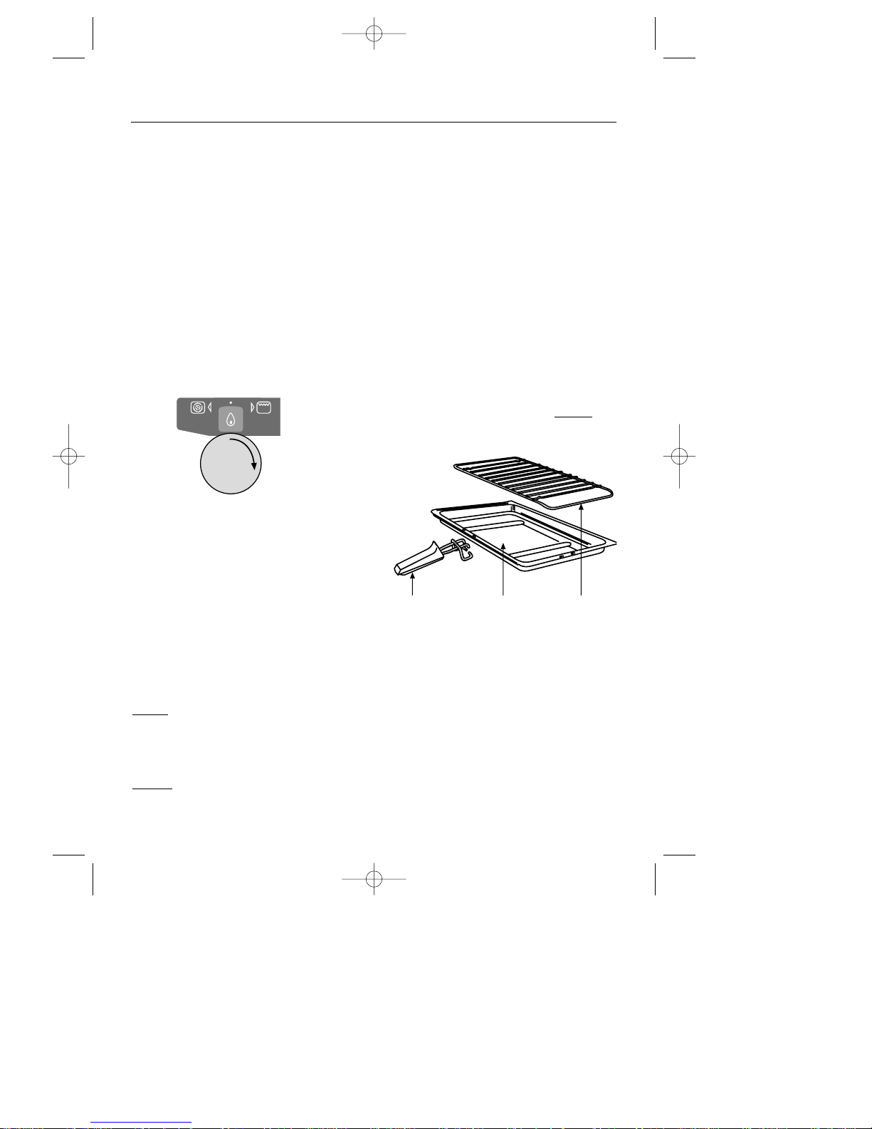
Grill ignition
Open the grill door. Turn the Top
Oven / Maxigrill control knob clock-
wise to the grill setting.
The grill door must be fully open when
the grill is used. If the door is closed
the grill burner will go out. The grill
will re-light when the door is opened
again.
There is a short delay before ignition
whilst the cooling fan speeds up - this
may be for several seconds.
To switch off, return the control knob to
the “off” position.
Note that the grill will not function
when the appliance is set for
automatic cooking.
Caution:
Never
cover the grill pan or trivet
with cooking foil or allow fat to build
up in the grill pan, as this creates a
fire hazard.
Do not
use the grill if the grill burner
glass is cracked.
Preheating
For best cooked results, the grill should
be preheated until the green ready
light appears (about 3 minutes).
Detachable grill pan handle
Place the handle over the edge of
the grill pan. The handle should be
removed from the pan during grilling,
to prevent overheating.
The handle is designed for removing /
inserting the grill pan under the grill
when grilling.
If cleaning the grill pan when it is hot,
use oven gloves to move it. Do not
use
the handle to pour hot fats from the
The grill trivet
Food for grilling should be placed
within the area defined by the kinks in
the trivet wires.
To suit the type of food, the grill trivet,
which is in the grill pan, can be
inverted to give a high or low position,
or it may be removed completely.
6
handle grill pan trivet
USING THE MAXIGRILL
21258 10 - Q900GRF DO 11/07/2002 10:08 Page 8
Page 9
When you are cooking keep
children away from the vicinity
of the oven.
The top oven can be used generally,
in the same way as the main oven,
to cook the full range of dishes, but it
is a
SECONDARY oven and there are
some differences.
Please refer to the accompanying
‘Cooking Guide’ for cooking in the
top oven.
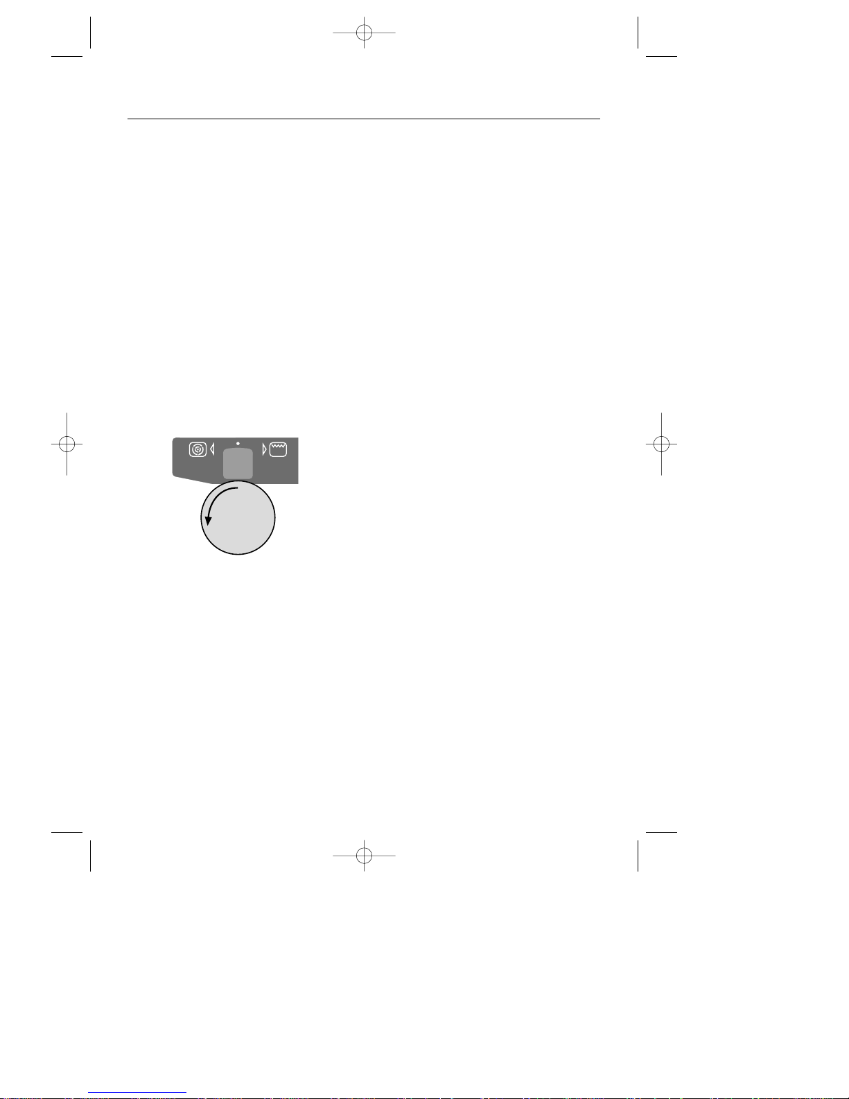
Top oven ignition
Turn the Top Oven / Maxigrill control
knob anticlockwise to the required
gas mark.
There is a short delay before ignition
(up to 10 seconds) as the cooling fan
builds up pressure.
The top oven burner will not come on
unless the oven door is closed.
To turn off, return the control knob to
the “off” position.
Oven shelves
The oven shelf must be positioned with
the upstand at the rear of the oven and
facing upwards.
Position baking trays and roasting tins
on the middle of the shelves, and leave
one clear shelf position between
shelves, to allow for circulation of heat.
Baking tray and roasting tins
For best cooked results and even
browning, the maximum size baking
trays and roasting tins that should be
used are as follows;
Baking tray 350mm x 280mm
This size of baking tray will hold up to
20 small cakes.
Roasting tin 370mm x 320mm
We recommend that you use good
quality cookware. Poor quality trays
and tins may warp when heated,
leading to uneven baking results.
Note:
As part of the cooking process, hot air
is expelled through a vent at the top of
the oven(s). When opening the oven
door, care should be taken to avoid
any possible contact with potentially hot
air, since this may cause discomfort to
people with sensitive skin. We recommend
that you hold the underneath of the
oven door handle.
7
9
USING THE TOP OVEN
21258 10 - Q900GRF DO 11/07/2002 10:08 Page 9
Page 10
When you are cooking keep
children away from the vicinity
of the oven.
Manual operation
The oven cannot be used manually
when the programmer is set for
automatic cooking; if A (AUTO) is
showing on the programmer display,
press the cook time and ready
time buttons simultaneously to cancel
the automatic setting.
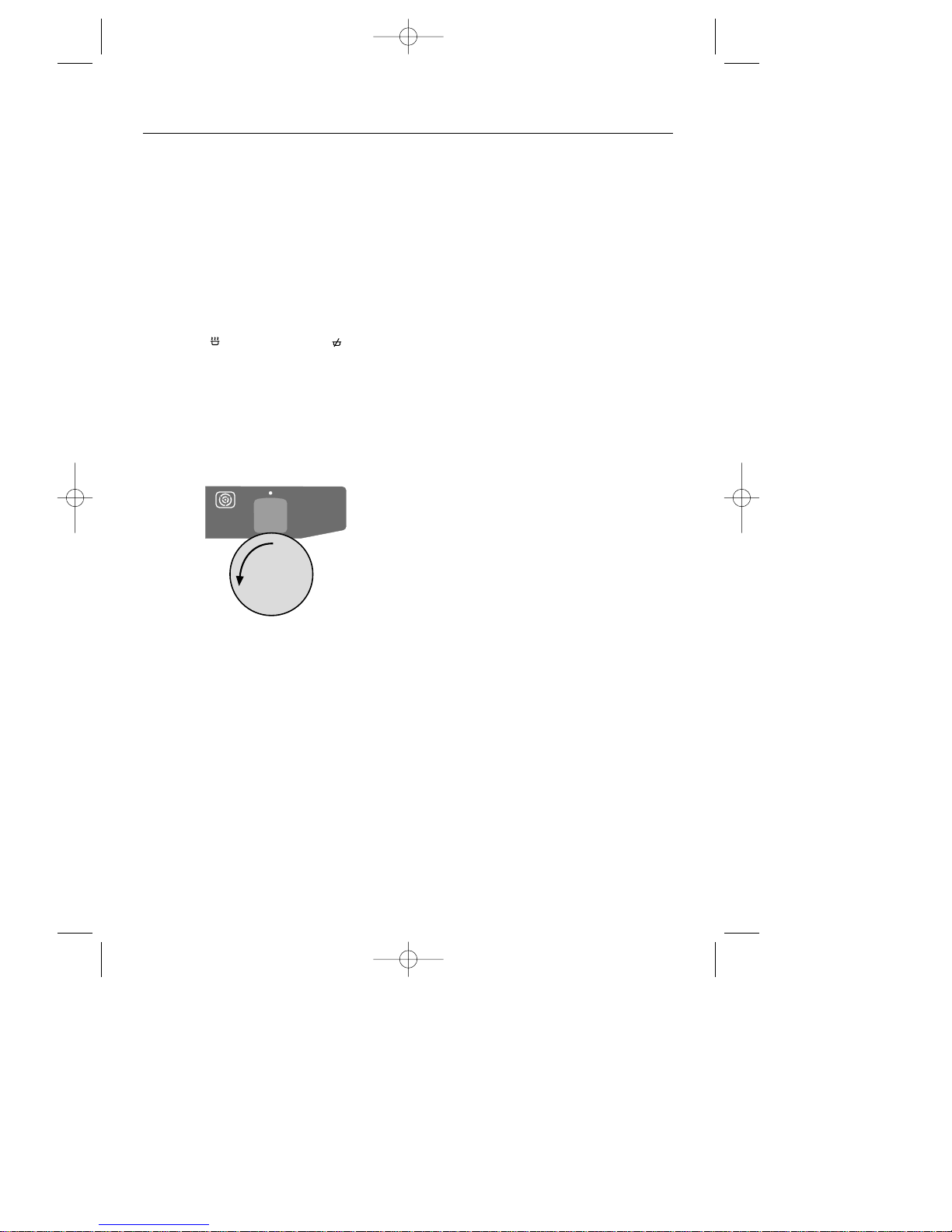
Main oven ignition
Turn the control knob anticlockwise to
the required gas mark.
To turn off, return the control knob to
the “off” position.
Automatic operation
See ‘Programmer / Clock’ section.
Please refer to Cooking Guide for
important instructions for automatic
cooking.
We recommend that 15 minutes is
added to the cooking time when using
the automatic cooking facility, to allow
for preheating.
Oven light
All oven lamps will light when an oven
is in use.
Baking tray and roasting tins
For best cooked results and even
browning, the maximum size baking
trays and roasting tins that should be
used are as follows;
Baking tray 350mm x 280mm
This size of baking tray will hold up to
20 small cakes.
Roasting tin 370mm x 320mm
We recommend that you use good
quality cookware. Poor quality trays
and tins may warp when heated,
leading to uneven baking results.
Oven shelves
The oven shelf must be positioned with
the upstand at the rear of the oven and
facing upwards.
Position baking trays and roasting tins
on the middle of the shelves, and leave
one clear shelf position between
shelves, to allow for circulation of heat.
Note:
As part of the cooking process, hot air
is expelled through a vent at the top of
the oven(s). When opening the oven
door, care should be taken to avoid
any possible contact with potentially hot
air, since this may cause discomfort to
people with sensitive skin. We recommend
that you hold the underneath of the
oven door handle.
8
9
USING THE MAIN OVEN
21258 10 - Q900GRF DO 11/07/2002 10:08 Page 10
Page 11
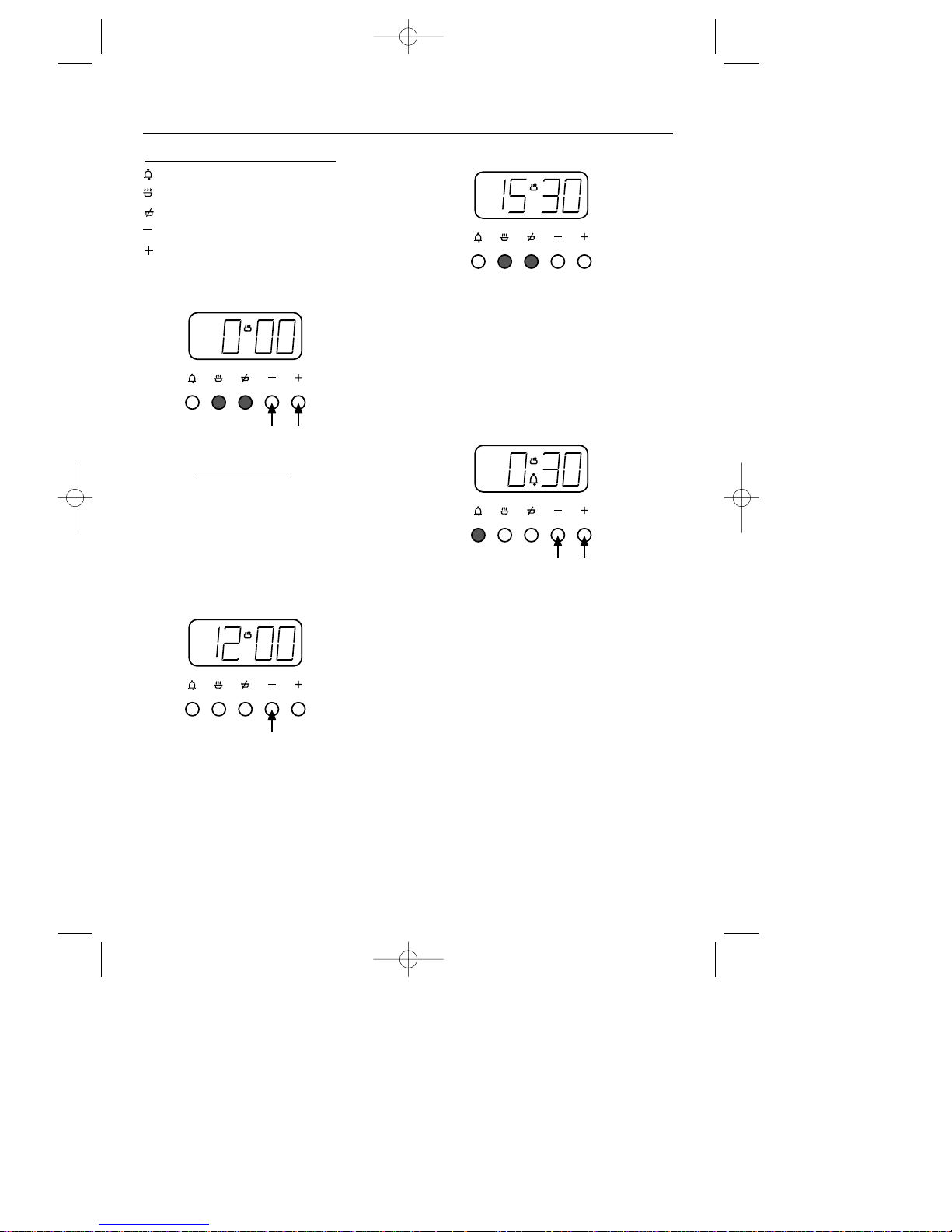
The Programmer Buttons
minute minder
cook time
ready time
minus
plus
To set the “Time of Day”
Press the cook time and ready time
buttons simultaneously
, and keep the
buttons depressed. Use the plus and
minus buttons to set the time of day,
eg; 12.00.
A (Auto) symbol goes out, cookpot
symbol comes on.
To select an alarm tone
Press the minus button to listen to the
first tone.
Release the minus button and press it
again to listen to the second tone, etc.
Releasing the minus button after the
tone has sounded will automatically
select that tone.
Manual operation
To set the programmer to manual
operation at any time (cancelling any
automatic setting), press the cook time and
ready time buttons simultaneously. The
programmer must be set to manual before
the appliance can be used manually.
Setting the minute minder
Press the minute minder button, then
use the plus and minus buttons to set
the required time.
The minute minder (bell) symbol will
appear on the display.
You can cancel the minute minder at
any time by pressing the minute
minder button and the minus button
until the display returns to 0.00.
After setting, the display will revert to
show the time of day, but you can press
the minute minder button, and the
display will show the minutes remaining.
The tone will sound at the end of the
time set - to cancel the tone, press the
minute minder button.
9
PROGRAMMER / CLOCK
21258 10 - Q900GRF DO 11/07/2002 10:08 Page 11
Page 12
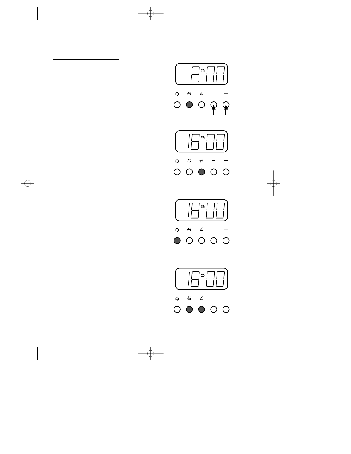
10
1. A (Auto) symbol appears.
2.
3. A (Auto) symbol will flash.
4. A (Auto) symbol goes out.
Semi-automatic cooking
(example)
You have started cooking a meal or
dish in the oven, and want to set the
time for the oven to switch off
.
Press the cook time button, then use the
plus and minus buttons to set the
display to show the length of cooking
time required, eg; 2 hours as shown (1).
After setting, the display will revert to
show the time of day, but you can
press the cook time button and the
display will show how much cooking
time still remains on the clock.
Press the ready time button, and the
display will show the actual time the
oven is going to switch off, eg; 18.00
as shown (2).
At the end of the cooking time, the
alarm will sound, and the oven will
automatically switch off.
To switch off the alarm, press the
minute minder button (3).
When the oven has switched off,
return the oven control knob to
the “off” position, and press the
cook time and ready time buttons to
return to manual operation (4).
If you wish to cancel the automatic
setting, or to cancel any remaining
cooking time left on the clock before
the alarm sounds, press the cook time
and ready time buttons simultaneously.
(4).
A
U
T
O
A
U
T
O
A
U
T
O
PROGRAMMER / CLOCK
21258 10 - Q900GRF DO 11/07/2002 10:08 Page 12
Page 13
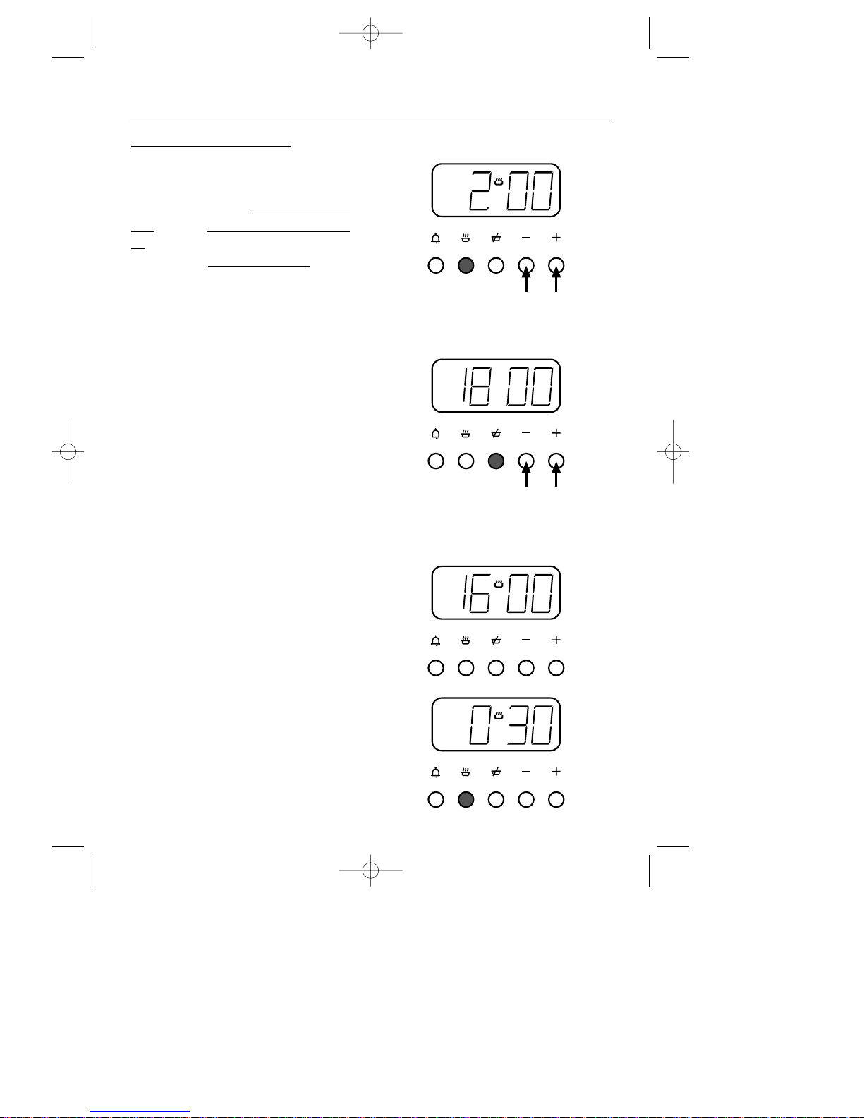
11
5. A (Auto) symbol appears.
6. The cookpot symbol will
disappear from display.
7. The cookpot symbol will appear
on display.
8.
Fully automatic cooking
(example)
For use when a delayed start time is
required.
You want to set the length of cooking
time, and the time for the oven to switch
off. The programmer will automatically
calculate the cooking start time.
Press the cook time button, then use the
plus and minus buttons to set the
display to show the length of cooking
time required, eg; 2 hours as shown (5).
Press the ready time button, and the
present ready time will be displayed.
Using the plus and minus buttons you
can set the display to show the actual
time you want the oven to switch off,
eg; 18.00 hours (6.00 pm) (6).
The display will revert to show time of day.
After setting the programmer,
turn the oven control to the
required temperature.
The oven will automatically switch on
at the calculated start time of 16.00
hours (4.00 pm) (7).
A single press of the cook time button
shows the cooking time remaining
before the oven automatically switches
off (8).
A
U
T
O
A
U
T
O
A
U
T
O
A
U
T
O
PROGRAMMER / CLOCK
21258 10 - Q900GRF DO 11/07/2002 10:08 Page 13
Page 14
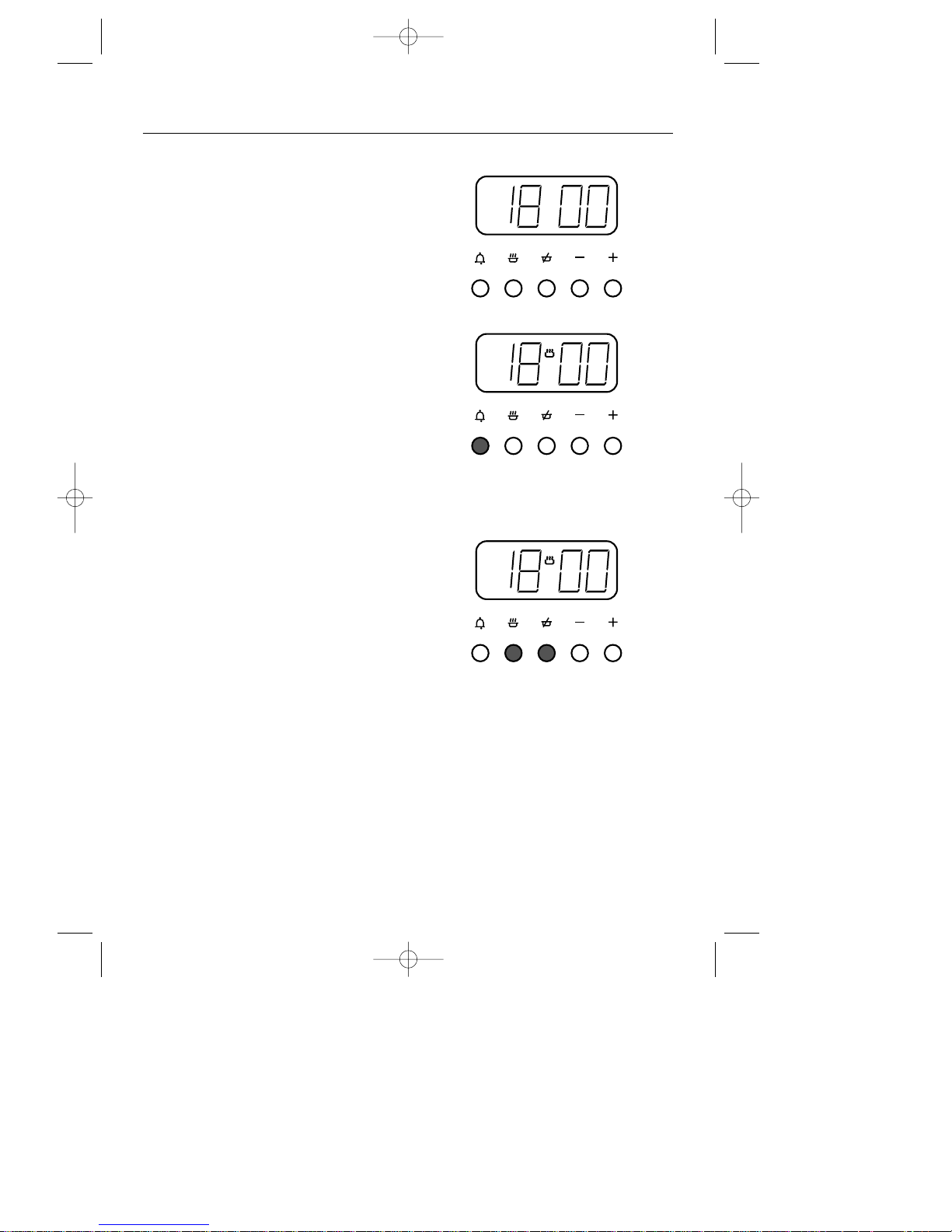
12
9. A (Auto) symbol will flash.
10.
11. A (Auto) symbol goes out.
The oven will automatically switch off
at 18.00 hours (6.00 pm) and the
alarm will sound (9).
To switch off the alarm press the
minute minder button (10).
When the oven has switched off,
return the oven control knob to the
“off” position, and press the cook time
and ready time buttons simultaneously
(11).
If you wish to cancel the automatic
setting before cooking has started,
and return to manual operation, press
the cook time and ready time buttons
simultaneously (11).
To cancel any remaining cooking time
left on the clock before the alarm
sounds, press the cook time and ready
time buttons simultaneously (11).
A
U
T
O
A
U
T
O
PROGRAMMER / CLOCK
21258 10 - Q900GRF DO 11/07/2002 10:08 Page 14
Page 15
Caution: Any cleaning agent
used incorrectly may damage
the appliance.
Always let the oven cool before
cleaning.
Some cooking operations generate a
considerable amount of grease. This,
combined with spillage, can become a
hazard if allowed to accumulate on
the appliance through lack of cleaning.
In extreme cases this may amount to
misuse of the appliance and could
invalidate your guarantee.
It is recommended that the appliance
is cleaned after open roasting.
Do not use caustic pastes, abrasive
cleaning powders, coarse wire wool
or any hard implements, as they will
damage the surfaces.
All parts of the appliance can be
safely cleaned with a cloth wrung out
in hot soapy water.
Chrome plated parts
OVEN SHELVES & OVEN SHELF RUNNERS,
GRILL PAN TRIVET
Do not use abrasives or polishes. Use a
moist soap pad - eg; “Brillo”. These items
may also be cleaned in a dishwasher.
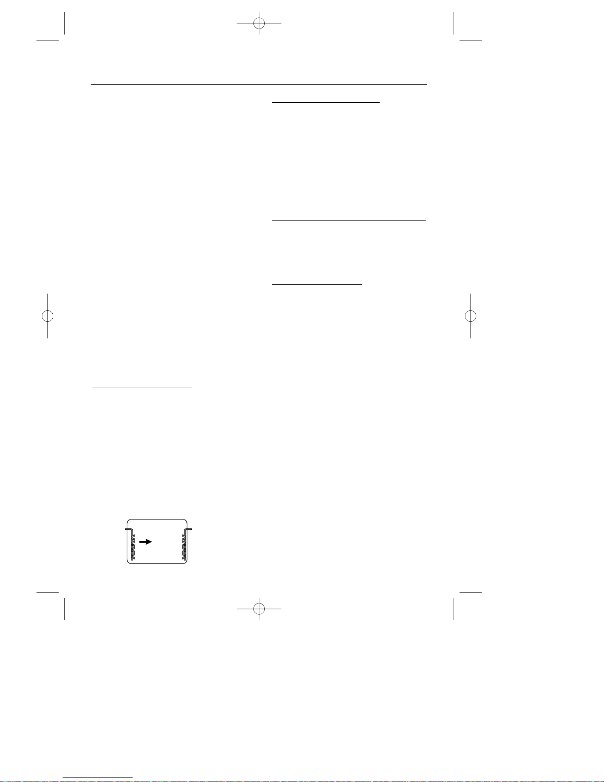
Note: Oven shelf runners can be
removed for cleaning. Grasp the
runners, and slide out of the hanging
holes as shown.
Vitreous enamel parts
GRILL PAN, OVEN FLOOR
Use a mild cream cleaner - eg; “Cif”.
Stubborn marks may be removed with
a moistened “Brillo” pad.
The grill pan may be cleaned in a
dishwasher, or with a nylon brush in
hot soapy water.
Painted, plastic & metal finish parts
DOOR HANDLE, CONTROL KNOBS
Only use a clean cloth wrung out in
hot soapy water.
Easy care surfaces
OVEN SIDES AND BACK
We recommend that the appliance is
cleaned after open roasting, and also
after roasting at temperatures higher
than gas mark 5, to help prevent a
build up of fats. Use of a trivet in a
roasting tin when roasting will help
reduce fat splashing.
Caution: Most types of cleaning
agent will damage these surfaces.
Only use a few drops of washing up
liquid in hot water. Wipe the surfaces
with a clean cloth wrung out in hot soapy
water - if larger splashes of fat do not
readily disappear, scrub the area with
a nylon brush or nylon pan scourer
and hot soapy water. Rinse well and
heat the oven to dry the surfaces.
13
CLEANING
21258 10 - Q900GRF DO 11/07/2002 10:08 Page 15
Page 16
Glass parts
FACIA PANEL, OUTER & INNER DOOR GLASS
PANELS
Use a mild cream cleaner - eg; “Cif”.
Rinse thoroughly and dry with a soft
cloth.
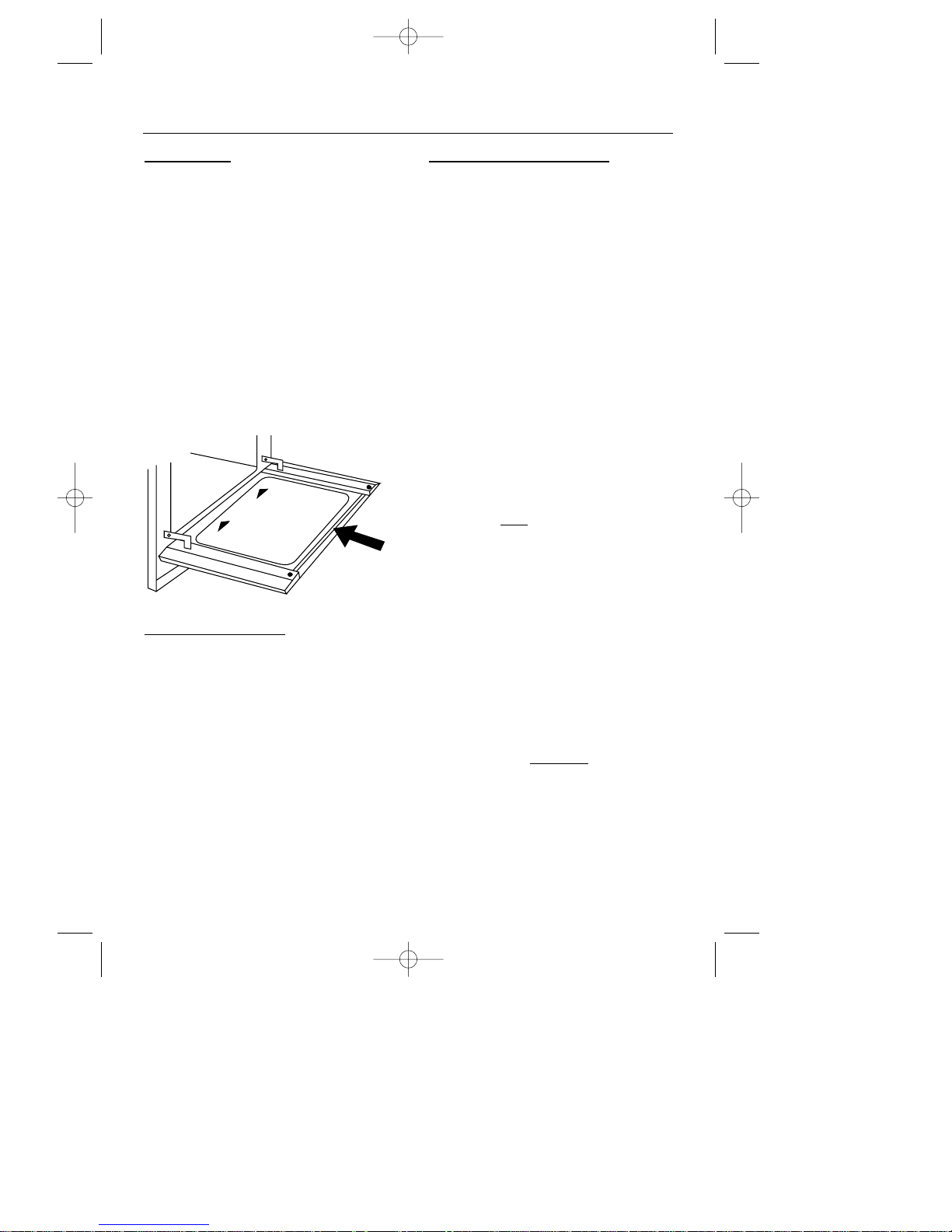
Important: the inner door glass
panel can be removed for cleaning but
it must be replaced the right way up as
shown (so the reflective side faces
inwards), and pushed fully in to the
stop position. To remove the glass
panel, open the door wide, hold the
top and bottom edges and slide out.
Ceramic grill glass
After using the oven or grill, wait until
the grill glass is cool before giving it a
quick wipe over.
Most splashes on the grill glass will
burn off as the grill is used, but if
necessary, it can be cleaned using a
ceramic hob cleaner or a moist soap
pad. When cleaning, do not exert
excessive pressure on the grill glass.
For removing stubborn deposits, we
recommend a ceramic hob scraper.
Stainless Steel surfaces
(stainless
steel finish models only)
FACIA PANEL, HANDLES, DOOR PANELS
Only use a clean cloth wrung out in hot
soapy water, and dry with a soft cloth.
Stubborn marks can be removed using
“Luneta”. We recommend that you
clean the whole of the stainless steel
area to maintain a uniform finish.
Supplies can be purchased from
H.R.P.C. - contact direct sales order line
✆ 01772 819 672.
Do not use undiluted bleach or any
products containing chlorides as they
can permanently damage the steel.
Extra care should be taken when cooking
food in salted water. Some foods are
corrosive - eg; vinegar, fruit juices and
especially salt
- they can mark or
damage stainless steel if they are left
on the surface. Turn off and wipe any
spillage immediately, taking care to
avoid skin contact with any hot surface
or spillage.
Sharp objects can mark the surface of
stainless steel, but marks will become
less noticeable with time.
To maintain the finish of the stainless
steel, or to remove any greasy marks,
wipe the stainless steel surface sparingly with a minimum
amount of
“Johnson’s Baby Oil” and kitchen paper.
Do not use cooking oils, as these may
contain salt, which can damage the
stainless steel surface.
14
SLIDE
IN
SLIDE
IN
THIS SIDE UP
CLEANING
21258 10 - Q900GRF DO 11/07/2002 10:08 Page 16
Page 17
The Q900GRF DO double oven & grill unit
uses a built in micro-computer to control the
oven temperature. The computer also
indicates when the ovens are ready for
use, and oversees the gas supply, fan
operation and ignition sequence ensuring
that these are operating safely.
Should the micro-computer find any fault in
the systems under its control, it will either;
- stop the ignition and gas valve
operation or;
- if the cooker is already in use it will
shut down the operation until the fault
is rectified.
The cooling fan will, however, continue to
run on for a while, and the oven lights
remain on.
Electrical interference either from the mains
or other electrical equipment may cause
the micro-computer to indicate a fault when
non exists, chiefly when first turning on.
It may be necessary to reset the microcomputer (by turning the electricity supply
off at the mains plug) when first bringing
the appliance into operation.
Opening oven doors whilst the microcomputer is running through it’s checks
may cause it to lock out.
In the event of a power cut
1. Switch off the appliance at the socket.
2. When the power returns, see the
‘Programmer / Clock section to ‘Set the
time of day’.
In the event of the gas supply being
disconnected it may be necessary to
make several lighting attempts before gas
reaches the appliance.
15
Lamp signal Cause Action
Steady green Selected oven / grill None - normal operation.
has reached required
temperature.
Green lamp & red indicator Soft lockout. Reset - turn control knob off / on.
dial of main oven cavity
flash.
Green lamp & red indicator Hard lockout. Reset - turn off / on at mains. If
dial for both ovens flash (possible interference) recurring, a service visit may be
alternately left / right. required.
Green lamp & red indicator Fault on micro-computer Service visit required.
dial for both ovens flash
together.
MICRO-COMPUTER OPERATION
21258 10 - Q900GRF DO 11/07/2002 10:08 Page 17
Page 18

Before you start: Please read the
instructions. Planning your installation will
save you time and effort.
Prior to installation, ensure that the local
distribution conditions (nature of the gas and
gas pressure) and the adjustment of the
appliance are compatible. The adjustment
conditions are stated on the data badge.
This appliance is not connected to a combustion
evacuation device. It shall be installed and
connected in accordance with current
installation regulation. Particular attention
shall be given to the relevant requirements
regarding ventilation.
In your own interest and that of safety, it is
the law that all gas appliances be installed
and serviced by competent persons.
CORGI registered installers undertake to
work to satisfactory standards.
Where regulations or standards have been
revised since this handbook was printed,
always use the latest edition.
In the UK the regulations and
standards are as follows:
1. Gas Safety Regulations 1996
(Installation and Use).
2. Building Regulations - Issued by the
Department of the Environment.
3. Building Standards (Scotland)
(Consolidated) - Issued by the Scottish
Development Department.
4. The current I.E.E. Wiring Regulations.
5. Electricity at Work Regulations 1989.
6. BS 6172 Installation of Domestic Gas
cooking Appliances
Also, for LP Gas, refer to BS 5482
Part 1, Part 2 or part 3 as relevant.
7. Installation & Servicing Instructions for
this appliance.
For installation in countries other than the
UK, the appliance must be connected in
accordance with all local gas and electrical regulations.
Ventilation Requirements
The room containing the appliance should
have an air supply in accordance with
BS 5440: Part 2: 1989:
• All rooms require an openable window,
or equivalent, and some rooms will
require a permanent vent as well.
• For room volumes up to 5m
3
an air
vent of 100cm2is required.
• If the room has a door that opens
directly to the outside, or the room
exceeds 10m
3
, NO AIR VENT is
required.
• For room volumes between 5m
3
and
10m3an air vent of 50cm2is required.
• If there are other fuel burning appliances
in the same room, BS 5440: Part 2:
1989 should be consulted to determine
the air vent requirements.
• This appliance must not be installed in
a bed sitting room of less than 20m
3
or
in a bathroom or shower room.
Windows and permanent vents should
therefore not be blocked or removed without
first consulting a CORGI gas installer.
LP Gas only - Do not install this appliance
in a room below ground level. This does
not preclude installation into rooms which
are basements with respect to one side of
the building, but open to ground level on
the opposite side.
Failure to install appliances
correctly is dangerous and could
lead to prosecution.
16
INSTALLATION INSTRUCTIONS
21258 10 - Q900GRF DO 11/07/2002 10:08 Page 18
Page 19
Step 1: Prepare installation
Do not lift the appliance by the
door handle.
Remove the fixing screws from the
polythene bag on the top of the
appliance, but leave the appliance in
the base tray packaging until you are
ready to install it.
Whilst every care is taken to eliminate
burrs and raw edges from this appliance,
please take care when handling - we
recommend the use of protective
gloves during installation.
Please note that the weight of this
appliance is approximately 48kg
(unpacked). Take care when lifting it
into the housing unit - always use an
appropriate method of lifting.
Note: When removing the appliance
from the base tray packaging care
should be taken to ensure the appliance
is not damaged.
Siting the appliance
If this appliance is to be installed near
to a corner where the adjacent
cabinets run at right angles forward of
the appliance, there must be a gap of
at least 90mm between the appliance
and the cabinets, to prevent overheating of the cabinets.
When installed in a typical 600mm
deep built in housing unit, the false
back should be removed from the
housing unit, to provide the necessary
depth for installation.
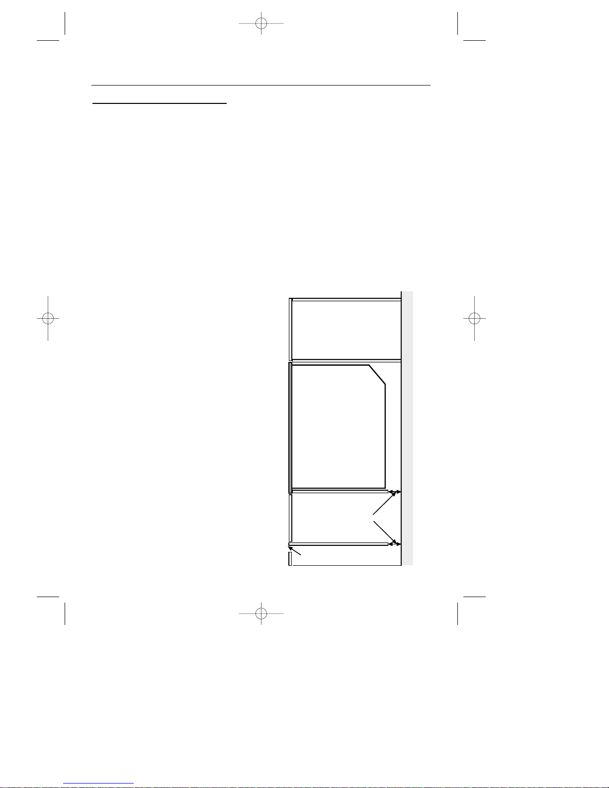
When the false back is removed, it is
normally the case that the support shelf
for the appliance leaves a gap
between the back edge of the support
shelf and the rear wall of approximately 80mm.
If no gap occurs between the back
edge of the shelf and the wall behind
the unit, you must create a gap of at
least 30mm by shortening the shelf
and any other shelf below the appliance.
Cut 12mm from the top of any plinth
that may be fitted (see diagram).
Important: Do not modify the outer
panels of this appliance in any way.
17
Rear wall
12 mm
air gap
30 mm
air gap
INSTALLATION INSTRUCTIONS
21258 10 - Q900GRF DO 11/07/2002 10:08 Page 19
Page 20
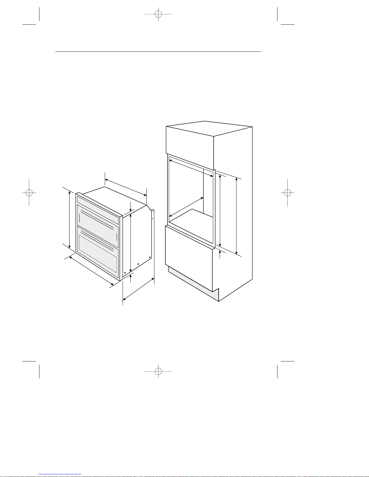
Dimensions
The appliance is designed to fit into a
standard 600mm wide housing unit,
with minimum internal dimensions as
shown.
Note: All sizes are nominal, some
variation is to be expected.
18
min
560 mm
550 mm
min
min
880
mm
869
mm
892
mm
min
888
mm
min
7 mm
547 mm
595 mm
550 mm
17 mm
6 mm
INSTALLATION INSTRUCTIONS
21258 10 - Q900GRF DO 11/07/2002 10:08 Page 20
Page 21
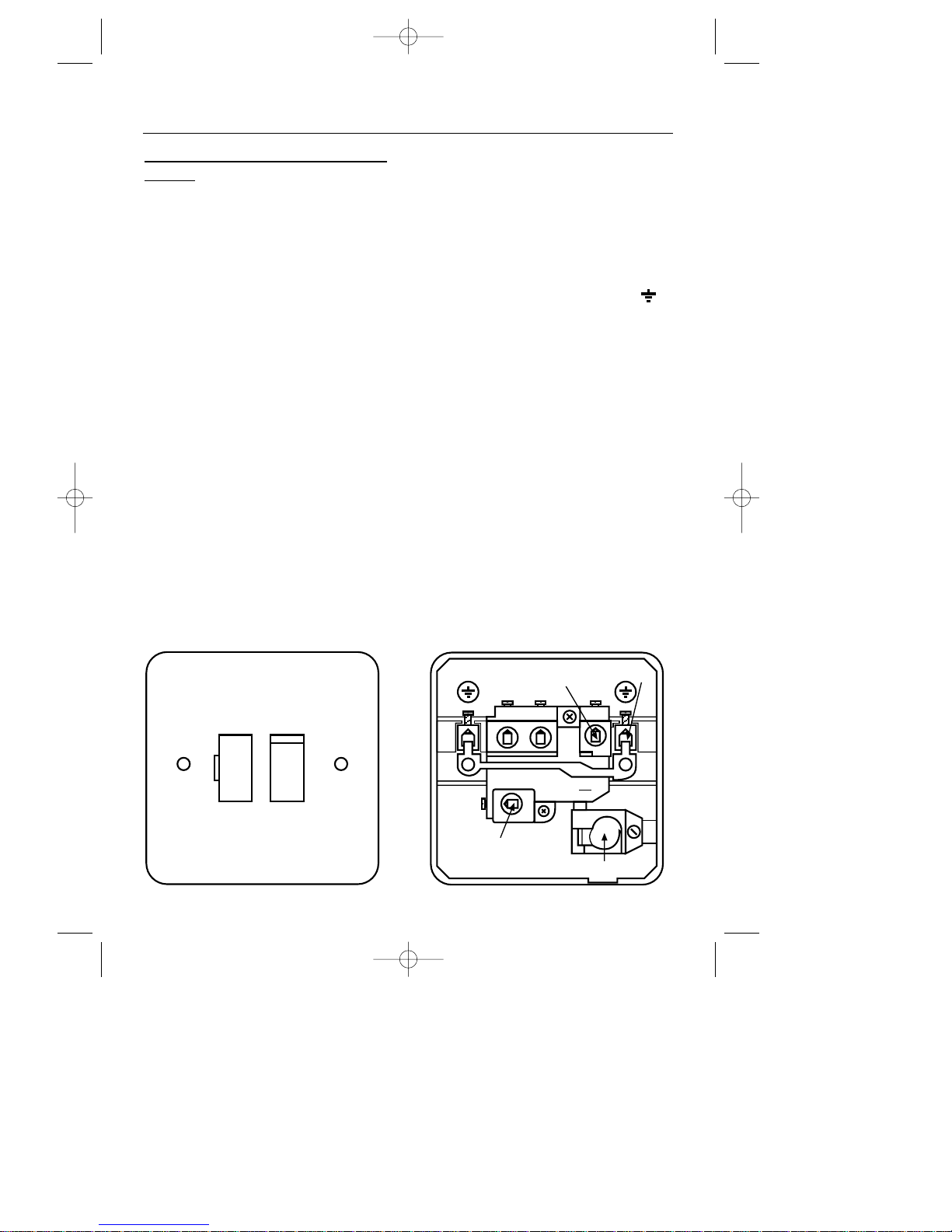
19
Step 3: Connect to the electricity
supply
This appliance must be connected by
a competent person, using fixed
wiring via a double pole switched
fused spur outlet, with a contact
separation of 3mm at all poles.
We recommend that the appliance is
connected by a qualified electrician,
who is a member of the N.I.C.E.I.C.
and who will comply with the I.E.E.
and local regulations.
Warning: This appliance must be
earthed.
The wires in the mains lead are
coloured in accordance with the
following code:
Green & Yellow = earth,
Blue = neutral,
Brown = live.
As the colours of the wires in the mains
lead for the appliance may not
correspond with the coloured markings
identifying the terminals in your spur
box, proceed as follows:
1. The wire which is coloured green
and yellow must be connected to
the terminal marked E (Earth) or
coloured green.
2. The wire which is coloured blue
must be connected to the terminal
marked N (Neutral)
LOAD or
coloured Black.
3. The wire which is coloured brown
must be connected to the terminal
marked L (Live)
LOAD or coloured
Red.
If the supply cord is damaged, obtain
a special cord from the Customer
Support Helpline, which must be fitted
by a qualified person.
ON
FUSE
Use a 3 amp fuse
Typical example of a double
pole fused spur outlet
N
L
SUPPLY
LOAD
L
~
N
LOAD
13
250
Neutral
Live
Earth
Cable
INSTALLATION INSTRUCTIONS
21258 10 - Q900GRF DO 11/07/2002 10:08 Page 21
Page 22
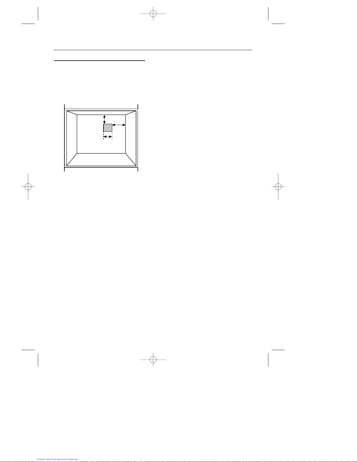
Step 3: Connect to the gas supply
1. The inlet to the appliance is
1
⁄2” BSP
internal situated at the rear top
right corner.
2. Fit the bayonet connection to the
wall in the shaded area as shown.
3. Use a 900mm - 1125mm length of
flexible connector and make sure it
does not block the fan inlet and
cannot come into contact with
moving parts of the cabinetry - eg;
drawers and doors.
4. Natural Gas - Flexible connections should be to BS 669. Parts
of the appliance likely to come
into contact with a flexible connecter have a temperature rise less
than 70˚C.
LP Gas - For flexible connections
use a bayonet type hose, suitable
for use on LP Gas up to 50 mbar
pressure and 70˚C temperature
rise. The flexible hose should be
coloured black with a red stripe,
band or label. If in doubt, contact
your supplier.
5. Rigid connections must be accessible
to disconnect for servicing. Cut a
150mm square hole in the right
hand rear corner of the support
shelf for the supply pipe.
6. Make sure all connections are gas
sound.
Important: - ensure that you route all
mains and electrical cables and
flexible tubing well clear of any
adjacent heat source, such as an oven
grill or hob.
Ensure that all pipe work is of the
correct rating for both size and
temperature.
20
Rear
Wall
60 mm
100
mm
150 mm
square
INSTALLATION INSTRUCTIONS
21258 10 - Q900GRF DO 11/07/2002 10:08 Page 22
Page 23
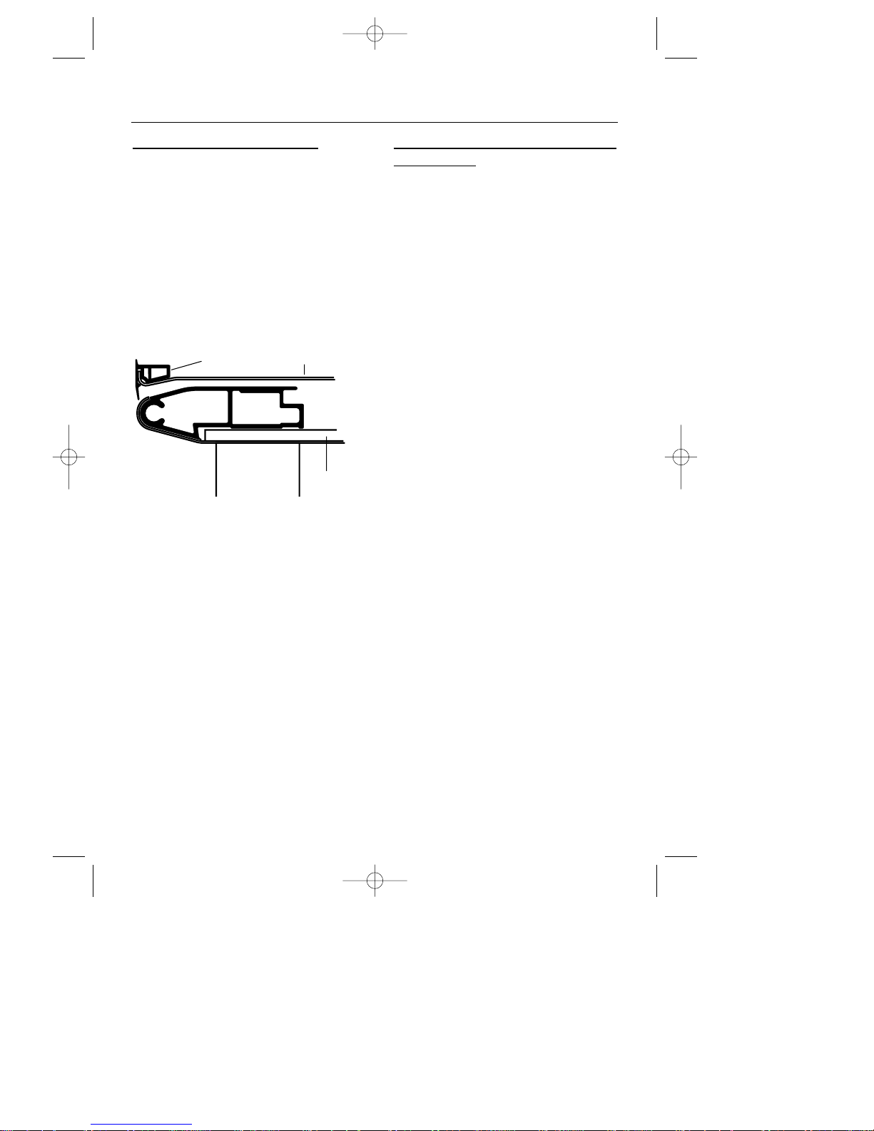
Step 4: Check edging strip
The edging strip is factory fitted to
the front side edges of the appliance
front frame. This strip provides the
cabinetry with extra protection from
any escape of heat.
When installing the product, ensure
that the edging strip is correctly located
on the outer edges of the front frame,
before positioning and securing the
appliance to the cabinet.
When securing the appliance, the
fixing screws provided are driven
through the edging strips into the
cabinet - the seal will straighten up
and sit flush to the cabinet when the
screws are fully home.
Step 5:
Secure appliance into
housing unit
Insert appliance into cabinet. Note:
The unit housing the appliance must be
appropriately fixed.
To secure the appliance to the housing
unit, open the grill / top oven door and
screw 2 screws through the top corner
holes in the front frame, ensuring that the
appliance is centrally located. Take care
not to damage the appliance or cabinet.
21
INSTALLATION INSTRUCTIONS
seal
front frame
door
handle
21258 10 - Q900GRF DO 11/07/2002 10:08 Page 23
Page 24

Step 6: Commissioning
Burner aeration
All burners have fixed aeration and no
adjustment is possible.
Pressure setting
G20 Natural Gas @ 20 mbar
G30 Butane @ 28-30 mbar
G31 Propane @ 37 mbar
The pressure test point is on the top of
the manifold inlet block.
Programmer
The programmer must be set to the
time of day before the main oven
can be used manually - see the
‘Programmer / Clock’ section to ‘Set
the time of day’.
Electrical Systems Check
In the event of an electrical fault, the
preliminary electrical system check
(earth continuity, short circuit, polarity
and resistance to earth) must be
carried out. There is also a Fault Finding
Section in the Servicing Instructions.
Ignition
The automatic ignition continues to
spark for a short time after the burner
flame has lit until the flame is
established.
Grill
1. The door must be open for the grill
burners to ignite.
2. Turn clockwise to the grill setting.
3. Close the door and check that the
burner goes out. The grill burner
will re-ignite when the door is
opened again.
Main Oven
1. The door must be closed for the
oven burner(s) to ignite. The oven
burner will go out when the door is
opened but will re-light when the
door is closed again.
2. Turn the oven control knob to the
required setting.
Top Oven
1. Turn the control knob to the
required setting.
Before leaving the installation
Show the customer how to ignite the
oven and grill and give them this
handbook.
Thank you.
22
INSTALLATION INSTRUCTIONS
21258 10 - Q900GRF DO 11/07/2002 10:08 Page 24
Page 25

23
Before servicing - Disconnect the gas and electrical supplies
After servicing - Check gas soundness
Wiring Diagram . . . . . . . . . . . . . . . . . . . . . . . . . . . . . . . . . . . . . . . . . . . 24
Fault finding . . . . . . . . . . . . . . . . . . . . . . . . . . . . . . . . . . . . . . . . . . 25 - 27
1. Facia glass panel . . . . . . . . . . . . . . . . . . . . . . . . . . . . . . . . . . . . . . 28
2. Remove appliance from housing . . . . . . . . . . . . . . . . . . . . . . . . . . . . . 28
3. Door glass panel(s) . . . . . . . . . . . . . . . . . . . . . . . . . . . . . . . . . . . . . 28
4. Oven light bulb(s) . . . . . . . . . . . . . . . . . . . . . . . . . . . . . . . . . . . . . . 28
5. Top & Rear compartment access . . . . . . . . . . . . . . . . . . . . . . . . . . . . 28
6. Oven igniter electrode . . . . . . . . . . . . . . . . . . . . . . . . . . . . . . . . . . . 28
7. Oven burner fan unit . . . . . . . . . . . . . . . . . . . . . . . . . . . . . . . . . . . . 29
8. Micro-computer . . . . . . . . . . . . . . . . . . . . . . . . . . . . . . . . . . . . . . . . 29
9. Door switch(es) . . . . . . . . . . . . . . . . . . . . . . . . . . . . . . . . . . . . . . . . 29
10. Cooling fan . . . . . . . . . . . . . . . . . . . . . . . . . . . . . . . . . . . . . . . . . . 29
11. Oven light fittings . . . . . . . . . . . . . . . . . . . . . . . . . . . . . . . . . . . . . . 29
12. Grill burner . . . . . . . . . . . . . . . . . . . . . . . . . . . . . . . . . . . . . . . . . . 29
13. Ceramic grill glass . . . . . . . . . . . . . . . . . . . . . . . . . . . . . . . . . . . . . . 29
14. Grill igniter electrode . . . . . . . . . . . . . . . . . . . . . . . . . . . . . . . . . . . . 29
15. Programmer / Clock . . . . . . . . . . . . . . . . . . . . . . . . . . . . . . . . . . . . 30
16. Solenoid block . . . . . . . . . . . . . . . . . . . . . . . . . . . . . . . . . . . . . . . . 30
17. Pressure switch . . . . . . . . . . . . . . . . . . . . . . . . . . . . . . . . . . . . . . . . 30
18. Door seal(s) . . . . . . . . . . . . . . . . . . . . . . . . . . . . . . . . . . . . . . . . . . 30
SERVICING INSTRUCTIONS
21258 10 - Q900GRF DO 11/07/2002 10:08 Page 25
Page 26
24
J11
J8 3 2 5 4 710
J12J16
J9J21
J6
J1
HT
HT
A1
L
N
A2
N
M.O.
T.O. / Gr.
T.O. / Gr.
M.O.
E2
K
K
P
A3
G1
G2
G3
D
D
B
C3C2C1
F2
F1
E1
00
M.O. T.O.Gr.
11
22
22
22
44
66
66
Q
22
00
con
5
con 3con 1
con 4con 2
PIN2PIN
10
PIN
11
PIN
1
PIN5PIN3PIN4PIN
12
F1
22
33
44
66
44
33
22
66
44
C
NO
99
66
11
66
22
9966
9966
66
99
44
22
K
K
9966
6699
66
66
66
11
33
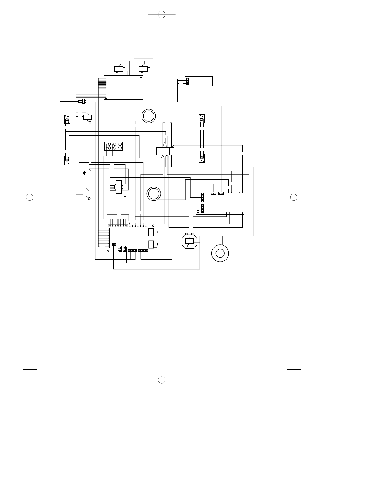
Key: A1 - Main oven fan; A2 - Top oven fan; A3 - Cooling fan; B - Transformer; C1 Solenoids - grill; C2 - Solenoids - main oven; C3 - Solenoids - top oven; D - Earth screw, E1
- Thermistor - main oven; E2 - Thermistor - top oven; F1 - Door switch; F2 - Pressure switch;
G1 - HT - main oven; G2 - HT - grill; G3 - HT - top oven; K - Lamps; N - Programmer;
P - Speed control, Q - 68Ω resistor (LPG 100Ω).
Wiring colour code: 00 - Black; 11 - Brown; 22 - Red; 33 - Orange; 44 - Yellow; 66
- Blue; 99 - White. Note: Earth wires (green) not shown.
WIRING DIAGRAM
21258 10 - Q900GRF DO 11/07/2002 10:08 Page 26
Page 27

Method of operation
When the control knob is rotated from
the ‘OFF’ position, a microswitch
closes and allows the gas control
solenoids to be energised; the same
movement of the control rotates an
electrical potentiometer and lights a
red LED.
The micro-computer on the main
control board uses the resistance set
at the potentiometer to determine the
user’s requirements - ie; oven or grill
and oven temperature asked for.
The oven temperature is sensed by a
thermistor at the rear of the oven - the
computer compares the electrical
resistance of this with that set on the
potentiometer, and controls burner
accordingly.
Other inputs to the micro-computer are
signalled by door switches, the timer /
programmer unit and an air flow
checking pressure switch.
The oven fan, cooling fan, and lamps
are operated at mains voltage, the
solenoid valves, and controls at 25V.
The igniter high voltage coils are
mounted on the main PCB.
Upon applying mains voltage, the
micro-computer makes a series of checks
of the air flow and flame detector
before allowing start up.
Electrical faults
These may be either component failure
or wiring / connector faults. Should
any disconnections be made, it is
important that they be re-connected
exactly as before or the computer will
lock out; poor connections are the most
common fault. It is most important that
earth wires (green) are all connected
and earth screws tight.
There are two forms of microcomputer lockout
Hard lockout (
HLO); for instance, air
flow failure. This is indicated by the
green lamps and red indicator dials of
both ovens flashing alternately left /
right. The cooling fan may continue to
run for a while. Hard lockout can only
be cancelled by turning off the mains
electricity supply.
Soft lockout (
SLO), for instance, reignition failure, will cause the green
lamp and red indicator dial of the
main oven cavity to flash - the cooling
fan may run on, the oven fan will not
run on. To cancel soft lockout, turn off
the control knob.
Should the oven temperature not
reach 40˚C within approximately
four minutes, the micro-computer will
consider that a fault has occurred and
go to lockout.
25
FAULT FINDING
21258 10 - Q900GRF DO 11/07/2002 10:08 Page 27
Page 28
26
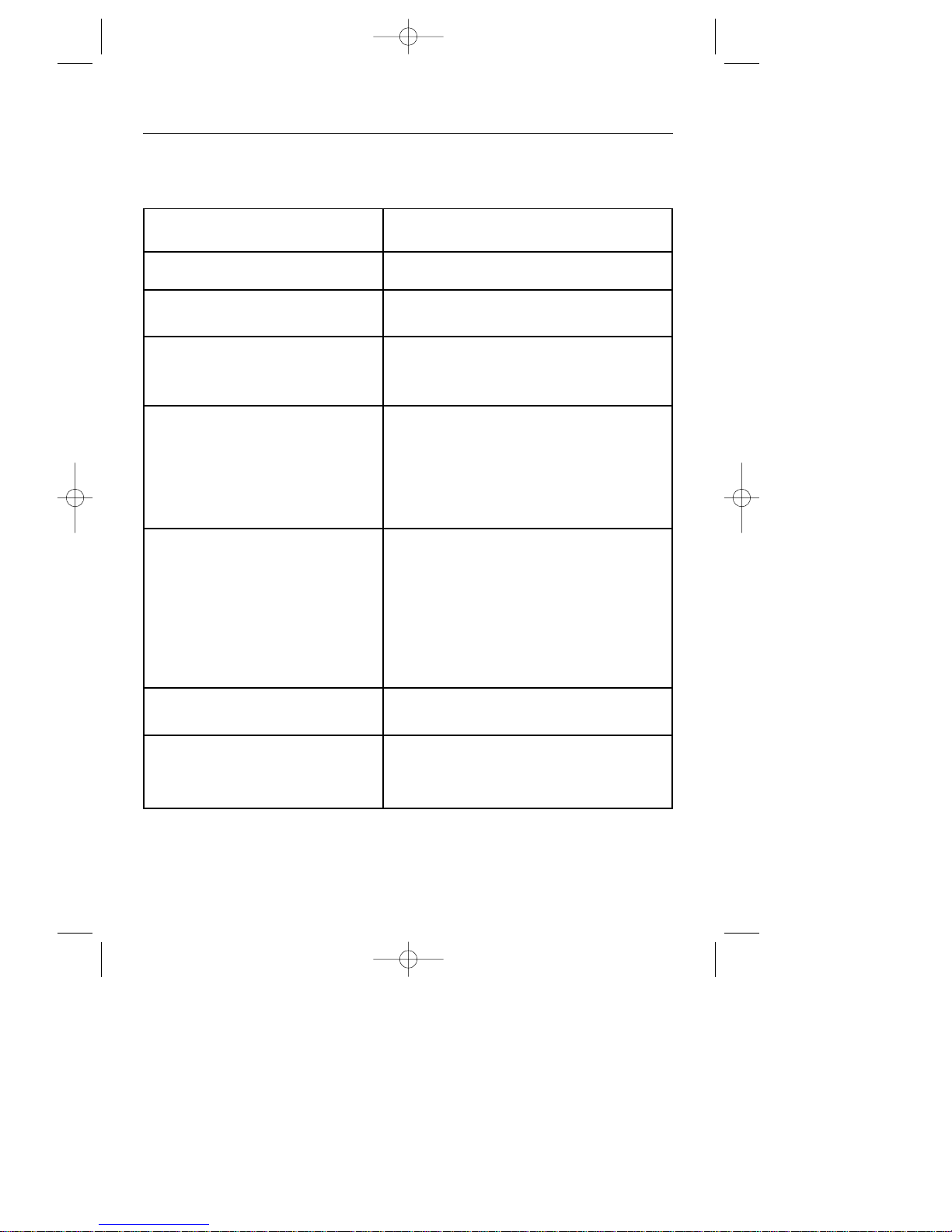
Typical faults assuming all wiring is correct
(ensure programmer is set to manual):
Symptom Fault
HLO on switching On mains Component fault on main PCB, incorrect wiring
HLO on turning On oven/grill Fault on control board / potentiometer,
incorrect wiring, open circuit solenoid.
Oven start up, burner lights and Short circuit thermistor assembly.
immediately goes out, ready light on Note: at room temperature, thermistor
resistance is approximately 100 kΩ.
Oven fails to ignite (check that 1. Incorrectly positioned or open circuit spark
electrode sparks correctly) electrode (note both grill and oven
electrodes must be connected).
2. Faulty solenoid valve.
3. Gas not at appliance.
4. Blocked injector jet.
Oven goes out before set 1. Incorrectly adjusted spark electrode (low
temperature is reached flame current).
2. Low gas pressure.
3. Incorrectly positioned potentiometer or
indicator disc.
4. If oven goes out after approximately 4
mins, this is due to a disconnected or open
circuit thermistor.
Oven fails to re-ignite after set 1. Incorrectly set spark electrode.
temperature is reached 2. Low Gas Pressure.
Oven fan fails to start 1. Open circuit in programmer.
burner does not light 2. Component failure on main board
3. Component failure at control board.
FAULT FINDING
21258 10 - Q900GRF DO 11/07/2002 10:08 Page 28
Page 29
27
Grill faults are generally similar to
those listed for the oven.
If the cooling fan starts and runs, the
electrodes should spark and the
solenoid valves can be heard to open.
If the spark electrodes are correctly
positioned and no spark occurs, there
may be an air detector pressure switch
fault, one faulty solenoid valve or no
gas supply.
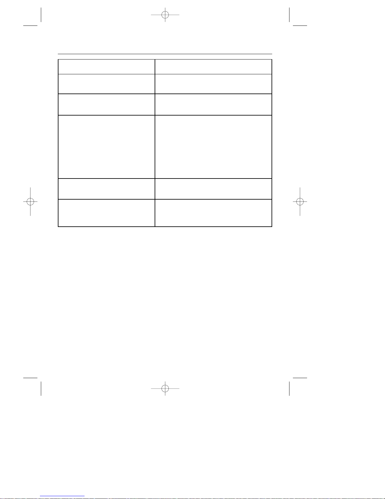
Symptom Fault
Oven fan does not start Faulty fan or connections.
burner lights, oven lamp lights
Oven fan does not start Component failure on main board.
lamps do not light
Cooling fan fails to start 1. Faulty fan.
‘ON’ LED fails to light 2. Faulty programmer.
cooling fan fails to start 3. Faulty component on either board.
4. Faulty mains transformer.
5. Miss set or faulty potentiometer on control
board.
6. Faulty transformer or mains supply.
7. Faulty microswitch on control board.
Temperature exceeds set level Damaged or disconnected thermistor probe.
Oven goes to HLO after four / five minutes.
Appliance will not work, green lamp Faulty micro-computer.
& red indicator dial for both ovens
flash together
FAULT FINDING
21258 10 - Q900GRF DO 11/07/2002 10:08 Page 29
Page 30
Before servicing - disconnect the gas
and electric supplies.
After servicing - Check for gas
soundness.
Note: The control system only allows gas
to flow when the back panel is in place
and fully screwed down. Oven or grill
should only be operated with all panels in
place.
1. Facia glass panel
a. Remove appliance from housing (2).
b. Remove the top cover plate.
c. The glass facia is secured at both ends
by a single screw.
d. Note: The programmer is held on the
rear of the glass facia by high
temperature adhesive tape.
2. Remove appliance from housing
c. Disconnect the electricity supply.
b. When handling the appliance, care
should be taken to ensure the trim is
not damaged.
c. If the appliance is secured into the
housing with screws through the front
frame, open the door and unscrew the
4 corner screws.
d. Grasp the bottom of the frame, pull
forward and out onto a suitable surface.
e. Disconnect the gas supply inlet from
the rear wall.
3. Door glass panel(s)
a. Open the door and insert 2 screws
through the inner holes in the door
hinge arms (to stop the door from
springing up when you remove the
outer glass panel).
b. Slide out the inner glass panel.
c. Remove 2 plastic inner glass stops at
bottom of door extrusion.
d. The door foot can be withdrawn
completely from the door extrusion.
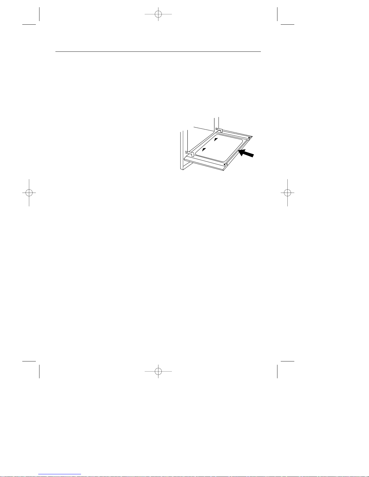
Important: The inner glass panel
must be replaced the right way up as
shown (the reflective side faces
inwards) and also pushed fully into the
stop position.
4. Oven Light bulb(s)
a. Remove the oven shelves.
b. Grasp the back edge of the light cover
and pull forward.
c. Unscrew the bulb.
5. Top and rear compartment
access
a. Remove the appliance from housing
unit (2).
b. Unscrew and remove top plate screws.
c. For rear compartment access, remove
top panel first. Slide rear panel sideways off the inlet valve block feeding
the supply cord through the grommet.
6. Oven igniter electrode
a. Remove the fan cover.
b. Remove 2 screws holding electrode.
c. Pull electrode out.
d. Push back sleeving and disconnect
electrode lead.
28
SLIDE
IN
SLIDE
IN
THIS SIDE UP
SERVICING INSTRUCTIONS
21258 10 - Q900GRF DO 11/07/2002 10:08 Page 30
Page 31

7. Oven burner fan unit
a. It is easier to lift out the fan cover if you
first remove the oven shelf runners:
(i) Pull the bottom edge away from the
oven side.
(ii)Disengage the runners from the
hanging holes.
b. From the inside of the oven, unscrew
the 4 screws which secure the fan
cover to the back of the oven.
c. Remove 2 screws from electrode
bracket.
d. Remove rear service panel (5).
e. Prevent motor from rotating whilst
unscrewing burner from within oven.
Note: Left hand thread, turn clock-
wise to unscrew.
8. Micro-computer
a. Gain access to the rear chamber (5)
and disconnect all wire connectors
from PCB.
b. Remove PCB earthing screws found at
the top RH and bottom LH corners.
c. Ensure the distance tube around the
earthing screws is retained and
replaced when refitting the PCB, as it
will not work without them.
d. The complete board can now be
removed by disconnecting the
insulating stand-offs.
Note: It is practically impossible to
exchange individual components from
the computer board. A complete new
board should be substituted ensuring
correct software is installed.
9. Door switch
a. Remove appliance from housing (2).
b. Remove top panel and RHS panel.
c. Unscrew the screws which secure the
door switch and its bracket to the oven
door frame.
10.Cooling fan
a. Remove appliance from housing (2).
b. Gain access to rear compartment (5).
c. Disconnect the fan leads from the
terminal block.
d. Unscrew the 4 screws which secure
the fan mounting bracket.
e. Remove the 4 screws which secure the
fan to the mounting bracket.
11.Oven light fitting(s)
a. Remove appliance from housing (2).
b. Remove the top and side panels.
c. Remove the leads from the back of the
light fitting.
d. Squeeze in the metal retaining clips to
release the fitting from the oven side.
12.Grill burner
a. Remove appliance from housing (2).
b. Unscrew the top and rear panel
securing screws.
c. Remove the top and rear panels.
d. Detach the spring clip at the injector
block.
e. From the top, remove the grill burner
securing screws & lift out the grill
burner complete with cover.
13.Ceramic grill glass
a. Gain access to top compartment (5).
b. Remove the grill burner (12).
c. Lift up all the tabs which secure the
grill glass.
d. Replace glass and bend tabs down.
14.Grill igniter electrode
a. Remove the grill burner (12).
b. Unclip the electrode wire from the
control board.
Important: The electrode connection
must be to the correct connector at the
control board.
29
SERVICING INSTRUCTIONS
21258 10 - Q900GRF DO 11/07/2002 10:08 Page 31
Page 32
15.Programmer / clock
a. Remove appliance from housing.
b. Remove top panel.
c. Remove facia glass.
d. The clock can now be disconnected
and disengaged by cutting through
the adhesive tape.
16.Solenoid Block
a. Remove appliance from housing.
b. Remove top, rear and right side panels.
c. Disconnect three compression pipe
connections.
d. Disconnect electric socket from the
control board.
e. Remove 4 screws from side of
appliance securing the block.
17.Pressure Switch
a. Remove appliance from housing.
b. Remove top and rear panels.
c. The pressure switch can now be
disconnected and the two securing
screws removed.
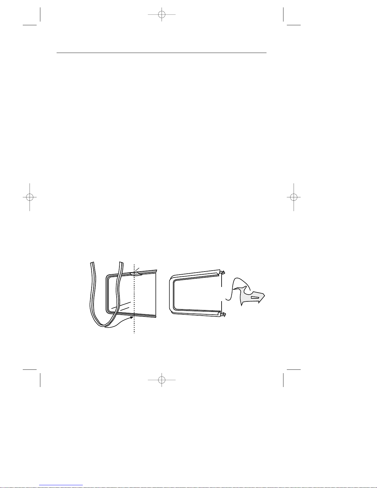
18.Door seal
a. Pull off the old seal.
b. Slacken screws in the stainless steel
flue cover at the front of the oven/grill
roof to ease insertion of the seal.
c. Partly open the door to obtain best
access for the seal all around the
oven/grill.
d. Locate the middle of the new seal and
start to push into place at the middle of
the bottom edge of the oven/grill cavity.
e. Make sure the narrow gap goes to the
inside, and locates onto the oven cavity.
f. Do not stretch the seal.
g. Make sure the seal is fitted correctly as
shown, and cut to fit.
h. Re-tighten the screws in the flue cover.
30
narrow
gap
flue
cover
oven
cavity
SERVICING INSTRUCTIONS
21258 10 - Q900GRF DO 11/07/2002 10:08 Page 32
Page 33
Data Badge
Front Frame
Gas Category
This appliance is for use on either
Natural Gas only or LP Gas only. This
is clearly marked on the data badge.
Natural Gas - I
2H, LP Gas - I3+
Pressure Test Point
Top of inlet block
Pressure Setting
G20 Natural Gas @ 20 mbar
G30 Butane @ 28-30 mbar
G31 Propane @ 37 mbar
Ignition
Automatic Spark
Oven / Grill Light(s)
4 x 25W (2 in each oven)
Electrical supply
230 - 240V ~ 50Hz
Grill
Burner: Surface combustion behind
ceramic glass. Spark Gap: 3 - 4mm.
Top Oven
Burner: Rotary surface combustion.
Main Oven
Burner: Rotary surface combustion.
Appliance class
Class 1, freestanding appliance
Countries of Destination
GB - Great Britain, IE - Ireland
31
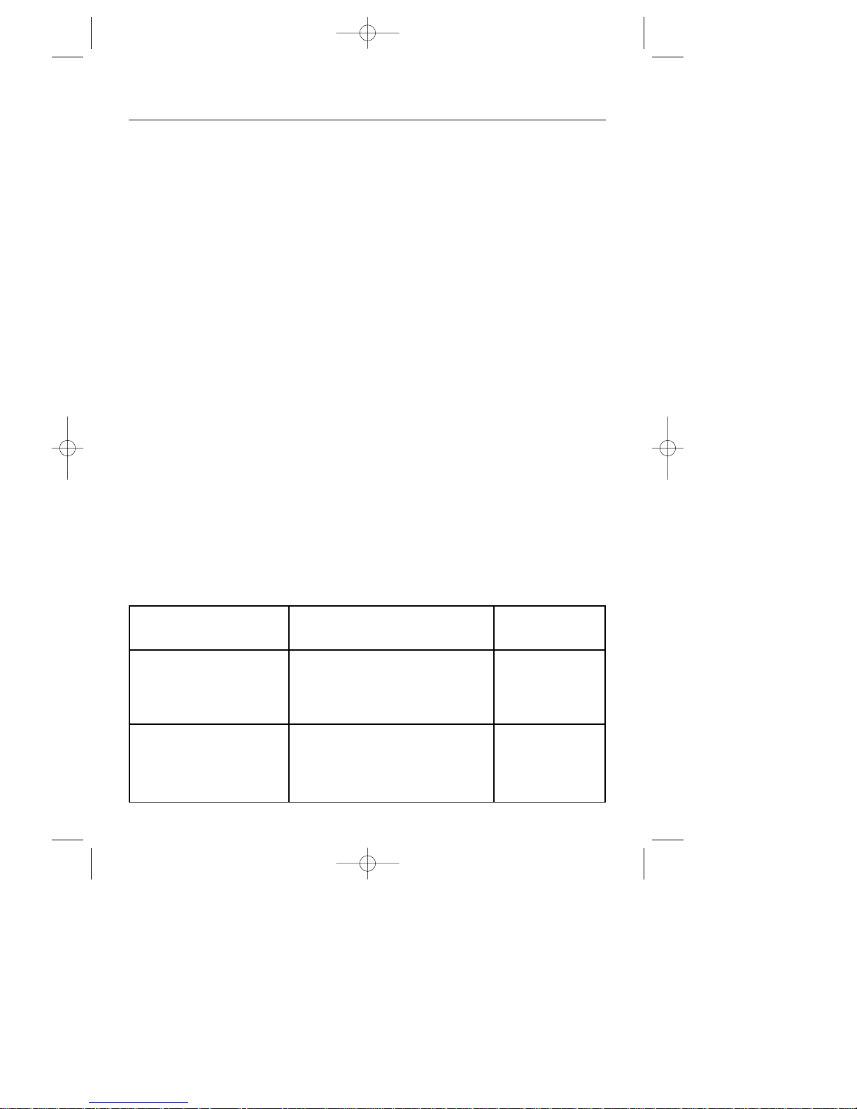
Gas Burner Nominal Grammes per hour Injector
Rate Qn Propane Butane size
Natural Grill 3.2kW - - Amal Size 230
Gas Top Oven 1.85kW - - Amal Size 130
Main Oven 2.5kW - - Amal Size 180
Total heat input ∑Qn 5.7kW - - -
LP Gas Grill 3.2kW 229 g/h 233 g/h Amal Size 95
Top Oven 1.8kW 129 g/h 131 g/h Amal Size 55
Main Oven 2.3kW 164 g/h 167 g/h Amal Size 75
Total heat input ∑Qn 5.5kW 393 g/h 400 g/h -
TECHNICAL DATA
21258 10 - Q900GRF DO 11/07/2002 10:08 Page 33
Page 34
In case of difficulty within the UK and Northern Ireland, please call
STOVES Customer Care Centre Helpline on
0151 432 7838
When you dial this number you will hear a recorded message and be given a
number of options. This indicates that your call has been accepted and is being
held in a queue. Calls are answered in strict rotation as our Customer Care
Representatives become available.
Opening Hours for Customer Care Centre
Monday to Friday 8am - 8pm
Saturday 8.30am - 6pm
Sunday 10am - 4pm
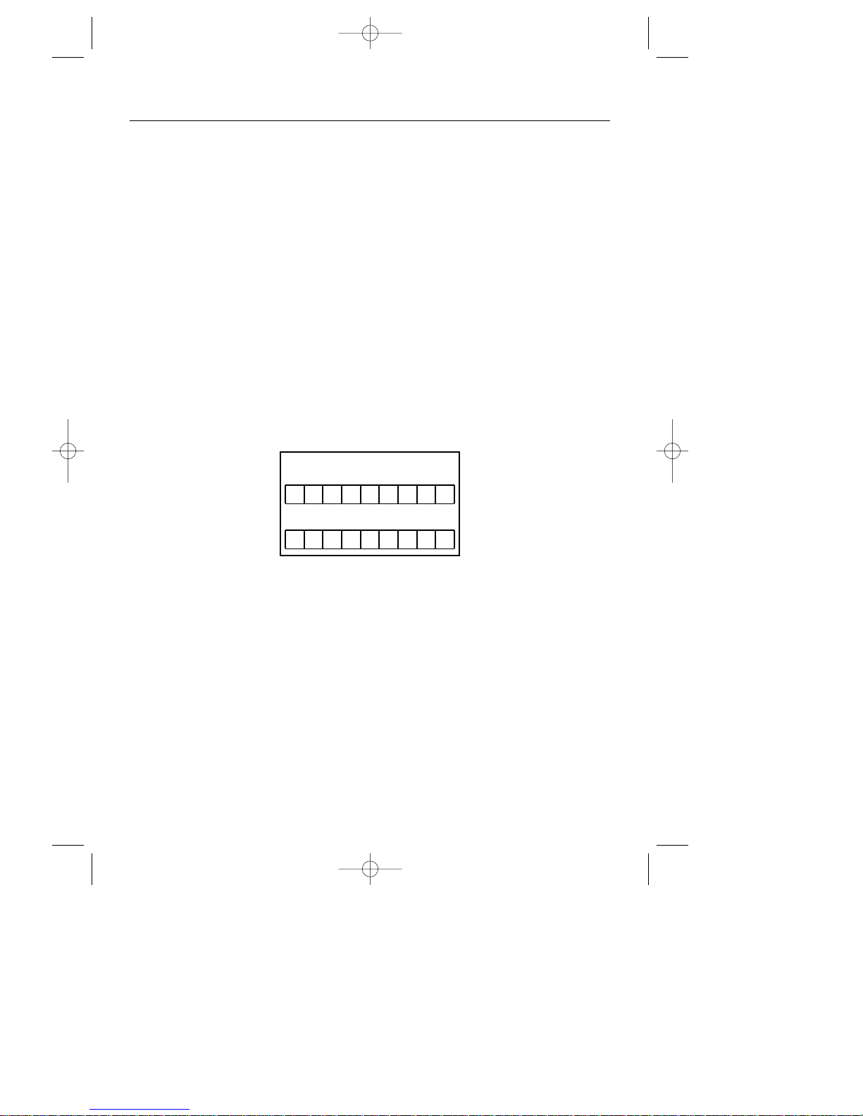
Enter appliance numbers here for future reference:
Please ensure you have the above details (Model No and Serial No) to hand
when calling Stoves Customer Care. They are essential to booking your call.
Outside the UK and Northern Ireland, refer to your local supplier.
STOVES LIMITED, STONEY LANE, PRESCOT, MERSEYSIDE, L35 2XW
Model No
Serial No
32
STOVES CUSTOMER CARE
21258 10 - Q900GRF DO 11/07/2002 10:08 Page 34
Page 35

21258 10 - Q900GRF DO 11/07/2002 10:08 Page 35
Page 36

08 21258 10 © 2002
21258 10 - Q900GRF DO 11/07/2002 10:08 Page 36
 Loading...