

Page 1

STOVES 900GTF
Double Oven & Grill
For Natural Gas Models
& LP Gas Models
Handbook Number 08 18291 01 © 1995, 1996
STOVES 900GTF / 900GTF LP DO & GRILL HANDBOOK No: 08 18291 01
Incase of difficulty please call STOVES Customer Support Helpline on
0151 432 7838
When you dial this number you will hear a ringing tone. This indicates
that your call has been accepted and is being held in a queue.
Calls are answered in strict rotation as our Customer Support
Representatives become available.
Please be ready to supply details of your appliance. We will need to
know the name of the cooker, its colour, serial number and model number; you will find these details on the data badge, which is attached to
the lower front frame, and is visible when you open the oven door.
The Gas consumer Council (GCC) is an independent organisation which
protects the interest of gas users. If you need advice, you will find the telephone number in your local telephone directory under Gas.
18291 01 04/11/2002 12:19 Page 1
Page 2
THANK YOU FOR CHOOSING A BRITISH BUILT APPLIANCE BY STOVES
We hope that the following information will help you to quickly
familiarise yourself with the features of the following appliance, and
use it successfully and safely.
It is the law that all gas appliances be installed and serviced
by competent persons. CORGI registered gas installers
undertake to work to satisfactory standards.
Our policy is one of constant development and improvement. Strict accuracy of
illustrations and specifications is not guaranteed. Modification to design and
materials may be necessary subsequent to publication.
18291 01 04/11/2002 12:19 Page 2
Page 3

User’s Section . . . . . . . . . . . . . . . . . . . . . . . . 2 - 14
Introduction . . . . . . . . . . . . . . . . . . . . . . . . . . . 2
Maxigrill . . . . . . . . . . . . . . . . . . . . . . . . . . . . . 4
Top Oven . . . . . . . . . . . . . . . . . . . . . . . . . . . . 5
Analogue Clock . . . . . . . . . . . . . . . . . . . . . . . . 6
Digital Programmer / Clock . . . . . . . . . . . . . . . . 8
Main Fan Oven . . . . . . . . . . . . . . . . . . . . . . . . 12
Cleaning . . . . . . . . . . . . . . . . . . . . . . . . . . . . . 13
Installation Instructions . . . . . . . . . . . . . . . . . 15 - 20
Servicing Instructions . . . . . . . . . . . . . . . . . . 21- 39
Technical Data . . . . . . . . . . . . . . . . . . . . . . . 40 - 41
CONTENTS
This appliance must be installed in accordance with the regulations in force,
and only in a well ventilated space. Read the instructions before using or
installing this appliance.
PLEASE KEEP THIS HANDBOOK FOR FUTURE SERVICING, OR FOR
ANYONE ELSE WHO MAY USE THE APPLIANCE.
1
18291 01 04/11/2002 12:19 Page 3
Page 4

The 900GTF is designed to fit into a
standard 600 mm wide housing unit
with a minimum internal height of 880
mm.
The
USER’S SECTION in this handbook
covers the operation of the ovens and
grill, but to help you make the most of
your 900GTF, with its main fan oven
and conventional top oven, our Home
Economist has produced the accompanying ‘COOKING GUIDE’ which
gives more details of its features and
benefits.
▲ Your 1st Year Guarantee
To fulfil the conditions of your guarantee, this appliance must be correctly
installed and operated, in accordance
with these instructions, and only be
used for normal domestic purposes.
▲ Gas & Electric Connections
Please refer to the ‘Installation
Instructions’ for the Gas and Electrical
Safety Regulations, and the Ventilation
Requirements.
For your safety, make sure that
installation is carried out by a competent person, who will comply with current Regulations, Standards and
Requirements. CORGI registered gas
installers are approved to work to safe
and satisfactory standards.
Warning: This appliance must
be earthed.
▲ In the event of a power cut
1.Switch off the electricity supply to
the appliance.
2.When the power returns, see the
‘Programmer / Clock’ section to
‘Set the time of day’.
▲ Before using the appliance,
remove any protective polythene film
and wash the oven shelves and furniture in hot soapy water, to remove
their protective covering of oil. Even
so, when you first switch on the oven
or grill, you may notice a smell and
some smoke.
❑ When hot and cold air meet,
condensation forms. The outer door is
cooler than the inner door, so some
condensation might form, this is
normal, and will disappear within 1015 minutes.
INTRODUCTION
2
18291 01 04/11/2002 12:19 Page 4
Page 5
Ventilation
The use of a gas cooking appliance
results in the production of heat and
moisture in the room in which it is
installed. Ensure that the kitchen is
well ventilated; keep natural
ventilation holes open or install a
mechanical ventilation device
(mechanical extractor hood).
Prolonged intensive use of the
appliance may call for additional
ventilation, for example opening of a
window, or more effective ventilation,
for example increasing the level of
mechanical ventilation where present.
▲ Cooling fan
When you switch on the
oven or grill you will hear
the cooling fan start. This
fan keeps the exterior of
the appliance cool during cooking,
and depending upon use, may continue to run for up to 15 minutes after the
control has been switched off. If a
safety related fault occurs, the fan will
continue to run until the appliance
electrical supply is turned off.
❑ Should any fault develop in the
cooling fan, the appliance will need to
be serviced.
INTRODUCTION
3
18291 01 04/11/2002 12:19 Page 5
Page 6
Be Safe
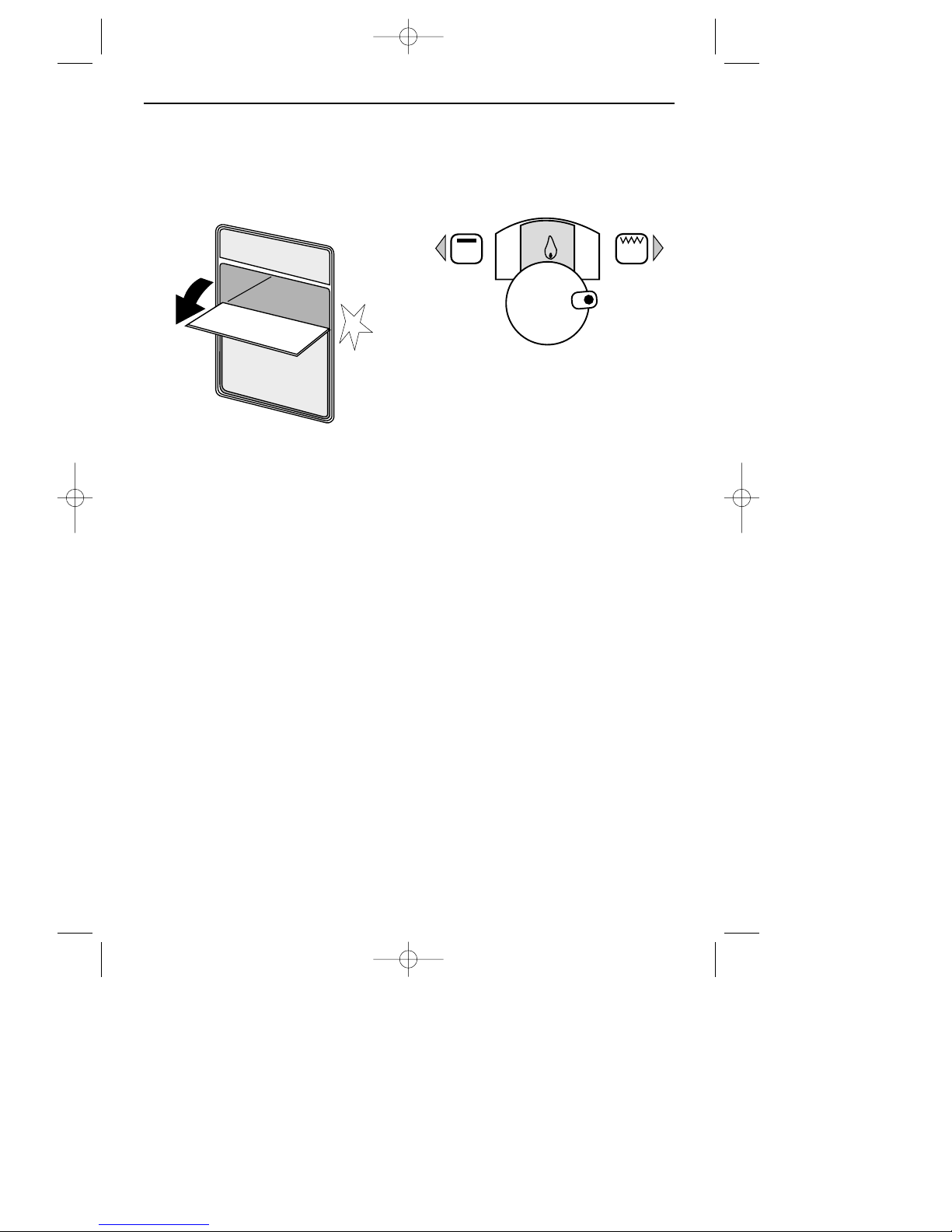
The door must be
OPEN when the grill
is used. If the door is closed the grill
burner will go out. The grill will relight when the door is opened again.
C
AUTION: ACCESSIBLE PARTS MAY BE HOT
WHEN THE GRILL IS USED
, YOUNG CHILDREN
SHOULD BE KEPT AWAY
.
✘ N
EVER cover the grill pan or grid
with cooking foil or allow fat to
build up in the grill pan, as this creates a fire hazard.
✘ D
O NOT use the grill if the grill glass
is cracked.
To turn on the grill
O
PEN the grill door, push in and turn
the grill control knob clockwise to the
grill setting.
There is a short delay before ignition
(up to 10 seconds) and the automatic
ignition will continue to spark for a
short time after the burner has lit until
the flame is established.
Note
The 2 kinks in the oven shelf wires are
there to position the grill pan under the
centre of the grill.
Detachable handle(s)
Place the handle (shield uppermost)
over the edge of the grill pan at the
recess, and slide along to position
CENTRALLY between the two locators. If
you prefer to use two handles, another
handle can be bought from your
supplier. When using two handles,
position between the outer locators.
MAXI GRILL
4
18291 01 04/11/2002 12:19 Page 6
Page 7
❏ The top oven is NOT controlled by
the programmer, and can therefore
be used even when the main oven is
programmed for automatic cooking.
❏ The top oven can be used generally,
in the same way as the main oven,
to cook the full range of dishes, but
it is a
SECONDARY oven and there are
some differences. Please refer to
the accompanying ‘
COOKING GUIDE’
for cooking in the top oven.
The top oven shelf, with its deflector, helps to ensure even baking in the
to oven. It is a different size to the
main oven, and is not intended for
use in the main fanned oven.
Oven light
Press the light button on the facia
panel.
To replace an oven light bulb
Please refer to the ‘main oven’ section.
❏ If it is found, over a period of time,
that the oven becomes hotter when
used at a particular temperature,
then the thermostat may need to be
replaced.
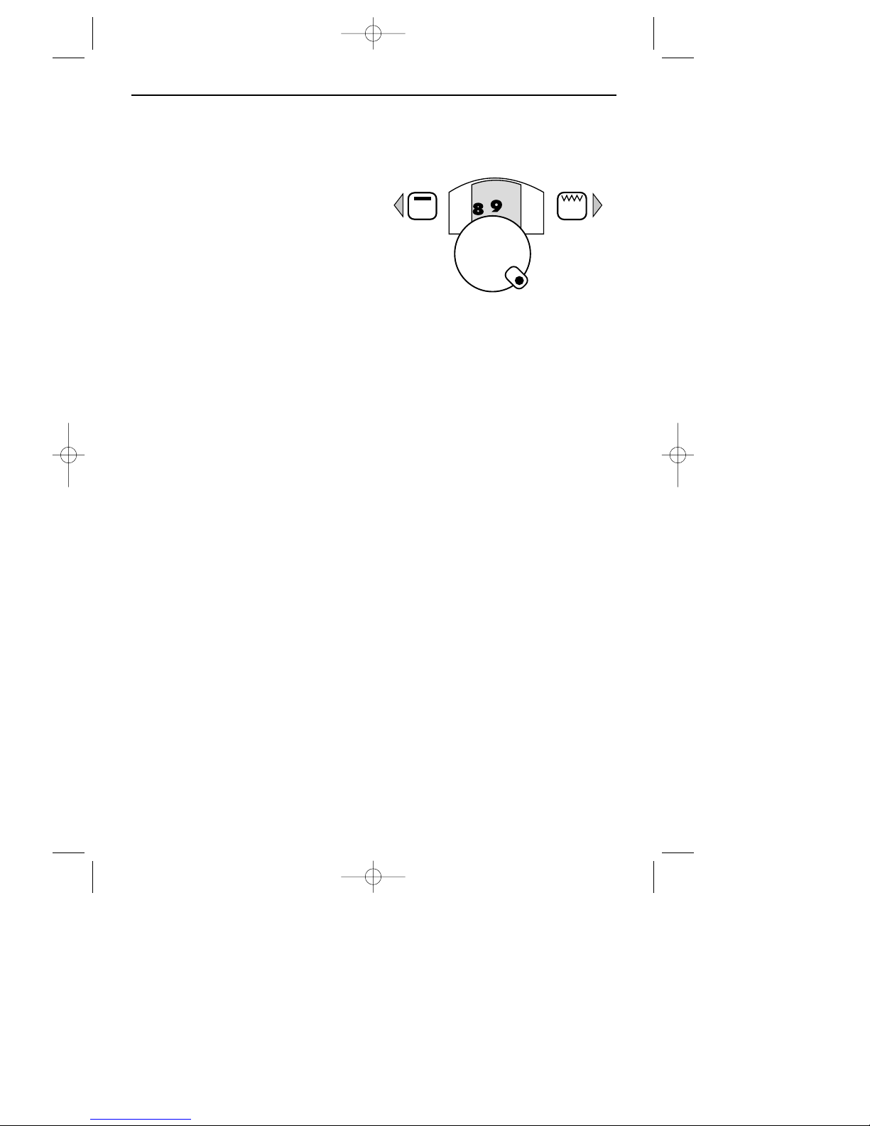
To turn on the top oven
Push in and turn the control knob anticlockwise to fully on (Gas Mark 9).
There is a short delay before ignition
(up to 10 seconds) and the automatic
ignition will continue to spark for a
short time after the burner has lit until
the flame is established.
Adjust to the required setting.
❏ The top oven bur ner may not come
on to the full rate unless the oven
door is closed.
❏ In the event of the burner flames
being accidentally extinguished,
turn off the burner control and do
not attempt to re-ignite the oven for
at least one minute.
TOP OVEN (CONVENTIONAL)
5
18291 01 04/11/2002 12:19 Page 7
Page 8
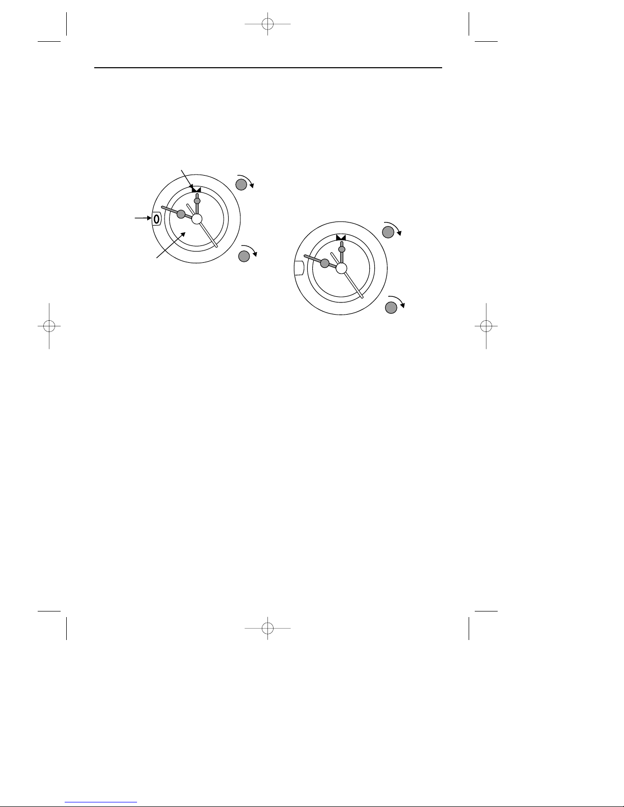
TO SET THE TIME OF DAY
Pull out the ST ART TIME knob and keep
it pulled out as you turn the hands of
the clock to the correct time.
MANUAL OPERATION
To turn on the oven
1.Turn the ST AR T TIME knob clockwise
until the INDICATOR is facing
twelve o’clock on the OUTER
CLOCK DIAL as shown.
2.Turn the COOK TIME knob clockwise, until 1 appears in the window.
To turn off the oven
Turn the cook time knob anticlockwise,
until 0 appears in the window.
11
10
7
8
INNER TIMER
DIAL
WINDOW
INDICATOR
COOK
TIME
START
TIME
9
6
5
4
3
2
1
XII
I
II
III
IV
V
VI
VII
VIII
X
XI
11
10
7
8
9
6
5
4
3
2
1
1
XII
I
II
III
IV
V
VI
VII
VIII
X
XI
ANALOGUE PROGRAMMER / CLOCK
6
18291 01 04/11/2002 12:19 Page 8
Page 9
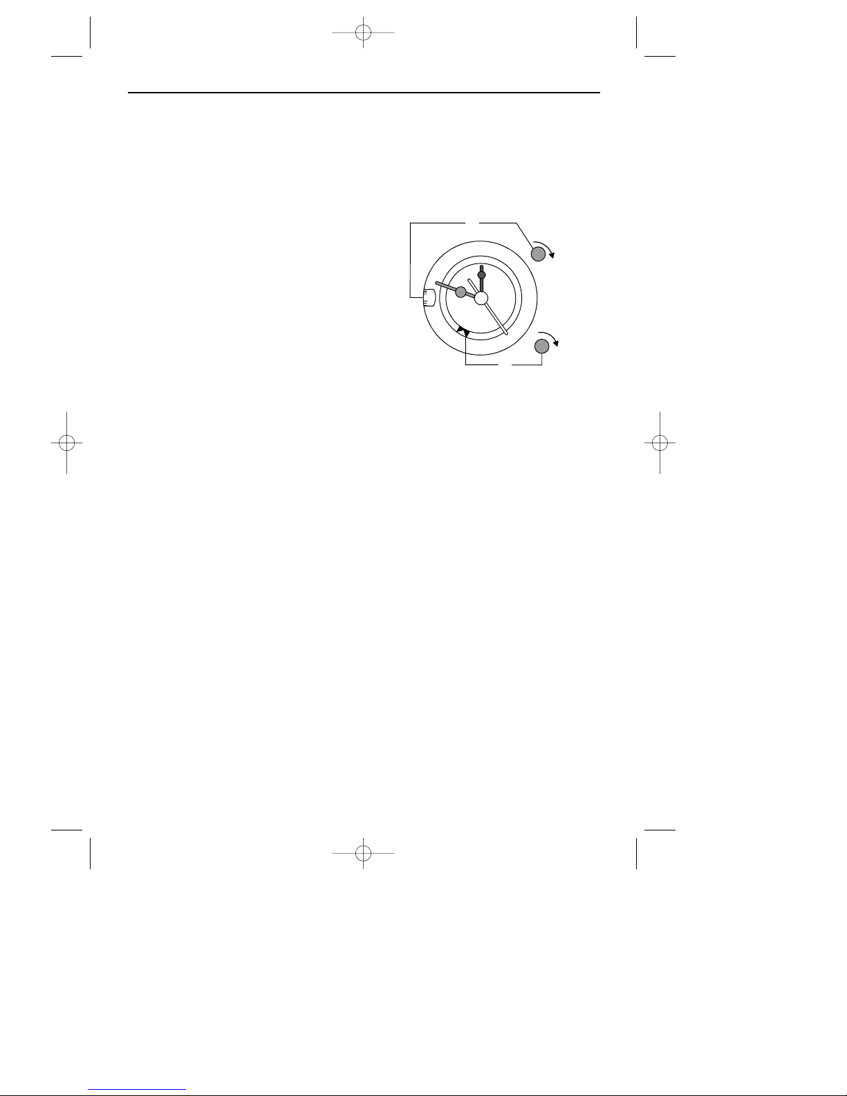
SEMI AUTOMATIC OPERATION
To set the cooking start time only
1.Turn the start time knob until the
INDICATOR faces the required time
for cooking to start on the inner
timer dial, eg; 5 o’clock as shown
opposite.
Turn the oven control knob to the
required setting.
Please note that the start time setting is
only accurate to within a few minutes.
To set the cooking stop time only
COOKING IS ALREADY STARTED, AND WILL
STOP AUTOMATICALLY
.
2.Turn the cook time knob clockwise,
until the length of cooking time you
require is showing in the window,
as shown opposite (eg; 120
minutes).
At the end of the cooking time, the
oven will automatically turn off and the
bell will ring for a few minutes before
it turns off.
To turn off the bell before it has
finished ringing, simply turn off the
oven manually by turning the cook
time knob clockwise until 0 appears in
the window.
AUTOMATIC OPERATION
Cooking starts automatically at the
selected time, and stops automatically
at the end of cooking time.
1.Turn the start time knob until the indicator faces the required time for
cooking to start on the inner timer
dial, eg; 5 o’clock as shown above.
2.Turn the cook time knob clockwise,
until the length of cooking time you
require is showing in the window
(eg; 120 minutes).
Turn the oven control knob to the
required setting.
At the end of automatic cooking
time the oven will automatically turn
off and the bell will ring for a few minutes before it turns off.
To turn off the bell before it has finished ringing, simply turn off the oven
manually by turning the cook time
knob clockwise until 0 appears in the
window.
11
10
7
8
9
6
5
4
3
2
1
120
XII
I
II
III
IV
V
VI
VII
VIII
X
XI
2
1
ANALOGUE PROGRAMMER / CLOCK
7
18291 01 04/11/2002 12:19 Page 9
Page 10
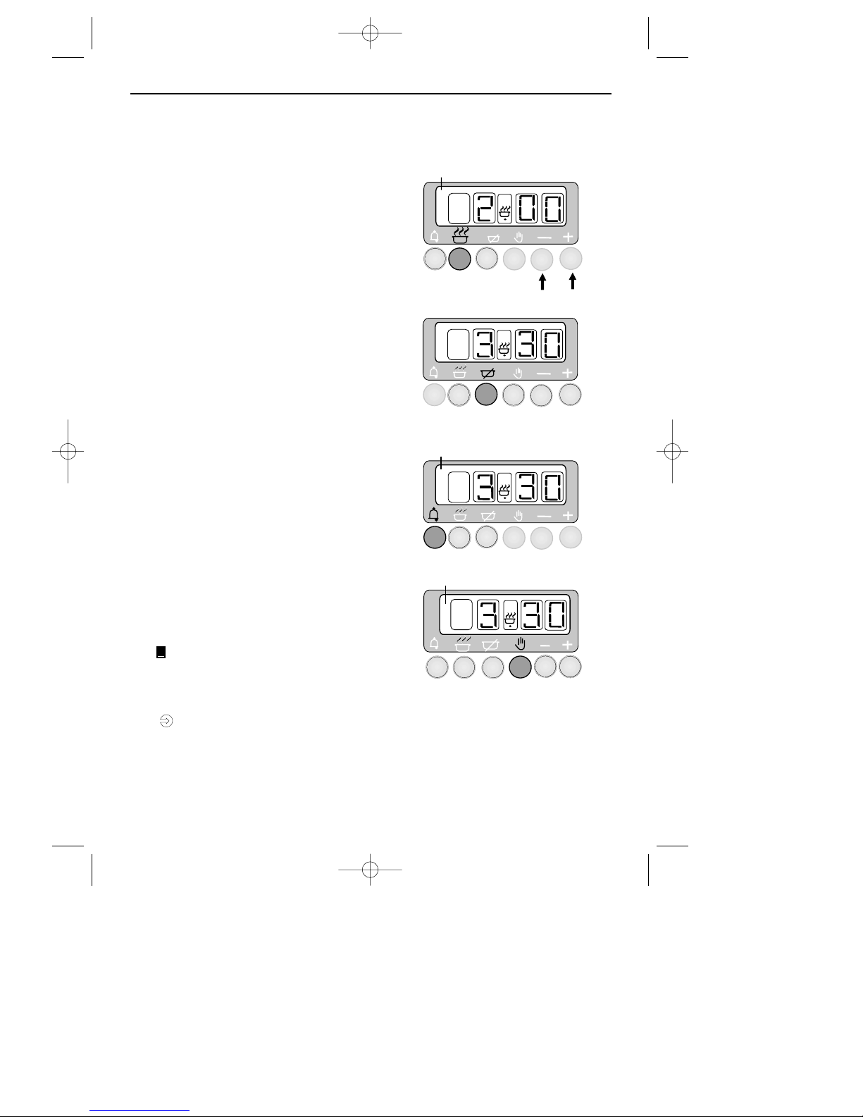
A
SEMI-AUTOMATIC COOKING
(EXAMPLE)
AUTO symbol
appears.
A
A
Press the 'COOK TIME' button, then use the
plus and minus buttons to set the display to
show the length of cooking time required.
e.g. 2 hours as shown.
The display will revert to show the time of
day, but you can press the cook time button
and the display will show how much cooking
time still remains on the clock.
Press the 'READY TIME' button, and the
display will show the actual time the oven
is going to switch off e.g. 3.30 as shown.
To switch off the alarm, press the
'MINUTE MINDER' button.
A(AUTO) Symbol
goes out
To cancel the automatic setting and return
the oven to manual operation, press the
manual button.
COOK
TIME
READY
TIME
MINUTE
MINDER
RETURN THE OVEN CONTROL KNOB
TO THE OFF POSITION.
A(AUTO) Symbol
will flash
To cancel any remaining cooking time
left on the clock before the alarm sounds,
press the manual button.
You have started cooking a meal or dish in
the oven, and want to set the time for the
oven to switch off.
MANUAL
MANUAL OPERATION
DIGITAL PROGRAMMER / CLOCK
8
18291 01 04/11/2002 12:19 Page 10
Page 11
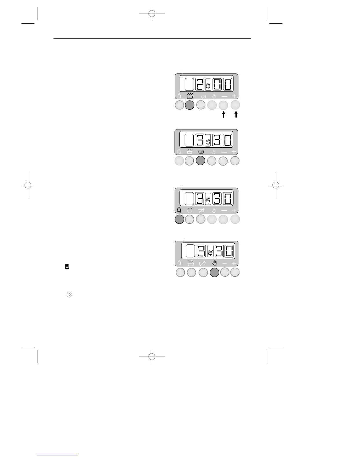
A
SEMI-AUTOMATIC COOKING
(EXAMPLE)
AUTO symbol
appears.
A
A
Press the 'COOK TIME' button, then use the
plus and minus buttons to set the display to
show the length of cooking time required.
e.g. 2 hours as shown.
The display will revert to show the time of
day, but you can press the cook time button
and the display will show how much cooking
time still remains on the clock.
Press the 'READY TIME' button, and the
display will show the actual time the oven
is going to switch off e.g. 3.30 as shown.
To switch off the alarm, press the
'MINUTE MINDER' button.
A(AUTO) Symbol
goes out
To cancel the automatic setting and return
the oven to manual operation, press the
manual button.
COOK
TIME
READY
TIME
MINUTE
MINDER
RETURN THE OVEN CONTROL KNOB
TO THE OFF POSITION.
A(AUTO) Symbol
will flash
To cancel any remaining cooking time
left on the clock before the alarm sounds,
press the manual button.
You have started cooking a meal or dish in
the oven, and want to set the time for the
oven to switch off.
MANUAL
MANUAL OPERATION
DIGITAL PROGRAMMER / CLOCK
9
18291 01 04/11/2002 12:19 Page 11
Page 12
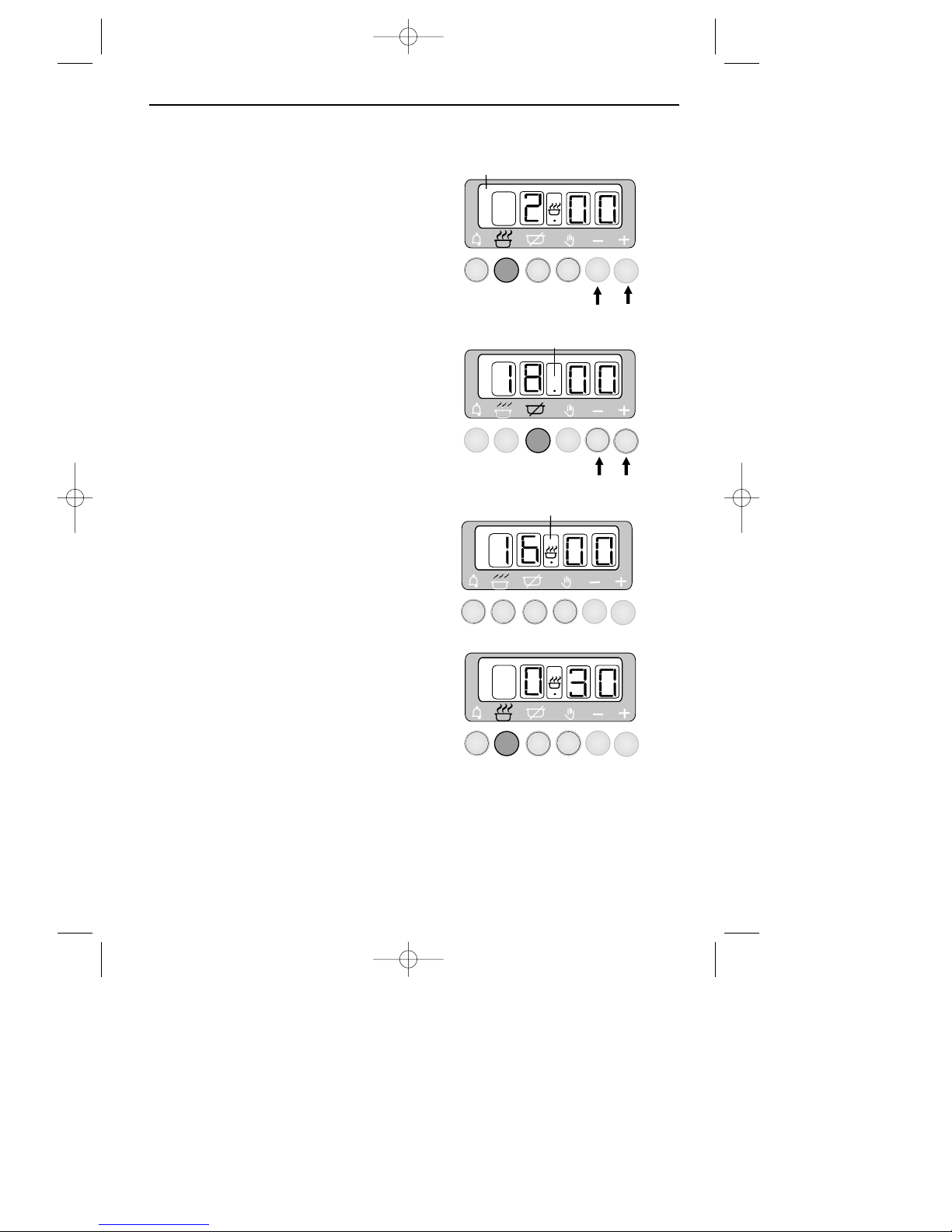
DIGITAL PROGRAMMER / CLOCK
COOK
TIME
COOK
TIME
FULLY AUTOMATIC COOKING
(EXAMPLE)
You want to set the time for the oven to switch
on, and then after the meal or dish is cooked,
to switch off.
A
A
AUTO symbol
appears.
Press the 'COOK TIME' button, then use the
plus and minus buttons to set the display to
show the length of cooking time required
e.g. 2 hours as shown.
Press the 'READY TIME' button and the
present ready time will be displayed,
but using the plus and minus buttons
you can set the display to show the
ACTUAL TIME you want the oven to
switch off e.g.18.00 hours
A
READY
TIME
The cookpot symbol will
disappear from the display.
The cookpot symbol will appear
on the display.
A
AFTER SETTING THE PROGRAMMER, TURN
THE OVEN CONTROL TO THE REQUIRED
TEMPERATURE
The oven will automatically switch on
at the calculated start time of 16.00
hours (4.00 pm).
A single press of the 'COOK TIME' button
shows the cooking time remaining before
the oven automatically switches off.
10
18291 01 04/11/2002 12:19 Page 12
Page 13
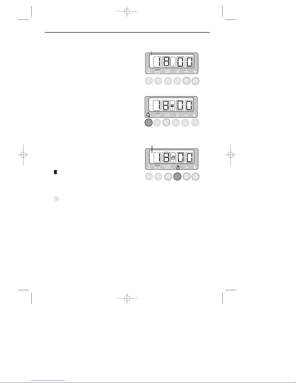
A
A(AUTO) Symbol
will flash
The oven will automatically switch off at
18.00 hours (6.00pm) and the alarm will
sound.
A
To switch off the alarm, press the minute
minder button.
MINUTE
MINDER
A(AUTO) symbol
goes out
To cancel the automatic setting and return
the oven to manual operation, press the
manual button.
RETURN THE OVEN CONTROL KNOB TO
THE OFF POSITION.
To cancel any remaining cooking time left
on the clock before the alarm sounds, press
the manual button.
DIGITAL PROGRAMMER / CLOCK
11
18291 01 04/11/2002 12:19 Page 13
Page 14
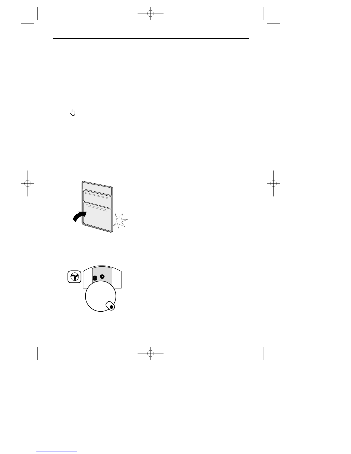
WHEN YOU ARE COOKING, KEEP
CHILDREN AWAY FROM THE VICINITY OF
THE OVEN
.
The oven cannot be used manually
when the programmer is set for
‘Automatic Operation’.
If A (Auto) is showing on the
programmer display, press the manual
button .
To turn on the main oven
The oven door must be
CLOSED for the
oven burner to ignite. The oven
burner will go out when the door is
opened but will re-light when the door
is closed again, this has no detrimental effect on the food being cooked.
Push in and turn the oven control knob
anticlockwise to Gas Mark 9.
Adjust to the required setting.
There is a short delay before ignition
(up to 10 seconds) and the automatic
ignition will continue to spark for a
short time after the burner has lit until
the flame is established. It can take up
to 60 seconds for the oven burner to
come on to full rate.
In the event of the burner flames being
accidentally extinguished, turn off the
burner control and do not attempt to
re-ignite the oven for at least one
minute.
Automatic operation
See ‘Programmer / Clock’ section.
Oven light
Press the light button on the facia
panel.
To replace an oven light bulb
Switch off the electricity supply to the
appliance at the socket, and wait until
the oven is cool before removing the
oven shelves. The lens cover on the
light can be removed by grasping the
lens cover and pulling away from the
side of the oven.
■ Please note that the oven light bulbs
are not covered by guarantee.
■ If it is found over a period of time
that the oven become hotter when
used at a particular temperature, then
the thermostat may need to be
replaced.
MAIN FAN OVEN
12
18291 01 04/11/2002 12:19 Page 14
Page 15
✘ DO NOT USE caustic pastes, abrasive
cleaning powders, coarse wire wool
or any hard implements, as they will
damage the surfaces.
✔ All parts of the oven can be safely
cleaned with a clean cloth wrung out
in hot soapy water. Switch off the
electricity supply to the appliance, and
let the oven cool before cleaning.
When removing stubborn deposits, we
recommend the following;
Vitreous enamel parts
G
RILL PAN
GRILL COMPARTMENT
OVEN FLOOR
✔ Use a mild cream cleaner.
Stay clean surfaces
M
AIN OVEN COMPARTMENT
Note: If you do a lot of open roasting,
you may feel the surfaces need an
occasional wipe.
M
OST TYPES OF CLEANING AGENT WILL
DAMAGE THESE SURFACES
.
✔ Only use a few drops of washing up
liquid in hot water. Wipe the surfaces
with a clean cloth wrung out in hot
soapy water, or when large splashes
of fat do not readily disappear, scrub
the area with a nylon brush or nylon
pan scourer, rinse well and heat the
oven to dry the linings.
Glass parts
F
ACIA PANEL
OUTER & INNER DOOR GLASS PANELS
Use a mild cream cleaner, rinse
thoroughly and dry with a soft cloth.
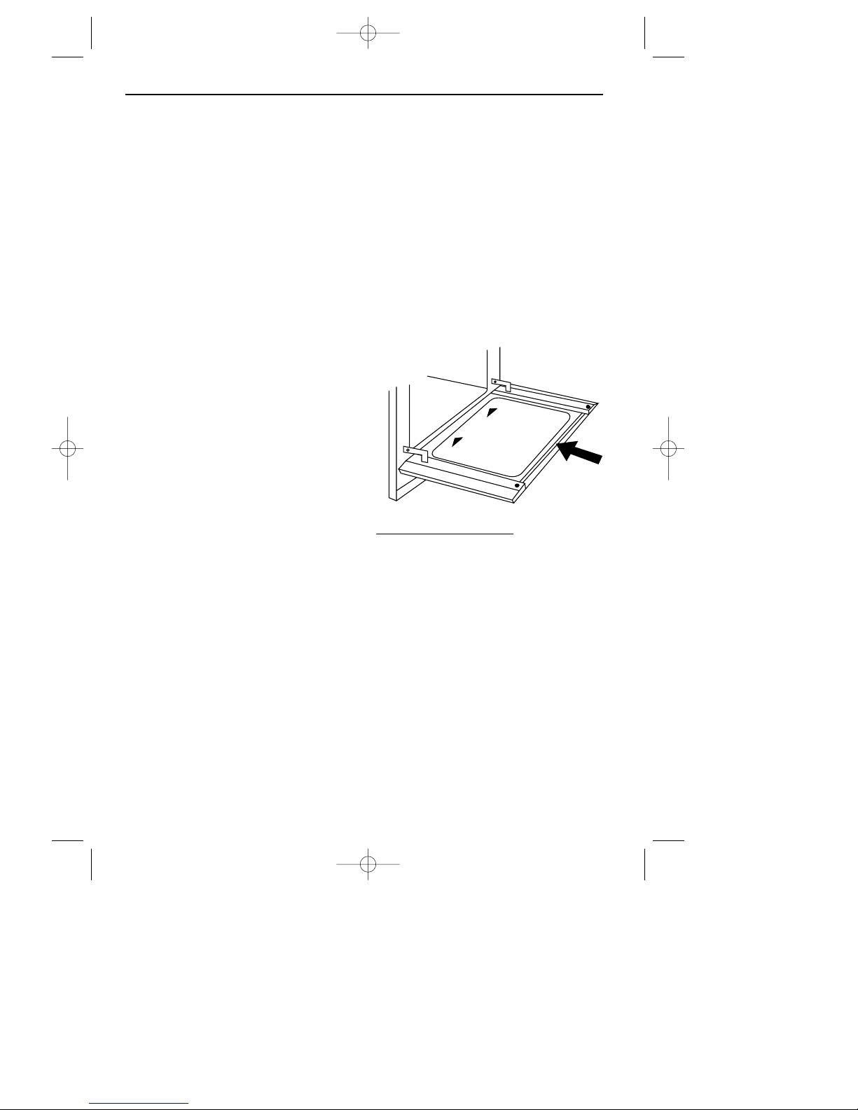
Important: the inner door glass panel
can be removed for cleaning but it
must be replaced the right way up as
shown (so the reflective side faces
inwards), and pushed fully in to the
stop position. To remove the glass
panel, open the door wide, hold the
top and bottom edges and slide out.
Anthracite models only
FACIA PANEL / OUTER DOOR GLASS
✔Only use a clean cloth wrung out in
hot soapy water, and dry with a soft
cloth.
Painted parts
O
VEN DOOR FRAME & HANDLE
OUTER FRAME TRIM
✔ Only use a clean cloth wrung out in
hot soapy water.
CLEANING
SLIDE
IN
SLIDE
IN
THIS SIDE UP
13
18291 01 04/11/2002 12:19 Page 15
Page 16
Chrome plated parts
O
VEN SHELVES
OVEN SHELF RUNNERS
✔ Use a moist soap pad, eg; Brillo
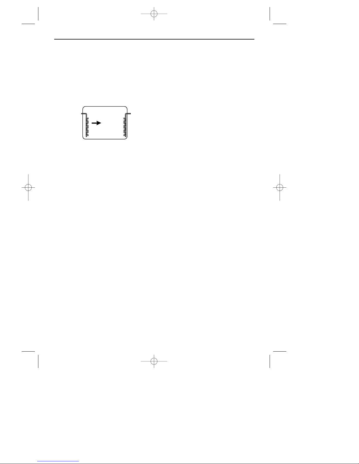
Note: Oven shelf runners can be
removed for cleaning. Grasp the runners and slide out of the hanging holes
as shown.
Ceramic grill glass
After using the oven or grill, wait until
the grill glass is cool before giving it a
quick wipe over. Most splashes on the
grill glass will burn off as the grill is
used, but if necessary, it can be
cleaned using a ceramic hob cleaner ,
eg; Hob Brite, or a moist soap pad.
When cleaning, do not exert excessive
pressure on the grill glass.
✔ For removing stubborn deposits, we
recommend the use of a ceramic hob
scraper.
Lacquered brass parts
H
ANDLE TRIMS (HERITAGE)
✔ Only use a clean cloth wrung out in
hot soapy water.
Stainless steel
S
TAINLESS STEEL MODELS
✘ Do not use undiluted bleach or any
products containing chlorides, as they
can permanently damage the steel.
✔Only use a clean cloth wrung out in
hot soapy water, and dry with a soft
cloth.
Some foods are corrosive, eg; vinegar, fruit juices and salt, and they can
mark or damage stainless steel if they
are left on the surface for any length of
time.
Sharp objects can mark the surface of
stainless steel, but will become less
noticeable with time.
Oven shelf deflector
This can be removed for cleaning grasp the deflector with both hands
and press towards the oven shelf.
✔ Use a mild cream cleaner, rinse
thoroughly and dry with a soft cloth.
CLEANING
14
18291 01 04/11/2002 12:19 Page 16
Page 17

Before you start, check that your appliance is suitable for the gas supply in your
house, ie; Natural Gas or LP Gas. The gas category is clearly marked on the
data badge.
Regulations & Standards . . . . . . . . . . . . . . . . . . . . . . . . . . . . 16
Ventilation Requirements . . . . . . . . . . . . . . . . . . . . . . . . . . . . . 16
Installing the appliance . . . . . . . . . . . . . . . . . . . . . . . . . . . . . 17
Connect to the electricity supply . . . . . . . . . . . . . . . . . . . . . . . 18
Connect to the gas supply . . . . . . . . . . . . . . . . . . . . . . . . . . . 19
Secure appliance to housing unit . . . . . . . . . . . . . . . . . . . . . . . 19
Commissioning . . . . . . . . . . . . . . . . . . . . . . . . . . . . . . . . . . . 20
INSTALLATION INSTRUCTIONS
15
18291 01 04/11/2002 12:19 Page 17
Page 18
The 900GTF appliance is
designed for use on Natural Gas,
and must not be supplied with
any other gas.
The 900GTF LP appliance is
designed for use on Propane or
Butane, and must not be used on
any other gas.
W
ARNING;THIS APPLIANCE MUST BE EARTHED
.
IN THE UK THE REGULATIONS AND
STANDARDS ARE AS FOLLOWS
:
1.Gas Safety Regulations 1984
(Installation and Use) as amended
1990.
2.Building Regulations - Issued by the
Department of the Environment.
3.Building Standards (Scotland)
(Consolidated) - Issued by the
Scottish Development Department.
4.The current I.E.E. Wiring
Regulations.
5.Electricity at Work Regulations
1989.
6. B.S. 6172 Installation & Servicing
Instructions for this appliance.
Ventilation Requirements
■ The room containing the appliance
should have an air supply in accordance with B.S. 5440: Part 2: 1989:
■ All rooms require an openable window, or equivalent, and some rooms
will require a permanent vent as well.
■ For room volumes up to 5 m
3
an air
vent of 100 cm
2
is required.
■ If the room has a door that opens
directly to the outside, or the room
exceeds 10 m
3
NO AIR VENT is
required.
■ For room volumes between 5 m
3
and
10 m
3
an air vent of 50 cm2is
required.
■ If there are other fuel burning appliances in the same room, B.S. 5440:
Part 2: 1989 should be consulted to
determine the air vent requirements.
■ This appliance must not be installed in
a bed sitting room of less than 20 m
3
or in a bathroom or sower room.
Windows and permanent vents should
therefore not be blocked or removed
without first consulting a CORGI gas
installer.
LP Gas only
Do not install this appliance in a room
below ground level. This does not preclude installation into rooms which are
basements with respect to one side of
the building, but open to ground level on
the opposite side.
FAILURE TO INSTALL APPLIANCES
CORRECTLY IS DANGEROUS AND COULD
LEAD TO PROSECUTION
.
INSTALLATION INSTRUCTIONS
In your own interest and that of
safety, it is the law that all gas
appliance be installed and serviced
by competent persons. CORGI
registered installers undertake to
work to satisfactory standards.
16
18291 01 04/11/2002 12:19 Page 18
Page 19
Do not lift the appliance by the
door handle
■ Remove the fixing screws from the
polythene bag on the top of the
appliance, but leave the appliance
in the base tray packaging until you
are ready to install it.
■
NOTE: When removing the appli-
ance from the base tray packaging
care should be taken to ensure the
outer frame trim is not damaged.
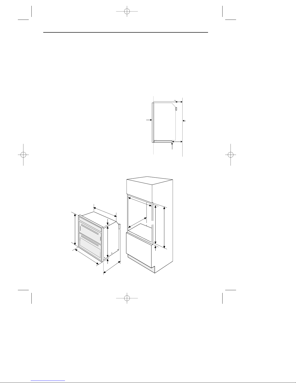
❏ When installed in a typical 600 mm
deep built in housing unit, the false
back should be removed from the
housing unit, to provide the necessary depth for installation.
❏ When the false back is removed, it
is normally the case that the support
shelf for the appliance leaves a gap
between the back edge of the support shelf and the rear wall of
approximately 80 mm.
❏ If no gap occurs between the back
edge of the shelf and the wall
behind the unit, we recommend that
a gap of at least 30 mm is made by
shortening the support shelf.
❏ If a top shelf is fitted, it must have a
gap at the rear of at least 50 mm,
but ensure items will not be dropped
behind the oven.
I
MPORTANT: DO NOT MODIFY THE OUTER
PANELS OF THIS APPLIANCE IN ANY WAY
.
INSTALLATION INSTRUCTIONS
min
560 mm
550 mm
min
min
880
mm
869
mm
892
mm
min
888
mm
min
7 mm
547 mm
595 mm
550 mm
17 mm
6 mm
30 - 80
mm
BACK EDGE OF
SUPPORT SHELF
FRONT OF
OVEN
REAR
WALL
50
mm
17
18291 01 04/11/2002 12:19 Page 19
Page 20
Connect to the electricity supply
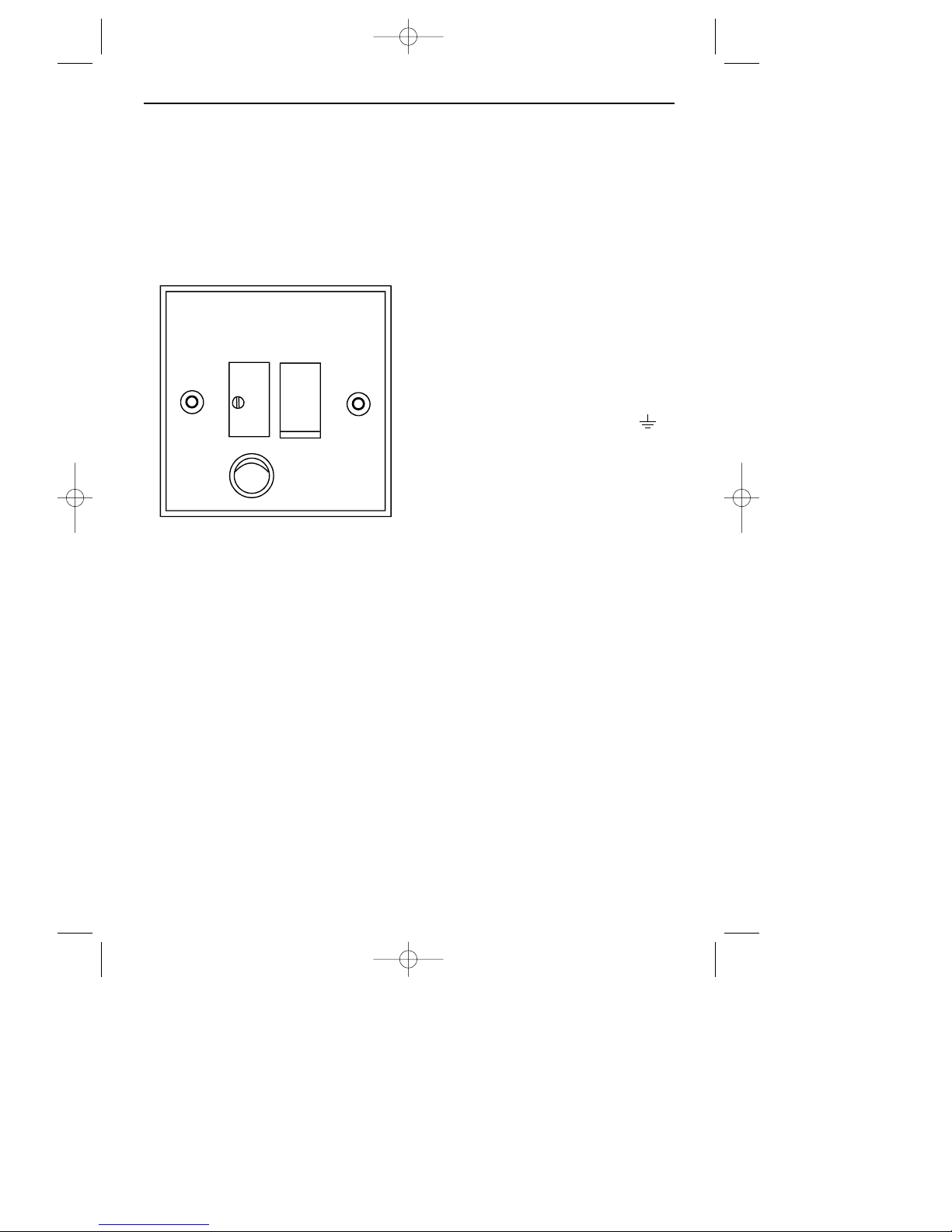
This appliance must be connected by a
competent person, using fixed wiring
via a
DOUBLE POLE SWITCHED FUSED SPUR
OUTLET
.
We recommend that the appliance is
connected by a qualified electrician,
who is a member of the N.I.C.E.I.C.
and who will comply with the I.E.E.
and local regulations.
WARNING:
T
HIS APPLIANCE MUST BE EARTHED.
■ The wires in the mains lead are
coloured in accordance with the following code:
◆ Green and Yellow = Earth
◆ Blue = Neutral
◆ Brown = Live
As the colours of the wires in the mains
lead for the appliance, may not correspond with the coloured markings
identifying the terminals in your spur
box, proceed as follows:
1.The wire which is coloured green
and yellow must be connected to
the terminal marked E (Earth) or
coloured Green.
2.The wire which is coloured blue
must be connected to the terminal
marked N (Neutral, or coloured
Black.
3. The wire which is coloured brown
must be connected to the terminal
marked L (Live), or coloured Red.
INSTALLATION INSTRUCTIONS
FUSE
ON
USE A
3 AMP FUSE
DOUBLE POLE SWITCHED
FUSED SPUR OUTLET
18
18291 01 04/11/2002 12:19 Page 20
Page 21
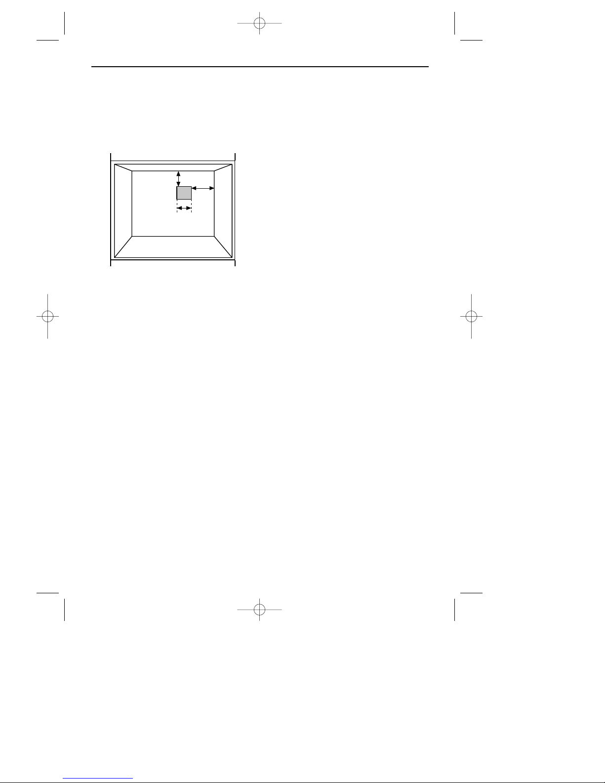
Connect to the gas supply
1.The inlet to the appliance is
1
⁄2” BSP
internal situated at the rear top right
corner.
2.Fit the bayonet connection to the
wall in the shaded area as shown.
3.Use a 900 mm - 1125 mm length of
flexible connector and make sure it
does not block the fan inlet and cannot come into contact with moving
parts of the cabinetry, eg; drawers
and doors.
4.Natural Gas
Flexible connections should be to
B.S. 699. Parts of the appliance
likely to come into contact with a
flexible connecter have a temperature rise less than 70
o
C.
LP Gas
For flexible connections use a bayonet type hose, suitable for use on LP
Gas up to 50 mbar pressure and
70
o
C temperature rise. The flexible
hose should be coloured black with
a red stripe, band or label. If in
doubt, contact your supplier.
5. Rigid connections must be accessible to disconnect for servicing. Cut
a 150 mm square hole in the right
hand rear corner of the support
shelf for the supply pipe.
6. Make sure all connections are gas
sound.
Secure appliance into housing
unit
1.Open the oven door.
2.Use 2 screws through the 2 top
corner holes to secure the appliance
to the housing.
INSTALLATION INSTRUCTIONS
Rear
Wall
60 mm
100
mm
150 mm
square
19
18291 01 04/11/2002 12:19 Page 21
Page 22

Commissioning
Burner aeration
All burners have fixed aeration and no
adjustment is possible.
Pressure setting
Natural Gas 20 mbar
Butane 28 mbar
Propane 37 mbar
The pressure test point is on the side of
the manifold inlet block.
Oven / Grill light
Press the light switch on the facia
panel.
Programmer
The programmer must be set to the
time of day before the main oven can
be used manually - see the
‘P
ROGRAMMER / CLOCK’ section to ‘Set
the time of day’.
Electrical Systems Check
In the event of an electrical fault, the
preliminary electrical system check
(earth continuity, short circuit, polarity
and resistance to earth) must be carried out. There is also a F
AULT FINDING
SECTION in the SERVICING INSTRUCTIONS.
Ignition
The automatic ignition continues to
spark for a short time after the burner
flame has lit until the flame is
established.
Grill
1.The door must be open for the grill
burners to ignite.
2. Push in the control knob and turn
clockwise to the grill setting.
3. Close the door and check that the
burner goes out. The grill burner
will re-ignite when the door is
opened again.
Main Oven
1.The door must be closed for the
oven burner(s) to ignite. The oven
burner will go out when the door is
opened but will re-light when the
door is closed again.
2.Push in and turn the oven control
knob anticlockwise to fully on.
3.Adjust to the required setting.
Note: The oven burner operates at a
low rate for up to 60 seconds until the
flame supervision device opens and
full gas rate is obtained.
Top Oven
1. Push in and turn the control knob
anticlockwise to fully on.
2.Adjust to the required setting.
Before leaving the installation
Show the customer how to ignite the
oven and grill and give them this handbook.
Thank you.
INSTALLATION INSTRUCTIONS
20
18291 01 04/11/2002 12:19 Page 22
Page 23

BEFORE SERVICING - DISCONNECT THE GAS AND ELECTRICAL SUPPLIES
AFTER SERVICING - CHECK GAS SOUNDNESS
Functional Flow Diagram . . . . . . . . . . . . . . . . . . . . . . . 22
Fault finding . . . . . . . . . . . . . . . . . . . . . . . . . . . . . . . 23 - 31
Wiring Diagram . . . . . . . . . . . . . . . . . . . . . . . . . . . . 32
1. Facia glass panel . . . . . . . . . . . . . . . . . . . . . . . . 33
2. Remove appliance from housing . . . . . . . . . . . . . . 33
3. Door glass panel(s) . . . . . . . . . . . . . . . . . . . . . . . 33
4. Oven light bulb(s) . . . . . . . . . . . . . . . . . . . . . . . . 33
5. Grill Glass . . . . . . . . . . . . . . . . . . . . . . . . . . . . . 34
6. Main oven burner / electrode / injector . . . . . . . . . 34
7. FSD valve (main oven) . . . . . . . . . . . . . . . . . . . . . 34
8. Top oven burner / electrode / injector . . . . . . . . . . 34
9. FSD valve (top oven) . . . . . . . . . . . . . . . . . . . . . . 35
10. Grill injector . . . . . . . . . . . . . . . . . . . . . . . . . . . . 35
11. Grill burner . . . . . . . . . . . . . . . . . . . . . . . . . . . . 35
12. Grill electrode . . . . . . . . . . . . . . . . . . . . . . . . . . . 35
13. Double solenoid valve (grill and top oven) . . . . . . . . 36
14. Light switch / Neon light(s) . . . . . . . . . . . . . . . . . . 36
15. Logic control pcb . . . . . . . . . . . . . . . . . . . . . . . . . 36
16. Thermostat(s) . . . . . . . . . . . . . . . . . . . . . . . . . . . 36
17. Cooling fan . . . . . . . . . . . . . . . . . . . . . . . . . . . . 37
18. Door switch(es) . . . . . . . . . . . . . . . . . . . . . . . . . . 37
19. Thermal cutout . . . . . . . . . . . . . . . . . . . . . . . . . . 37
20. Pressure switch . . . . . . . . . . . . . . . . . . . . . . . . . . 37
21. Ignition generator . . . . . . . . . . . . . . . . . . . . . . . . 37
22. Oven light fitting(s) . . . . . . . . . . . . . . . . . . . . . . . 38
23. Oven and grill micro-switches . . . . . . . . . . . . . . . . 38
24. Convection fan . . . . . . . . . . . . . . . . . . . . . . . . . . 38
25. Single solenoid valve (main oven) . . . . . . . . . . . . . 38
26. Fan timer relay board . . . . . . . . . . . . . . . . . . . . . 38
27. Programmer / Clock . . . . . . . . . . . . . . . . . . . . . . 38
28. Door frame . . . . . . . . . . . . . . . . . . . . . . . . . . . . 39
29. Door seal(s) . . . . . . . . . . . . . . . . . . . . . . . . . . . . 39
SERVICING INSTRUCTIONS
21
18291 01 04/11/2002 12:19 Page 23
Page 24
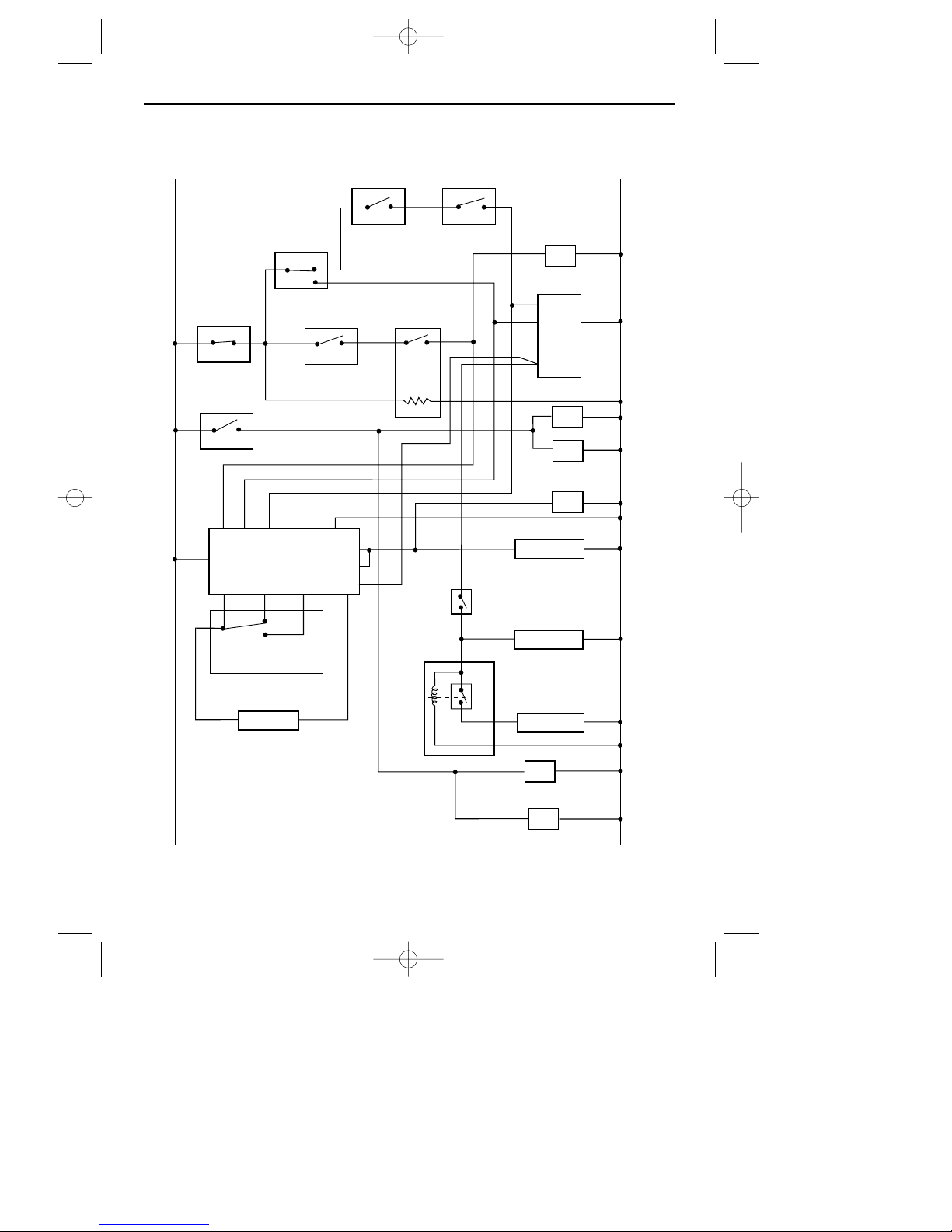
FUNCTIONAL FLOW DIAGRAM
L
N
L1
L2
L3
L
SL2
SL1
C
NC
NO
N
SL3
GRILL
SWITCH
TOP OVEN
SWITCH
THERMAL
CUTOUT
MAIN OVEN
SWITCH
PROGRAMMER
GRILL DOOR
SWITCH
MAIN OVEN
INDICATOR
RE-IGNITER
TOP
LIGHTS
TOP
INDICATOR
DOUBLE
SOLENOID
OVEN
DOOR
SWITCH
SINGLE
SOLENOID
MAIN OVEN
FAN
BOTTOM
LIGHTS
FAN
RELAY
BOARD
PRESSURE
SWITCH
LOGIC CONTROL
PCB
LIGHT
SWITCH
22
18291 01 04/11/2002 12:19 Page 24
Page 25
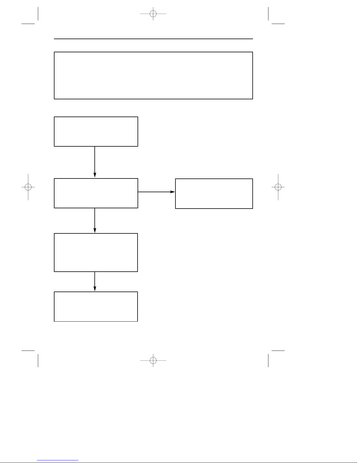
FAULT FINDING ELECTRICAL SYSTEMS - CHART 1
Before commencing appliance checks, ensure that the house
electrical system is correct at the outlet used for the appliance.
FAULT FINDING
SWITCH POWER ON TO
APPLIANCE
PRESS LIGHT BUTTON ON
THE FACIA.
LIGHTS COME ON?
SET PROGRAMMER FOR
MANUAL OPERATION.
SEE ‘PROGRAMMER / CLOCK’
IN USER’S SECTION.
GO TO CHART 2 OR 3
CHECK MAINS
AND / OR FUSE
YES
NO
YES
YES
23
18291 01 04/11/2002 12:19 Page 25
Page 26
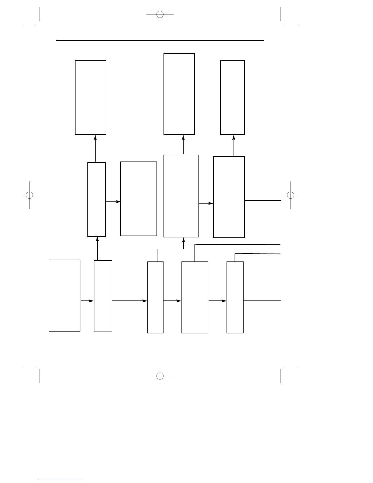
CHART 2 (GRILL)
FAULT FINDING
SPARKING STARTS
TURN CONTROL KNOB
TO GRILL POSITION,
OPEN TOP DOOR.
GAS LIT AT GRILL
CHECK FOR 230V AT
GRILL SWITCH OUTPUT.
CHECK FOR 230V AT C ON
PRESSURE SWITCH AND
LOGIC CONTROL PCB.
CHECK FOR 230V FROM
GRILL SWITCH THROUGH
DOOR SWITCH TO L3 ON
LOGIC CONTROL PCB.
CHECK WIRING FROM
GRILL SWITCH THROUGH
DOOR SWITCH TO L3
ON IGNITION UNIT
HAS FAN STARTED?
NEON INDICATOR
LIGHTS UP
FAN STARTS
REPLACE LOGIC CONTROL
PCB. SEE ‘SERVICING
INSTRUCTIONS’.
RECTIFY WIRING OR
DOOR SWITCH
YES
NO
NO
NO
NO
NO
NO
NO
YES
YES
YES
YES
YES
YES
24
18291 01 04/11/2002 12:19 Page 26
Page 27
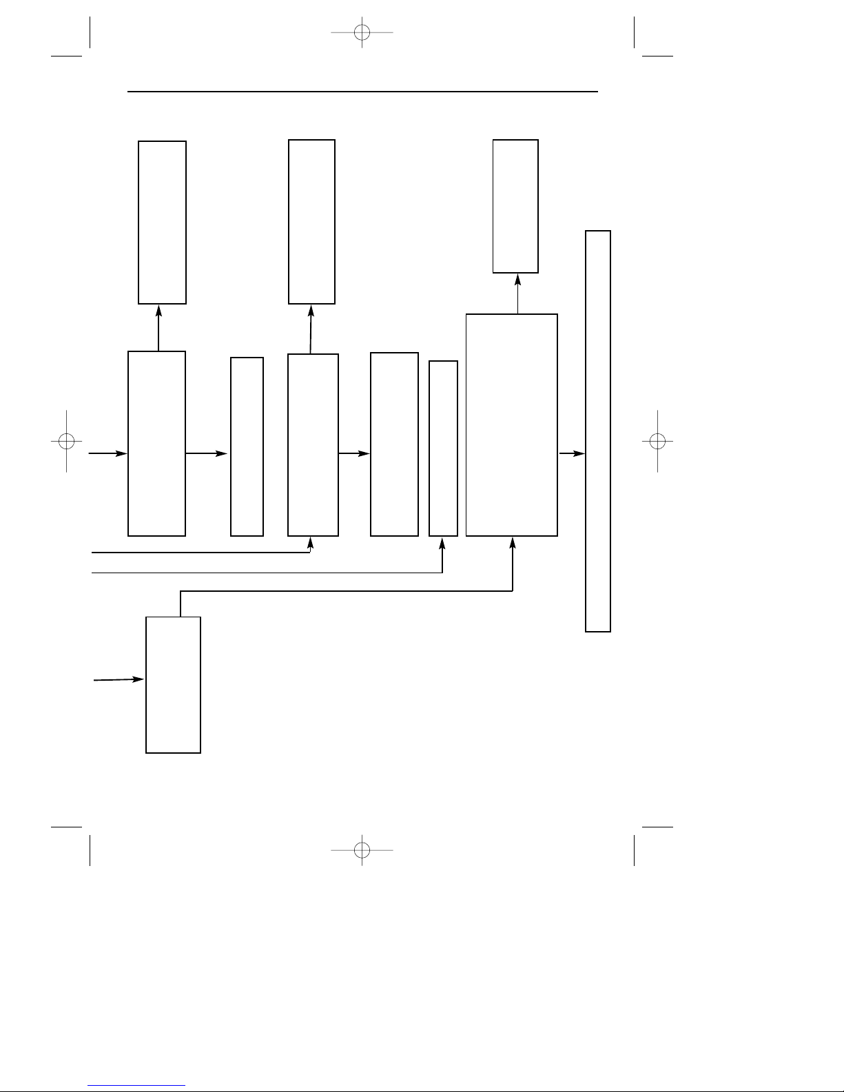
FAULT FINDING
SPARKING CEASES
AFTER PERIOD.
CHECK FOR 230V ACROSS
FAN CONNECTIONS.
REPLACE FAN
IS GAS LIGHTING AT GRILL
BURNER.
RECTIFY WIRING OR
REPLACE NEON INDICATOR.
GO TO CHART 4
CHECK IGNITION ELECTRODES
WHEN CORRECTLY POSITIONED,
CHECK HT LEADS ARE NOT DAM-
AGED, AND ARE CONNECTED
CORRECTLY.
RECTIFY WIRING
GO TO CHART 4
RECTIFY
REPLACE IGNITION UNIT, SEE ‘SERVICING INSTRUCTIONS’.
NO
NO
YES
NO
NO
YES
YES
25
18291 01 04/11/2002 12:19 Page 27
Page 28
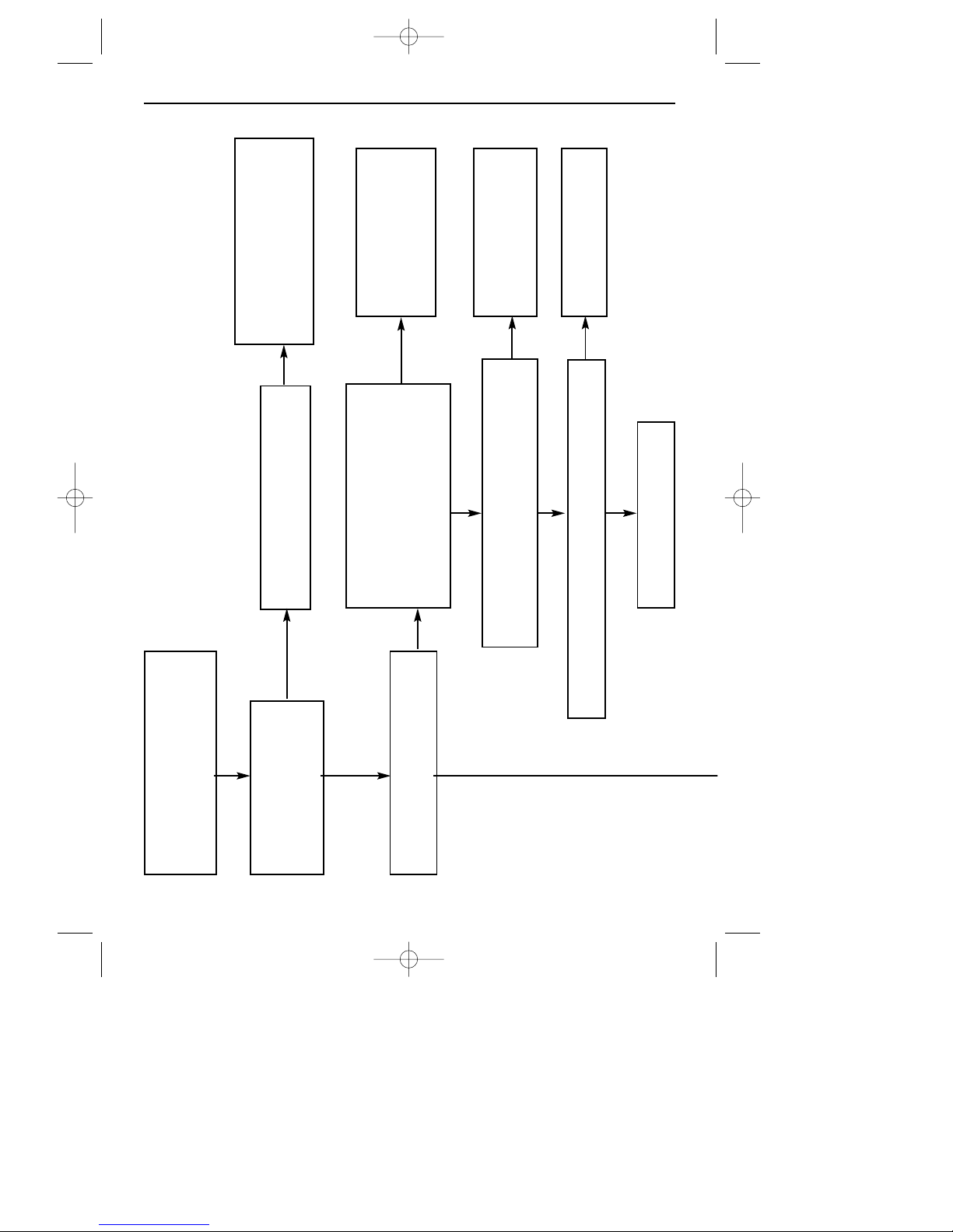
CHART 3 (MAIN OVEN)
FAULT FINDING
CHECK FOR 230V AT ‘C’ ON PRESSURE
SWITCH AND LOGIC CONTROL PCB
RECTIFY WIRING
CHECK FOR 230V FROM
OVEN SWITCH THROUGH
PROGRAMMER RELAY TO L1
ON LOGIC CONTROL PCB.
REPLACE LOGIC
CONTROL PCB.
HAS OVEN FAN STARTED
RECTIFY WIRING OR
PROGRAMMER
COOLING FAN OPERATES
CHECK FOR 230V AT OVEN
SWITCH AND THROUGH
PROGRAMMER RELAY
REPLACE FAN
CHECK FOR 230V ACROSS FAN CONNECTIONS
IGNITION GENERATOR
STARTS SPARKING
TURN OVEN CONTROL KNOB
TO DESIRED SETTING
26
18291 01 04/11/2002 12:19 Page 28
Page 29
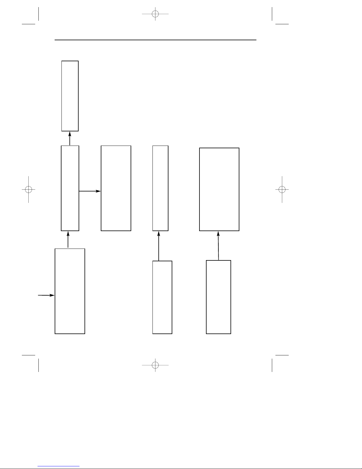
FAULT FINDING
NEON INDICATOR LIGHTS
CHECK IGNITION ELECTRODE
IS CORRECTLY POSITIONED.
CHECK HT LEAD IS NOT
DAMAGED
GO TO CHART 4
GO TO CHART 4
RECTIFY WIRING, OR REPLACE
NEON INDICATOR.
IS GAS LIGHTING AT BURNER
SPARKING CEASES AFTER
PERIOD.
GAS LIT AT BURNER
27
18291 01 04/11/2002 12:19 Page 29
Page 30
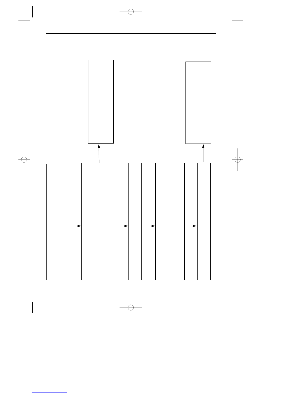
FAULT FINDING
SPARKING STARTED.
NEON INDICATOR NOT LIT. NO GAS AT BURNER.
BRIDGE FROM ‘C’ ON PRESSURE SWITCH, TO L1
OR L2 ON LOGIC CONTROL PCB, WITH A SUIT-
ABLE DOUBLE ENDED TEST LEAD
NEUTRAL WIRE TO SOLENOID, OR
SOLENOID FAULTY.
GO TO CHART 2 (GRILL) OR CHART
3 (MAIN OVEN) OR CHART 5 (TOP
OVEN.
SOLENOID OPERATES WITH AUDIBLE CLICK
COOLING FAN STARTS OPERATING
REMOVE BACK FROM APPLIANCE, SWITCH ON
POWER AND SET PROGRAMMER TO MANUAL.
TURN CONTROL KNOB TO OVEN OR GRILL POSI-
TION AND OPEN THE OVEN DOOR.
CHART 4
NO
NO
YES
YES
YES
YES
YES
28
18291 01 04/11/2002 12:19 Page 30
Page 31
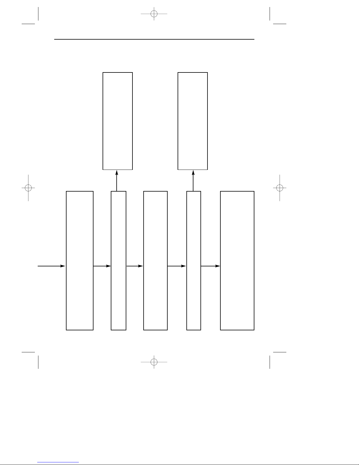
FAULT FINDING
BRIDGE FROM ‘C’ ON PRESSURE SWITCH TO NC
CONNECTION ON LOGIC CONTROL PCB.
NC WIRE FROM PRESSURE SWITCH
TO LOGIC CONTROL PCB IS FAULTY
LOGIC CONTROL PCB FAULTY.
TO REPLACE SEE ‘SERVICING
SECTION’.
PRESSURE SWITCH IS FAULTY OR LOW PRESSURE
TUBE IS BLOCKED, SPLIT OR PULLED OUT OF HOLE
IN BACK PANEL.
SOLENOID OPERATES
BRIDGE FROM ‘C’ TO NC CONNECTION ON PRES-
SURE SWITCH
SOLENOID OPERATES
NO
NO
YES
YES
YES
YES
29
18291 01 04/11/2002 12:19 Page 31
Page 32
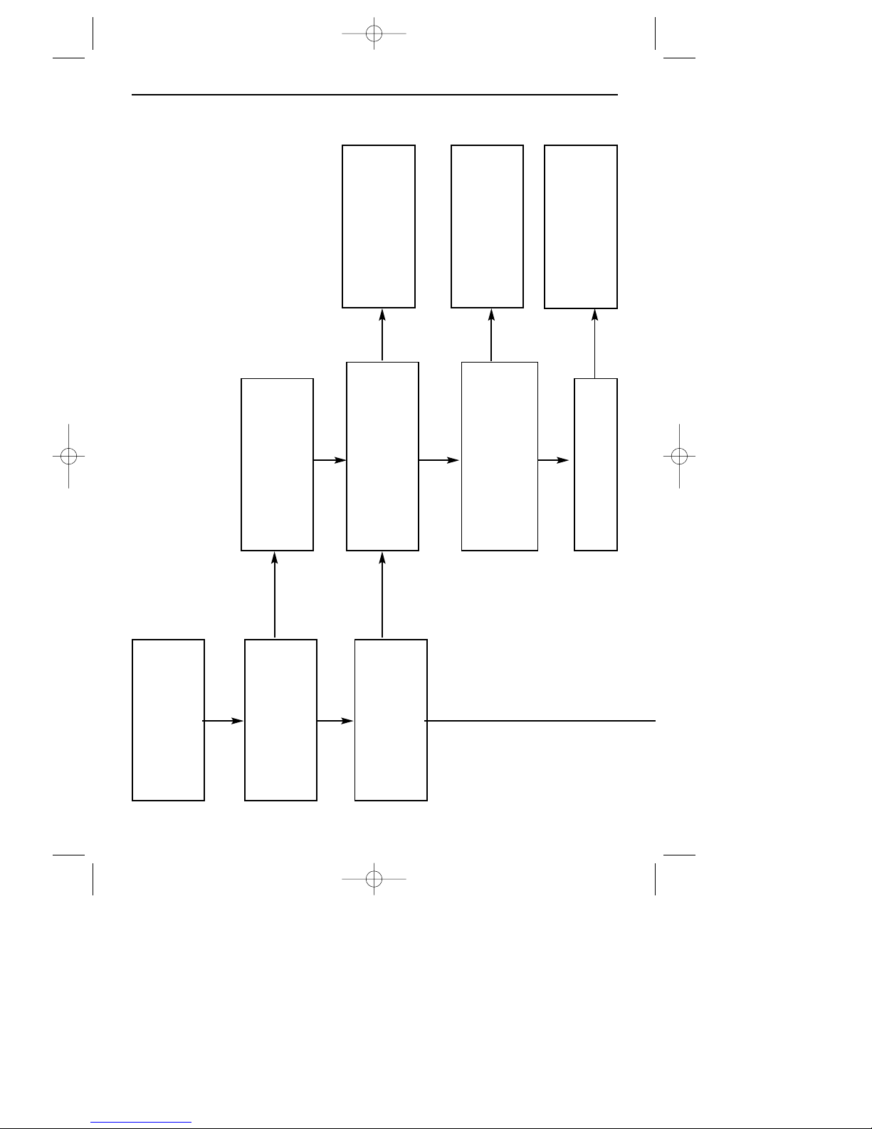
FAULT FINDING
CHART 5 (TOP OVEN)
REPLACE FAN
CHECK FOR 230V AT ‘C’
ON PRESSURE SWITCH
AND LOGIC CONTROL PCB
CHECK FOR 230V AT
OVEN SWITCH AND
IGNITION UNIT
CHECK FOR 230V FROM
OVEN SWITCH TO L2 ON
LOGIC CONTROL PCB
COOLING FAN
OPERATES
RECTIFY WIRING
REPLACE LOGIC
CONTROL PCB
RECTIFY WIRING OR
PROGRAMMER
IGNITION GENERATOR
STARTS SPARKING
TURN CONTROL KNOB
TO OVEN POSITION
NO
NO
NO
NO
NO
YES
YES
YES
YES
YES
YES
30
18291 01 04/11/2002 12:19 Page 32
Page 33
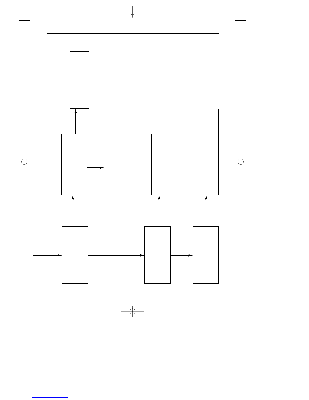
FAULT FINDING
NEON INDICATOR
LIGHTS?
GO TO CHART 4
IS GAS LIGHTING AT
BURNER?
CHECK IGNITION ELECTRODE IS
CORRECTLY POSITIONED. CHECK HT
LEAD IS NOT DAMAGED
SPARKING CEASES
AFTER PERIOD?
GO TO CHART 4
RECTIFY WIRING OR
REPLACE NEON
INDICATOR
GAS LIT AT BURNER?
NO
NO
NO
NO
YES
YES
31
18291 01 04/11/2002 12:19 Page 33
Page 34
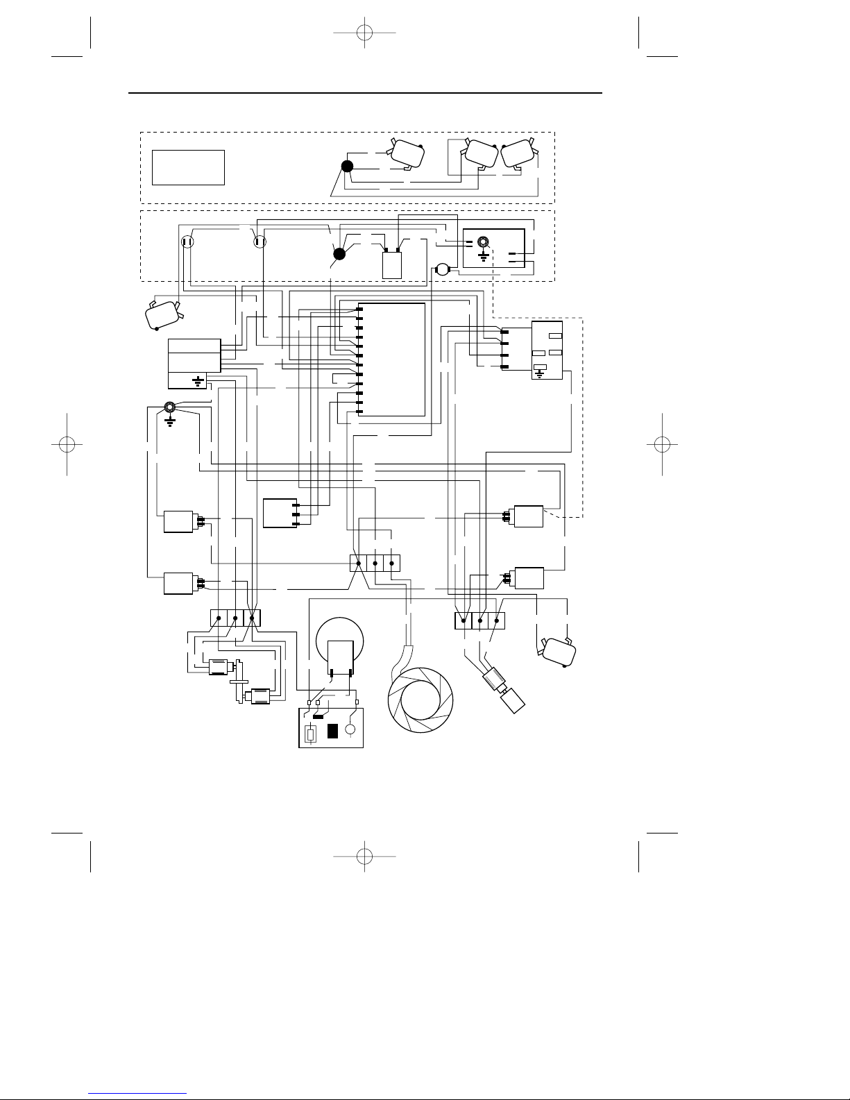
WIRING DIAGRAM
08 17429 03 / d126703
Wiring Colour Code:
Bk = Black, Bu = Blue, Br = Brown, Or = Orange, R = Red, W = White, Y = Yellow
Front view of inner facia panel
PROGRAMMER
C
C
NC
NC
NO
NO
C
NC
NO
R
Or
Bn
Y
Bn
R
LIGHT
LIGHT
C
NC
NO
L2
L3
N
SL3
SL2
SL1
NO
FAN
C
L
NC
L1
L1
N
L2
L3
TERMINAL
BLOCK
TERMINAL
BLOCK
COOLING
FAN
L
N
OVEN
FAN
SOLENOIDSOLENOID
LOWER DOOR
SWITCH
UPPER DOOR
SWITCH
PROGRAMMERPROGRAMMER
THERMAL
CUTOUT
C
NC
NO
NOTE: EARTH WIRE FROM
PROGRAMMER TO LIGHT
FITTING IS ON ANALOGUE
CLOCK ONLY.
MAIN
OVEN
GRILL
TOP
OVEN
TIMER
BOARD
LIGHT
SWITCH
DOUBLE
SOLENOID
EARTH
STUD
L
N
Rear view of inner facia panel
MAINS
INLET
LIGHT
LIGHT
LOGIC
CONTROL
PCB
IGNITION
GENERATOR
PRESSURE
SWITCH
NEON
INDICATORS
Bu
W
Bk
Gn
Gy
Bn
Bn
Bn
Bn
Bn
Bn
Bn
Bn
Bn
Bn
Bn
NO
C
NC
Bk
R
R
R
Bk
R
W
W
W
W
W W
W
Y
Y
Y
Y
Y
Y Y
Or
Or
Or
Y
GnGn
Gn
Gn
Gn
Gn
Gn
Gn
Gn
Gn
Gn
Gn
Gn
Gn
Bu
Bu
Bu
Bu
Bu
Bu
Bu
Bu
Bu
Bu
Bu
Bu
Bu
Bu
Bu
Bu
Gn
32
18291 01 04/11/2002 12:19 Page 34
Page 35
BEFORE SERVICING - DISCONNECT THE
GAS AND ELECTRICAL SUPPLIES
AFTER SERVICING - CHECK GAS SOUND-
NESS
Note: The control system only allows
gas to flow when back panel is in
place and fully screwed home. Oven
or grill should only be operated with
all facia panels in place.
1.Facia glass panel
a.Pull off the control knobs and
programmer buttons.
b.Open the grill door and support the
facia glass while unscrewing its
securing screws from under the
facia.
c. Hold the bottom edge of the glass,
pull forward slightly and downwards to release it from its locating
clips.
2.Remove appliance from
housing
a.When handling the appliance care
should be taken to ensure the outer
frame trim is not damaged.
b.Disconnect the electricity supply.
c. Open the door and unscrew the 2
top corner screws (and bottom
screws if fitted.
d.Grasp the bottom of the frame, pull
forward and out onto a suitable
surface.
e. Disconnect the gas supply inlet from
the rear wall.
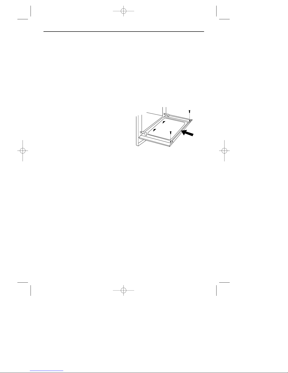
3.Door glass panel(s)
a.Open the door and insert 2 screws
through the inner holes in the door
hinge arms (to stop the door from
springing up when you remove the
outer glass panel).
b.Slide out the inner glass panel.
I
MPORTANT: The inner glass panel must
be replaced the right way up as shown
(so the reflective side faces inwards)
and also pushed fully into the stop
position.
c. Hold the door handle as you
unscrew the 2 corner screws
through the door frame as shown.
d.Remove the outer glass panel by
carefully pulling towards you.
4.Oven light bulb(s)
a.Remove the oven shelves.
b. Grasp the back edge of the light
cover and pull forward.
c. Unscrew the bulb.
SERVICING INSTRUCTIONS
SLIDE
IN
SLIDE
IN
THIS SIDE UP
33
18291 01 04/11/2002 12:19 Page 35
Page 36
5.Grill glass
a. Remove the grill cowl and burner
(11).
b.Lift up all the tabs which secure the
grill glass.
c. Replace the glass and bend the
securing tabs back down.
6.Main oven burner / electrode
/ injector
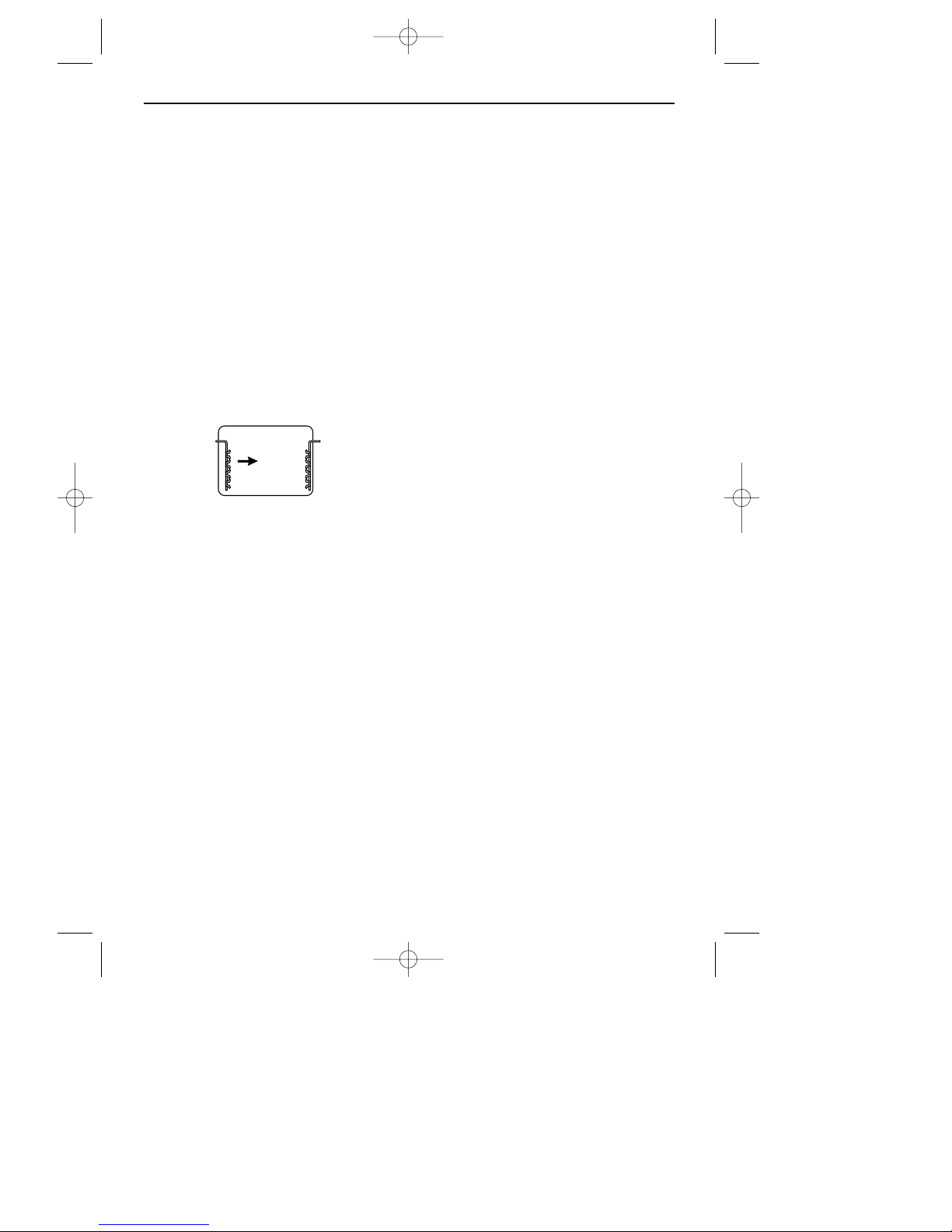
a.It is easier to list out the false oven
back is you first remove the oven
shelf runners.
Grasp the runners and slide out of
the hanging holes as shown.
b.From inside the oven unscrew the 3
screws which secure the false oven
back to the back of the oven.
c. Pull off the lead from the electrode
at the left-hand end of the burner.
d.Ease up the clip to release the FSD
probe.
e. From inside the oven, unscrew the 2
‘partially hidden’ screws from the
lower front edge of the oven burner
bracket.
f. Hold the right-hand side of the
burner, lift up and move to the right,
pull forward to clear the injector.
7.FSD valve (main oven)
a.Remove appliance from housing (2).
b.Looking from the front, unscrew the
left-hand side panel securing screws
and lift clear.
c. Disconnect the inlet from the FSD
valve, and the probe from the
burner clip.
d.Lift up the valve (complete with
injector) and slide it out from the
oven burner.
8.Top oven burner / electrode /
injector.
a.From inside the oven remove the
oven burner shield by slackening
the single screw through the hole in
the front of the shield, slide forward
and lift off.
b.Pull off the lead from the electrode
at the LH end of the burner.
c. Ease up the clip to release the FSD
probe.
d.Lift up the left-hand side of the
burner then clear the right, and slide
to the left to clear the injector.
Note: When replacing an oven
burner, locate the pegs into the slots
then push the right side down first.
SERVICING INSTRUCTIONS
34
18291 01 04/11/2002 12:19 Page 36
Page 37
9.FSD valve (top oven)
a.Remove appliance from housing (2).
b.Looking from the front, unscrew the
right-hand side panel securing
screws and lift the panel clear.
c. From inside the oven, remove the
oven burner (6).
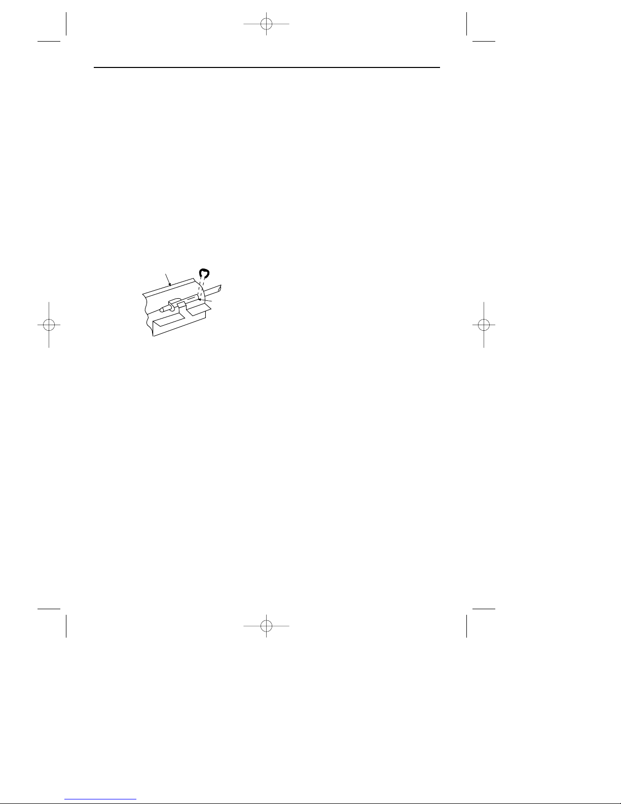
d.Pull off the injector carrier position-
ing clip at the right-hand side of the
oven burner bracket (as shown).
e. Disconnect the inlet from the FSD
valve, this can now be removed,
complete with the injector carrier
and probe.
10. Grill injector
a.Remove appliance from housing (2).
b.Unscrew the top panel and rear
panel securing screws and lift the
panels clear.
c. The grill injector is in the aluminium
manifold block.
d.To gain access to the 4 screws
underneath the manifold block, the
logic control pcb can be released
by squeezing in the plastic heads of
the plastic mounting posts.
e. Disconnect the grill supply pipe from
the side of the manifold block.
f. Unscrew the 4 screws from under-
neath the manifold block.
g.Ease the manifold block off the grill
pipe, and lift clear.
h. The injector can now be removed
using a 4BA tube spanner.
11. Grill burner
a.Remove appliance from housing (2).
b.Unscrew the top panel and left-hand
side panel securing screws and lift
the panels clear.
c. Pull off the grill electrode lead.
d.Unscrew the 4 screws (2 each side)
which secure the grill cowl.
e. Unscrew the 4 screws which secure
the burner to the grill cowl.
f. The cowl can now be removed by
sliding to one side.
g.Lift the burner slightly and ease
forward to disengage the pipe from
the manifold.
N
OTE: When replacing the grill burner,
make sure the burner mixing tube is
pushed fully into the manifold block,
and the 2 side lugs on the surrounding
plate come onto the top of the grill
burner, not pushed down under the
grill burner.
12. Grill electrode
a.Remove appliance from housing (2),
but only pull part way out, to gain
access to the screws which secure
the top (front) servicing panel.
b.Unscrew the top servicing panel
securing screws and lift the panel
clear.
c. Pull off the electrode lead.
SERVICING INSTRUCTIONS
Oven burner
bracket
Injector carrier
positioning clip
Groove
35
18291 01 04/11/2002 12:19 Page 37
Page 38

13. Double solenoid valve
a.Remove appliance from housing (2).
b.Unscrew the top panel, back panel,
and right -hand securing screws and
lift the panels clear.
c. Disconnect the valve leads from its
terminal block and feed through the
grommet.
N
OTE: When replacing the valve, the
leads must be fed through the
grommet.
d. Disconnect the bundy tubing from
the inlet and outlet to the valve.
14. Light switch / neon light(s)
a.Remove the outer frame trim.
b.Remove the facia glass panel (1).
c. Release the appliance from housing
(2), but only pull forward slightly to
gain access to the 2 screws which
go through the top panel and into
the back of the metal facia.
d.Remove the metal facia securing
screws and pull forward slightly.
e. Pull off the leads from the back of
the switch.
f. Light switch
- squeeze in the retaining tabs and push the switch out
through the front of the facia.
g.Neon light
- squeeze in the retaining
tabs and pull the light out from the
back of the facia.
15. Logic control pcb
a.Remove appliance from housing (2).
b.Unscrew the top panel and back
panel securing screws and lift the
panel clear.
c. Make a note of the connections and
disconnect the leads from the pcb.
d.Squeeze in he plastic heads of the
mounting posts to release the pcb.
e. When re-connecting the leads to the
new pcb, refer to the wiring
diagram.
16. Thermostat(s)
a.Remove the outer frame trim.
b.Remove appliance from housing (2).
c. Unscrew the top panel and right-
hand side panel securing screws
and lift the panels clear.
d.Remove the facia glass panel (1).
N
OTE: When assembling, it is easier to
replace the facia glass panel first then
the outer frame trim.
e. Remove the indicator discs and
bezels.
f. From inside the oven unclip the
thermostat phial from the front of the
oven roof and feed out through the
hole in the oven roof.
g.Disconnect the tubing connections
from the rear of the stat / tap.
h. Unscrew the metal facia securing
screws and pull the facia forward
slightly to clear the spindle.
i. Disconnect the stat from the tap rail.
SERVICING INSTRUCTIONS
36
18291 01 04/11/2002 12:19 Page 38
Page 39

17. Cooling fan
a.Remove appliance from housing (2).
b.Unscrew the top panel and back
panel securing screws and lift the
panels clear.
c. Disconnect the fan leads from its
terminal block and note the position
of the leads in relation to the
mounting bracket.
d.Unscrew the 4 screws which secure
the fan mounting bracket to the
oven back.
e. Remove the 4 screw which secure
the fan to the mounting bracket.
18. Door switch(es)
Note: Looking at the front of the
appliance, the main oven door switch
is behind the left-hand side panel and
the top oven / grill switch is behind the
right-hand side panel.
a.Remove appliance from housing (2).
b.Unscrew the top panel and side
panel securing screws and lift the
panels clear.
c. Unscrew the screws which secure
the door switch and its bracket to
the oven frame.
19. Thermal cutout
a.Remove appliance from housing (2),
and only pull part way out, to again
access to the screws which secure
the top (front) servicing panel.
b.Unscrew the top servicing panel
securing screws and lift the panel
clear.
c. From the back of the metal facia,
pull off the 2 leads from the cutout
and unscrew its 2 securing screws.
20. Pressure switch
a.Remove appliance from housing (2).
b.Unscrew the top panel and back
panel securing screws and lift the
panels clear.
c. The pressure switch is secured to the
back panel by 2 screws.
d.Disconnect the tubing and electrical
connections and attach to the new
switch.
e. When re-connecting the tube, make
sure that it is connected to the termi-
nal marked L and the other end of
the tube goes through the hole in the
back panel by about 25 mm.
Ensure that the tube does not kink.
21. Ignition generator
a.Remove appliance from housing (2).
b.Unscrew the top panel and back
panel securing screws and lift the
panels clear.
c. The ignition generator is attached
by screws to the oven back.
d.Disconnect the leads.
e. Re-connect the leads to the new
ignition generator.
SERVICING INSTRUCTIONS
37
18291 01 04/11/2002 12:19 Page 39
Page 40

22. Oven light fitting(s)
a.Remove appliance from housing (2).
b.Unscrew the top panel and side
panel securing screws and lift the
panels clear.
c. From inside the oven grasp the back
edge of the light cover and pull
forward.
d.Remove the leads from the back of
the light fitting.
e. Squeeze in the metal retaining clips
to release the fitting from the oven
side.
23. Oven and grill microswitch(es)
a.Remove facia glass panel (1).
b.Take off the indicator bezel.
c. Disconnect the leads from the micro-
switch.
d.Unscrew the screws which secure
the micro-switch to the metal facia.
24. Convection fan
a.Remove appliance from housing (2).
b.Unscrew the top panel and back
panel securing screws and lift the
panels clear.
c. From inside the oven unscrew the 3
screws which secure the loose oven
back.
d.Unscrew the 4 screws which secure
the fan cover.
e. Unscrew the nut from the centre of
the fan blades. (NB; left hand
thread).
f. From the back of the appliance, dis-
connect the fan leads and unscrew
the 3 fan securing screws.
25. Single solenoid valve
a.Remove appliance from housing (2).
b.Unscrew top, back, and left-hand
side panel securing screws, and lift
the panels clear.
c. Disconnect valve leads from termi-
nal block.
d. Disconnect bundy tubing from inlet
and outlet.
26. Fan timer relay board
a.Remove appliance from housing (2).
b.Unscrew the top panel and back
panel securing screws and lift the
panels clear.
c. Disconnect the leads from the relay
board.
d.Squeeze in the plastic heads of the
mounting posts to release the
board.
27. Programmer / clock
a.Remove facia glass panel (1).
b.Unscrew the programmer mounting
bracket securing screws.
c. Disconnect the leads from the back
of the programmer:
Digital clock:
To release the programmer, push in the plastic clips (one
each side) with a screwdriver.
Analogue clock:
Push in the steel clips
on the top and bottom edges.
NOTE: When re-connecting, please
refer to the wiring diagram.
SERVICING INSTRUCTIONS
38
18291 01 04/11/2002 12:19 Page 40
Page 41
28. Door frame
a.Remove appliance from housing (2).
b.The inner glass panel is not secured
to the frame and can be removed.
c. Unscrew the top panel and side
panel securing screws and lift clear.
d. Close the door and suppor t it with
one hand as you carefully unhook
the large springs from the door
hinge arms.
e. The door can now be removed.
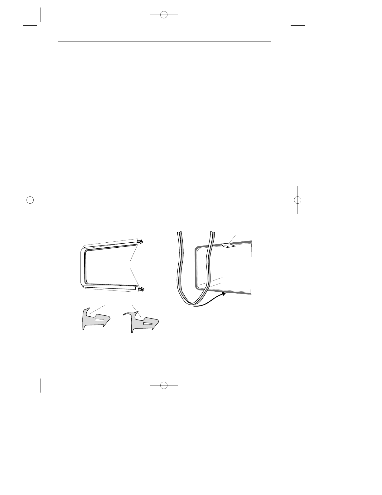
29. Door seal(s)
a.Pull of the old seal.
b. Slacken the screws in the stainless
steel flue cover at the front of the
oven / grill roof to ease insertion of
the seal.
c. Partly open the door to obtain best
access for the seal all around the
oven / grill.
d. Locate the middle of the new seal
and start to push into place at the
middle of the bottom edge of the
oven / grill cavity.
e. Make sure the narrow gap goes to
the inside, and locates onto the
oven cavity.
f. D
O NOT STRETCH the seal.
g.Make sure the seal is fitted correctly
as shown, and cut to fit.
i. Re-tighten the screws in the flue
cover.
SERVICING INSTRUCTIONS
narrow
gap
flue
cover
oven
cavity
Grill
seal
Oven
seal
narrow
gap
39
18291 01 04/11/2002 12:19 Page 41
Page 42

Data Badge Front frame
Pressure Setting 20 mbar
Pressure Test Point Inside of inlet block
Gas Category 1
2
H
Ignition 3 Outlet Re-ignition Generator
Oven / Grill Lights 25 W
Electrical Supply 230 - 240V 50Hz
GRILL
Burner Surface combustion behind ceramic glass
Spark Gaps 3 - 4 mm
Nominal Rate Qn 3.3 kW
Injector Amal Size 290
MAIN OVEN
Burner Bray type burner, sheet steel body, stainless
steel flame strip
Nominal Rate Qn 2.5 kW
Injector Amal size 180
TOP OVEN
Burner Bray type burner, sheet steel body, stainless
steel flame strip
Nominal Rate Qn 1.45 kW
Injector Amal size 100
Countries of Destination
GB Great Britain
IE Ireland
TECHNICAL DATA (Natural Gas)
40
18291 01 04/11/2002 12:19 Page 42
Page 43

TECHNICAL DATA (LP Gas)
Data Badge Front frame
Pressure Setting Propane 37 mbar
Butane 28 mbar
Pressure Test Point Inside of inlet block
Gas Category 1
3
+
Ignition 3 Outlet Re-ignition Generator
Oven / Grill Lights 25 W
Electrical Supply 230 - 240V 50Hz
GRILL
Burner Surface combustion behind ceramic glass
Spark Gaps 3 - 4 mm
Nominal Rate Qn 3.3 kW Propane 236 g/h
Butane 241 g/h
Injector Amal Size 110
MAIN OVEN
Burner Bray type burner, sheet steel body, stainless
steel flame strip
Nominal Rate Qn 2.5 kW Propane 179 g/h
Butane 182 g/h
Injector Amal size 75
TOP OVEN
Burner Bray type burner, sheet steel body, stainless
steel flame strip
Nominal Rate Qn 1.45 kW
Injector Amal size 40
Countries of Destination
GB Great Britain
IE Ireland
41
18291 01 04/11/2002 12:19 Page 43
Page 44

18291 01 04/11/2002 12:19 Page 44
Page 45

18291 01 04/11/2002 12:19 Page 45
Page 46

18291 01 04/11/2002 12:19 Page 46
 Loading...