

Page 1

S1100 Professional
Cooker Hood
User & Installation Instructions
Page 2

Page 3

User’s Section . . . . . . . . . . . . . . . . . . . . . . . . . . . . . . . . . . . . . . . . . 2
Introduction . . . . . . . . . . . . . . . . . . . . . . . . . . . . . . . . . . . . . . . . . . . . . . . . . 2
Using the Hood . . . . . . . . . . . . . . . . . . . . . . . . . . . . . . . . . . . . . . . . . . . . . . 3
Care and Maintenance . . . . . . . . . . . . . . . . . . . . . . . . . . . . . . . . . . . . . . . . . 4
Installation . . . . . . . . . . . . . . . . . . . . . . . . . . . . . . . . . . . . . . . . . . . 6
Regulations and standards . . . . . . . . . . . . . . . . . . . . . . . . . . . . . . . . . . . . . . . 6
Ventilation requirements. . . . . . . . . . . . . . . . . . . . . . . . . . . . . . . . . . . . . . . . . 6
Mounting height . . . . . . . . . . . . . . . . . . . . . . . . . . . . . . . . . . . . . . . . . . . . . . 6
Wall fixing. . . . . . . . . . . . . . . . . . . . . . . . . . . . . . . . . . . . . . . . . . . . . . . . . . 7
Method 1: Re-circulation . . . . . . . . . . . . . . . . . . . . . . . . . . . . . . . . . . . . . . . . 9
Method 2: Extraction through an outside wall . . . . . . . . . . . . . . . . . . . . . . . . 10
Electrical connection . . . . . . . . . . . . . . . . . . . . . . . . . . . . . . . . . . . . . . . . . . 11
Technical Data . . . . . . . . . . . . . . . . . . . . . . . . . . . . . . . . . . . . . . . 12
Customer Support . . . . . . . . . . . . . . . . . . . . . . . . . . . . . . . . . . . . . 13
Please read this handbook carefully and keep it for future reference.
1
Contents
Page 4

Thank you for buying this high quality
hood from Stoves, we hope it makes and
attarctive and useful addition to your
kitchen.
Our policy is one of constant development
and improvement. Strict accuracy of
illustrations and specifications is not
guaranteed. Modification to design
and materials may be necessary
subsequent to publication.
Before using the appliance for the
first time, remove all packaging and
protective polythene film.
Your first year Guarantee
To fulfil the conditions of your guarantee,
this appliance must be correctly
installed and operated, in accordance
with these instructions, and only be
used for normal domestic purposes.
Please refer to your guarantee card for
further details.
Please note that the guarantee, and
Service availability, only apply to the
UK and Republic of Ireland.
Installation
This appliance has been designed for
use as an exhausting (air evacuation
to the outside) or filtering (indoor air
re-cycling) hood.
Note: This appliance does not come
supplied with a ducting kit, or carbon
filters. Details for ordering these parts
are at the back of the handbook.
Because of the complexity and weight
of the appliance, it is recommended
that the installation be carried out by
specialist personnel.
The manufacturer declines all responsibility
for damage caused by improper or
unworkmanlike installation.
Please read this handbook carefully
and keep it for future reference.
2
Introduction
Page 5

To illuminate the cooking area underneath the hood, push the light control
button in to the “on” position. To
switch off, press again to return to the
“off” position.
To operate the hood, press the button
for the required speed - select: 1 low,
2 medium, or 3 high speed. The
neon indicator light will light up to
show when the fan is operating. To
switch off, press the “off” button.
Important safety notes
• Keep hob rings covered with pans
when switched on to avoid damaging the hood. The use of an
unprotected flame can cause a fire
hazard.
•
Do not flambé food underneath
the hood.
• When frying foods, take care to
avoid cooking oil flares.
• Wash the grease filters regularly refer to the cleaning section.
•
Do not check filters while the hood
is in use.
•
Do not touch the lamps after
prolonged use of the appliance.
Re-circulation method only:
• Keep the air ducting vents clear of
obstruction.
• Change the carbon filters every 4
months.
3
Using the Hood
Figure 1
0
1
2 3
A B C ED
F
T
Figure 1: hood controls:
The controls work as follows:
A - Neon light
B - Off
C - Position 1
D - Position 2
E - Position 3
F - Automatic stop timer
Booster function
This hood also has a booster function.
To activate the booster, press button E
while the hood is in use and it will
increase speed for 20 seconds, before
slowing down again.
We recommend that you switch on the
hood for a few minutes before you
start cooking, and then leave it running
for approximately 15 minutes afterwards to ensure that all odours are
extracted.
Page 6

Before cleaning or maintenance,
switch off the electricity supply.
Replacing a light bulb
1. Switch off the electricity supply.
2. Remove the lamp cover by turning
it anticlockwise.
3. Remove the light bulb - by moving
it in the direction of the arrow.
4. Replace it with a new halogen
light bulb (taking care to avoid
skin contact with the bulb glass).
5. Replace the lamp cover, turning
clockwise to secure.
Outer casing
All external parts of the outer casing
can be safely cleaned with a c l e a n
cloth wrung out in hot soapy water.
Do not use caustic pastes, abrasive
cleaning powders, wire wool, hard
implements, or any products containing
chlorides as they will damage the
surfaces.
Stubborn marks can be removed using
a stainless steel cleaner. We recommend that you clean the whole of the
stainless steel area to maintain a uniform finish.
Sharp objects can mark the surface of
stainless steel, but marks will become
less noticeable with time.
To maintain the finish of the stainless
steel, or to remove any greasy marks,
wipe the stainless steel surface sparingly
with a
minimum amount of Baby Oil
and kitchen paper.
Do not use cooking oils, as these may
contain salt, which can damage the
stainless steel surface.
4
Care & Cleaning
Page 7
Before cleaning or maintenance,
switch off the electricity supply.
To avoid any fire risk, the following
cleaning instructions must be followed:
Grease filters
The grease filters absorb grease and
dust from cooking fumes, which would
otherwise damage the inside of the hood.
The grease filters should be removed
and cleaned regularly - with normal
use, this should be every 2 months.
To clean use warm soapy water, or
wash in a dishwasher. The grease filters may slightly change coloyr follwing washing, however this does not
affect their performance.
I m p o r t a n t : Frequent washing is
essential to prevent a build up of
grease in the filters which could
become a fire hazard.
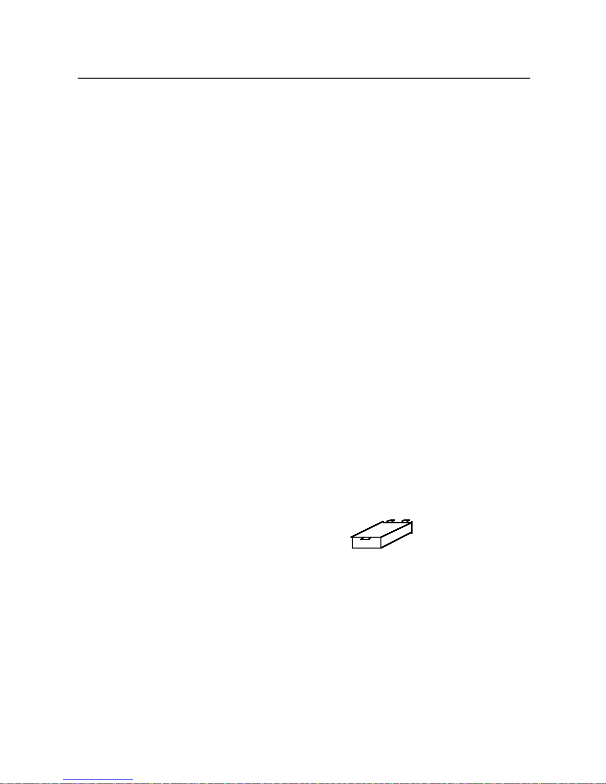
1. Remove the filters from the hood.
2. Carefully wash the grease filters in
hot soapy water and dry with a
clean towel.
3. Refit the clean filters.
Carbon filters (models installed for
use with the re-circulation method only)
The carbon filters absorb cooking
odours and need renewing after about
4 months of normal use. Replacement
carbon filters can be obtained from
your supplier.
Saturation of the activated charcoal in
the filter will depend on how often the
hood is used, the type of kitchen and
the regularity of cleaning the grease filter.
The carbon filters cannot be
washed - renew every 4 months.
1. Remove the grease filters from the
hood.
2. Remove the old carbon filter
pressing in the release catch on
the right hand side of the filter, pull
the filter out.
3. Fit the new carbon filter by engaging
it into the slots below the motor,
push in firmly .
4. Refit the grease filters.
5
Care & Cleaning
carbon filters
Page 8

Regulations and standards
Before you start please read instructions
carefully. All installations, service and
repair work must be in accordance
with local standards and regulations.
In the UK the regulations and standards
are as follows:-
1. Building regulations.
2. The current I.E.E. wiring regulations.
3. Electricity at work regulations 1989.
4. Installation and servicing instructions
for this appliance.
Ventilation
Adequate ventilation, in accordance
with the Gas Safety Regulations 1996
(Installation and Use), and the relevant
building regulations must be provided
when the hood extracts air from a
room with a flued gas burning
appliance, which is not of the
“balanced flue” type.
Mounting height
The cooker hood must be fitted at least
650 mm above a gas or electric hob.
If cooker / hob instructions give a
different figure to that given above,
then the higher measurement should
be followed.
To prevent possible hood cut-out, a
clearance of 750 mm is recommended
above gas hobs where possible.
Select method of operation
The cooker hood has two possible
methods of operation:
Method 1: Re-circulation.
Installation with dual filtration to clean
the air before it is re-circulated into the
room.
Method 2: Extraction through an
outside wall.
The hood can be installed with a duct
to extract cooking fumes through an
outside wall.
Please ensure you order the correct
parts for the operation you wish to
use.
Dimensions
Please note that all dimensions and
sizes are nominal, some variation is to
be expected.
6
Installation
Page 9
Installation
7
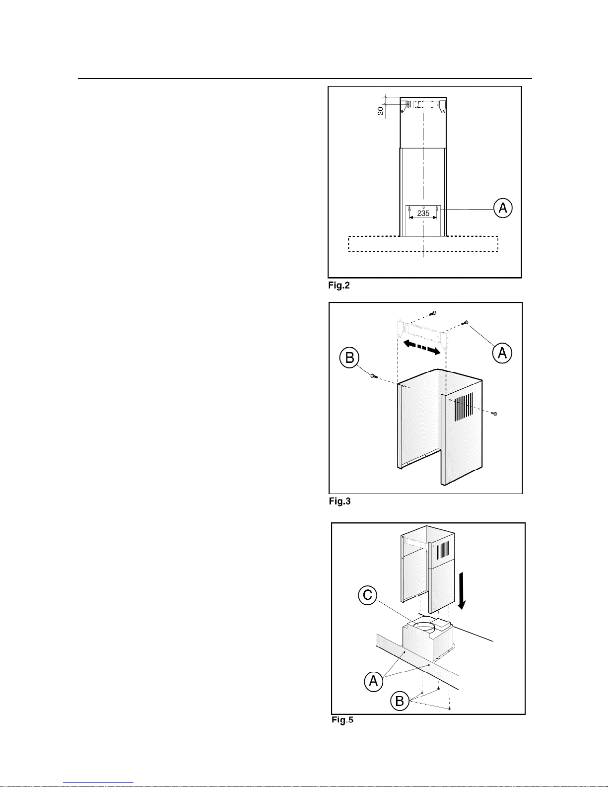
Wall fixing (fig 2,3 & 5)
1. Using the screws provided, fit the
two wall brackets to the support
bracket so that the distance
between the outer edges of the 2
wall brackets is the same as the
width of the upper link section.
2. Drill holes A (fig 2) for fixing hood
and wall bracket to wall.
3. Use screws and screw anchors
suitable for the type of wall
(eg; concrete, plasterboard, etc).
Fasten wall brackets to the wall.
Hang the hood on the wall using
holes A fig 5.
4. Complete fastening the hood to
the wall using holes B & D.
Securing the telescopic flue.
• Make sure the the power cables
are inside the decorative flue to
conceal them.
• Make sure there is an exhaust
opening prepared.
• Adjust the width of the support
bracket (fig 3), then fix it into the
ceiling using the screws shown in
fig 3 - A. This should be as shown
in fig 3.
• In some cases it may be necessary
to adjust the length of one or both
of the chimney sections. Cut the
bottom of each section so that the
cut is hidden using suitable cutting
implements. Please take care not
to obstruct the ducting vents.
Page 10
900 or
1000mm
Installation
8
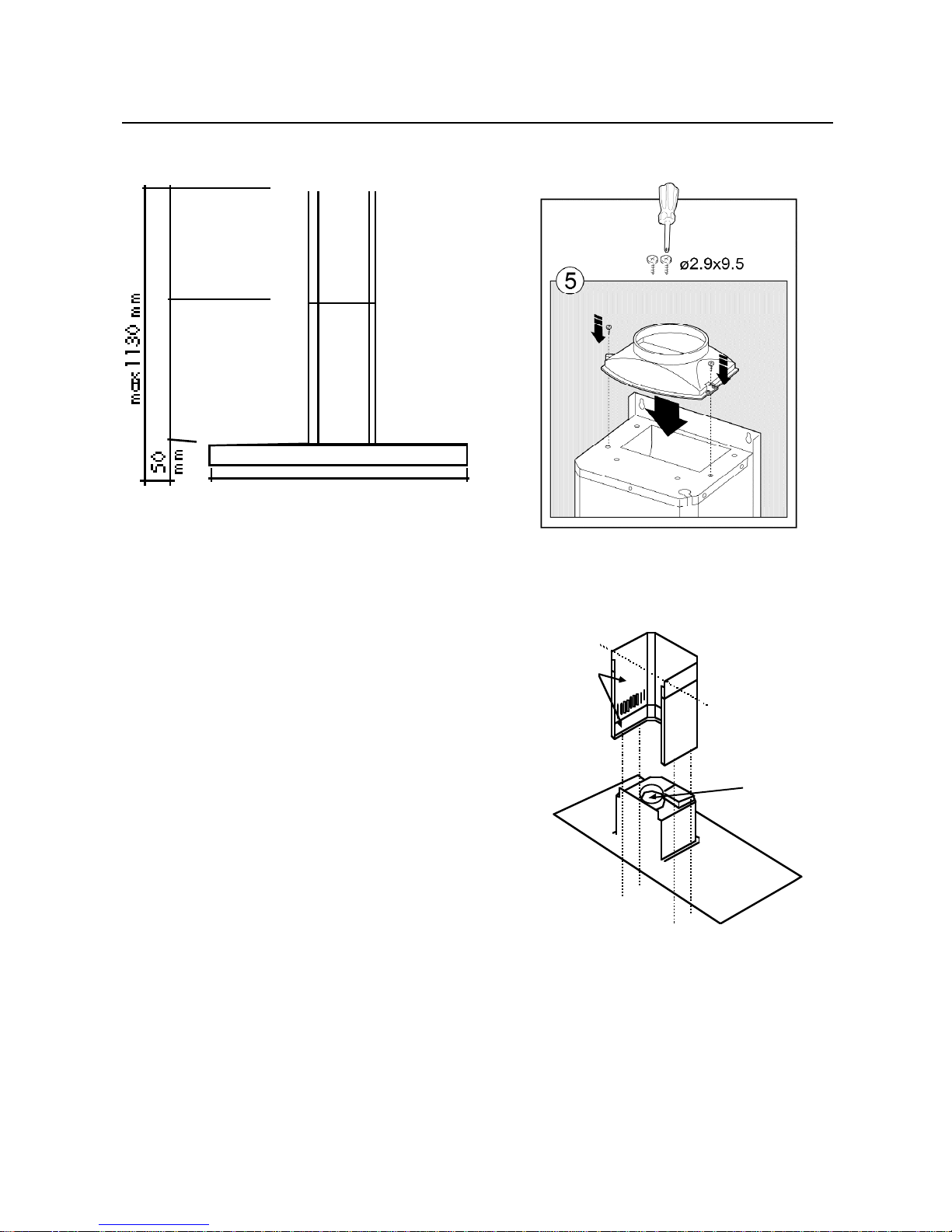
Please note: Dimensions are nominal
and shown here as maximums.
Body of hood dimensions:
900 Professional
900mm x 520mm x 50mm
in W x D x H
1000 Professional
1100mm x 520mm x 50mm
in W x D x H
Chimney height (inc. hood body)
285mm x 256mm x 665 - 1130mm
in W x D x H
link
pieces
secure to
wall brackets
with screws
connection
flange
Figure 4 Figure 5
Figure 6
Page 11

Method 1: Re-circulation (dual
filtration)
The fan draws cooking fumes through
the washable grease filters into the
underside of the hood, then through
the carbon filters, to remove odours
before returning clean air to the
kitchen via the air ducting vents.
When selecting the best position for
the hood, ensure that air flow from the
air ducting vents is not obstructed by
cupboards, shelves, etc.
Do not vent into enclosed cupboard
space. See figures 5 & 6.
Assembly
1. Remove the grease filters.
2. Fit the new carbon filter (if supplied
- may be packed separately) b y
e n g a g i n g it into the slots below the
motor, push in firmly.
3. Fit and secure the air-flow diverter
to the support bracket using the
screws provided.
4. Insert the clip-in flange onto the airflow diverter.
5. Using a 120 mm internal diameter
link pipe, attach the connection
flange to the clip-in flange.
6. Insert the upper link section inside
the lower link section with the slots
turned upwards.
7. Secure the lower link section to the
hood using the screws provided.
8. Move the upper link section down
as far as the wall brackets and
secure.
9. Air re-circulates into the room
through the slots in the upper link
section. Take care to ensure that
these side air ducting vents are not
blocked or obstructed.
9
Installation
Page 12

Method 2: Extraction through
an outside wall
The fan draws cooking fumes through
the washable grease filter into the
underside of the hood, then the fumes
are expelled through a duct or directly
through an outside wall.
Refer to figures 5 & 6.
Assembly
1. Remove the grease filters.
2. Remove the carbon filters (if
supplied) and discard, as this is
not required when installing the
cooker hood as an extractor fan.
3. Secure the connection flange.
4. Using a 120 mm internal diameter
link pipe, attach connection flange
to the outside vent.
5. Insert the upper link section inside
the lower link section with the slots
turned downwards.
6. Secure the lower link section to the
hood using the screws provided.
7. Move the upper link section down
as far as the wall brackets and
secure with the screws provided.
Wall vent kit and ducting
• For connecting the hood outlet
adaptor to the outside wall, we
recommend that a wall vent kit is
purchased from your supplier or
local hardware store.
• Use a 125 mm diameter ducting
kit and connect to the ducting
outlet adaptor.
• Horizontal duct runs should be
avoided. A slope of 5˚ or more
upwards from the hood to the wall
outlet will assist the flow of air.
• The ducting pipe and any connecting
pieces should be coupled to the
preceding piece by pushing into
and never over it - the upper part
must be fitted over the lower part.
• The outlet from the hood must not
be ducted into a wall cavity,
through a ventilator shaft or
through a chimney. It must not be
ducted through a flue used by a
non-electrically powered appliance.
• Adequate ventilation must be
provided if a cooker hood extracts
fumes from the room at the same
time as an appliance powered by
a fuel other than electricity (such
as a gas appliance) is operated.
The extractor hood removes air
from the room which the burner is
dependant on for combustion.
10
Installation
Page 13
Installation
Electrical connection
This appliance is double insulated for
safety and therefore does not require
an earth connection to the mains inlet.
The wires in the mains lead are
coloured in accordance with the
following code:
Blue = neutral, Brown = live.
As the colours of the wires in the
mains lead for the appliance may not
correspond with the coloured markings
identifying the terminals in your spur
box, proceed as follows:
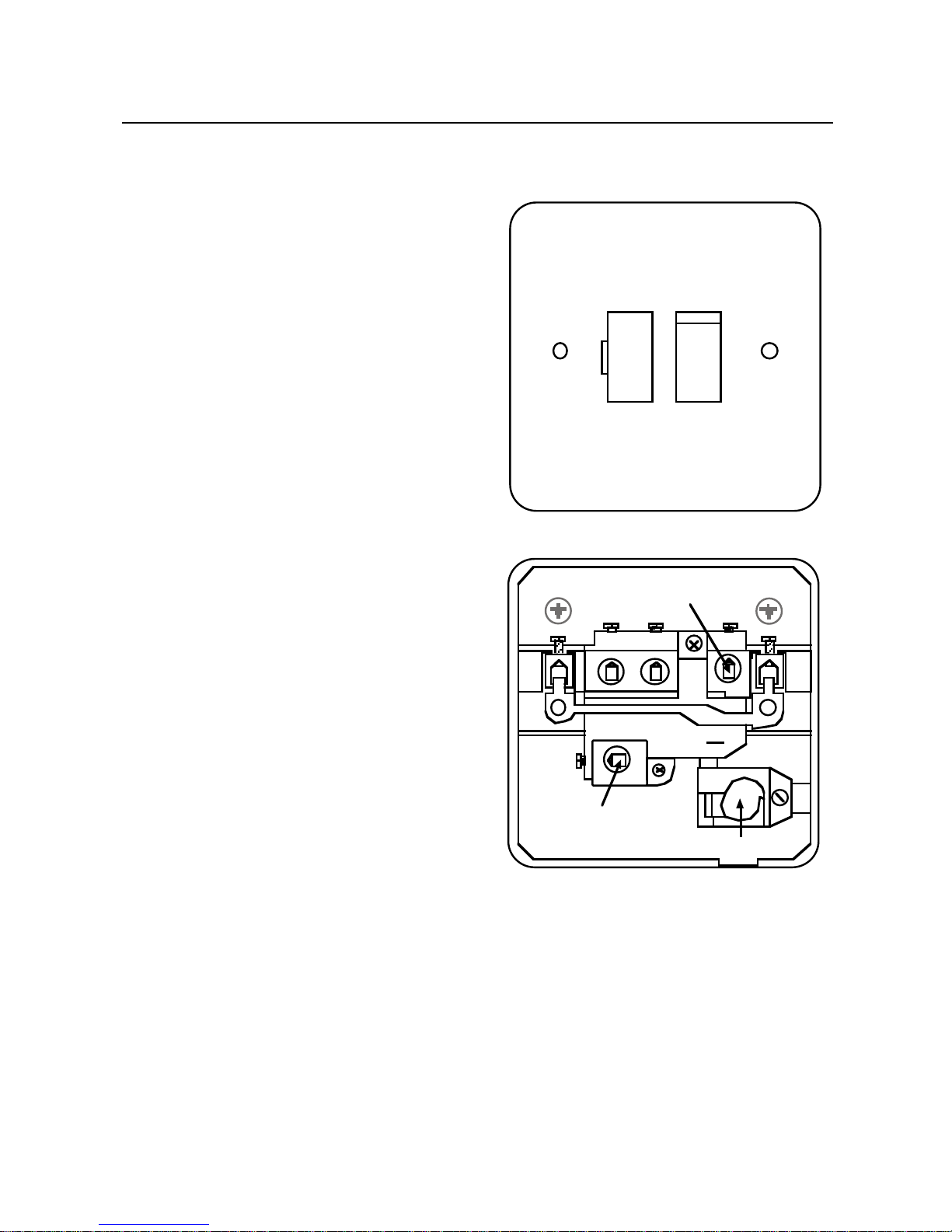
1. The wire which is coloured blue
must be connected to the terminal
marked N (neutral)
L O A D
, or
coloured black.
2. The wire which is coloured brown
must be connected to the terminal
marked L (live)
LOAD
, or coloured
red.
The fused spur socket should be
positioned where is is easily accessible
so you can switch off the supply to the
hood when renewing the light bulb.
Figure 7: Typical example of a
double pole fused spur outlet.
11
ON
FUSE
Use a 3 amp fuse
Typical example of a double
pole fused spur outlet
N L
SUPPLY LOAD
L
~
N
LOAD
13
250
Neutral
Live
Cable
Page 14

12
Technical Data
Electricity supply
230 - 240V ~ 50Hz
Classification
class II metal encased
Noise level (External Venting)
Position 4 (booster) 55 dBA
Position 3 51 dBA
Position 2 43 dBA
Position 1 41 dBA
Noise Level (Internal Venting)
Position 4 (booster) 56 dBA
Position 3 53 dBA
Position 2 44 dBA
Position 1 34 dBA
Light bulbs
2 x 20W halogen
Please make sure you follow the
instructions for replacing light bulbs
carefully and always make sure you
use the correct bulb type.
Motor rating
250W
Carbon filters
x 2 - available as Spares
Grease filters
x 3 aluminium panel
Note:
After cleaning, grease filters may lose
their colour slightly - this does not
affect their performance.
Extraction Rate (External)
Position 4 (booster) 650m3/H
Position 3 564m3/H
Position 2 408m3/H
Position 1 253m3/H
Extraction Rate (Internal)
Position 4 (booster) 554m3/H
Position 3 490m3/H
Position 2 356m3/H
Position 1 225m3/H
Page 15
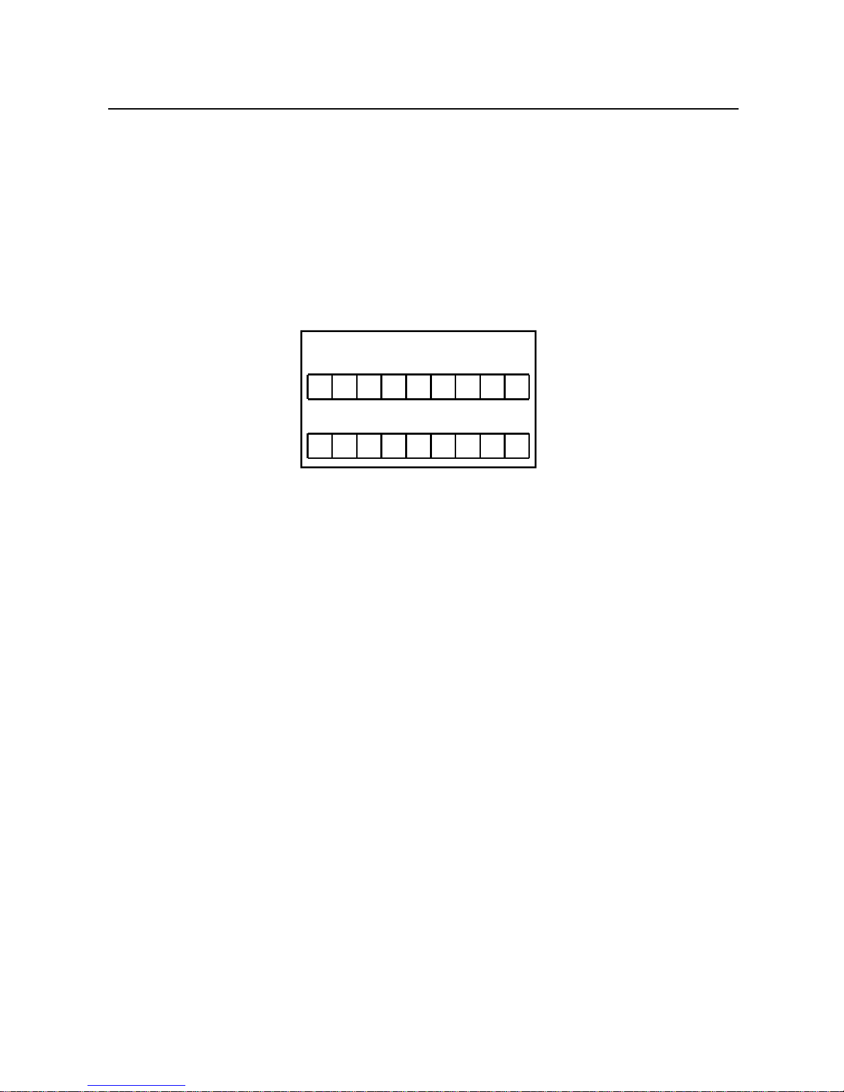
Model No
Serial No
Customer Support
In case of difficulty please call our Customer Support Helpline on
0844 815 3740
When you dial this number you will hear a ringing tone. This indicates that your
call has been accepted and is being held in a queue. Calls are answered in strict
rotation as our Customer Support Representatives become available.
Enter appliance numbers here for future reference:
Please ensure you have the above details (Model No and Serial No) to hand
when calling Customer Support - they are essential to booking your call.
Spare Parts available for this product:
Carbon filters: 082612620
1 metre ducting kit: 082611309
3 metre ducting kit: 082611310
13
Page 16

STONEY LANE, PRESCOT, MERSEYSIDE, L35 2XW
08 27234 01 © 09.2011
3LIK1005
 Loading...