

Page 1
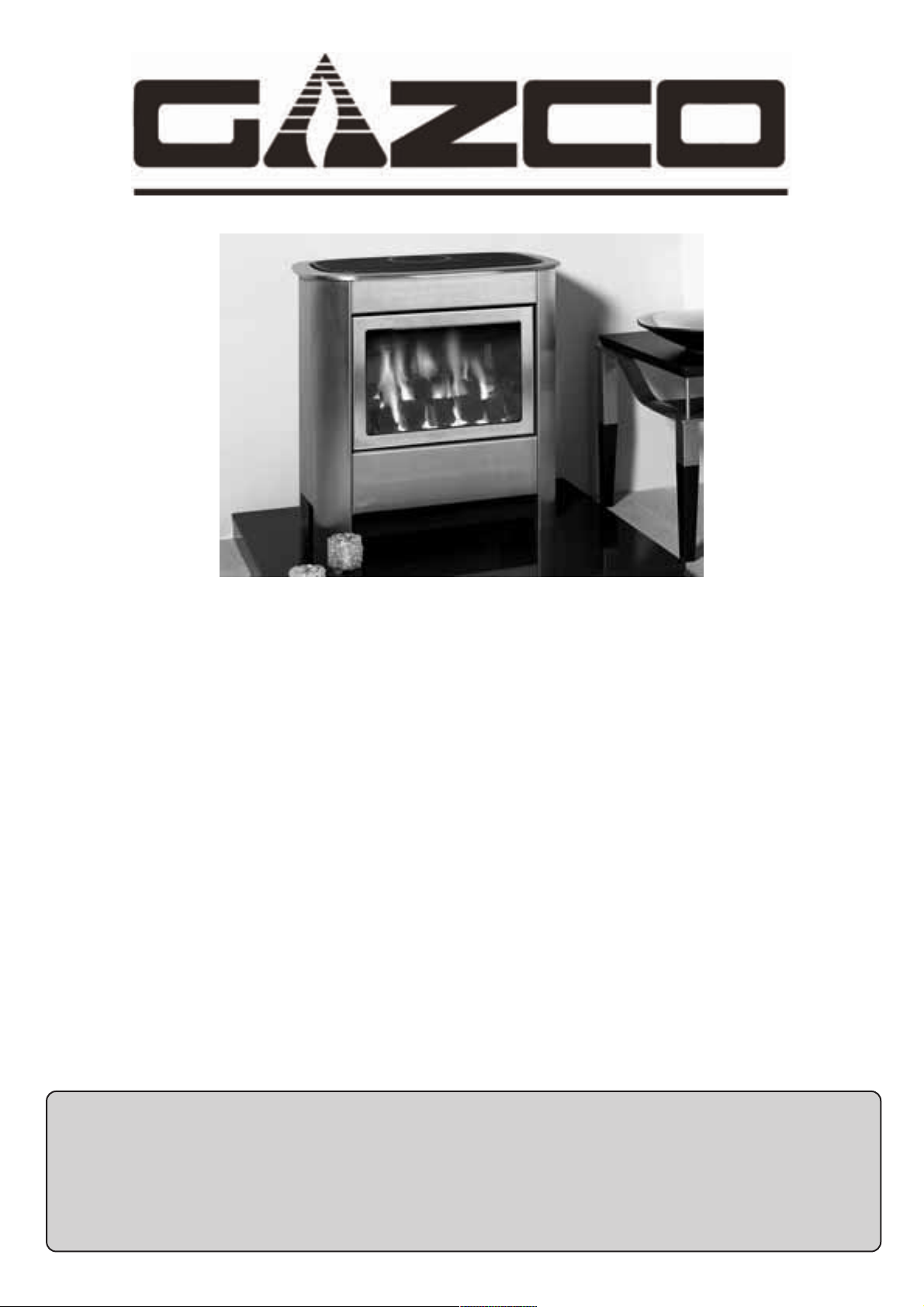
Steel Manhattan
Coal Effect Stove Range
Conventional Flue
With upgradeable control valve
Instructions for Use,
Installation and Servicing
For use in GB, IE (Great Britain and Eire)
PR0617 Issue 4 (February 2007))
IMPORTANT
Do not attempt to burn rubbish in this fire. This stove must only be operated with the door secured firmly in position.
The outer casing of this stove will become hot whilst in operation, it is therefore recommended that the appliance be
guarded to protect the young and infirm using a suitable guard.
Ensure that fabrics such as curtains are not positioned above or near to the stoves outer casing.
Please read these Instructions carefully and keep them in a safe place.
They will be needed when servicing the fire.
The commissioning sheet found on page 3 should be completed by the installer.
This appliance has been certified for use in countries other than those stated. To install this appliance in these countries, it is essential to obtain the
translated instructions and in some cases the appliance will require modification. Contact Gazco for further information.
Page 2

2
CONTENTS
COVERING THE FOLLOWING MODELS
MANHATTAN - 8619 - P8619
PAGE
APPLIANCE COMMISSIONING CHECKLIST 3
USER INSTRUCTIONS 4
INSTALLATION INSTRUCTIONS 8
Technical Specifications 8
Site Requirements 9
Installation 10
Commissioning 14
SERVICING INSTRUCTIONS 15
Servicing Requirements 15
Fault Finding 15
How to replace parts 17
Basic spare parts list 22
Service records 23
Page 3
3
APPLIANCE COMMISSIONING CHECKLIST
Dealer. . . . . . . . . . . . . . . . . . . . . . . . . . . . . . . . . . . . . . . . . . . . . . . . . . . . . . . . . . . . . . . . . . . . . . .
. . . . . . . . . . . . . . . . . . . . . . . . . . . . . . . . . . . . . . . . . . . . . . . . . . . . . . . . . . . . . . . . . . . . . . . . . . . . . . . .
. . . . . . . . . . . . . . . . . . . . . . . . . . . . . . . . . . . . . . . . . . . . . . . . . . . . . . . . . . . . . . . . . . . . . . . . . . . . . . . .
Contact No. . . . . . . . . . . . . . . . . . . . . . . . . . . . . . . . . . . . . . . . . . . . . . . . . . . . . . . . . . . . . . . .
Date of Purchase. . . . . . . . . . . . . . . . . . . . . . . . . . . . . . . . . . . . . . . . . . . . . . . . . . . . . . . .
Model No. . . . . . . . . . . . . . . . . . . . . . . . . . . . . . . . . . . . . . . . . . . . . . . . . . . . . . . . . . . . . . . . . .
Serial No. . . . . . . . . . . . . . . . . . . . . . . . . . . . . . . . . . . . . . . . . . . . . . . . . . . . . . . . . . . . . . . . . . .
Gas Type . . . . . . . . . . . . . . . . . . . . . . . . . . . . . . . . . . . . . . . . . . . . . . . . . . . . . . . . . . . . . . . . . . .
Installation Company. . . . . . . . . . . . . . . . . . . . . . . . . . . . . . . . . . . . . . . . . . . . . . . . . .
. . . . . . . . . . . . . . . . . . . . . . . . . . . . . . . . . . . . . . . . . . . . . . . . . . . . . . . . . . . . . . . . . . . . . . . . . . . . . . . . .
. . . . . . . . . . . . . . . . . . . . . . . . . . . . . . . . . . . . . . . . . . . . . . . . . . . . . . . . . . . . . . . . . . . . . . . . . . . . . . . . .
Engineer . . . . . . . . . . . . . . . . . . . . . . . . . . . . . . . . . . . . . . . . . . . . . . . . . . . . . . . . . . . . . . . . . . . .
Contact No.. . . . . . . . . . . . . . . . . . . . . . . . . . . . . . . . . . . . . . . . . . . . . . . . . . . . . . . . . . . . . . . .
Corgi Reg No.. . . . . . . . . . . . . . . . . . . . . . . . . . . . . . . . . . . . . . . . . . . . . . . . . . . . . . . . . . . . .
Date of Installation . . . . . . . . . . . . . . . . . . . . . . . . . . . . . . . . . . . . . . . . . . . . . . . . . . . . .
IMPORTANT NOTICE
Explain the operation of the appliance to the end user, hand the completed instructions to them for safe keeping,
as the information will be required when making any guaranteed claims.
DEALER AND INSTALLER INFORMATION
FLUE CHECK PASS FAIL
1. Flue is correct for appliance
2. Flue flow test
3. Spillage test
GAS CHECK
1. Gas soundness & let by test (Please circle Y / N as appropriate) Y / N Y / N
2. Standing pressure test in figures (e.g. 20 mb) mb
3. Appliance working pressure (on High Setting) in figures (e.g. 20 mb) mb
NB All other gas appliances must be operating on full
4. Gas rate m3/h
5. Does ventilation meet appliance requirements
6. Have controls been upgraded (Upgradeable models only) 8455 Standard YES NO
8456 Programmable Time & Temperature YES NO
This product is guaranteed for 2 years from the date of installation, as set out in the terms and conditions of sale between Gazco and your
local Gazco dealer. This guarantee will be invalid, to the extent permitted by law, if the above Appliance Commissioning Checklist is
not fully completed by the installer and available for inspection by a Gazco engineer. The guarantee will only be valid during the
second year, to the extent permitted by law, if the annual service recommended in the Instructions for Use has been completed by a
Corgi registered engineer, and a copy of the service visit report is available for inspection by a Gazco engineer.
Page 4
1.12 In all correspondence, please quote the appliance type and
serial number which can be found on the databadge at the
rear of the stove.
1.13 This product is guaranteed for 2 years from the date of
installation, as set out in the terms and conditions of sale
between Gazco and your local Gazco dealer. Please consult
with your local Gazco dealer if you have any questions. In
all correspondence always quote the Model No. and Serial
No. Please ensure the commissioning checklist is completed
by your installer; this is a requirement of your Guarantee.
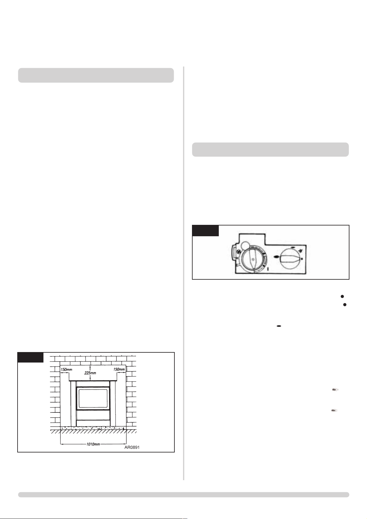
2.1 Locate the control valve on the appliance. There are two
control knobs on the valve:
- right controls the pilot ignition
- left controls the main burner.
2.2 If your appliance has already been upgraded to battery
remote control, please refer to the instructions provided
with the upgrade to operate the remote control. The
following instructions work for either situation.
2.3 Ensure that the left-hand control knob is pointing to off ( ).
2.4 Ensure that the right-hand control knob is pointing to off ( ).
2.5 Press in the right-hand control knob and, keeping he knob
depressed, turn it anti-clockwise until a click is heard and
the knob is pointing to pilot ( ). The pilot should now
light. If the pilot does not light, release the knob and repeat
the procedure until it does.
2.6 Keep the control knob pressed in for 10 seconds and then
release it, the pilot should stay alight. If the pilot goes out,
repeat the procedures until it remains lit.
2.7 If the pilot does not light after repeated attempts, contact
the retailer or installer from whom the appliance was
purchased.
2.8 Turn the right-hand control to point to main burner ( ).
The appliance can now be controlled using the left-hand
control knob.
2.9 Turn the left-hand control knob to point to low fire ( ),
the main burner lights on low. The burner can now be
controlled between low and high settings. Turn the control
knob anticlockwise to increase the flame height and
clockwise to decrease the flame height.
THE YELLOW FLAMES WILL APPEAR WHEN THE FIRE
HAS REACHED SUFFICIENT HEAT - TYPICALLY 10 TO 20
MINUTES.
IF THE APPLIANCE IS EXTINGUISHED OR GOES OUT IN
USE, WAIT 3 MINUTES BEFORE ATTEMPTING TO RELIGHT THE APPLIANCE.
4
USER INSTRUCTIONS
1.1 Installation and servicing must be carried out by a
competent person in accordance with Gas Safety
(Installation and Use) Regulations 1998, the relevant British
Standards for Installation, appropriate Codes of Practice and
in accordance with the manufacturers instructions. It is a
requirement that a CORGI registered engineer be used for
this purpose as they are approved by the HSE under the
above regulations.
1.2 This appliance is suitable for use in G.B. and I.E. using
Natural Gas at a supply pressure of 20mbar or LPG at a
supply pressure of 29mbar (Butane) or 37mbar (propane).
1.3 The installation shall also be completed in accordance with:
The Building Regulations issued by The Department of The
Environment.
The Building Standards (Scotland) Regulations issued by the
Scottish Development Department.
For Republic of Ireland, reference should be made to the
relevant standards governing installations (IS813:1996)
1.4 Read all these instructions before commencing installation.
1.5 This appliance must be installed in accordance with the
rules in force and only used in a sufficiently ventilated
space.
1.6 Ensure that curtains are not positioned above the stove, and
that there is at least a clearance of 300mm between the
sides of the stove and any curtains.
1.7 The manufacturer considers the full outer casing of this
stove to be a working surface which becomes hot whilst in
operation. A suitable guard is recommended to protect
young children, the aged and the infirm.
1.8 This stove must only be operated with the door secured
firmly in position. If any cracks appear in the glass the
appliance must not be used until the glass panel is replaced.
1.9 Do not attempt to burn rubbish in this stove.
1.10 Any combustible shelves or surrounding furniture must only
be fitted in accordance with the minimum dimensions
detailed in diagram 1.
1.11 Contact a competent service engineer to carry out relevant
spillage checks etc. following home improvements carried
out after installation of this stove (e.g. the fitting of double
glazing).
1. GENERAL
2. LIGHTING THE APPLIANCE
1
2
AR0914
Page 5
5
3.1 To turn the stove off, locate the control valve, turn the lefthand control knob until it points to off ( ). The main
burner goes out leaving the pilot burning.
3.2
To turn the pilot off, locate the control valve, turn the righthand control knob until it points to off ( ), the pilot goes out.
4.1
Your stove is fitted with a control valve that can easily be
upgraded to battery powered remote control. This upgrade can
be fitted by anyone capable of simple DIY jobs and requires no
special training. There are two versions of this control which
can be obtained through your local Gazco stockist.
4.2 STANDARD REMOTE CONTROL. This remote controls the
gas appliance after the pilot has been lit. It can turn the
main burner on and regulate it from low through to high
and back again. It can turn the main burner off leaving the
pilot burning GAZCO PART NUMBER 8455.
4.3 THERMOSTATIC AND TIMER REMOTE CONTROL. This
remote controls the gas appliance after the pilot has been
lit. In ‘MANUAL MODE’ it can be used to turn the main
burner on and manually regulate it from low through to
high and back again. It can also be used to turn the main
burner leaving the pilot burning. In ‘AUTO MODE’ it will
automatically regulate the room temperature to a pre-set
temperature. In ‘TIMER MODE’ it will turn the fire on and
off according to a pre-set programme and automatically
regulate the room temperature during the two ON periods.
GAZCO PART NUMBER 8456.
WARNING: DO NOT ATTEMPT TO CLEAN THE STOVE
UNTIL IT IS COLD. THE STOVE RETAINS ITS HEAT FOR
A CONSIDERABLE TIME AFTER SHUTDOWN.
5.1 Carefully remove the ceramic fuel bed components and
place to one side taking care to protect floor coverings etc,
PLEASE HANDLE WITH CARE.
5.2 The coals should not require cleaning. Do not use a
vacuum cleaner or brush to clean the coals, any large pieces
of debris can be removed by hand.
5.3 Ensure any debris is removed from the burner ports.
5.4 Replace the ceramics by referring to section 6.
5.5 Use a damp cloth to clean the outer casing of the
appliance.
5.6 The fuel effect and side panels in this appliance are made
from Refractory Ceramic Fibre (RCF), a material which is
commonly used for this application.
Protective clothing is not required when handling these
articles, but we recommend you follow normal hygiene
rules of not smoking, eating or drinking in the work area
and always wash your hands before eating or drinking.
To ensure that the release of RCF fibres are kept to a
minimum, during installation and servicing a HEPA filtered
vacuum is recommended to remove any dust accumulated
in and around the appliance before and after working on it.
When servicing the appliance it is recommended that the
replaced items are not broken up, but are sealed within
heavy duty polythene bags and labelled as RCF waste.
RCF waste is classed as stable, non-reactive hazardous
waste and may be disposed of at a licensed landfill site.
Excessive exposure to these materials may cause temporary
irritation to eyes, skin and respiratory tract; wash hands
thoroughly after handling the material.
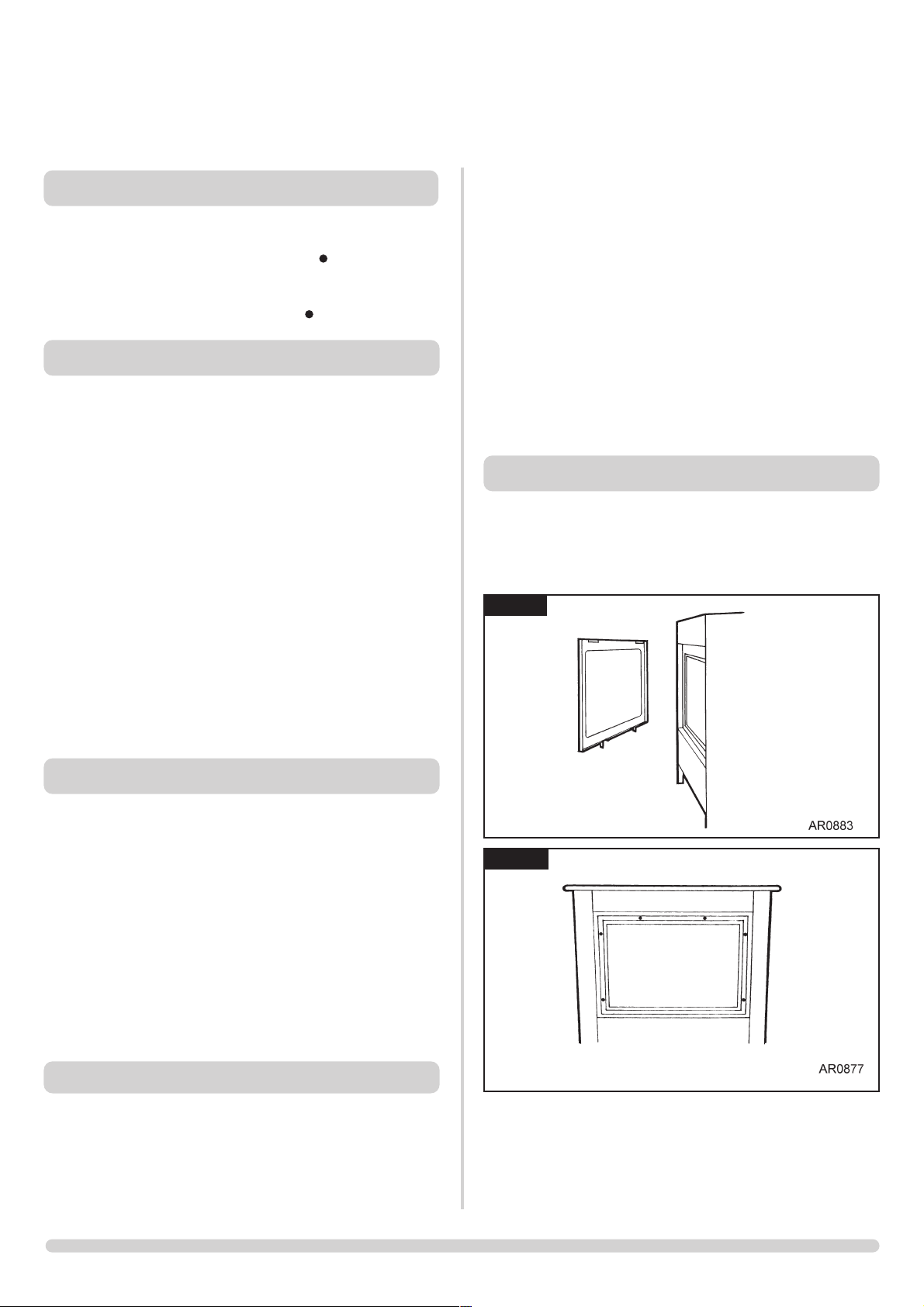
To access the ceramic fuel pieces, it will be necessary to
remove the glass door. Lift off the decorative steel trim, see
Diagram 3 and remove the 6 screws holding the glass
frame. See Diagram 4.
4. UPGRADING YOUR STOVE
5. CLEANING THE FIRE
6. FUEL BED ARRANGEMENT
USER INSTRUCTIONS
3. TURNING THE STOVE OFF
Advice on Handling and disposal of fire ceramics
3
4
Page 6
6
USER INSTRUCTIONS
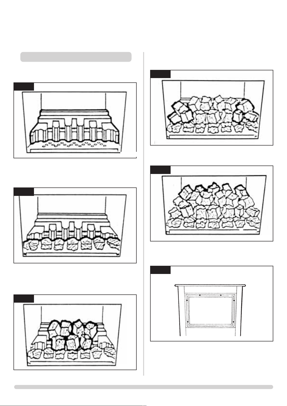
6.1 Place the flame baffle onto the shelf at the rear of the tray
and push up against the rear ledge, see diagram 5.
6.2 Locate the front coal moulding in front of the flame baffle
ensuring that the end legs sit flat against the burner skin, see
diagram 6.
6.3 Place three large coals on the front coal so that they lean
against the flame baffle, and the four large coals on the
flame baffle so that they sit on the fingers, see diagram 7.
6.4 Place two small coals at each end of the front coal so that
they lean against the flame baffle, and a further two large
coals on the flame baffle, one at each end, see diagram 8.
6.5 Place five small coals along the rear of the flame baffle,
resting against the rear ledge, see diagram 9.
6.6
Ensure that the rope seal on the back of the glass frame is
intact. Replace the glass frame ensuring that the 6 screws are
tightened evenly. DO NOT OVERTIGHTEN. see diagram 10.
NEVER OPERATE THE STOVE WHEN THE DOOR IS
REMOVED OR WHEN THE GLASS IS BROKEN.
Steel Manhattan
5
AR0365
6
AR0366
7
AR0367
8
AR0368
9
AR0369
10
AR0887
Page 7

7
7.1 The stove is fitted with the Gazco Flue Sure System, which
will act to cut off the gas supply to the burner in the event
of incorrect operation of the flue. If the system acts to cut
off the gas supply, this indicates that there is insufficient flue
pull. If this occurs a minimum of 10 minutes should be
allowed before trying to relight. Continued operation of this
safety device means there may be a serious problem with
the flue system. A qualified gas engineer should inspect this.
Do not use the stove until an engineer says it is safe to
do so.
8.1 This is a safety feature incorporated in all GAZCO fires,
which automatically switches off the gas supply if the pilot
light goes out and fails to heat the thermocouple.
9.1 The surface coating on your GAZCO stove will ‘burn off’
during the first 24 hours of operation on high, producing a
harmless and temporary odour. If the odour persists ask
your retailer for advice.
10.1 A qualified gas engineer must service the stove every 12
months. In all correspondence, always quote the appliance
type and the Serial Number found on the data badge on
the appliance.
11.1 Any purpose provided ventilation should be checked
periodically to ensure it is free from obstruction.
12.1 To assist in any future correspondence, your installer should
have completed the Appliance Commissioning Checklist in
this manual. This records the essential installation details of
this appliance. In all correspondence always quote the
Model No. and Serial No.
13.1 Parts of this appliance become hot during normal use. It is
recommended that a suitable fire guard be used for
protection of young children and the infirm. Indeed, all
parts of the appliance should be treated as a ‘working
surface’ except for the control area.
USER INSTRUCTIONS
7. GAZCO FLUE SURE SYSTEM
8. THE FLAME FAILURE DEVICE
9. 'RUNNING IN'
10. SERVICING
11. VENTILATION
12. INSTALLATION DETAILS
13. HOT SURFACES
Page 8
8
INSTALLATION INSTRUCTIONS
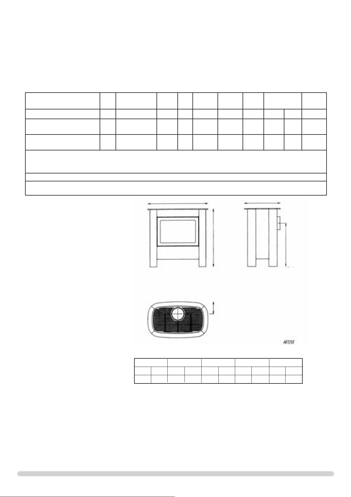
TECHNICAL SPECIFICATION
Covering Models:
MANHATTAN - 8619 - P8619
Packing Checklist
Qty Description
1 Stove
1 Flue Blanking plate
1 Flue In fill plate
1 Coal set*
1 Flame Baffle*
1 Front Coal*
1 Fixing kit containing
1 Instruction Manual
2 Wood screws
2 Rawlplugs
1 Box spanner
*Packed in appliance
Model
CAT.
Gas Gas
Type
Working
Pressure
NOX
Class
Aeration Injector Gas Rate
m3⁄h
Input kW (Gross) Country
High Low
Steel Manhattan 8619
I
2H
Naural Gas G20 20 mbar 5 ø11 mm 375 0.629
6.6
Gross
6.6
Gross
GB,IE
Steel Manhattan P8619
I
3+
LPG Propane G31
LPG Butane G30
37 mbar
29 mbar
5 ø15.5 x 2 170
0.237
0.18
6.30
Gross
3.25
Gross
GB,IE
Efficiency Class II
Flue Outlet Size 127 mm (5”) ø
Gas Inlet Connection Size 8 mm ø
Minimum flue specification T300/N2/O/D/1
Maximum flue temperature 260°C
A
AAAA
B
D
E
C
A B C D E
ins mm ins mm ins mm ins mm ins mm
27
7
/8709 27 683 163/442 177/8453 53/4145
Page 9
9
INSTALLATION INSTRUCTIONS
SITE REQUIREMENTS
1.1 The chimney or flue system must comply with the rules in
force, and must be a minimum of 127mm in diameter. (5").
1.2 The minimum height of the flue or chimney must be 3 metres
(10ft). Any horizontal flue run from the rear outlet should not
exceed 100mm from the back of the appliance.
1.3 The chimney or flue must be free from any obstruction. Any
damper plates should be removed or secured in the fully open
position and no restrictor plates should be fitted.
1.4 The chimney should be swept prior to the installation of the
appliance, but where it can be seen that the chimney is clean
and unobstructed throughout its entire length, it need not be
swept.
NOTE: If it is intended to fit the stove into an existing brickbuilt chimney without a closure plate*, a 5" (127mm) liner
must be used. Larger lined flues may work, but in some
instances could cause cold start flue problems resulting in
nuisance shutdown. Lined flues above 7" (175mm) are not
recommended.
2.1 The large stove has a rated output in excess of 7Kw and
requires a minimum of 11cm
2
permanent effective free air.
This is in addition to any window that opens, and although
it must communicate with the outside air whenver possible,
it can communicate with an adjacent room providing such
space has a similar opening to the outside. The small and
medium stoves have a rated output below 7Kw and do not
normally require any additional ventilation.
3.1 Before installation, ensure the local distribution conditions
(identification of the type of gas and pressure) and the
adjustment of the appliance are compatible.
3.2 Ensure that the gas supply is capable of delivering the
required amount of gas, and is in accordance with the rules
in force.
3.3 Soft copper tubing and soft soldered joints can be used but
must not be closer than 50mm to the base of the tray.
3.4 A means of isolating the gas supply to the appliance must
be provided, independent of any appliance control.
3.5 All supply gas pipes must be purged of any debris that may
have entered, prior to connection to the appliance.
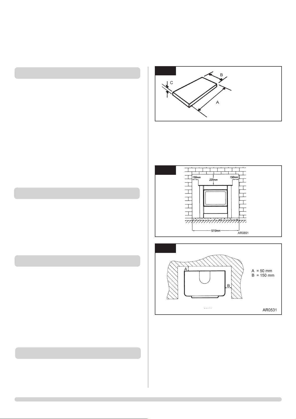
4.1 This stove must stand on a non-combustible hearth that is at
least 12mm thick and projects 50mm minimum from the
base of the stove in all directions.
4.2 Do not install in a room that contains a bath or shower.
MINIMUM CLEARANCE
4.3 The stove is not suitable for installation against a
combustible wall. All combustible materials must be
removed from behind the stove.
4.4 Ensure you comply with all minimum clearance
measurements, whether or not to combustible materials.
The above dimensions povide adequate clearance at the
side and rear of the fire so that the controls can be
reached.
2A
*
* Air-space to non-combustible
3. INSTALLATION OF THE GAS SUPPLY
2. VENTILATION
4. APPLIANCE LOCATION
2
1
1. FLUE AND CHIMNEY REQUIREMENTS
AR0604
A = 811mm
B = 527 mm
C = 12 mm
Page 10
2.7 The stove is fitted with the Gazco Flue Sure System, which
acts to cut off the gas supply to the appliance in the event
of incorrect operation of the flue. If the system acts to shut
off the gas supply, this indicates there is insufficient flue
pull. If this occurs a minimum of 10 minutes should be
allowed before trying to relight. Continued operation of this
safety device means there may be a serious problem with
the flue system and a qualified gas engineer must inspect.
DO NOT USE THE STOVE UNTIL AN ENGINEER SAYS IT
IS SAFE TO DO SO.
2.8 Do not tamper with the Flue Sure System Use only genuine
Gazco replacement parts when servicing the system - refer
to Servicing Instructions, Replacing Parts.
THE YELLOW FLAMES WILL APPEAR WHEN THE FIRE
HAS GAINED SUFFICIENT HEAT - TYPICALLY 10 TO 20
MINUTES.
3.1 Open the carton containing the engine assembly, and
carefully remove the engine. It will now be necessary to
decide upon top or rear flue exit, the stove is factory built
for rear flue exit, but it may be changed to top exit by
simply using the following method.
3.2 Remove the flue spigot from the rear of the stove and
replace with the blanking plate from the top of the stove.
Refit flue spigot to top of stove.
3.3 When installing with a top flue please note the flue pipe fits
through a hole in the top grill, the dimensions are for floor
fixing a top flue installation with clearance for side panels.
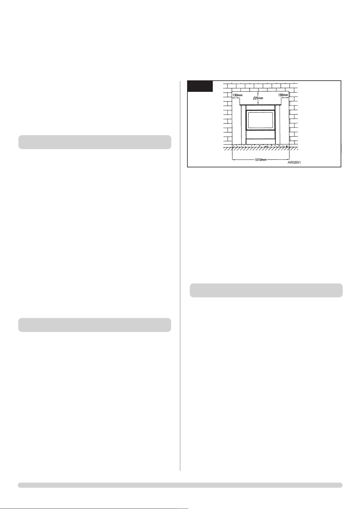
3.4 Position the engine assembly in its intended location and
mark the position of the two floor fixing holes at the base of
each side of the subframe, minimum fixing dimensions to a
rear wall are shown in diagram 2.
10
IMPORTANT: ENSURE THAT THE APPLIANCE IS
CORRECTLY ADJUSTED FOR THE GAS TYPE AND
CATEGORY APPLICABLE IN THE COUNTRY OF USE.
REFER TO DATABADGE AND TECHNICAL
SPECIFICATIONS OF THIS BOOKLET.
FOR DETAILS OF CHANGING BETWEEN GAS TYPES
REFER TO SERVICING INSTRUCTIONS, REPLACING
PARTS.
1.1 This stove is fitted with a control valve that can be easily
upgraded to battery powered remote control. There are two
versions of this control which can be obtained through your
local Gazco stockist.
1.2 This upgrade can be fitted before or after installation but if
side clearances are limited then it will be easier to upgrade
the stove before installation. Full instructions are included
with the kit.
1.3 STANDARD REMOTE CONTROL. This remote controls the
gas appliance after the pilot has been lit. It can turn the
main burner on and regulate it from low through to high
and back again. It can turn the main burner off leaving the
pilot burning GAZCO PART NUMBER 8455.
1.4 THERMOSTATIC AND TIMER REMOTE CONTROL. This
remote controls the gas appliance after the pilot has been
lit. In ‘MANUAL MODE’ it can be used to turn the main
burner on and manually regulate it from low through to
high and back again. It can also be used to turn the main
burner leaving the pilot burning. In ‘AUTO MODE’ it will
automatically regulate the room temperature to a pre-set
temperature. In ‘TIMER MODE’ it will turn the fire on and
off according to a pre-set programme and automatically
regulate the room temperature during the two ON periods.
GAZCO PART NUMBER 8456.
2.1 This appliance must be installed in accordance with the
rules in force and used only in a sufficiently ventilated
space. Place read these instructions before installation and
use of this appliance.
2.2 All the instructions must be left intact with the user.
2.3 In your own interest, and those of safety, this appliance
must be installed by a competent person in accordance
with local and national codes of practice. Failure to install
the appliance correctly could lead to prosecution.
2.4 This appliance is intended for use on a governed gas
installation and set to the required pressure.
2.5 Keep all plastic bags away from young children.
2.6 Do not place any object on or near to the stove. Allow
adequate clearance above the stove. See diagram 2,
Appliance Location..
INSTALLATION INSTRUCTIONS
INSTALLATION
1. CONTROL UPGRADE
2. SAFETY PRECAUTIONS
1
3. INSTALLATION OF THE STOVE
Page 11
11
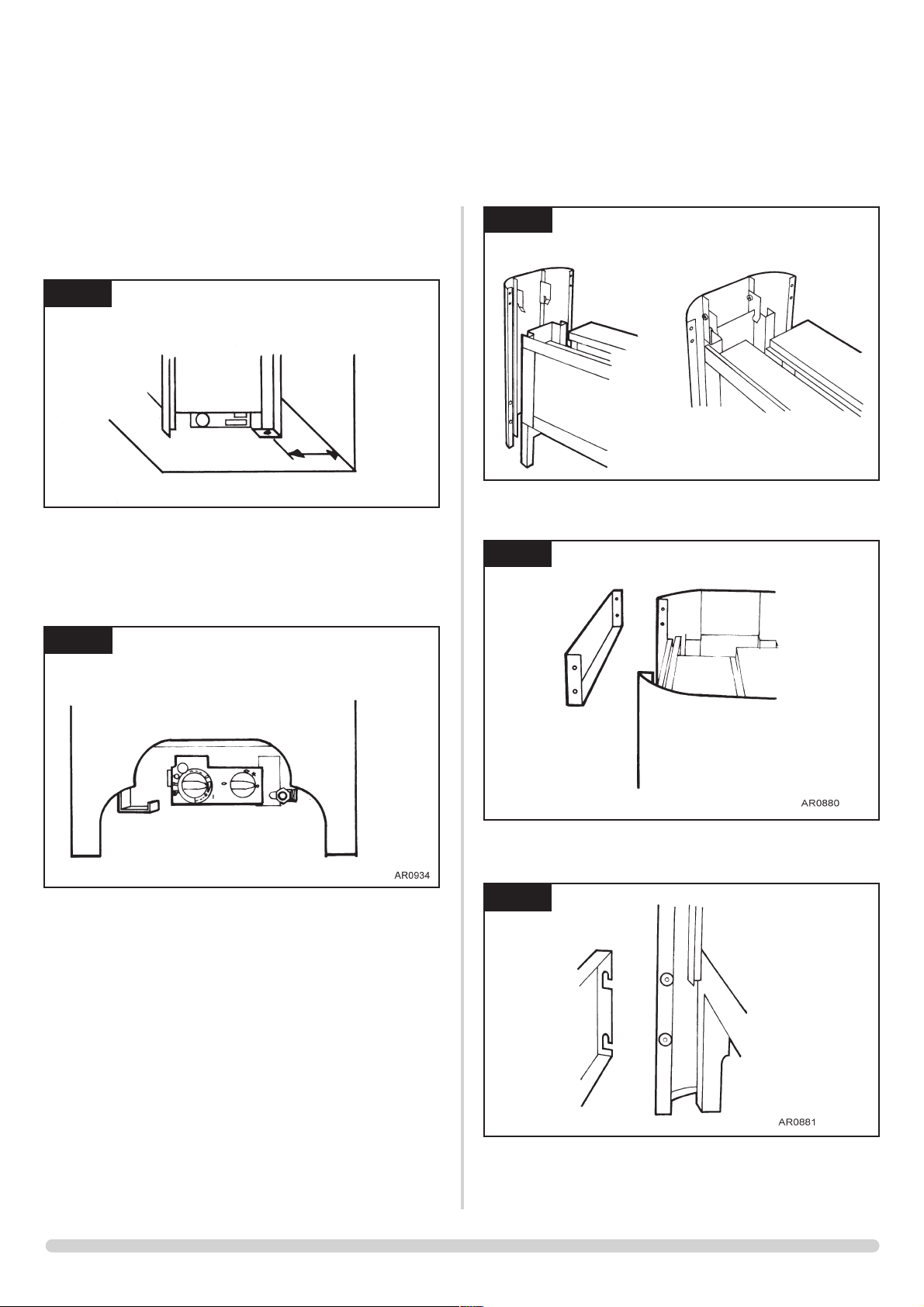
3.5 Remove the assembly and drill the two holes using a No. 12
masonry bit. Push the rawl plugs into the holes, and place
the engine assembly in position, secure to the floor using
the screws provided. See diagram 2.
3.4 Having run the gas supply to the stove, PURGE THE
SUPPLY PIPE, this is essential to expel any debris that may
block the gas controls. connect the gas supply to the 8mmcompression elbow at the RH rear corner of the stove,
ensuring that the pipe position does not interfere with the
location of the outer steel casing. See diagram 3.
3.7 Open the second carton and carefully remove the steel
outer casing components. Remove the protective plastic
coating from the two side assemblies and lower them onto
the engine assembly until the lugs locate as shown, check
that the feet are touching the hearth. See diagram 4.
3.8 Secure the upper front panel using the 4 nuts and bolts
provided. See diagram 5.
3.9 Locate the lower panels onto the lugs as shown. See
diagram 6.
INSTALLATION INSTRUCTIONS
INSTALLATION
2
AR0631
158mm
3
AR0879
AR0878
5
6
4
Page 12
1 2
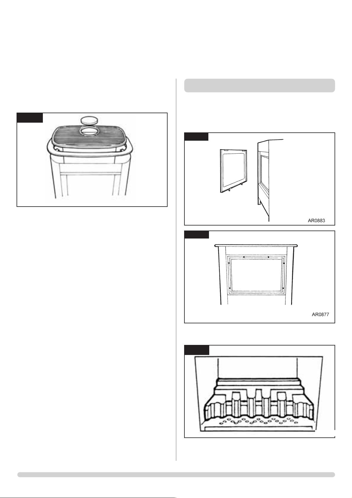
3.10 Place the steel top onto the casing so that the 2 lugs on the
underside locate the top centrally within the casing. Place
the cast iron grille into the recess in the centre of the top
panel and locate the blanking plate into the grill (if
required). See diagram 7.
3.11 Check the pull of the flue system by applying a lighted
smoke pellet to the flue system opening. If there is a
definite flow into the chimney, proceed with the
installation, if not; warm the chimney for a few minutes and
repeat the test.
IF THERE IS STILL NO DEFINITE FLOW, THE FLUE MAY
REQUIRE ATTENTION - SEEK EXPERT ADVICE.
3.12 The flue system may now be connected to the stove, ensure
that all joints are sealed with suitable fire resistant sealant. It
is also recommended that a physical retention method may
be used at the flue spigot joint, self-tapping screws being
favoured.
3.13 Connect a suitable pressure gauge to the test point located
on the inlet fitting, and turn the gas supply on. Light the
appliance and check all gas joints for possible leaks. Turn
the appliance to maximum and check that the supply
pressure is stated on the databadge. Turn the gas off and
replace the test point screw, turn the gas on and check the
test point for leaks.
To access the ceramic fuel pieces, it will be necessary to
remove the glass door. Lift off the decorative steel trim, see
Diagram 8 and remove the 6 screws holding the glass
frame. See Diagram 9.
4.1 Place the flame baffle onto the shelf at the rear of the tray
and push up against the rear ledge, see diagram 10.
INSTALLATION INSTRUCTIONS
INSTALLATION
7
AR0882
4. FUEL BED ARRANGEMENT
8
9
10
AR0365
Page 13
13
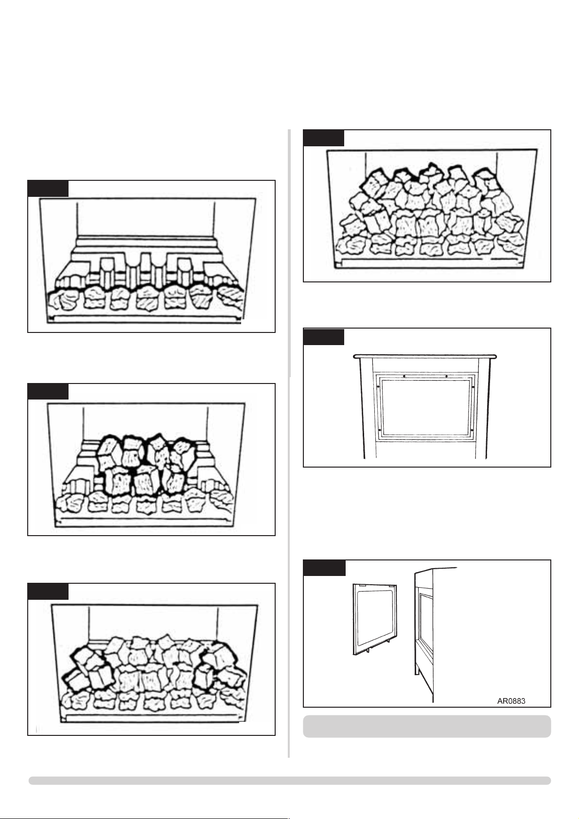
4.2 Locate the front coal moulding in front of the flame baffle
ensuring that the end legs sit flat against the burner skin, see
diagram 11.
4.3 Place three large coals on the front coal so that they lean
against the flame baffle, and the four large coals on the
flame baffle so that they sit on the fingers, see diagram 12.
4.4 Place two small coals at each end of the front coal so that
they lean against the flame baffle, and a further two large
coals on the flame baffle, one at each end, see diagram 13.
4.5 Place five small coals along the rear of the flame baffle,
resting against the rear ledge, see diagram 14.
4.6
Ensure that the rope seal on the back of the glass frame is
intact. Replace the glass frame ensuring that the 6 screws are
tightened evenly. DO NOT OVERTIGHTEN. see diagram 15.
NEVER OPERATE THE STOVE WHEN THE DOOR IS
REMOVED OR WHEN THE GLASS IS BROKEN.
4.7 Secure the glass frame assembly using the 6 screws
provided, tighten evenly and do not overtighten. See
diagram 15.
4.8 Hang the dcorative steel trim onto the glass frame as shown.
See diagram 17
5.1 Full instructions are given in Section 2.
INSTALLATION INSTRUCTIONS
INSTALLATION
11
AR0366
12
AR0367
13
AR0368
14
AR0369
15
AR0887
17
5. LIGHTING
Page 14
14
INSTALLATION INSTRUCTIONS
COMMISSIONING
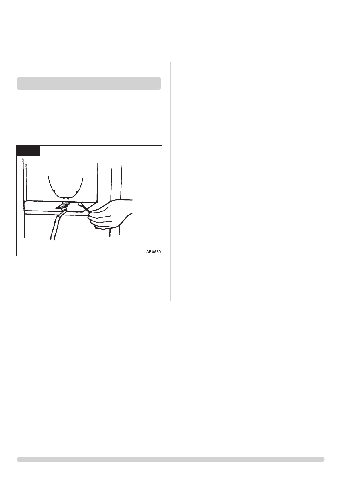
1.1 Close all openable doors and windows in the room. Ignite
the stove and operate on maximum for 10 minutes.
Position a lighted smoke match just inside the draught
diverter opening and check that all smoke is drawn into the
opening. In restricted locations a mirror can be used. See
diagram 1. If there is any doubt, run the stove for a further
10 minutes, and repeat the test.
1.2 If there are any extractor fans in adjacent rooms, the test
must be repeated with the fans running on maximum and
interconnecting doors open.
IF SPILLAGE PERSISTS, DISCONNECT THE APPLIANCE
AND SEEK EXPERT ADVICE.
For future reference record the installation details on the
Appliance Commissioning Checklist of these instructions.
1. COMMISSIONING
1
Page 15
15
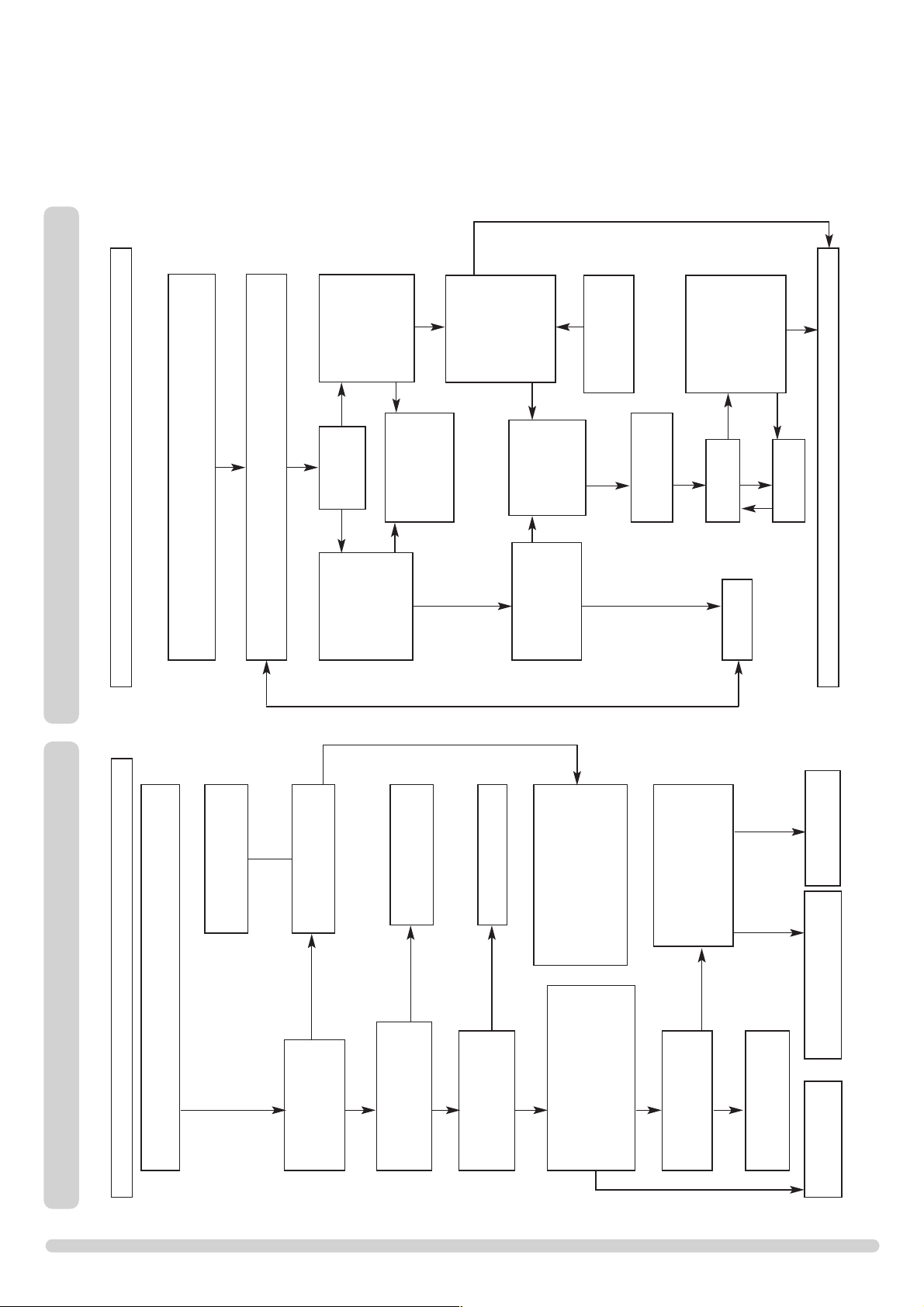
IGNITION FUNCTIONAL CHECK 1
PILOT WILL NOT LIGHT
Ensure there is no debris around the pilot assembly,
(e.g. soot, etc.) which could short the spark, clean the area.
Operate the valve.
Is there a spark?
Consult Section 2
on page 4 and retry.
Check alignment of pilot
burner head. Change the
ignition lead,
see diagram 1, Servicing
Requirements.
Check isolation tap and
gas meter, retry.
Correct and
retry.
Purge the gas pipes
and retry.
SEE 'NO SPARK'
CHART
SYSTEM OK
There is a blockage in the system, check the inlet test point,
the mag seating, valve and pilot filter.
Is the gas turned on to the
appliance?
Is the gas pressure correct?
Has the system got
any air in it?
Does the pilot light?
Is the control being
operated correctly?
Will the pilot light
with a match?
No Yes
No
Yes
No
Yes
Yes
No
No
Yes
No
No
Yes
Yes
SERVICING INSTRUCTIONS
SERVICING / FAULT FINDING CHARTS
This appliance must be serviced at least once a year by a
competent person.
All tests must be serviced by best practice as described by
the current CORGI recommendations.
Refer to ADVICE ON HANDLING AND DISPOSAL OF
FIRE CERAMICS In User Instructions section 5
1.1 Before any tests are undertaken on the appliance, conduct
a gas soundness test for the property to ensure there
are no gas leaks prior to starting work.
1.2 Before any tests are undertaken on the appliance it is also
recommended to fully check the operation of the
appliance.
1.3 Special checks
1.3.1 Clean any lint or fluff from the pilot - pay particular
attention to the aeration hole in the side of the pilot
1.3.2 Clean away any fluff or lint from under the burner
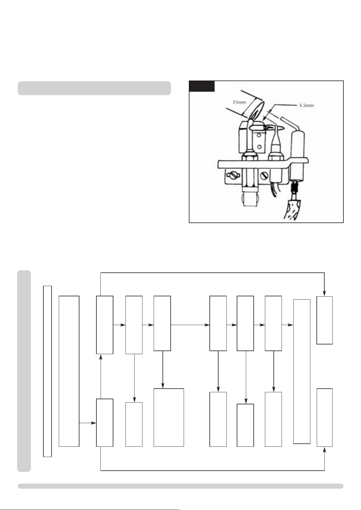
1.3.3 Check the spark gap on the pilot is correct
1.4 Correct any faults found during the initial tests and then recommission the appliance conducting the usual safety
checks.
1.5 Advise the customer of any remedial action taken.
1. SERVICING REQUIREMENTS
1
Page 16
16
SERVICING INSTRUCTIONS
FAULT FINDING CHARTS
PILOT WILL NOT STAY LIT OR FIRE GOES OUT IN USE
Ensure there is no debris around the pilot assembly,
e.g. coal, soot etc. which could short the spark, clean the area.
Problem is with the
pipework or
fittings which lead
to the fire. Correct and
retry.
Is thermocouple
connection good
in back of valve?
Replace
oxypilot.
Will pilot
stay alight?
Change mag
unit.
Is the pilot flame of the
correct length? See
diagram 1, Servicing
Requirements
Change the
pilot unit.
Will pilot
stay lit?
With the pilot
running is the gas
pressure stated on the
databadge?
With the fire running
on full is the gas at
the pressure stated
on the databadge?
Run for no more than
60 seconds
turn off, time interval
until mag unit shuts
with a click. Is this
greater than 7
seconds?
Run for a maximum of
60 seconds, turn off,
time interval until mag
unit shuts with a click.
Is this greater than 7
seconds?
Tighten the
connection and retry.
No
No
No
No
No
No
Yes
SYSTEM OK
Yes
Yes
Yes
Yes
No
Yes
Yes
No
Light the pilot and keep the control knob pushed in
at least 10 seconds before letting go.
FLAME FAILURE FUNCTIONAL CHECK
IGNITION FUNCTIONAL CHECK 2
NO SPARK
Ensure there is no debris around the pilot assembly,
(e.g. coal, soot etc.) which could short the spark, clean the area.
Consult Section 2
on page 4, retry.
Operate the valve to light
the pilot, does the valve
'click'?
Is the pIlot burner
horizontal?
See diagram 1, Servicing
Requirements
Has ignition lead
become detached or is
connection poor?
Remove the electrode lead
from electrode with insulated
pliers. Hold the tip 4mm from the
pilot pipework, is there a spark
when the valve ‘clicks’?
Is the electrode wire
detached from the piezo
in the valve?
Replace the
lead and, retry.
Correct and retry.
Check for defective or
damaged control knob spindle
or cam operation. Check for
correct location of piezo
components. Correct and retry.
Remove the electrode lead from
the piezo. Operate the valve.
Does a spark jump from the
piezo to the valve body?
Is the valve being
operated correctly?
Reset the pilot burner.
Yes
Yes
Yes
No
No
No
Yes
Yes
Yes
No
No
Replace the electrode.
Replace the electrode
lead and retry.
Replace the piezo
and gas valve and retry.
Yes
No
Page 17
17
SERVICING INSTRUCTIONS
REPLACING PARTS
1.1 All principal components can be replaced without removing
the stove from its installation, although it will be necessary
to remove the door and steel outer casing in order to access
most components. In order to remove the casing, using the
following procedure:
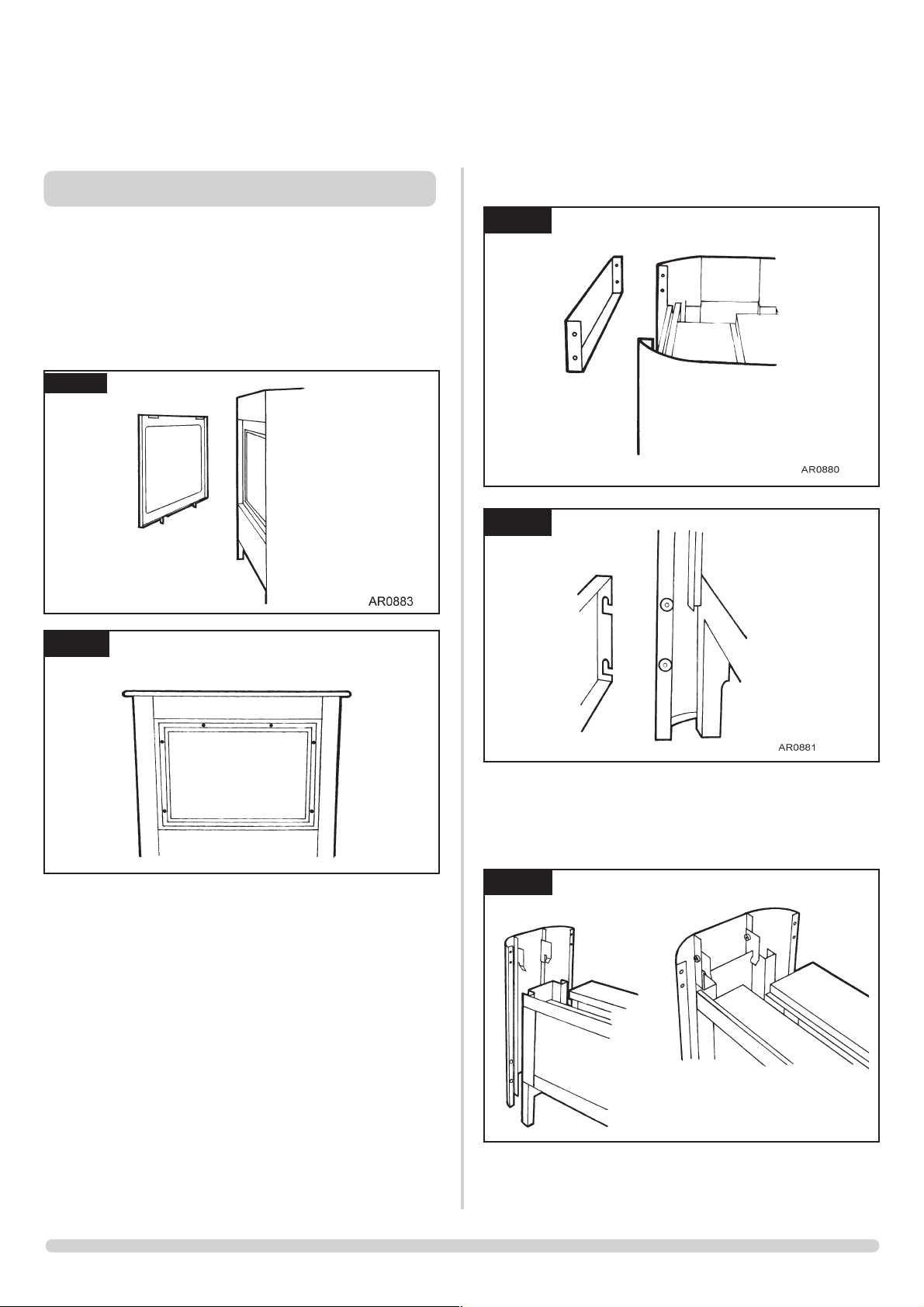
1.2 Lift off the decorative steel trim see diagram 1 and remove
the 6 screws holding the glass frame. See diagram 2.
1.3 Carefully remove the top blanking plate and cast iron grille
and place to one side, remove the steel top, see diagram
16. If the unit has been connected to the top exit flue, it
will be necessary to lift the support the grille and steep top
whilst removing the outer steel casing.
1.4 Remove the two front panels as shown. See diagrams 3 and
4.
1.5 Lift the RH decorative panel to disengage from its locating
brackets and remove from the stove, see diagram 4. It may
not be necessary to remove the LH side.
1.6 This should allow full access to all major components.
1
2
AR0887
3
1. GENERAL
4
AR0879
AR0878
5
Page 18
18
2.4 Remove the 2 screws attaching burner to back of unit, see
diagrams 4. Carefully withdraw burner unit upwards and tilt
to remove the burner through door opening. Remove the 2
screws holding the heat shield in place.
Replace in reverse order checking all joints for leaks.
3.1 Remove the burner module as described in Servicing
Section 2 above. Carefully cut the cable ties holding the
thermocouple to the pilot pipe. Remove the HT lead from
the electrode, undo the two retaining screws and remove
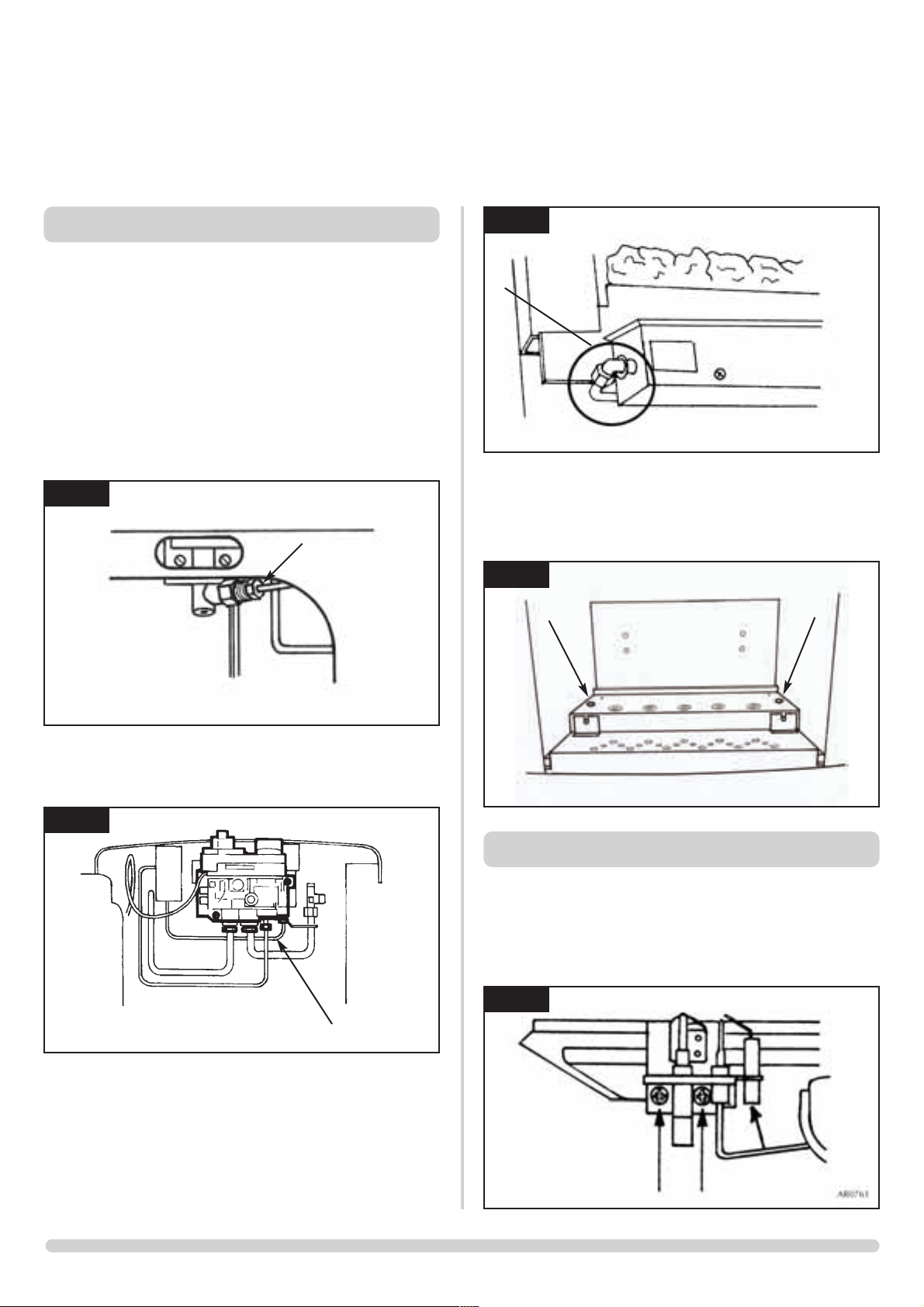
the pilot. See diagram 5.
2.1 Turn the gas supply off at the isolation device. Ensure the
unit is cool.
Use cover material to front of appliance to protect
paintwork etc.
Remove the door and place to one side. (4 nuts).
Carefully remove the ceramic fuel components to a safe
place.
Remove front cover-plate (2 screws).
Remove cover plate fixing bracket (2 wing nuts).
(Small Stoves only)
Unscrew pilot union nut on gas valve. See diagram 1.
2.2 Disconnect thermocouple from gas valve. See diagram 2.
Remove ignition lead from electrode. (Cut cable tie to
ignition lead if required).
2.3 Loosen main injector nut on airbox and disconnect from
injector, see diagram 3, A.
SERVICING INSTRUCTIONS
REPLACING PARTS
2. BURNER UNIT REMOVAL
1
2
3
4
A
AR0391
AR0943
AR0498
AR0385
Viewing slot on Marlborough only
A
3. PILOT UNIT
5
Page 19
19
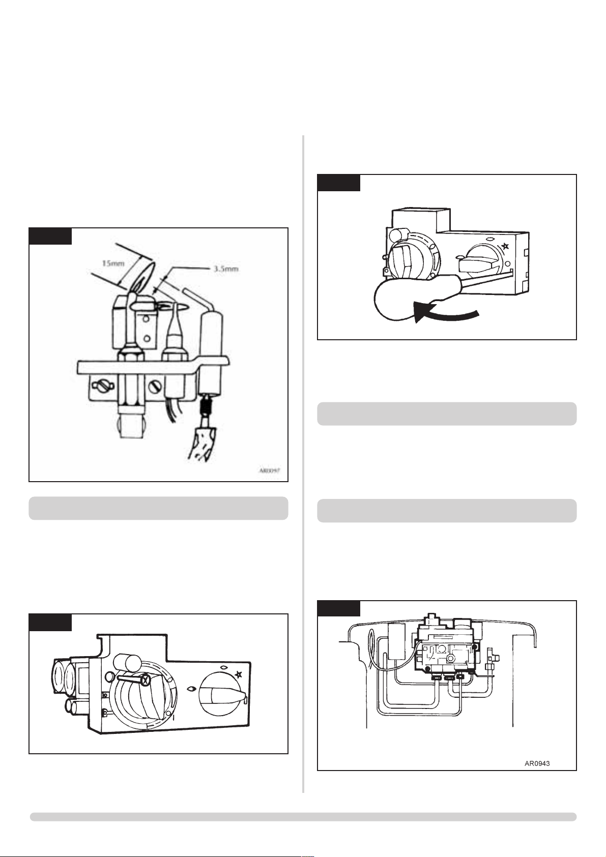
3.2 When replacing the pilot ensure the thermocouple follows
its original route, i.e. along the pilot pipe. Attach the
thermocouple to the pipe with new cable ties.
3.3 Set the spark gap. See diagram 6.
4.1 Gain access to the back of the pilot assembly, (see section
2) and disconnect the ignition lead from the electrode.
4.2 Remove the front cover from the control valve, (see
diagrams 7 and 8). Disconnect the other end of the ignition
lead from the valve body. Note the existing route of the
ignition lead.
4.3 Replace with a new ignition lead following the same route
as the old one. Replace the valve cover and the pilot
assembly.
4.4 Check operation of the new ignition lead.
5.1 The piezo assembly used on this appliance is not
serviceable and is unlikely to fail.
5.2 If a new piezo is required it will be necessary to change the
gas valve. Refer to Section 6.
6.1 Turn the gas supply off at the isolation device.
6.2 Disconnect the 2x8mm and 1x4mm gas pipe fittings at the
back of the gas valve and also disconnect the
thermocouple, see diagram 9.
SERVICING INSTRUCTIONS
REPLACING PARTS
4. IGNITION LEAD AND PIEZO
5. PIEZO
6
7
8
AR0915
AR0916
6. GAS VALVE
9
Page 20
20
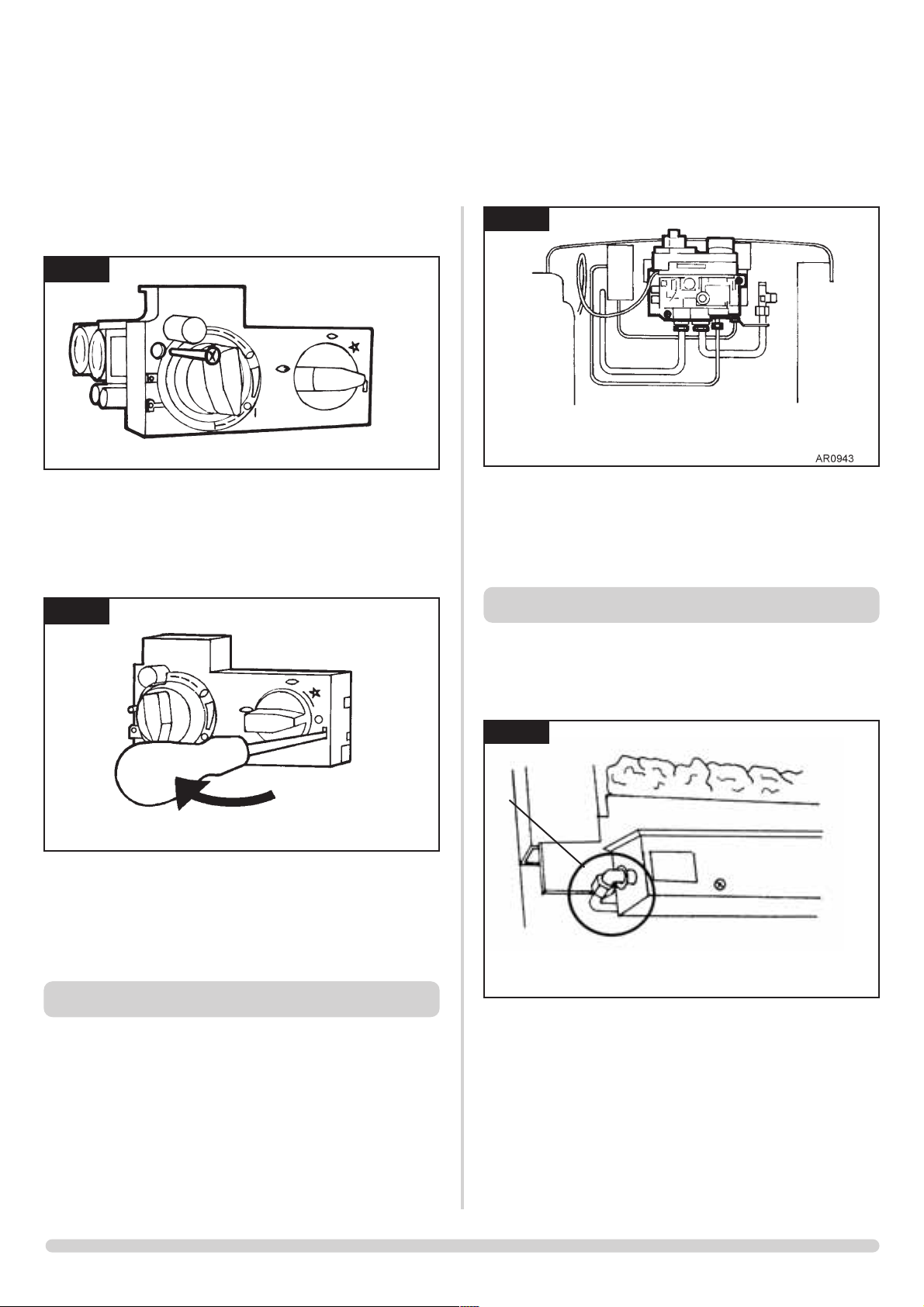
6.3 Undo the single screw that secures the left-hand side of the
control cover, see diagram 10.
6.4 To release the right-hand side of the control cover, insert
the narrow blade screwdriver into the slot shown in diagram
11. Lever it gently and pull from the right-hand side at the
same time. The cover will now come off. There is a small
cylindrical metal spacer inside the cover. This must be kept
and replaced on the fixing screw during re-assembly.
6.5 Disconnect the ignition lead from the gas valve.
6.6 Undo the two bolts securing the gas valve to the appliance
and remove the valve.
6.7 Replace in reverse order.
6.8 Check all joints for gas leaks. Check operation of the
thermocouple and ignition lead.
7.1 Turn the gas supply off at the isolation device. Undo the
thermocouple connection from the back of the gas valve.
Pull the sensor leads clear and remove the interrupter
block.
7.2 Undo the magnetic valve-retaining nut from the back of the
control valve. Gently tap out the magnetic valve and replace
with a new unit. Replace the retaining nut and tighten. See
diagram 12.
7.3 Reassemble the interrupter block and leads. Secure the
thermocouple connection in the rear of the gas control. (Do
not overtighten). Turn the gas supply on and check the
entire pipework and valve joints for any leaks.
8.1 Turn the gas supply off at the isolation device. Locate the
main injector on the LH side of the airbox, undo the
compression nut and pull the pipe clear of the injector
body, see diagram 13,A.
8.2 Rotate the injector until it is fully removed, and install the
correct replacement injector. Reassemble and turn the gas
supply on, check for leaks.
.
SERVICING INSTRUCTIONS
REPLACING PARTS
7. MAGNETIC SAFETY VALVE
10
11
AR0915
AR0916
12
8. MAIN INJECTOR
13
A
AR0498
Page 21
21
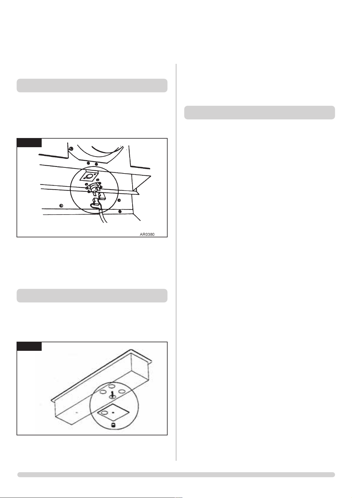
If the stove has been installed in a restrictive location, it
may be necessary to remove the stove from its location.
9.1 Locate the sensor in the draught diverter opening, and
gently pull the two wires off the terminals. Undo the two
taptite screws and remove the sensor and the two plastic
spacers. See diagram 14.
9.2 Refit a new sensor ensuring the spacers are located between
the sensor and the bracket. Replace the two leads.
9.3 If it has been necessary to remove the stove, ensure that all
disturbed gas joints are checked for gas soundness when
reinstalled, and repeat the flue clearance test as detailed in
the Commissioning Section.
10.1 Turn the gas supply off at the isolation device.
10.2 Locate the aeration plate on the underside of the airbox
and remove the Nyloc nut, see diagram 15.
10.3 Remove the plate and replace with the correct size, ensure
that the hole(s) in the plate align correctly with the holes in
the underside of the airbox and replace the Nyloc nut.
11.1 In order to change between gas types, it will be necessary
to change the following items.
• Pilot Unit
• Control Valve
• Main Injector
• Aeration Plate (if required)
• Databadge
The relevant parts can be ordered as a conventional kit
from Gazco. Always quote the appliance type and serial
number when ordering spare parts.
** NOTE: THE CONTROL VALVE IS FACTORY PRESET
FOR CORRECT GAS TYPE AND MODEL. A NEW UNIT
WILL NEED TO BE ORDERED WHEN CHANGING
BETWEEN GAS TYPES.
SERVICING INSTRUCTIONS
REPLACING PARTS
14
15
9. GAZCO FLUE SURE SYSTEM
10. PRIMARY AERATION PLATE
11. CHANGING BETWEEN GAS TYPES
AR0381
Page 22
22
SERVICING INSTRUCTIONS
REPLACING PARTS
12. CONTROL UPGRADE
See Installation, section 1.
* Set for Appliance
13. SHORT SPARES LIST
Components
Steel Manhattan
NG LPG
Pilot Unit
P10036 P10037
Injector
IN0045 IN0006
Aeration Plate
ME1071 ME0834
Gas Valve
GC0088K*
Flue Sensor
EL0001
Sensor Lead x 2
EL0064
Inerrupter
GC0026
Mag Unit
GC0092
Ignition Lead
GC0090
Rear Panel
-
Flame Baffle
CE0120
Front Coal
CE0124
Coal Set
CE0136
Burner Skin
CE0116
Upgrade Kit Std
8455
Upgrade Kit Std Thermostatic
8456
Page 23

23
SERVICE RECORDS
1ST SERVICE
Date of Service:...........................................................................
Next Service Due:.......................................................................
Signed:........................................................................................
Dealer's Stamp/CORGI Registration Number
3RD SERVICE
Date of Service:...........................................................................
Next ServiceDue:........................................................................
Signed:........................................................................................
Dealer's Stamp/CORGI Registration Number
5TH SERVICE
Date of Service:...........................................................................
Next Service Due:.......................................................................
Signed:........................................................................................
Dealer's Stamp/CORGI Registration Number
7TH SERVICE
Date of Service:...........................................................................
Next Service Due:.......................................................................
Signed:........................................................................................
Dealer's Stamp/CORGI Registration Number
9TH SERVICE
Date of Service:...........................................................................
Next Due:...................................................................................
Signed:........................................................................................
Dealer's Stamp/CORGI Registration Number
2ND SERVICE
Date of Service:...........................................................................
Next Service Due:.......................................................................
Signed:........................................................................................
Dealer's Stamp/CORGI Registration Number
4TH SERVICE
Date of Service:...........................................................................
Next Service Due:.......................................................................
Signed:........................................................................................
Dealer's Stamp/CORGI Registration Number
6TH SERVICE
Date ofService:............................................................................
Next Service Due:.......................................................................
Signed:........................................................................................
Dealer's Stamp/CORGI Registration Number
8TH SERVICE
Date of Service:...........................................................................
Next Due:...................................................................................
Signed:........................................................................................
Dealer's Stamp/CORGI Registration Number
10TH SERVICE
Date of Service:...........................................................................
Next Service Due:.......................................................................
Signed:........................................................................................
Dealer's Stamp/CORGI Registration Number
Page 24

24
Page 25

25
Page 26

Gazco Limited, Osprey Road, Sowton Industrial Estate, Exeter, Devon, England EX2 7JG
Tel: (01392) 261999 Fax: (01392) 444148 E-mail: [email protected]
A member of the Stovax Group
 Loading...