


Operator’s Manual
GAS/OIL
RATIO
50:1
Water Pump
SS14CW
SN
Check for parts online at www.stormsurgepumps.com or call 800-345-6007 M-F 8-5
Product Number:
20198
P/N: 22541
ECN: 10829
REV 1: 05/01/15
© 2015 Ardisam, Inc.
All Rights Reserved

Operator’s Manual
SS14CW Water Pump
INTRODUCTION
Congratulations on your investment in quality. Thank you for purchasing a water pump from Storm Surge™. We have worked to
ensure that your pump meets the highest standards for usability and durability. With proper care, your pump will provide many
years of service.
Please read this entire manual before installation and use. Storm Surge™ reserves the right to change, alter or improve the
product and this document at any time without prior notice.
CONTENTS
Introduction ................................................................................................................................................................................................................................... 2
Pump Specications .................................................................................................................................................................................................................... 3
Warnings and Safety Precautions ....................................................................................................................................................................................... 4-7
Component Identication .........................................................................................................................................................................................................8
Installation ...................................................................................................................................................................................................................................... 9
Pump Placement ........................................................................................................................................................................................................................10
Operation ............................................................................................................................................................................................................................... 11-12
Maintenance and Storage ................................................................................................................................................................................................ 13-15
Troubleshooting and Repair ............................................................................................................................................................................................15-17
Parts Breakdown .................................................................................................................................................................................................................. 18-21
Warranty ........................................................................................................................................................................................................................................22
Maintenance Schedule .............................................................................................................................................................................................................23
Federal Emission Control Warranty Statement ......................................................................................................................................................... 24-25
Federal Emission Information
Viper® warrants to the retail purchaser, that this small, oroad engine was designed, built and equipped to conform at
the time of initial sale to all applicable regulations of the U.S.
Environmental Protection Agency (EPA) and those of the State
of California (CARB).
Record the model number and serial number in the space
provided for easy reference (For serial number location SEE
FIGURE 1). Warranty is valid only if the completed registration
is received by Storm Surge™ within 30 days of purchase.
You can register your warranty online by visiting www.
stormsurgepumps.com. If you do not have a computer, call
our customer service department at (800) 345-6007 Monday
through Friday from 8 a.m. to 5 p.m. CST.
FIGURE 1
SERIAL NUMBER
DECAL
OWNERSHIP RECORDS
Owner’s Name:
Owner’s Address:
City: State/Province: Zip Code/Postal Code:
Model Number: Serial Number:
Date of Purchase:
Notes:
This manual may contain information for several models. Read and keep this manual for future reference. This manual contains important
information on SAFETY, ASSEMBLY, OPERATION, AND MAINTENANCE. The owner must be certain that all the product information is included with
the unit. This information includes the MANUAL, the REPLACEMENT PARTS and the WARRANTIES. This information must be included to make sure
state laws and other laws are followed. This manual should remain with the product even if it is resold.
2
Check for parts online at www.stormsurgepumps.com or call 800-345-6007 M-F 8-5

0 500 1,000
Discharge Capacity (gal/hr)
Total Lift/Head (ft)
1,500 2,000
15
30
45
60
75
90
SS14CW
PERFORMANCE DATA
PUMP SPECIFICATIONS
SPECIFICATIONS
Engine Viper® 40cc 4-cycle
Ignition Type Electronic Ignition
Cooling System Forced Air Cooling
Spark Plug Type / Gap (mm) NGK CMR6A / 0.6
Recommended Fuel Type Minimum 87 octane with NO ethanol content
Operator’s Manual
SS14CW Water Pump
NOTE: If using an ethanol blended fuel, a fuel stabilizer, mixed
to manufacturer specications, is recommended
Oil Type Viper® 10W-30 4-cycle oil (P/N 13235)
Fuel Capacity (gal) 0.21
Oil Capacity (-oz) 3.72
Inlet/Outlet 1” NPSH
Run Time (hrs) 1.2
Suction Lift (ft) 16
Total Head (ft) 65
Flow Rate (gpm/gph) 26.4/1585
Max Solid Size (in) 0.5
Overall Dimensions (in) 12 x 11 x 13.5
Weight (lb) 17.5
All weights, specications and features are approximate and are subject to change without notice.
Check for parts online at www.stormsurgepumps.com or call 800-345-6007 M-F 8-5 3

WARNINGS AND SAFETY PRECAUTIONS
Operator’s Responsibility
Accurate assembly and safe and eective use of the machine is
the operator’s responsibility.
• Read and follow all safety instructions.
• Carefully follow all assembly instructions.
• Maintain the machine according to directions and
schedule included in this Storm Surge™ operator’s
manual1.
• Ensure that anyone who uses the machine is familiar
with all controls and safety precautions.
Operator’s Manual
SS14CW Water Pump
WARNING
WARNING INDICATES A HAZARD WHICH, IF NOT
AVOIDED, COULD RESULT IN DEATH OR SERIOUS
INJURY AND/OR PROPERTY DAMAGE.
CAUTION
CAUTION INDICATES YOU CAN BE HURT OR
YOUR EQUIPMENT DAMAGED IF THE SAFETY
INSTRUCTIONS THAT FOLLOW THIS SIGNAL
WORD ARE NOT OBEYED.
Special Messages
Your manual contains special messages to bring attention to
potential safety concerns, machine damage as well as helpful
operating and servicing information. Please read all the
information carefully to avoid injury and machine damage.
NOTE: General information is given throughout the
manual that may help the operator in the
operation or service of the machine.
This symbol points out important safety
instructions which if not followed could
endanger your personal safety.
Before Operating Engine:
NOTE: Please read this section carefully: Read entire
operating and maintenance instructions for this
product and the engine which accompanies it.
Failure to follow instructions could result in serious
injury or death. Operate the machine according
to the safety instructions outlined here and
inserted throughout the text. Anyone who uses this
machine must read the instructions and be familiar
with the controls.
IMPORTANT
IMPORTANT INDICATES HELPFUL INFORMATION
FOR PROPER ASSEMBLY, OPERATION, OR
MAINTENANCE OF YOUR EQUIPMENT.
WARNING
CALIFORNIA PROPOSITION 65 WARNING
ENGINE EXHAUST FROM THIS PRODUCT
CONTAINS CHEMICALS KNOWN TO THE STATE OF
CALIFORNIA TO CAUSE CANCER, BIRTH DEFECTS,
OR OTHER REPRODUCTIVE HARM.
WARNING
YOU MUST READ, UNDERSTAND AND COMPLY
WITH ALL SAFETY AND OPERATING INSTRUCTIONS
IN THIS MANUAL BEFORE ATTEMPTING TO SETUP
AND OPERATE YOUR MACHINE.
FAILURE TO COMPLY WITH ALL SAFETY AND
OPERATING INSTRUCTIONS CAN RESULT IN LOSS
OF MACHINE CONTROL, SERIOUS PERSONAL
INJURY TO YOU AND/OR BYSTANDERS, AND RISK
OF EQUIPMENT AND PROPERTY DAMAGE. THE
TRIANGLE IN THE TEXT SIGNIFIES IMPORTANT
CAUTIONS OR WARNINGS WHICH MUST BE
FOLLOWED.
WARNING
DO NOT USE TO PUMP FLAMMABLE OR EXPLOSIVE
FLUIDS SUCH AS GASOLINE, FUEL OIL, KEROSENE,
ETC. DO NOT USE IN FLAMMABLE AND/OR
EXPLOSIVE ATMOSPHERES. PUMP SHOULD ONLY
BE USED TO PUMP WATER. FAILURE TO FOLLOW
THIS WARNING CAN RESULT IN PERSONAL INJURY
AND/OR PROPERTY DAMAGE.
4
1
If the maintenance schedule and specications contained in this
document do not match the Federal Emission Control Warranty
Statement, the Federal Emission Control Warranty Statement
supersedes the information in this document.
Check for parts online at www.stormsurgepumps.com or call 800-345-6007 M-F 8-5

Operator’s Manual
SS14CW Water Pump
GENERAL SAFETY RULES
Read, understand, and follow all instructions on the machine
and in the manual(s). Be thoroughly familiar with the controls
and the proper use of the machine before starting.
Use this equipment for its intended purpose only.
Familiarize yourself with all of the safety and operating
decals on this equipment and on any of its attachments or
accessories.
Only allow responsible individuals who are familiar with the
instructions to operate the machine. Do not allow children
to operate this machine. Do not allow adults to operate the
machine without proper instruction.
Wear appropriate clothing such as a long-sleeved shirt or
jacket. Also wear long trousers or slacks. Do not wear shorts.
Never wear sandals, sneakers, or open shoes, and never
operate the machine with bare feet.
Do not wear loose clothing or jewelry. They can get caught in
moving parts. Always keep hands, feet, hair and loose clothing
away from any moving parts on engine and machine.
Always wear safety goggles or safety glasses with side shields
when operating the machine to protect your eyes from foreign
objects which can be thrown from the unit. Always wear a
protective hearing device.
Always wear work gloves and sturdy footwear. Wear footwear
that will improve footing on slippery surfaces. Leather work
shoes or short boots work well for most people.
Use the correct personal protection at all times. Do not
operate the machine without proper guards or other safety
protective devices in place.
See manufacturer’s instructions for proper operation and
installation of accessories. Only use accessories approved by
the manufacturer.
Operate only in daylight or good articial light.
Do not operate product when fatigued or under the inuence
of alcohol, drugs or other medication which can cause
drowsiness or aect your ability to operate this machine safely.
Watch for trac whenever you are operating near, or when
crossing roads.
If the equipment should start to vibrate abnormally, stop the
engine (motor), disconnect the spark plug wire and prevent
it from touching the spark plug. Check immediately for cause.
Vibration is generally a warning of trouble. If the noise or
vibrations of the machine increase, stop immediately and
perform an inspection.
Regularly inspect the machine. Make sure parts are not bent,
damaged or loose. Keep all screws, nuts and bolts tight.
Temperature of muer and nearby areas may exceed 150°
F (65° C). Allow muer and engine areas to cool before
touching.
Prolonged exposure to noise and vibration from gasoline
engine-powered equipment should be avoided. Take
intermittent breaks and/or wear ear protection from engine
noise as well as heavy work gloves to reduce vibration in the
hands.
Do not pick up, carry, or transport the machine from one place
to another with the engine running.
Check local regulations for age restrictions on use of this
machine.
Product-Specic Safety Rules
Never attempt to operate the pump without priming the
housing.
If an object becomes lodged in the pump, turn engine o.
Allow to cool before attempting to remove the foreign object.
Do not use torches or apply excessive heat, re or ames to
this pump as an explosion can result.
Complete pump and piping system MUST be protected
against freezing temperatures. Failure to do so could cause
serious damage and voids the warranty.
Do not run pump dry. Water is required to lubricate the shaft
seal.
Pumping chemicals or corrosive liquids with this pump is NOT
ALLOWED and can be hazardous to the operator. This pump is
intended for water only.
Always use a intake strainer with this pump to lter large
material.
Pump should be located and should rest on solid foundation.
Do not suspend the pump by means of the discharge pipe.
Check for parts online at www.stormsurgepumps.com or call 800-345-6007 M-F 8-5 5

Operator’s Manual
SS14CW Water Pump
WARNING
ENGINES GIVE OFF CARBON MONOXIDE, AN
ODORLESS, COLORLESS, POISONOUS GAS.
CARBON MONOXIDE MAY BE PRESENT EVEN IF
YOU DO NOT SMELL OR SEE ANY ENGINE EXHAUST.
BREATHING CARBON MONOXIDE CAN CAUSE
NAUSEA, FAINTING OR DEATH, IN ADDITION TO
DROWSINESS, DIZZINESS AND CONFUSION.
IF YOU EXPERIENCE ANY OF THESE SYMPTOMS,
SEEK FRESH AIR AND MEDICAL ATTENTION
IMMEDIATELY.
ENGINE SAFETY PRECAUTIONS
If your product comes with a separate engine manual, be
sure to read and follow all safety and warning precautions
outlined there, in addition to any in this manual.
Preventing Carbon Monoxide Poisoning:
• Always start and run engine outdoors. Do not start
or run engine in an enclosed area, even if doors or
windows are open.
• Never try to ventilate engine exhaust indoors. Carbon
monoxide can reach dangerous levels very quickly.
• Never run engine outdoors where exhaust fumes may
be pulled into a building.
• Never run engine outdoors in a poorly ventilated area
where the exhaust fumes may be trapped and not
easily taken away. (Examples include: in a large hole
or areas where hills surround your working area.)
• Never run engine in an enclosed or partially enclosed
area. (Examples include: buildings that are enclosed
on one or more sides, under tents, car ports or
basements.)
• Always run the engine with the exhaust and muer
pointed in the direction away from the operator.
• Always keep the throttle in the “slow” position when not
in use.
• Never point the exhaust muer towards anyone.
People should always be many feet away from the
operation of the engine and its attachments.
• Do not change the engine governor settings or overspeed the engine.
CAUTION
HOT GASES ARE A NORMAL BYPRODUCT OF A
FUNCTIONING INTERNAL COMBUSTION ENGINE.
FOLLOW ALL SAFETY INSTRUCTIONS TO PREVENT
BURNS AND FIRES.
DO NOT ALTER OR MODIFY ENGINE:
NEVER ALTER OR MODIFY THE ENGINE FROM
THE FACTORY. SERIOUS INJURY OR DEATH MAY
OCCUR IF ENGINE IS MODIFIED OR ALTERED.
WHEN WORKING ON OR REPLACING PARTS FOR
THE ENGINE OR PRODUCT, YOU MUST ALWAYS
DISCONNECT SPARK PLUG WIRE FROM THE SPARK
PLUG AND KEEP IT AWAY FROM THE SPARK PLUG.
USE EXTRA CARE IN HANDLING GASOLINE AND
OTHER FUELS. THEY ARE FLAMMABLE AND
VAPORS ARE EXPLOSIVE.
Gasoline Fires and Handling Fuel Safely
• When storing extra fuel be sure that it is in an
appropriate container and away from any re hazards.
• Prevent re and explosion caused by static electric
discharge. Use only nonmetal, portable fuel
containers approved by the Underwriter’s Laboratory
(U.L.) or the American Society for Testing & Materials
(ASTM).
• Always ll fuel tank outside in a well ventilated area.
Never ll your fuel tank with fuel indoors. (Examples
include: basement, garage, barn, shed, house, porch,
etc.) Never ll tank near appliances with pilot lights,
heaters, or other ignition sources. If the fuel has to be
drained, this should be done outdoors. The drained
fuel should be stored in a container specically
designed for fuel storage or it should be disposed of
carefully.
• Never remove the fuel cap or add fuel with the engine
running. Stop engine and allow to cool before lling.
• Do not smoke while handling fuel or operating pump.
• Never drain fuel from engine in an enclosed area.
• Always wipe up excess (spilled) fuel from engine
before starting. Clean up spilled fuel immediately.
If fuel is spilled, do not start the engine but move
product and fuel container from area. Clean up spilled
fuel and allow to evaporate and dry after wiping and
before starting.
• Allow fuel fumes/vapors to escape from the area
before starting engine.
6
Check for parts online at www.stormsurgepumps.com or call 800-345-6007 M-F 8-5

Operator’s Manual
SS14CW Water Pump
• Test the fuel cap for proper installation before starting
and using engine.
• Always run the engine with fuel cap properly installed
on the engine.
• Never siphon fuel by mouth to drain fuel tank.
• Always have an adult ll the fuel tank and never allow
children to fuel the engine.
• Never allow an adult or anyone under the inuence of
drugs or alcohol to fuel engine.
• When storing gasoline or equipment with fuel in the
tank, store away from furnaces, stoves, water heaters
or other appliances that have a pilot light or other
ignition source because they can ignite gasoline
vapors.
Burns and Fires
• The muer, muer guard, and other parts of the
engine become extremely hot during the operation
of the engine. These parts remain extremely hot after
the engine has stopped.
Prevention of Burns and Fires
• Never remove the muer guard from the engine.
• Never touch the muer guard because it is extremely
hot and will cause severe burns.
• Never touch parts of the engine that become hot after
operation.
• Always keep materials and debris away from muer
guard and other hot parts of the engine to avoid res.
Children and bystanders
Tragic accidents can occur if the operator is not alert to the
presence of children and/or bystanders. Never assume that
others will remain where you last saw them.
• Keep the area of operation clean of all persons,
especially small children and pets. Keep children
under the watchful care of a responsible adult.
• Be alert and if necessary, turn machine o if children
enter the area.
• Never allow children to operate the machine.
Service
• Always stop the engine whenever you leave the
equipment, before cleaning, repairing or inspecting
the unit. Engine should be turned o and cool, spark
plug wire must be removed from spark plug before
any repairs or adjustments are attempted. Never
make adjustments or repairs with the engine (motor)
running. Disconnect the spark plug wire and keep
the wire away from the plug to prevent accidental
starting.
• Use the correct personal protection when you make
adjustments or repairs.
• Keep all nuts and bolts tight and keep equipment in
good condition.
• Never tamper with safety devices. Check their proper
operation regularly.
• When servicing or repairing the machine, do not tip the
machine over or up unless specically instructed to do
so in this manual. Service and repair procedures can be
done with the machine in an upright position. Some
procedures will be easier if the machine is lifted on a
raised platform or working surface.
• To reduce re hazard, keep engine free of grass,
leaves, or other debris build-up. Clean up oil or fuel
spillage. Allow machine to cool before storing.
• Clean and replace safety and instruction decals as
necessary.
• To guard against engine over-heating, always have
engine debris lter mounted and clean.
• Inspect machine before storage. When not in use
store indoors in a dry place locked or otherwise
inaccessible to children.
• Use only original equipment parts from Storm
Surge™, including all nuts and bolts.
Check for parts online at www.stormsurgepumps.com or call 800-345-6007 M-F 8-5 7

COMPONENT IDENTIFICATION
THROTTLE
LOCATION
Clear Water Pump (SEE FIGURE 2.)
MUFFLER
OIL FILL
PORT
LOCATION
FRAME
Operator’s Manual
SS14CW Water Pump
LEVER
WATER
PRIMING
FILLER
CAP
INTAKE
(SUCTION)
PORT
ON/OFF
SWITCH
OUTLET
(DISCHARGE)
PORT
AIR
FILTER
PRIMER BULB
PUMP
DRAIN
PLUG
SPARK PLUG
ACCESS PANEL
FUEL TANK
CAP
RECOIL
STARTER
GRIP
CHOKE
LEVER
FIGURE 2
8
Check for parts online at www.stormsurgepumps.com or call 800-345-6007 M-F 8-5

Operator’s Manual
1
SS14CW Water Pump
CAUTION
DO NOT USE A COLLAPSIBLE INTAKE SUCTION
HOSE. USE ONLY NONCOLLAPSIBLE BRAIDED
REINFORCED INTAKE HOSE. HOSE CAN COLLAPSE
UNDER SUCTION FORCE.
DO NOT USE AN INTAKE HOSE WITH A DIAMETER
SMALLER THAN THE PUMP INTAKE PORT.
DO NOT OVER TIGHTEN HOSE CLAMPS. DAMAGE
TO HOSE OR RESTRICTION OF FLOW CAN OCCUR.
INSTALLATION
Unpack Pump
1. Set aside the operators manual and parts bag. Carefully
lift the pump out of the box, remove any packing
material and cut any ties holding pieces to the pump
assembly.
Pump Set Up, Connect the Hoses
NOTE: Hose kits may not be included with your pump.
Hose kits can be purchased separately through
www.stormsurgepumps.com.
Assemble Intake Hose to Couplings as follows:
SEE FIGURE 3
1. Place hose coupler (4) on barbed hose end ange (3).
2. Place a hose clamp (5) over the end of the hose (6).
3. Slide open end of hose (6) over the barbed hose end
ange (3).
NOTE: Use dish soap to lubricate the hose end and tting.
This will assist in sliding the hose over the barbed
hose end tting.
4. Slide the hose clamp (3) in place over the barbed hose
end ange (3) and tighten.
5. Install the hose coupler gasket (2) into the female hose
coupler end (1).
6. Thread the intake (suction) hose coupler (4) onto the
pump intake port (1). Turn clockwise until securely
fastened.
7. Install the included intake stainer basket (7) on the
barbed hose end ange (3) with hose clamp (5).
NOTE: Operation of your Storm Surge™ Water Pump
without the included intake strainer basket will
void your warranty. The intake strainer has been
designed to prevent large debris from entering the
pump intake which can cause damage.
Assemble Discharge Hose Coupling as follows:
1. Follow Steps 1-6 from Assemble Intake Hose
1
2
3
4
5
6
7
5
FIGURE 3
Change Direction of Discharge Port
NOTE: The discharge port can be repositioned 180
degrees to allow discharge to the back of the
pump.
1. Make sure engine is turned o and the spark plug wire is
removed.
2. Loosen and remove bolts (1) that attach the discharge
port (2) to the pump housing (4). SEE FIGURE 4.
3. Remove the discharge port and position in the correct
direction. Make sure the O-ring (3) is also positioned
correctly.
4. Install bolts (1) and secure. Do not over tighten bolts.
2
3
4
FIGURE 4
Check for parts online at www.stormsurgepumps.com or call 800-345-6007 M-F 8-5 9
Operator’s Manual
SS14CW Water Pump
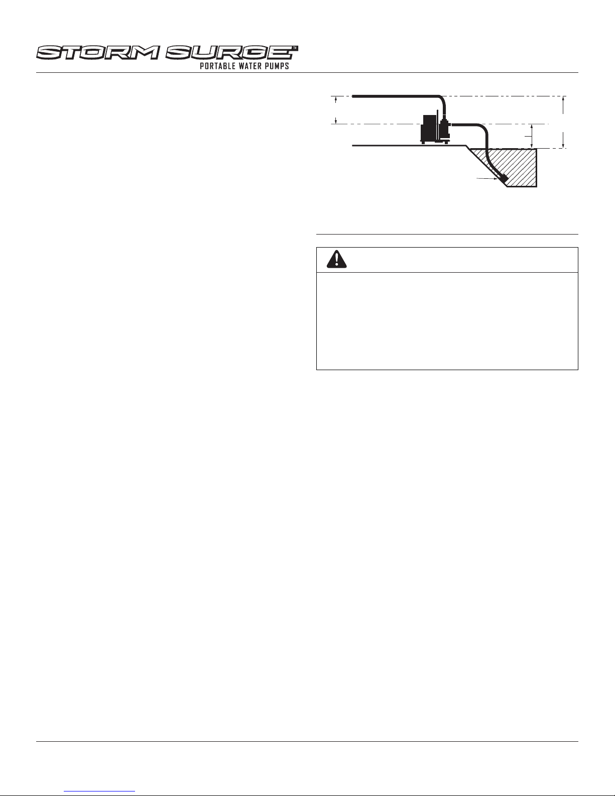
PUMP PLACEMENT
Proper Placement of Pump in Field (SEE FIGURE 5)
NOTE: This pump is designed to be self-priming when
installed and operated as specied below.
• Make sure the pump is positioned on a at, level, and
sturdy surface. The surface must support the weight
of the pump.
• Place the pump as close as possible to the level of the
water to be pumped.
• Use the shortest hoses possible. Hoses that are too
long will decrease the pump ow output and increase
the time to prime the pump.
• When total head increases, the pump output
decreases.
• Discharge head capacity is greater than intake
(suction) head capacity. To achieve the correct
capacities, the pumping height of the intake hose
must be shorter than the pumping height of the
discharge hose.
• The intake hose and strainer must be immersed in
water when the pump is operating.
DISCHARGE
HEAD
SUCTION
LIFT
WATER PUMP
INTAKE
(SUCTION)
HOSE &
STRAINER
FIGURE 5
CAUTION
DO NOT START YOUR WATER PUMP UNIT UNTIL
YOU HAVE READ THE ENGINE PREPARATION
INSTRUCTIONS, AND THE “WARNINGS AND
SAFETY PRECAUTIONS” SECTION IN THIS
MANUAL.
NEVER STORE ENGINE WITH FUEL IN THE TANK
INDOORS. FUEL AND FUEL VAPORS ARE HIGHLY
FLAMMABLE.
TOTAL
HEAD
NOTE: Operation of your Storm Surge™ Water Pump
without an intake strainer basket will void your
warranty. The intake strainer has been designed
to prevent large debris from entering the pump
intake which can cause damage.
• The intake strainer basket should rest on stones or in
a bucket and be secured to prevent movement when
operating.
• Route the discharge hose to a suitable location.
Additional discharge hoses can be used but should be
kept to a minimum to ensure ecient operation.
Water Pump Terminology
Cavitation
• A condition that causes vacuum pockets to form
in the pump. When the air pockets explode under
pressure, pitting to the impeller and volute surfaces
can occur.
Discharge Head
• The total head, including static head and friction
head, on the discharge side of the pump.
Suction Head
• The total head on the suction side of the pump,
including suction lift and friction head.
10
Check for parts online at www.stormsurgepumps.com or call 800-345-6007 M-F 8-5

CAUTION
NEVER ADD FUEL WHEN ENGINE IS RUNNING OR
HOT FROM OPERATION. NEVER FILL THE TANK
INDOORS. DO NOT SMOKE WHEN FILLING FUEL
TANK.
AN ADULT MUST ALWAYS HANDLE AND FILL THE
ENGINE WITH FUEL.
ALWAYS HANDLE FUEL IN A WELL VENTILATED
AREA, OUTDOORS, AWAY FROM FLAMES OR
SPARKS.
DO NOT START ENGINE IF FUEL IS SPILLED. WIPE
OFF EXCESS FUEL AND ALLOW TO DRY. REMOVE
ENGINE FROM AREA TO AVOID SPARKS.
MAKE SURE THE UNIT IS IN A STABLE POSITION
BEFORE PULLING THE STARTER HANDLE.
IF ENGINE FAILS TO START AFTER TRYING
STARTING PROCEDURES, PLEASE CONTACT OUR
CUSTOMER SERVICE DEPARTMENT AT 800345
6007.
STARTER ROPE CAN CAUSE AN UNANTICIPATED
JERK TOWARDS ENGINE. PLEASE FOLLOW
INSTRUCTIONS TO AVOID INJURY.
NEVER LEAVE ENGINE RUNNING WHILE
UNATTENDED. TURN OFF AFTER EVERY USE.
NEVER CARRY PUMP FROM ONE LOCATION TO
ANOTHER WHILE ENGINE IS RUNNING.
NEVER RUN ENGINE INDOORS OR IN ENCLOSED,
POORLY VENTILATED AREAS. ENGINE EXHAUST
CONTAINS CARBON MONOXIDE, AN ODORLESS
AND DEADLY GAS.
KEEP HANDS, FEET, HAIR AND LOOSE CLOTHING
AWAY FROM ANY MOVING PARTS ON ENGINE AND
EQUIPMENT.
DO NOT OPERATE THE PUMP DRY. IF THE PUMP
IS OPERATED DRY THE PUMP SEALS WILL BE
DAMAGED. IF THE PUMP HAS OPERATED DRY,
STOP THE ENGINE IMMEDIATELY. ALLOW THE
PUMP TO COOL AND INSPECT FOR DAMAGE
BEFORE OPERATING AGAIN.
Operator’s Manual
SS14CW Water Pump
Quality
To operate the engine, we recommend using VIPER® brand
4-cycle oil (13235) or an equivalent 10W-30 engine oil to
ensure that the engine operates correctly throughout the life
of the engine. Use straight unleaded premium gasoline, low/
no ethanol blends recommended.
Filling Fuel Tank
1. Shut-o engine and allow engine to completely cool
before relling the fuel tank.
2. Move to a well ventilated area, outdoors, away from
ames and sparks.
3. Clean debris from area around the fuel cap.
4. Loosen fuel cap slowly. Prevent the cap from coming in
contact with dirt or debris.
5. Carefully add fuel without spilling.
6. Do not ll fuel tank completely full, allow space for fuel to
expand.
7. Immediately replace fuel cap and tighten. Wipe o spilled
fuel and allow to dry before starting engine.
Checking and Adding Oil
Be sure the engine is located on a level surface before
checking or relling oil. Proper position for checking oil level
or relling oil is the standard operation position of the pump.
1. Clean around oil ll area.
2. Unscrew dipstick and wipe clean with cloth.
3. Reinsert dipstick (must be fully threaded for accurate
reading).
4. Unscrew and check dipstick. If no oil shows on the
dipstick, rell so that the oil level appears between the low
and high marks on the dipstick. SEE FIGURE 6
5. Change oil if contaminated.
HIGH OIL MARK
LOW OIL MARK
OPERATION
PREPARING ENGINE FOR STARTING
GAS AND OIL
NOTE: Engine is shipped from factory without oil. You must
add engine oil before starting engine. If engine is started
without oil, engine may be damaged beyond repair and will
not be covered by warranty.
Check for parts online at www.stormsurgepumps.com or call 800-345-6007 M-F 8-5 11
FIGURE 6

STARTING AND STOPPING ENGINE
THROTTLE
• Move engine to a well ventilated area, outdoors, to
prevent carbon monoxide poisoning.
• Move to an area away from ames or sparks, to avoid
ignition of vapors if present.
• Remove all debris from air cleaner holes and fuel cap to
ensure proper air ow.
COLD ENGINE START
Starting the engine for rst time or after engine has cooled o
or after running out of fuel.
1. Move choke lever to CHOKE position (SEE FIGURE 7) and
throttle lever to low (Turtle).
NOTE: CHOKE position is dened by moving the choke lever
as far towards the fuel tank as possible.
2. Prime unit until primer hose is lled with fuel.
NOTE: When using the primer bulb, allow the bulb to return
completely to its original position between pushes.
3. Push ON/OFF switch to the ON position.
4. Hold handle bar rmly. Grasp start handle and pull out
slowly until it pulls slightly harder. Without letting starter
handle retract, pull rope with a rapid full arm stroke. Let it
return to its original position slowly. Repeat this step every
time the starter rope is pulled until unit res or runs.
NOTE: If engine fails to start after 5-6 pulls, push primer 1
time and pull starter rope again.
5. After engine starts running, move choke lever to HALF
CHOKE position until unit runs smoothly.
NOTE: Half choke is dened when the choke lever is between
CHOKE and RUN positions. SEE FIGURE 7
6. Move choke lever to RUN position and throttle to desired
speed. SEE FIGURE 7
7. Move throttle lever to high (Rabbit).
NOTE: Full throttle operation ensures that the seal is
lubricated. Do not let unit idle for extended periods of time.
8. To stop engine, push ON/OFF switch to OFF position.
WARM ENGINE START:
1. Move choke lever to CHOKE position. SEE FIGURE 7
2. Continue with Step 3 of Cold Engine Starting.
HOT ENGINE START:
1. Begin with Step 3 of Cold Engine Starting.
2. If engine does not re, refer to Step 1 of Warm Engine
Starting.
Operator’s Manual
SS14CW Water Pump
LEVER
R
U
N
C
H
O
K
E
ON/OFF
SWITCH
PRIMER BULB
FIGURE 7
DO NOT attempt to start engine in the following ways:
• DO NOT use starting uid.
• DO NOT spray ammable liquids or vapors into air cleaner,
carburetor or spark plug chamber.
• DO NOT remove spark plug and attempt to start engine.
Flammable fuel can spray out and ignite from a spark from
spark plug.
TO STOP ENGINE:
Push the ON/OFF switch to the OFF position.
PRIMING THE PUMP
1. Add water to the priming port on the pump. SEE FIGURE
8. Continue to add water until the water level is above the
inlet port of the pump.
2. Install the priming plug. The water in the pump will create
the suction that primes the pump.
NOTE: The slightest air leak in the suction hose will not allow
the pump to prime. The pump may take several minutes to
prime. Do not use this pump for suction lifts over 16 feet.
12
Check for parts online at www.stormsurgepumps.com or call 800-345-6007 M-F 8-5
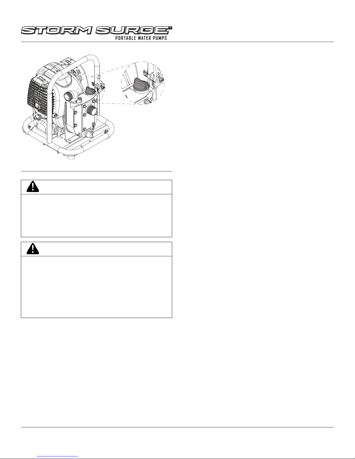
FIGURE 8
IMPORTANT
DO NOT OPERATE THE PUMP DRY. IF THE PUMP
IS OPERATED DRY THE PUMP SEALS WILL BE
DAMAGED. IF THE PUMP HAS OPERATED DRY,
STOP THE ENGINE IMMEDIATELY. ALLOW THE
PUMP TO COOL AND INSPECT FOR DAMAGE
BEFORE OPERATING AGAIN.
CAUTION
CHECK PUMP OFTEN FOR LOOSE NUTS AND
BOLTS. KEEP THESE ITEMS TIGHTENED.
MAINTENANCE AND REPAIR ON THE ENGINE AND
PUMP MUST BE DONE BY AN ADULT.
NEVER STORE ENGINE WITH FUEL IN TANK
INDOORS OR IN ENCLOSED, POORLY VENTILATED
AREAS, WHERE FUEL FUMES MAY REACH AN
OPEN FLAME, SPARK OR PILOT LIGHT.
MAINTENANCE AND STORAGE
Steps for Working on Pump
1. Turn engine switch to OFF.
2. Disconnect the spark plug wire from the spark plug.
3. Securely place the disconnected spark plug wire away
from the spark plug and any metal parts. This must
always be done or arcing may occur between spark plug
wire and metal parts.
4. Replace or repair the part on the pump.
5. Check all parts that were repaired, or removed during
repair, that they are secure and t correctly.
Operator’s Manual
SS14CW Water Pump
NOTE: All repair parts must come from the factory. Never
replace parts that are not specically designed for
the pump.
6. Reconnect the spark plug wire.
Pump Maintenance
Always shut o the engine, allow the engine to cool, and
remove the spark plug before performing any maintenance.
During freezing weather, open the drain port and allow all the
water in the pump to drain. This will prevent damage to the
pump when the water freezes. If the pump will be stored for
a month or more, drain the water from the pump and follow
the engine manufacturer’s recommendations for long-term
storage.
Engine Maintenance
Good maintenance is essential for safe, economical, and
trouble-free operation. It will also help reduce air pollution.
Please read the maintenance schedule and observe these
recommendations to extend the life of your engine.
To help you properly care for your engine, the following
pages include a maintenance schedule, routine inspection
procedures, and simple maintenance procedures using basic
hand tools. Other service tasks that are more dicult, or
require special tools, are best handled by professionals and
are normally performed by a technician or other qualied
mechanic.
Maintenance, replacement or repair of the emissions
control devices and systems may be performed by any
non-road engine repair establishment or individuals.
However, items must be serviced by an authorized dealer
to obtain “no charge” emissions control warranty service.
The maintenance schedule applies to normal operating
conditions. If you operate your engine under unusual
conditions, such as sustained high-load or high-temperature
operation, or use in unusually wet or dusty conditions, consult
your servicing dealer for recommendations applicable to your
individual needs and use.
LUBRICATION
Choose 10W-30 engine oil that meets or surpasses the latest
API service classication.
OIL MAINTENANCE
After the rst ve hours of operating a new Viper® engine the
oil should be replaced, and every 50 hours of operating time
thereafter. The oil should be changed every 25 hours if used
under severe conditions, such as in high temperatures or
under heavy loads. Check oil periodically; DO NOT OVERFILL!
Check for parts online at www.stormsurgepumps.com or call 800-345-6007 M-F 8-5 13
Operator’s Manual
SS14CW Water Pump
CHANGING OIL
Be sure the engine is not operating and is located on a level
surface before checking or relling oil. Engine should be warm
for easy removal of oil. There are many small oil passages in
the engine so wait ve minutes for the oil to accumulate in the
sump for accurate oil level checking.
STEPS FOR CHANGING OIL
1. Flip the ON/OFF switch to the OFF position/
2. Unscrew oil drain screw and empty oil into suitable oil
container. Dispose of oil properly.
3. Reinsert drain screw and remove oil dipstick.
4. Fill with appropriate oil to FULL or top line of dipstick.
(SEE FIGURE 6 ON PAGE 11)
5. Reinsert dipstick or oil ll cap and tighten.
IMPORTANT
PROPER POSITION FOR CHECKING OIL LEVEL OR
REFILLING OIL IS THE STANDARD OPERATION
POSITION. ENSURE THE UNIT IS ON A STURDY,
LEVEL SURFACE. FAILURE TO MAINTAIN THIS
POSITION CAN RESULT IN OVER FILLING THE
ENGINE WITH OIL WHICH WILL IMPAIR THE
ENGINE’S PERFORMANCE.
with warm water and mild soap. Remember to thoroughly
oil the foam lter with 30 or 40 weight motor oil and
squeeze out any excess oil before reinstalling it. Make sure
to press the foam lter evenly into place over the ber
lter to ensure that the foam is fully seated into its sealed
position.
4. Replace the air lter cover by rst connecting the back
latch tabs then swinging the cover, making sure the foam
lter block stays fully seated and in its proper position,
and connect the front latch tab so that it is secured into
place. Make sure to not pinch the ON/OFF switch wires
while replacing the air lter cover.
5. Screw the cover bolt back into place. Check that the cover
is securely attached by puling slightly on the cover. If the
cover doesn’t move when pulled, it is secure.
CAUTION
TO AVOID INJURY OR DEATH, NEVER SIPHON
FUEL BY MOUTH.
IMPORTANT
NEVER TWIST AIR FILTERS WHEN CLEANING.
ALWAYS PRESS.
CARBURETOR
Never tamper with factory setting of the carburetor.
COOLING FINS
Cooling ns, air inlets and linkages must be free from any
debris before each use.
AIR FILTER
Never run engine without air cleaner properly installed. Added
wear and engine failure may occur if air cleaner is not installed
on engine.
Service air cleaner every 3 months or after 20 hours of
operation. Clean lter daily in extremely dusty conditions.
Steps for Replacing and Cleaning Air Filter
1. Before removing the air lter cover, move the chooke lever
to the CHOKE position.
2. To remove air lter cover, unscrew the cover bolt with a
screw driver and gently pop out the front latch tab. The
cover then can be slid o the back latch tabs and away
from the engine. Be careful not to sever or damage the
ON/OFF switch wires while removing the air lter cover.
SEE FIGURE 9
3. Remove the foam lter and ber lter elements. Replace
with a new ber lter and a new oiled foam lter (SEE
FIGURE 10), or clean the original foam and ber lters
Transporting Your Pump
1. After using the pump and before transporting it in a truck
bed, screw the fuel cap on (clockwise) tightly. The fuel
cap will not leak during transporting if fuel cap is tight.
Never transport engine inside an enclosed space within
a vehicle. Fuel or fuel vapors may ignite causing serious
injury or death.
2. If fuel is present in the fuel tank, transport in an open
vehicle in an upright position.
3. If an enclosed vehicle must be used, remove fuel into an
approved red fuel container. DO NOT siphon by mouth.
4. Run engine to use up the fuel in the carburetor and fuel
tank. Always run engine in a well ventilated area. Engine
can run for several minutes due to its ecient design.
5. Wipe away any spilled fuel from engine and pump. Allow
to dry.
6. Fuel cap should be tightly secured before transporting
pump in a vehicle.
Flushing the Pump Housing
1. After use, remove the pump drain plug and allow the
water to drain from the pump housing.
2. Remove the pump primer cap and ush the pump
housing with clean water.
3. After all water has drained from the pump housing,
replace the primer cap and drain plug.
Check for parts online at www.stormsurgepumps.com or call 800-345-6007 M-F 8-5 14

ON/OFF
SWITCH
FIGURE 9
AIR FILTER
COVER
COVER
BOLT
BACK LATCH TABS
FRONT LATCH TAB
FOAM
FILTER
ELEMENT
FILTER
ELEMENT
FIBER
AIR FILTER
COVER
Operator’s Manual
SS14CW Water Pump
TROUBLESHOOTING AND REPAIR
Service Information
At Storm Surge™ we build quality and durability into the
design of our products; but no amount of careful design by us,
and careful maintenance by you, can guarantee a repair-free
life for your machine. Most repairs will be minor, and easily
xed by following the suggestions in the troubleshooting
guides in this section.
This guide will help you pinpoint the causes of common
problems and identify remedies.
For more complicated repairs, contact Storm Surge™ for an
authorized service center in your area.
We will always be glad to answer any questions you have, or
help you nd suitable assistance. To order parts or inquire
about warranty, call, write or e-mail us using the contact
information found in this section.
Ordering Replacement Parts
For your convenience a parts breakdown is included toward
teh end of the manual.
To order parts visit www.stormsurgepumps.com or call 1-800345-6007.
For other general questions, you can e-mail us at info@
ardisam.com.
Please include the following information with your order:
1. Part numbers
2. Part description
3. Quantity
4. Model number and serial number
FIGURE 10
Long-Term Storage
If your pump will not be used for more than three months,
prepare it for long-term storage.
Steps for Long-Term Storage
1. Mix an appropriate amount of fuel stabilizer to fresh
gasoline, in the ratio recommended on the stabilizer
packaging. Run the engine for ve minutes to distribute
the stabilizer mixture throughout the fuel system. This will
prevent gum, varnish and corrosion build up in your fuel
system during long-term storage for up to 12 months.
2. Store pump in the standard operation position.
3. Remove all debris from pump and engine.
Check for parts online at www.stormsurgepumps.com or call 800-345-6007 M-F 8-5 15

Operator’s Manual
SS14CW Water Pump
Table 1. Engine Troubleshooting Guide
PROBLEM POSSIBLE CAUSE REMEDY/ACTION
Engine will not start 1. Power switch o 1. Flip switch to ON position
2. Spark plug wire disconnected 2. Connect spark plug wire to spark plug
3. Out of fuel 3. Refuel
4. Spark plug wet, faulty, or improperly
4. Clean, replace , or gap spark plug
gapped
5. Fuel line hose not positioned in
5. Push fuel line down into fuel in fuel tank
bottom of fuel tank
Engine runs rough, oods
during operation
1. Dirty air lter 1. Clean or replace air lter
2. Choke partially engaged 2. Turn o choke
3. Carburetor out of adjustment 3. Call factory
Engine is hard to start 1. Stale fuel 1. Drain old fuel and replace with fresh. Use fuel
stabilizer at end of season.
2. Spark plug wire loose 2. Make sure spark wire is securely attached to
spark plug
3. Dirty carburetor 3. Clean carburetor, use fuel stabilizer, new gas can
Engine misses or lacks power 1. Clogged fuel tank 1. Remove and clean fuel tank
2. Clogged air lter 2. Clean or replace air lter
3. Carburetor out of adjustment or bad 3. Call factory
4. Spark plug wet, faulty or improperly
4. Clean, replace or gap spark plug
gapped
Engine runs, but has no power 1. Choke on 1. Turn o choke after engine is running
2. Carburetor out of adjustment or bad 2. Call factory
3. Fuel cap not venting 3. Replace fuel cap
Engine runs, then quits 1. Plugged fuel lter 1. Clean or replace fuel lter
2. Carburetor out of adjustment or bad 2. Call factory
3. Fuel cap not venting 3. Clean or replace fuel cap
Engine revs too high 1. Carburetor out of adjustment 1. Call factory
2. Low fuel in tank 2. Add fuel to tank
Contact Storm Surge™ customer service at 800-345-6007 if additional assistance is needed.
Only use approved Storm Surge™ spare parts.
Check for parts online at www.stormsurgepumps.com or call 800-345-6007 M-F 8-5 16

Table 2. Pump Troubleshooting Guide: No Pump Output
PROBLEM: No Pump Output POSSIBLE CAUSE REMEDY/ACTION
Check Pump Housing 1. Pump not primed 1. Prime the pump.
1. Hose collapsed, cut or punctured. 1. Replace Hose
2. Strainer not fully under water. 2. Make sure hose end and strainer basket is
completely under water.
Check Intake (Suction) Hose
3. Air leak at connector. 3. Replace sealing gasket if damaged or missing.
Use Teon pipe thread tape on all threaded
coupling surfaces.
4. Strainer basket clogged 4. Clean debris from strainer basket.
Operator’s Manual
SS14CW Water Pump
Measure suction and discharge
1. Excessive head 1. Relocate pump and hoses to reduce head.
head SEE FIGURE 5 “PUMP
PLACEMENT”
Check Engine Refer to Table 1. (Engine Troubleshooting Guide.)
Contact Storm Surge™ customer service at 800-345-6007 if additional assistance is needed.
Table 3. Pump Troubleshooting Guide: Low Pump Output
PROBLEM: Low Pump Output POSSIBLE CAUSE REMEDY/ACTION
1. Hose collapsed, cut, or punctured.
1. Replace Hose
Hose too long or too small a
diameter.
2. Strainer not fully under water. 2. Make sure hose end and strainer basket is
Check Intake (Suction) Hose
completely under water.
3. Air leak at connector. 3. Replace sealing gasket if damaged or missing.
Use Teon pipe thread tape on all threaded
coupling surfaces.
4. Strainer basket clogged 4. Clean debris from strainer basket.
Check Discharge Hose 1. Hose damaged, cut, or punctured.
Hose too long or too small a
diameter.
Measure suction and discharge
1. Excessive head 1. Relocate pump and hoses to reduce head.
head SEE FIGURE 5 “PUMP
PLACEMENT”
Check Engine Refer to Table 1. (Engine Troubleshooting Guide.)
Contact Storm Surge™ customer service at 800-345-6007 if additional assistance is needed.
Check for parts online at www.stormsurgepumps.com or call 800-345-6007 M-F 8-5 17
1. Replace Discharge Hose

ILLUSTRATED PARTS BREAKDOWN PUMP & FRAME
9
10
8
11
Operator’s Manual
SS14CW Water Pump
1
15
14,
13,
19
12,
19
12,
13,
19
19
14,
19
19
7
6
16
5
17
18
1
2
3
4
18
Check for parts online at www.stormsurgepumps.com or call 800-345-6007 M-F 8-5

1, 15
30
15, 27
15, 28, 34
15, 29
15, 29, 30,
15, 31,
34
Operator’s Manual
SS14CW Water Pump
15, 32
15, 33
1, 15
15,
20
1,
15
15,
21,
34
15,
22,
34
15,
23
15,
24
15,
25,
34
ITEM # PART # DESCRIPTION QT Y.
1 67028 BOLT M6 X 1.0 X 16 HEX 19
2 300336 BOLT M6 X 1.0 X 10 HEX 2
3 42127 FOOT RUBBER 4
4 42131 BOLT M6 X 1.0 X 14 PHILIPS 4
5 22507 FRAME PUMP MOUNT 1
6 14109 NUT M6 X 1.0 HEX NYLOC 4
7 22514 THROTTLE CONTROL ASSEMBLY 1
8 42119 SPACER ENGINE MOUNT 2
9** ENGINE 4CYCLE 40CC 1” PUMP 1
10 42102 ADAPTER PLATE 1” PUMP 1
11 42101 PUMP MOUNT BRACKET 1
12* WING NUT HOSE ADAPTER 1” 2
13* BARBED NIPPLE 1” PUMP 2
14* NIPPLE SEAL 1” PUMP 2
15 15328 PUMP SEMI TRASH 1” NPSH 1
16 42137 STRAINER 1” WATERPUMP 1
17 48166 GARDEN HOSE ADAPTER 1” 2
15, 26
ITEM # PART # DESCRIPTION QTY.
15,
29,
15,
29
18 42135 HOSE CLAMP 1” WATERPUMP 3
19 15521 KIT 1” BARBED HOSE ADAPTER 2
20* IMPELLER HOUSING COVER 1
21* MECHANICAL SEAL 1” PUMP 1
22* CERAMIC SEAL 1” PUMP 1
23 42134 IMPELLER 1 “ PUMP 1
24 42122 VOLUTE HOUSING 1” PUMP 1
25* RUBBER GASKET 1” PUMP 1
26* HOUSING 1” PUMP 1
27* OUTLET PORT 1” NPSH 1
28* ORING SEAL 1.30 X 1/8 INCH 1
29 15195 CAP & ORING FILL/DRAIN PORT 2
30* ORING SEAL FILL/DRAIN PORTS 2
31* CHECK VALVE GASKET 1” PUMP 1
32* HOUSING FRONT COVER 1
33* BOLT M6 X 1.0 X 50 HEX HEAD 6
34 15520 KIT GASKETS & SEALS 1” PUMP 1
*Available as kit only.
**Engine not available to purchase. Please replace pump (PN 20198) if engine is irrepairable.
Check for parts online at www.stormsurgepumps.com or call 800-345-6007 M-F 8-5 19

ILLUSTRATED PARTS BREAKDOWN ENGINE
1, 49
Operator’s Manual
SS14CW Water Pump
38, 50
35, 50
24, 52
25, 52
57
26, 52,
57
27, 54,
22
2
23, 54
15, 53,
21
2
57
31, 47,
28
29
50
30, 47,
39
50
14, 55
40, 56
41, 56
34, 50
50
33, 47,
50
32, 47,
43
42
36, 50
44
37, 50
45
20
17, 51
2, 53
20, 51
19, 51
12, 55
8, 48
7, 49
6, 49
5, 49
4, 49
3, 49
2, 49
16, 53
17, 51
17, 51
14, 55
18, 51
13, 55
11, 46
10, 46
2, 46
57
9, 48
Check for parts online at www.stormsurgepumps.com or call 800-345-6007 M-F 8-5

ENGINE PARTS LIST
Operator’s Manual
SS14CW Water Pump
ITEM # PART # DESCRIPTION QTY.
1 13553 ON/OFF SWITCH 1
2 10887 BOLT M5 X 0.8 X 16 W/WASHER 11
3 17053 AIR FILTER COVER SWITCH HOLE 1
4 13198 AIR FILTER FOAM 1
5 17078 AIR FILTER FIBER 1
6 400020 NUT M5 X 0.8 HEX TOPLOCK 2
7* INTAKE BASE ASSEMBLY 1
8* CARBURETOR 40CC 4CYCLE 1
9* CARBURETOR GASKET 1
10* CARBURETOR INSULATOR 1
11 13332 BOLT M5 X 0.8 X 55 2
12* CRANKCASE BREATHER HOSE 1
13* VALVE COVER BREATHER HOSE 1
14* HOSE CLAMP 13.5MM 2
15* GASKET VALVE COVER 1
16* VALVE COVER 1
17 300471 BOLT M5 X 0.8 X 12 W/WASHER 3
18* ENGINE SHROUD PLUG ACCESS 1
19* CAP ENGINE SHROUD 1
20* SCREW ENGINE SHROUD 1
21 13244 RECOIL CLUTCH 1
22 13342 RECOIL ASSEMBLY 1
23* OIL CAP 1
24 13181 BOLT M5 X 0.8 X 50MM 2
25* MUFFLER ASSEMBLY 1
26* MUFFLER HEAT SHIELD 1
27* ORING 15.6 X 19.16 X 1.78 MM 1
28 13449 BOLT M6 X 1.0 X 8 X 12 MM 1
29 13320 WASHER M6 X 10 X 1 MM 1
30* FUEL LINE 245MM 1
31 17992 FUEL FILTER ALUMINUM CORE 1
ITEM # PART # DESCRIPTION QTY.
32* GROMMET FUEL TANK 1
33* FUEL LINE 195 MM 1
34 19236 GAS CAP 4CYCLE EPA SELF VENT 1
35* RUBBER TANK HOLDER TOP 1
36* GAS TANK 40CC VERTICAL 1
37* RUBBER TANK HOLDER LEFT 1
38* RUBBER TANK HOLDER RIGHT 1
39 13243 SPARK PLUG NGK CMR6A 1
40* IGNITION COIL 1
41 13325 BOLT M4 X 0.7 X 20 W/WASHER 2
42 13241 FLYWHEEL 1
43 42141 OUTPUT SHAFT 1
44 13239 MOUNT RING AND SHROUD 1
W1200123
45 BOLT M5 X 0.8 X 16 3
ENGINE PART KITS LIST
ITEM # PART # DESCRIPTION QTY.
46 13390 CARBURETOR BRACKET KIT 1
47 13308 FUEL LINES KIT 1
48 13329 CARBURETOR KIT 1
49 22559 AIR FILTER KIT 1
50 22558 FUEL TANK KIT WITH FUEL LINE 1
51 18497 ENGINE SHROUD KIT 1
52 13391 MUFFLER KIT 1
53 13298 VALVE COVER KIT 1
54 13393 OIL CAP KIT WITH ORING 1
55 13394 BREATHER HOSES KIT 1
56 13400 IGNITION COIL KIT 1
57 13066 GASKETS KIT 1
58 13235 OIL VIPER 4CYCLE 10W30 1
59 15313 SPARK PLUG WRENCH 1
*Available as kit only.
Check for parts online at www.stormsurgepumps.com or call 800-345-6007 M-F 8-5 21

Operator’s Manual
SS14CW Water Pump
WARRANTY TERMS AND CONDITIONS
PRODUCT WARRANTY: 2YEAR LIMITED WARRANTY
Ardisam, Inc. (Ardisam), a manufacturing company, warrants this product to be free from defects in the material or workmanship
for a period of two years from the date of purchase. If there is insucient evidence of the purchase date, the eective date of this
warranty will begin on the pump’s date of manufacture. During the two-year warranty of this product, Ardisam will furnish, at their
discretion, parts and labor to correct any defect caused by faulty material or workmanship. Ardisam reserves the right to inspect
any incoming units returned under warranty to determine if the warranty applies before performing any warranty related work
(including parts and components). Any unit used in a commercial application is covered for a period of 90 days after purchase.
This warranty applies to the original owner with a proof of purchase and is not transferable. For the warranty to be valid, the
product must be registered online, or the warranty card must be lled out and received by Ardisam, within 30 days of purchase.
Warranty Exclusions
This warranty excludes:
• Wear items such as lter elements, O-rings, impeller, and seals.
• Accessory parts such as hoses, intake strainer, and connectors.
• Running the pump dry (without water).
• Running the pump without the included intake strainer properly attached.
• Using the pump to move uids other than water ranging from 32° - 150° F.
• Using the pump for a purpose other than which it was designed and manufactured.
• Using the pump in violation of local codes, ordinances and good trade practices.
For replacement parts, phone 800-345-6007.
*These warranties apply only to products which have not been subjected to negligent use, abuse, misuse (including the use
of this pump in place of your well or water utility), overload, improper installation, alteration, accident, acts of God (or other
events beyond Ardisam’s control), unauthorized parts, failure to use proper fuel and oil, or if repairs have been performed at a
non-authorized service facility. These warranties shall not cover damage from normal wear and tear, normal maintenance parts
and services, lightning; nor improper installation, operation, storage, or maintenance; nor operating the equipment above
recommended maximums as stated in this manual and the accompanying engine manual. These warranties supersede all other
warranties either expressed or implied and all other obligations or liabilities on the part of Ardisam. Ardisam, does not assume,
and does not authorize any other person to assume for Ardisam, any liability in connection with the sale of Ardisam products. To
be at “No Charge,” warranty work must be sent directly to and performed by Ardisam or an Ardisam Authorized Warranty
Service Facility. To obtain warranty service and/or replacement instructions, contact the Ardisam Customer Service Department
at 800-345-6007. Ardisam will cover the cost of shipping only for purchasers located more than 100 miles from an Ardisam
Authorized Warranty Service Facility if it is determined that warranted repair is indeed necessary. If you choose to ship your
product to Ardisam for warranty repair, you must rst have prior approval from Ardisam by calling the Ardisam Customer Service
Department for a return material authorization number (RMA#). Under these circumstances, all items must be shipped prepaid.
Ardisam will at no charge, repair or replace, at the discretion of Ardisam, any defective part which falls under the conditions stated
above. Ardisam retains the right to change models, specications and price without notice. Ardisam shall not be obligated to ship
any repair or replacement product to any location outside of the United States of America or Canada. Some states and countries
do not allow the limitations on how long an implied warranty lasts, or the exclusion or limitation of incidental or consequential
damages, so the above limitation may not apply to you. This warranty gives you specic legal rights, and you may also have other
rights which vary from state to state and country to country.
22
Check for parts online at www.stormsurgepumps.com or call 800-345-6007 M-F 8-5

MAINTENANCE SCHEDULE
Operator’s Manual
SS14CW Water Pump
Maintenance Item
Clean Engine and Check Bolts & Nuts X
Engine Oil Check X
(See Lubrication Section) Change* (initial 5 hours) X
Engine Oil Check X X
See Air Filter Section) Clean** (20 hours)
Replace X
Spark Plug (0.6mm) Check/Adjust X
(See Spark Plug Section) Replace X
Fuel Filter Clean*** X
(See Fuel Filter Section) Replace X
Fuel Tank Clean*** X
Valve Clearance Intake: 0.15mm (0.006”
Exhaust: 0.20mm (0.008”)
* Perform initial oil change after rst 5 hours of operation, then every 50 hours or every season
** Service more frequently under dusty conditions
*** These items should only be performed by a mechanically procient person or by the servicing dealer
Check/Adjust X
Every 8 hours
(daily)
Every 50 hours
or seasonally
Every 100 hours
or seasonally
Each year
23
Check for parts online at www.stormsurgepumps.com or call 800-345-6007 M-F 8-5

Operator’s Manual
SS14CW Water Pump
FEDERAL EMISSION CONTROL WARRANTY STATEMENT
YOUR WARRANTY RIGHTS AND OBLIGATIONS
The United States Environmental Protection Agency (EPA), together
with Ardisam, Inc. (Ardisam), are pleased to explain the Emission
Control System Warranty on your small o-road engine (SORE). New
small o-road engines must be designed, built and equipped to meet
stringent anti-smog standards the federal government. Ardisam will
warrant the emission control system on your engine for the periods
of time listed below provided there has been no abuse, neglect,
modication or improper maintenance of your engine.
The emission control system includes all components whose failure
would increase the emissions of any regulated pollutant. These
components are listed in the emission-related parts list located in a
subsequent section of this emissions warranty statement. Ardisam
will repair your engine at no cost to you for diagnosis, replacement
parts and labor, should a warrantable condition occur.
MANUFACTURER’S WARRANTY COVERAGE:
The emission control system is warranted for two years. If, during such
warranty period, any emission-related part on your engine is found to
be defective in materials or workmanship, repairs or replacement will
be performed by a Ardisam Authorized Warranty Service Facility.
PURCHASER’S/OWNER’S WARRANTY RESPONSIBILITIES:
As the SORE purchaser/owner, you are responsible for the completion
of all required maintenance as listed in your factory supplied
Manual(s). For warranty purposes, Ardisam recommends that you
retain all receipts covering maintenance on your SORE. However,
Ardisam cannot deny warranty solely because of the lack of receipts
or for your failure to ensure the completion of all scheduled
maintenance.
As the SORE purchaser/owner, you should, however, be aware that
Ardisam may deny any and/or all warranty coverage or responsibility
if your SORE or a part/component thereof, has failed due to abuse,
neglect, improper maintenance or modications, or the use of
counterfeit and/or “grey market” parts not made, supplied or
approved by Ardisam.
You are responsible for presenting your SORE to an Ardisam
Authorized Warranty Service Facility as soon as a problem occurs.
The warranty repairs should be completed in a reasonable amount of
time, not to exceed 30 days.
Warranty service can be arranged by contacting either your selling
dealer or a Ardisam Authorized Warranty Service Facility. To locate the
Ardisam Authorized Warranty Service Facility nearest you, call our free
number:
800-345-6007
IMPORTANT NOTE: This warranty statement explains your rights
and obligations under the Emission Control System Warranty
(ECS Warranty), which is provided to you by Ardisam pursuant to
federal law. See also the Ardisam “Product Warranty” (non-emission
warranties), which is enclosed herewith on a separate sheet or
located in additional materials accompanying this product. The ECS
Warranty applies only to the emission control system of your new
engine. If there is any conict in terms between the ECS Warranty
and the Ardisam Warranty, the ECS Warranty shall apply except in
circumstances where the Ardisam Warranty may provide a longer
warranty period. Both the ECS Warranty and the Ardisam Warranty
describe important rights and obligations with respect to your new
engine.
Warranty service can be performed only by an Ardisam Authorized
Warranty Service Facility. When requesting warranty service, evidence
must be presented showing the date of the sale to the original
purchaser/owner. Ardisam will not be responsible for any and/or all
damages or losses incurred while the engine is being transported/
shipped for inspection or warranty repairs.
IF YOU HAVE ANY QUESTIONS REGARDING YOUR WARRANTY RIGHTS
AND RESPONSIBILITIES, YOU SHOULD CONTACT ARDISAM AT THE
FOLLOWING ADDRESS:
Ardisam, Inc.
1160 Eighth Avenue; P.O. Box 666
Cumberland, Wisconsin 54829
800-345-6007 · Fax (715) 822-4180
E-mail: info@ardisam.com
II. EMISSION CONTROL SYSTEM WARRANTY
Emission Control System Warranty (ECS Warranty) for equipment
using small o-road engines:
(a) Applicability: This warranty shall apply to equipment that uses
small o-road engines. The ECS Warranty Period shall begin on
the date the new engine or equipment is purchased by/delivered
to its original, end-use purchaser/owner and shall continue for 24
consecutive months thereafter.
(b) General Emissions Warranty Coverage: Ardisam warrants to the
original, end-use purchaser/owner of the new engine or equipment
and to each subsequent purchaser/owner that each of its engines is...
(1) Designed, built and equipped so as to conform with all
applicable regulations adopted by the EPA pursuant to their
respective authority, and
(2) Free from defects in materials and workmanship which, at
any time during the ECS Warranty Period, may cause a warranted
emissions-related part to fail to be identical in all material respects
to the part as described in the engine manufacturer’s application
for certication.
The ECS Warranty only pertains to emissions-related parts on your
engine, as follows:
(1) Any warranted, emissions-related parts that are not scheduled
24
Check for parts online at www.stormsurgepumps.com or call 800-345-6007 M-F 8-5

Operator’s Manual
SS14CW Water Pump
for replacement as required maintenance in the Maintenance
Schedule (located in the section of the Manual(s) pertaining to
maintenance) shall be warranted for the ECS Warranty Period. If any
such part fails during the ECS Warranty Period, it shall be repaired
or replaced by Ardisam according to Subsection (4) below. Any
such part repaired or replaced under the ECS Warranty shall be
warranted for the remainder of the ECS Warranty Period.
(2) Any warranted, emissions-related part that is scheduled only
for regular inspection as specied in the Maintenance Schedule
(located in the section of the Manual(s) pertaining to maintenance)
shall be warranted for the ECS Warranty Period. A statement in such
written instructions to the eect of “repair or replace as necessary”
shall not reduce the ECS Warranty Period. Any such part repaired
or replaced under the ECS Warranty shall be warranted for the
remainder of the ECS Warranty Period.
(3) Any warranted, emissions-related part that is scheduled
for replacement as required maintenance in the Maintenance
Schedule (located in the section of the Manual(s) pertaining to
maintenance) shall be warranted for the period of time prior to the
rst scheduled replacement point for that part. If the part fails prior
to the rst scheduled replacement, the part shall be repaired or
replaced by Ardisam according to Subsection (4) below. Any such
emissions-related part repaired or replaced under the ECS Warranty
shall be warranted for the remainder of the ECS Warranty Period
prior to the rst scheduled replacement point for such emissionsrelated part.
(4) Repair or replacement of any warranted, emissions-related part
under this ECS Warranty shall be performed at no charge to the
owner at a Ardisam Authorized Warranty Service Facility.
(5) When the engine is inspected by a Ardisam Authorized Warranty
Service Facility, the owner shall not be held responsible for
diagnostic costs if the repair is deemed warrantable.
(6) Ardisam shall be liable for damages to other original engine
components or approved modications proximately caused by a
failure under warranty of any emission-related part covered by the
ECS Warranty.
(7) Throughout the ECS Warranty Period, Ardisam shall maintain a
supply of warranted emission-related parts sucient to meet the
expected demand for such emission-related parts.
(8) Any Ardisam authorized and approved emission-related
replacement part may be used in the performance of any ECS
Warranty maintenance or repairs and will be provided without
charge to the purchaser/owner. Such use shall not reduce Ardisam’s
ECS Warranty obligations.
(9) Unapproved, add-on, modied, counterfeit and/or “grey market”
parts may not be used to modify or repair a Ardisam engine. Such
use voids this ECS Warranty and shall be sucient grounds for
disallowing an ECS Warranty claim. Ardisam shall not be held liable
hereunder for failures of any warranted parts of a Ardisam engine
caused by the use of such an unapproved, add-on, modied,
counterfeit and/or “grey market” part.
EMISSION-RELATED PARTS INCLUDE THE FOLLOWING
(IF EQUIPPED):
(1) Fuel Metering System
(i) Carburetor and internal parts (and/or pressure regulator or
fuel injection system).
(ii) Air/fuel ratio feedback and control system.
(iii) Cold start enrichment system.
(iv) Fuel Tank.
(2) Air Induction System
(i) Controlled hot air intake system.
(ii) Intake manifold.
(iii) Air lter.
(3) Ignition System
(i) Spark Plugs.
(ii) Magneto or electronic ignition system.
(iii) Spark advance/retard system.
(4) Exhaust Gas Recirculation (EGR) System
(i) EGR valve body, and carburetor spacer if applicable.
(ii) EGR rate feedback and control system.
(5) Air Injection System
(i) Air pump or pulse valve.
(ii) Valves aecting distribution of ow.
(iii) Distribution manifold.
(6) Catalyst or Thermal Reactor System
(i) Catalytic converter.
(ii) Thermal reactor.
(iii) Exhaust manifold.
(7) Particulate Controls
(i) Traps, lters, precipitators, and any other device used to
capture particulate emissions.
(8) Miscellaneous Items Used in Above Systems
(i) Electronic controls.
(ii) Vacuum, temperature, and time sensitive valves and
switches.
(iii) Hoses, belts, connectors, and assemblies.
Check for parts online at www.stormsurgepumps.com or call 800-345-6007 M-F 8-5 25

NOTES
Operator’s Manual
SS14CW Water Pump
26
Check for parts online at www.stormsurgepumps.com or call 800-345-6007 M-F 8-5

NOTES
Operator’s Manual
SS14CW Water Pump
Check for parts online at www.stormsurgepumps.com or call 800-345-6007 M-F 8-5 27

All weights, specications and features are approximate and are subject to change without notice. Due to continuous product improvements, product images may not be exact. Items used for props not included.
Some assembly may be required.
Check for parts online at www.stormsurgepumps.com or call 800-345-6007 M-F 8-5
Ardisam, Inc.
1160 8th Avenue, PO Box 666
Cumberland, WI 54829
800-345-6007 | Fax 715-822-2223
E-mail: info@ardisam.com
 Loading...