

Page 1
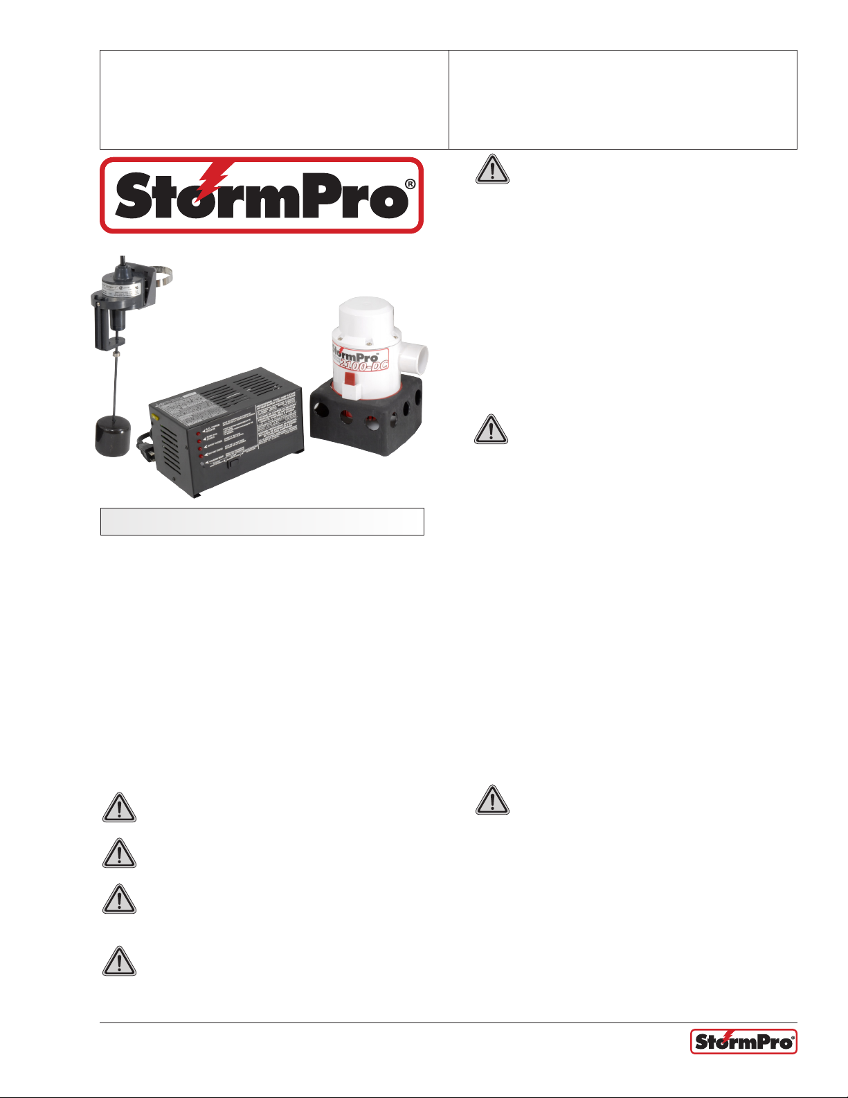
StormPro® 2100DC
Heavy Duty 12V DC Pump
OPERATION MANUAL
Dated: 03/15/2013
Document Name: StormPro_2100DC_OM
Page 1 of 8
WARNING: Electrical shock hazard. This unit
has not been evaluated for use outdoors.
Never operate StormPro® 2100DC outdoors.
Never operate StormPro® 2100DC with battery
enclosure open.
Never operate StormPro® 2100DC in a wet location.
Never operate StormPro® 2100DC in a location where
liquid or moisture will come in contact with, splash on,
or drip on unit.
Do not insert or allow foreign objects to enter any
ventilation or exhaust opening as this may cause
electric shock, and/or a re hazard.
WARNING: Risk of electrical shock. In the
event of a short circuit, grounding reduces
the risk of shock by providing an escape wire for the
electrical current. The StormPro® 2100DC must be
properly grounded.
Safety InStructIonS
Read and save these instructions. This manual
contains important instructions. Failure to heed safety
instructions and warnings could result in injury or
death.
Read all the instructions before installing or using
the StormPro® 2100DC. Always disconnect batteries
and disconnect StormPro® 2100DC from the AC
power source before storing, handling, or making any
adjustments to the unit.
Use StormPro® 2100DC only as described in this
manual. Any other use not recommended by the
manufacturer may cause re, electric shock, or injury
to persons.
CAUTION: Do not sit or stand on StormPro®
2100DC. Keep children away.
CAUTION: Do not place objects on Stormpro
2100-DC or allow vents to become blocked.
CAUTION: Do not smoke, use sparkable
electrical devices, or open ame when
working on this unit!
CAUTION: Do not install StormPro® 2100DC
in locations classied as hazardous per
N.E.C., ANSIINFPA 70 - 1984.
The StormPro® 2100DC is equipped with a cord
having a grounding wire with an appropriate
grounding plug. The plug must be used with an outlet
that has been installed and grounded in accordance
with all local codes and ordinances. The outlet must
be the same conguration as the plug. Where a two-
prong wall outlet is encountered, it must be replaced;
contact a qualied electrician. To reduce the risk of
electric shock, the grounding plug must not be cut off
the plug. Do not use the three-prong plug with a twoprong adapter. Do not attempt to defeat this safety
feature.
Use the StormPro® 2100DC only with adequate wiring
that is up to code. Connect to properly grounded
outlets only.
WARNING: Risk of electrical shock. The
StormPro® 2100DC is capable of and intended
to generate electrical current when unplugged from the
wall outlet or when the AC power is shut off.
Because the StormPro® 2100DC uses batteries to
generate 120 volts of AC current, both the batteries
and the power cord must be disconnected to neutralize
the StormPro® 2100DC . Failure to disconnect both the
batteries and the power cord could result in electrical
shock sufcient to cause injury or death.
Register your product at www.sumpro.com
Page 2
StormPro® 2100DC
Heavy Duty 12V DC Pump
OPERATION MANUAL
Dated: 03/15/2013
Document Name: StormPro_2100DC_OM
Page 2 of 8
Battery PrecautIonS
WARNING: Important safety instructions.
Save these instructions.
Servicing of batteries should be performed or
supervised by personnel knowledgeable of batteries
and the required precautions. Keep unauthorized
personnel away from batteries.
When replacing batteries, use only models
conforming to Battery Council International (BCI) 27
DC specications for Group 27 deep cycle marine
batteries. At the time of this publication, the following
model batteries are recommended. At the time of
purchase, verify that these models, or any other
model, conform to Battery Council International (BCI)
27DC specications for Group 27 deep cycle marine
batteries:
Die Hard Model 27524
Exide Model NC-27
Interstate Model SRM-27
Metropolitan Model 27T-36
Metropolitan Model MT120
Metropolitan AGM Model LW20104
NAPA Model 8270
CAUTION: Do not dispose of batteries in a
re. The batteries may explode.
CAUTION: Do not open or mutilate the
batteries. Released electrolyte is harmful to
the skin and eyes. It may be toxic.
2. If electrolyte contacts the skin, wash it off
immediately.
3. If electrolyte contacts the eyes, ush thoroughly
and immediately with water. Seek medical
attention.
4. Spilled electrolyte should be washed down with
a suitable acid neutralizing agent. A common
practice is to use a solution of approximately
one pound (500 grams) bicarbonate of soda to
approximately one gallon (4 liters) of water. The
bicarbonate of soda solution can be added until
the evidence of reaction (foaming) has ceased.
The resulting liquid should be ushed with
water and the area dried.
CAUTION: Lead acid batteries can present
a risk of re because they generate oxygen
and hydrogen gas. The following procedures should
be followed.
1. Do not smoke when near batteries
2. Do not cause ame or spark in battery area.
3. Discharge static electricity from body before
touching batteries by rst touching a grounded
metal surface.
4. See battery manufacturers’ installation manual
for additional installation maintenance, and
safety instructions.
CAUTION: A battery can present a risk of
electrical shock and high short circuit current.
The following precautions should be observed when
working on batteries.
1. Remove watches, rings, or other metal objects.
2. Use tools with insulated handles.
3. Do not lay tools or metal objects on top of
batteries.
4. Wear safety goggles and a face shield.
CAUTION: The electrolyte is a dilute sulfuric
acid that is harmful to the skin and eyes. It
is electrically conductive and corrosive. The following
procedures should be observed:
1. Wear full eye protection and clothing.
Register your product at www.sumpro.com
toolS & MaterIalS needed
A pipe wrench, pliers, adjustable wrench, pipe
cutter, and a screwdriver will be needed. PVC Pipe,
appropriate PVC tting, PVC glue and primer, non
restrictive 1 1/2” check valve, and a tape measure.
PuMP InStallatIon
1. Use PVC glue to fasten the pumps 90 degree
elbow onto the pumps discharge pipe in an
upright position so the discharge is going
straight up. Use PVC glue to secure the elbow
into place.
2. Screw in the 1 1/8” PVC male adapter tting
into the 90 degree elbow on the pump.
Page 3
StormPro® 2100DC
Heavy Duty 12V DC Pump
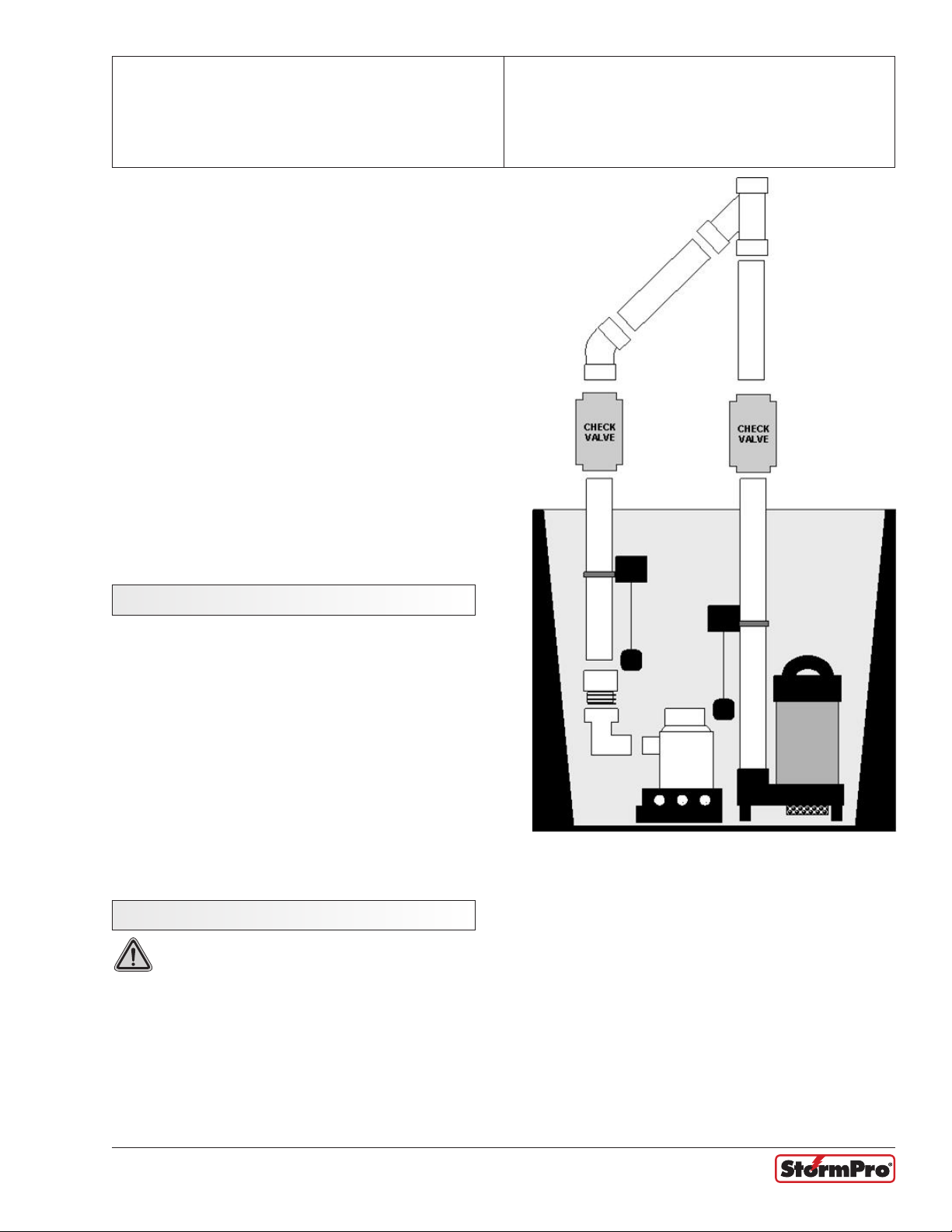
3. Place the pump into the pump base.
4. Place the pump into the basin in a suitable
position next to the primary pump and away
from the drain tile if possible.
5. Begin to rough in your PVC piping, If you are
using a single discharge pipe for both pumps,
make sure your PVC Y or 90 degree connection
is above the primary check valve. Do not glue
any ttings at this point.
6. Make sure to include a separate 1 1/2” check
valve for the backup pumps discharge pipe. Do
not use spring loaded or any type resistance
check valve.
7. Once all of your PVC piping is roughed in and
all pipe connections t ush begin to glue the
piping together starting from the pump up. Use
only PVC cement and primer.
OPERATION MANUAL
Dated: 03/15/2013
Document Name: StormPro_2100DC_OM
Page 3 of 8
float SwItch InStallatIon
1. The backup oat switches turn ON point must
be above the primary pump oat switches ON
point and below the top of the basin.
2. Once the backup pump is installed properly
attach the backup oat switch by tightening the
switch clamp securely to the backup pumps
discharge pipe.
3. Make sure that the oat ball on the backup
switch will not get caught or hung up on the
primary pump or any other object that will
restrict the switch from turning on.
4.
charger unIt InStallatIon
WARNING: Be sure that the charger unit
is not plugged into the wall outlet before
connecting the terminals
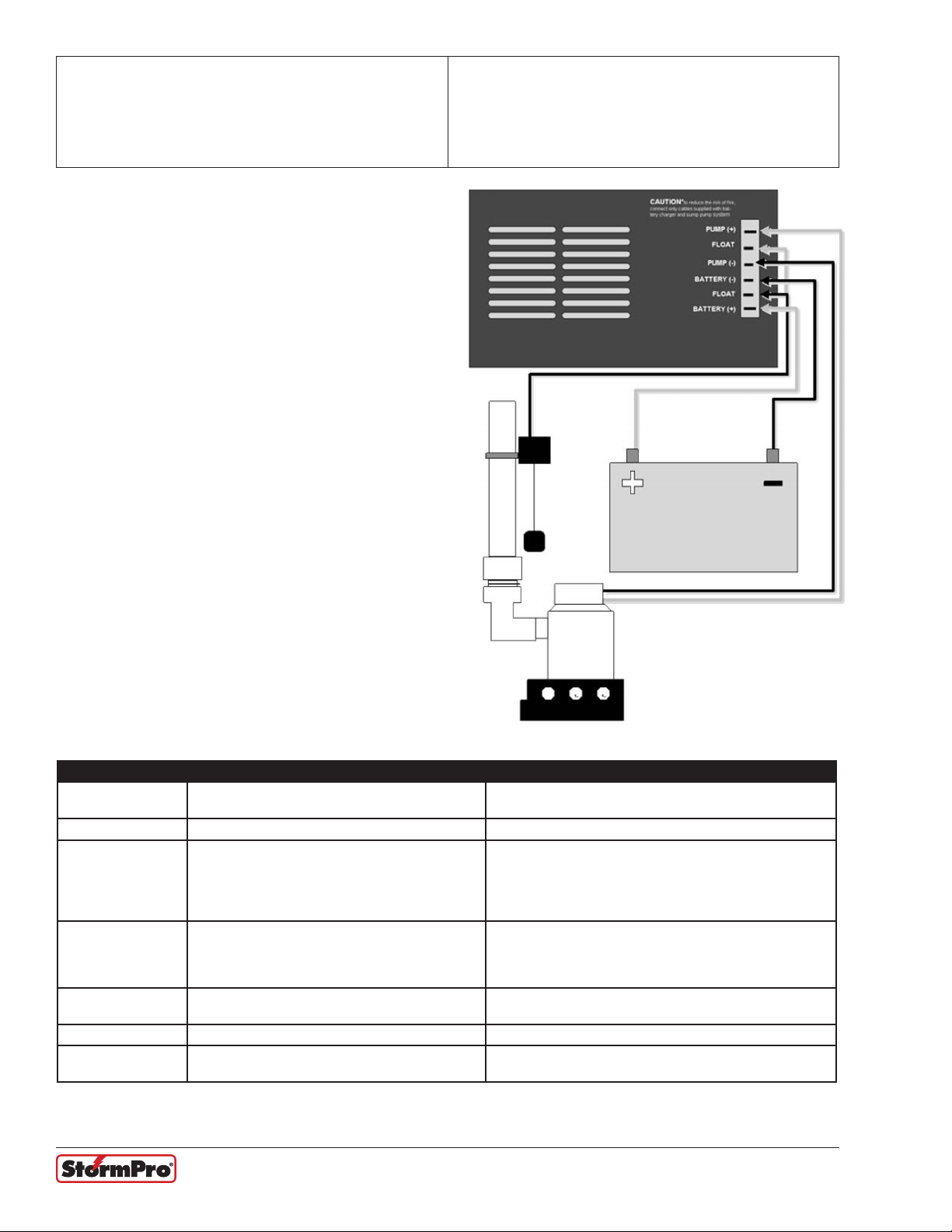
The backup pump, backup oat switch, and battery
will all connect into the back of the charger unit. Make
sure to use correct polarity.
Pump
Start with the backup pump wires, the terminals are
different sizes to ensure correct polarity, do not force
the terminal onto the plug. Connect the backup pumps
negative (-) black wire to the charger units negative
(-) pump post and connect the pumps positive (+)
brown wire to the charger units positive (+) pump
post.
Float
Connect the black and white wires to the charger’s
oat switch terminals. Polarity with the oat switch
wires is not critical. The wires can be connected to
either terminal.
Battery
The battery should be placed inside its protective
battery box before being connected to the charger
unit. Make sure that the charger unit is not plugged
into the wall outlet.
Register your product at www.sumpro.com
Page 4
StormPro® 2100DC
Heavy Duty 12V DC Pump
1. Take the negative (-) black battery wire and
fasten the ring terminal securely to the negative
(-) battery post on top of the battery.
2. Take the Positive(+) red battery wire and fasten
the ring terminal securely to the Positive(+)
battery post on top of the battery.
3. The battery terminals are different sizes to
ensure correct polarity, do not force the
terminal on to the plug if it does not t. Connect
the negative (-) black wire to the charger units
(-) battery post and connect the positive (+) red
wire to the charger units positive (+) battery
post.
4. After all the terminals have been installed
properly plug the charger unit into a dedicated
115V wall outlet.
OPERATION MANUAL
Dated: 03/15/2013
Document Name: StormPro_2100DC_OM
Page 4 of 8
Error Description Possible Causes Fix
The battery failed
pre-qualication test
Battery over-voltage The charger is connected to a 24 volt battery Replace the battery with a 12-volt deep-cycle marine battery
Charge time monitor Battery took too long to complete its charge:
Excessive battery
drain
Reverse battery
connection
Battery overheated Cells in an old battery may deteriorate with age Replace the battery with a 12-volt deep-cycle marine battery
Charging error An internal error occurred in the charger during one
Pump motor ran during charging (that is, with the
main A.C. power ON), causing the system to shut
Charger is connected backwards to the battery.
(That is, charger (+) to battery (-) and vice versa)
The battery is highly sulfated
The charger is connected to a six-volt battery
A. Load applied (e.g. the pump motor
started) during charging
B. The battery ampere-hour rating is too
large (max. 130 ampere-hours)
down
of the charging states
Replace the battery with a 12-volt deep-cycle marine battery
Replace the battery with a 12-volt deep-cycle marine battery
A: Be sure the pump cannot start during
charging; reset the charger
B: Replace with correct size battery
Check primary sump pump. The BBU generally runs only
when the main A.C. power is out. If there has not been any
power outage and the BBU has run, the primary pump itself
may have failed
Reconnect charger (+) to battery (-)/(-) to (-)
Unplug the charger for 10 seconds and then plug it in again.
If error occurs again, refer to table below
Register your product at www.sumpro.com
Page 5
StormPro® 2100DC
Heavy Duty 12V DC Pump
OPERATION MANUAL
Dated: 03/15/2013
Document Name: StormPro_2100DC_OM
Page 5 of 8
error lIght IndIcatIonS
Note: This chart identies light codes indicating
various charger error modes. It only applies when the
‘Charger Mode’ light ashes yellow/green alternately.
The light codes listed here do not relate.
“Silence Alarm/Reset” Rocker Switch:
Push the left side of the rocker switch on the front of
the charger to silence the alarm.
Note: This will not silence the alarm when the battery
Push the right side of the rocker switch to reset the
‘Pump System Status’ LED after the pump has directly
to the legends on the charger housing (A.C. Power
Status, Pump Run Status, Alarm Silence, etc.). The
legends on the charger apply only when the ‘Charger
Mode’ light is not ashing yellow/green. run, or to reset
the system from an error mode. When you reset the
system, the charger will start its diagnostic procedure
(pre-qualication test, etc.) from the beginning. If the
cause of the error mode is not corrected, the system
will go into the error mode again.
is below 8.2 volts or the system is in error mode.
LED Status
A.C. Power Status Pump Run Status Alarm Silence Charge Mode Error Mode
Flashing
Flashing
Flashing
Flashing
Off
Off
Off
Off
Off
Flashing
Flashing
Off
Flashing
Flashing
Off
Flashing
Off
Flashing
Flashing
Off
Flashing
Flashing Yellow/Green
Flashing Yellow/Green
Flashing Yellow/Green
Flashing Yellow/Green
Flashing Yellow/Green
Flashing Yellow/Green
Flashing Yellow/Green
Battery Overheated
Charge Time Monitor
Excessive Battery Drain
Failed Pre-Qualication Test
Battery Over-Voltage
Reverse Battery Connection
Output Over-Current
Charger Light On/Off/Flashing Alarm Buzzer Indicates
All LEDs Flash ONCE Off Connected system to AC power or to battery; or, pressed
AC Power Status On
Very Slow Flash
Pump Run Status Fast Flash (2x/second)
Slow Flash (1x/2 seconds)
Off
Alarm Silence On
Off
Battery Status On
Slow Flash
Fast Flash
Off
Charger Mode Slow YELLOW Flash
Solid YELLOW Flash
Fast YELLOW Flash
Solid GREEN
Flashing alternately YELLOW/
GREEN
Off
Off
Beep in synch
with LED Flash
Off
Off
Off
On
On
Off
Off
Off
Off
Off
On - Beeping
Pump is running. Press LEFT side of rocker switch
System is not connected to a battery or is connected to a
Battery voltage less than 10.9 volts. Alarm can be silenced
Battery voltage is less than 8.2 volts. Alarm CANNOT
System is in “pre-qualication” stage. This will last from 1
minute to 5 hours, depending on the condition of your battery
System is in the “Constant Current Charge” stage. This will
continue until the battery voltage reaches approximately
System is in the “Constant Voltage Charge” stage. This could
System is in ERROR mode. Alarm will beep in synch with one
or more of the ‘AC Power Status’, ‘Pump Run Status’, or ‘Alarm
‘Reset’ when in ERROR mode
System is receiving AC power
System is not receiving AC power
to silence alarm
Pump has run, but is not running now
Pump has not run
Alarm is silenced
Alarm is active
battery charged to less than 1 volt DC
be silenced
System is properly connected to a battery
14.3 volts
last up to 14.5 hours
Battery is fully charged
Silence’ LEDs.
Register your product at www.sumpro.com
Page 6
StormPro® 2100DC
Heavy Duty 12V DC Pump
OPERATION MANUAL
Dated: 03/15/2013
Document Name: StormPro_2100DC_OM
audIo alarM IndIcatIonS
Audio Alarm Mode Indicates Action
On - Beeping Slow beep in synch with ‘Battery
Status’ LED
On - Beeping Fast beep in sync from ‘Battery
Status’ LED
On - Beeping Fast beep in synch with one or
more of the ‘AC Power Status’,
‘Pump Run Status’, or ‘Alarm
Silence’ LEDs and with the
‘Charger Mode’ LED ashing
alternately YELLOW/GREEN
On - Beeping Fast beep in synch with ‘Pump Run
Status’ LED
Battery is down to
about 10.9 volts
Battery is down to
about 8.2 volts
System is in ERROR
mode
Pump is running None. Alarm will stop when pump stops running. To silence
Investigate cause; battery is very low. You have limited
pump run time left. Press and release LEFT side of toggle
switch to silence alarm.
Investigate cause; battery is nearly dead. You have almost
no pump run time left. Alarm CANNOT be silenced
Refer to ERROR Mode Charts
alarm, press and release LEFT side of toggle switch
Page 6 of 8
warranty regIStratIon card
Please ll out and send back to: Metropolitan Ind. Warranty Department P.O. Box 7266 Romeoville, IL 60446. Or
to register online, go to www.sumpro.com
StormPro® 2100DC Warranty Registration Card
To register your purchase, please ll in the following information:
Name:
Address:
City
Purchased From:
State: Zip:
Date:
Installed By:
Register your product at www.sumpro.com
Phone:
Page 7

StormPro® 2100DC
Heavy Duty 12V DC Pump
noteS
OPERATION MANUAL
Dated: 03/15/2013
Document Name: StormPro_2100DC_OM
Page 7 of 8
Register your product at www.sumpro.com
Page 8

StormPro® 2100DC
Heavy Duty 12V DC Pump
1. Coverage and Term. Metropolitan Industries, Inc. (“Metropolitan”) warrants to the original
purchaser (the “Buyer”) of each StormPro/Sumpro product (the “product”), that any part thereof which proves
to be defective in material or workmanship within three (3) years from date of manufacture, will be replaced at
no charge with a new or remanufactured part, F.O.B. factory. Buyer shall be responsible for all freight charges
and all costs of fi eld labor or other charges incurred in the removal and/or reinstallation of any product, part
or component thereof.
2. Exclusions. THE WARRANTY IS SUBJECT TO THE FOLLOWING CONDITIONS AND
EXCLUSIONS:
(a) The Warranty excludes products or workmanship which becomes defective as a result
of: (i) earthquake, fi re, storms, the elements or any other acts of God; (ii) normal wear and tear from use;
(iii) accident, misuse, abuse or neglect; (iv) modifi cations made by Buyer or any third party, other than
Metropolitan; and (v) Buyer’s failure to properly install, maintain, service and/or operate the product under
normal conditions and according to manufacturer’s instructions.
(b) Metropolitan shall not be responsible for, and the Warranty shall not cover, extended
damage which occurs because of Buyer’s failure to notify Metropolitan promptly in writing of apparent
defects.
(c) Any part or component designated as manufactured by anyone other than Metropolitan
shall be covered only by the express warranty of the manufacturer thereof.
(d) The Warranty shall lapse upon Buyer’s failure to fully comply with the terms and conditions
of its contract with Metropolitan, including Buyer’s failure to pay the purchase price for the product or any
portion thereof. Buyer’s subsequent compliance with the terms and conditions of any such contract, will not
cause the term of the Warranty to extend beyond the time period set forth above.
(e) No actions taken by Metropolitan to correct a defect in a product shall extend the Warranty
beyond the period set forth above. Metropolitan shall not be obligated to remedy any defect, where otherwise
required pursuant to the Warranty unless and until Buyer notifi es Metropolitan in writing of the defect and
then only if such notifi cation is made prior to the expiration of the period set forth above.
3. Process of Claims and Repairs. Metropolitan agrees that if the product or any part or component
thereof shall fail to conform to the terms of this Warranty, Metropolitan shall replace such nonconforming
product, part or component at the original point of delivery and furnish instruction for its disposition. Any
transportation charges involved in such disposition and all costs of fi eld labor or other charges incurred in the
removal and/or reinstallation of any product, part or component thereof shall be the responsibility of Buyer.
4. Limitation on Liability. Notwithstanding any provision to the contrary, Metropolitan’s entire
liability under this Warranty shall not in the aggregate exceed, and Buyer’s exclusive and sole remedies
are, to the extent permitted by law, shall be to secure replacement of the defective product. UNDER NO
CIRCUMSTANCES SHALL METROPOLITAN BE LIABLE UNDER THE WARRANTY FOR
ANY INDIRECT, PUNITIVE, SPECIAL, EXEMPLARY, CONSEQUENTIAL OR INCIDENTAL
DAMAGES (INCLUDING LOST PROFITS, REVENUE, USE OR ECONOMIC ADVANTAGE).
5. Express Waiver of Any Other Warranties. THE EXPRESS WARRANTY SET FORTH IN THIS
WRITTEN WARRANTY IS THE ONLY WARRANTY MADE BY METROPOLITAN, OR ANY OTHER
PARTY, IN CONNECTION WITH ANY PRODUCT PURCHASED FROM METROPOLITAN.
NEITHER METROPOLITAN, NOR ANY OTHER PARTY, MAKES ANY OTHER EXPRESS OR
IMPLIED WARRANTY WHICH IS NOT SET FORTH HEREIN, AND METROPOLITAN HEREBY
DISCLAIMS AND BUYER HEREBY WAIVES ALL IMPLIED WARRANTIES, INCLUDING THE
IMPLIED WARRANTY OF MERCHANTABILITY AND THE IMPLIED WARRANTY OF FITNESS
FOR A PARTICULAR PURPOSE.
6. Not Transferable. The Warranty may not be transferred and shall be void on the sale or other transfer
of the product.
7. Products and Warranty Subject to Change. Metropolitan reserves the right to make revisions to its
products and their specifi cations, and to revise this Warranty and related information without notice.
OPERATION MANUAL
Dated: 03/15/2013
Document Name: StormPro_2100DC_OM
Page 8 of 8
3 Year Residential Warranty
Register your product at www.sumpro.com
 Loading...