

Page 1
:
0
-
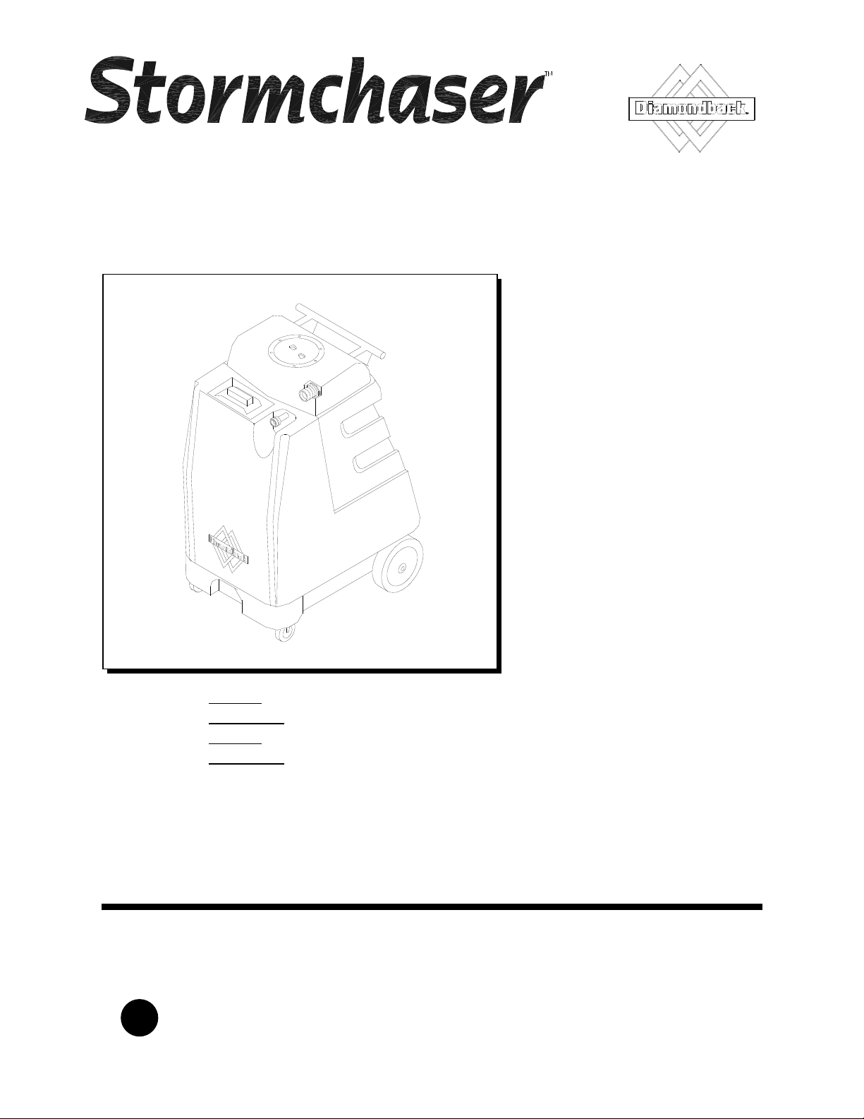
PORTABLE EXTRACTOR
MODELS
10070480
900-04
10070500
90
01
Operating Instructions
Read these instructions before using the machine
V
86038660 05/16/11
PRV NO. 98844
Page 2
MACHINE DATA LOG/OVERVIEW
Model:
Date of Purchase:
Serial Number:
Sales Representative:
Address:
Phone Number
:
OVERVIEW
The Stormchaser is an electric powered carpet extractor intended for commercial use. This appliance
applies a cleaning solution to the carpet and then vacuums the soiled water back into the recovery tank.
Warranty Registration
Thank you for purchasing a C400 product. Warranty registration is quick and easy.
Your registration will allow us to serve you better over the lifetime of the product.
To register your product go to:
www.century400.com/support/warranty/register.php
For customer assistance:
1-800-776-2436
2
STORMCHASER 86038660 05/16/11
Page 3

Machine Data Log/Overview.........................2
Table of Contents..........................................3
HOW TO USE THIS MANUAL
How to use this Manual.................................1-1
SAFETY
Important Safety Instructions........................2-1
Hazard Intensity Level. .................................2-2
Safety Label Location. ..................................2-3
Grounding Instructions..................................2-4
OPERATIONS
Technical Specifications. ..............................3-1
Controls.........................................................3-2
Machine Operation........................................3-3
Pre-Run Machine Inspection......................3-3
Equipment Set-Up......................................3-3
Priming the Pump. .....................................3-3
Emptying & Cleaning Tanks.......................3-4
Shut Down and Storage.............................3-4
MAINTENANCE
Daily Maintenance ........................................4-1
Periodic Maintenance ...................................4-1
Monthly Maintenance....................................4-1
Semi-annually...............................................4-1
Lubrication ....................................................4-1
Storage .........................................................4-1
Solution Pump Replacement ........................4-2
Vacuum Motor Replacement ........................4-2
Pump Replacement Kits ...............................4-3
Pressure Regulator.......................................4-4
Machine Troubleshooting..............................4-5
TABLE OF CONTENTS
GROUP PARTS LIST
Control Panel Group.....................................5-1
Frame Group (100 psi) .................................5-3
Frame Group (200 psi) .................................5-5
Pump Group (100 psi) ..................................5-7
Pump Group (200 psi) ..................................5-9
Recovery Tank Group................................. 5-11
Vacuum Motor Group (Upper).................... 5-13
Vacuum Motor Group (Lower).................... 5-15
Wiring Diagram (100 psi)............................ 5-17
Wiring Diagram (200 psi)............................ 5-18
Suggested Spare Parts............................... 5-19
Notes .......................................................... 5-20
Warranty..................................................... 5-21
STORMCHASER 86038660 03/29/07
3
Page 4
HOW TO USE THIS MANUAL
This manual contains the following sections:
- HOW TO USE THIS MANUAL
- SAFETY
- OPERATIONS
- MAINTENANCE
- PARTS LIST
The HOW TO USE THIS MANUAL section will tell
you how to find important information for ordering
correct repair parts.
Parts may be ordered from authorized dealers.
When placing an order for parts, the machine model
and machine serial number are important. Refer to
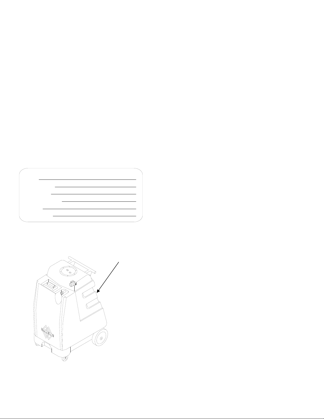
the MACHINE DATA box which is filled out during
the installation of your machine. The MACHINE
DATA box is located on the inside of the front cover
of this manual.
Model:
Date of Purchase:
Serial Number:
Sales Representative:
Address:
Phone Number
The model and serial number of your machine is on
the inside of the control panel.
:
The SAFETY section contains important information
regarding hazard or unsafe practices of the
machine. Levels of hazards is identified that could
result in product or personal injury, or severe injury
resulting in death.
The OPERATIONS section is to familiarize the
operator with the operation and function of the
machine.
The MAINTENANCE section contains preventive
maintenance to keep the machine and its
components in good working condition. They are
listed in this general order:
- Service Schedule
- Lubrication
- Storage
- Vacuum Motor Replacement
- Solution Pump Replacement
- Pump Kits
- Pressure Regulator (200PSI model only)
- Troubleshooting
The PARTS LIST section contains assembled parts
illustrations and corresponding parts list. The parts
lists include a number of columns of information:
- REF – column refers to the reference
number on the parts illustration.
- PART NO. – column lists the part
number for the part.
- PRV NO. – reference number.
- QTY – column lists the quantity of the
part used in that area of the machine.
- DESCRIPTION – column is a brief
description of the part.
- SERIAL NO. FROM – column indicates
the first machine the part number is
applicable to. When the machine design
has changed, this column will indicate
serial number of applicable machine.
The main illustration shows the most
current design of the machine. The
boxed illustrations show older designs. If
column has an asterisk (*), call
manufacturer for serial number.
- NOTES – column for information not
noted by the other columns.
NOTE: If a service or option kit is installed on your
machine, be sure to keep the KIT INSTRUCTIONS
which came with the kit. It contains replacement
parts numbers needed for ordering future parts.
1-1
STORMCHASER 86038660 05/16/11
Page 5
SAFETY INSTRUCTIONS
!
IMPORTANT SAFETY INSTRUCTIONS
When using an electrical appliance, basic precaution
must always be followed, including the following:
READ ALL INSTRUCTIONS BEFORE USING THIS MACHINE.
This machine is for commercial use.
To reduce the risk of fire, electric shock, or injury:
WARNING:
Connect to a properly grounded outlet. See Grounding Instructions.
Do not leave the machine unattended. Unplug machine from outlet when not in use and before
maintenance or service.
Use only indoors. Do not use outdoors or expose to rain.
Do not allow machine to be used as a toy. Close attention is necessary when used by or near
children.
Use only as described in this manual. Use only manufacturer’s recommended components and
attachments.
Do not use damaged electrical cord or plug. Follow all instructions in this manual concerning grounding
the machine. If the machine is not working properly, has been dropped, damaged, left outdoors, or
dropped into water, return it to an authorized service center.
Do not pull or carry machine by electrical cord, use as a handle, close a door on cord, or pull cord
around sharp edges or corners.
Do not run machine over cord. Keep cord away from heated surfaces.
Do not unplug machine by pulling on cord. To unplug, grasp the electrical plug, not the electrical cord.
Do not handle the electrical plug or machine with wet hands.
Do not operate the machine with any openings blocked. Keep openings free of debris that may reduce
airflow.
This machine is intended for cleaning carpet only.
Do not vacuum anything that is burning or smoking, such as cigarettes, matches, or hot ashes.
This machine is not suitable for picking up health endangering dust.
Turn off all controls before unplugging.
Machine can cause a fire when operating near flammable vapors or materials. Do not operate this
machine near flammable fluids, dust or vapors.
This machine is suitable for commercial use, for example in hotels, schools, hospitals,
factories, shops and offices for more than normal housekeeping purposes.
Maintenance and repairs must be done by qualified personnel.
If foam or liquid comes out of machine, switch off immediately.
SAVE THESE INSTRUCTIONS
STORMCHASER 86038660 03/29/07
2-1
Page 6

HAZARD INTENSITY LEVEL
The following symbols are used throughout this guide as indicated in their descriptions:
HAZARD INTENSITY LEVEL
There are three levels of hazard intensity identified by signal words -WARNING and CAUTION and FOR
SAFETY. The level of hazard intensity is determined by the following definitions:
! WARNING
WARNING - Hazards or unsafe practices which COULD result in severe personal injury or death.
! CAUTION
CAUTION - Hazards or unsafe practices which could result in minor personal injury or product or property
damage.
FOR SAFETY: To Identify actions which must be followed for safe operation of equipment.
Report machine damage or faulty operation immediately. Do not use the machine if it is not in proper
operating condition. Following is information that signals some potentially dangerous conditions to the
operator or the equipment. Read this information carefully. Know when these conditions can exist. Locate
all safety devices on the machine. Please take the necessary steps to train the machine operating
personnel.
FOR SAFETY:
DO NOT OPERATE MACHINE:
Unless Trained and Authorized.
Unless Operation Guide is Read and understood.
In Flammable or Explosive areas.
In areas with possible falling objects.
WHEN SERVICING MACHINE:
Avoid moving parts. Do not wear loose clothing; jackets, shirts, or sleeves when working on the
machine.
.
2-2
STORMCHASER 86038660 03/29/07
Page 7
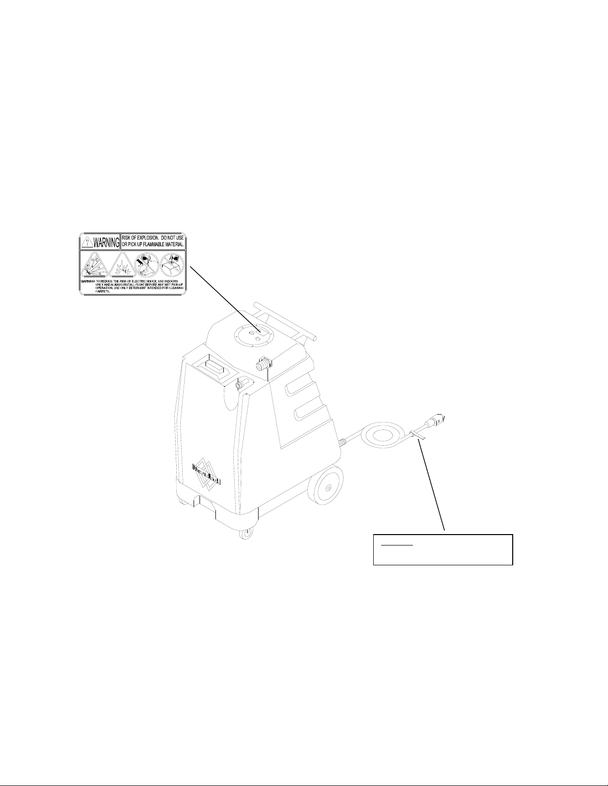
SAFETY LABEL LOCATION
NOTE: These drawings indicate the location of safety labels on the machine. If at any time the labels be come
illegible, promptly replace them.
LABEL WARNING
86242230
PRV NO. 500009
WARNING!
FOR YOUR PROTECTION USE A GROUND
FAULT CIRCUIT INTERRUPTER
LABEL CIRCUIT INTERRUPTER
STORMCHASER 86038660 03/29/07
86200570
PRV NO. 170-41
2-3
Page 8
GROUNDING INSTRUCTIONS
THIS PRODUCT IS FOR COMMERCIAL USE
ONLY.
ELECTRICAL:
In the USA this machine operates on a
standard 15 amp 115V, 60 hz, A.C. power
circuit . The amp, hertz, and voltage are listed
on the data label found on each machine.
Using voltages above or below those indicated
on the data label will cause serious damage to
the motors.
EXTENSION CORDS:
If an extension cord is used, the wire size must
be at least one size larger than the power cord
on the machine, and must be limited to 50 feet
(15.5m) in length.
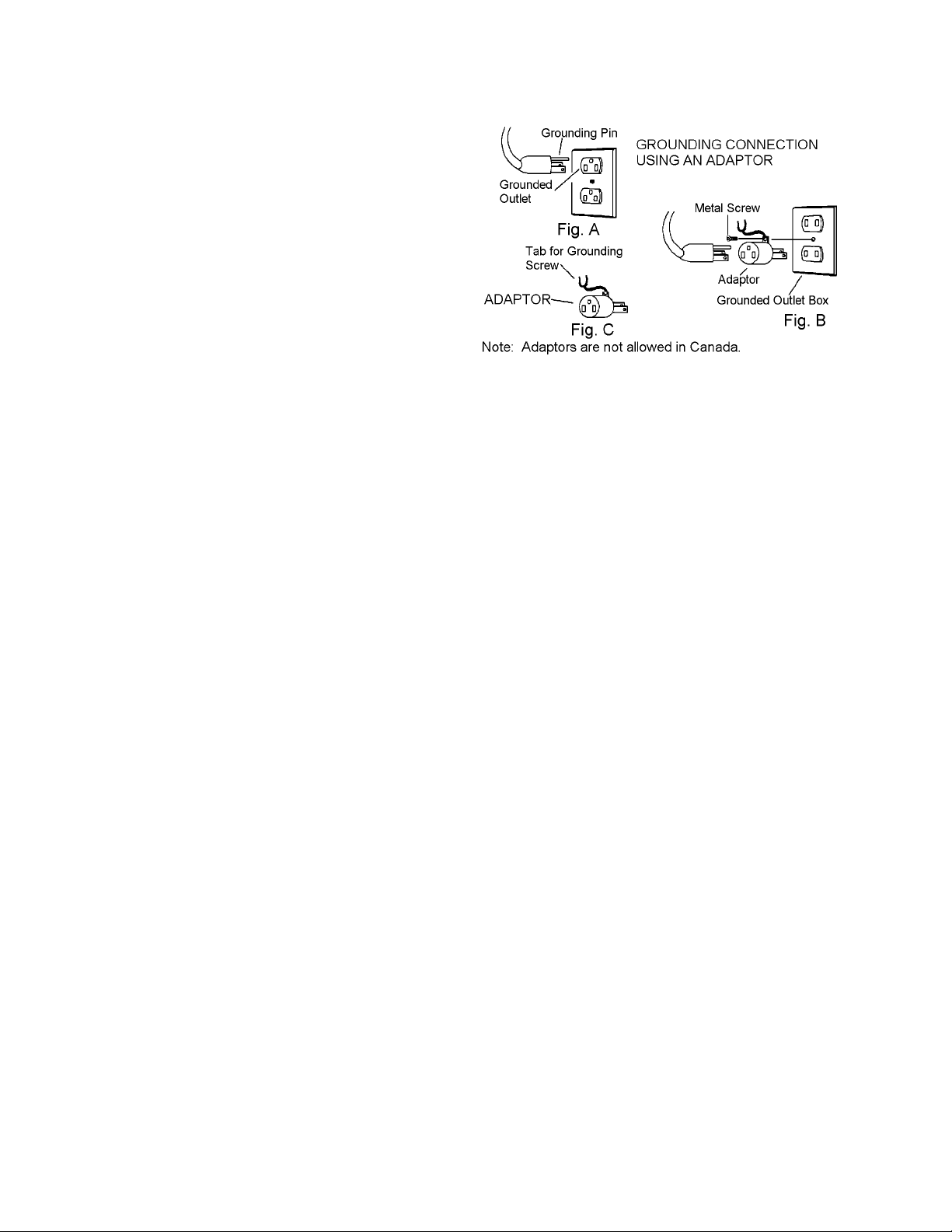
GROUNDING INSTRUCTIONS:
This appliance must be grounded. If it should
malfunction or break down, grounding provides
a path of least resistance for electric current to
reduce the risk of electric shock. This
appliance is equipped with a cord having an
equipment-grounding conductor and grounding
plug. The plug must be inserted into an
appropriate outlet that is properly installed and
grounded in accordance with all local codes
and ordinances.
This appliance is for use on a nominal 120-volt
circuit, and has a grounded plug that looks like
the plug in “Fig. A”. A temporary adaptor that
looks like the adaptor in “Fig . C” may be used
to connect this plug to a 2-pole receptacle as
shown in “Fig. B”, if a properly grounded outlet
is not available. The temporary adaptor should
be used only until a properly grounded outlet
(Fig. A) can be installed by a qualified
electrician. The green colored rigid ear, lug, or
wire extending from the adaptor must be
connected to a permanent ground such as a
properly grounded outlet box cover. Whenever
the adaptor is used, it must be held in place by
a metal screw.
Improper connection of the equipmentgrounding conductor can result in a risk of
electric shock. Check with a qualified
electrician or service person if you are in
doubt as to whether the outlet is properly
grounded. Do not modify the plug provided
with the appliance - if it will not fit the outlet,
have a proper outlet installed by a qualified
electrician.
2-4
STORMCHASER 86038660 03/29/07
Page 9

THIS PAGE LEFT BLANK INTENTIONALLY
STORMCHASER 86038660 03/29/07
2-5
Page 10
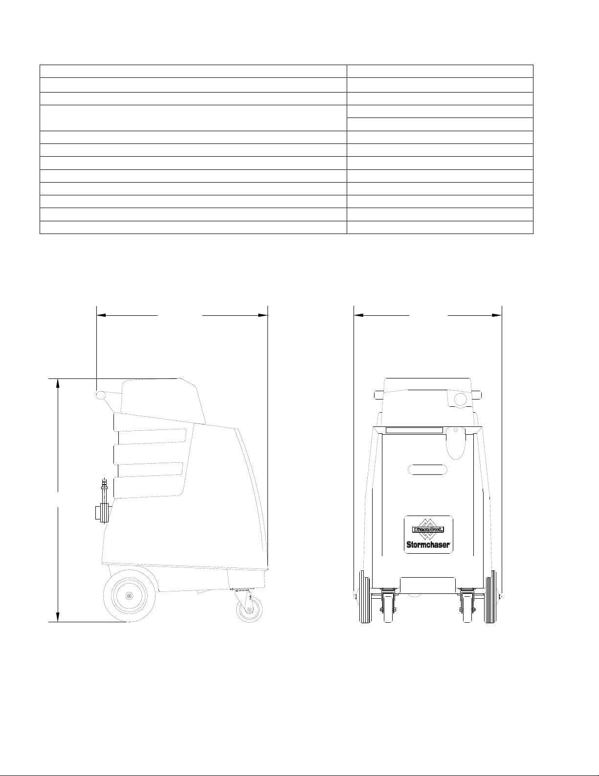
TECHNICAL SPECIFICATIONS
ITEM MEASURE
ELECTRICAL 115 Volt, 60 hz
Vacuum Motor Dual 2 stage
Solution Pump 100 psi
200 psi
Solution Capacity 16 gal (60 L)
Recovery Capacity 14 gal (53 L)
Weight- Empty 95 lbs (43.1 kg)
Weight-Full Solution 230 lbs (104.3 kg)
Height 37 inches (93.98 cm)
Length 27 inches (68.58 cm)
Width 20 inches (50.80 cm)
Power cord 22 feet (6.71 m)
HEIGHT
LENGTH
WIDTH
3-1
STORMCHASER 86038660 10/15/07
Page 11
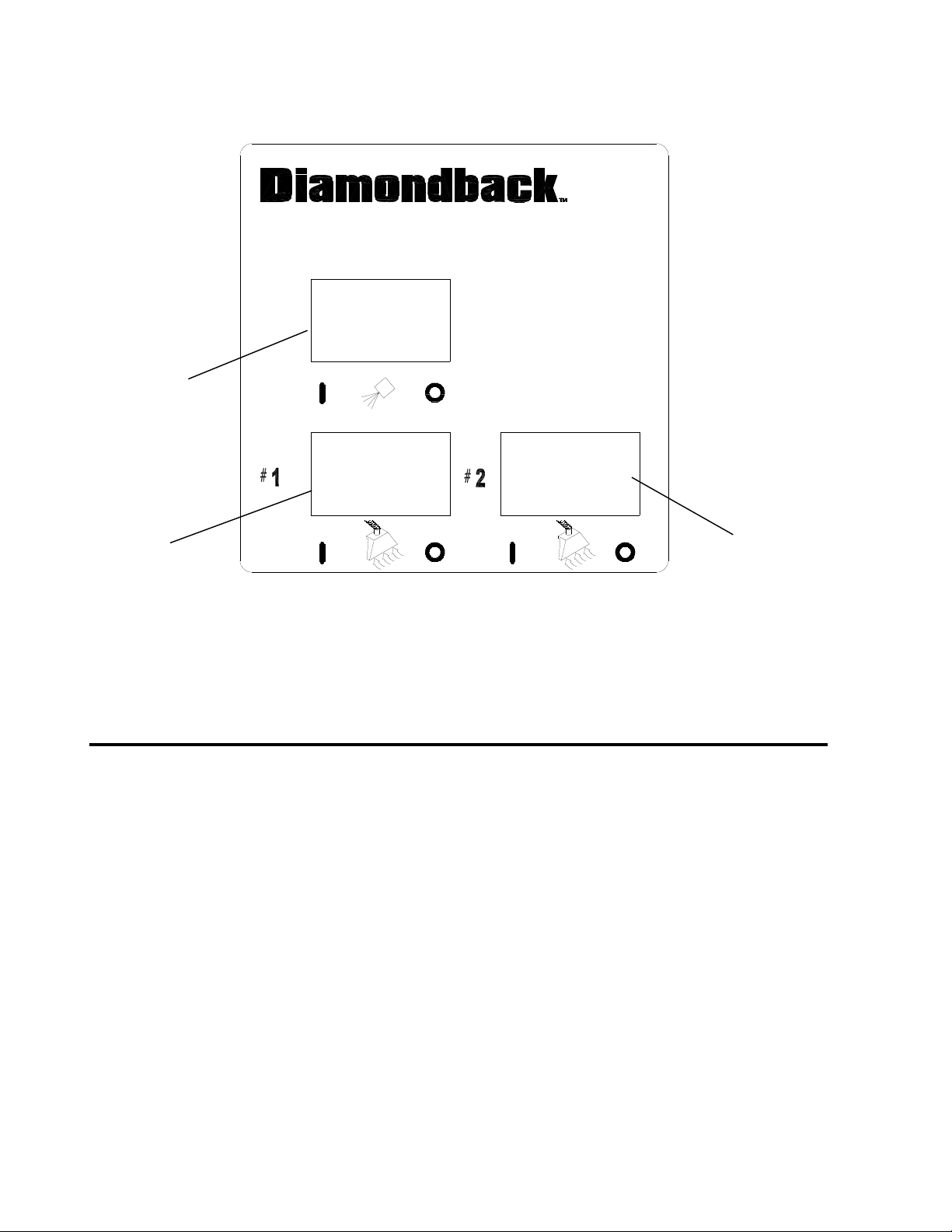
CONTROLS
1
2
3
1. Pump Switch
2. Vacuum #1 Switch
3. Vacuum #2 Switch
STORMCHASER 86038660 03/29/07
3-2
Page 12

MACHINE OPERATION
PRE-RUN INSPECTION
1. Check all fittings and connectors for proper
assembly.
2. Check all hoses for leaks. Repair or replace any
damaged hoses.
3. Check power cord(s) for any damage. If
damaged, replace.
EQUIPMENT SET-UP
1. Plug power cord from machine into properly
grounded wall outlet.
2. Turn vacuum motor switch on and off to make
sure there is electrical power at machine.
3. Connect vac hose to machine. Slide the swivel
cuff over the outlet on the tank.
4. Connect the hose to your machine and wand.
Pull back the knurled collar on the quick
disconnect coupler and push onto the connection
on the chassis. To avoid leaks, check to be that
a positive connection was made.
5. Pour clean, hot water into the solution tank.
To avoid possible tank distortion, water
temperature must not exceed 140 F (60C).
6. Add a non-foaming cleaning solution concentrate,
for use in hot water extractors at the proportions
noted on the container (See list below), into
solution tank. NOTE: When using powder
cleaner, pre-mix with hot water in a clean
container before adding to the solution tank.
7. Turn pump and vacuum switch(s) to the on
position. NOTE: Pump may need to be primed
for solution flow. (see Priming the Pump)
8. Start cleaning.
To prevent possible disease hazard, before
attempting to clean bodily fluids spills, you must
kill any viruses, germs or bacteria present in the
bodily fluid.
SUITABLE INCOMPATIBLE
CHEMICALS CHEMICALS
Alkalis Aldehydes
Clorox II Bleach* Aromatic Hydrocarbons
Defoaming Agents Butyls
Detergents Carbon Tetrachloride
Hydroxides Clorox*
Oxygen Bleaches Chlorinated Bleaches
Soaps Chlorinated Hydrocarbons
Sta-Puf Fabric
Softener* Lysol*
Vinegar Methyls (MEK)
D-Limonene
Perchlorethylene (perc)
Phenols
Trichlorethylene
*Registered Trademark
3-3
STORMCHASER 86038660 03/29/07
PRIMING THE PUMP
1. Connect priming hose to solution output on
machine.
2. Run open end of priming hose to vacuum intake.
3. Turn pump and both vacuums on and seal off
hose going into vacuum in take.
4. Do this for 30 seconds or until pump is putting out
a steady flow of water.
Page 13
EMPTYING AND CLEANING
Always use defoamer
if foaming occurs.
Foam will suspend large particles that may
damage vacuum(s) as well as allow liquid
into the vacuum motor(s) without activating
the float shutoff.
1. Before proceeding, make certain that the
nozzle is functioning properly.
a. To check, hold the wand about one foot
above the surface to be cleaned and
open the wand valve. A full spray should
be observed from the nozzle.
b. If the nozzle is not showing a full spray
pattern, adjust nozzle for proper pattern,
clean, or replace nozzle.
2. Normally, chemical is applied on the push
stroke while vacuuming is done on the pull
stroke. For heavily soiled carpets the hand
tool may be used in the scrubbing manner,
applying chemical in both the push and pull
stroke. A
VACUUM PULL STROKE
LWAYS FINISH UP AN AREA WITH A
.
3. When cleaning, keep the working opening
(wand mouth) flat on the surface being
cleaned. Keep the wand moving when the
valve is open.
4. The shutoff float inside the recovery tank will
impede the vacuum flow when the tank is
full. When this occurs, empty the recovery
tank. Do this by opening the dump valve
located at the back of the machine. NOTE:
Dispose of waste in a proper manner which
would not violate any Local, State or Federal
law.
5. Once the recovery tank has been emptied,
you may once again proceed with cleaning.
CAUTION
!
Operating Vacuum after shutoff has activated could
draw water directly into the vac motor. This will cause
damage to the motor, therefore voiding your
warranty.
CAUTION
!
LWAYS TEST CARPET FOR COLOR FASTNESS IN AN
A
INCONSPICUOUS PLACE
drying times, do not spray too much solution in any
one area.
. Also, to avoid prolonged
STORMCHASER 86038660 03/29/07
MACHINE OPERATION
SHUT DOWN AND STORAGE
1. Turn Switch OFF. Empty recovery tank
completely and rinse several times to
remove any dirt or debris that may be left
behind.
2. Drain any unused cleaning solution from
solution tank and rinse with clean water to
remove any suds left behind by the cleaning
chemicals. NOTE: Dispose of waste in a
proper manner which would not violate any
Local, State or Federal law
3. Run a small amount of clean water through
pump if chemicals were used. This will help
insure the life of your pump.
4. Check the spray jet on the cleaning tool for
full spray pattern and inspect vac head for
any obstructions.
5. Remove as much moisture from system
before storing in cold climates. Excess water
may freeze during storage and crack internal
components, causing damage to the unit.
WARNING
!
Before making any adjustments or performing
any maintenance to your machine, disconnect the
power cord from the electrical source.
3-4
Page 14

MAINTENANCE
DAILY MAINTENANCE
Unplug power cord(s)
before servicing or
making any repairs.
1. Flush the entire system, including floor tool,
hand tool, etc., with 1 to 3 gallons of clean, hot
water.
2. Vacuum out the solution tank.
3. Rinse tank with fresh water. Periodically inspect
the recovery tank and decontaminate if
necessary, using a Hospital Grade Virucide or a
1-10 bleach to water solution. Wastewater
should be disposed of properly.
4. Occasionally check filter screen at the bottom of
the solution tank and rinse clean with hot water if
necessary.
5. Inspect hoses for wear. Frayed or cracked
hoses should be replaced to avoid vacuum or
solution pressure loss.
6. Inspect power cord for wear or damage. This
cable will lie on wet carpet. To prevent electrical
shock replace cords that are frayed or have
cracked insulation immediately.
7. Clean all dirt and obstructions from drain valve
and gaskets to prevent possible leakage and
premature wear.
8. Run clean water through solution pump when
work is complete.
9. Empty both tanks and rinse, run vacuum (s) for
at least one minute to dry motor(s).
10. Store with access covers removed to allow tanks
to dry.
PERIODIC MAINTENANCE
1. Twice a month, flush a white vinegar solution
(one quart vinegar to two gallons water) or antibrowning solution (mixed as directed) through
the extractor. This will prevent build-up of
alkaline residue in the system.
2. If spray jet becomes clogged, remove the spray
tip, wash it thoroughly, and blow dry. NOTE: D
NOT USE PINS
THIS COULD DESTROY THE SPRAY PATTERN
3. Apply silicone lubricant to solution nipple.
4. Periodically inspect all hoses, electrical cable
and connections on your machine. Frayed or
cracked hoses should be repaired or replaced to
eliminate vacuum or solution pressure loss. If
the cable insulation on the power cord is broken
or frayed, repair or replace immediately. Don’t
take chances with electrical fire or shock.
5. Clean outside of all tanks and check for
damage.
, WIRE, ETC. TO CLEAN NOZZLE AS
.
4-1
STORMCHASER 86038660 03/29/07
O
MONTHLY MAINTENANCE
1. Check all bearings for noise and wear.
2. Check all gaskets for wear and leakage.
3. Check pump pressure; observe spray pattern
and check gauge if necessary.
4. Check overall performance of machine.
SEMI-ANNUALLY
Check vacuum motor brushes.
1.
LUBRICATION
For hose fitting lubrication, use a light silicone
lubricant which will not damage o-rings.
STORAGE
Thoroughly clean machine if it is to be stored.
Protect this machine from freezing while in storage.
Page 15
Only qualified maintenance personnel are to
perform the following repairs.
SOLUTION PUMP REPLACEMENT
1. Turn off all switches and unplug the machine.
2. Remove knobs holding recovery tank to solution
tank.
3. Remove recovery tank to gain access to the
pump in base of solution tank.
4. Remove solution hoses from fittings on pump.
Disconnect wires.
5. Remove the screws that fasten the pump to the
solution tank.
6. Reverse process to install new replacement
pump.
VACUUM MOTOR REPLACEMENT
1. Turn off all switches and unplug machine.
2. Remove knobs holding recovery tank to solution
tank.
3. Tip recovery tank to expose one vacuum while
other is located in base of solution tank.
4. Locate the proper vacuum motor wires and
disconnect.
5. Unfasten screws holding vacuum to plate.
6. Remove the vacuum motor.
7. Reverse process to install vacuum motor
replacement.
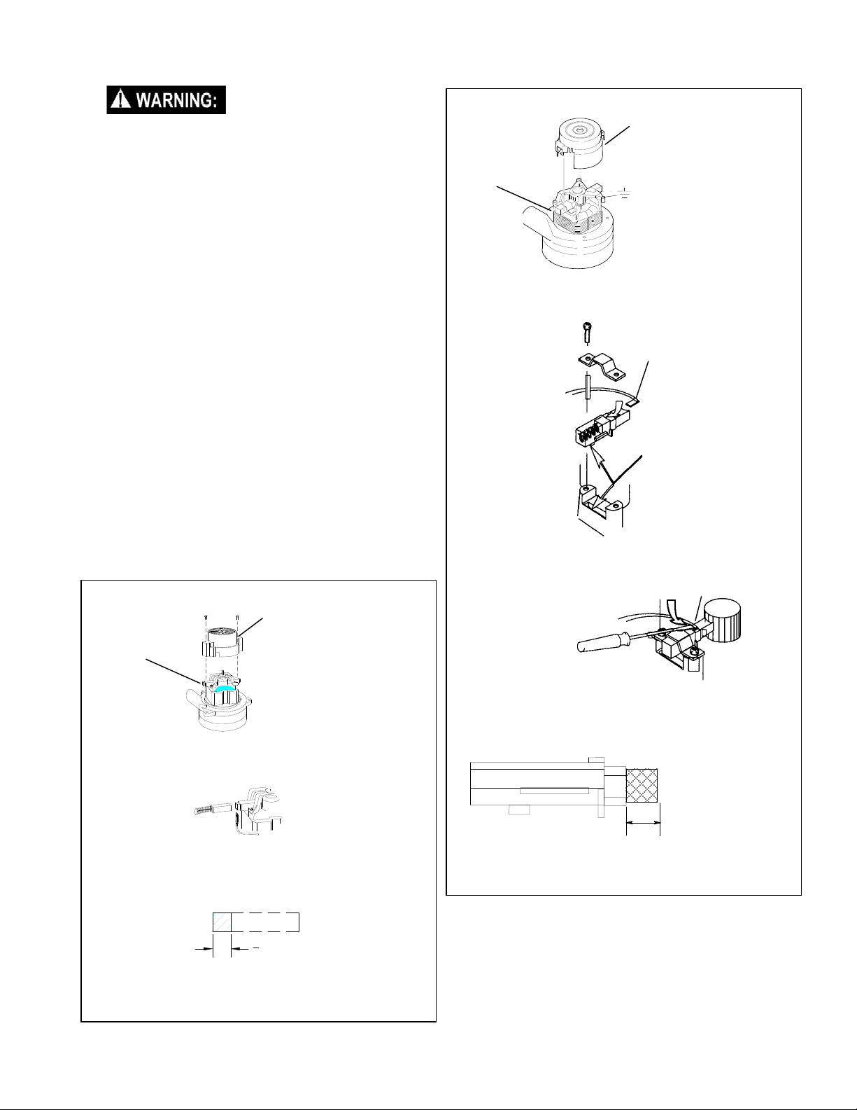
Vacuum Motor Carbon Brushes Replacement (Windsor)
Carbon
Brushes
If armature commutator is grooved, extremely pitted or not
concentric, the motor will need to be replaced or sent to a
qualified service center.
End Cap
WARNING: The green
ground wire must be
attached for safe operation.
See wiring diagram.
MAINTENANCE
Vacuum Motor Carbon Brushes Replacement (Ametek)
End Cap
Carbon
Brushes
Note: When replacing carbon brushes loosen wire terminal
BEFORE removing screws on bracket.
If armature commutator is grooved, extremely pitted or not
concentric, the motor will need to be replaced or sent to a
qualified service center.
Important:
These brushes wear quicker as the length shortens due to
increased heat. Spring inside brush housing will damage
motor if brushes are allowed to wear away completely.
WARNING: The green
ground wire must be
attached for safe operation.
See wiring diagram.
Wire
Terminal
Note:
Place
stop in
groove.
Wire Terminal
Important:
These brushes wear quicker as the length shortens due to
increased heat. Spring inside brush housing will damage
motor if brushes are allowed to wear away completely.
3
[9.5mm]
8
Periodically check the length of the carbon brushes. Replace
both carbon brushes when either is less than 3/8" (9.5mm)
long.
STORMCHASER 86038660 03/29/07
3/8 (9.5mm)
Periodically check the length of the carbon brushes. Replace
both carbon brushes when either is less than 3/8" (9.5mm)
long.
4-2
Page 16
MAINTENANCE
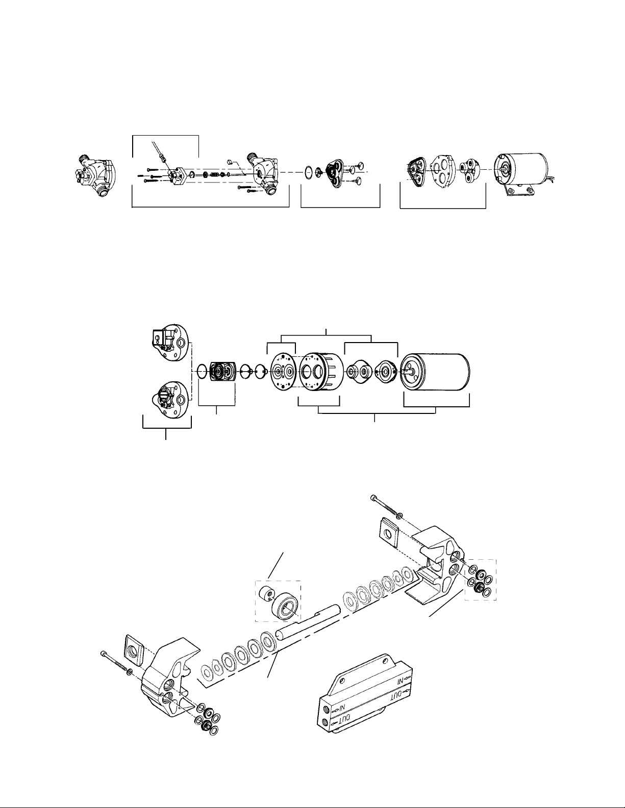
PUMP REPLACEMENT PARTS FOR SHURFLO 100 PSI 86201430 – PRV NO. (250-64A)
PUMP REPLACEMENT PARTS FOR FLOJET 100 PSI 86251110 – PRV NO. (65219)
86161980
PRV NO. 250-67
Switch Asm
Pump Head Replacement
86251040
PRV NO. 65187
86258860
PRV NO. 84166
86251090
PRV NO. 65204
Valve Asm
Bypass Valve Asm
86258830
PRV NO. 84161
Diaphragm
86235120
PRV NO. 29219
86247360
PRV NO. 53245
Motor
Diaphragm
86235100
PRV NO. 29206
4-3
CAM & BEARING KIT
86201170
PRV NO. 250-79G
PLUNGER & SEALS KIT
86201150
PRV NO. 250-79E
STORMCHASER 86038660 03/29/07
VALVE & O-RINGS KIT
86201160
PRV NO. 250-79F
Page 17
E
PRESSURE REGULATOR
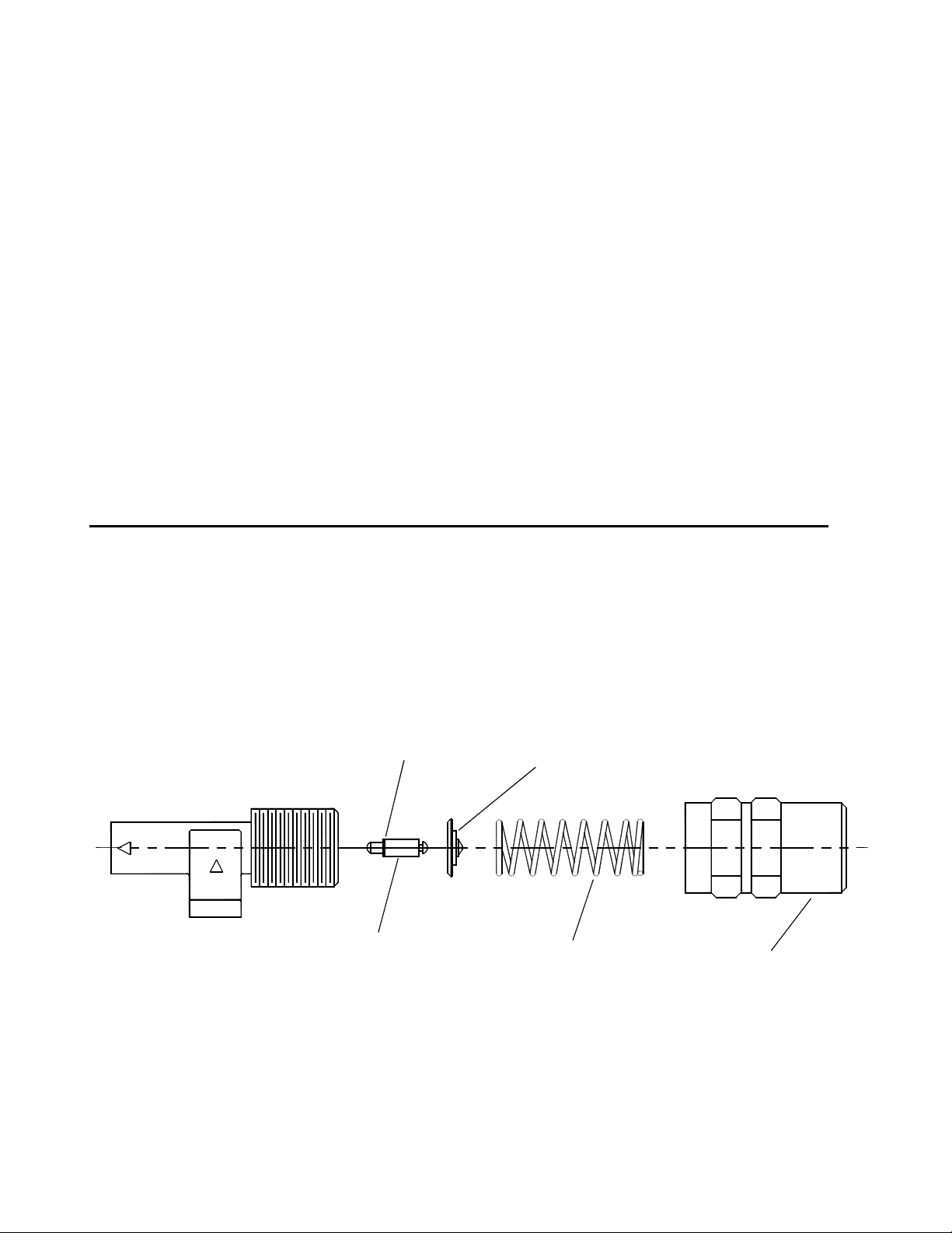
For best results with the pressure regulator, we recommend that you clean and lubricate
the piston and u-cup with Superlube lubricant monthly or when pressure drop seems excessive.
1. Turn unit off before lubricating.
2. Remove cap, spring and spring retainer plate.
3. With fingertips remove piston and u-cup.
4. Wipe piston and u-cup clean of any film or scale.
5. Lubricate the piston and u-cup with Superlube.
6. Reassemble regulator.
7. With pump ON, re-adjust pressure regulator for normal operation.
LUBRICATE U-CUP WITH SUPERLUBE MONTHLY.
MAINTENANC
OUT
I
N
U-CUP
PISTON
SPRING RETAINER PLATE
SPRING
(BLUE- 200 PSI)
STORMCHASER 86038660 03/29/07
CAP
4-4
Page 18
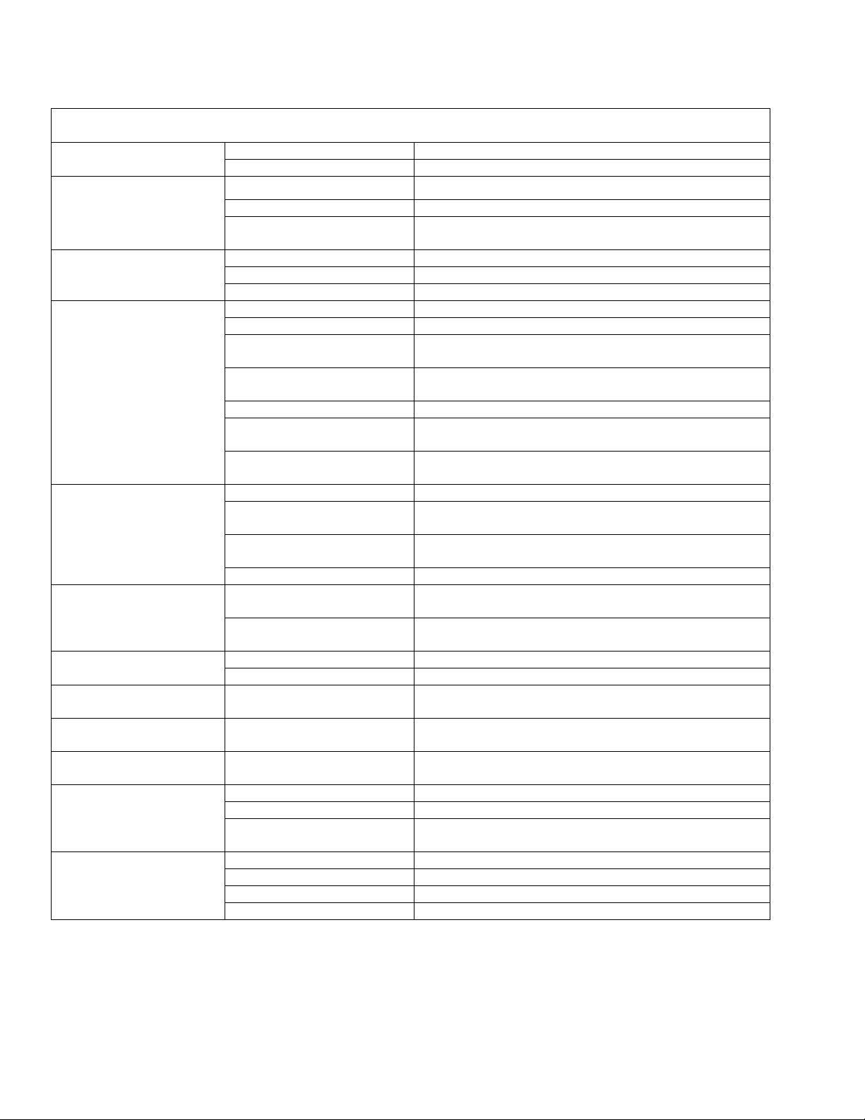
TROUBLESHOOTING
PROBLEM CAUSE SOLUTION
Loss of Power
Electrical shock
Vac motor speed varies
or doesn’t run
Loss of vacuum
Pump runs no solution
Pump not primed Prime pump with provided hose (pg. 3-3)
Pump runs, loss of
pressure
Pump will not run
Solution hose fitting hard
to connect
Carpet not getting clean Severe soil conditions
Carpet too wet Over saturation
Carpet browning
Solution not flowing
properly
Dead electrical circuit Check building circuit breaker or fuse box.
Faulty power cord Replace
Equipment not grounding Follow grounding instructions exactly
Receptacle not grounded Contact an electrician to check building’s wiring
Internal wiring problem
Worn motor brushes Replace
Motor worn out Replace
Faulty switch Replace
Loose vacuum dome Center and seal dome over tank
Crack in dome of poor joint Replace or repair using acrylic plastic cement only
Lint or dirt clogging vacuum
screen
Loose cuffs on vacuum
hose
Vac motor seals leaking Replace
Floor tool vac chamber
clogged
Vac motor, hose, or dome
gasket
Pump inlet screen plugged Clean inlet screen
Pump air locked
Internal or external solution
line damaged and leaking
Internal pump components
wearing out
Check valves in pump head
for particles or cuts in seals
Unit not plugged in Connect unit to 3 prong grounded outlet
Loose wiring See dealer
Corrosion on fittings.
Leaving carpet too wet Check for loss of vac pressure
Too much chemical Check label for correct solution concentration
Light carpet with no brown
prevention
Solution hose connection Check for positive connection
Faulty pump Repair or replace
Faulty floor tool valve Repair or replace
Faulty pump switch Repair
Have a trained service technician check machine’s
wiring
With power off clean screen
Tighten cuffs turning counterclockwise
Wash out with hose. Pick lint out with a wire
Replace
Press trigger to open valve on cleaning wand to
relieve air
Replace
Replace, see pump kit components (pg 4-3)
Take piston from BPR and lubricate with Superlube. If
problem still exists change BPR kit
Clean with steel wool. Soak in acetic acid (white
vinegar). Lubricate lightly with silicone base lubricant.
Make several passes at right angles to each other.
Use a pre-spray.
Adjust solution pressure to lower settings. Make
several passes without spray
Go over carpet with browning prevent only
4-5
STORMCHASER 86038860 03/29/07
Page 19

THIS PAGE LEFT BLANK INTENTIONALLY
STORMCHASER 86038660 03/29/07
4-6
Page 20
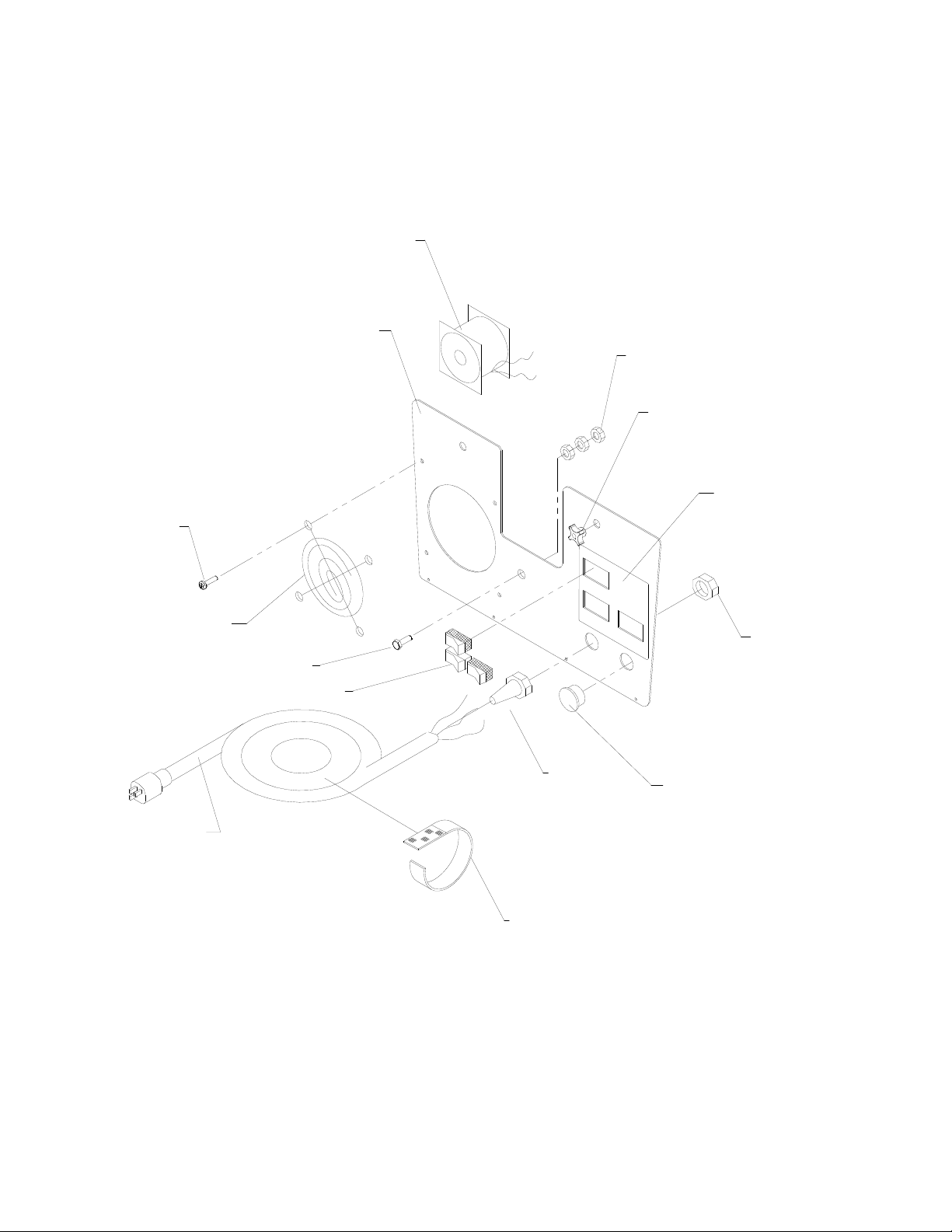
CONTROL PANEL GROUP
1
2
14
13
12
3
4
5
6
9
7
8
10
11
5-1
STORMCHASER 86038660 03/29/07
Page 21
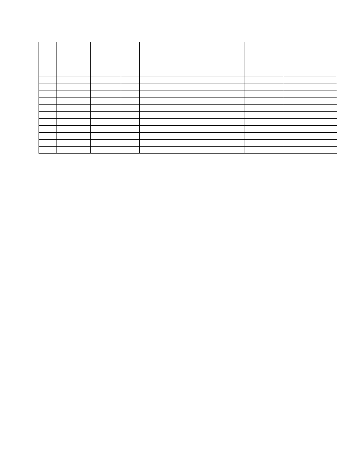
CONTROL PANEL GROUP
REF PART NO. PRV NO. QTY DESCRIPTION
1 86199650 070-08 1 FAN, 105 CRM AXIAL
2 86090900 62899 1 PANEL ASM., CONT. 2 SW W/HEAT
3 86276290 70626 4 SCR, #10 X 3/4 PPHST HI-LO BLK
4 86199660 070-08A 1 FAN FINGER GUARD
5 86273810 70018 1 SCR, 1/4-20 X 1 HHCS SS
6 86256960 72142 3 SWITCH, SPST 15A EURO ROCKER
7 86199540 060-04A 1 CORD 25’ BLK 14/3 SJTW/A PLUG
8 86202160 320-05 1 VELCRO STRAP
9 86256180 73195 1 STRAIN RELIEF, 1/2 NPT (.48ID)
10 86199310 110-14 1 CAP PLUG 7/8”
11 86005670 57040 1 NUT, 1/2 NPT CONDUIT
12 86200610 500346 1 LABEL D/B 3 SWITCH W/HEAT
13 86200500 140-11 2 KNOB RT/TANK
14 86005710 57105 3 NUT, 1/4-20 HEX W/STAR WASHER
SERIAL NO.
FROM
NOTES:
STORMCHASER 86038660 03/29/07
5-2
Page 22
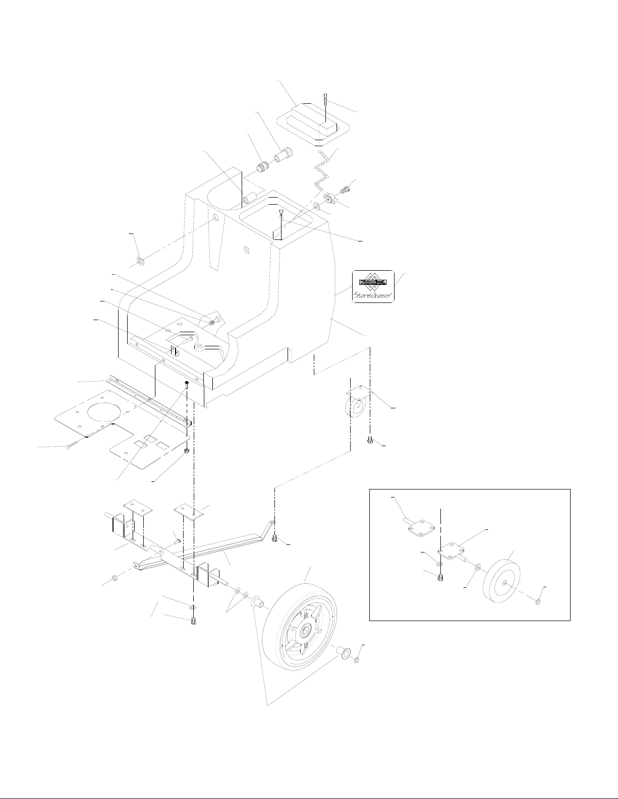
FRAME GROUP (100 PSI)
2
11
23
1
25
24
26
1
22
21
3
4
5
6
7
12
8
9
20
17
10
16
15
16
34
19
18
17
8
13
29
32
14
15
33
30
16
33
28
31
28
34
5-3
35
STORMCHASER 86038660 03/16/09
Page 23
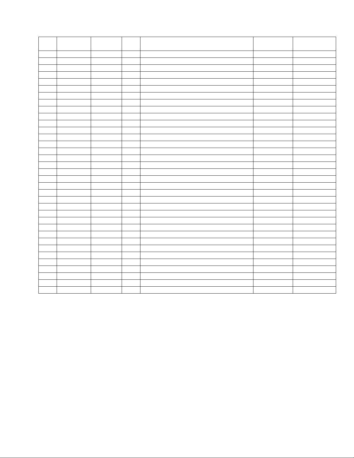
FRAME GROUP (100 PSI)
REF PART NO. PRV NO. QTY DESCRIPTION
1 86201290 280-02 2 RIVET AL. 3/16 X 1/2 CLOSED
2 86201500 260-71 1 SOLUTION COVER D/B
3 86002450 22015 1 COUPLER, 1/4 OD
4 86005590 56014 1 NIPPLE, 1/4 CLOSE
5 86197350 22014 1 COUPLER, 1/4F HEX
6 86091260 87217 1 WASHER, 9/16 ID BENT
7 86201590 290-08 1 SOL. SCREEN (ACORN) W/RUB BASE
8 86210210 70162 4 SCR, 10-32 X 3/8 PPHMS SS
9 86198460 20008 1 CLAMP, 5/8 NYLON UL/CSA
10 86090710 010-02 1 AXLE ASM, RIGHT
11 86200020 41393 1 HINGE, ACCES PANEL
12 86240430 40083 1 HOSEBARB, 3/8MT X 3/8 NYLON
13 86006620 70127 4 SCR, 6-32 X 1/4 PPHMS SS
14 86271350 57187 4 NUT, 6-32 ACORN, ZINC
15 86010630 87013 4 WASHER, 1/4 X 5/8 OD SS
16 86273830 70020 8 SCR, 1/4-20 X 1/2 HHCS SS
17 86271380 57196 2 NUT, 1/2 PUSH-ON DOME CAP
18 86202250 040-06 2 WHEEL 8” BLK CENTERED HUB
19 86090700 010-01 1 AXLE ASM, LEFT
20 86199430 040-03 2 CASTER SWIVEL 4”
21 86033430 75335 1 TANK, SOLUTION DB BLK 100 PSI
22 86200630 500350 1 LABEL, STORMCHASER MAIN
23 86202240 390-24 2 WASHER, 1/4 X 5/8 BONDED NEOPRN
24 86276270 70619 1 SCR, 1/4-20 X 2.0 HHMS SS F/T
25 86232790 27912 1 CHAIN ASM, #10 BEAD S/S W/EYES
26 86242130 48100 1 KNOB, HEX PRESS LOC WING
27 86270900 57037 1 NUT, 1/4-20 WING SS NOT SHOWN
28 86323840 - 2 WHEEL, 12”
29 86091430 05253 1 AXLE ASSEMBLY D.B. 1000137325
30 86079100 620065 2 PLATE AXLE 1000137325
31 86070910 140758 1 BRKT 12” WHEEL MNT BRACE 1000137325
32 86005710 57105 1 NUT, 1/4 -20 HEX W/STAR WASHER
33 86020310 70015 5 SCR, 1/4-20 X 3/4 HHCS SS NP
34 86010710 87080 4 WASHER, .5 X 1.25 FLAT GR8 PLT
35 86323860 - 4 BUSHING FLANGE .501D X .630D
SERIAL NO.
FROM
NOTES:
STORMCHASER 86038660 03/16/09
5-4
Page 24
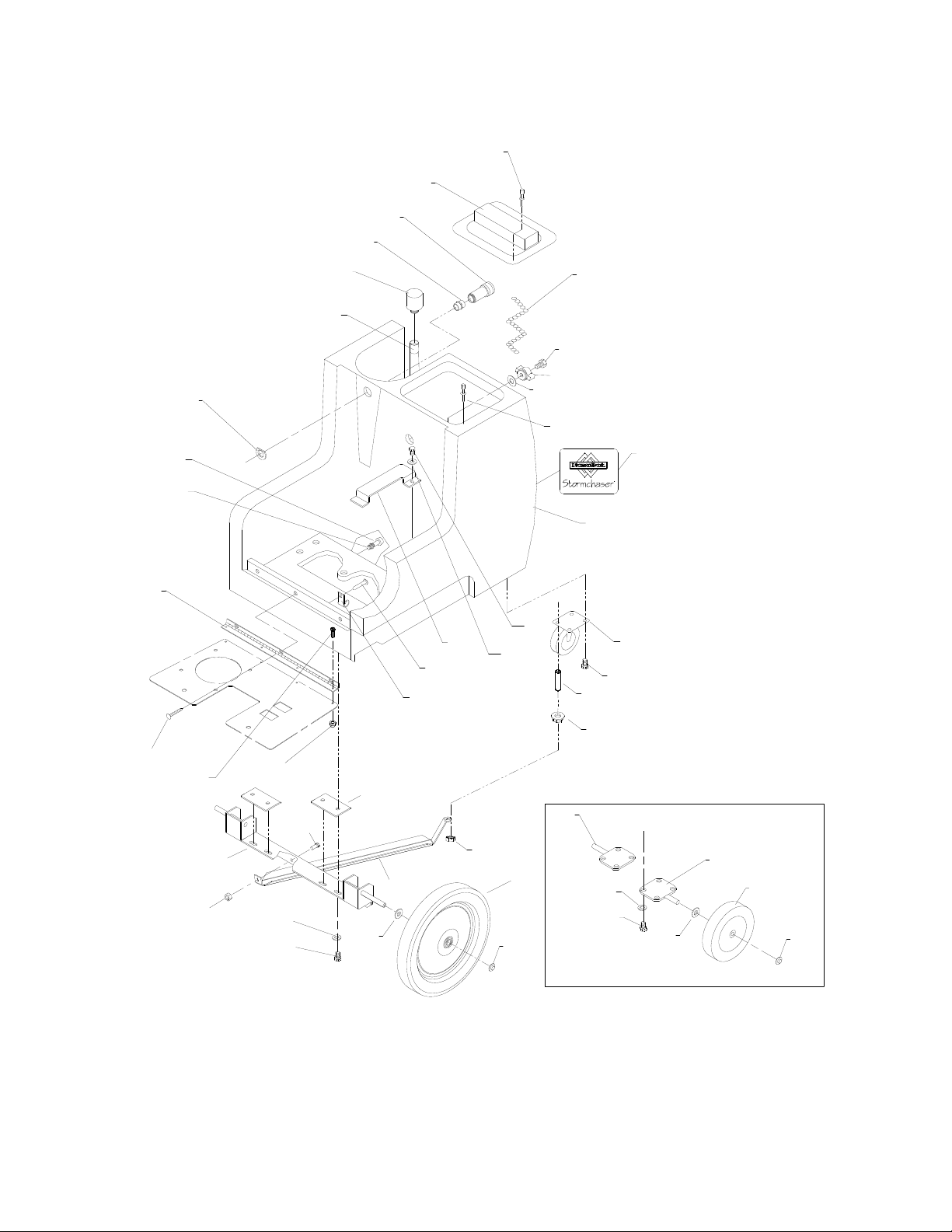
FRAME GROUP (200 PSI)
1
2
3
4
10
11
5
6
7
8
15
21
12
20
16
27
26
28
25
1
24
23
22
16
36
5-5
12
13
34
31
14
32
16
34
33
15
35
38
STORMCHASER 86038660 03/29/07
17
30
37
9
17
15
16
38
18
19
Page 25
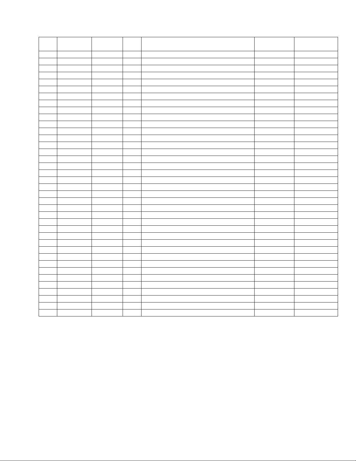
FRAME GROUP (200 PSI)
REF PART NO. PRV NO. QTY DESCRIPTION
1 86201290 280-02 2 RIVET AL. 3/16 X 1/2 CLOSED
2 86201500 260-71 1 SOLUTION COVER D/B
3 86002450 22015 1 COUPLER, 1/4 OD
4 86005590 56014 1 NIPPLE, 1/4 CLOSE
5 86199580 250-35 1 D/B BPR 200PSI
6 86200250 151-50B 1 HOSE, 42” GRY3/8 1/4MP TXCUT
7 86091260 87217 1 WASHER, 9/16OD BENT
8 86201590 290-08 1 SOL SCREEN (ACORN) W/RUB BASE
9 86090710 010-02 1 AXLE ASM, RIGHT
10 86200020 41393 1 HINGE, ACCESS PANEL
11 86240430 40083 1 HOSEBARB, 3/8MT X 3/8 NYLON
12 86274290 70162 4 SCR, 10-32 X 3/8 PPHMS SS
13 86006620 70127 3 SCR, 6-32 X 1/4 PPHMS SS
14 86271350 57187 4 NUT, 6-32 ACORN ZINC
15 86010630 87013 8 WASHER, 1/4ID X 5/8OD SS
16 86020360 70020 17 SCR, 1/4-20 X 1/2 HHCS SS
17 86090700 010-01 1 AXLE ASM, LEFT
18 86202250 040-06 2 WHEEL 8” BLK CENTERED HUB
19 86202250 57196 2 NUT, 1/2 PUSH-ON DOME CAP
20 86198460 20008 1 CLAMP, 5/8 NYLON UL/CSA
21 86099840 065-28 1 DIAMONDBACK 200 PUMP SUPPORT
22 86199430 040-03 2 CASTER SWIVEL 4” SWIVEL
23 86033440 75336 1 TANK, SOLUTION DB BLK 200 PSI
24 86200630 500350 1 LABEL, STORMCHASER MAIN
25 86202240 390-24 2 WASHER 1/4 X 5/8 BONDED NEOPRN
26 86276270 70619 1 SCR, 1/4-20 X 2.0 HHMS SS F/T
27 86232790 27912 1 CHAIN ASM, #10 BEAD SS W/EYES
28 86242130 48100 1 KNOB, HEX PRESS LOC WING
29 86270900 57037 1 NUT, 1/4-20 WING SS NOT SHOWN
30 86202280 89252 2 WHEEL, 12” BLK CNTRD HUB 1000137325
31 86091430 05253 1 AXLE ASSEMBLY D.B. 1000137325
32 86079100 620065 2 PLATE AXLE 1000137325
33 86070910 140758 1 BRKT 12” WHEEL MNT BRACE 1000137325
34 86005710 57105 2 NUT, 1/4 -20 HEX W/STAR WASHER
35 86273780 70015 4 SCR, 1/4-20 X 3/4 HHCS SS NP
36 86006850 70393 1 SET SCR, 1/4-20 X 1.25
37 86271370 57189 1 NUT, 1/4-20 FLANGE LOCK
38 86010710 87080 2 WASHER, .5 X 1.25 FLAT GR8 PLT
SERIAL NO.
FROM
NOTES:
STORMCHASER 86038660 03/29/07
5-6
Page 26
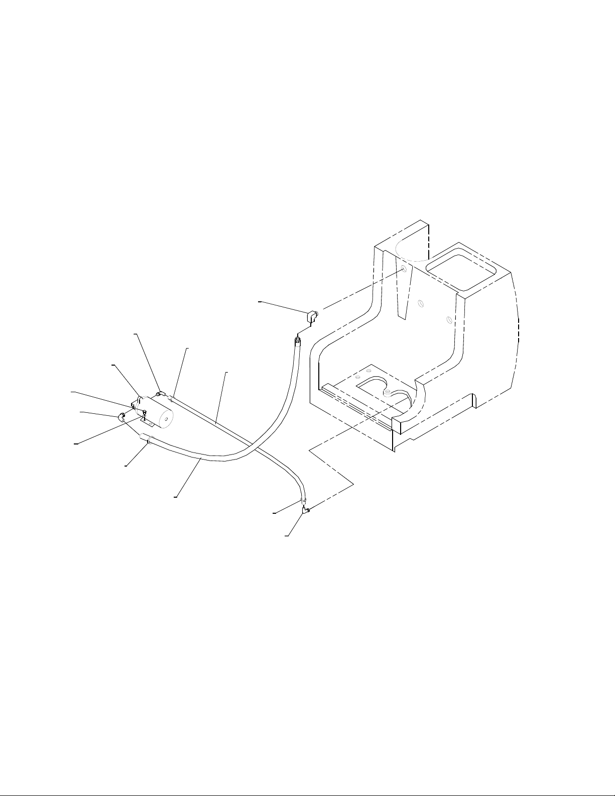
PUMP GROUP (100 PSI)
2
6
9A
9B
1
8
4
2
5
6
7
6
2
5-7
STORMCHASER 86038660 03/29/07
Page 27
PUMP GROUP (100 PSI)
REF PART NO. PRV NO. QTY DESCRIPTION
1 86199640 030-16 1 ELBOW, 1/4 NPT STREET LONG 90D
2 86001550 40043 3 HOSEBARB, 3/8MPT X 3/8 P0D
3 - OPEN - -
4 86020340 70018 2 SCR, 1/4-20 X 1 HHCS SS
5 86010630 87013 2 WASHER, 1/4 ID X 5/8 OD SS
6 86233150 20042 3 CLAMP, 3/8 HOSE (D-SLOT)
7 86200230 151-48B 1 HOSE, 52.5 GRY 3/8 1/4MPTXCUT
8 86280830 39036 1 HOSE, 3/8 NYLOBRAID X 12”
9A 86201430 250-64A 1 SHURFLO 100 PSI PUMP DEMAND
9B 86251110 65219 1 PUMP, 115V 100 PSI BYPASS W/SW (FLOJET)
SERIAL NO.
FROM
NOTES:
STORMCHASER 86038660 03/29/07
5-8
Page 28
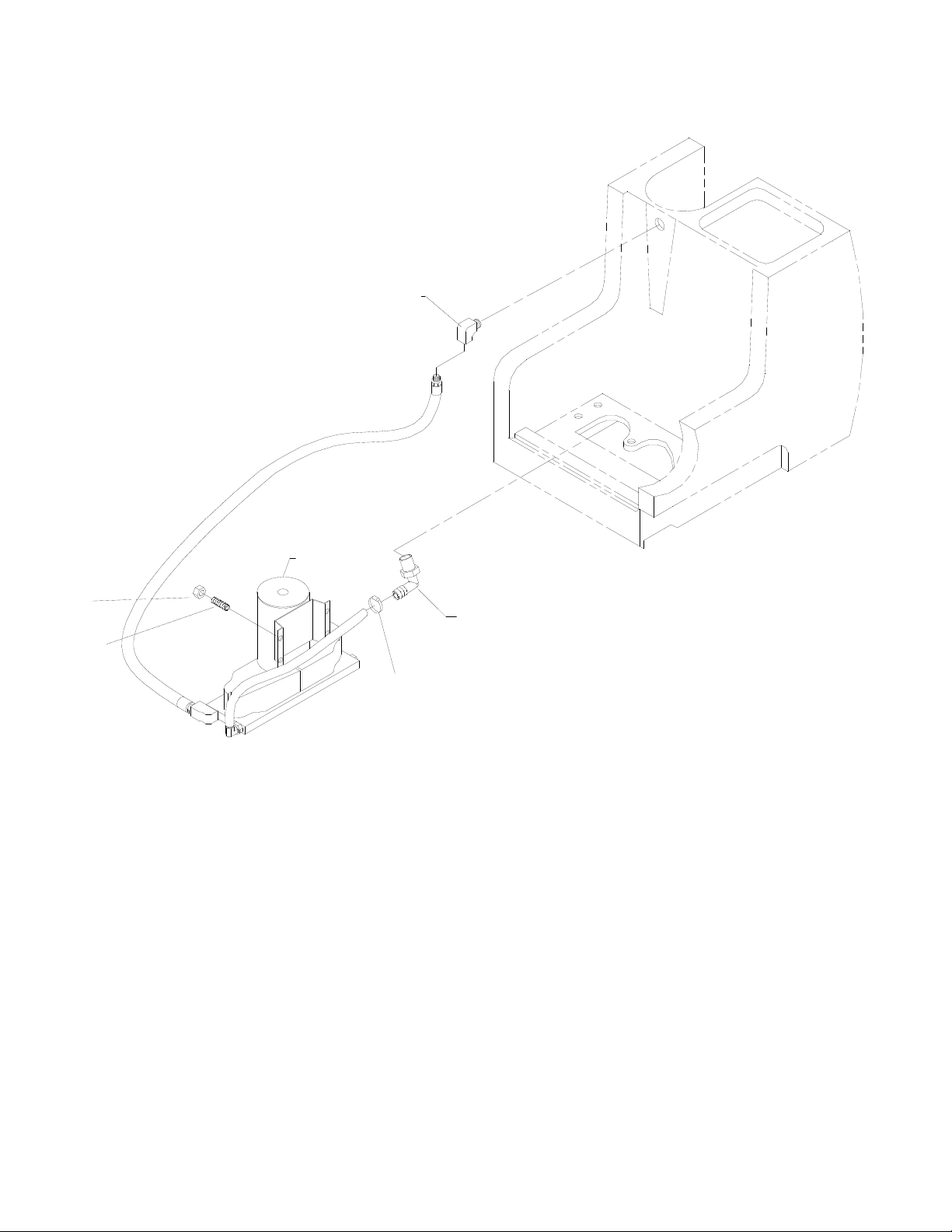
PUMP GROUP (200 PSI)
1
6
2
3
4
5
5-9
STORMCHASER 86038660 03/29/07
Page 29
PUMP GROUP (200 PSI)
REF PART NO. PRV NO. QTY DESCRIPTION
1 86199640 030-16 1 ELBOW, 1/4 NPT STREET LONG 90D
2 86006850 70393 2 SET SCR, 1/4-20 X 1.25L
3 86005710 57105 2 NUT, 1/4-20 HEX W/ STAR WASHER
4 86222770 20042 1 CLAMP, 3/8 HOSE (D-SLOT)
5 86197940 40027 1 HOSEBARB, 3/8 MPT X 1/2 90º DL
6 86201210 65209 1 PUMP ASM, 200PSI N/H D.B.
SERIAL NO.
FROM
NOTES:
STORMCHASER 86038660 03/29/07
5-10
Page 30
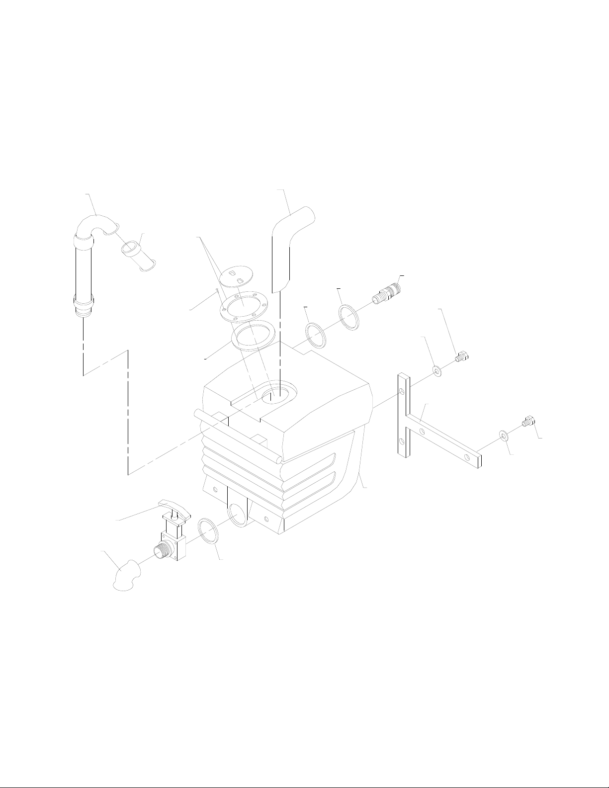
RECOVERY TANK GROUP
5
4
2
1
13
16
3
14
12
9
15
11
10
9
5-11
8
6
7
14
STORMCHASER 86038660 03/29/07
Page 31
RECOVERY TANK GROUP
REF PART NO. PRV NO. QTY DESCRIPTION
1 86033260 05151 1 TUBE ASM, RECOVERY TANK
2 86002620 260-64A 1 ACCESS COVER CLEAR 6” W/RIM
3 86275800 70546 6 SCR, 8 X 3/4 PFHT/S BLK ZINC
4 86199840 090-12A 1 FLOAT CAGE ASSY COMPLETE SLIP
5 86033330 78475 1 VAC STACK ASM
6 86161460 15-808123 1 DUMP VALVE, 2”
7 86161470 11-800444 1 ELBOW, 2” 45D PVC SCH40
8 86033420 75334 1 TANK, RECOVERY DB DK GREY
9 86010630 87013 4 WASHER, 1/4 ID X 5/8 OD SS
10 86273780 70015 2 SCR, 1/4-20 X 3/4 HHCS SS
11 86091150 065-25 1 TANK BRACE ASM, D/B
12 86273830 70020 2 SCR, 1/4-20 X 1/2 HHCS SS
13 86200290 260-33 1 HOSEBARB, 1.5MPT X 1.5
14 86237770 35256 2 GASKET, DUMP VALVE
15 86004000 35255 1 GASKET, TANK LID
16 86090320 87257 1 WASHER, HOSEBARB
SERIAL NO.
FROM
NOTES:
STORMCHASER 86038660 03/29/07
5-12
Page 32
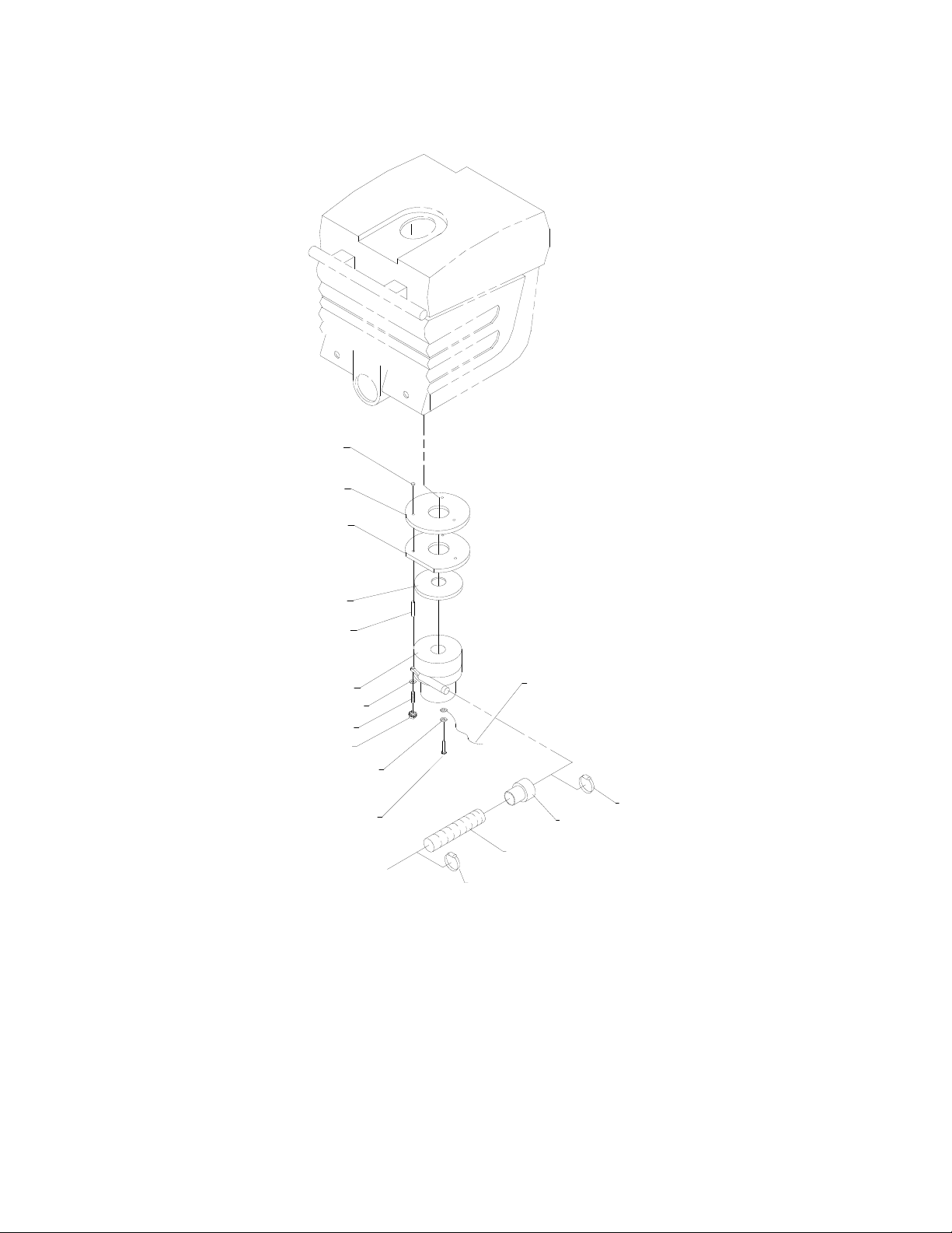
VACUMM GROUP (UPPER)
1
2
3
5
6
16
7
4
8
9
10
11
15
14
13
12
5-13
STORMCHASER 86038660 03/29/07
Page 33
VACUUM GROUP (UPPER)
REF PART NO. PRV NO. QTY DESCRIPTION
1 86201510 390-26 3 SPACER NYLON 1/4 ID X 1/2 OD
2 86237440 35168 1 GASKET, VAC BRACKET
3 86090970 360-24 1 PLATE, VAC MTR
4 86010630 87013 3 WASHER, 1/4 ID X 5/8 OD SS
5 86003760 35166 1 GASKET, VAC MTR
6 86201970 065-92 3 VAC SPACER 2 1/4 II STAGE
7 86031620 85047 1 VAC MTR ASM, D/B RCVRY 115V 2ST
- 86202070 360-04B - BRUSHES, VAC FOR 116392-00 SERVICE ONLY
- 86135320 140687 - BRUSH SET, 120V VAC WINDSOR 1000121568 SERVICE ONLY
8 86211180 70814 3 STUD, 1/4-20 X 4.5
9 86010640 87016 1 WASHER, #10 LOCK EXT STAR
10 86274980 70335 1 SCR, 10-32 X 1/2 PHTR GRN/GRND
11 86002390 20063 1 CLAMP, 1.75” WORM GEAR X .312
12 86004190 39337 1 HOSE, 1.5 BLK VAC, 24”
13 86234900 27508 1 CUFF, VAC HOSE BLU
14 86002380 20046 1 CLAMP, 2.25” WORM GEAR
15 86267480 880292 1 WIRE, 4” GRN/14 76010 X 76014
16 86005710 57105 3 NUT, 1/4-20 HEX W/ STAR WASHER
SERIAL NO.
FROM
NOTES:
STORMCHASER 86038660 03/29/07
5-14
Page 34
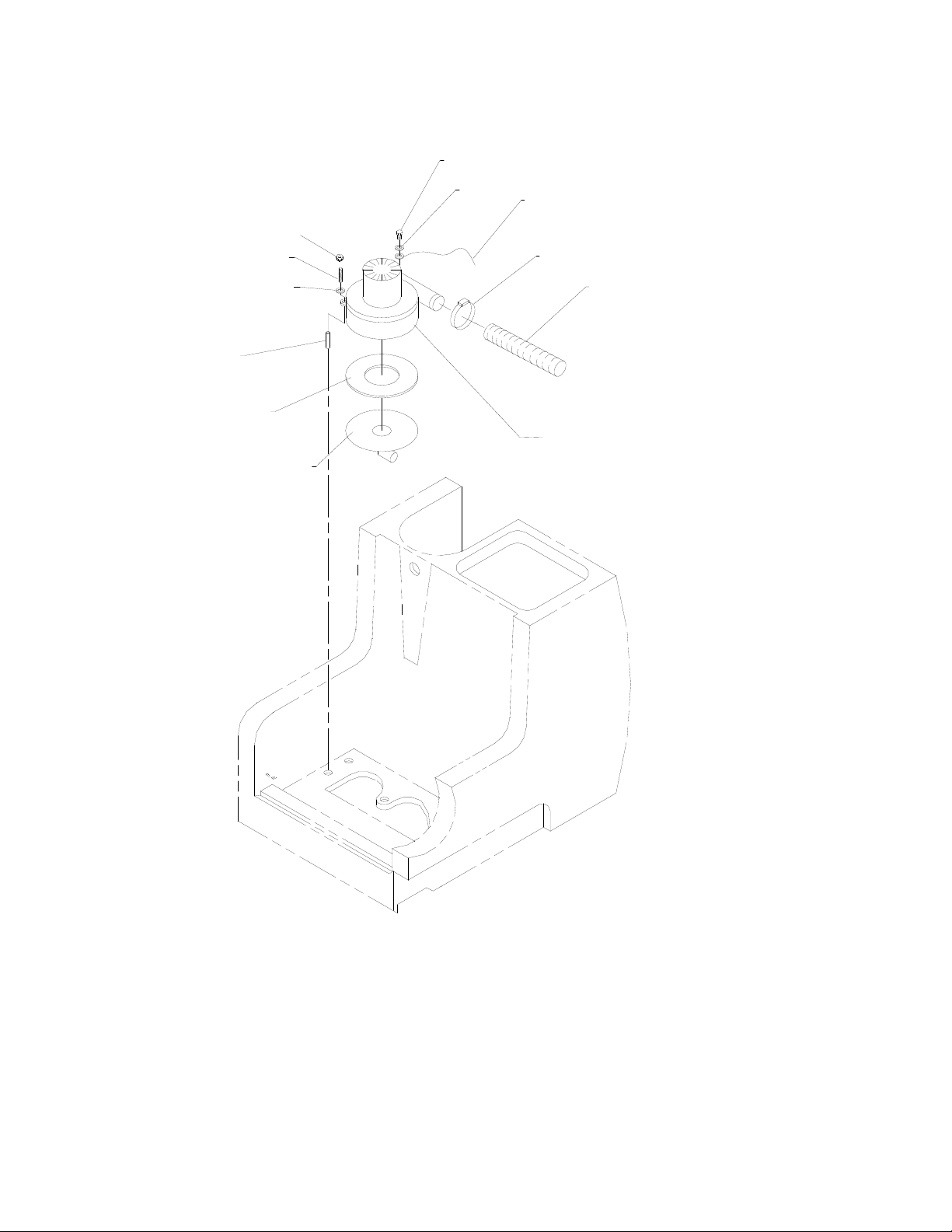
VACUMM GROUP (LOWER)
1
11
12
2
3
4
5
6
10
9
8
7
5-15
STORMCHASER 86038660 03/29/07
Page 35
VACUUM GROUP (LOWER)
REF PART NO. PRV NO. QTY DESCRIPTION
1 86274980 70335 1 SCR, 10-32 X 1/2 PHTR GRN/GRND
2 86256480 70813 3 STUD, 1/4-20 X 3.5 SS
3 86010630 87013 3 WASHER, 1/4 ID X 5/8 OD SS
4 86201970 065-92 3 VAC SPACER 2 1/4 II STAGE
5 86003760 35166 1 GASKET, VAC MTR
6 86090980 360-24A 1 PLATE ASM, VAC 90 DEG
7 86031600 85045 1 VAC MTR ASM, D/B SLTN 115V 2ST
- 86202070 360-04B - BRUSHES, VAC FOR 116392-00 SERVICE ONLY
- 86135320 140687 - BRUSH SET, 120V VAC WINDSOR 1000121568 SERVICE ONLY
8 86282120 39582 1 HOSE, VAC EXHAUST X 9”
9 86002380 20046 1 CLAMP, 2.25” WORM GEAR
10 86268220 88208 1 WIRE, 21” GRN/14 76001 X 76010
11 86010640 87016 1 WASHER, #10 LOCK EXT STAR
12 86005710 57105 3 NUT, 1/420 HEX W/ STAR WASHER
SERIAL NO.
FROM
NOTES:
STORMCHASER 86038660 03/29/07
5-16
Page 36
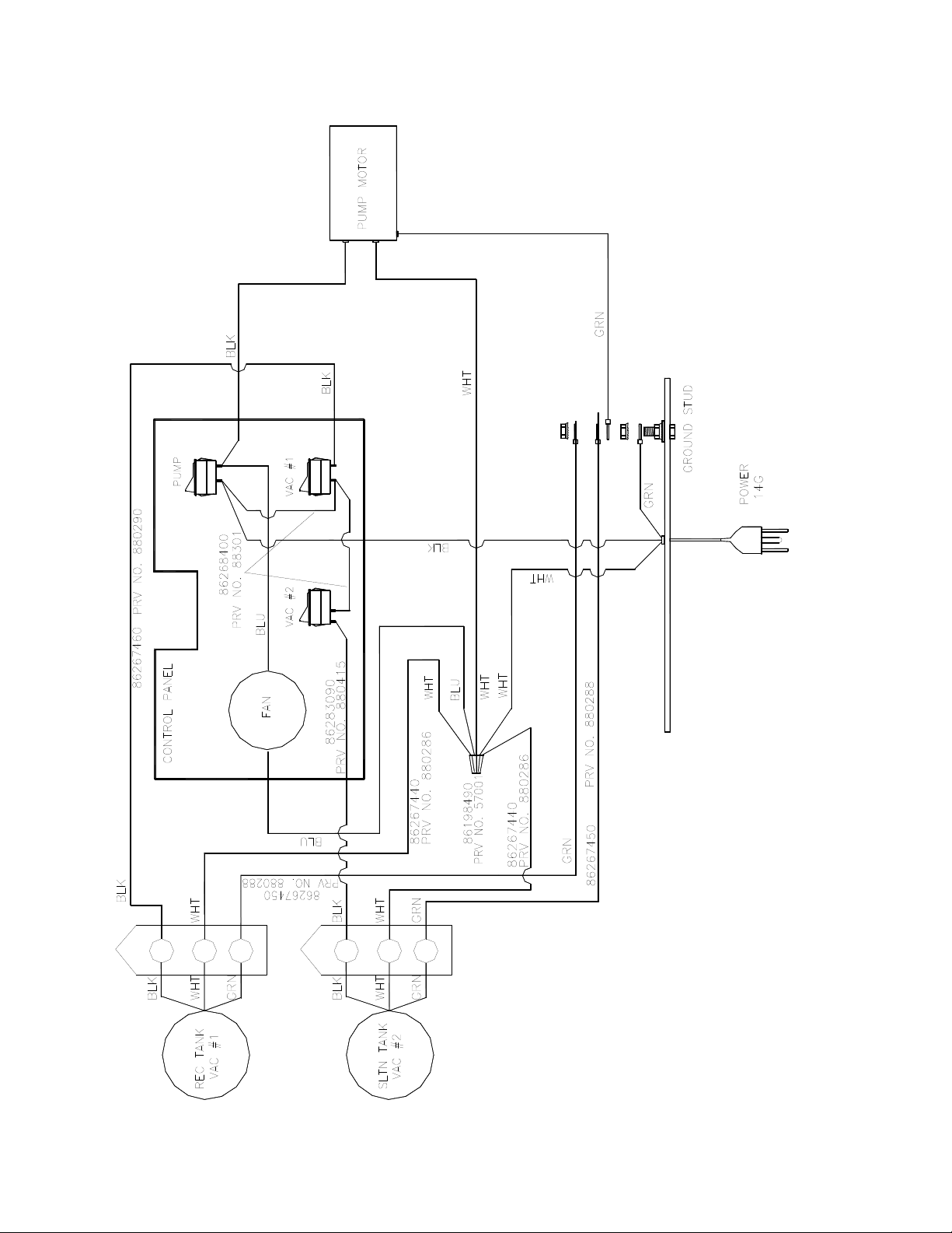
WIRING DIAGRAM (100 PSI)
5-17
STORMCHASER 86038660 03/29/07
Page 37
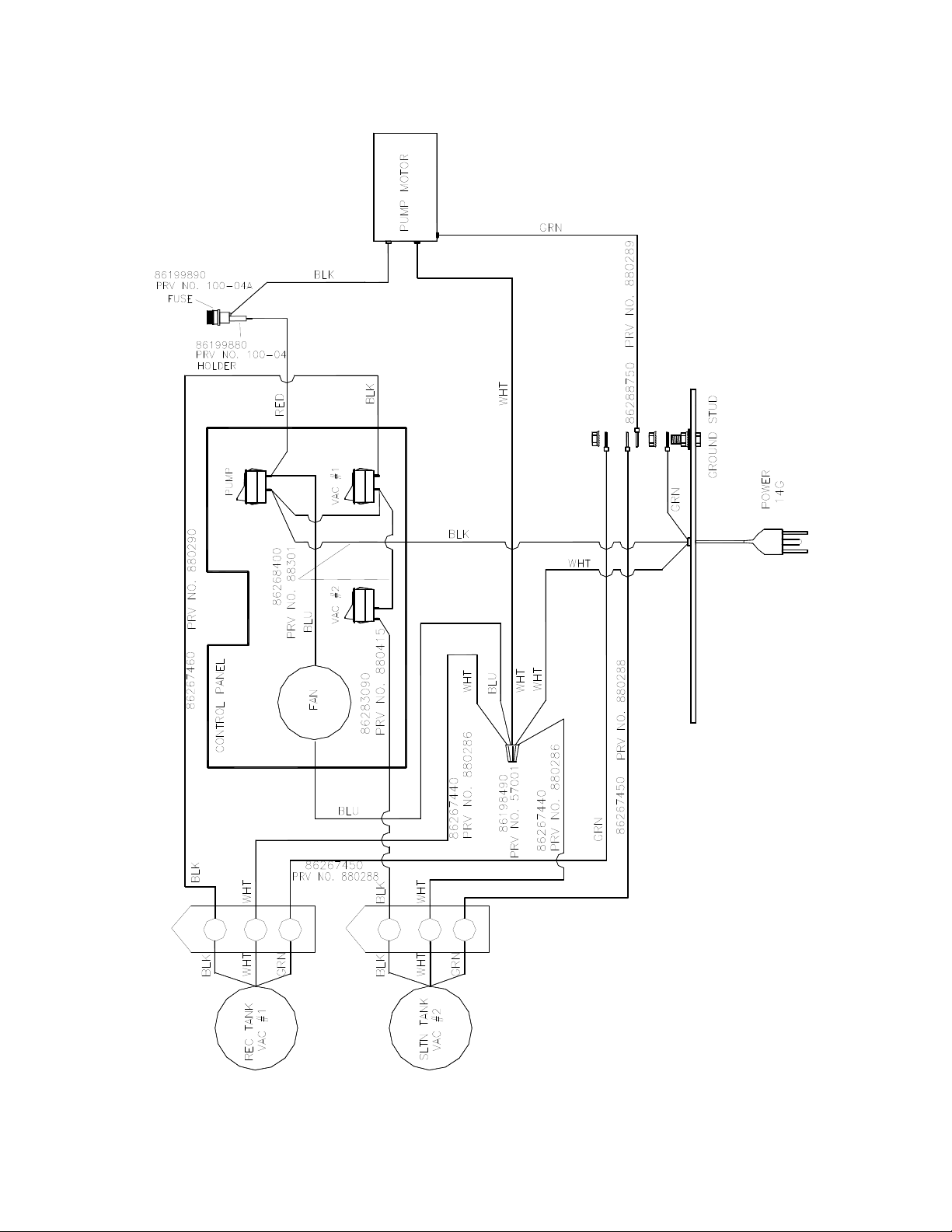
WIRING DIAGRAM (200 PSI)
STORMCHASER 86038660 11/05/09
5-18
Page 38
SUGGESTED SPARE PARTS
PART NO. PART NO. DESCRIPTION
86199880 100-04 FUSE HOLDER INLINE 200 PSI
86199890 100-04A FUSE 3 AMP 200 PSI
86197840 31032 ELBOW, 1.5 FS X FS 45D PVC
86256960 72142 ROCKER SWITCH 2 PRONG WAS 330-02
86202160 320-05 VELCRO STRAPS
86199840 090-12A FLOAT CAGE ASSY COMPLETE SLIP
86002620 260-64A ACCESS COVER CLEAR 6” W/ RIM
86251110 65219 PUMP, 115V 100PSI BYPASS W/SW (FLOJET) 100 PSI ONLY
86201210 65209 PUMP ASM, 200PSI N/H DB 200 PSI ONLY
86031600 85045 VAC MTR ASM, D/B SLTN 115V 2ST 100 PSI ONLY
86031620 85047 VAC MTR ASM, D/B RCVRY 115V ST 200 PSI ONLY
86202070 360-04B BRUSHES, VAC FOR 116392-00
86135320 140687 BRUSH SET, 120V VAC WINDSOR 1000121568
86201430 250-64A SHURFLO 100 PSI PUMP DEMAND 100 PSI ONLY
SERIAL NO.
FROM
NOTES:
5-19
STORMCHASER 86038660 03/29/07
 Loading...