

Page 1
DES-MAN ISS.3
Page Section Contents
1 i) Introduction and Factory Defaults
2 ii) Installation Instructions
iii) Electrical and Data Connections; Circuit Schematic
3 iv) Code Entry Mode
v) Programming Mode
4 vi) Adding and Removing Codes
5 vii) Changing Door Strike Times
viii) Setting the Invalid Code Penalty Time
6 ix) Other Features. Remote Exit, Alarms, Relay 2,
Door Monitoring, Entry Under Duress, Alarm Signals
7 x) Code Index Directory
8 xi) Command Summary Chart
Storm AXS Strike Master Keypads provide comprehensive access control for all outdoor and
indoor locations. Door / system status is indicated by a high intensity LED light source and an
audible sounder. Storm AXS Strike Master Keypads are specified to survive in different service
environments, ranging from exposed unsupervised public locations to general service indoor
applications. Keypads in the Storm AXS Strike Master range are dimensionally and electrically
interchangeable. This allows users, entering codes at both outdoor or indoor access points, to
establish and maintain familiarity with the keypad features.
• Up to 50 user programmable
entry codes
•
Entry Code
indexing system provides a
directory of authorised code holders and
permits secure allocation and re-allocation
of
entry codes
• 4, 5, or 6 digit
entry codes
• One or two door control
• Anti-tamper alarm
•
Entry code
entered under duress alarm
• Hidden
entry code
feature
• Forced door alarm
• Timed strike or latching door operation
• Timed lock out for repeated invalid code
input
• Remote switch exit facility
• Fail (open) Fail (closed) option
• All weather resistant
• Two protection levels
– anti vandal keypad for unsupervised
public, outdoor locations
– robust keypad for
regular outdoor / indoor locations
Default settings
FEATURE FACTORY SET DEFAULT
‘Engineer’s’code 111111
(For security, change default
engineer’s code
on installation)
Door 1 ‘Strike Time’ 5 seconds
Door 2 ‘Strike Time’ 5 seconds
Invalid code Penalty time 15 seconds
Relay 2 output Set in ‘Alarms Mode’
Relay 2 Configuration Relay Output set ‘normally open’
Door Sensor Bridged. Remove wire bridge to enable this feature
The STORM AXS Strike Master Keypad is supplied with the following factory configured defaults.
t
m
r
o
Secure Keypads
for access control
®
i) INTRODUCTION AND FACTORY DEFAULTS
Strike Master
Read this manual carefully before attempting to install, program or operate the
STORM AXS Strike Master Keypad. After installation the Command Summary Chart at the
back of this manual can be used as a quick reference to programming and operating
command sequences.
Page 2
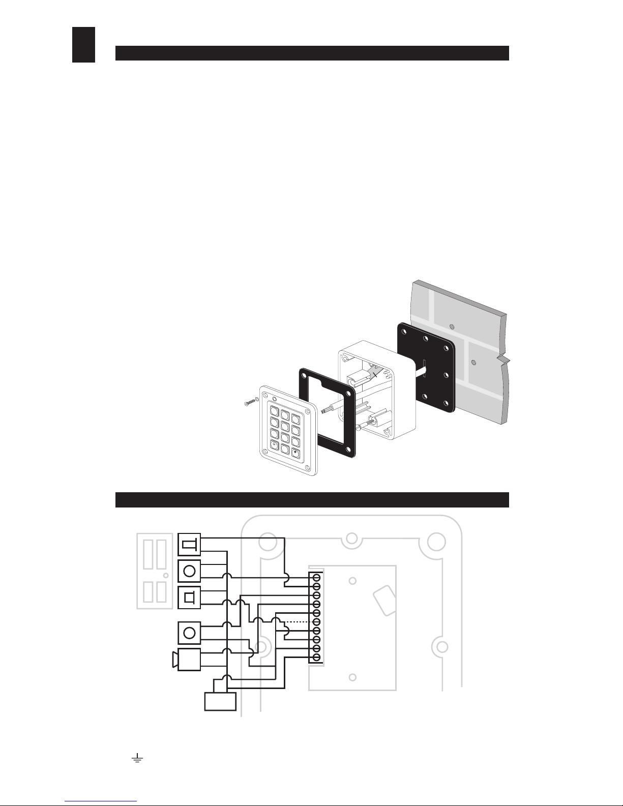
Fixing Instructions
(Please read carefully before attempting installation.)
Rear Casing
1. Select a suitable location with a sound flat surface. Using the case as a template, mark the
position of the four fixing holes (A) on the surface.
2. Drill and plug the fixing holes to suit fixing screws (E) as supplied.
3. Locate the anti-tamper switch actuator plate (F) on the rear face of the case in the position as
shown.The fixing screws (E) may be positioned in the case to assist in the accurate location of
the plate.
4. Locate the thicker (6mm) sealing gasket (B) on the rear face of the case before positioning the
case over the fixing holes (A). (Be sure to run the cable through the hole in the gasket prior to
securing the case.)
5. Secure the case to the surface using the fixing screws (E) as supplied.
Keypad to Casing
6. When making the electrical connections to the connector block care should be taken not to
damage the thin sealing gasket (C) fixed to the front face of the rear case. [For connection details
see section iii) of this manual.]
7. Fix the keypad to the rear case using the thread forming
security screws (D) as supplied. (Please ensure the nylon sealing
washers are located beneath the head of the security screws (D).
Please note a special bit is provided for tightening these screws.
8. Check the installation to ensure gaskets are in place and
compressed evenly around the perimeter of the case.
Note: On rough or uneven surfaces it
may be necessary to apply a
bead of silicone sealant
around the inner face of the
case at the point where it
meets the mounting surface.
Where this method of sealing
is necessary the thicker
sealing gasket (B) must not
be fitted.
ii) INSTALLATION INSTRUCTIONS
2
Door Sensor
Remote/
Exit Switch
Door
Strike
Door/call Bell
Alarm Bell/
Klaxon
Power
Supply
10. Remote Switch - To open door 1 from within secure area
9. Door Sensor - Used to monitor door 1 condition (open/closed)
8. Door/Call Bell - Open collector gate
7. Alarm/Door 2 Release Relay - Fully floating (volts free contact)
5. Door 1 Release Relay - Relay output (normally closed)
4. Common - Relay common
3. Door 1 Release Relay - Relay output (normally open)
2. Supply - Range 11 to 28 volts dc or 9 to 20 volts ac.
1. Return - Zero volts
6. Alarm/Door 2 Release Relay - Fully floating (volts free contact)
+V 0V
iii) ELECTRICAL AND DATA CONNECTIONS
Note:When making connection to the door strike, select ‘relay normally open’or ‘relay normally closed’ to suit the intended application and locking mechanism.
Note: To achieve maximum protection against EMC, RFI, or damage from Electro-static Discharge it is recommended that the keypad
casing is earthed (grounded) via the screw terminal attached to the metal shield on the rear face of the keypad.This terminal is identified
by a symbol. It is recommended that a regulated, fully isolated power supply is used to power the StrikeMaster keypad.
(Keymat Technology part no. DEPS0101 or DEPS0201 or equivalent). Bifular wound supplies are not recommended.
1
3
2
6
5
4
7
9
8
0
A
B
C
D
E
F
DES-MAN ISS.3
Page 3
Start new
command sequence
Enter to d
1 8
Enter new 6 digit
Engineer's Code
Enter d
To select new
Engineer's Code
Enter d
Enter
Engineer's Code
If code is not known
'Power Down'
then Power Up
LOG OFF?
X X X X X X
Enter
to log on
7 2 5
4
0 0
X X X X X X
Enter d
0
YES
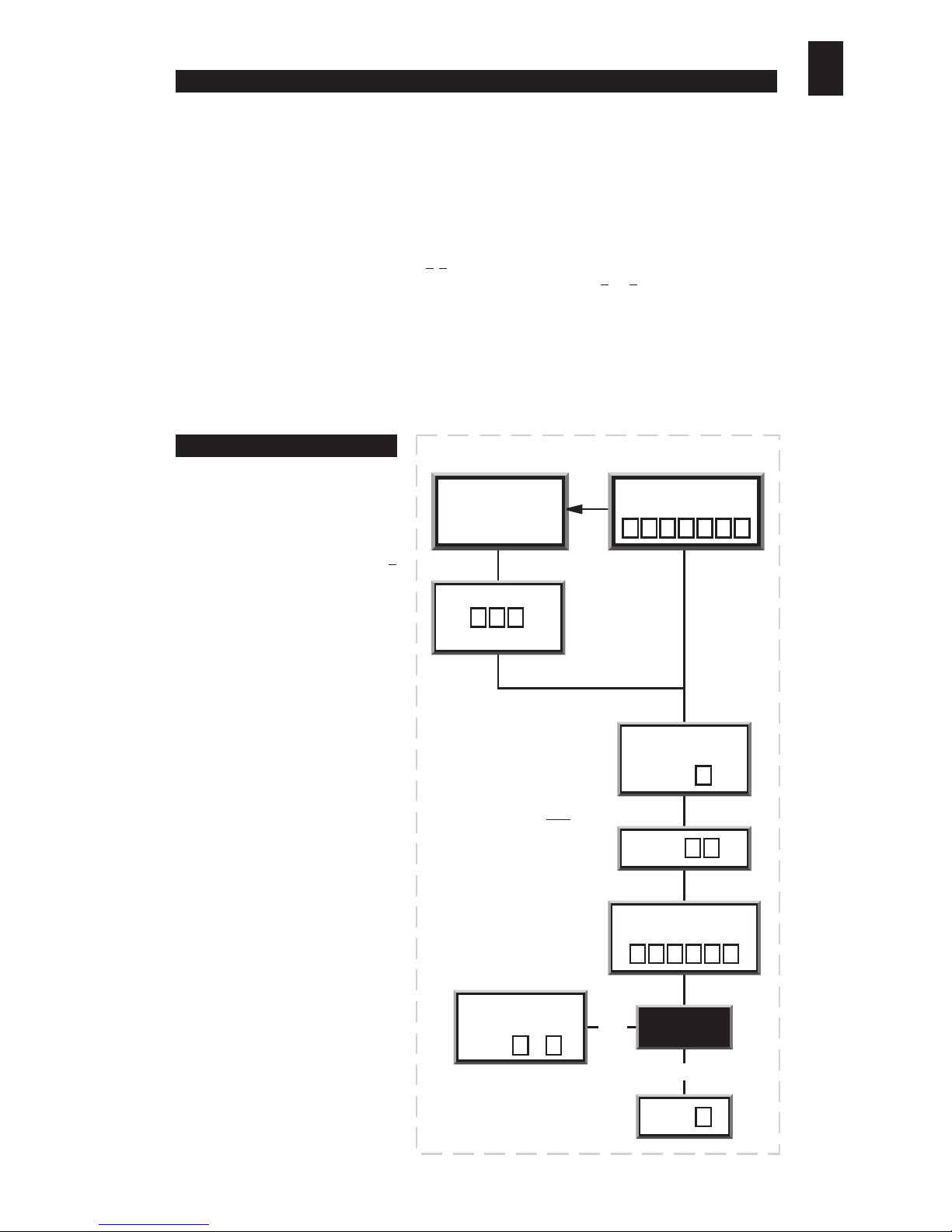
RE-ALLOCATE ENGINEER'S CODE
NO
#
To enter
programming mode
it is
required that the operator
‘logs on’
by entering the
engineer’s code
.
When logging on the
engineer’s
code
must be preceded by the #
key. If the code is correct the LED
will start flashing (red and green
alternately) to signify that the
operator has logged on and that
the keypad is in
programming
mode
ready to accept commands.
For security reasons it is essential
that the default
engineer’s code
is
replaced with your own six digit
code.Please ensure a record of the
code is kept in a secure place.
If the
engineer’s code
is not known, power down the keypad
for a period of not less than three seconds.Po wer up the ke ypad
and within a two minute period enter the code 725.
Do not enter any other digits before entering this code. The
keypad’s LED will then begin flashing to indicate that the keypad
is in
programming mode
. Install a new
engineer’s code
;
(Refer to the chart on this page)
Once in
programming mode
the operator can use the
commands, as summarised in Sections v) - viii) to set up the
keypad. After each segment of a command sequence is entered
the keypad will give a rising tone
bleep to indicate that it has accepted
the data and is ready for the next
segment of the command. If at any
stage the keypad gives an error b leep
(decreasing pitch) then the data
entered is invalid. The keypad will
remain in
programming mode
but
you must re-enter the whole of the
command sequence within which the
error bleep occurred.
During everyday operation the keypad will be in
code entry
mode or
‘logged off’
.This is also the
mode that the keypad is in when it is first powered up. When the keypad is in
code entry
mode
the LED will light red to signify that the keypad is waiting for either an
entry code
or the
engineer’s code
to be entered.
When entering a code, spurious digits may be entered before and after the valid code to help
disguise it from onlookers or other surveilance (maximum 20 characters to be entered at any one
time). [Care should be taken not to activate the
Operator Under Duress
alarm by prefixing
a valid
entry code
with the numbers 9 1.
[see section ix) - Activating the Operator Under
Duress Alarm]. Entry codes
should not begin with the numbers 9 or 1 as this can also lead
to non intentional triggering of the
Operator Under Duress Alarm. [see section vi) - Adding
and Removing Codes].
]
When a valid
entry code
has been entered the door strike will release for the period of the
strike
time [see section vii) - Setting the Door Strike Time]
or latch open, depending on what type
of code was entered
[see section vi) - Adding and Removing Codes]
.The LED will light green
to signify that the door lock is in a released (or open) condition.
iv) CODE ENTRY MODE
v) PROGRAMMING MODE
3
DES-MAN ISS.3
Page 4
Notes:
a).
Entry Codes
should not start with numbers 9 or 1.
b). Each
entry code
recognised by the keypad is stored under a two digit reference known as the
Code Index
Number
.The
code index number
allows an authorised holder of the
engineer’s code
to remove
entry codes
by keying in the
code index number
without having knowledge of the actual
entry code
. It also means that a
written record of valid code holders can be kept without recording the actual
entry codes. [see section x) -
Code Index Directory].
c). Prior to operation of a second door, relay 2 must be set for door control.
[see section ix) - Contolling a
Second Door].
vi) ADDING AND REMOVING CODES
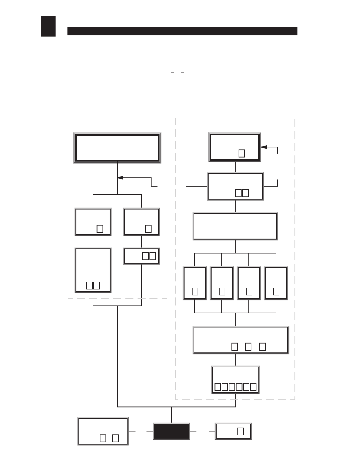
To add an
entry code
Enter the 2 digit
index number (max 50)
Select door
and mode of entry required
for this entry code
Door 1
Timed
Enter
Door 1
Latched
Enter
Door 2
Timed
Enter
Door 2
Latched
Enter
Enter 4,5 or 6 to correspond
to no. of digits in code
Enter (4) or (5) or (6)
Enter
new code
There are 2 options for
removing codes - remove a single
code or remove all codes
Remove an
Index Field
Enter d
Remove all
Index Fields
Enter d
Enter Index
number from
which code is
to be removed
Enter
REMOVING CODES ADDING CODES
2 3
Enter d
0 0
Enter d
1
Enter d
1 2 3 4
4 5 6
X X X X X X
Start new
command sequence
Enter to d
1 8
LOG OFF?
NO
Enter d
0
YES
Index
allocated
- delete
fields
Index
allocated
- try another
Index No.
X X
X X
4
DES-MAN ISS.3
To add or remove
entry codes ‘log on’,
then follow the appropriate command sequence
detailed below.
Page 5
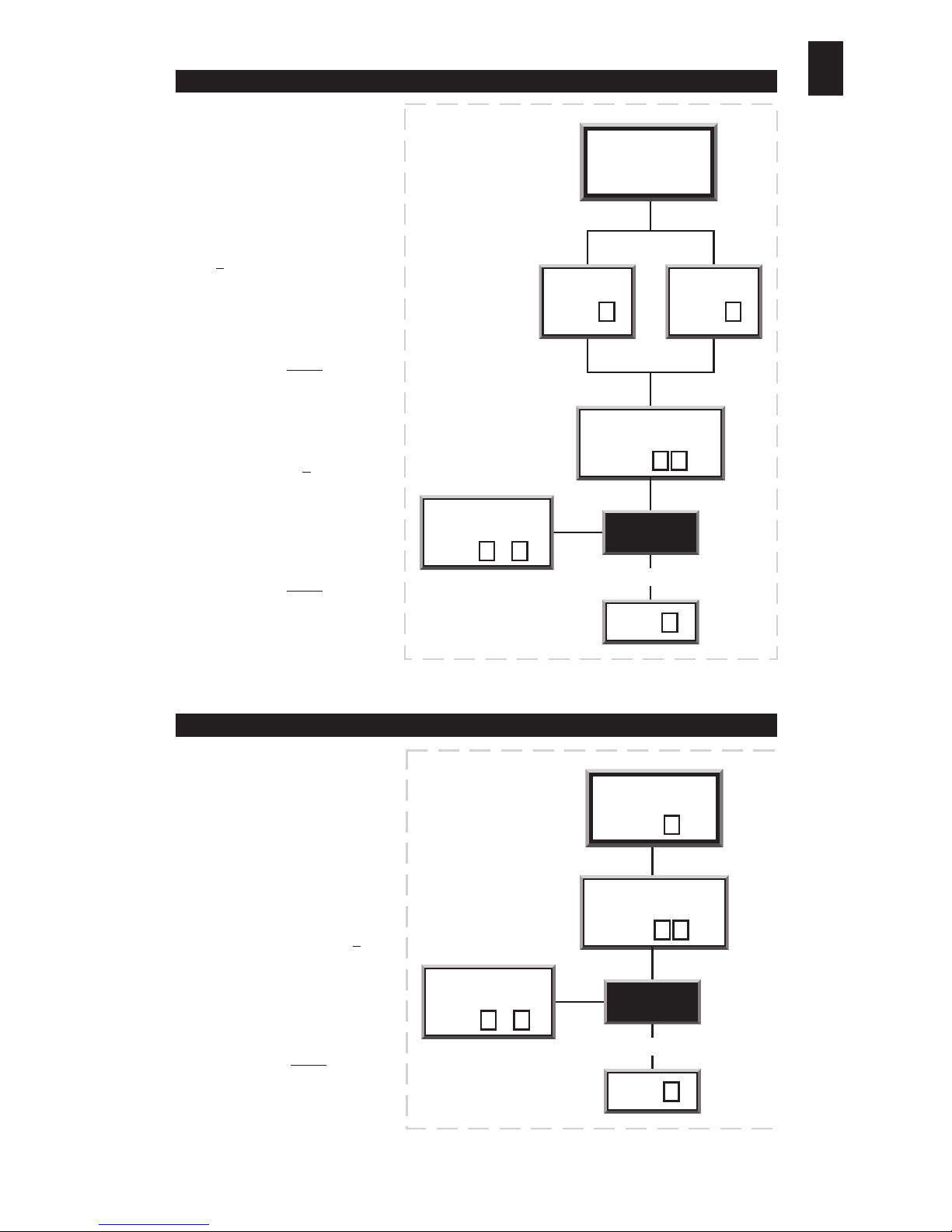
I) Setting the Door 1
‘Strike Time’
The door
strike time
is the
number of seconds for which
the door lock remains released
(or open) when a valid
entry
code
is entered. To set the
Door 1 strike time,
‘log on’
, then
enter 5 to select the
Door 1
Strike Time Set Up
function.
Listen for the ‘accept bleep’
Then enter a two-digit number
to set the duration of the
strike
time
in seconds (00-99)
Listen for the ‘accept bleep’
ii) Setting the Door 2
‘Strike Time’
To set the Door 2
strike time
,
log on, then enter 6 to select
the
Door 2 Strike Time Set Up
function. Listen for the
‘accept bleep’
Then enter a two-digit number
to set the duration of the
strike
time
in seconds (00-99)
Listen for the ‘accept bleep’.
When in
Code Entry
mode, if
after twenty key presses a valid
code has not been entered, the
keypad will be disabled for a
pre-set period of time. This
feature is intended to deter any
attempt to gain unauthorised
access by guessing the format
of a valid code.
To set the
Invalid Code Penalty
Time, ‘log on’,
then enter 7 to
select the
Invalid Code Penalty
Time
function.
Listen for the ‘accept bleep’.
Then enter a two-digit number to
set the duration of the
Penalty
Time
in seconds (00-99)
Listen for the ‘accept bleep’.
Enter Strike Time
in seconds
Door 1 Door 2
To re-allocate
door
strike times
Start new
command sequence
Enter to d
1 8
LOG OFF?
Enter d
0
YES
Enter d
5
Enter d
6
Enter d
X X
To reset Invalid
Penalty Time
Enter Penalty Time
in seconds
Start new
command sequence
Enter to d
1 8
LOG OFF?
Enter d
0
YES
Enter d
7
Enter d
X X
5
vii) CHANGING DOOR STRIKE TIMES
viii) SETTING THE INVALID CODE PENALTY TIME
DES-MAN ISS.3
Page 6
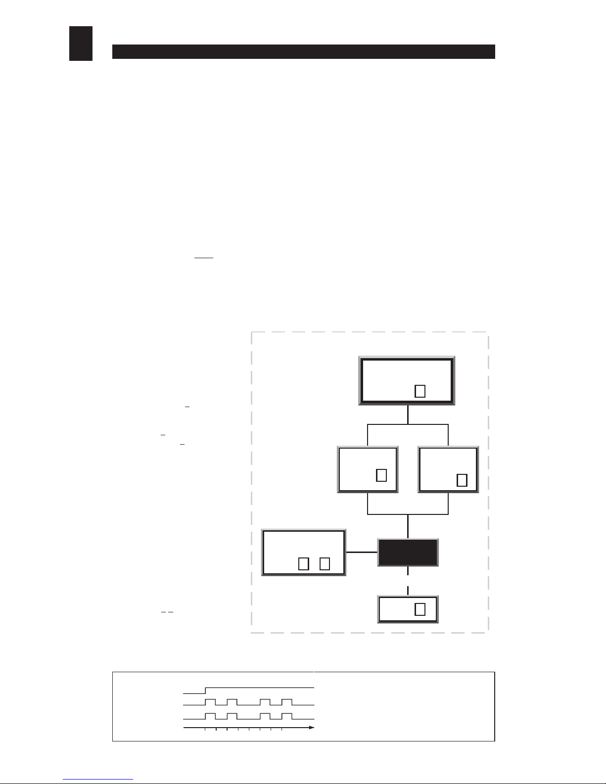
Start new
command sequence
Enter to d
1 8
LOG OFF?
Enter d
0
YES
SETTING THE ALARM / SECOND DOOR OPTION
Alarm
Second Door
Control
To select Alarm or
Second Door option
Enter d
0
Enter d
8
Enter d
1
a) The Remote Exit / Egress Switch
Making a connection (via a suitable momentary contact switch) between connector terminals 10 and 1
(return) will release (or open) the door lock for a pre-set period of time (the door
strike time
).This feature
can be used to provide a
remote exit facility
, allowing personnel to exit from a secure area by pressing
a button located near or adjacent to the door (on the secure side only).
[see sections vii) and viii) for
information about setting the door strike time]
. Please note, in 2 door operation the connection of a
remote egress switch to control the second door is not possible.
b) Alarms
An alarm bell or klaxon can be activated via connector terminals 6 and 7. When the keypad enters an
alarm state (door forced or operator under duress or anti-tamper), these two terminals will provide an
alarm signal (2 Amps max. at 30 Volts DC).The alarm bell or klaxon should be connected as shown in
section iii) - Electrical & Data Connections.
Please note that the alarm bell or klaxon is not powered
from the keypad and so must have an independent power supply.
An alarm signal can be cancelled by keying in any valid
entry code
or the
engineer’s code
. If the cause
of the alarm can be rectified (i.e.The Anti-Tamper s witch can be re-closed, or a ‘f orced door’can be closed),
then keying in a valid ‘Entry Code’ will silence and reset the alar m.
If for any reason the cause of the alarm can not be rectified (e.g.The keypad has been forced away from
the wall, or the door has been damaged and can not be closed), then the alarm can be silenced by keying
in a valid ‘Entry Code’ twice
(2 times). When the alarms have been silenced in this way, the keypad must
be isolated from the power for a minimum of 3 seconds to reset the alarm feature.
Note if the alarm function is used to indicate
operator under duress
then the alarm should be
discreet, i.e., situated in a remote location beyond the audible or visual range of an attacker or
intruder. The alarm feature can be used to interface with a centralised alarm system or to trigger
a synthesised or pre-recorded auto dial telephone message to a chosen monitoring station.
Alternatively, terminals (6 and 7) can be used to control a second door.
[Refer to section ix) c) - Controlling a Second Door].
c) Controlling a Second Door
(one keypad controls access
through two doors)
Connector terminals 6 and 7 can be
used as a relay output to control a second door. When the
keypad is used for
second door control
the
Alarms
feature will
be disabled. To configure the keypad for
second door control,
‘log on’,
then enter 8 to select
Relay 2 Set Function.
Listen for
the ‘accept bleep’.
Then enter 1
to configure the relay for
second door
control
, or enter 0 to re-configure the relay as an alarm
output. Listen for the ‘accept bleep’.
(Refer to chart opposite)
d) Door Monitoring (Door 1 only)
In its factory fitted format, the door sensor is disabled.This
is because the hard wire bridge is connected between
terminals 9 and 1 (0V Return and the Door Sensor).
This disables the
door forced alarm
feature. To utilise the door sensor,
remove the hard wire bridge and
connect the door sensor to terminals
1 and 9.
e) Activating the ‘Operator Under
Duress’ Alarm
The
Operator Under Duress Alarm
can be activated at any time by prefixing a v alid
entry code
with
the numbers 9
1. Note: if there is any possibility that this feature
will be used, any visible or audible alarm indicators must be
located out of audible and visual range of any attacker or
intruder.
[Refer to section ix) b) - Alarms].
f) Alarm Output Signal
FEATURE SIGNAL COMMENTS
Duress
Relay does not oscilate; stays silent
so as not to alert intruder
Door Forced
Anti Tamper
ix) OTHER FEATURES
6
DES-MAN ISS.3
01234567 time (secs)
Page 7
Engineer’s Code
Door 1 ‘Strike Time’
Door 2 ‘Strike Time’
Invalid Code Penalty Time
Relay 2 Output
Relay 2 Configuration
00
01
02
03
04
05
06
07
08
09
10
11
12
13
14
15
16
17
18
19
20
21
22
23
24
25
26
27
28
29
30
31
32
33
34
35
36
37
38
39
40
41
42
43
44
45
46
47
48
49
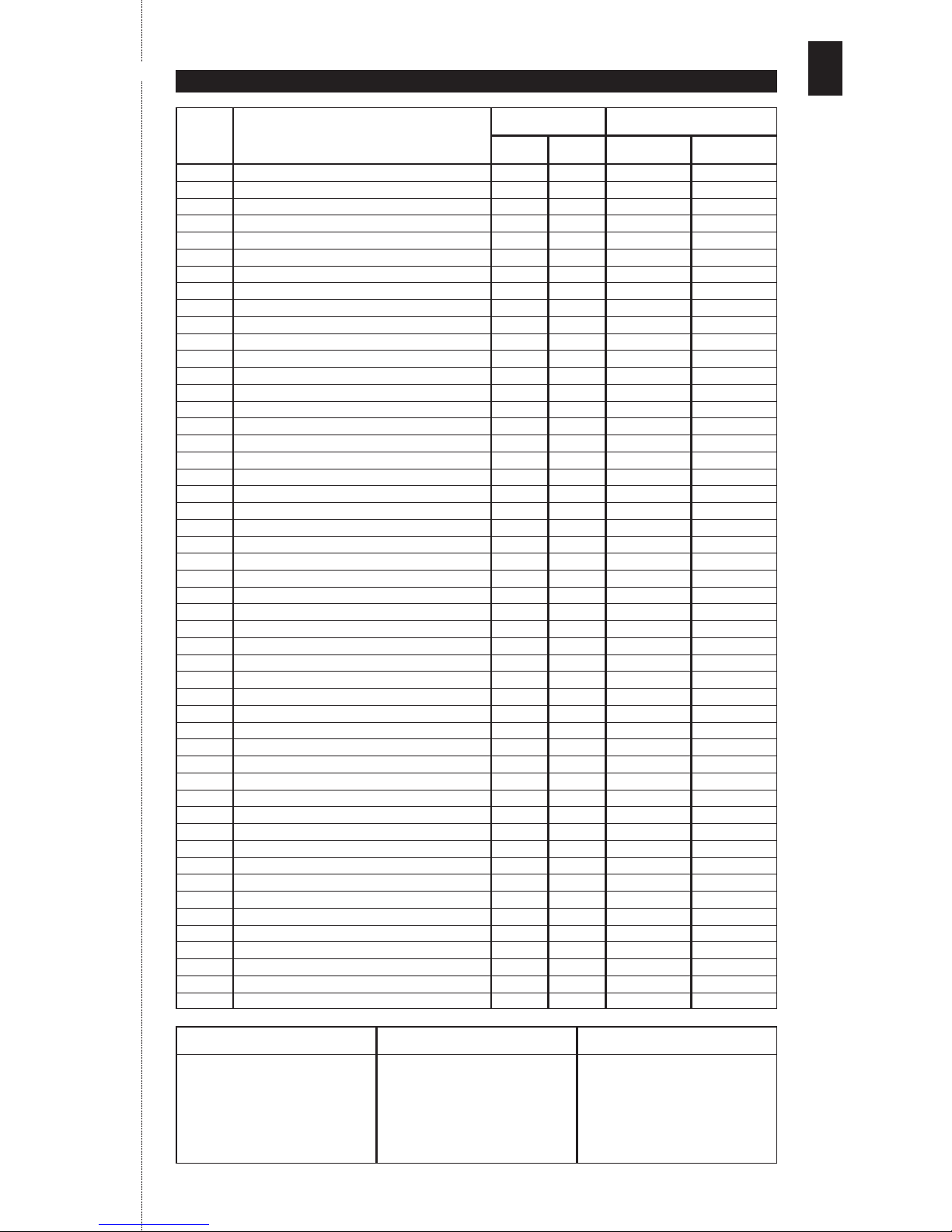
CODE
INDEX
NO.
CODE HOLDER
NAME OF PERSON/DEPARTMENT
x) CODE INDEX DIRECTORY
DOOR TYPE OF CODE
FEATURE
111111 (change on installation)
5 seconds
5 seconds
15 seconds
Alarms Mode
Normally Open
(record separately in safe location)
FACTORY SET DEFAULT OWNER SET CODES
1 2 LATCHED TIMED
✁
7
DES-MAN ISS.3
Page 8
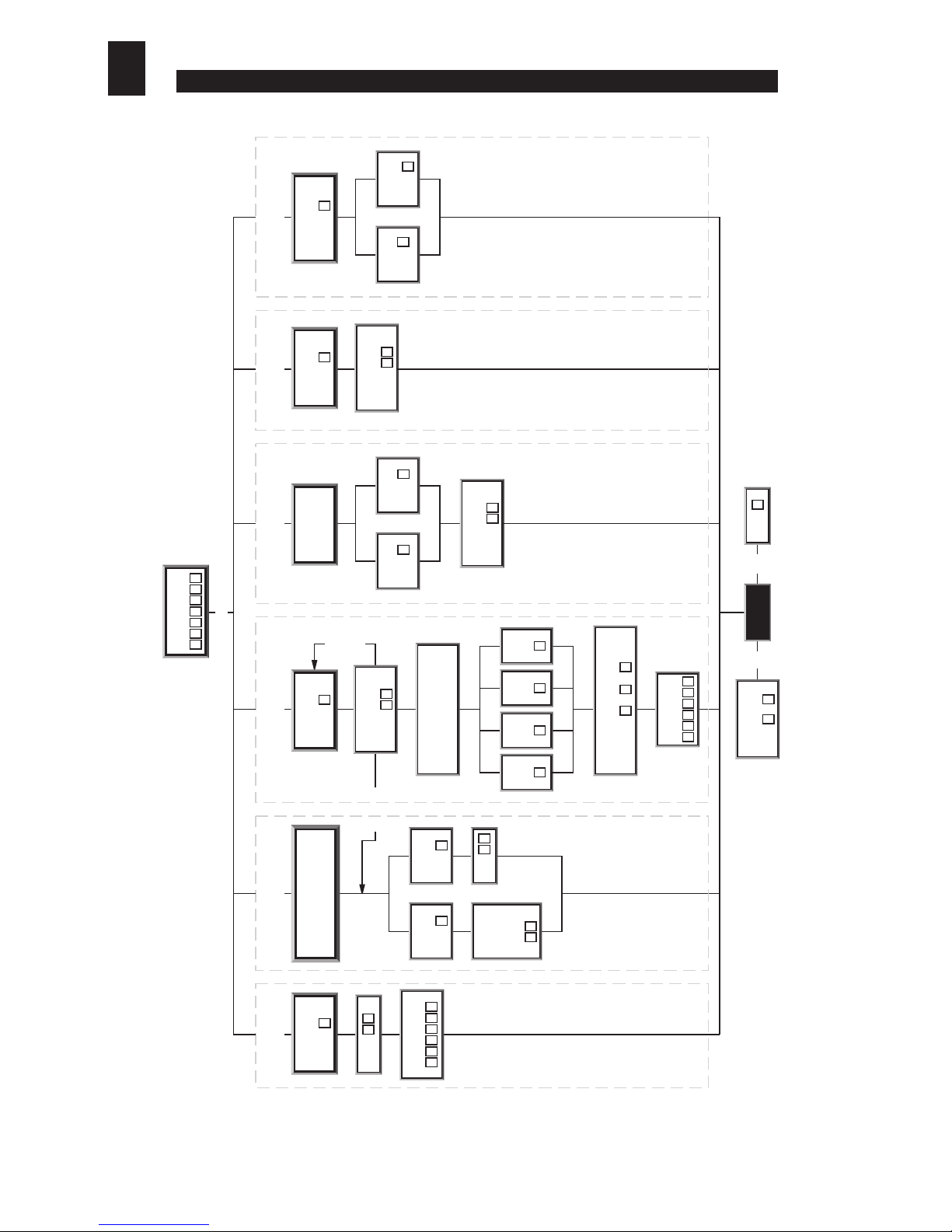
8
(Detailed explanation of command sequences are located in sections v) to ix).
DES-MAN ISS.3
Whilst every effort is made to ensure that information given in this document is correct at time of print, Keymat Technology Ltd. can not
be held responsible for any errors contained within.
STORM , AXS, STRIKE MASTER & CODE MASTER are trademarks of Keymat Technology Ltd, England.
v) RE-ALLOCATE
ENGINEER'S CODE
To add an
Entry Code
Enter the 2 digit
index number (max 50)
Select door
and mode of entry required
for this entry code
Door 1
Timed
Enter
Door 1
Latched
Enter
Door 2
Timed
Enter
Door 2
Latched
Enter
Enter 4,5 or 6 to correspond
to no. of digits in code
Enter (4) or (5) or (6)
Enter
new code
There are 2 options for
removing codes - remove a single
code or remove all codes
Remove an
Index Field
Enter d
Remove all
Index Fields
Enter d
Enter Index
number from
which code is
to be removed
Enter
vi) REMOVING CODES vi) ADDING CODES
2 3
Enter d
0 0
Enter d
1
Enter d
1 2 3 4
4 5 6
X X X X X X
Start new
command sequence
Enter to d
1 8
LOG OFF?
NO
Enter d
0
YES
Index
allocated
- delete
fields
Index
allocated
- try another
Index No.
Enter Strike Time
in seconds
Door 1 Door 2
To re-allocate
door
stike times
vii) CHANGING
DOOR STRIKE TIMES
Enter d
5
Enter d
6
Enter d
X X
To reset Invalid
Penalty Time
Enter Penalty Time
in seconds
viii) SETTING THE
INVALID PENALTY TIME
Enter d
7
Enter d
X X
ix) SETTING THE ALARM/
SECOND DOOR OPTION
Alarm
Second Door
Control
To select Alarm or
Second Door option
Enter d
0
Enter d
8
Enter d
1
Enter
Engineer's Code
X X X X X X
If unkown refer to Programming Mode / Section v)
#
Enter new 6 digit
Engineer's Code
Enter d
0 0
X X X X X X
To select new
Engineer's Code
Enter d
4
X X
X X
xi) COMMAND SUMMARY CHART
 Loading...