

Page 1
MAINTENANCE MANUAL
STORM Century S-LSA
STORM Century S-LSA STORMAIRCRAFT
MAINTENANCE MANUAL
AIRCRAFT
STORM Century S-LSA
SERIAL N°
CLASS
STORMAIRCRAFT
DATE : 11-14-2005
SEVICE BULLETIN
STORM Century S-LSA
This manual contains all the information concerning maintenance and periodic overhauls as
suggested by STORMAIRCRAFT
This manual contains PROJECT DATA AND DRA26 PSIS which are exclusive property of
STORMAIRCRAFT. No part of this manual shall be: divulged, reproduced or transmitted in
any way and by no electronically or manual mean, including photocopies and recordings,
for no purpose without the written consent of STORMAIRCRAFT
Page 2
MAINTENANCE MANUAL
STORM Century S-LSA
STORM Century S-LSA STORMAIRCRAFT
INDEX
1 GENERAL 1.1
1.1 Equipment list 1.2
1.2 Sources to purchase parts 1.8
1.3 List of disposable replacement parts 1.9
1.4 Engine specifications 1.10
1.5 Weight and balance information 1.12
1.6 Tire inflation pressure 1.16
1.7 Approved oils and capacities 1.16
1.8 Recommended fastener torque values 1.17
1.9 General safety information 1.21
1.10 Transmitting safety of flight concerns to STORMAIRCRAFT 1.24
2 INSPECTIONS 2.1
2.1 Power check 2.3
2.2 Engine compartment 2.4
2.3 Engine 2.5
2.4 Propeller 2.6
2.5 Cockpit 2.7
2.6 Surface and structure check 2.9
2.7 Landing gear 2.10
2.8 Fuselage-Airframe-Cockpit inspection 2.11
2.9 Engine-Nacelle-Landing gear inspection 2.12
2.10 Wing-Stabilizer-propeller-radio set inspection 2.13
2.11 Airworthiness prescriptions and power check 2.14
2.12 System and Avionics maintenance 2.15
2.13 Functional test 2.16
2.14 Daily Inspection 2.18
3 STRUCTURES 3.1
3.1 Description of flight controls 3.1
3.1.1 Flight controls inspection 3.2
3.1.2 Flap Control 3.3
3.2 Removal-Installation 3.4
3.2.1 Wing 3.4
3.2.2 Flap 3.6
3.2.3 Aileron 3.9
3.2.4 Rudder 3.11
3.2.5 Rudder cables 3.14
3.2.6 Stabilator 3.16
3.2.7 Trim control 3.21
3.3 Control stop and regulation 3.23
3.3.1 Lubrication and controls check 3.24
3.4 Landing gear 3.24
3.4.1 Landing gear and brake system faults 3.25
3.4.2 Main landing gear removal 3.25
3.4.3 Brake system 3.28
3.5 Steerable nose gear 3.30
3.5.1 Steerable nose gear removal 3.31
3.6 Seat belts 3.34
Page 3
MAINTENANCE MANUAL
STORM Century S-LSA
STORM Century S-LSA STORMAIRCRAFT
4 ENGINE 5.1
5 FUEL SYSTEM 5.1
5.1 Fuel System diagram 5.2
5.2 Fuel System fittings 5.6
5.2.1 Fitting removal and installation 5.7
5.3 Shut off fuel valve 5.8
5.4 Fuel switch 5.8
5.5 Fuel and air circuit in the carburetor 5.9
5.6 Fuel System main components 5.10
6 PROPELLER 7.1
7 UTILITY SYSTEM 7.1
Cabin heat system 7.1
8 INSTRUMENTS AND AVIONICS 8.1
8.1 Instrument panel 8.2
8.2 Main Instruments 8.6
8.3 Radio 8.9
8.4 Transponder 8.13
8.4.1 K60 Transponder antenna installation 8.22
8.5 System presetting for GPS unit 8.23
9 ELECTRIC SYSTEM 9.1
10 STRUCTURAL REPAIR 10.1
10.1 Engine faults 10.2
10.2 Propeller faults 10.6
10.3 Electrical System faults 10.7
10.4 Flight and engine instruments faults 10.8
10.5 Landing gear and brake system faults 10.9
10.6 Repair 10.10
10.7 Additional installations maintenance and repairing 10.12
10.7.1 Throttle 10.12
10.7.2 Electric flap actuator 10.13
10.7.3 Firewall electric panel 10.15
10.7.4 Controls 10.16
10.7.4.1 Control stick 10.16
10.7.4.2 Stabilator control 10.16
10.7.4.3 Aileron control 10.17
11 PAINTING 11.1
12 REVISIONS 12.1
13 FEEDBACK FORM 13.1
Page 4
MAINTENANCE MANUAL
STORM Century S-LSA
STORM Century S-LSA STORMAIRCRAFT
CHAPTER 1
GENERAL
This manual contains all the necessary information to perform the periodic overhaul and the
maintenance, and for all other operations needed for STORM S-LSA aircraft.
This manual includes the information concerning the aircraft, its construction and its components.
For all operations on the engine, though included in this manual, and for some periodic operations,
please refer to the engine manual:
OPERATOR'S MANUAL FOR THE ROTAX 912 – 912 S
For all the operations concerning the propeller, though included in this manual, for its installation
and for some specific operations please refer to the instructions and recommendations of the
manufacturers: WOODCOMP - WARPDRIVE
For all the operations concerning the components such as: hubs – wheels – brakes –
pumps – filters – pulleys – cables – pipes – bolts – rivets – extrusions – fusions etc.,
please follow the manufacturer’s instructions and recommendations.
NOTE: The military specifications listed in the MAINTENANCE MANUAL are not
compulsory, but they are considered a satisfactory choice of the materials.- The products of
major material producers meet or exceed these specifications.
Page 5
MAINTENANCE MANUAL
STORM Century S-LSA
STORM Century S-LSA STORMAIRCRAFT
1.1 Equipment list: Datum Firewall
NOTE : (*) ROTAX 912 ULS DRY ENGINE WEIGHT INCLUDES REDUCER-CLUTCH-GENERATOR-
CARBURETORS-OIL TANK-ELECTRIC SYSTEM
A. POWERPLANT UNIT
ITEM
NR.
X=INST
Or 0=
NOT
INST
DESCRIPTION
BUILDER
and P/N
Q.TY
WEIGHT
lbs
ARM
inches
A-01 X
STANDARD ENGINE
(*)
BOMBARDIER-ROTAX
type 912 ULS
P/N
01
129,58 -23
A-02 X STARTER 12v/0,6 kW
BOMBARDIER-ROTAX
P/N 293 157
01 2,64 -14,1
A-03 X WARM INLET AIR FILTER
STA
P/N 825 711
01 0,33 -13
A-04 X COLD INLET AIR FILTER
STA
P/N 825 711
01 0,33 -11,8
A-05 X AIR BOX SYSTEM
STA
P/N A - 14
01 2,42 -13
A-06 X OIL COOLER
STA
P/N 1RARXOL001
01 1,1 -28,7
A-07 X COOLANT RADIATOR
STA
P/N 1RARXAQ001
01 2,2 -7,8
A-08 X PROPELLER & SPINNER
WOODCOMP
P/N SR200
01 8,734 -35,4
A-09 X ELECTRIC PUMP
STA
P/N A1ACMOPB001
01 1,76 In Firewall
A-10 X
FUEL FILTER
GASCOLATOR
STA
P/N ACMOFB001
01 0,5456 In Firewall
A-11 X CABIN HEAT SYSTEM
STA
P/N SL605000/55
01 0,77 In Firewall
A-12 X UPPER ENGINE COWL
STA
P/N 08-010-20/R
01 5,28 -17,7
A-13 X LOWER ENGINE COWL
STA
P/N 08-010-10/R
01 7,26 -17,7
A-14 X
FUEL PIPES 1/4” AND
AS1072C PROTECTION
STA
P/N MIL-H-6000-4
01 16,0292 -15,7
A-15 X
EXHAUST MANIFOLDS
AND MUFFLER
BOMBARDIER-ROTAX
P/N 777 663
01 8,8 -9
A-16 X
ENGINE RING MOUNT –
SILENT BLOCK
STA
P/N 07-020-00
01 19,14 -7,1
A-17 X FLOAT CHAMBER
BOMBARDIER-ROTAX
P/N 874 300
01 0,66 In Firewall
Page 6
MAINTENANCE MANUAL
STORM Century S-LSA
STORM Century S-LSA STORMAIRCRAFT
B. LANDING GEAR UNIT
ITEM
NR.
X=INST
Or 0=
NOT
INST
DESCRIPTION
BUILDER
and P/N
Q.TY
WEIGHT
lbs
ARM
inches
B-01 X 5” MAIN WHEEL
MATCO
WHLW51S1.25
02 2,42 55,1
B-02 X MAIN WHEELS TIRE
MCCREARY
P/N 06-08300
02 1,98 55,1
B-03 X 5” MAIN WHEEL TUBE
MATCO
P/N TIRTU500X5
02 3,96 55,1
B-04 X BRAKE DISC ASSY
MATCO
P/N WHLB45-4
02 8,58 55,1
B-05 X MAIN WHEEL AXLE
STA
P/N SL500000-22/05
02 2,86 55,1
B-06 X MAIN WHEEL FAIRING
STA
P/N SL500000-03/00
02 2,86 55,1
B-07 X 4” NOSE WHEEL
MATCO
P/N TIRT4.00X4-6
01 3,96 -9,4
B-08 X
NOSE WHEEL
TIRE
MATCO
P/N TIRT4.00X4-6
01 2,42 -9,4
B-09 X 4” NOSE WHEEL TUBE
STA
TUB4.00X4
01 1,98 -9,4
B-10 X NOSE WHEEL AXLE
STA
P/N SL503000-02/03
01 2,86 55,1
B-11 X NOSE WHEEL FAIRING
STA
P/N SL500000-03/00
01 3,96 -9,4
Page 7
MAINTENANCE MANUAL
STORM Century S-LSA
STORM Century S-LSA STORMAIRCRAFT
C. POWER UNIT
ITEM
NR.
X=INST
Or 0=
NOT
INST
DESCRIPTION
BUILDER
and P/N
Q.TY
WEIGHT
lbs
ARM
inches
C-01 X BATTERY
FIAMM
P/N 911767
01 11,66 In Firewall
C-02 X VOLTAGE REGULATOR
DUCATI 12 VDC
P/N 965 347
01 0,22 In Firewall
C-03 0 LANDING LIGHT
STA
P/N AS11-04800
01 0,44 -6,3
C-04 X TAIL STROBE LIGHT
STA
P/N TSL-002
01 3,52 222,4
C-05 0 ANTICOLLISION LIGHT
STA
P/N ACL-002
01
0,484 43,3
C-06 X
STABILATOR ELECTRIC
TRIM ACTUATOR
RAY ALLEN T2/7A 01 0,275 211,4
C-07 0
RUDDER ELECTRIC TRIM
ACTUATOR
RAY ALLEN T2/7A 01 0,484 212,6
C-08 X ELECTRIC LIGHTER
STA
P/N 1ELALPC001
01 0,22 17,3
C-09 X BATTERY RELAY
STA
P/N 1ELCDET001
01 0,22 -194,9
C-10 X STARTER RELAY
BOMBARDIER-ROTAX
P/N 992 819
01 0,22 In Firewall
C-11 X CONDENSER
STA
P/N 1ELCDET001
01 0,066 In Firewall
Page 8
MAINTENANCE MANUAL
STORM Century S-LSA
STORM Century S-LSA STORMAIRCRAFT
D. INSTRUMENTS
ITEM
NR.
X=INST
Or 0=
NOT
INST
DESCRIPTION
BUILDER
and P/N
Q.TY
WEIGHT
lbs
ARM
inches
D-01 X AIR SPEED INDICATOR
STA
P/N 1STVOAG010
01 0,748 17
D-02 X
VERTICAL SPEED
INDICATOR
STA
P/N 1STVOAG008
01 0,704 17
D-03 X ALTIMETER
STA
P/N 1STVOAG001
01 1,254 17
D-04 X TURN & BANK INDICATOR
STA
P/N 1STVOAG009
01 0,11 17
D-05 X COMPASS
STA
P/N 1STVOAG003
01 0,682 17
D-06 0 GYRO HORIZON
STA
P/N 1STVOAG007
01 2,7434 17
D-07 0 DIRECTIONAL GYRO
STA
P/N 1STVOAG004
01 2,893 17
D-08 0 VACUUM-SUCTION-METER
UMA
P/N 10-01100
01 0,22 17
D-09 0
VACUUM PRESSURE
GAUGE
UMA
P/N 10-25145
01 0,33 17
D-10 X HOUR METER
STA
P/N 1STMOAG001
01 0,352 17
D-11 X OIL PRESSURE GAUGE
STA
P/N 1STMOAG007
01 1,54 17
D-12 X OIL TEMP. GAUGE
STA
P/N 1STMOAG012
01 1,65 17
D-13 X VOLTMETER
STA
P/N 1STMOAG013
01 0,308 17
D-14 0 FUEL PRESSURE GAUGE
STA
P/N 1STMOAG006
01 0,33 17
D-15 X
CHT HEAD AND CYLINDER
TEMP. GAUGE
STA
P/N 1STMOAG012
02 0,33 17
D-16 X FUEL LEVEL INDICATOR
STA
P/N 1STMOAG004
02 0,264 17
Page 9
MAINTENANCE MANUAL
STORM Century S-LSA
STORM Century S-LSA STORMAIRCRAFT
E. COCKPIT
ITEM
NR.
X=INST
Or 0=
NOT
INST
DESCRIPTION
BUILDER
and P/N
Q.TY
WEIGHT
lbs
ARM
inches
E-01 X SEAT BELTS
STA
P/N 1CNNYAA003
02 4,28 46,5
E-02 X SEAT UPHOLSTERY
STA
P/N UPY020-001
02 8,58 45,3
E-03 X CANOPY
STA
P/N SL104010-01/00
01 11 39,3
E-04 X REAR WINDOWS
STA
P/N SL101000-42/00
02 1,32 74,8
E-05 X
FLIGHT INSTRUMENTS
PANELS
STA
P/N SL105200-01
02 2,42 17,3
E-06 X
ENGINE INSTRUMENTS
PANELS
STA
P/N SL105300-01
02 2,42 17,3
E-07 X
FUEL VALVE ON-OFF
SELECTOR
STA
P/N 1VVSFFF001
01 0,484 24,4
E-08 X
CARPETS & CTRL STICK
COVER
STA
P/N UPY020-…
02 4,07 25,6
E-09 X DOORS LOCKING SYSTEM
STA
P/N DLS-001
01 0,22 30,3
E-10 X IGNITION SWITCH
STA
P/N 1ELINAC001
1 0,44 17,3
E-11 X BREAKERS
STA
P/N 1ELALBK…
10 0,066 17,3
E-12 X SWITCHES
STA
P/N 1ELINLE001
07 0,044 17,3
E-13 X
ELEV./RUDDER TRIM
INDICATOR
RAY ALLEN
P/N RP3 LED
02 0,170 17,3
E-14 X
ELEV./RUDDER TRIM
SWITCH
RAY ALLEN
P/N RS2
02 0,170 17,3
E-15 X LIMIT TAGS
STA
P/N TGS-002
// negligible ______
E-16 X VARIOUS TAGS
STA
P/N TGS-001
// negligible ______
Page 10
MAINTENANCE MANUAL
STORM Century S-LSA
STORM Century S-LSA STORMAIRCRAFT
F. AVIONICS
ITEM
NR.
X=INST
Or 0=
NOT
INST
DESCRIPTION
BUILDER
and P/N
Q.TY
WEIGHT
lbs
ARM
inches
F-01 X VHF COM & COM
ICOM
IC-A200
01 2,794 17
F-02 X TRANSPONDER
GARMIN
GTX320A
01 3,102 17
F-03 0 MICROPHONE
TELEX 8421
P/N 66 T D.206
01 0,616 17
F-04 X "COM" ANTENNA
COMANT
P/N C-121
01 0,5456 98,5
F-05 X TRANSPONDER ANTENNA
COMANT
P/N CI-105
01 0,0616 67
F-06 0
GLOBAL POSITIONING
SYSTEM
GARMIN GPS
P/N 165-TSO
01 1,5114 17
F-07 0 VOR-DME APPARATUS
NARCO DME
P/N 11-14000
01 3,8918 17
F-08 0 VOR INDICATOR
NARCO IDME
P/N 11-14200
01 2,5938 17
F-09 0 ADF UNIT
NARCO ADF 841
P/N 11-13900
01 2,695 17
Page 11
MAINTENANCE MANUAL
STORM Century S-LSA
STORM Century S-LSA STORMAIRCRAFT
1.2 SOURCES TO PURCHASE PARTS
STORMAIRCRAFT
Via Enzo Ferrari
04016 Sabaudia LT
Italy
Tel +39(0)773515216
Fax +39(0)773511407
BOMBARDIER-ROTAX
See your local Rotax dealer
www.rotax.bombardier.com
WOODCOMP (US dealer)
Grand Aero LLC
Fresno, CA
Tel. 1-559-304-7550
www.grandaero.com
MATCO Mfg
550 West 3615 South
Salt Lake City, UT 84115
www.matcomfg.com
AIRCRAFTSPRUCE WEST
225 Airport Circle
Corona, CA 92880
Tel. 951-372-9555
800-861-3192
[email protected]
www.aircraftspruce.com
AIRCRAFTSPRUCE EAST
452 Dividend Drive
Peachtree City, GA 30269
Tel. 770-487-2310
800-861-3192
[email protected]
www.aircraftspruce.com
GARMIN
Visit Garmin dealer section on
www.garmin.com to find authorized dealer or shop closer to you
ICOM
Visit Icom America dealer section on
www.icomamerica.com for authorized dealer or shop closer to you
BENDIX KING
Visit Bendix King dealer section on
www3bendixking.com for authorized dealer or shop closer to you
Page 12
MAINTENANCE MANUAL
STORM Century S-LSA
STORM Century S-LSA STORMAIRCRAFT
1.3 LIST OF DISPOSABLE REPLACEMENT PARTS
DESCRIPTION P/N 100 500
ANNUAL SPECIAL
AIR FILTER
STA
825 711
4
FUEL FILTER
GASCOLATOR
STA
ACMOFB001
4 4
5” MAIN WHEEL TUBE
MATCO
P/N TIRTU500X5
4
4” NOSE WHEEL TUBE
STA
TUB4.00X4
4
5” MAIN WHEEL
MATCO
WHLW51S1.25
4
NOSE WHEEL
TIRE
MATCO
TIRT4X4.00-6
4
Page 13
MAINTENANCE MANUAL
STORM Century S-LSA
STORM Century S-LSA STORMAIRCRAFT
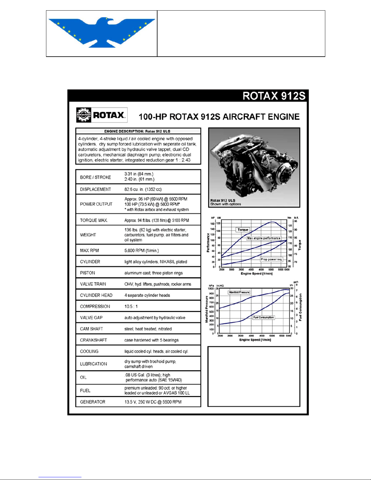
1.4 ENGINE SPECIFICATIONS
Page 14
MAINTENANCE MANUAL
STORM Century S-LSA
STORM Century S-LSA STORMAIRCRAFT
Rotax 912 S UL Aircraft Engine
(Non Certified Version)
Continuous Performance: 69.6 KW (95 HP) @ 5500 RPM
Take - off Performance: 73.6 KW (100 HP) @ 5800 RPM (Max. 5 min.)
Fuel consumption at 75% continuous power: 4.9 gph
Engine TBO (Time Between Overhaul): 1,500 hours
4-stroke, 4 cylinder horizontally opposed, dual spark ignition engine, one central camshaft,
pushrods, OHV:
• Liquid cooled cylinder heads, ram air-cooled cylinders
• Dry sump forced lubrication
• Electric starter and starter relay
• Dual breakerless, capacitor discharge ignition
• Rectifier/regulator
• Prop drive via reduction gear with integrated shock absorber.
• Integrated AC generator
• Mechanical (engine driven) fuel pump
• R.F.I. suppression
• 2 carburetors
* Full 73.6 KW (100 HP) available only when installed with Rotax tuned intake and exhaust
systems designed for the 912 S UL. Use of other intake and / or exhaust systems may result in
reduced take-off power. Potential users of the 912 S UL should consult the 912 S Maintenance
Manual attacched to this manual for more detailed information.
Page 15
MAINTENANCE MANUAL
STORM Century S-LSA
STORM Century S-LSA STORMAIRCRAFT
1.5 WEIGHT AND BALANCE INFORMATION
A – WEIGHING PROCEDURE
Following procedures are suggested for weighing operations
01 Before weighing, remove dirt, grease, humidity etc. from the aircraft.
02 The aircraft weighing shall be performed in a closed shed to avoid incorrect readings of
the scale due to wind.
03 To determine the center of gravity, the aircraft shall be set on attitude of horizontal flight.
04 All the equipment items included in the certified tare weight shall be installed IN THEIR
POSITION when performing the weighing.- These equipment items are part of the
weighing report.05 The scales must be properly calibrated, zeroed and used as per builder’s instructions. The
scales and the suitable supports for the aircraft, when needed, are normally positioned
under the aircraft wheels. Other structural points that can suitably support the aircraft may
be used, as for example the jack plates on the main spar. These points must be clearly
pointed out in the weighing report.
06 If not otherwise required by the aircraft specifications, the fuel system must be drained
until the indicator shows “ZERO” or “EMPTY” when the aircraft is on attitude of horizontal
flight. The fuel quantity remaining in the tank, in the pipes and in the engine is called
“RESIDUAL FUEL” and must be included in the tare weight.- In particular cases the
weighing can be performed with full load of fuel, provided that an accurate instrument is
available to determine the exact weight.07 If not otherwise specified in the aircraft specifications, the oil system shall be completely
drained with all the drain cocks open. In these conditions, the oil quantity remaining in the
tank, in the pipes and in the engine is called “RESIDUAL OIL” and must be included in the
tare weight. When weighing is performed with a full load of oil, the actual tare weight is
equal to the real registered weight minus the weight of the oil contained in the tank (oil
weight = oil capacity in gallons multiplied by 7,5 lbs). It must be specified in all weighing
reports whether full load of oil is included in the weights or if weights are considered after
oil drainage.
08 The brakes must not be operated when reading the scale.
09 After removing the aircraft from the scale, take note of the tare weight.
Page 16
MAINTENANCE MANUAL
STORM Century S-LSA
STORM Century S-LSA STORMAIRCRAFT
B - WEIGHING AND BALANCING CALCULATIONS
01 UNITARY WEIGHTS FOR WEIGHING AND BALANCING PURPOSES
Fuel : 6 lbs per Gal/USA = a 0,720 gr per liter
Turbine fuel : 6,7 lbs per Gal/USA = a 0,803 gr per liter
Lubricating oil : 7,5 lbs per Gal/USA = a 0,900 gr per liter
Crew and passengers : 180 lbs per person = a 81 kgs per person
02 Take the reference plane of the longitudinal distances from the C.N.. If not shown,
choose a suitable one provided that once it has been determined, it will be the only
reference for the calculation of arms and moments.
03 ALGEBRAIC SIGNS
Great care must be taken over assigning the right algebraic signs ( + o - ) during the
whole balancing calculation. For uniformity purposes, when doing these calculations, you
should always consider to observe the aircraft with its nose on the left side. In this
position, any left side arm (forward) of the reference has a minus (-) sign, and any right
side arm (rear) of the reference has a plus (+) sign. Any weight added to the aircraft on
any side of the reference HAS A PLUS (+) SIGN; any removed weight HAS A MINUS (-)
SIGN.-
When weights are multiplied by arms, the result will have a (+) sign if signs are the same,
and a (-) sign if signs are different.
Following combinations are possible:
Weights added in front of the reference plane: (+) weight x (-) arm = (-) moment
Weights added at the back of the reference plane: (+) weight x (+) arm = (+) moment
Weights removed in front of the reference plane: (-) weight x (-) arm = (+) moment
Weights removed at the back of the reference plane: (-) weight x (+) arm = (-) moment
The total weight of the aircraft is equal to the tare weight of the aircraft plus the added
weights minus the removed weights.
The total moment of the aircraft is determined by the algebraic sum of the aircraft
moment with tare weight and all the single moments of the added and/or removed items.
Page 17
MAINTENANCE MANUAL
STORM Century S-LSA
STORM Century S-LSA STORMAIRCRAFT
04
WEIGHING AND BALANCING CALCULATION FORMULAS
a Nose wheel aircraft :
Reference plane in front of the main wheels : C. G. = D - ( F x L/W )
Reference plane at the back of the main wheels : C. G. = - ( D + F x L/W )
b Nose wheel aircraft :
Reference plane in front of the main wheels: C. G. = D+R (R x L/W)
Reference plane at the back of the main wheels: C. G. = D+R (R x L/W)
c
Formulas used on AV-16 model, to be filled in, valid for nose wheel as well as for nose
wheel aircrafts. X= M/G --- % C.M.A. = X - Y/L
d WHERE : for the formulas referred to in point B-04/a and B-04/b
C.G. = distance from the reference plane to center of gravity of a/c
W = aircraft weight when weighing.
D = horizontal distance taken from reference plane to weighing point of main
wheels
L = horizontal distance taken from weighing point of main wheels to nose or tail
weighing point
R = weight on tail weighing point
e WHERE : for formulas used in point B-04/c
A = total weight when weighing
B = weights to be added if not on board when weighing.
C = weights to be deducted if on board when weighing.
G = tare weight resulting from A+B-C.
E = tare weight moment taken when weighing. (A)
F = weight moment to be added if not on board when weighing. (B)
H = weight moment to be deducted if on board when weighing.(C)
M = tare weight moment resulting from: E+F-C.
X = distance from reference plane of the gravity center of the tare weight of the
aircraft
L = length of mean aerodynamic chord
Y = distance of front end of the mean aerodynamic chord from reference plane.
% C.M.A. = tare weight gravity center position expressed in percentage of the mean
aerodynamic chord
NOTE : MAKE SURE THAT MEASUREMENT UNITS ARE EVEN
CLOSING THE OPERATIONS
Register the obtained results in the Weighing Report and Analysis.
Update all aircraft documentation (C.N. – Flight Manual - logbooks).
Page 18
MAINTENANCE MANUAL
STORM Century S-LSA
STORM Century S-LSA STORMAIRCRAFT
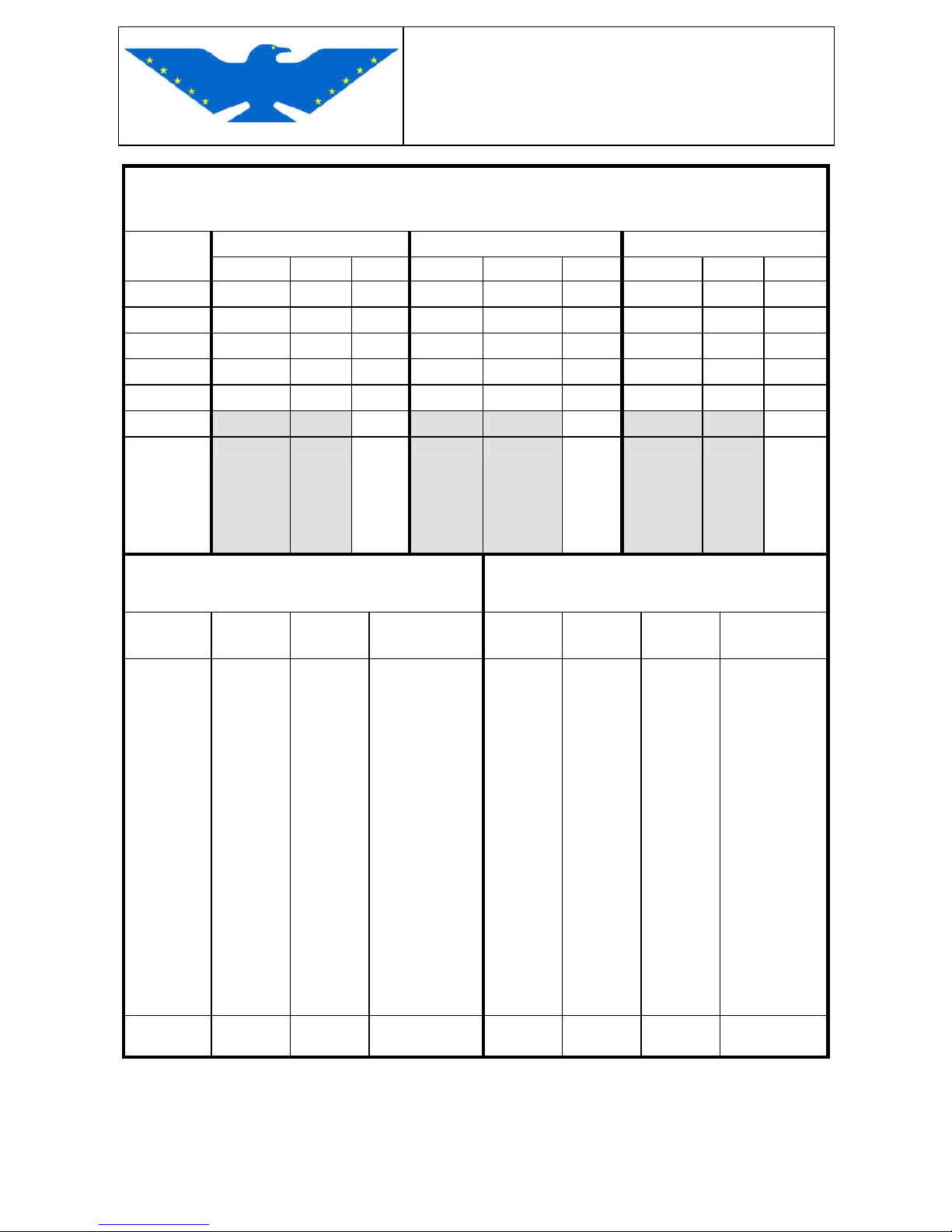
WEIGHING ANALYSIS
Support LEFT RIGHT NOSE
n° reading Reading Tare Net Reading Tare Net Reading Tare Net
1
2
3
4
5
Totals
MEAN
VALUES
(to be
registered
in the first
page)
WEIGHTS TO BE ADDED
(if not on board when weighing)
WEIGHTS TO BE DEDUCTED
(if on board when weighing)
Name Weight
Lbs
Arm
Inch
Moment
Lbs. Inch
Name Weight
Lbs
Arm
Inch
Moment
Lbs. Inch
Total Total
Page 19
MAINTENANCE MANUAL
STORM Century S-LSA
STORM Century S-LSA STORMAIRCRAFT
1.6 TIRE INFLATION PRESSURES
Nose gear tire inflation pressure: 26 psi
Main landing gear inflation pressure: 26 psi
Check tires at each refuelling to make sure there are no cuts, foreign matters, irregular wear; an
irregular wear could be due to a bad use of brakes as well as to a wrong wheel alignment.
Replace worn tires.
An excessively worn tire considerably increases the possibility and the danger of burst.
NOTE : tires shall be disposed of in compliance with current environmental provisions.
1.7 APPROVED OILS AND CAPACITY
- Type : for car use, classification API "SF" or "SG"
- Quantity : 0,7 gal max. level – 0,5 gal. minimum level, with filter total capacity 0,8 gal
- Grade over 15° C SAE 30 or SAE 40
from 0° C to 32° C SAE 40
from -18° C to 21° C SAE 40 or SAE 30
below -12° C SAE 20W/20
or use multigrade oil
from -05° C to 40° C SAE 20 W-50 SAE 20W-40
from -15° C to 40° C SAE 15 W-50 SAE 15W-40
from -25° C to 40° C SAE 10 W-40
from -25° C to 30° C SAE 10 W-30
from -30° C to 20° C SAE 5 W-20
from -30° C to 40° C SAE 5 W-50
CAUTION : check oil level at each refuelling. This check shall be done when the aircraft is as
levelled as possible. An oil level between MIN and MAX on the dipstick shall be considered
acceptable. Should the oil level drop below MIN, you shall immediately top it up with an oil
meeting ROTAX specifications.
The range between MIN and MAX signs is equal to approx. 0,13 gal oil.
Never top up oil above MAX level (maximum)
NOTE :A repeated and prolonged contact of your skin with used oil can cause dermatitis and is
carcinogenic. Avoid contact and, should it occur, wash up carefully. Keep used oil far from
children’s reach. Dispose used oil in special dumps. Empty cans shall not be thrown in domestic
use dumpsters, but disposed of in special containers.
Page 20
MAINTENANCE MANUAL
STORM Century S-LSA
STORM Century S-LSA STORMAIRCRAFT
1.8 RECOMMENDED FASTENER TORQUE VALUES
Diameter
M3 (3mm)
M4
M5
M6
M8
M10
M12
M16
M18
M20
Pitch (mm)
0.5
0.7
0.8
1
1.25
1.5
1.75
2
2.5
2.5
4.8
0.54
0.66
1.24
1.52
2.44
2.99
4.22
5.16
10.15
12.47
20.4
25.15
34.73
42.83
84.43
104.93
116.88
144.43
164.9
204.95
5.8
0.68
0.83
1.56
1.9
3.05
3.75
5.27
6.46
12.68
15.58
25.51
31.44
43.41
53.54
105.54
131.17
146.1
180.53
206.14
256.2
8.8
1.09
1.34
2.49
3.04
4.99
6.00
8.44
1043
20.3
24.94
40.81
50.31
69.45
85.66
168.8
209.8
233.7
288.8
329.8
409.9
10.9
1.53
1.88
3.5
4.28
6.87
8.43
11.86
14.53
28.54
35
57.4
70.75
97.68
120.46
237.4
295.13
328.7
406.2
463.8
576.43
12.9
1.84
2.25
4.21
5.14
8.25
10.12
14.24
17.43
34.25
42
68.88
84.9
117.21
144.5
284.9
354.1
394.5
487.4
556.56
691.7
Page 21
MAINTENANCE MANUAL
STORM Century S-LSA
STORM Century S-LSA STORMAIRCRAFT
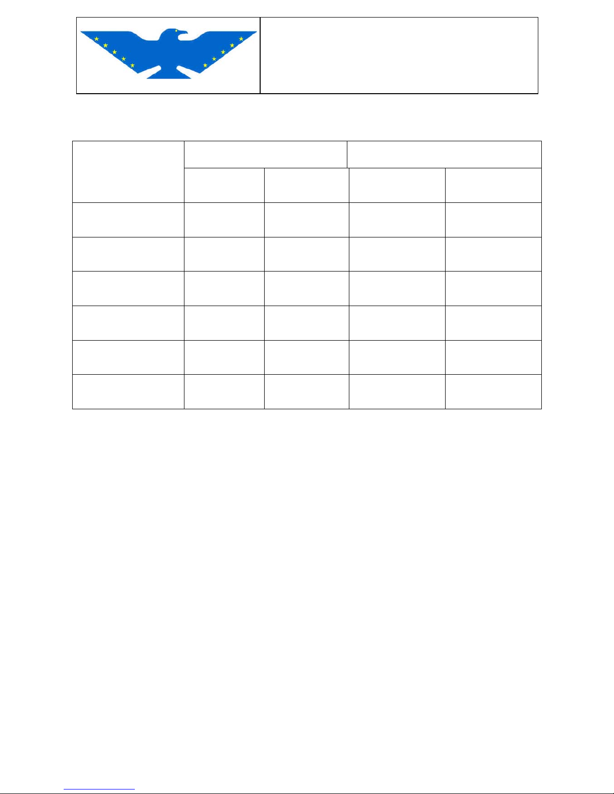
TABLE GRIP RIVETS
DIAMETER GRIP
RIVET TYPE
INCHES MILLIMETER INCHES MILLIMETER
AVEX 1661 -0410
0.1250
3.2
0.0315 ÷ 0.1695
0.8 ÷ 4.3
AVEX 1661 - 0412
0.1250
3.2
0.0469 ÷ 0.2500
1.2 ÷ 6.3
AVEX 1661 - 0414
0.1250
3.2
0.1575 ÷ 0.3750
4.0 ÷ 7.9
AVEX 1604 - 0412
0.1250
3.2
0.0938 ÷ 0.2500
2.4 ÷ 6.3
AVEX 1661 - 0512
0.1575
4.0
0.0469 ÷ 0.2500
1.2 ÷ 6.3
AVEX 1661 - 0516
0.1575
4.0
0.1575 ÷ 0.3750
4.0 ÷ 9.5
Page 22
MAINTENANCE MANUAL
STORM Century S-LSA
STORM Century S-LSA STORMAIRCRAFT
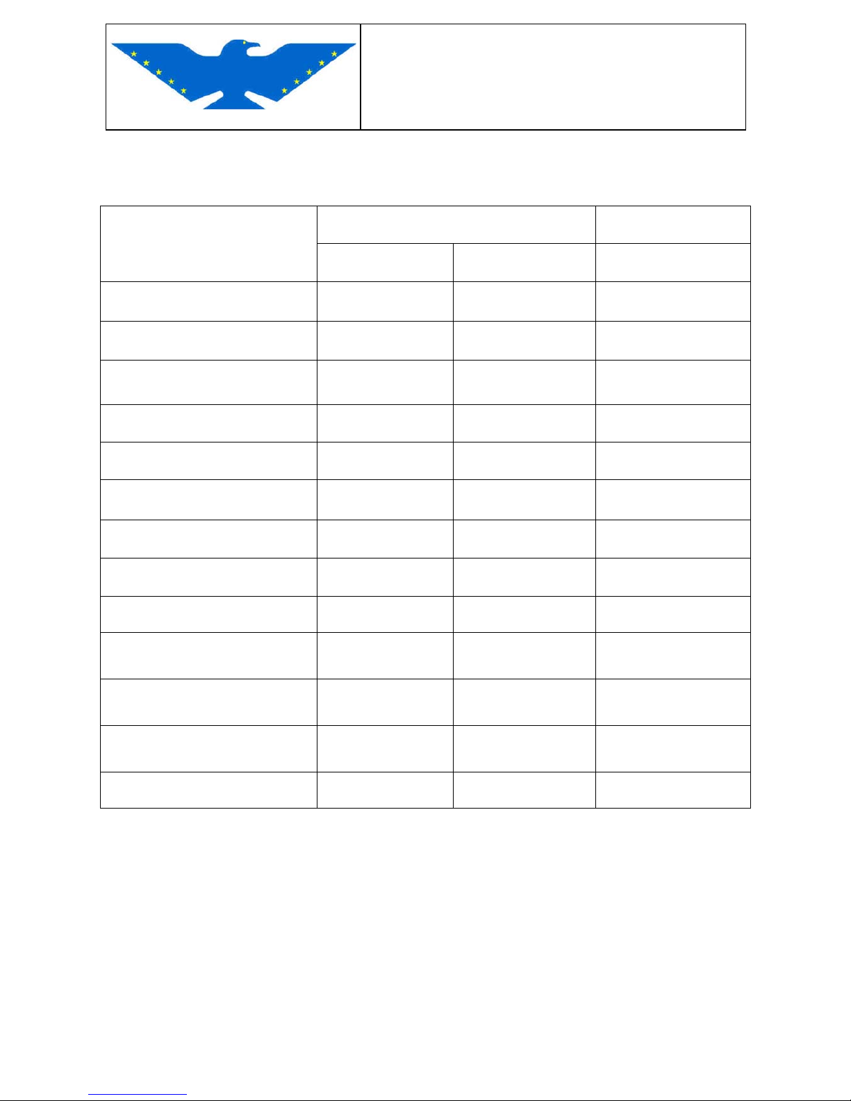
TABLE SOLID RIVETS
DIAMETER GRIP
RIVET TYPE
INCHES MILLIMETER VALUE
AN470 TO 4 – 3
1/8 x 3/16
3.2 x 4.76
L + 1 D
AN470 TO 4 - 4
1/8 x 1/4
3.2 x 6.35
L + 1 D
AN470 TO 4 – 5
1/8 x 5/16
3.2 x 7.94
L + 1 D
AN470 TO 4 – 6
1/8 x 3/8
3.2 x 9.53
L + 1 D
AN470 TO 4 – 8
1/8 x 3/4
3.2 x 12.7
L + 1 D
AN470 TO 4 – 12 1/8 x 3/4 3.2 x 19 L + 1 D
AN470 TO 5 - 6
5/32 X 3/8
4.0 x 9.53
L + 1,5 D
AN470 TO 5 - 8
5/32 X 1/2
4.0 x 12.7
L + 1,5 D
AN470 TO 5 - 9
5/32 X 9/16
4.0 x 14.29
L + 1,5 D
AN470 TO 5 - 10
5/32 X 5/8
4.0 x 15.88
L + 1,5 D
AN470 TO 5 - 12
5/32 X 3/4
4.0 x 19.05
L + 1,5 D
AN470 TO 5 - 16
5/32 X 1
4.0 x 25.40
L + 1,5 D
AN470 TO 5 - 22
5/32 X 1 3/8
4.0 x 34.92
L + 1,5 D
Page 23
MAINTENANCE MANUAL
STORM Century S-LSA
STORM Century S-LSA STORMAIRCRAFT
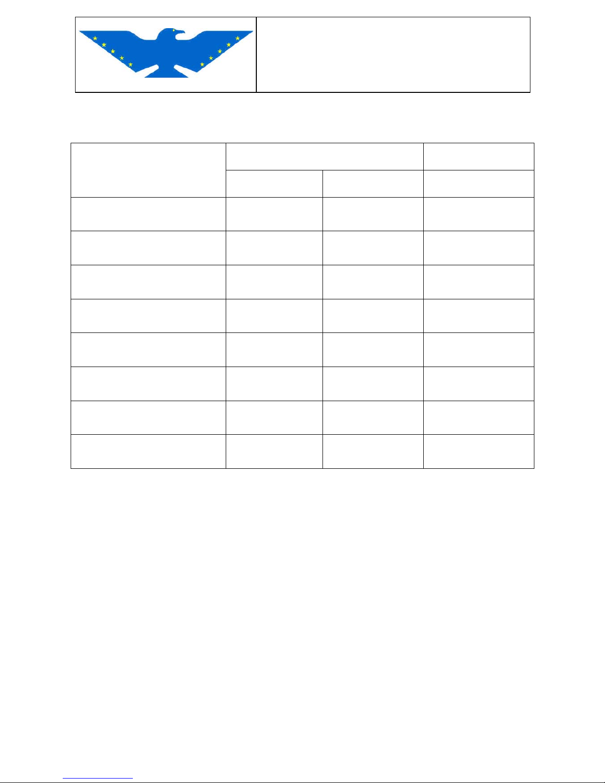
TABLE SOLID RIVETS
DIAMETER GRIP
RIVET TYPE
INCHES MILLIMETER VALUE
AN426 TO 3 - 6
3/32 x 3/8
2.38 x 9.53
L + 1 D
AN426 TO 3 - 10
3/32 x 5/8
2.38 x 15.87
L + 1 D
AN426 TO 4 - 4
1/8 x 1/4
3.2 x 6.35
L + 1 D
AN426 TO 4 – 6
1/8 x 3/8
3.2 x 9.53
L + 1 D
AN426 TO 4 – 9
1/8 x 9/16
3.2 x 14.3
L + 1 D
AN426 TO 4 – 12
1/8 x ¾
3.2 x 19.05
L + 1 D
AN426 TO 4 – 10
1/8 x 5/8
3.2 x 15.87
L + 1 D
AN426 TO 4 - 16
1/8 x 1
3.2 x 25.4
L + 1 D
Page 24
MAINTENANCE MANUAL
STORM Century S-LSA
STORM Century S-LSA STORMAIRCRAFT
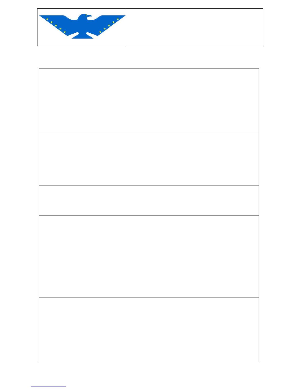
1.9 GENERAL SAFETY INFORMATION
INTRODUCTION
Some maintenance and aircraft repairing methods may involve the risk of physical injuries or
other risks for your health. This section lists some of these dangerous operations in
alphabetical order, together with the materials and the relevant equipments. The necessary
precautionary rules to avoid these risks are pointed out.
This list is obviously incomplete and all the repairs, including handling of the materials,
should be carried out keeping health and sanitary rules in mind.
Please read the safety regulations for use of the materials provided by the manufacturer or by
the supplier before using any product.
ACIDS AND ALKALIS
Caustic soda and sulphuric acid, for example, used for batteries and in cleaning products, are
irritating and corrosive for skin, eyes, nose and throat. They may cause burns. They can
destroy normal overalls. Avoid to spray such products on your skin, eyes or clothes. Wear
suitable protective gloves and glasses. Do not inhale fumes. Make sure that all necessary
products to wash your eyes, for the shower and soap are always within reach, should
accidental sprays occur.
BATTERY ACID
The gases released during battery charge are explosive. Never use flames or allow sparks to
occur near batteries in charge or just charged. Make sure that there is a suitable ventilation.
RESINS AND HARDENERS
Contact of your skin with resins and not polymerized hardeners may cause irritations,
dermatitis and intradermal absorption of toxic and harmful chemical products. Sprays may
injure your eyes. Provide for a suitable ventilation and avoid contact with your skin and eyes.
Anaerobic adhesives, cyanoacrylates, and other acrylics (superglues): many of these are
irritating, sensitizing of harmful for your skin and/or your respiratory system. Some are
irritating for your eyes, avoid contact with your skin and follow the instructions provided by the
manufacturer. The cyanoacrylate based adhesives (superglues) must never get in touch with
your skin or eyes. Should your skin or ophthalmic tissue remain tied, cover it with a clean
damp tampon and call the doctor immediately. Do not try to separate the tissue. These
product must be used in well ventilated areas because its fumes may irritate your nose and
eyes.
ISOCYNATE (POLYURETHAN) BASED ADHESIVES/DOPES
If you suffer from asthma or respiratory allergies you should not work with this kind of materials
nor work close to them, since they could cause sensitization reactions. An excessive exposure
can irritate your eyes and respiratory system. Excessive concentrations may affect your
nervous system and could even be soporific. Loss of consciousness may occur in extreme
cases. A continuous exposure to concentrations of vapors could have negative effects on your
health. An extended contact with your skin can have a degreasing effect which can irritate your
eyes and might cause dermatitis. Sprays into your eyes will cause irritations and possible
damages. Spraying should rather be executed in ventilated cabins provided with aspirator in
order to remove vapors and drops from the area. Wear gloves, glasses and faceplates.
Page 25
MAINTENANCE MANUAL
STORM Century S-LSA
STORM Century S-LSA STORMAIRCRAFT
ASBESTOS
If inhaled, asbestos may cause damages to your lungs and in some cases cancer.
Asbestos is used for brake linings. Asbestos dust to be wasted should first be dampened, then
put into a sealed container with a special label to be sure that it will be wasted in a safe way.
Should you need to cut or to drill materials containing asbestos, wet the part and use only slow
speed hand or electrical tools. The present law does not allow to use asbestos.
ANTIFREEZE
See also: isopropyl alcohol, glycol, methanol, solvents.
Highly flammable, flammable, combustible.
It is used in the cooling system of the cylinder heads. If heated, the antifreeze (glycol) can
release detrimental vapors. Avoid to inhale them. Antifreeze can be absorbed in injurious and
toxic quantities through your skin. If ingested, it could be lethal and a doctor should be contacted
immediately.
COMPRESSED AIR EQUIPMENTS
Never point a high pressure nozzle at your skin, since the liquid could pierce your skin and
cause hard injuries.
GENERAL SHOP TOOLS AND EQUIPMENTS
It is fundamental that tools and equipments be kept in good conditions and that, if necessary,
the proper safety equipments be used.
Never use tools or equipments for purposes other than their specific use.
Never overload equipments like hoists, jacks, trestles or slings.
The damage caused by overload is often not immediately perceivable and it might cause fatal
damages next time you use it.
Do not use damaged or defective tools, specially high speed equipments as grinding wheel. A
grinding wheel can break without notice causing hard injuries. Wear suitable protective glasses
when using grinding tools.
GAS CYLINDERS
Take care while using gases, like oxygen, acetylene, etc. to avoid leaks from the cylinders or
from the piping and avoid lighting sources.
FUEL
Try as far as possible not to get your skin in touch with fuel. Should it occur, wash the affected
part with water and soap.
GASOLINE
Highly flammable. Observe the signs “no smoking” .- The ingestion might cause irritations of
your mouth and throat and the absorption in your stomach could cause you a torpor condition
and loss of consciousness. Transit of liquids through your lungs, for example when vomiting,
is a serious risk. Gasoline dehydrates the skin and may cause irritations and dermatitis if the
contact is prolonged and repeated. Gasoline can irritate your eyes. It can contain remarkable
q
uantities of benzol, which is toxic if inhaled, and the concentration of gasoline vapors must
Page 26
MAINTENANCE MANUAL
STORM Century S-LSA
STORM Century S-LSA STORMAIRCRAFT
be kept very low. High concentrations will irritate your eyes, nose and throat and cause
nausea, headache, depression and symptoms of drunkenness. Very high concentrations will
cause a quick loss of consciousness.
While using gasoline, make sure that there is always a suitable ventilation.
Should there be a high vapor concentration raised from pouring it in a limited space, avoid as
far as possible the serious consequences of inhalation. Gasoline shall not be used as a
cleaning solution. Avoid to do transfer operations with your mouth.
OVERHUNG LOADS
Danger must always be taken into consideration when a load is lifted and hung. Never work
under loads which are hung or lifted without any support. Make sure that the lifting units like
jacks, hoists, slings, etc. are suitable for the specific work and conditions and that they are
regularly overhauled.
INSULATING FIBERS
These are used for soundproofing. The fibrous nature of the surfaces and the sharp edges
may cause skin irritations. The effect is normally physical and not chemical. The necessary
precautions shall be taken to avoid the prolonged contact with your skin, taking up suitable
working methods and wearing protective gloves.
BRAKE FLUID
Highly corrosive, avoid contact with painted parts. If the brake liquid is erroneously poured on
painted parts, immediately wash with cold water.
Sprays on skin and eyes are irritating. Avoid as much as possible contact with your eyes and
skin.
Page 27
MAINTENANCE MANUAL
STORM Century S-LSA
STORM Century S-LSA STORMAIRCRAFT
1.10 NOTIFICATION OF SAFETY OF FLIGHT CONCERNS
To notice the manufacturer about safety of flight concerns during maintenance or repair
operations, please fill the form below and send by fax at +390773511407 or by mail at:
STORMAIRCRAFT
Via Enzo Ferrari
04016 Sabaudia (LT)
ITALY
tel +390773515216
www.stormaircraft.com
NOTIFICATION
MAKE MODEL SERIAL NUMBER DATE OF MFG
COMMENTS (list applicable part number) NOTE
DATE OF INSPECTION
Signature
Page 28
MAINTENANCE MANUAL
STORM Century S-LSA
STORM Century S-LSA STORMAIRCRAFT
CHAPTER 2
INSPECTION AND MAINTENANCE PERIODS
PERIOD DESCRIPTION
This chapter includes all the inspection and maintenance procedures needed for STORM Aircraft.
The operative life of STORM Century S-LSA, as determined in the project, is 10000 flight hours.
Regular inspections shall be carried out when reaching respectively : 50 , 100, 200 , 600 ,1000
and 1200 flight hours.
Moreover, after the first 25 hours , when the aircraft is new, the 100 hours inspection must also be
done on the engine, as specified in ROTAX 912 UL S engine manual, and a visual check shall
be made on all screws coupling the structural parts.
The period between the two 200 hours inspections must not exceed one year.
For each inspected item, the person in charge for the aircraft maintenance shall sign the check list.
The completion of the inspection must be entered in a special register.
The results and the corrections must be registered in a special report and filed with the inspection
list in the maintenance register of the aircraft.
NOTE : maintenance may be done in advance, but for no reason should it be postponed.Maintenance can only be postponed upon agreement with the aircraft airworthiness check
Authority, upon engine and fittings builder’s specifications or on aircraft designer’s directions.
Page 29

MAINTENANCE MANUAL
STORM Century S-LSA
STORM Century S-LSA STORMAIRCRAFT
USE OF THE INSPECTION LIST
In the following lists all checks marked with the symbol 4
must be performed on the aircraft on specified periods.-
When a special 200, 600, 1000, 1200 hours or a planned annual inspection is
performed, the 100 hours inspection must be carried out as well.
NOTICE:
If an inspection or maintenance must be carried out with connected battery and ignition,
make sure first that the area
around the propeller is free.
---------------------------------------------------------------------------------
When inspections must be carried out with the engine on, make sure that there are
extinguishers within reach and that the aircraft is braked and blocked with chocks.-
IMPORTANT :
As far as ROTAX 912 engine installation, inspections and maintenance are concerned,
carefully follow the instructions of the engine manual supplied with the engine.
----------------------------------------------------------------------------------------
For maintenance and inspections of parts with finished materials or supplied by other
manufacturers, such as: propeller, hubs, wheels, brakes, pumps, filters, pulleys, cables,
pipes, bolts, rivets, extrusions, fusions, etc., follow the suggestions of the manufacturer, if
supplied.
Page 30
MAINTENANCE MANUAL
STORM Century S-LSA
STORM Century S-LSA STORMAIRCRAFT
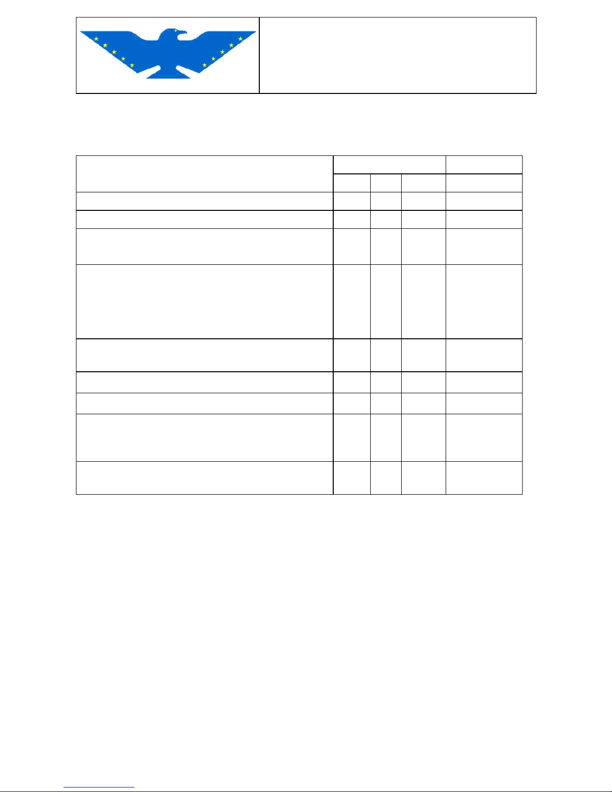
2.1 POWER CHECK
Inspection description Flight hours performed by
50 100 special
Clean the aircraft before each inspection
4 4
I. PERFORM POWER CHECK
1 - Let the engine run until it reaches oil temperature
of 50° C – check and verify engine instruments
4
4
OWNER
2 - Check of the ignition circuit (RPM= 3850)
Power loss of circuit A (RPM = 300 max)
Power loss of circuit B (RPM = 300 max)
Difference between circuits A-B (RPM = 115
max)
4 4
OWNER
3 - Warm air to carburetor, if installed
Check power loss (NOT FORESEEN)
OWNER
4 - Check the ignition switch
4 4
OWNER
5 - Check fuel selector ON / OFF
4 4
OWNER
6 - Ignition OFF - Battery OFF
Fuel selector OFF
Remove ignition lock key
4 4
OWNER
7 - Disconnect battery-
Open all the inspection doors
4 4
OWNER
Page 31
MAINTENANCE MANUAL
STORM Century S-LSA
STORM Century S-LSA STORMAIRCRAFT
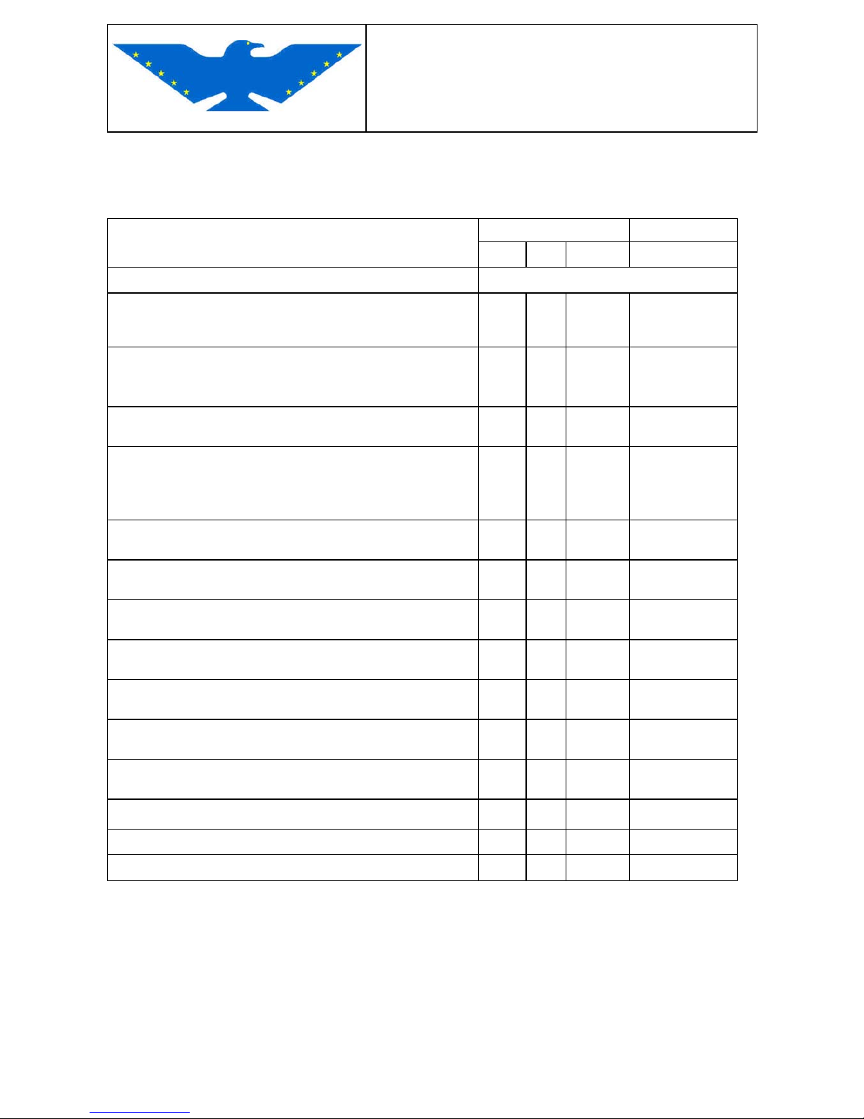
2.2 ENGINE COMPARTMENT
Inspection description Flight hours performed by
50 100
special
II. ENGINE COMPARTMENT
1 -
Remove cowling, inspect for cracks, burnings,
distortions, missing screws in the fastening
system. – Remove dirt from cowling .-
4 4
OWN
2 - Check if there are fuel, oil or coolant leaks in the
engine compartment
Clean engine compartment.-
4 4
A&P
3 - Check carburetor – verify overflows and their
discharge position – check pipes
4 4
A&P
4 - Visual check of the engine anchoring to the motor
cradle – check possible cracks or distortions of
motor cradle – visual check of the silent blocks of
the motor cradle
4 4
A&P
5 - Visual check: exhaust manifolds – muffler exhaust
pipes – check cracks or leaks on heat exchanger
4 4
A&P
6 - Visual check of carburetor – air filters – fuel pipes
fastenings
4 4
OWN
7 - Visual check : lubrication circuit tank - oil cooler -
oil cooler fastenings – possible leaks on oil pipes
4 4
OWN
8 - Visual check : cooling circuit tank – coolant tank
– possible leaks on pipes
4 4
OWN
9 - Visual check of fuel pipes, check if safe and if
there are leaks
4 4
OWN
10- Fuel filter check – check if safe and if there are
leaks
4 4
OWN
11- Visual check: inspect for possible cracks or leaks
on electric fuel pump - testing
4 4
OWN
12- Visual check : check battery and cables
4 4
OWN
13- Visual check: vacuum pump - pipes
4 4
A&P
14- Replace vacuum system filter
4 4
500
A&P
Page 32
MAINTENANCE MANUAL
STORM Century S-LSA
STORM Century S-LSA STORMAIRCRAFT
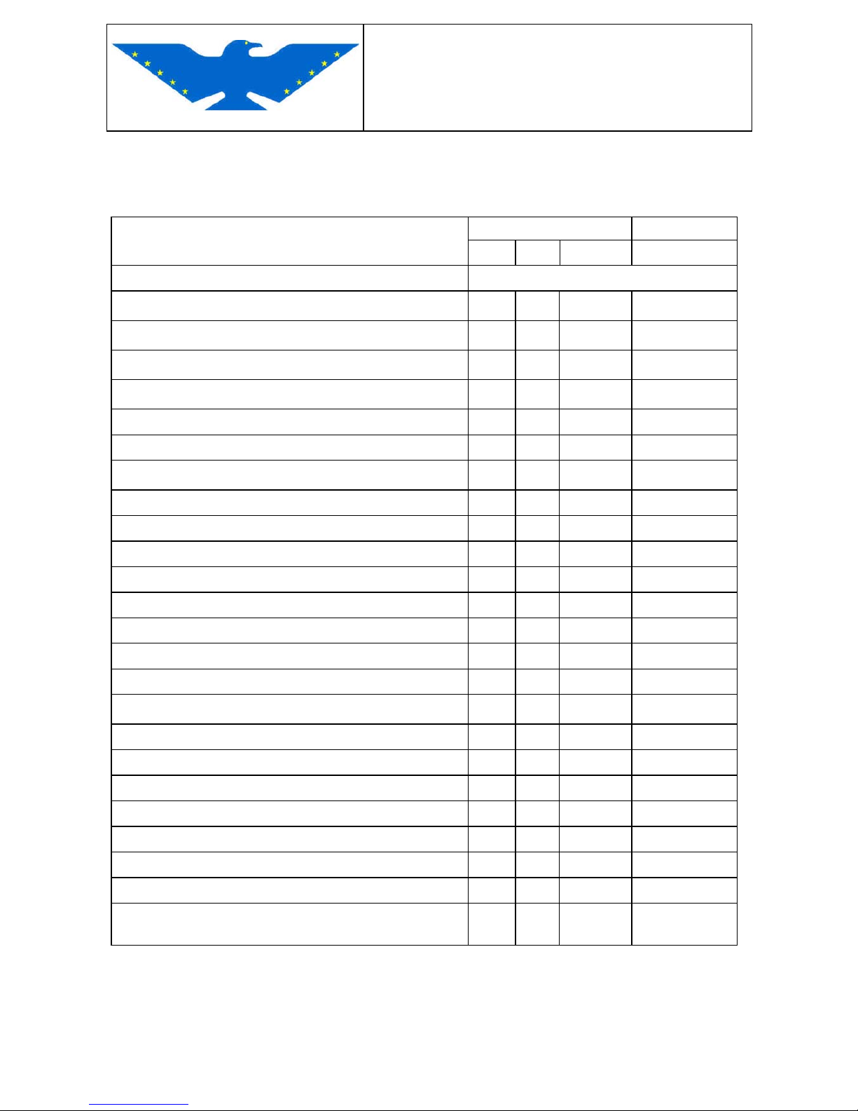
2.3 ENGINE
Inspection description flight hours performed by
50 100
special
III. ENGINE - (see Rotax 912 engine manual)
1 - Engine cleaning
4 4
200
OWN
2 - Visual check of engine
4 4
200
OWN
3 - Check of possible leaks
4 4
200
OWN
4 - Check of engine silent-block supports
4 4
200
OWN
5 - Check of engine external parts
4 4
200
A&P
6 - Visual check of reduction gear
4 4
200
A&P
7 - Oil level check
4 4
200
OWN
8 - Engine oil change
4 4
200
A&P
9 - Oil filter change
4 4
200
A&P
10- Check of cooling system
4 4
200
A&P
11- Inside washing of cooling system 200
A&P
12- Change of coolant (every 2 years or) 200
A&P
13- Change the cooling system pressure cap 200
A&P
14- Visual check and regulation of carburetors
4 4
200
A&P
15- Visual check and regulation of carburetors
4
200
A&P
16- Control cables check
4 4
200
OWN
17- Check of spark plug wires
200
A&P
18- Change of spark plugs
200
A&P
19- Check of spark plug wires
200
A&P
20- Compression check
200
A&P
21- Check of engine electric parts
4 4
200
A&P
22- Change of rubber parts
5 years
A&P
23- Check of overvoltage relay
200
A&P
24- Total engine overhaul
1200
15
years
A&P
Page 33
MAINTENANCE MANUAL
STORM Century S-LSA
STORM Century S-LSA STORMAIRCRAFT
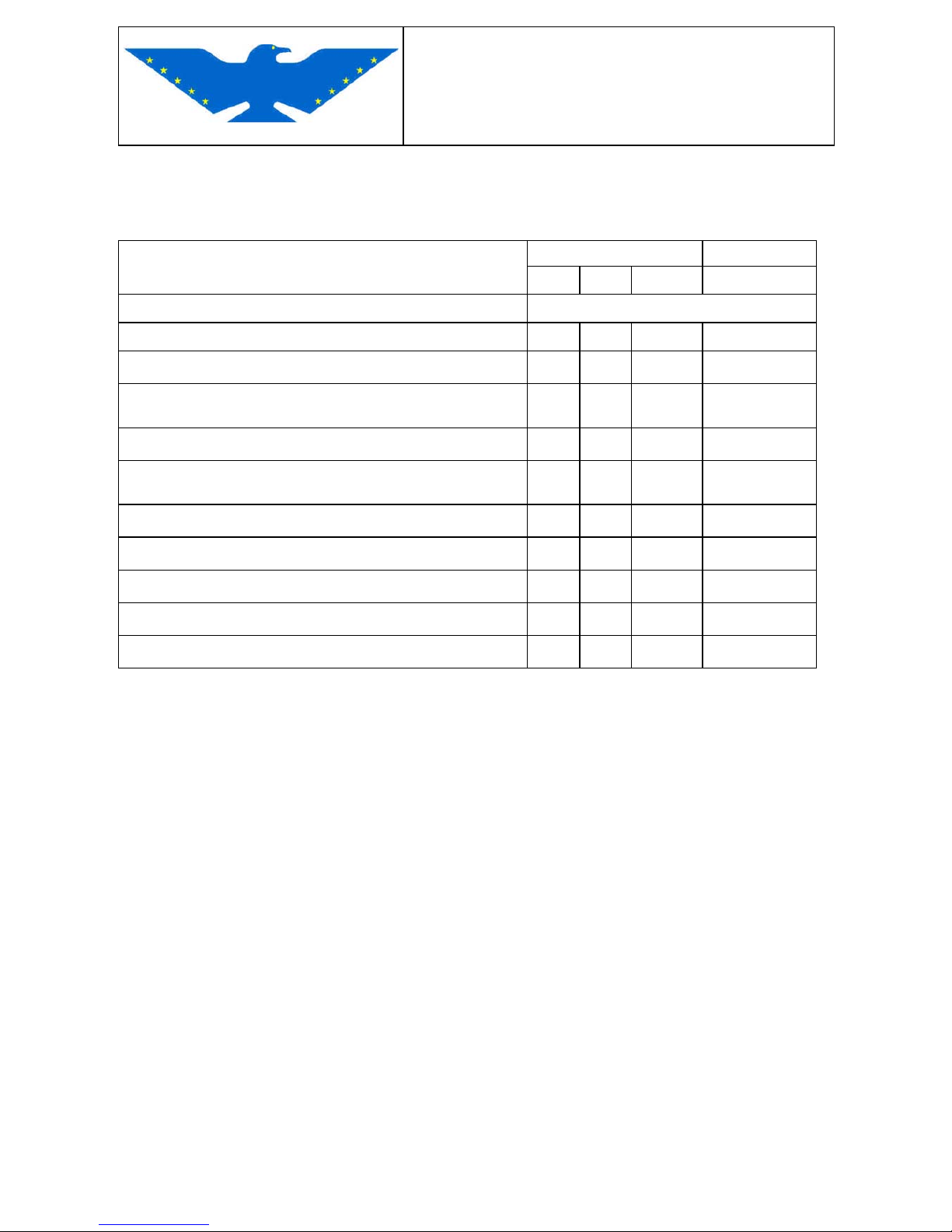
2.4 PROPELLER
Inspection description flight hours performed by
50 100
special
IV. PROPELLER
1 -
Remove spinner
4 4
A&P
2 - Check possible breaking or cracks of the spinner
4 4
OWN
3 - Make sure that propeller blades and surfaces are
intact
4 4
OWN
4 - Check inclination and trailing edge of blades
4 4
OWN
5 - Check the perfect torque of bolts (do not release
them)
4 4
OWN
6 - Make sure there are no cracks near the hub
annual
OWN
7 - Change graphite brushes of pitch
4
OWN
8 - Make sure the electric parts are intact
4 4
OWN
9 - Make sure the moving parts are intact
4 4
OWN
10- Clean and install the spinner
OWN
Page 34
MAINTENANCE MANUAL
STORM Century S-LSA
STORM Century S-LSA STORMAIRCRAFT
2.5 COCKPIT
Inspection description flight hours
performed by
50 100
special
V. COCKPIT
1 - Inspect canopy for faults or cracks
4
OWN
2 - Check locking device of canopy
4
OWN
3 - Check safety belts and anchoring
4
OWN
4 - Remove seats – remove dirt
4
OWN
5 - Check flap control lever – check its smooth running
4
OWN
6 - Check flap lever connections
4
OWN
7 - Check trim and deflector excursion and efficiency
4
OWN
8 - Check smooth running of control movements
4
OWN
9 - Check conditions of rubber wirings
4
OWN
10- Check if antiskid material on pedals is well fixed and
make sure that there is nothing interfering - check free
pedal movement, its regulation and max. range –
lubricate if necessary
4
OWN
11- Check and adjust the mechanical cable braking system
on passenger’s side – inspect for possible damages
4
OWN
12- Check brake pumps on left side, inspect for possible
damages or leaks
4
OWN
13- Check for leaks or damages of parking brakes
4
OWN
14- Check free movement of the two control sticks
4
OWN
15- Keeping control stick blocked, check aileron and
stabilizer clearance
4
OWN
16- Check if markings of instrument limits are intact
4
OWN
17- Check tags and their exact position
4
OWN
18- Remove instrument panel – inspect components,
switches, fuses, instruments, wires and pipes for
possible connection faults – remove dirt
200
A&P
Page 35
MAINTENANCE MANUAL
STORM Century S-LSA
STORM Century S-LSA STORMAIRCRAFT
Inspection description
flight hours performed by
50 100 special
VI. COCKPIT
19- Check main wing connection
4
OWN
20- Make sure that the fuel selector has no clearance
4
OWN
21- Inspect for possible leaks from fuel cock
4
OWN
22- Clean fuel tank and fuel trap 600
5years
OWN
23- Check tank vents and cap
4
OWN
24- Replace fuel pipes
600
5years
A&P
Page 36
MAINTENANCE MANUAL
STORM Century S-LSA
STORM Century S-LSA STORMAIRCRAFT
2.6 SURFACE AND STRUCTURE CHECKS
Inspection description flight hours performed by
50 100 special
VII.
SURFACE AND STRUCTURE CHECKS
01 - Check wing surfaces, control surfaces, fuselage;
inspect for paint cracks around the rivets which could
detect hidden cracks
4
OWN
02 - Make sure that aileron clearance is not excessive
4 4
OWN
03 - Check for possible damages and/or imperfections on
aileron connections and wing controls
4
OWN
04 - Make sure there are no anomalies of the flap
actuators on wings and fuselage – make sure there
are no excessive clearances
4
OWN
05 - Check and, if necessary, remove stabilator, inspect for
corrosion, check bolts, lubricate and, if removed,
reinstall the stabilator
1000
OWN
06 - Check stabilator connections, trim winglet and if the
trim winglet excursion is normal, inspect for corrosion
signs, check control rod of stabilator – lubricate
4
OWN
07 - Check if the electrical system earthing is suitable
4
OWN
08 - Inspect for possible corrosion areas between stainless
steel firewall and airframe
4
OWN
09 - Check fastening of the radio and transponder
antennas; check wirings and possible corrosion signs
4
OWN
10 Check fastening of Pitot tube and statics
4
OWN
11 - Check fuel bleeding system in the fuselage, inspect
for possible faults of the return spring
4
OWN
12 - Make sure that all the external tags are intact and in
place
4
OWN
Page 37
MAINTENANCE MANUAL
STORM Century S-LSA
STORM Century S-LSA STORMAIRCRAFT
2.7 LANDING GEAR
Inspection description flight hours performed by
50 100 special
VIII. LANDING GEAR
01 - Check possible leaks of hydraulic braking system and
pipes
4
OWN
02 - Change braking oil and pipes 1000
OWN
03 - Check mechanic parts of braking system
4
OWN
04 - Visual check of main gear struts
Visual check of leaf spring and nose wheel
4
OWN
05 - Visual check of bolts coupling landing gear and
airframe
4
OWN
06 - Remove main and nose gear struts and inspect for
possible distortions; check airframe – replace bolts
and reassemble – do a geometric and functional
check
1200
A&P
07 - Remove fairing of main gear wheels and check
possible anomalies or wear – check brake disc and
lining
4
A&P
08 - Disassemble the wheel assembly, clean and lubricate
bearings, if necessary replace brake linings and discs
if not already replaced before due to wear
1000
A&P
Page 38
MAINTENANCE MANUAL
STORM Century S-LSA
STORM Century S-LSA STORMAIRCRAFT
2.8 FUSELAGE – AIRFRAME – COCKPIT INSPECTION
CONTENTS OF THE SCHEDULED ANNUAL INSPECTION
01 Before inspection, remove or open all necessary inspection ports or access doors,
fairings and covers. Carefully clean the aircraft.-
A. FUSELAGE AND AIRFRAME INSPECTION
01 Structure and coating – check possible deterioration, distortion or any other crack and
possible faulty fastening of accessories
02 Component systems - check if correctly installed, if there are apparent faults or
defective operation
03 Check conditions of tanks and connected parts
B. COCKPIT INSPECTION
01 General check of possible dirt or foreign matters which may alter the operation of
controls
02 Seats and safety belts – check conditions and apparent faults
03 Windows and windshields – inspect for deterioration or cracks
04 Instruments – check installation conditions, markings and (wherever possible) defective
operation
05 Flight and engine controls – check correct installation and possible defective operation
06 Battery – check if installation and charge are correct
07 Magnetic compass – check if intact and if correctly operating (compensation validity not
over 48 months for VFR)
08 Check the correct installation, the general conditions, possible apparent faults or unsafe
fastenings of all systems.
Page 39
MAINTENANCE MANUAL
STORM Century S-LSA
STORM Century S-LSA STORMAIRCRAFT
2.9 ENGINE – NACELLE – LANDING GEAR INSPECTION
C. ENGINE PARTS AND NACELLE INSPECTION
01 Engine unit - check if there are evident oil, fuel and hydraulic fluid leaks and determine
the reasons for such leaks
02 Stud bolts and nuts – check if driving torque correct and inspect for possible loosening
03 Inside part of the engine – check cylinder compression and make sure that there are no
metallic particles or foreign matters on filters and on the fuel trap caps (if compression is
low, make sure that the inside conditions are normal and that the inside tolerances are
correct)
04 Engine fastenings – inspect for possible cracks and for missing fastenings; check
support loosening
05 Elastic vibration dampers – check if in bad conditions or damaged
06 Engine controls – check possible faults, if the stroke is correct (unsuitable regulation)
and if brakings are correct.
07 Hoses – pipes and clamps – check possible leaks, deterioration and loosening
08 Exhaust pipes – check possible cracks, faults and wrong fastening
09 Accessories – check if there are evident assembly faults.
10 All systems – check correct installation, verify general conditions and make sure there
are no faults and unsafe fastenings
11 Cowlings – check if there are cracks and faults
D
LANDING GEAR INSPECTION
01 Check conditions and safe fastening of all components
02 Hydraulic lines – inspect for possible leaks
03 Wheels – check if there are cracks or faults, check bearing conditions
04 Tires – check if worn, cut or abraded.
Page 40
MAINTENANCE MANUAL
STORM Century S-LSA
STORM Century S-LSA STORMAIRCRAFT
2.10 WING – STABILIZER – PROPELLER – RADIO SET INSPECTION
E. WINGS
01 Inspect (where applicable) all wing parts, all its movable parts, the relevant controls and
the central section assembly and check general conditions, the possible deterioration of
structure or covering, the safe fastening, the correct installation and the correct
operation of the components.
F. STABILIZER
01 Inspect (where applicable) all parts and systems making up the whole stabilizer
assembly, check movable surfaces and relevant controls, check general conditions,
possible deterioration of structure or covering, check safe fastening, correct installation
and correct operation of components.
G. PROPELLER INSPECTION
01 Propeller assembly – inspect for cracks, notches, chippings and oil leaks from reduction
gear
02 Bolts – check correct driving torque and loosening of locks
03 Control gears – check correct operation, safe fastening and stroke limitations.
04 Electrical system of propeller – check correct operation and safe fastening
H. RADIO SET INSPECTION
01 Radio and electronic equipments – check correct installation and safe fastening
02 Cables and cable ducts – check if path is correct, if fastening is safe and if there are
evident faults
03 Connections and shielding – check correct installation and conditions
04 Antennas – check conditions, safe fastening and correct operation
Page 41
MAINTENANCE MANUAL
STORM Century S-LSA
STORM Century S-LSA STORMAIRCRAFT
2.11 AIRWORTHINESS PRESCRIPTIONS AND POWER CHECK
I. AIRWORTHINESS PRESCRIPTIONS
01 Verify the application of the airworthiness prescriptions concerning the aircraft and the
relevant parts and pertinences.
02 Check aircraft configuration for possible changes and verify the approval status.
03 Check presence and conditions of all tags, compulsory markings and foreseen service
notices and restore if lacking or missing
04 Verify validity of the weighing and balancing data in connection with changes of
configuration and/or scheduled deadlines.
05 Verify time limits of parts having a limited use or life.
J. AT THE END OF THE INSPECTION
01 At the end of the inspection and before restarting the aircraft operation, do following
power checks to verify if the performance is meeting the manufacturer’s
recommendations.
K. POWER CHECK (see installed engine manual)
01 Delivered power at fix point : RPM P.A.
02 Idling rev. control : RPM P.A.
03 Ignition check A + B : RPM
3850 RPM - max .drop 300 RPM : circuit A: ______
max diff. between circuit A and B 115 RPM : circuit B: ______
04 Fuel pressure :
0,15 - 04 bar (2,2 - 5,8 p.s.i.)
05 Lubricant pressure at max RPM :
06 Cylinder heads temperature :
Cylinder heads temperature :
07 Lubricant temperature :
Page 42
MAINTENANCE MANUAL
STORM Century S-LSA
STORM Century S-LSA STORMAIRCRAFT
2.12 SYSTEM AND AVIONICS MAINTENANCE
SYSTEM AND AVIONICS MAINTENANCE
The attached table is a reference guide for the development of a maintenance schedule for all
systems and avionics installed on the aircraft.The terms used in the table will have the following meaning:
OPERATIONAL TEST: quantitative check to make sure that a system, a system function or
equipment is working as expected.- It is mainly used to search failures or malfunctions.- No
equipments nor instruments other than the ones supplied with the aircraft are needed for this kind
of check.-
FUNCTIONAL TEST: quantitative check to make sure that a system, a system function or
equipment is working within the limits and the tolerances as defined in the applicable test
specifications.- This kind of check normally requires functional testing equipments (usually test
benches) and the recording of the taken measurements.-
BENCH TEST: this test points out the operational mode of check rather than its content.- It is
used for the quantitative check (functional check) of the operation parameters of the instruments
taken off the aircraft.
The laboratory instruments, the builder’s procedures and data or approved international standards
shall be applied for the bench test of the aircraft on trial.
VHF unit Functional Test 24 months
Pitot system – Statics Static system inspection 48 months
Altimeter Functional Test 48 months
Magnetic compass Operational Test 48 months
ATC Transponder Functional Test 24 months
Page 43
MAINTENANCE MANUAL
STORM Century S-LSA
STORM Century S-LSA STORMAIRCRAFT
2.13 FUNCTIONAL TEST (1)
ACCEPTANCE FLIGHT LIST AFTER OVERHAULS STORM Century S-LSA
Inspection type :...................................... Pilot : ......................................
Date :...................................... Take-off : ......................................
Airport :...................................... Landing : ......................................
FUNCTIONAL TEST CHECKED
NO YES
Displayed fuel quantity
Altimeter on QNH
Radio sets check
Check of basic navigation instruments
Electric fuel pump
Cold engine start operation
Oil pressure gauge
Voltmeter
Engine revolution counter RPM
Cylinder temperature CHT
Parking brake
Flaps
A and B ignition circuits check
Operation during take-off
Speed indicator
Rate-of-climb indicator (option)
Compass
Operation during climb
Cylinder temperature CHT
Oil temperature
Page 44
MAINTENANCE MANUAL
STORM Century S-LSA
STORM Century S-LSA STORMAIRCRAFT
FUNCTIONAL TEST (2)
FUNCTIONAL TEST CHECKED
NO YES
Cockpit heating, if connected
Operation at max. cruising speed
Trim range on Stabilator
Operation at minimum speed
Stall
Landing functionality
On ground, shut down functionality
On ground, warm engine ignition functionality
NOTES:
----------------------------------------------------- (Pilot)
Page 45
MAINTENANCE MANUAL
STORM Century S-LSA
STORM Century S-LSA STORMAIRCRAFT
2.14 DAILY INSPECTION
Date Performed by:
COCKPIT
01. switch OFF
02. battery ON
03. fuel remote level indicator check
04. flaps out
05. trim on zero – free controls
06. battery OFF
EXTERNAL CHECKS
01. canopy integrity check
02. bleedings: check fuel tank and filter (before moving the aircraft)
03. fuselage : check lower and upper side integrity – radio antenna - transponder antenna
04. fin and rudder : check integrity and free movements
05. Stabilator and tab - connections : check integrity and free movements
06. nose wheel unit : check tire - integrity
07. main landing gear : check tires – if pressure as required - brakes
08. flap – right aileron : check integrity and free movement
09. right wing leading edge – make sure there are no dents
10. check if Pitot tube and statics are free
2. DAILY INSPECTION
Date Performed by:
ENGINE COMPARTMENT
01. remove upper cowling
02. engine compartment free from foreign matters
03. no liquid leaks
04. check the unfixed or unbraked parts
05. check oil level
06. check cylinder head coolant level
07. reassemble and fasten upper cowling
PROPELLER
01. spinner and propeller : check fastening and integrity
02. make sure the propeller blades have no notches nor scratches
EXTERNAL CHECKS, CONTINUED
01. check if landing light fastened and intact
02. engine cowling unit intakes: check if obstructed, clear if necessary
03. left wing leading edge: make sure there are no dents
04. aileron and flap : check integrity and free movement
Page 46
MAINTENANCE MANUAL
STORM Century S-LSA
STORM Century S-LSA STORMAIRCRAFT
CHAPTER 3
STRUCTURES
3.1 DESCRIPTION OF FLIGHT CONTROLS
The main, traditional flight controls used by the pilot for the immediate control of rolling, yaw and
pitching consist of:
Aileron - control
Rudder - control
Stabilator - control
Attitude control, Stabilator Trim
The flight controls are provided with stops to limit the travel of every aerodynamic surface
controlled by the system.
The flight controls can be operated from the pilot seats, both equipped with control stick for
aileron/Stabilators operation and with rudder pedals to operate the rudder.
1- Aileron control
The aileron control drive, which is connected to the control stick, is a rigid rod with connecting
rods mounted on double ball bearings.
2- Rudder, fin control surface
The fin control surface is controlled through the pedals, and the control is transmitted from
pedals to fin control surface through cables.
3- Stabilator control
The Stabilator control is a rigid rod working on bearings and is operated through the control
stick in the cockpit.
4- Stabilator Trim
Two pull-up/push-down buttons on both control sticks operate an electric actuator positioned
on the rear part of fuselage, which transmits the movement to the Stabilator trim through a
transmission bar. The transmission from le actuator works through a bar connected to the
hinge bracket of the Stabilator trim (see aircraft structure chapter).
The position of the trim device as to the setting range is displayed by an indicator on the lower
part of the instrument panel.
Page 47
MAINTENANCE MANUAL
STORM Century S-LSA
STORM Century S-LSA STORMAIRCRAFT
3.1.1 FLIGHT CONTROL INSPECTION
Open all inspection doors of the aircraft in order to carry out inspections and maintenance.
For flight control removal and installation, please refer to drawings in the aircraft structure chapter,
in the specific pages.
Check every 100 hours if control stops are intact, inspect for wear, loosening or loss of
adjustment.
Check every 100 hours if controls are easily operating, if they are smoothly running, free from
jamming, excessive friction or excessive elastic deformation.
FOLLOWING TOLERANCES ARE ACCEPTED FOR CONTROL SURFACES AND TRIM
downwards upwards
Aileron
12° ± 2° 15° ± 2°
Rudder
25° ± 2° RH 25° ± 2° LH
Stabilator
20° ± 2° 32° ± 2°
Stabilator Trim
20° ± 2° 20° ± 2°
Movement and effect of aerodynamic controls in the cockpit
Aileron to right (clockwise) to lower the right wing
Stabilator backwards to pitch
Rudder right pedal forward for heading right
Trim the hand movement on the switch shall be in the same
direction as the aircraft response (forward/nose down)
(backwards/nose up)
Page 48
MAINTENANCE MANUAL
STORM Century S-LSA
STORM Century S-LSA STORMAIRCRAFT
3.1.2 FLAP CONTROL
An electric actuator installed inside the central console (for checking remove the central cover)
controls the flaps on four positions: 0° - 10° - 20° - 35°.
The flaps are moved by two rigid rod between the wing and the fuselage. The pilot may select the
suitable flap position with the switch installed in the center console. The position indicator is
installed in the upper right side of the instrument panel. For further details, refer to aircraft structure
chapter, flaps control.
Optionable : Electric Flap Controller (EFC) - Automatic / Manual Flap control system installed in
the central console.
Check every 100 hours if the control is working smoothly and safe, free from any jamming,
excessive friction and excessive elastic deformation, and that the slots are intact.
For removal and installation, please refer to the aircraft structure chapter, flap control.
ACCEPTED TOLERANCES IN VARIOUS FLAP CONFIGURATIONS
Flaps 0° Tolerance
Flaps 10° Tolerance ± 2°
Flaps 20° Tolerance ± 2°
Flaps 35° Tolerance ± 2°
Movement and effect of flap control in the cockpit
Flaps control - forward to retract the flap system
- backwards to extract the flap system
Page 49
MAINTENANCE MANUAL
STORM Century S-LSA
STORM Century S-LSA STORMAIRCRAFT
3.2 REMOVAL - INSTALLATION
3.2.1 WING (A&P)
REMOVAL
Disconnect battery.
Empty tank completely using the bleeding screw under the tank on the decantation tank; open also
the bleeding screw under the gascolator.
CAUTION: keep fire extinguisher within reach when draining the tank, take all necessary
precautionary measures, keep the area ventilated.
Disconnect fuel feed/return flow pipes
CAUTION: if you do not expect to change the fuel pipes, we suggest to close them with a pin of the
same size as the inside diameter of the pipe.
THIS OPERATION MUST BE PERFORMED BY AT LEAST TWO PERSONS.
REMOVAL
Remove wing fairing.
Remove seats and rear carpets.
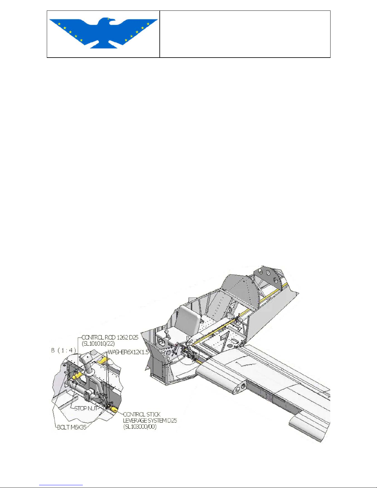
Disconnect aileron control rod from control stick through control stick frontal inspection door,
unscrewing the M6x35 bolt.
Fig.3-1
Page 50
MAINTENANCE MANUAL
STORM Century S-LSA
STORM Century S-LSA STORMAIRCRAFT
Disconnect fuel line through control stick inspection door, marking the inline and outline. Close the
tubes with caps to avoid fuel leaks.
Disconnect right wing pitot tube and all electrical wirings (including fuel sensor floats) from control
stick inspection door. Mark the static and the dynamic lines.
Disconnect flap connection unscrewing the M6x35 bolt from flap.
Disconnect wing rear spar from fuselage unscrewing the M6 bolt through inspection holes behind
the seats.
Fig. 3-2
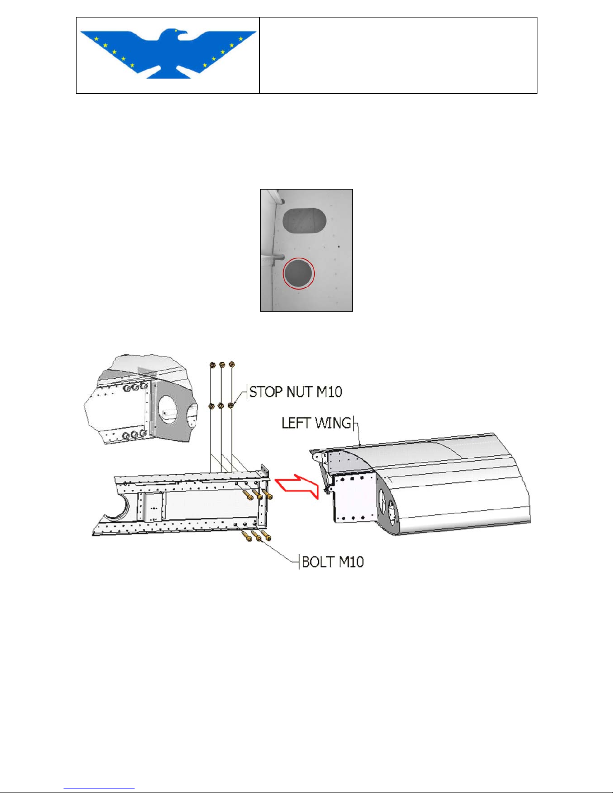
Unscrew the 6 M10x80 bolts from wing box as shown below.
Fig.3-3
Move the wing up and down from wing tip for easy removal.
INSTALLATION
Insert the wing main and rear spars through dedicated housings, passing all tubes and electrical
system cables through housings.
Screw main and rear spars to fuselage with M10x80 bolts for the main spar and with the M6 bolt
for the rear spar.
Connect flap connection to fuselage control bracket and screw with M6x35 bolt.
Connect fuel line tubes and pitot tube through control stick inspection door.
Connect aileron control rod to control stick with M6x35 bolt.
Connect all electrical wirings (including fuel sensor floats).
Page 51
MAINTENANCE MANUAL
STORM Century S-LSA
STORM Century S-LSA STORMAIRCRAFT
3.2.2 FLAP (A&P)
REMOVAL
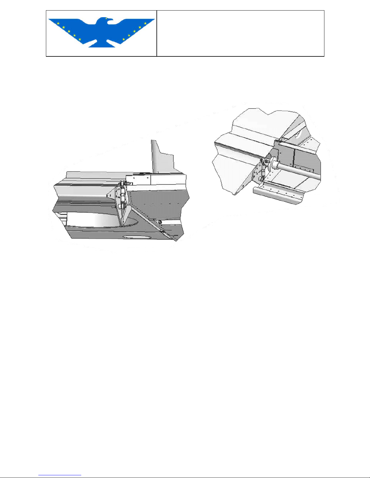
Disconnect the flap from fuselage flap connection if not previously disconnected.
Fig. 3-4
Page 52
MAINTENANCE MANUAL
STORM Century S-LSA
STORM Century S-LSA STORMAIRCRAFT
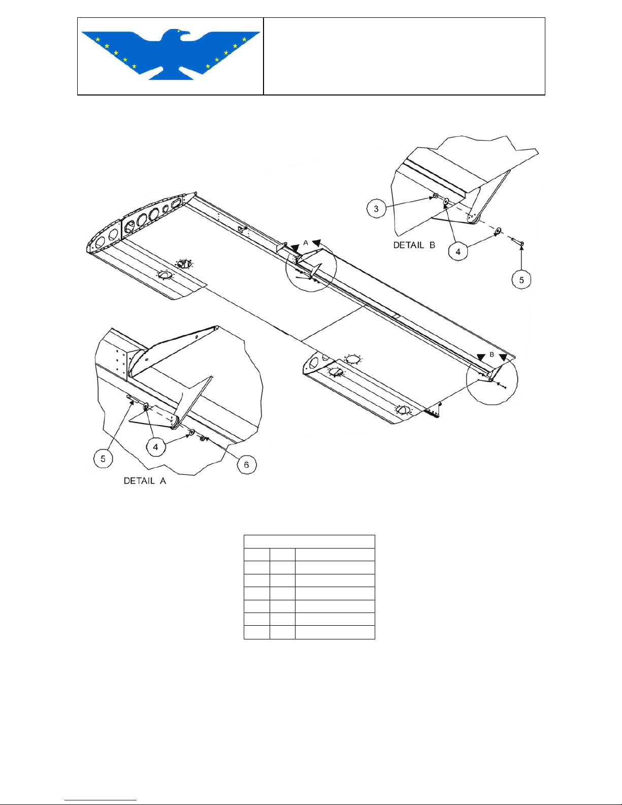
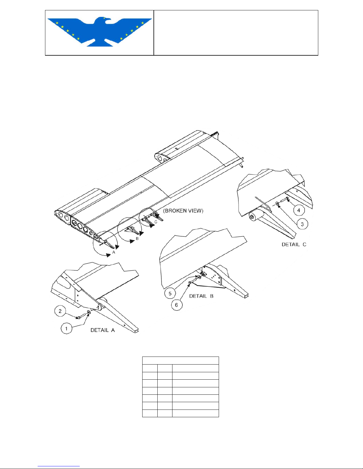
Unscrew the wing-flap connection M5x30 bolts.
Fig. 3-5
PARTLIST
ITEM Q.TY DESCRIPTION
1 2 WASHER M5x15
2 1 BOLT M5x30
3 1 STOP NUT M5
4 2 WASHER M5x15
5 1 BOLT M5x30
6 1 STOP NUT M5
Page 53
MAINTENANCE MANUAL
STORM Century S-LSA
STORM Century S-LSA STORMAIRCRAFT
INSTALLATION
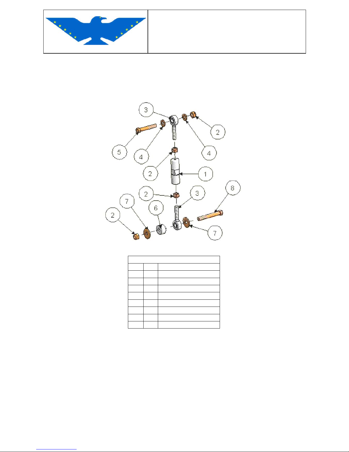
Connect the flap to wing screwing the M5x30 bolts to wing-flap connections.
Connect the flap to fuselage flap connection as described in Wing Removal section (only if wing is
correctly fixed to fuselage).
Fig. 3-6
PARTLIST
ITEM Q.TY DESCRIPTION
1 1 HEXAGONAL SPACER
2 4 STOP NUT M6
3 2 BEARING M6
4 2 WASHER M6
5 1 BOLT M6x35
6 1 SPACER
7 2 WASHER M6x18
8 1 BOLT M6x45
Page 54
MAINTENANCE MANUAL
STORM Century S-LSA
STORM Century S-LSA STORMAIRCRAFT
3.2.3 AILERON (A&P)
REMOVAL
Position flaps at maximum degrees.
Disconnect aileron control rod from aileron unscrewing the M6 bolt from aileron central bearing.
Unscrew the M5x35 bolt from outboard wing-aileron connection and the M6x35 bolt from inboard
wing-aileron connection.
Fig. 3-7
PARTLIST
ITEM Q.TY DESCRIPTION
1 1 WASHER M5x15
2 1 BOLT M5x35
3 1 WASHER M5x15
4 1 BOLT M5x35
5 1 WASHER M5x15
6 1 BOLT M5x35
Page 55
MAINTENANCE MANUAL
STORM Century S-LSA
STORM Century S-LSA STORMAIRCRAFT
INSTALLATION
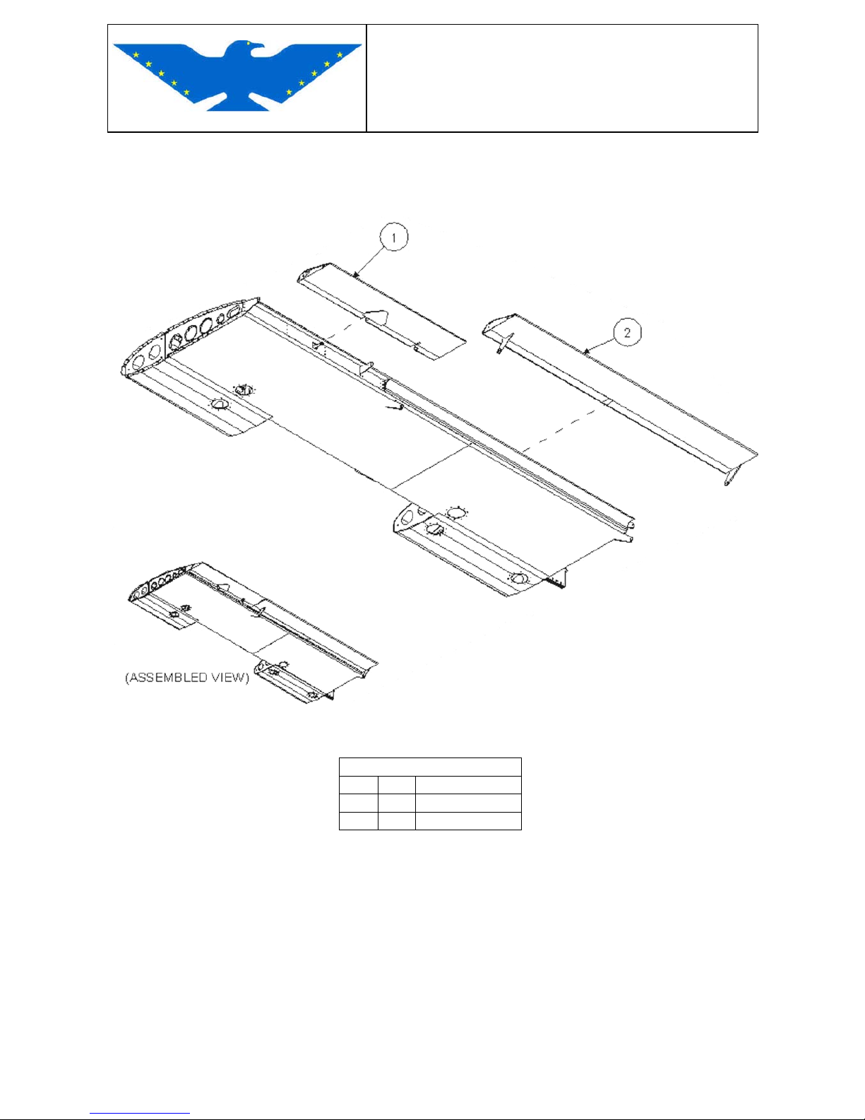
Connect the aileron to wing screwing the M5x35 bolt to outboard wing-aileron connection and the
M6x35 to inboard connection.
Fig. 3-8
PARTLIST
ITEM Q.TY DESCRIPTION
1 1 AILERON
2 1 FLAP
Connect the aileron control rod to aileron central bearing with M6 bolt.
Page 56
MAINTENANCE MANUAL
STORM Century S-LSA
STORM Century S-LSA STORMAIRCRAFT
3.2.4 RUDDER (A&P)
REMOVAL
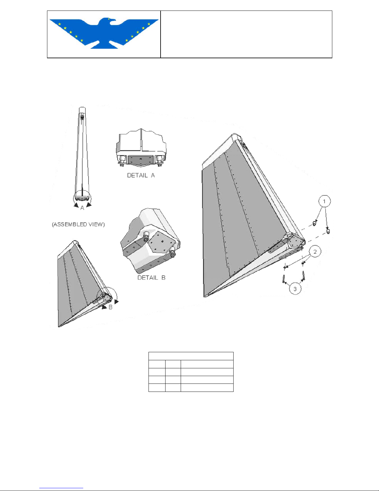
Disconnect the rudder cables from rudder connections unscrewing the M6x45 bolts.
Fig. 3-9
PARTLIST
ITEM Q.TY DESCRIPTION
1 2 SPACER
2 2 WASHER M6
3 2 BOLT M6x45
Unscrew the M6 stop nuts from rudder connections on fuselage fin (the ones with bearings).
Remove the rudder.
Page 57
MAINTENANCE MANUAL
STORM Century S-LSA
STORM Century S-LSA STORMAIRCRAFT
INSTALLATION
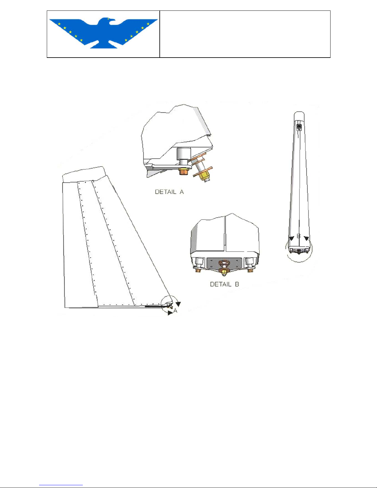
Position the rudder through dedicated bearing connections on fuselage fin.
Screw the rudder pins to fin bearing connections with M6 stop nuts.
Fig.3-10
Page 58
MAINTENANCE MANUAL
STORM Century S-LSA
STORM Century S-LSA STORMAIRCRAFT
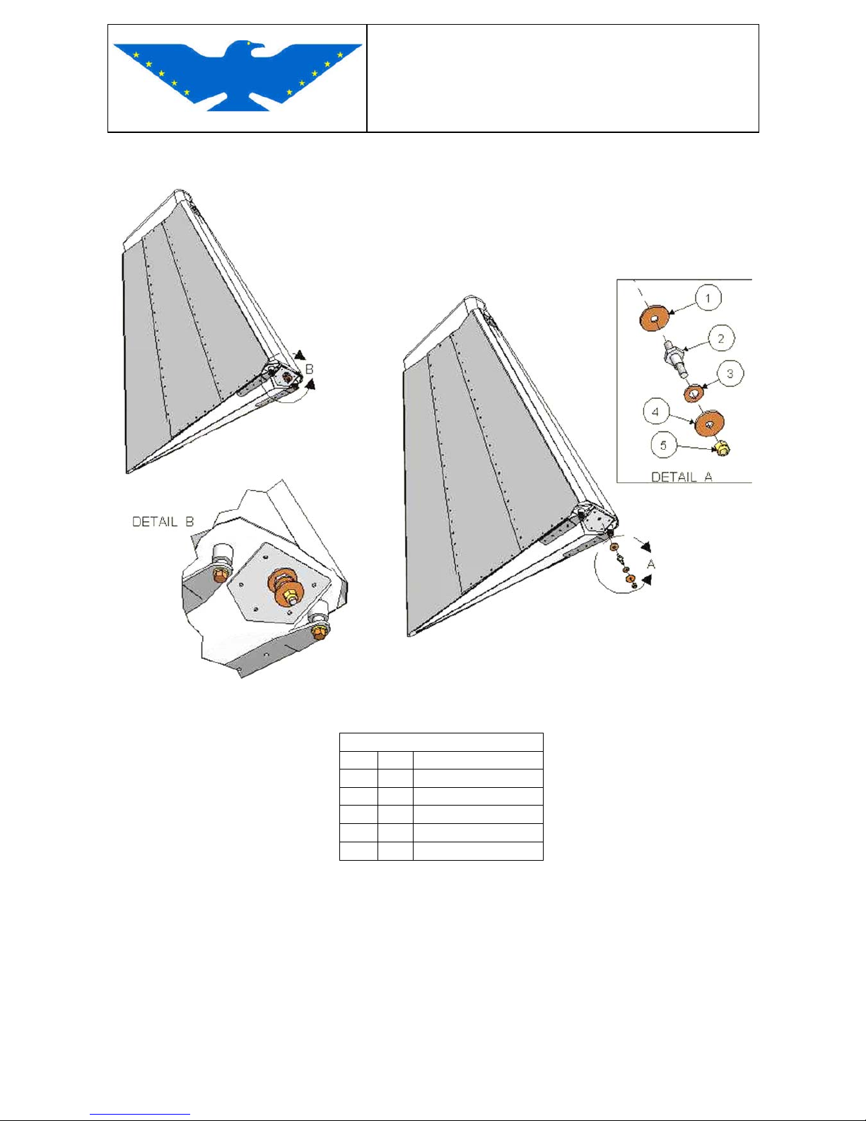
Connect the rudder cables to rudder with M6x45 bolts (remind to insert the spacers).
Fig.3-11
PARTLIST
ITEM Q.TY DESCRIPTION
1 1 WASHER M6x24
2 1 PIN SL401020-05/00
3 1 WASHER M8
4 1 WASHER M6x24
5 1 STOP NUT M6
Page 59
MAINTENANCE MANUAL
STORM Century S-LSA
STORM Century S-LSA STORMAIRCRAFT
3.2.5 RUDDER CABLES (A&P)
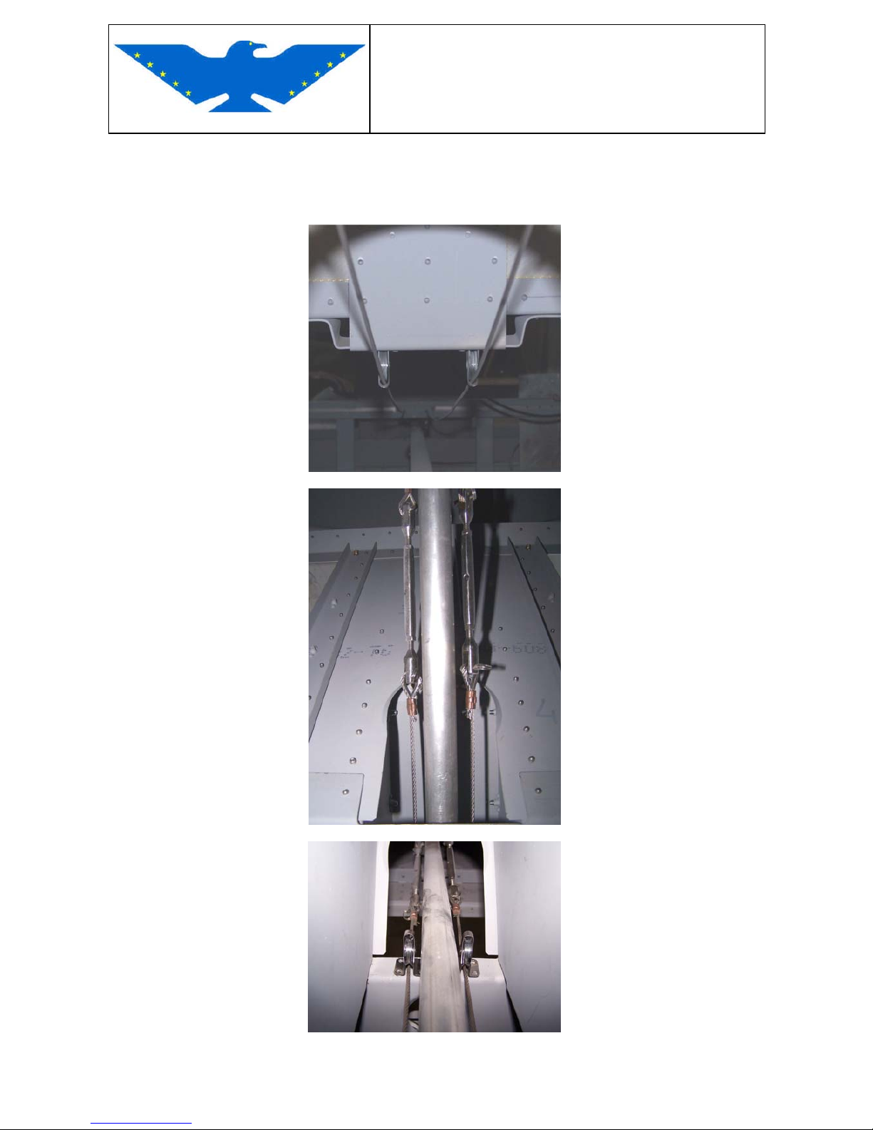
Rudder cables must installed through the snap-in bushings and pulleys positioned inside the
fuselage as shown below. (from fin to pedal)
Fin Pulleys
Baggage bulkhead
Rear console pulleys
Page 60
MAINTENANCE MANUAL
STORM Century S-LSA
STORM Century S-LSA STORMAIRCRAFT
Forward console
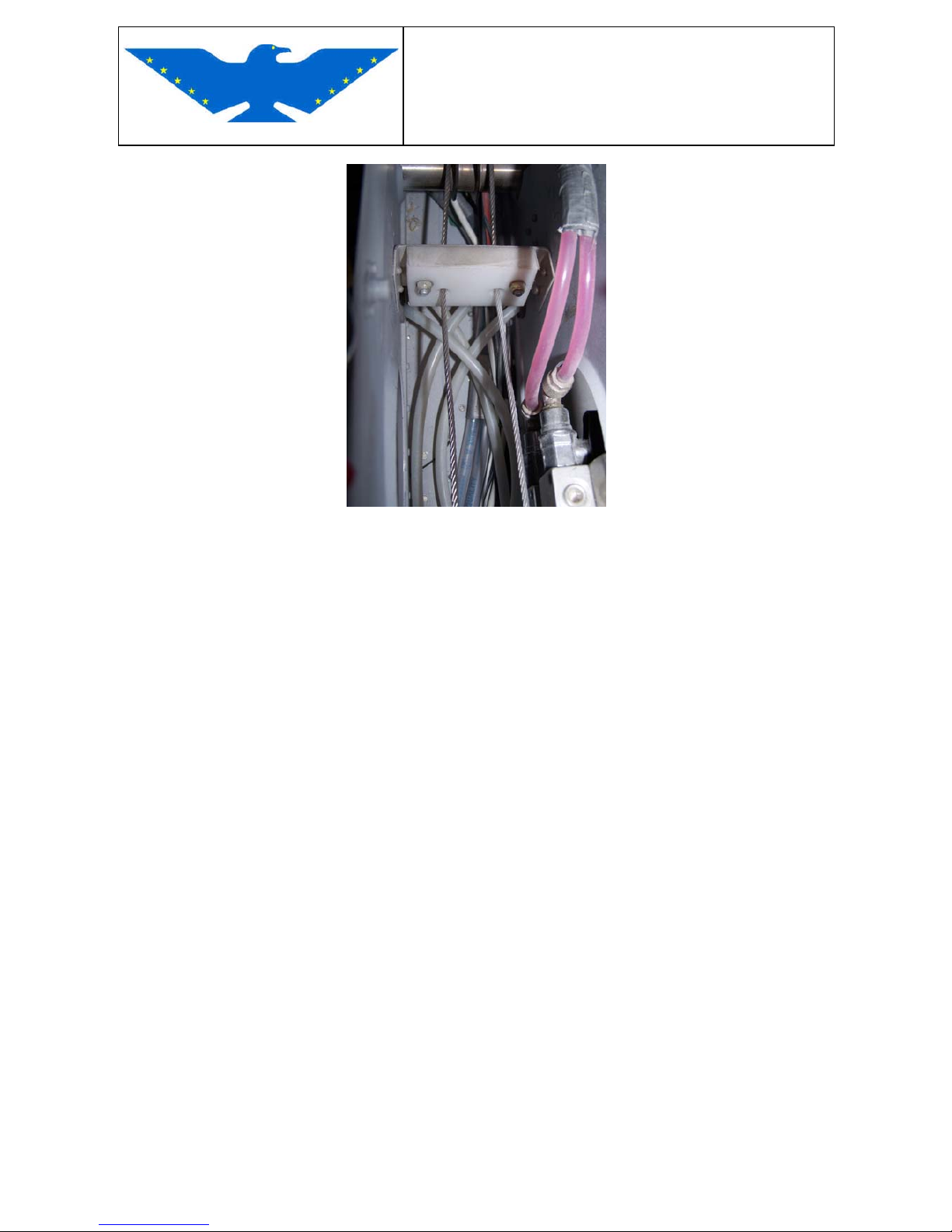
Because of the sizes of the end fittings, the rudder cable must be installed from the rear to the
front, as the front end is the only one with a small enough diameter to pass through the fairleads.
Note that the rudder cables have been assembled with sections of polyethylene tubing on them.
These are used as fairleads where the cable exits the rear fuselage skin.
Page 61
MAINTENANCE MANUAL
STORM Century S-LSA
STORM Century S-LSA STORMAIRCRAFT
3.2.6 STABILATOR (A&P)
REMOVAL
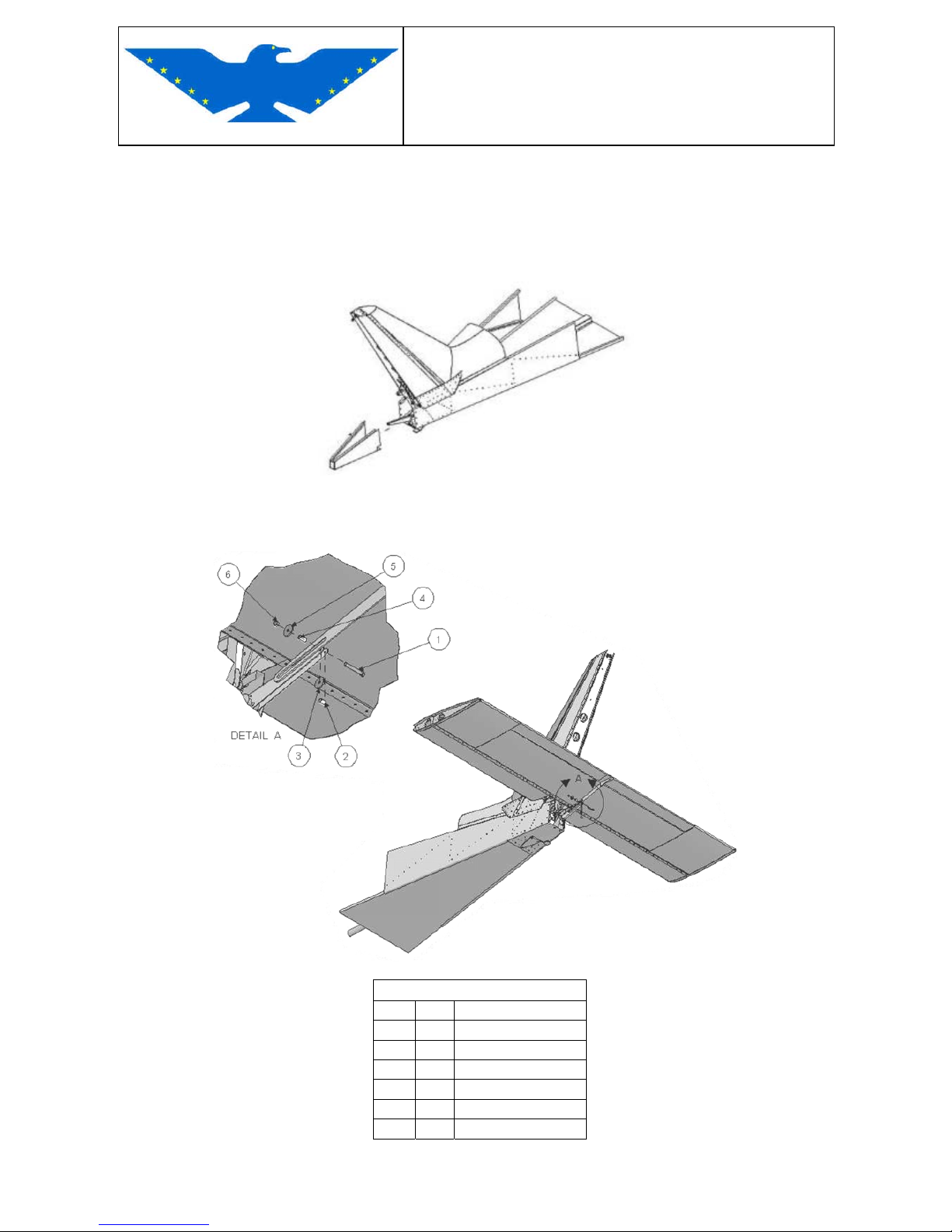
Remove rudder.
Remove tailcone.
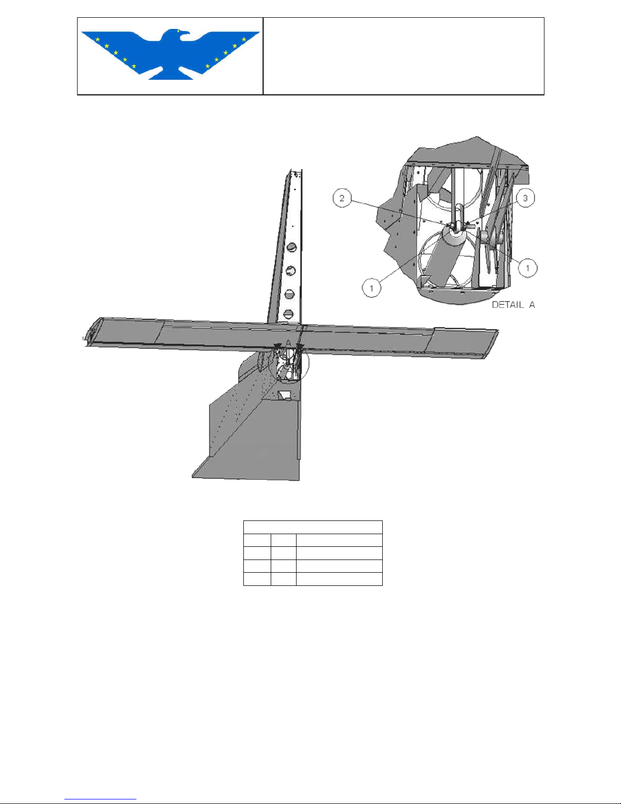
Fig.3-12
Disconnect stabilator electrical trim wiring.
Disconnect stabilator trim tab from fin connection removing the M6x45 bolt.
Fig.3-13
PARTLIST
ITEM Q.TY DESCRIPTION
1 1 BOLT M6x45
2 1 SPACER
3 1 WASHER M6X24
4 1 SPACER
5 1 WASHER M6X24
6 1 STOP NUT M6
Page 62
MAINTENANCE MANUAL
STORM Century S-LSA
STORM Century S-LSA STORMAIRCRAFT
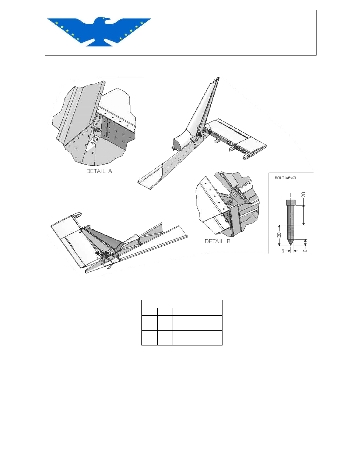
Disconnect stabilator control rod unscrewing the M6x35 bolt from stabilator connection as shown
below.
Fig.3-14
PARTLIST
ITEM Q.TY DESCRIPTION
1 2 WASHER M6
2 1 BOLT M6x34
3 1 STOP NUT M6
Page 63
MAINTENANCE MANUAL
STORM Century S-LSA
STORM Century S-LSA STORMAIRCRAFT
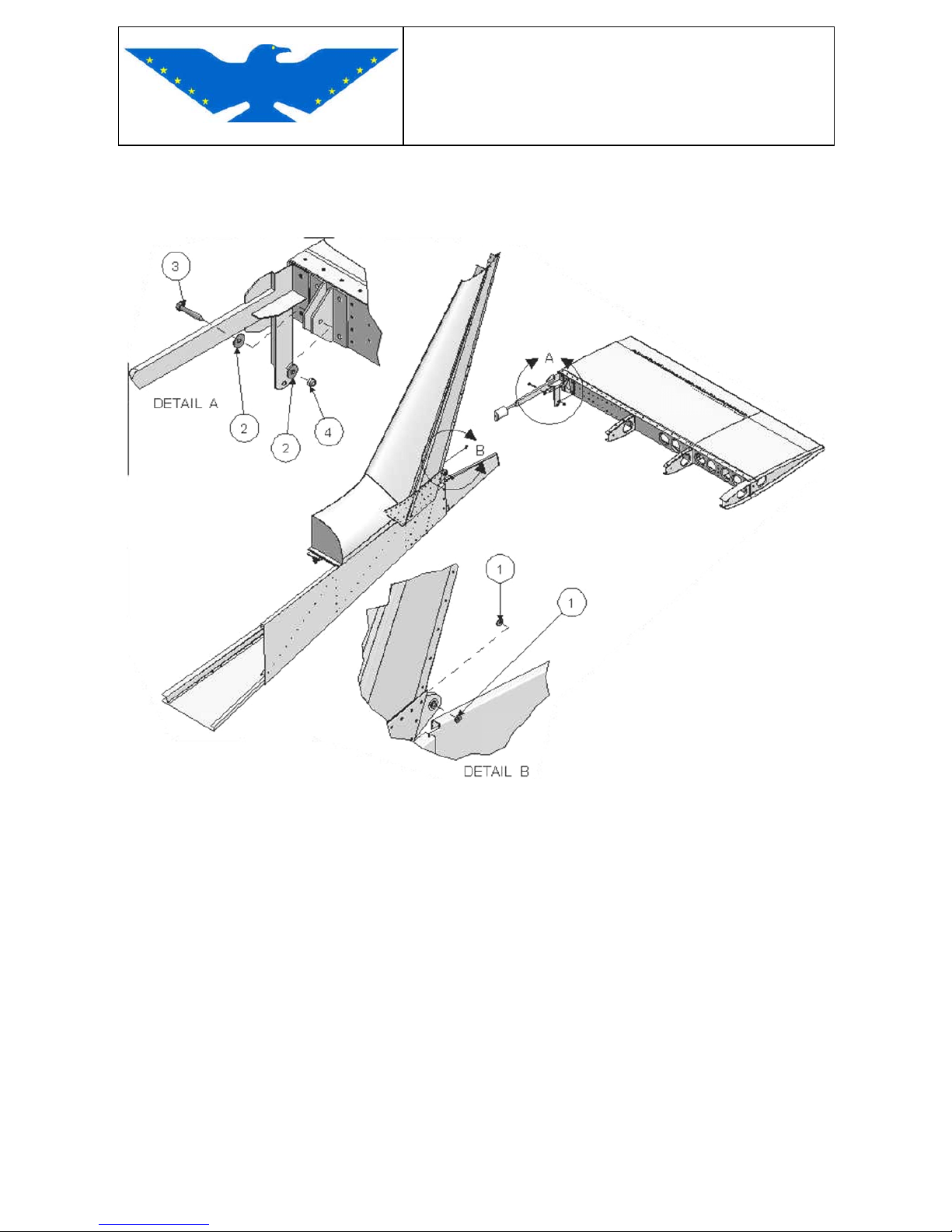
Unscrew the M6x40 bolts from fuselage fin connections.
Fig.3-15
PARTLIST
ITEM Q.TY DESCRIPTION
1 4 WASHER M6
2 4 WASHER M6x24
3 2 BOLT M6x40
4 2 STOP NUT M6
Page 64
MAINTENANCE MANUAL
STORM Century S-LSA
STORM Century S-LSA STORMAIRCRAFT
INSTALLATION
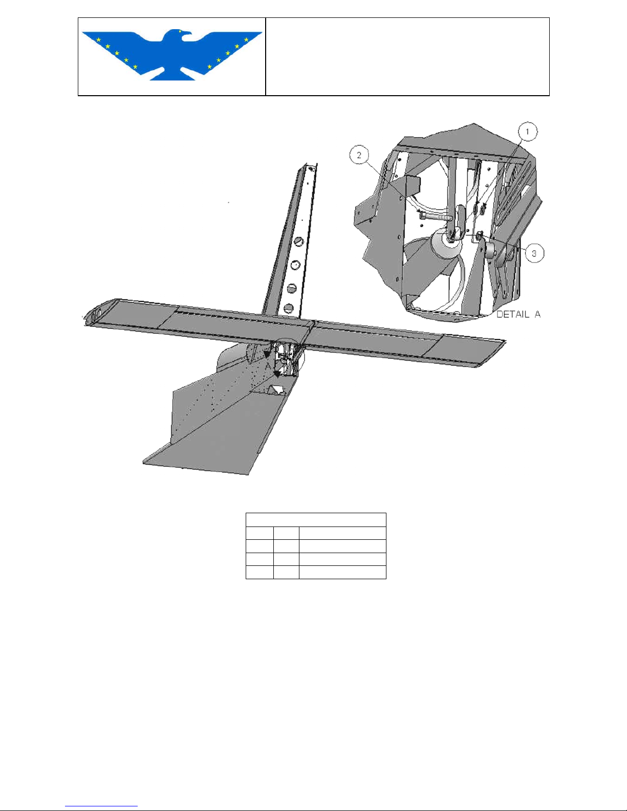
Connect the stabilator to fuselage fin screwing 2 M6x40 bolts to fin connections (the ones with
bearings).
Fig.3-16
Connect stabilator trim tab to fin connection using M6x45 bolt. Align the trim tab at 0° with
stabilator.
Connect stabilator trim wiring.
Page 65
MAINTENANCE MANUAL
STORM Century S-LSA
STORM Century S-LSA STORMAIRCRAFT
Connect the stabilator control rod to stabilator connection with M6x35 bolt.
Fig.3-17
PARTLIST
ITEM Q.TY DESCRIPTION
1 2 WASHER M6
2 1 BOLT M6x34
3 1 STOP NUT M6
Page 66
MAINTENANCE MANUAL
STORM Century S-LSA
STORM Century S-LSA STORMAIRCRAFT
3.2.7 TRIM CONTROL (A&P)
The push buttons on the STICK GRIP control the electric actuator RAY ALLEN 6A of the trim,
transmitting the requested control to the Trim on the Stabilator and, if provided for, to the flattener
tab on the Rudder.
The red push button of the handgrip is used for radio communications (PTT)
The black button is used for the Stabilator trim
• Pushing forward = aircraft nose down
• Pushing backward = aircraft nose up
Two STICK GRIPS are mounted on the aircraft for pilot and co-pilot.
The aircraft attitude can be adjusted with both systems simply pushing the buttons on the STICK
GRIP.
REMOVAL
The electric actuator is installed in the under skin of the RH Stabilator
Remove the screws from the cover.
Turn the cover upside down to reach the wirings
Remove the electric connector
Remove hinge rod (mark its position)
INSTALLATION
Invert removal sequence.
Make sure that the guides of the lower part perfectly fit with the upper part guides without forcing
them and that wirings are not squashed.
Fig. 3-18 TRIM ACTUATOR POSITION
Page 67
MAINTENANCE MANUAL
STORM Century S-LSA
STORM Century S-LSA STORMAIRCRAFT
Fig. 3-19 TRIM TAB ACTUATOR REMOVAL
TRIM CONTROL
SPECIFICATIONS OF “ RAY ALLEN 6 A” ACTUATOR
Operating voltage 12 – 14 Volts DC
No loads current 150 ma
Weight 4.0 oz.
Max Thrust 40 lbs
Output shaft movement 1.0 inch
Output travel time 12 seconds
Construction material 22 c fiber filled nylon
NOTE : should it be necessary to change wires, use a 26 AWG wire like the ones supplied by the
builder. For its length, please refer to drawings.
CAUTION : the pads on the back of the switches are pre bent by the builder to supply the
required clearance. Do not bend backwards and up, they can easily break.
When reassembling the parts, make sure to run wires as per drawings to avoid
to squash them. It’s suggested to follow the builder’s instructions.
Page 68
MAINTENANCE MANUAL
STORM Century S-LSA
STORM Century S-LSA STORMAIRCRAFT
3.3 - CONTROL STOP AND REGULATION (A&P)
RUDDER
Rudder and steerable nose wheel are in the same circuit a bellcrank installed to the pedals
supports two cables move the rudder and two rods through the firewall move the steerable nose
wheel. The regulation of the stops of this system are installed in the connection bracket of the nose
wheel where the pedals rods are fixed.
The right and left stops can be adjusted unloosing the regulation bolt nut and screwing or
unscrewing it according to the required stop adjustment.
Caution: check the Rudder range: 25° RH & LH minimum
AILERON
Its regulation device is on right and left sides of the control stick. The right and left stops can be
adjusted unloosing the regulation bolt nut and screwing or unscrewing it according to the required
stop adjustment.
Caution: check the aileron range
Aileron
12° ± 2° UP 15° ± 2° Down
STABILATOR
Its regulation device is on the pilot grip support facing the center console. The nose-up stop can be
adjusted screwing or unscrewing nut and lock nut, the nose-down stop can be adjusted screwing
or unscrewing nut and lock nut .
Caution: check the stabilizer range
Stabilator
20° ± 2° DOWN 32° ± 2° UP
Page 69
MAINTENANCE MANUAL
STORM Century S-LSA
STORM Century S-LSA STORMAIRCRAFT
3.3.1 LUBRICATION AND CONTROLS CHECK (A&P)
every 100 hours lubricate control hinges and articulations
oil CRC POWER LUBE P/N 09-39605 wires and wire slide
grease LUBRIPLATE No.630AA P/N 09-25400 articulations control bars
hinges
After having performed the 100 hours inspection, make sure that each control in the cockpit is
positioned to grant a comfortable operation and to avoid confusion or involuntary operations.
Controls must be ranged in such a way that, when the pilot is fastened to his seat, all control
movements are free and complete, without being hampered by his garments or by the cockpit
structure.
Make sure that all protection particulars are restored in the cockpit to prevent foreign matters from
jamming the system.
CAUTION : before you install the control protections, make sure you did not forget tools,
bolts or anything else
If during maintenance you installed a locking device on controls, remove locking device before
taking the aircraft to the starting line
CAUTION : do a further check of all controls up to limit stops, they must be free
3.4 LANDING GEAR
MAIN LANDING GEAR DESCRIPTION
The main landing gear has two shock struts made of light alloy which allow to absorb landing
impacts.- The two leaf spring struts are bolted to the central structure of the landing gear on
fuselage L.G. box and rested in special housings on the trestle sides.
Wheels are mounted cantilevered on the struts and are equipped with hydraulic dual caliper disc
brakes controlled by a pump installed in the center console a lever operate the brakes.
(Optionable: two pumps connected to the pilot pedals. Available two additional brakes pump for the
co-piltot).
The main gear wheels have 5 x 5.00" x 6 tires that must be inflated to a pressure of 26 p.s.i. (1,8
bar)
Page 70
MAINTENANCE MANUAL
STORM Century S-LSA
STORM Century S-LSA STORMAIRCRAFT
3.4.1 LANDING GEAR AND BRAKE SYSTEM FAULTS
Possible cause : Remedy :
OWN
- abraded nose gear wheel covering
- replace covering
OWN
- reference signs between wheel and rim of nose gear
shifted
- adjust covering and verify
possible damages of the air
valve
A&P
- the main landing gear wheel is blocked
- brake linings stuck on the disc
- verify tightening of bearings
on the hub, not too tightened
- replace linings and grind disc
A&P
- strong noises rising from the wheels during taxing, like
whistles, etc.
- possible seizing up of
bearings,
faulty brake linings
A&P
- "schimmy" phenomenon on the nose wheel
- too high landing speed,
check the nose gear unit for
possible damages
A&P
- strong vibrations rising from the nose gear unit - check connection of the nose
gear leg
A&P
- brake handle to end of stroke but not braking
- brake fluid leak from pumps or from pipes
- air in the left or right circuit,
bleed the involved air circuit
– if necessary overhaul the
system
3.4.2 MAIN LANDING GEAR REMOVAL (A&P)
- Remove wheel fairing
- It is necessary to lift the aircraft to remove main landing gear (see section: Points of Support)
- Disconnect brake fluid hoses from the leaf spring strut of main gear
- Remove wheel and bearings
- Remove brake calipers
- Unscrew and remove the under Landing Gear Caps.
Page 71
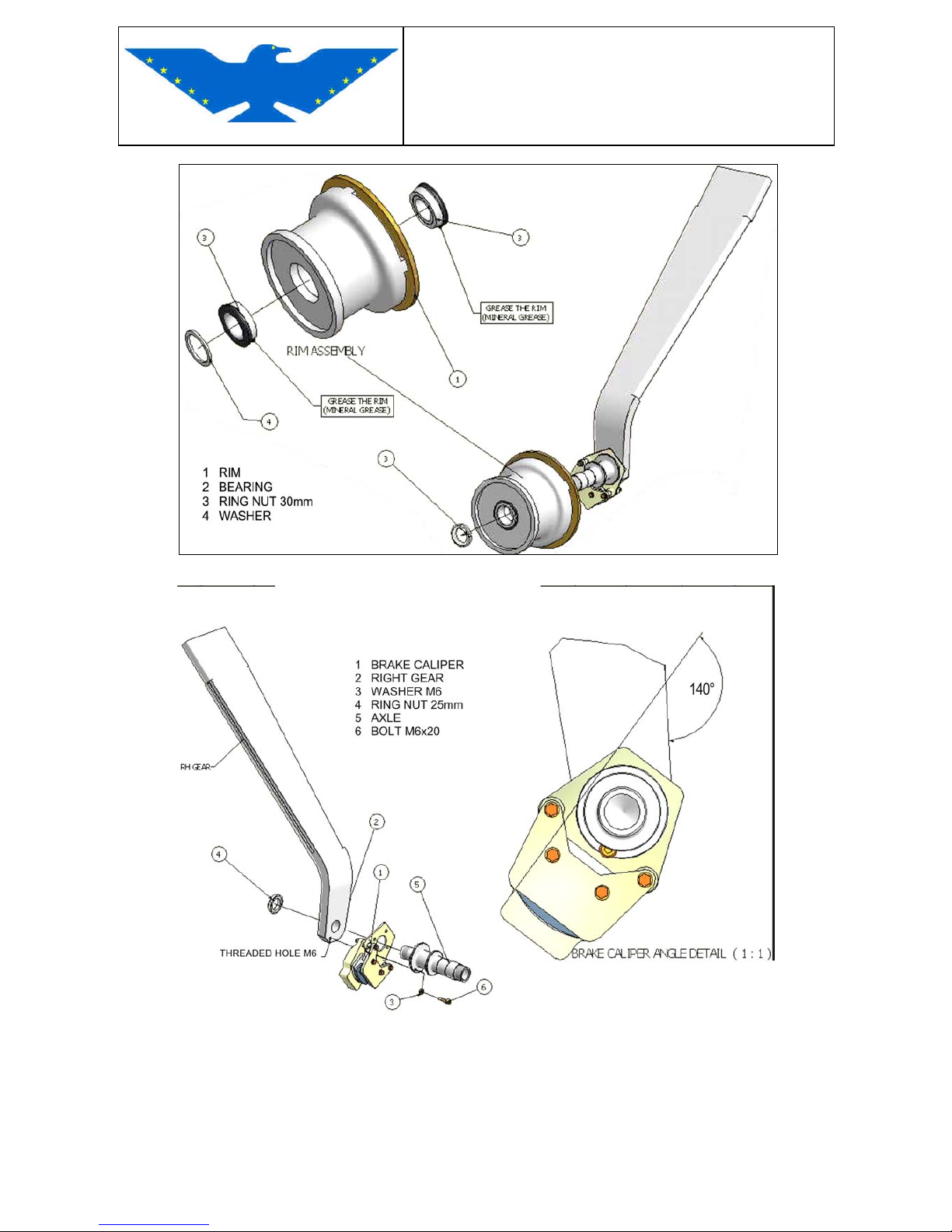
MAINTENANCE MANUAL
STORM Century S-LSA
STORM Century S-LSA STORMAIRCRAFT
Fig. 3-20
Fig. 3-21
CAUTION:
All screws fastening landing gear to fuselage must be changed when removed. Self-locking
nuts must be changed when released; pin locks shall be changed, not reutilized.
Tighten all screws up to correct torque value.
Page 72
MAINTENANCE MANUAL
STORM Century S-LSA
STORM Century S-LSA STORMAIRCRAFT
LUBRICATION
All bearings are "long life", they do not require special lubrication; if necessary, use LUBRIPLATE
NO. 630AA p/n 09-25400 for lubrication.
Change wheel bearings every 100
0 hours.
WARNINGS
CAUTION
SHOULD A BUMPY LANDING OCCUR OR ANYTHING ELSE THAT MAY CAUSE DAMAGES
TO THE LANDING GEAR STRUCTURE, YOU SHALL:
1 – Make sure that the fuselage part where the landing gear structure is assembled, is not
damaged or warped.
2 – Remove the whole landing gear unit and check all fuselage connections
3 – Replace damaged part
4 – Install the landing gear assembly in its seat
5 – Landing gear measurements shall fall within tolerances
Page 73
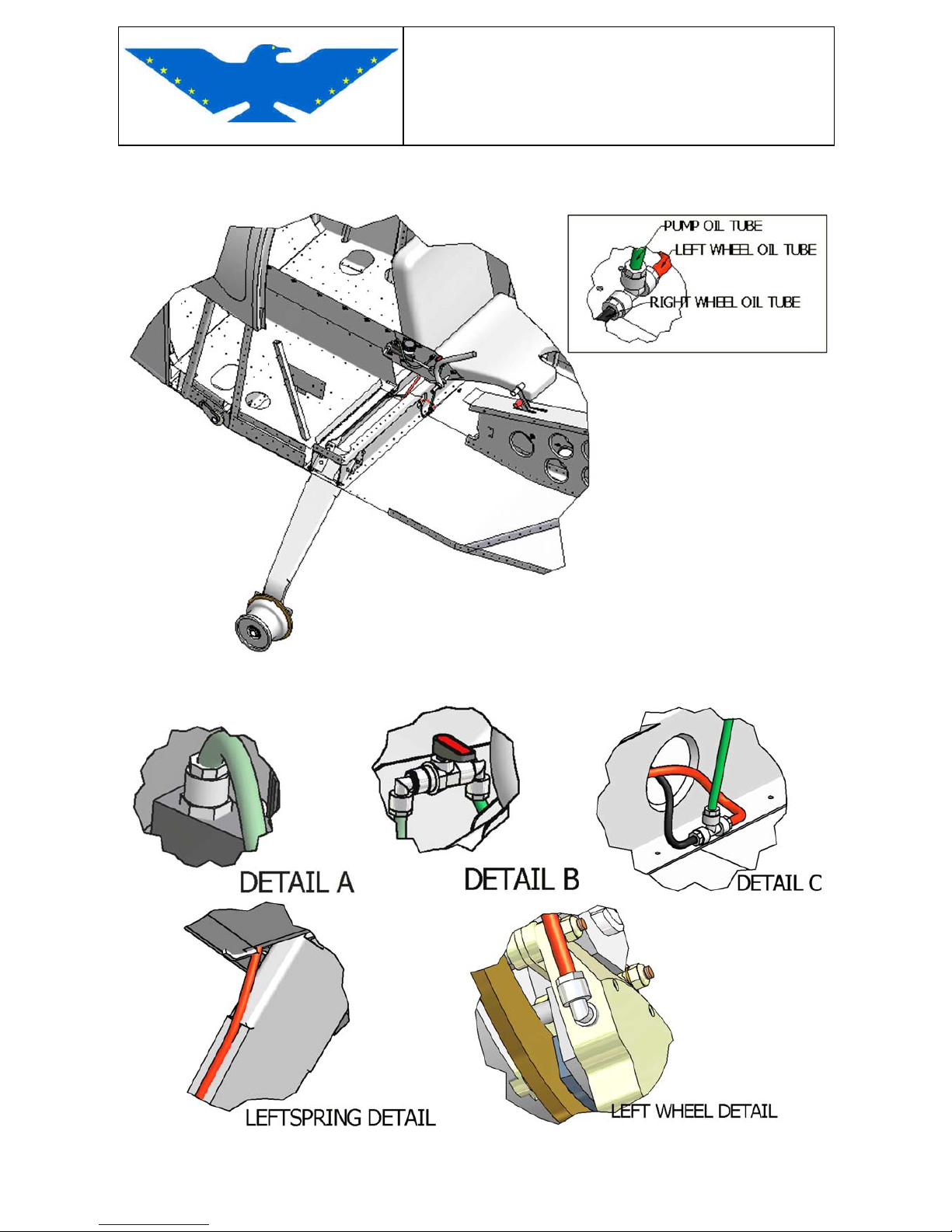
MAINTENANCE MANUAL
STORM Century S-LSA
STORM Century S-LSA STORMAIRCRAFT
3.4.3 BRAKE SYSTEM (with Toe brakes) (A&P)
Fig. 3-22
Fig. 3-23
Page 74
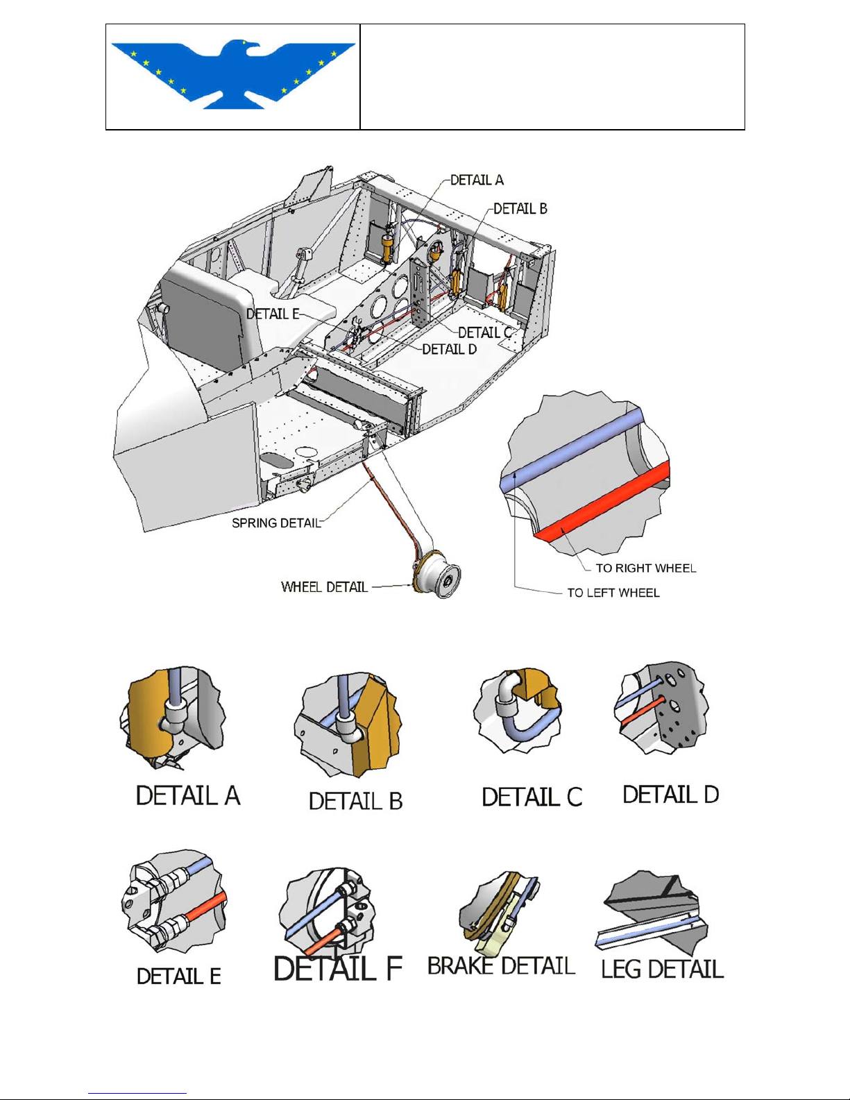
MAINTENANCE MANUAL
STORM Century S-LSA
STORM Century S-LSA STORMAIRCRAFT
Fig. 3-24
Fig. 3-25
Page 75
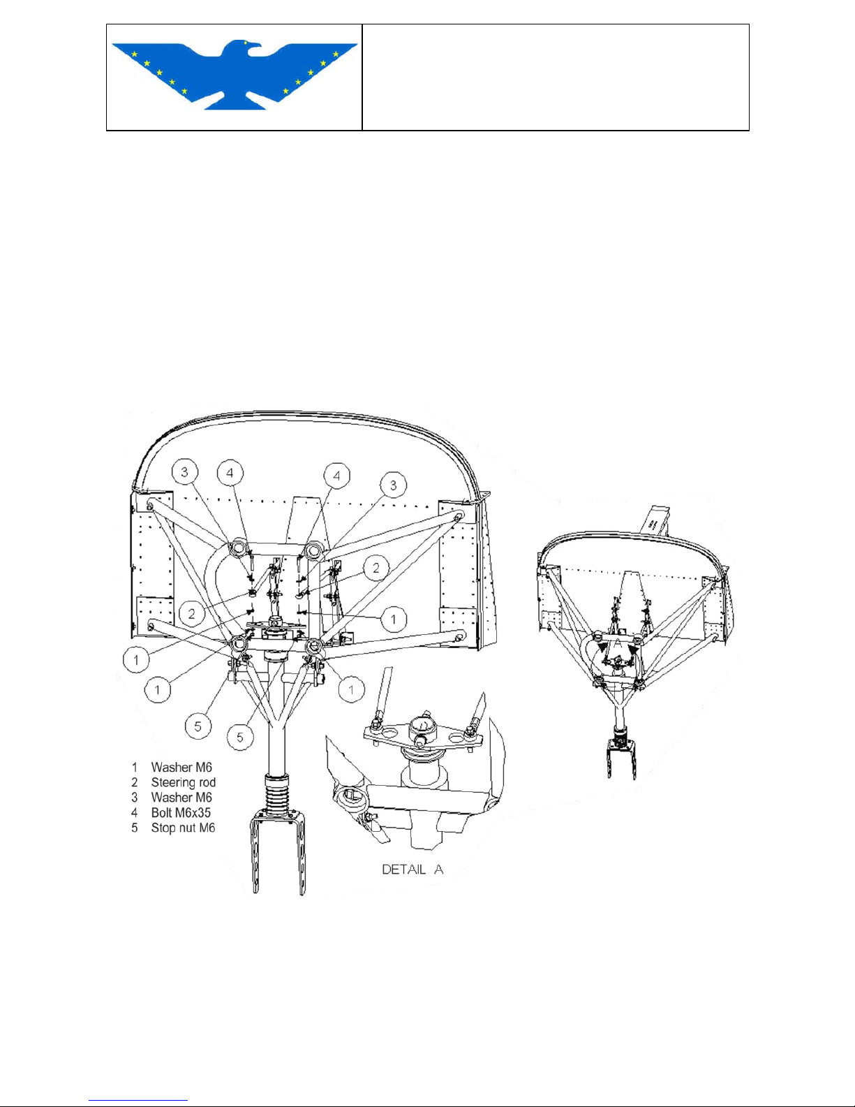
MAINTENANCE MANUAL
STORM Century S-LSA
STORM Century S-LSA STORMAIRCRAFT
3.5 STEERABLE NOSE GEAR
STEERABLE NOSE GEAR DESCRIPTION
The steerable nose gear is bolted to the engine cradle; a removable bracket on the top is
connected to the rudder pedals with two bars with adjustable end bearing. Two springs fixed to the
pedals, also adjustable, keep in flight, the nose wheel straight when the wheel fairing is installed. A
series of shock absorber are installed to the gear strut to cushion. The rubber shock absorbers
must be replaced every 400 hours heavy landing excepted. the lubrication of the visual parts must
be done every 100 hours to the inside strut and the bushing every 500 hours.
NOTE: Protect the rubber shock absorber from grease and lubricant.
The nose gear wheels have 4 x 4.00" x 6 tires that must be inflated to a pressure of 26 p.s.i. (1,8
bar).
Fig. 3-26 STEERABLE NOSE GEAR
Page 76
MAINTENANCE MANUAL
STORM Century S-LSA
STORM Century S-LSA STORMAIRCRAFT
3.5.1 STEERABLE NOSE GEAR REMOVAL (A&P)
REMOVAL
- Remove the cowling
- Remove wheel fairing
- It is necessary to lift the aircraft to remove nose landing gear. Position tail down (see chapter:
Points of Support)
- Remove nose wheel and axle
- Disconnect the steerable control rods
- Remove the 2 FW. M 6 bolts and the 2 M8 AFT bolts from the engine cradle.
- Withdraw nose gear assembly from engine cradle.
INSTALLATION
- Invert removal sequence
CAUTION: All screws fastening nose gear to fuselage must be changed when removed.
Self-locking nuts must be changed when released; pin locks shall be changed, not
reutilized.
Tighten all screws up to correct torque value.
LUBRICATION
All bearings are "long life", they do not require special lubrication; if necessary, use LUBRIPLATE
NO. 630AA p/n 09-25400 for lubrication.
Change wheel bearings every 1000 hours.
WARNINGS
CAUTION
SHOULD A BUMPY LANDING OCCUR OR ANYTHING ELSE THAT MAY CAUSE DAMAGES
TO THE NOSE GEAR STRUCTURE, YOU SHALL:
1 – Make sure that the engine cradle part where the nose gear structure is assembled, is not
damaged or warped.
2 – Disassemble the whole nose gear unit and check all parts.Don’t forget to mark the
rubber shock absorbers and plastic washers position.
3 – Replace damaged part
4 – Install the landing gear assembly in its seat
5 – Nose gear measurements shall fall within tolerances
Page 77
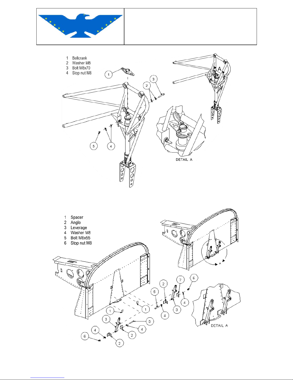
MAINTENANCE MANUAL
STORM Century S-LSA
STORM Century S-LSA STORMAIRCRAFT
Fig. 3-27 REMOVING NOSE GEAR
PEDALS/NOSE WHEEL HINGES CONNECTION
Fig. 3-28 PEDALS LEVERAGE FIREWALL CONNECTION
Page 78
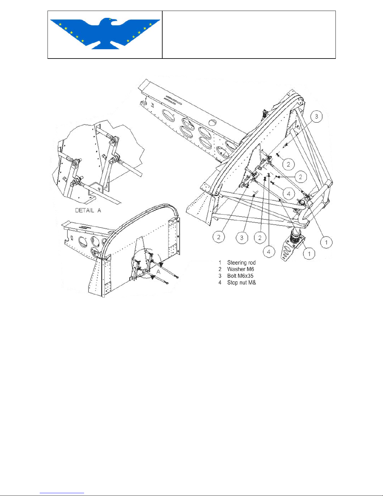
MAINTENANCE MANUAL
STORM Century S-LSA
STORM Century S-LSA STORMAIRCRAFT
PEDALS/NOSE WHEEL CONNECTION
Fig. 3-29 PEDALS/NOSE WHEEL BRACKETS CONNECTION
Page 79
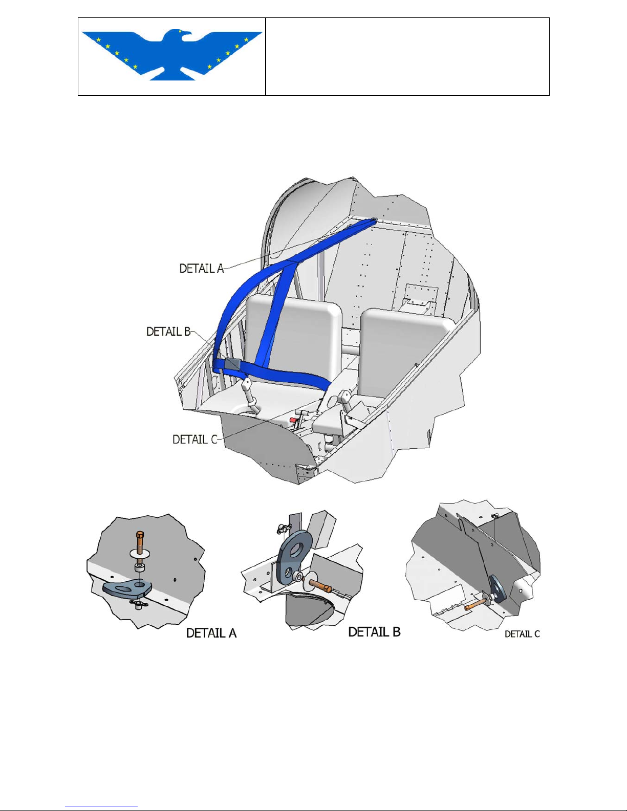
MAINTENANCE MANUAL
STORM Century S-LSA
STORM Century S-LSA STORMAIRCRAFT
3.6 SEAT BELTS
SEAT BELTS INSTALLATION
Fig. 3-30
Screw the M6 bolts to dedicated anchor nuts installed on baggage bulkhead (detail A), fuselage
side (detail B) and central console (detail C).
Page 80
MAINTENANCE MANUAL
STORM Century S-LSA
STORM Century S-LSA STORMAIRCRAFT
4 ENGINE
See Rotax Maintenance Manuals provided with this manual.
5 FUEL SYSTEM
The fuel system is connected to 2 wing tanks. In normal operating conditions, an AC pump located
on the left of the engine in an advance position supplies fuel to the carburetors. From the wings the
fuel go to a little tank installed in the upper side of the firewall inside the cabin from here to the
shut-off valve in the FW center consol with two positions: open/closed ; then to the gascolator filter
located in the lower left part of fuselage on the firewall. The gascolator also has a bleeding. The
fuel flows then from the gascolator to the electric pump controlled by the pilot, located on top of it,
then to the mechanical pump driven by the engine and then to the switch. From the switch, located
on the upper part of the circuit, the fuel reaches the carburetors. Some of this fuel starts the fuel
pressure gauge up, and the exceeding part flows back through the top of the wing tanks . Should
one of these pumps fail, feed is guaranteed by the other one. We suggest you to operate the
electric pump during take-off and landing.
In the switch fuel return line, there is installed a Jet with 1mm hole : clean each 300 hours.
NOTE : we suggest you to keep tank always full so as to avoid humidity condensation
inside. Always fill with previously filtered and clean fuel.
Description of fuel system drawing:
01 - Fuel filler on top of left side of fuselage
02 - Fuel tanks
03 - Fitting and decantation tank
04 - Bleeding screw
05 - Two ways feed cock ON/OFF
06 - "gascolator" carburetor filter
07 - Bleeding screw
08 - Electric pump
09 - Mechanical pump
10 - Switch
11 - Carburetor
12 - Carburetor
13 - Fuel pressure gauge
14 - Return flow pipe
Page 81
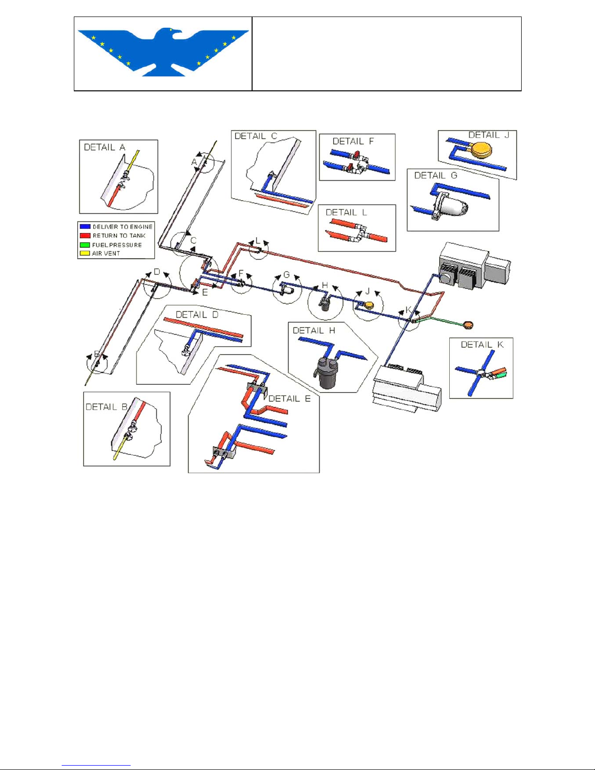
MAINTENANCE MANUAL
STORM Century S-LSA
STORM Century S-LSA STORMAIRCRAFT
5.1 FUEL SYSTEM
Fig.5-1 FUEL SYSTEM DIAGRAM
Page 82
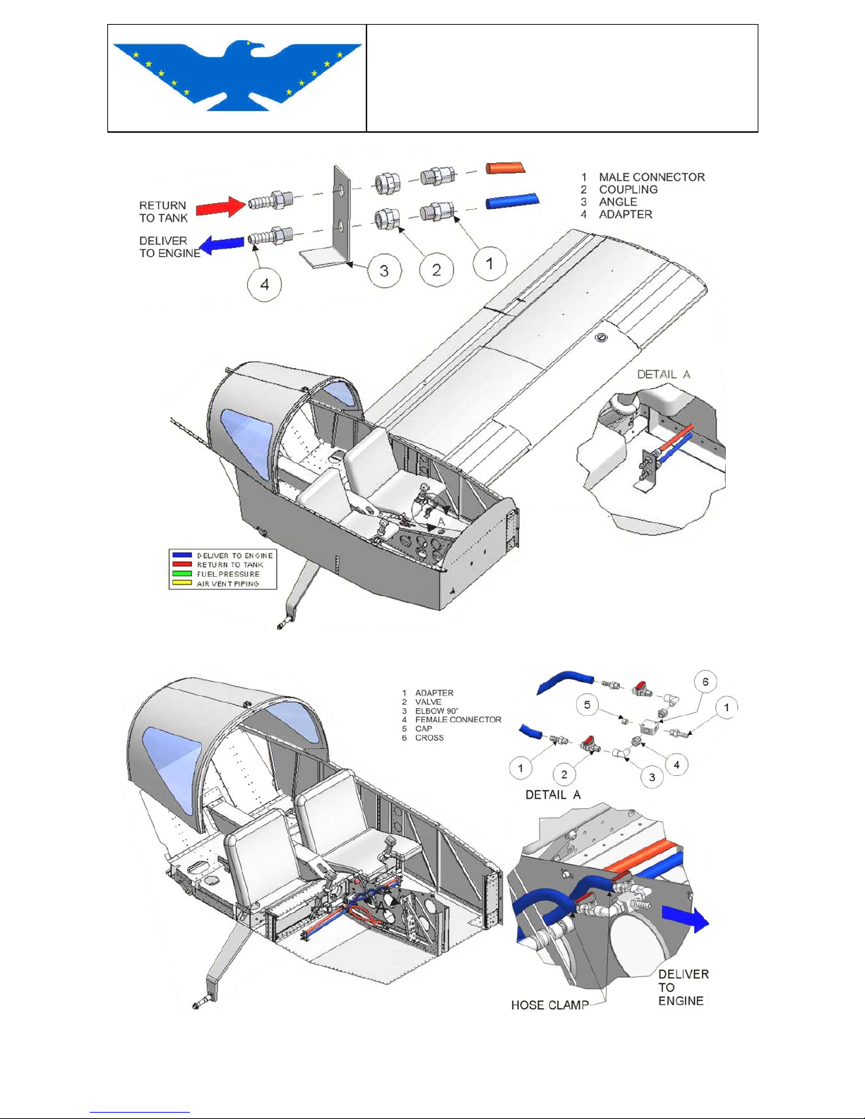
MAINTENANCE MANUAL
STORM Century S-LSA
STORM Century S-LSA STORMAIRCRAFT
Fig.5-2 FUEL LINE FROM WING TO FUSELAGE FLOOR FITTINGS
Fig.5-3 DELIVER FROM FUSELAGE FLOOR TO CENTRAL CONSOLE VALVES
Page 83
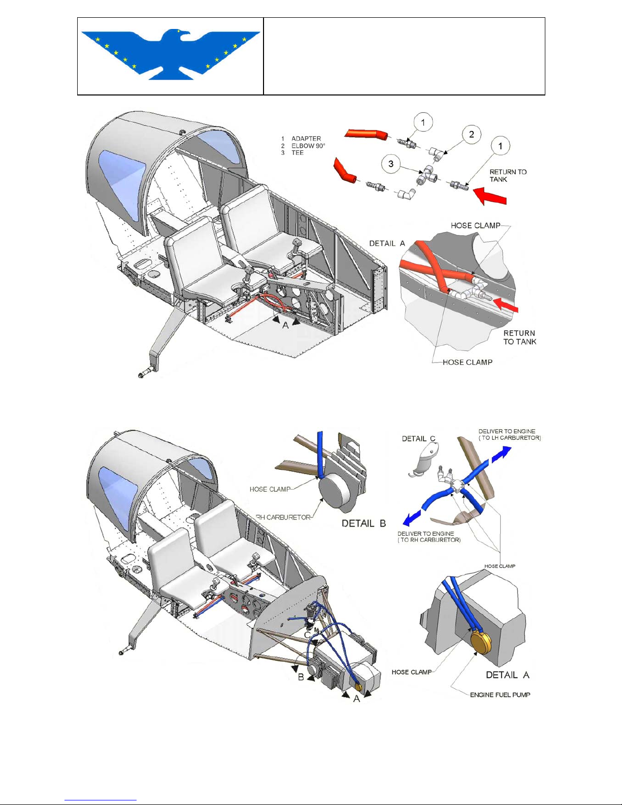
MAINTENANCE MANUAL
STORM Century S-LSA
STORM Century S-LSA STORMAIRCRAFT
Fig.5-4 RETURN FROM FUSELAGE FLOOR TO CENTRAL CONSOLE VALVES
Fig.5-5 DELIVER FROM FIREWALL TO ENGINE
Page 84
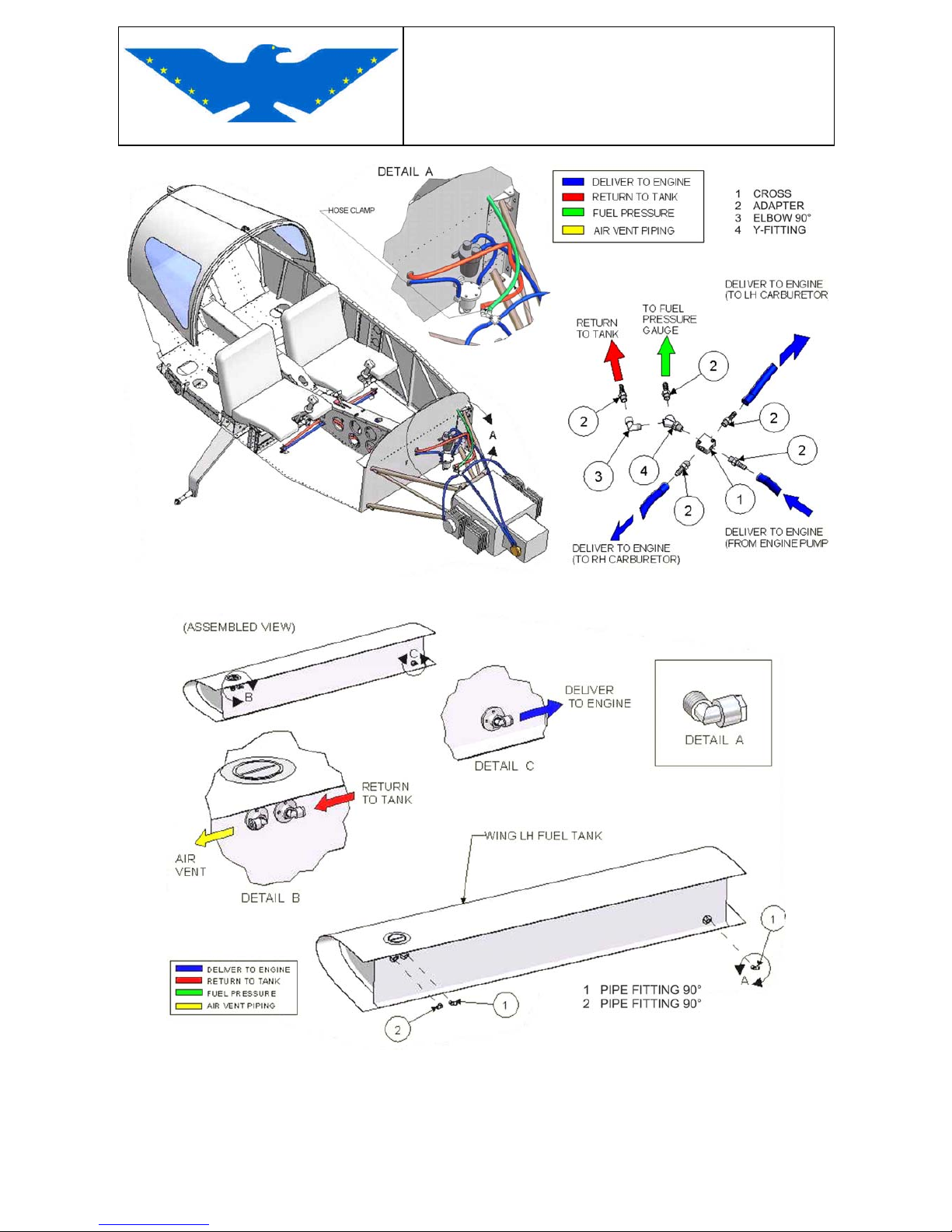
MAINTENANCE MANUAL
STORM Century S-LSA
STORM Century S-LSA STORMAIRCRAFT
Fig.5-6 FUEL LINE FROM FIREWALL TO ENGINE
Fig.5-7 WING TANKS FUEL LINE FITTINGS
CAUTION: Should fuel marks or drippings be noticed on the central part of fuselage, an immediate
check will be necessary in order to find out the origin of drippings and carry out the necessary
repairs.
Page 85
MAINTENANCE MANUAL
STORM Century S-LSA
STORM Century S-LSA STORMAIRCRAFT
REMOVAL
Disconnect battery
Empty tank completely using the bleeding screw under the tank on the decantation tank; open also
the bleeding screw under the gascolator.
CAUTION: keep fire extinguisher within reach when draining the tank, take all necessary
precautionary measures, keep the area ventilated.
Disconnect fuel feed/return flow pipes
CAUTION: if you do not expect to change the fuel pipes, we suggest to close them with a pin of the
same size as the inside diameter of the pipe.
INSTALLATION
a) carefully clean the inside of the tank from any processing residual, make sure that the breather
is free.
b) invert the sequence for installation
5.2 FUEL SYSTEM FITTINGS
GASCOLATOR FUEL FILTER
(DETAIL G - FUEL LINE DIAGRAM)
The gascolator, containing 0,13 gal fuel, is in the lowest part of the fuel circuit, on the firewall. The
fuel filter is inside the gascolator.
The gascolator has a pressure bleeding where the condensation residuals are collected; it can be
reached from the lower outside part of the nacelle.
ELECTRIC FUEL PUMP
(DETAIL H - FUEL LINE DIAGRAM)
This pump is used as auxiliary or emergency pump which can be turned on during take-off or
landing or in particular emergency conditions. The operation of this pump works on the vibrating
movement of a diaphragm cylinder which creates suction and pressure; its movement is controlled
by an electromagnet.
MECHANICAL FUEL PUMP
The mechanical diaphragm pump is controlled directly by the engine. When the engine is on, the
mechanical pump sucks fuel through the electric fuel pump, and sends it to the carburetors with a
pressure of about 0,15 - 0,4 bar (2.2 - 5.8 p.s.i.).
Page 86
MAINTENANCE MANUAL
STORM Century S-LSA
STORM Century S-LSA STORMAIRCRAFT
FUEL SHUT – OFF VALVE
The two ways shut of valve is controlled by an OPEN / CLOSED switch on the central console, in
front of the throttles.
FUEL PIPES
From wing tanks to the auxiliary tank : Rilsan 8/6 mm
From the auxiliary tank through the firewall rubber fuel pipe inside diameter 7 mm.
Caution: use only piping agreed for unleaded fuel
FLOAT
If installed It is accessible through the inspection hole on the wing.
To remove you must disassemble the wing (see Chapter 3.2.1)
5.2.1 FITTING REMOVAL AND INSTALLATION
CAUTION : before you proceed with the removal of: gascolator, electric pump, mechanical
pump and feed cock, the remaining fuel must be drained from the tank.
REMOVAL
Gascolator, electric pump, mechanical pump :
a) close feed cock
b) disconnect fuel pipes
c) disconnect electrical system from electric pump
d) remove locking nuts from firewall and engine
CAUTION: should a malfunction of the mechanical pump occur, it cannot be repaired. It has to be
replaced.
INSTALLATION
gascolator, electric pump, mechanical pump :
invert removal sequence
Page 87
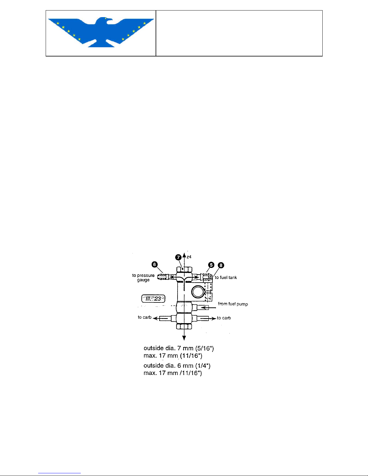
MAINTENANCE MANUAL
STORM Century S-LSA
STORM Century S-LSA STORMAIRCRAFT
5.3 SHUT OFF FUEL VALVE
REMOVAL
a) remove top screw of selector
b) unloose the socket head screw on the stainless steel pipe, insert setscrew wrench from special
trapdoor on the console side
c) disconnect fuel pipes from cock
d) unscrew metal pipes from cock
e remove cock from its housing
INSTALLATION
a) invert removal sequence
b) make sure that the selector ON/OFF position matches the OPEN/CLOSED position of the cock
c) the hose clamps must be changed when operating on the cock
d) mark all screws with anti-sabotage material
5.4 FUEL SWITCH
Drawing of fuel switch (from Bombardier-Rotax)
Page 88
MAINTENANCE MANUAL
STORM Century S-LSA
STORM Century S-LSA STORMAIRCRAFT
CARBURETOR
Description : two vacuum carburetors "Bing 64/32": the incoming air sucks the membrane which
causes valve and needle to rise.
There is no drive of the mixture control (MIXER); the carburetor valve is controlled by the vacuum
created on a membrane by the air taken in by the carburetor and not by a manual gear (wire or stiff
rod). When the carburetor is set in a correct way, the stoichiometric proportion air/carburetor is
steady.
The synchronization of the carburetors must be performed by Rotax technical staff, using the
vacuometer sockets under the suction ducts. The carburetor setting is fixed and predetermined
with only one variant: the needle position may be changed.
The carburetor has a circuit for cold start to enrich the air/fuel mixture controlled through the
STARTING CARB. lever, working on an idling circuit duct.
CAUTION : some total or partial breakaways of the carburetors were supposed to be due
to wrong installation, to vibrations caused by unbalanced propellers and to a bad
synchronization of carburetors with subsequent engine bumping.
Frequent checks must be carried out. Leave a 7mm opening on the clamp for normal
tightening; the clamp must be original and with its screw facing down.
The carburetor has also an overflow in the fuel bleeding system.
CAUTION : do not throttle overflow pipes in any way, make sure that they do not dump fuel
directly on or near the exhaust manifolds.
5.5 FUEL AND AIR CIRCUIT IN THE CARBURETOR
The fuel circuit is made of a needle valve operated by the rocker controlled by floats located in
the chamber. The fuel level in the chamber must be steady: floats which open and close the needle
valve keep a steady fuel inflow to the engine.
The fuel level in the chamber can be modified if necessary.
CAUTION : modifying the fuel level will affect the titer of the air/fuel mixture
Lowering the fuel level in the chamber as to normal, the carburetion will be leant.
Increasing the fuel level in the chamber as to normal, the carburetion will be richer.
The fuel level must be measured from the upper chamber lip and it must be about 12 - 13 mm.
The air circuit is basically made of a suction filter and of the conduct conveying air to the engine.
The purpose of this filter is to avoid that impurities get into the engine. The paper filter may be
cleaned with a special detergent: "Filter Clean" ; it must be used strewing the filter both inside and
outside, leaving it on for 10 minutes. The filter must then be plunged into a basinful of water and
finally carefully rinsed with water avoiding to scrub it. The filter must be dried in quiet air.
Do not use compressed air to dry the filter.
Page 89
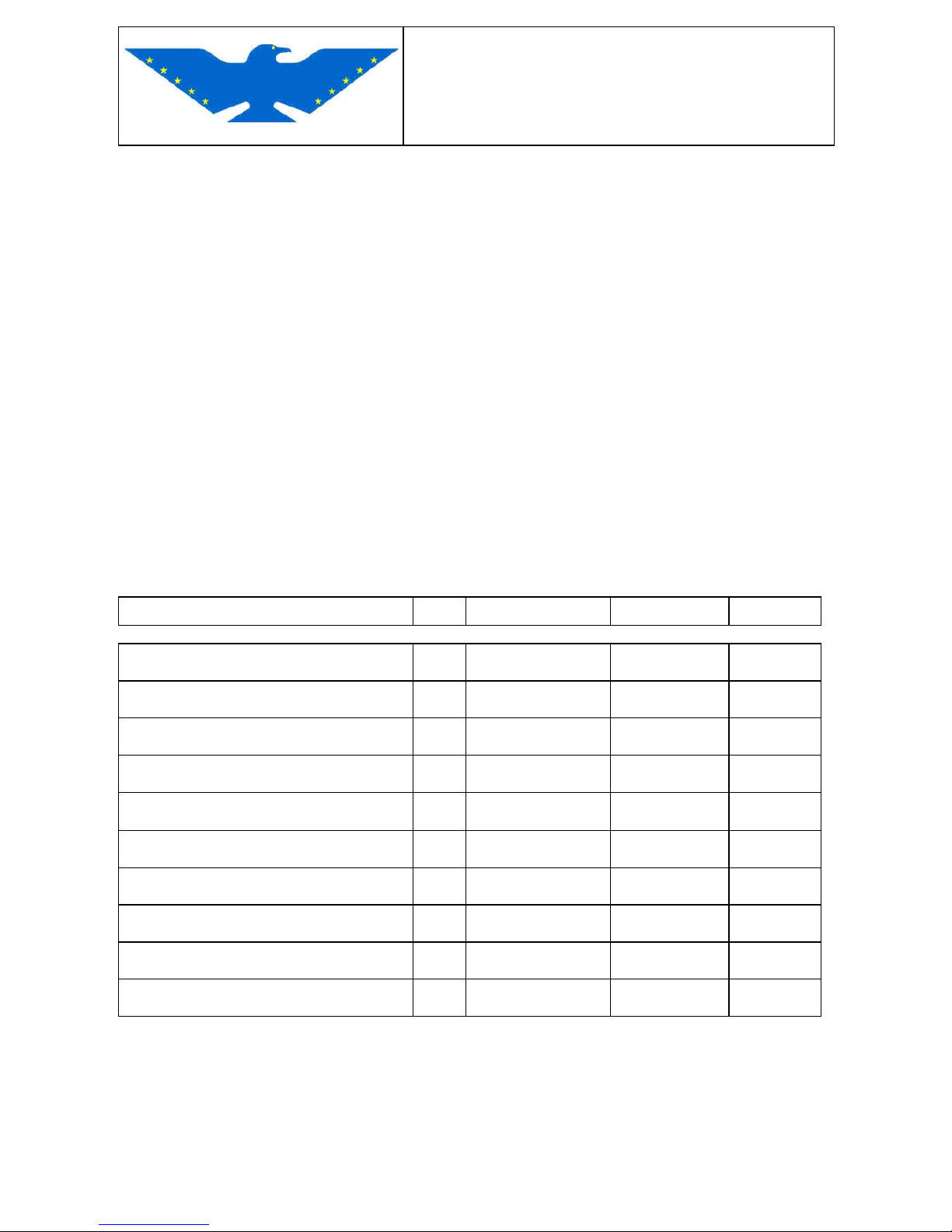
MAINTENANCE MANUAL
STORM Century S-LSA
STORM Century S-LSA STORMAIRCRAFT
WARM AIR
Storm Century does not require the use of warm air to carburetor, since it utilizes a simple “warm
air " system.
The "warm air" system avoids the need for a heat exchanger, taking air directly from the engine
compartment. In this way, warmer and thinner air enters the cylinders, thus involving a slight drop
of the engine power performance.
This system is considered simple because there is a "warm/cold" valve in "warm air" connected
with the throttle and whenever required, the maximum power can be reached inserting cold air to
carburator. "STORM Century S-LSA" has no "warm/cold" valve.
CAUTION : a traditional heat exchanger may be installed for warm air to carburetor. If
installed, the maximum jets in the carburetor shall be modified from 158 to 155.
CAUTION : icing may occur in the carburetor in particular circumstances, therefore avoid all
flight conditions where icings are possible.
5.6 FUEL SYSTEM - Main components
Description Q.ty Builder P/N Fig.5-1
Gascolator fuel filter 1 AVTEK 10560
G
Electric fuel pump 1 HUCO 13-3000
H
Mechanical fuel pump 1 Rotax / Pierburg 720 971 55
J
Shut off fuel valve Lh &Rh wing tank 2 STA E-07
F
Fuel pipes ∅ 7 mm x 14
-- PIRELLI MIL-H-6000 4
DWG
90° elbow size 1/4" 14 ELBOW AN 848 4D
A/B/C/D/F/L
Straight pipe 1/4" 8 HOSE NIPPON AN 840 4D
F
Straight pipe Vent "Rils" 1/4" 2 Nylon Tubing R 268P-04X02
A/B
90° elbow size 1/4" 2 HOSE ELBOW AN 842 4D
K
Fuel drainage valve 1/4" 2 CURTIS DRAIN CCA-1319
D
Page 90
MAINTENANCE MANUAL
STORM Century S-LSA
STORM Century S-LSA STORMAIRCRAFT
CHAPTER 6
PROPELLER
See Propeller Maintenance Manual provided with this manual.
CHAPTER 7
UTILITY SYSTEM
Cabin Heat System
The cabin heat box has been engineered to be smoothest and efficient. Fabricated from aircraft –
grade aluminium with stainless steel shaft, arm and flapper. It’s installed to the forward side of the
firewall.
The inlet warm air comes from the heat muff box fixed outside the exhaust system.
CAUTION: AERODUCT FLEXIBLE DUCTING MUST WITHSTANDS TEMPERATURE FROM
– 65° F TO OVER 450° F Check each 50 hours and replace after 500 hours
Page 91
MAINTENANCE MANUAL
STORM Century S-LSA
STORM Century S-LSA STORMAIRCRAFT
CHAPTER 8
INSTRUMENTS AND AVIONICS
INSTRUMENT PANEL - GENERAL DESCRIPTION
ATTITUDE AND NAVIGATION CONTROL INSTRUMENTS – INSTRUMENT PANEL
A. All flight and navigation instruments, except the magnetic compass, are installed on the left
part of the instrument panel.
(1) The frontal reading compass is set in the upper part of the instrument panel, the
residual deviation table is underneath.
(2) The anemometer or air speed indicator is standard type, with Knots scale graduated to
160 Knots; it is feeded by the dynamic and the static air.-
(4) The altimeter has three pointers: the shortest one marks the ten thousands, the
the intermediate one the thousands and the longest one the hundred and
the ten foot.
A turning button in the lower left part allows to set the pressure values which will be read
in millibar on a small opening on the right side of the instrument.- (QFE - QNH - QNE). It
is feeded by the air taken in from the statics.
(4) The rate-of-climb indicator, standard type, is also feeded by the static air;
it is calibrated in ft/min with a full scale value of 2.000 ft/min. (5) The bank indicator is a turn coordinator electric. (6) The optional artificial horizon is electric or vacuum operated and has a reference aircraft
profile displaying the aircraft movements; the aircraft profile may be moved vertically,
depending on the pilot’s height to avoid parallax errors. It is operated through a knob on
the lower part of the instrument .-
(7) The optional directional gyro has a vertical revolving dial, graduated with 05° - 10°
and 30° intervals .- It is electric or vacuum operated and has a knob in its lower left part to
select route or heading to be matched with the magnetic compass.
Page 92
MAINTENANCE MANUAL
STORM Century S-LSA
STORM Century S-LSA STORMAIRCRAFT
8.1 INSTRUMENT PANEL
Fig.8-1 DRAWING OF INSTRUMENT PANEL
DESCRIPTION OF INSTRUMENT PANEL
Following instruments are located on the “upper” part of the instrument panel:
- on the left: basic flight and navigation instruments
- on the right engine instruments and breakers
- centrally radio sets, GPS and transponder
LEFT SIDE OF INSTRUMENT PANEL
N. 1P - OPTION: Vacuum gauge indicator for the two Gyro instruments:
Attitude Gyro & directional gyro
N. 2P - OPTION : Fuel Flow
Page 93
MAINTENANCE MANUAL
STORM Century S-LSA
STORM Century S-LSA STORMAIRCRAFT
CENTRAL PART OF INSTRUMENT PANEL
N. 1A - Airspeed
N. 2A - OPTION : Attitude Gyro
N. 3A - Altimeter
N. 4A - Turn Coordinator
N. 5A - 0PTION : Directional gyro. N. 6A - Vertical Speed
N. 7A - Compass
N. 8A - OPTION : MAP
N. 9A - OPTION : Fuel Pressure
N.10A - OPTION : GPS
N.11A - Transceiver
N.12A - Transponder
RIGHT SIDE OF INSTRUMENT PANEL
N. 1B - CHT LH
N. 2B - CHT RH
N. 3B - RPM
N. 4B - Oil Temperature
N. 5B - Oil Pressure
N. 6B - OPTION Airbox Temperature
N. 7B - Fuel Gauge LH Tank
N. 8B - Fuel Gauge RH Tank
N. 9B - Voltmeter
N.28P - Hourmeter
SWITCHES : LOWER LEFT SIDE OF INSTRUMENT PANEL
N. 18P - Alternator RED light Alarm
N. 19P - MASTER General switch "ON/OFF"
N. 20P - Fuel pump switch
N. 21P - NAV / COM Switch
N. 22P - GYROS if installed
N. 23P - Strobe Lights if installed
N. 24P - NAV Lights if Installed
N. 25P - Landing Light if installed
N. 26P - AUX
N 27P - KEYED IGNITION SWITCHE (Lower central Right of Instrument Panel).
CENTRAL LOWER PART OF INSTRUMENT PANEL: CONSOLE
N 31P - CABIN HEAT (Push = OFF)
N 32P - CARBURATORS HEAT (Push = OFF) if installed
N 33P - FUEL VALVE ( ON = OPEN - OFF = CLOSED )
N 34P - RUDDER TRIM SWITCH
N 35P - ELEVAROR RUDDER TRIM SELECTOR ( Pilot or Co-pilot)
N 36P - INTERCOM SELECTOR
Page 94

MAINTENANCE MANUAL
STORM Century S-LSA
STORM Century S-LSA STORMAIRCRAFT
HEAD SET CONNECTORS & OUTLET 12 Volts
N 3P & 4P HEAD SET LOWER LEFT SIDE OF INSTRUMENT PANEL
N 5P OUTLET 12 Volts
N16p & 17P HEAD SET LOWER RIGHT SIDE OF INSTRUMENT PANEL
CENTER CONSOLE
THROTTLE & STARTER CHOKE
FLAP SYSTEM
STABILATOR TRIM INDICATOR : In Vertical position LH upper side of Instrument Panel
RUDDER TRIM INDICATOR: In Horizontal position LH upper side of Instrument Panel
BREAKERS LOCATED ON THE RIGHT SIDE OF INSTRUMENT PANEL
6P MASTER 30 A
7P FUEL PUMP 5A
8P NAV/COM 5A
9P GYRO (OPTION) 2A
10P INSTRUMENT/RPM 2A
11P TRIM 2A
12P FLAP 4 A
13P LANDING LIGHT (OPTION) 10A
14P STROBE/NAV LIGHT (OPTION) 10 A
15P OUTLET 12V 5A
INSTRUMENT PANEL AND CONSOLE COVER REMOVAL
REMOVAL CENTRAL PANEL
Remove screws around the instrument panel
Remove wirings connectors.
Remove instrument panel from its seat
Disconnect and mark all instrument pipes ( Fuel lines for MAP & Fuel Pressure PITOT lines).
Remove instrument panel
IINSTALLATION
Invert removal sequence
Page 95
MAINTENANCE MANUAL
STORM Century S-LSA
STORM Century S-LSA STORMAIRCRAFT
CONSOLE COVER
REMOVAL
- Unscrew and remove throttle handgrips
- Remove screws locking the console cover to the instrument panel and to the structure
- Remove side screws
- Remove head screw on fuel selector and remove selector
- Remove parking brake selector
- Remove console cover
INSTALLATION
- Invert removal sequence
Page 96
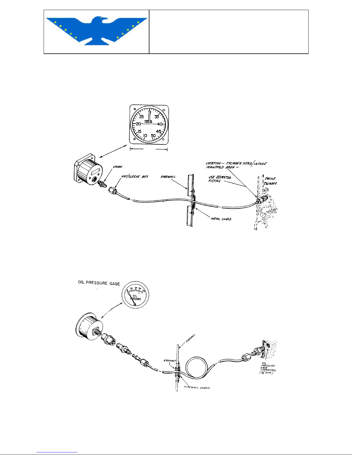
MAINTENANCE MANUAL
STORM Century S-LSA
STORM Century S-LSA STORMAIRCRAFT
8.2 MAIN INSTRUMENTS
Fig.8-2 MANIFOLD PRESSURE GAUGE (OPTION)
STA - P/N 10-25145
Fig.8-3 OIL PRESSURE GAUGE
STA - P/N 956 520
Page 97
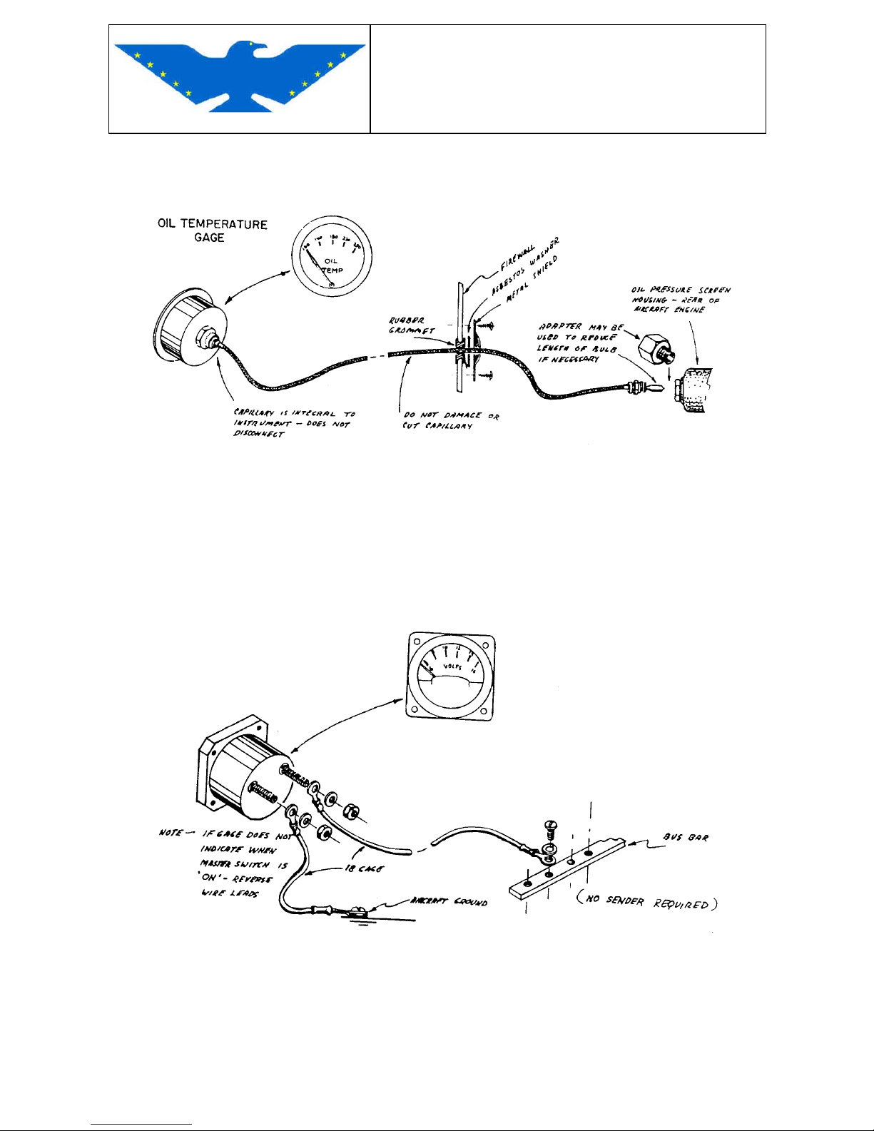
MAINTENANCE MANUAL
STORM Century S-LSA
STORM Century S-LSA STORMAIRCRAFT
Fig.8-4 OIL TEMPERATURE GAUGE
STA - 956 525
Fig.8-5 VOLTMETER
STA - 332.304/015/001 8-16 V.
Page 98
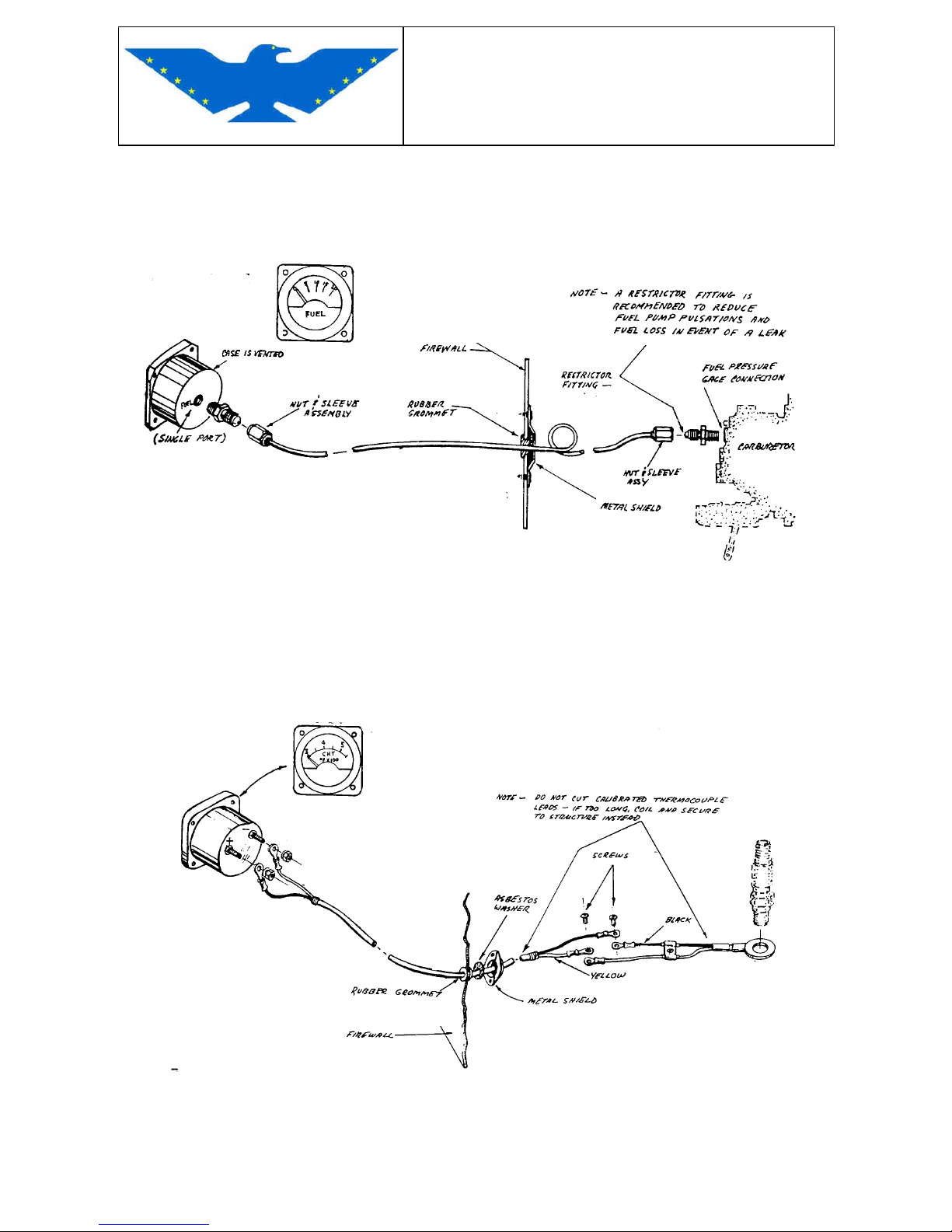
MAINTENANCE MANUAL
STORM Century S-LSA
STORM Century S-LSA STORMAIRCRAFT
Fig.8-6 FUEL GAUGE
STA - P/N 10-22201
Fig.8-7 CYLINDER HEAD TELETHERMOMETER
STA - P/N 956 525
Page 99
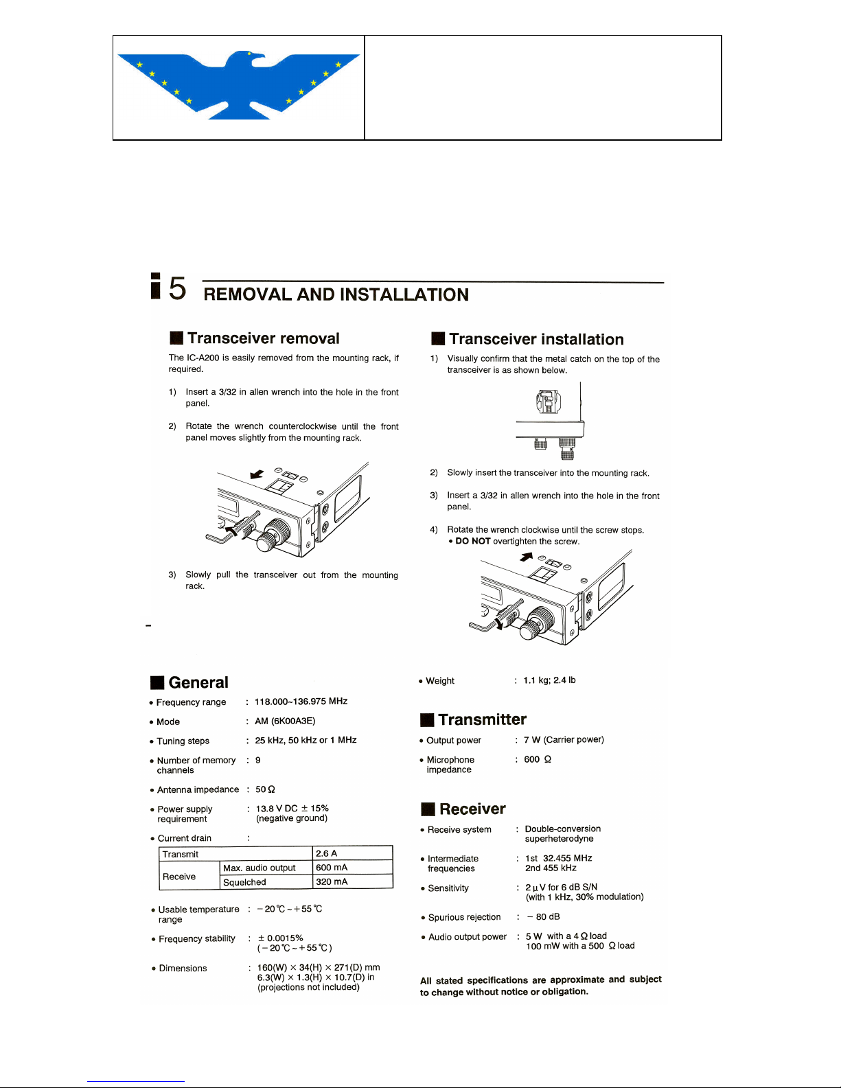
MAINTENANCE MANUAL
RALLY S-LSA
RALLY S-LSA STORM
AIRCRAFT
93
L AND INSTALLATION (from ICOM IC-A200
Installat
8.3 RADIO
ICOM IC-A200 DIO SET REMOVA
ion Manual)
RA
Page 100
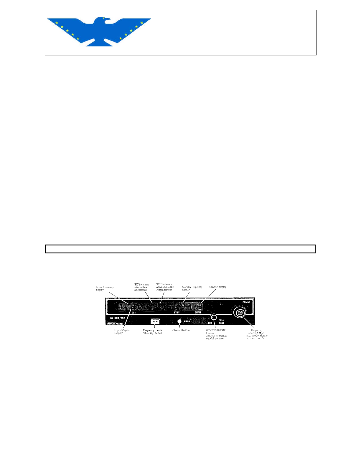
MAINTENANCE MANUAL
STORM Century S-LSA
STORM Century S-LSA STORMAIRCRAFT
BENDIX / KING KY97A (OPTION) TSO RADIO SET DESCRIPTION
In addition to ICOM IC-A200, the STORM LSA can be equipped with a "com" BENDIX / KING
KY97A TSO radio set, which allows to select an operating frequency and stand-by in a frequency
range from 118 MHz to 136.975 MHz (760 channels).- The radio set is in the lower central part of
the instrument panel. To remove radio set from panel, use the special setscrew wrench, 1/2 turn;
this will lock or unlock the radio set in its position on instrument panel.
SPECIFICATIONS
KY 97A : Operated at 14 volts
TSO compliance: Transmitter: TSO C37c,Class 3 or 4
Receiver : TSO C38c,Class A&C
Dimensions: Height : 1.35 inches ( 3,43 cm)
Width : 6.312 inches (16,032 cm)
Depth : 10.776 inches (27,37 cm)
Weight: 2.8 lbs (1,27 Kg)
Temperature Range: - 20° C to + 55° C with short time operation at + 70° C
Frequency Range: 118.0 to 136.975 MHz in 25 KHZ increments
Power output: 5 Watt minimun
Modulations: 70% modulation with 98% limiting. Less than 15% distortion at 70%
modulation.
Duty Cycle: 1 minute on, 4 minutes off.
Receiver Sensitivity: 2uV (hard) or less for 6dB s+N/N with 1 KHz tone modulated 30%.
Antenna Broad Band p/n av-529
Fig.8-8 KY97A TSO radio set
 Loading...