

Page 1

Rührgerät Quick Mixx 25
Schwergutrührer Quick Mixx 50
D
Roerapparaat Quick Mixx 25
Roerder voor zware materialen Quick Mixx 50
Mélangeur Quick Mixx 25
Mélangeur à marchandises lourdes Quick Mixx 50
Agitatore Quick Mixx 25
Miscelatore per materiale pesante Quick Mixx 50
Mixer Quick Mixx 25
Heavy goods mixer Quick Mixx 50
Míchadlo Quick Mixx 25
Míchadlo na těžký materiál Quick Mix 50
Miešačka Quick Mixx 25
Miešačka ťažkého materiálu Quick Mixx 50
NL
F
I
GB
CZ
SK
Page 2

2
Page 3
Vielen Dank
für Ihr Vertrauen zu STORCH. Mit dem Kauf haben
Sie sich für ein Qualitäts-Produkt entschieden.
Haben Sie trotzdem Anregungen zur Verbesserung
oder aber vielleicht einmal ein Problem, so freuen wir
uns sehr, von Ihnen zu hören. Bitte sprechen Sie mit
Ihrem Außendienst-Mitarbeiter oder in dringenden
Fällen auch mit uns direkt.
Mit freundlichen Grüßen
STORCH Service Abteilung
Tel. 02 02 . 49 20 - 112
Fax 02 02 . 49 20 - 244
kostenlose Service-Hotline: 08 00. 7 86 72 47
kostenlose Bestell-Hotline: 08 00. 7 86 72 44
kostenloses Bestell-Fax: 08 00. 7 86 72 43
(nur innerhalb Deutschlands)
Inhalt Seite
Technische Daten 3
Lieferumfang 3
Geräteübersicht 4
Sicherheitshinweise 4
Elektrischer Anschluss 5
Grundlegende Funktionen 7
Grundlegende Bedienung 7
Reinigung des Rührwerkes 8
Stückliste Quick Mixx 25 9
Stückliste Quick Mixx 50 10
Technische Daten
Quick Mixx 25 Quick Mixx 50
Spannung 230V / 50Hz 230V / 50Hz
Eingangsleis-
tung
Ausgangsleis-
tung (N-m)
Anzahl Gänge 1 2
Leerlaufdreh-
zahl
Schutzart Klasse 2 Klasse 2
Kupplungsge-
winde
Rührstab max.
Durchmesser
Elektronische
Drehzahlsteuerung
Gewicht 3,6 kg 4,1 kg
Lieferumfang
Rührgerät, Montagschlüssel, Bedienungsanleitung
1100 Watt 1300 Watt
13,5 14,7
250~700 1. Gang
150~400
2. Gang
250~700
M14 M14
120 mm 140 mm
Ja Ja
3
Page 4

Geräteübersicht
2
1
Sicherheitshinweise
Auf dieses Symbol achten, welches auf
wichtige Sicherheitshinweise hindeutet.
Es bedeutet ACHTUNG!!!
4
Achtung!
3
Achtung!
weise, Gefahr- und Warnhinweise genau. Das Gerät
nur für den vorgesehenen Einsatzzweck verwenden.
5
Die Nichtbeachtung kann zu Schäden am Gerät oder
sogar zu körperlichen Verletzungen führen. Keine
baulichen Veränderungen am Gerät vornehmen!
Das Gerät vor jedem Gebrauch kontrollieren.
• Bewegliche Teile auf fachgerechten An schluss prüfen.
• Vor dem einstecken des Netzsteckers den
Ein / Aus-Schalter auf Aus schalten
• Auf beschädigte Kabel kontrollieren.
• Auf gebrochene Teile kontrollieren.
Es geht um Ihre Sicherheit.
Bitte alle Bedienungs- und Sicherheitshinweise lesen und beachten. Vor Inbetriebnahem des Gerätes lesen Sie bitte
erst die komplette Bedienungsanleitung
um einen sicheren Betrieb zu gewähr-
leisten. Beachten Sie alle Sicherheitshin-
1 Gangwahlschalter (bei Quick Mixx 50)
2 Ein / Ausschalter mit Arretierung
3 Werkzeugaufnahme
4 Drehzahlregulierung
5 Rührwendel (optional)
o. Abb. Montageschlüssel (mitgeliefert)
Das Gerät mit Sorgfalt pfl egen. Das Werkzeug sau-
ber halten, um größtmögliche Sicherheit und optimale Leistung zu gewährleisten.
• Das Gerät niemals in der Nähe von
brennbaren Flüssigkeiten, Dämpfen
oder Gasen verwenden.
• Vor Feuchtigkeit und Regen schüt-
Achtung!
Während des Betriebes
• Bei dem Anmischen von Trockenware kann
Staub entstehen. Zum Schutze der Gesund
heit muss der Arbeitsbereich gut gelüftet
werden und Stets eine Atemschutzmaske
und Schutzbrille tragen. Beachten Sie die Si cherheitshinweise des Materialherstellers.
• Keine weite Kleidung, Halstücher oder
Schmuck (Ringe, Armbanduhren) tragen.
Diese könnten von drehenden Teilen erfasst
werden. Schutzhandschuhe tragen.
zen.
4
Page 5
Bei laufender Maschine
Diese Sicherheitshinweise aufbewahren
Nicht zulassen, dass Routine (in Folge
des häufi gen Gebrauchs des Rührwerks)
zu Flüchtigkeitsfehlern führt. Unachtsamkeit für Bruchteile von Sekunden
Achtung!
• Falls das Werkzeug ungewohnte Geräusche
macht oder stark vibriert, die Arbeit sofort
abbrechen. Das Werkzeug ausschalten.
Den Netzstecker ziehen. Nicht in Betrieb
nehmen, bevor der Fehler gefunden und
behoben wurde.
• Alle Besucher, Zuschauer und Kinder vom
Werkzeug und Arbeitsplatz fernhalten.
Vor dem Abstellen des Werkzeugs: Das laufende
Werkzeug niemals unbeaufsichtigt lassen
• Das Gerät ausschalten,
• Warten, bis alle beweglichen Teile zum Still stand gekommen sind,
• Den Netzstecker ziehen.
Durch den Betrieb von Elektrowerkzeugen können
Fremdkörper in Ihre Augen geschleudert werden,
wodurch es zu ernsthaften Augenverletzungen kommen kann. Vor der Inbetriebnahme des Werkzeugs
immer Schutzbrille mit Seitenschutz und bei Bedarf
einen Vollgesichtsschutz anlegen. Wir empfehlen
eine Vollsichtbrille für das Tragen über Korrektionsbrillen oder Standard-Sicherheitsbrillen mit Seitenschutz.
Achtung!
unzugänglichen Ort aufbewahren.
kann schon schwere Verletzungen zur
Folge haben.
Die Werkstatt kindersicher gestalten
• Die Werkstatt abschließen
• Die Hauptschalter ausschalten
• Das Werkzeug an einem für Kinder und andere für den Gebrauch des
Werkzeugs nicht qualifi zierte Personen
Motorenbezogene und elektrische Anforderungen
ACHTUNG: Einen fachgerechten Stromkreisschutz verwenden, um das Risiko
bezüglich elektrischer Gefahren, Brandgefahr oder Beschädigung des Werk-
Achtung!
angegebenen Spannung ausgelegt. Das Werkzeug an
eine Netzleitung mit der entsprechenden Spannung
und einem 16 Ampere-Abzweigleitung anschließen. Eine träge 16 Ampere-Sicherung oder einen
Schutzschalter verwenden. Ein verschlissenes, abgeschnittenes oder in irgendeiner Form beschädigtes
Netzkabel ist umgehend zu ersetzen, um die Stromschlag- oder Brandgefahr zu reduzieren.
Elektrischer Anschluss
Hinweis
Steckdose passt, ist eine passende Steckdose von einem qualifi zierten Elektriker zu installieren.
Ein unsachgemäßer Anschluss des Schutzleiters kann
zu einem Stromschlag führen. Bei der Ader mit einer
grünen Isolation mit oder ohne gelben Streifen handelt es sich um den Schutzleiter. Falls die Reparatur
oder der Ersatz des Steckers oder des Netzkabels
erforderlich ist, darf der Schutzleiter nicht an einen
stromführenden Anschluss angeschlossen werden.
Falls das Netzkabel verschlissen, abgeschnitten oder
auf irgendeine Weise beschädigt ist, ist es umgehend
von einer qualifi zierten Elektrofachkraft zu ersetzen.
Falls die Anweisungen bezüglich Erdung nicht vollständig verstanden wurden oder Zweifel über die
ordnungsgemäße Erdung des Werkzeugs bestehen,
ist das Werkzeug durch eine qualifi zierten Elektro-
fachkraft oder STORCH-Service-Station zu kontrollieren.
zeugs zu reduzieren. Das Werkzeug ist
fabrikseits für den Betrieb mit der oben
Der Stecker muss an eine passende,
entsprechend den örtlichen Gesetzen
und Bestimmungen ordnungsgemäß
montierte und geerdete Steckdose angeschlossen werden. Keine Veränderungen am gelieferten Stecker vornehmen.
Falls der gelieferte Stecker nicht in die
Achtung!
5
Darauf achten, dass während des Einsteckens oder Ziehens des Netzsteckers
kein Fingerkontakt mit den Anschlüssen des Netzsteckers besteht, um die
Verletzungs- oder Lebensgefahr durch
Stromschlag zu vermeiden.
Page 6
Bei unsachgemäßer Erdung kann dieses
Werkzeug einen Stromschlag auslösen,
besonders bei Verwendung in feuchten
Bereichen, in der Nähe von Rohrleitungen oder im Freien. Im Falle eines
Achtung!
kontakt mit dem Rührer.
Motorsicherheit
WICHTIG: Zur Vermeidung von Motorschäden muss
dieser Motor häufi g ausgeblasen oder ausgesaugt
werden, damit regelmäßig die normale Motorbelüftung nicht durch Staub beeinträchtigt wird.
Das Werkzeug an ein Stromnetz mit der dem 1.
Modell entsprechenden Spannung und einer 16
Ampere-Abzweigleitung mit einer trägen 16 Ampere-Sicherung oder einem Schutzschalter anschließen.
Wenn der Motor nicht startet, den Schalter um-2.
gehend in die "OFF"-Position bringen und den
Netzstecker des Werkzeugs ziehen.
Sollte der Motor während des Mischens plötzlich 3.
blockieren, den Einschalter loslassen und den
Netzstecker des Werkzeugs ziehen. Der Motor
kann nun wieder gestartet werden.
Aus nachstehenden Gründen können Sicherungen 4.
häufi g auslösen oder Schutzschalter abschalten
a) Motor ist überlastet - Überlastung
kann auftreten, wenn zu schnell nachgefüllt oder das Werkzeug innerhalb kurzer Zeit
zu häufi g gestartet und angehalten wird.
b) Die Netzspannung darf die Nennspannung
laut Typenschild nicht um mehr als 10% überoder unterschreiten. Bei schweren Lasten muss
die am Motoranschluss anliegende Spannung der
für das Modell angegebenen Spannung genau
entsprechen.
Die meisten Motorschäden können auf lose oder 5.
fehlerhafte Verbindungen, Überlast und zu niedriger Spannung (beispielsweise zu kleiner Aderquerschnitt im Netz) oder übermäßig lange Adern
im Versorgungsstromkreis zurückgeführt werden.
Wenn der Motor nicht einwandfrei läuft, Immer
die Verbindungen, die Last und den Versorgungsstromkreis prüfen. Der Adernquerschnitt sollte
nicht weniger als 2,5mm² betragen.
Stromschlags entstehen möglicherweise Sekundärgefahren, z.B. durch Hand-
Auspacken und Kontrollieren des Lieferumfangs
Auspacken
Zur Reduzierung der Verletzungsgefahr durch unvermutetes Anlaufen oder
Stromschlag während des Auspackens
und der Montage den Netzstecker nicht
Achtung!
am Gerät grundsätzlich vom Netz getrennt bleiben.
Das Gerät wird komplett in einem Karton geliefert.
Das Werkzeug und alle losen Teile aus dem Kar-•
ton entnehmen.
Alle Teile auf einer sicheren, feststehenden Ar-•
beitsfl äche anordnen und das Werkzeug einer
sorgfältigen Sichtprüfung unterziehen.
Hinweis
Stückliste. Mit Hilfe dieser Liste die Teilenummer
des fehlenden Teils ermitteln.
Achtung!
an eine Steckdose anschließen. Das
Netzkabel muss während der Arbeiten
Vor Beginn der Montage Teile auf Vollständigkeit prüfen. Falls ein Teil fehlen
sollte, das Werkzeug nicht montieren.
Das Verpackungsmaterial auf fehlende
Teile kontrollieren. Am Ende dieser Anleitung befi ndet sich eine vollständige
Falls irgendwelche Teile fehlen, darf
das Elektrorührwerk nicht in Betrieb genommen werden, bis die fehlenden Teile ersetzt sind. Andernfalls kann es zu
schweren Verletzungen kommen.
6
Page 7
Grundlegende Funktionen
Ein / Ausschalter
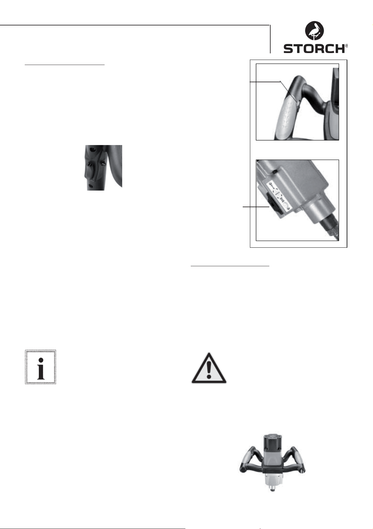
Ein-/Ausschalter - Zum Starten des Werkzeugs den
Einschalter drücken. Zum Ausschalten des Motors
den Einschalter loslassen. Dieses Werkzeug ist mit
einem Feststellknopf ausgestattet. Für Dauerbetrieb
den Einschalter betätigen und den Feststellknopf
drücken. Zum Ausschalten den Einschalter erneut
betätigen und dann loslassen.
Einstellen der Drehzahl
Für die beste Mischleistung bei einem bestimmten Mischgut kann die Drehzahl durch Drehen des
Stellrades mit dem Daumen elektronisch eingestellt
werden. Abb.1.
Gangwechsel
Drehzahlregulierung
Abb. 1
Gangwahlschalte
(nur Quick Mixx 50)
Abb. 2
Das Rührwerk Quick Mixx 50 ist mit einem Gangwahlschalter am Getriebegehäuse ausgestattet.
Für hochviskoses Mischgut die niedrige Drehzahl
wählen. Vor dem Einstellen eines Drehzahlbereichs
das Werkzeug ausschalten. Den Gangwählschalter
gegen die Federspannung eindrücken und zur Auswahl des gewünschten Drehzahlbereichs nach oben
bzw. nach unten schieben. Darauf achten, dass der
Gangwahlschalter richtig einrastet. Leichtes Drehen
der Spindel von Hand erleichtert das vollständige
Einkuppeln des Gangs. Abb.2
Vor dem Gangwechsel das Werkzeug
bitte ausschalten (OFF).
Hinweis
Grundlegende Bedienung
Einsatzgebiete
Zur effi zienten Kontrolle dieses Werkzeugs ist eine
zweihändige Bedienung für maximalen Schutz und
Standfestigkeit beim Anlauf- und Betriebsdrehmoment erforderlich. Um den Verlust der Kontrolle und
damit eventuell einhergehende Verletzungen zu vermeiden, das Gerät fachgerecht und sicher mit beiden
Händen halten. Zum Schutz vor Augenverletzungen
eine Schutzbrille tragen.
Das Netzkabel hinter dem Bediener
und vom Arbeitsbereich fernhalten, um
zu verhindern, dass sich das Kabel mit
dem Rührer verwickelt.
Achtung!
Griffe
Die Softgriffe des Rührwerks sind für optimale Griffi gkeit ausgelegt. Sie ermöglichen dem Bediener
auch bei längeren Einsatzzeiten einen ermüdungfreien Betrieb.
7
Page 8
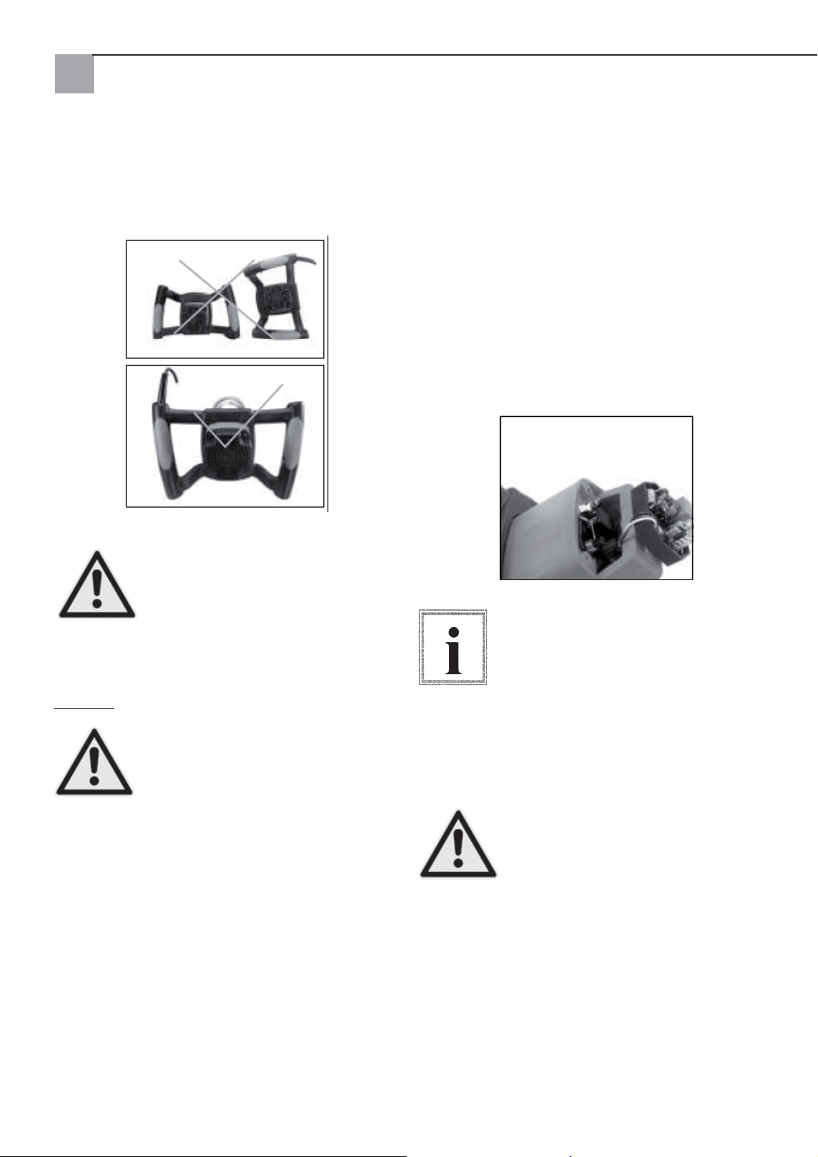
Griffposition beim Ablegen
Beim Ablegen des Elektrorührwerks bitte vorsichtig
vorgehen. Auf die richtige Position der Griffe beim
Ablegen achten.
Ersetzen der Kohlebürsten
Beide Kohlebürsten bei Abnutzung auf 7 mm Länge
ersetzen. Um die Kohlebürsten zu prüfen oder zu ersetzen, zunächst den Netzstecker des Gerätes ziehen.
Das Motorgehäuse durch Lösen der vier Schrauben
aufschrauben. Die Kohlebürstenfedern zurückziehen,
um die Spannung zu lösen. Die Schraube lösen, welche die Kohlebürstenführung hält. Die Kohlebürste
herausziehen.
Den Vorgang auf der anderen Seite wiederholen. Bei
der Montage in umgekehrter Reihenfolge vorgehen.
Die Laschen an der Metallseite der Bürsteneinheit
kommen in die gleiche Öffnung, in welche auch die
Kohleteile passen.
Das unsachgemäße Ablegen des Werkzeugs auf dem Boden (z.B. mit dem
Kabel nach unten) kann zur Beschädigung des Netzkabels und damit zur
Achtung!
Wartung
Achtung!
weglichen Teilen angesammelten Staub entfernen.
Darauf achten, dass das Werkzeug ordnungsgemäß
arbeitet. Schrauben und Bolzen regelmäßig auf festen Sitz prüfen.
Reinigung des Rührwerkes
Regelmäßig nach jeweils 50 Betriebsstunden alle
Lüftungsschlitze mit trockener Druckluft ausblasen.
Regelmäßig alle Kunststoffteile sind mit einem weichen, feuchten Tuch reinigen. Kunststoffteile NIEMALS mit Lösungsmitteln reinigen.
Beim Arbeiten mit Druckluft eine Schutzbrille tragen.
Nach jeweils 200 Betriebsstunden ist das Schmiermittel im Getriebe bei einer qualifi zierten STORCH-
Service-Station zu ersetzen.
Erhöhung der Stromschlaggefahr sowie
des Risikos von Beschädigungen am
Werkzeug führen.
Vor der Gerätewartung den Netzstecker
ziehen, um das Risiko von Verletzungen
infolge von unerwartetem Anlauf oder
Stromschlag zu reduzieren.
Das Werkzeug sauber halten. Auf be-
Zum Einsetzen derselben Bürsten zunächst sicherstellen, dass die Bürsten
genauso eingesetzt werden, wie sie entnommen wurden. Andernfalls kann in
Folge einer Einlaufperiode die Motorleis-
Hinweis
destens einmal im Jahr eine vollständige Reinigung
und Abschmierung des Gerätes bei einem autorisierten STORCH Kundendienstzentrum zu veranlassen.
Achtung!
tung reduziert und der Bürstenverschleiß
erhöht werden. Es wird empfohlen, min-
Um Sicherheit und Verlässlichkeit zu
gewährleisten, sollten alle Reparaturen
mit Ausnahme der von außen zugänglichen Kohlebürsten in einem autorisierten STORCH Kundendienstzentrum
vorgenommen werden.
8
Page 9
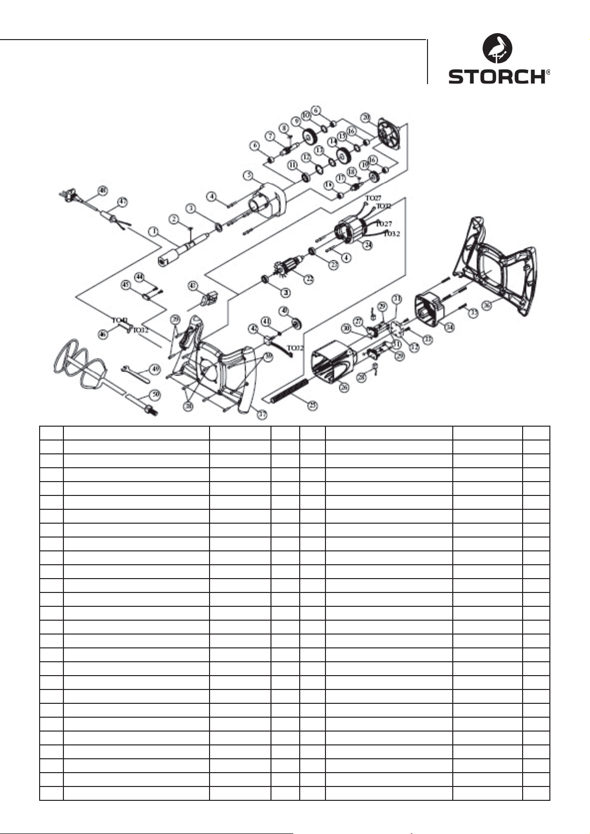
Stückliste Quick Mixx 25
Nr. Bezeichnung Stk. Nr. Bezeichnung Stk.
1 SPINDEL M14xP2.0 1 27 KOHLEBÜRSTENHALTER 2
2 FEDERKEIL 5x5x12 1 28 KOHLEBÜRSTE 2
3 DICHTUNG 22x32x7 1 29 SCHRAUBE M4x12 4
4 SCHRAUBE INKL. FEDERSCHEIBE M5x60 6 30 SECHSKANTMUTTER M4 2
5 GETRIEBEGEHÄUSE 1 1 31 FEDER 2
6 NADELLAGER HK1010 2 32 SENSOR MIT EMV 230V 1
7 RITZELWELLE 10T-080 1 33 SCHRAUBE M4x25 2
8 FEDERKEIL 5x5x10 1 34 MOTORABDECKUNG 1
9 VORGELEGERAD 30T 1 35 SCHRAUBE M5x20 4
10 SICHERUNGSRING S-12 1 36 HANDGRIFF (OBEN) 1
11 LAGER 6003ZZ 1 37 HANDGRIFF (UNTEN) 1
12 SICHERUNGSRING R-35 1 38 SCHRAUBE M4X20
13 SICHERUNGSRING S-17 1 39 SCHRAUBE M4X25 4
14 ZAHNRAD 34T 1 40 DREHZAHLEINSTELLRAD 1
15 SICHERUNGSRING S-15 1 41 SECHSKANTMUTTER 1/4“X34 1
16 NADELLAGER HK0810 3 42 ELEKTRONISCHE DREHZAHL
17 RITZELWELLE 14T 1 43 SCHALTER 8301 230V 1
18 FEDERKEIL 4X4X8 1 44 SCHRAUBE M4X14 2
19 VORGELEGERAD 37T 1 45 KABELSCHELLE 1
20 GETRIEBEABDECKUNG 1 46 KABEL 16AWG 2
21 LAGER 609 2RS 1 47 KABELWEHRUNG 1
22 ANKER 230V 1 48 NETZKABEL 230V 1
23 LAGER 608ZZ 1 49 SCHRAUBENSCHLÜSSEL M22 1
24 STATOR 230V 1 50 WENDELRÜHRER 1
25 KABELSCHUTZROHR M8 1 51 SCHRAUBE M4x10 2
26 MOTORGEHÄUSE 1
9
EINSTEL.B100K 1
Page 10

Stückliste Quick Mixx 50
Nr. Bezeichnung St. Nr. Bezeichnung St.
1 SPINDEL M14xP2.0 1 28 KABELSCHUTZROHR M8 1
2 FEDERKEIL 5x5x12 1 29 MOTORGEHÄUSE 1
3 DICHTUNG 2x32x7 1 30 KOHLEBÜRSTENHALTER 2
4 SCHRAUBE INKL. FEDERSCHEIBE M5x60 6 31 KOHLEBÜRSTE 2
5 GETRIEBEGEHÄUSE 1 32 SCHRAUBE M4X12 4
6 SCHLITZSCHRAUBE 1 33 SECHSKANTMUTTER M4 2
7 GANGWAHLSCHIEBESCHALTER 1 34 FEDER 2
8 FEDER Ø6x0.6x4 1 35 SENSOR MIT EMV 230V 1
9 SCHALTGABEL 1 36 SCHRAUBE M4x25 2
10 NADELLAGER HK1010 3 37 MOTORGEHÄUSEABDECKUNG 1
11 RITZELWELLE 10T-130 1 38 SCHRAUBE M5x20 4
12 FEDERKEIL 5x5x45 1 39 HANDGRIFF (OBEN) 1
13 VORGELEGERAD 30T&34T 1 40 HANDGRIFF (UNTEN) 1
14 LAGER 6003ZZ 1 41 SCHRAUBE M4x20 6
15 SICHERUNGSRING R-35 1 42 SCHRAUBE M4x25 4
16 SICHERUNGSRING S-17 1 43 DREHZAHLEINSTELLRAD 1
17 ZAHNRAD 34T 1 44 SECHSKANTMUTTER 1/4“x34 1
18 SICHERUNGSRING S-15 1 45 ELEKTRONISCHER DREHZAHL-
19 NADELLAGER HK0810 2 46 SCHALTER 8301 1
20 RITZELWELLE 14T&10T 1 47 SCHRAUBE M4x14 2
21 FEDERKEIL 4x4x8 1 48 KABELSCHELLE 1
22 VORGELEGERAD 37T 1 49 KABEL 16AWG 2
23 GETRIEBEABDECKUNG 1 50 KABELBEWEHRUNG 1
24 LAGER 609 2RS 1 51 NETZKABEL 230V 1
25 ANKER 230V 1 52 SCHRAUBENSCHLÜSSEL M22 1
26 LAGER 608ZZ 1 1 53 WENDELRÜHRER 1
27 STATOR 230V 1 54 SCHRAUBE M4x10 2
10
VERSTELLER
B100K 1
Page 11

EG-Konformitätserklärung
Wir erklären in alleiniger Verantwortung, dass das Produkt
Typ: Quick Mixx 25, Quick Mixx 50
auf welches sich in dieser Erklärung bezogen wird, mit den folgenden Normen und normativen Dokumenten übereinstimmt:
VDE 0740 - 1 : 2003-12
DIN EN 50144-1 : 2003-11
Entsprechend den Bestimmungen der Richtlinien 98/37/EWG, 73/23/EWG, 89/336/
EWG.
STORCH
Malerwerkzeuge & Profi geräte GmbH
Platz der Republik 6-8
42107 Wuppertal
Jörg Heinemann – Geschäftsführer
11
Page 12

NL
Hartelijk dank
voor uw vertrouwen in STORCH. Met deze aankoop
hebt u voor een kwaliteitsproduct gekozen.
Als u desondanks een tip voor verbeteringen hebt of
wellicht ooit een probleem ondervindt, dan horen wij
graag van u. Neem contact op met de medewerker
buitendienst of in dringende gevallen rechtstreeks
met ons.
Met vriendelijke groeten,
STORCH serviceafdeling
Tel. 0032 (0)475 75 07 99
Fax 0032 (0)9 229 31 99
Inhoud Pagina
Technische gegevens 12
Levering 12
Apparaatoverzicht 13
Veiligheidsrichtlijnen 13
Elektrische aansluiting 14
Basisfuncties 16
Basisbediening 16
Reiniging van het roermechanisme 17
Stuklijst Quick Mixx 25 18
Stuklijst Quick Mixx 50 19
Technische gegevens
Quick Mixx 25 Quick Mixx 50
Spanning 230V~, 50 Hz 230V~, 50 Hz
Ingangsvermogen 1100 Watt 1300 Watt
Uitgangsvermo-
gen (N-m)
Aantal versnel-
lingen
Stationair toeren-
tal
Beschermingsklasse
Koppelings
schroefdraad
Max. doorsnede
roerstaaf
Elektronische toerentalinstelling
Gewicht 3,6 kg 4,1 kg
13,5 14,7
12
250~700 1e versnelling
150~400
2e versnelling
250~700
Klasse 2 Klasse 2
M14 M14
120 mm 140 mm
Ja Ja
Levering
Roerapparaat, montagsleutel, gebruiksaanwijzing
12
Page 13

Apparaatoverzicht
4
2
3
1
5
1 Versnellingsschakelaar (bij Quick Mixx
50)
2 Aan/Uit-schakelaar met vergrendeling
3 Werktuigopname
4 Toerentalinstelling
5 Roerder (optioneel)
zonder
afb.
Montagesleutel (meegeleverd)
Veiligheidsrichtlijnen
Let op dit symbool, dit wijst op veiligheidsrichtlijnen. Het betekent LET OP!
Het gaat om uw veiligheid.
Pas op!
Lees alle bedienings- en veiligheidsricht-
lijnen en neem ze in acht. Lees voor ingebruikneming van het apparaat eerst
de complete gebruiksaanwijzing om veilige werking te garanderen. Neem alle
Pas op!
bruik het gereedschap alleen waarvoor het bestemd
is. Het niet in acht nemen kan tot schade aan het
apparaat of zelfs lichamelijke verwondingen leiden.
Geen bouwkundige veranderingen aan het apparaat
doorvoeren!
Controleer het apparaat telkens voor gebruik.
Controleer of bewegende onderdelen goed zijn •
aangesloten.
Zet voordat u de stekker in het stopcontact steekt •
de Aan/Uit-schakelaar op Uit.
Controleer of de kabel is beschadigd.•
Controleer of er geen breuken zijn in onderde-•
len.
Onderhoud het apparaat zorgvuldig. Houd het gereedschap schoon om optimale veiligheid en optimale prestaties te garanderen.
Pas op!
veiligheidsrichtlijnen, gevaarsrichtlijnen
en waarschuwingen precies in acht. Ge-
Gebruik het apparaat nooit in de bu •
urt van brandbare vloeistoffen, dam
pen of gassen.
Tegen vocht en regen beschermen.•
Tijdens het gebruik
Bij het mengen van droge materialen kan er stof •
ontstaan. Ter bescherming van de gezondheid
moet de werkplaats goed worden geventileerd en
dient u altijd een ademmasker en een veiligheidsbril te dragen. Neem de veiligheidsrichtlijnen van
de fabrikant van het materiaal in acht.
Draag geen losse kleding, halsdoeken of sieraden •
(ringen, horloges). Deze kunnen door draaiende
delen worden gegrepen. Draag beschermingshandschoenen
13
Page 14
Bij lopende machine
Bewaar deze veiligheidsrichtlijnen
Voorkom dat routine (door regelmatig
gebruik van de roerder) tot fouten leidt.
Een paar seconden onachtzaamheid kan
reeds zware verwondingen ten gevolg
Pas op!
Als het gereedschap ongewone geluiden maakt •
of sterk trilt, stop dan meteen met werken. Schakel het gereedschap uit. Trek de stekker uit het
stopcontact. Niet gebruiken totdat de fout is gevonden en verholpen.
Bezoekers, kijkers en kinderen uit de buurt van •
de werkplaats houden.
Voor het neerzetten van het apparaat: laat het lopende gereedschap nooit zonder toezicht achter
Schakel het apparaat uit,•
Wacht tot alle bewegende delen tot stilstand zijn •
gekomen,
Trek de stekker uit het stopcontact.•
Bij gebruik van elektrisch gereedschap kunnen er
deeltjes in uw ogen terechtkomen waardoor ernstige
oogverwondingen kunnen ontstaan. Voor ingebruikneming van het gereedschap dient u altijd een veiligheidsbril met zijbescherming en indien nodig een
volledige gezichtsbeschermer te plaatsen. Wij raden
een brillen voor dragen over correctiebrillen of standaardveiligheidsbrillen met zijbescherming aan.
Pas op!
hebben.
Zorg dat de werkplaats niet toegankelijk is voor kinderen
Sluit de werkplaats af•
Schakel de hoofdschakelaar uit•
Bewaar het gereedschap op een plaats •
die voor kinderen of niet-gekwalifi ceerde
personen niet toegankelijk is.
Motor- en elektrische eisen
LET OP: Gebruik een vakkundige stroomkringbeveiliging om het risico aangaande
elektrische gevaren, brandgevaar of beschadiging van het gereedschap te re-
Pas op!
aangegeven spanning. Sluit het gereedschap op een
netaansluiting met de dienstovereenkomstige spanning en een 16 Ampère-aftakleiding aan. Gebruik
een trage 16 Ampère-zekering of een beveiligingsschakelaar. Een versleten, afgesneden of in enige
vorm beschadigde stroomkabel dient direct te worden vervangen om het gevaar van elektrische schok
en brandgevaar te verkleinen.
Elektrische aansluiting
Tip
gekwalifi ceerde elektricien een passend stopcontact
te worden geïnstalleerd.
Ondeskundige aansluiting van de aardeleiding kan tot
een stroomschok leiden. De ader met groene isolement met of zonder gele streep is de aardekabel. Als
reparatie of vervanging van de stekker of de stroomkabel noodzakelijk is, mag de aardekabel niet op een
stroomvoerende aansluiting worden aangesloten.
Als de stroomkabel is versleten, afgesneden of op de
een of andere manier is beschadigd, dan dient deze
direct door een gekwalifi ceerde elektrovakman te
worden vervangen. Indien de instructies aangaande
de aarding u niet volledig duidelijk zijn of er twijfels
over het gebruik volgens de voorschriften bestaan,
dan moet het gereedschap door een gekwalifi ceerde
elektrovakman of een STORCH-servicestation worden gecontroleerd.
duceren. Het gereedschap is af fabriek
bestemd voor gebruik met de hierboven
De stekker moet worden aangesloten op een stopcontact dat conform de
plaatselijke wetgeving en bepalingen
is gemonteerd en geaard. Geen veranderingen doorvoeren aan de geleverde
stekker. Als de geleverde stekker niet in
het stopcontact past, dient er door een
14
Pas op!
Let erop dat u tijdens het insteken of
lostrekken van de stekker geen vingercontact met de aansluitingen van de
stekker maakt om verwondingen en levensgevaar door elektrische schokken te
voorkomen.
Page 15
Bij ondeskundige aarding kan dit gereedschap een elektrische schok veroorzaken, met name bij gebruik in vochtige ruimtes, in de buurt van buizen en
buiten. In geval van een elektrische
Pas op!
roerder.
Motorveiligheid
Pas op:Om motorschade te voorkomen, moet de mo-
tor regelmatig worden schoon geblazen of uitgezogen om te voorkomen dat de normale motorventilatie
door de stof wordt gehinderd.
Sluit het gereedschap op het lichtnet aan (dient 1.
overeen te komen met de spanningseisen van het
model) met een 16 Ampère-aftakleiding met een
trage 16 Ampère-zekering of een beveiligingsschakelaar aan.
Als de motor niet start, zet dan de schakelaar 2.
meteen in de "OFF"-positie en trek de stekker uit
het stopcontact.
Als de motor tijdens het mengen plotseling blok-3.
keert, laat dan de schakelaar los en trek de stekker uit het stopcontact. De motor kan nu weer
worden gestart.
Vanwege de volgende redenen kunnen zekerin-4.
gen regelmatig worden geactiveerd of kan de
beveiligingsschakelaar worden uitgeschakeld:
a) Motor is overbelast - Overbelasting
kan optreden wanneer er te snel wordt nagevuld of het gereedschap gedurende korte tijd vaak wordt gestart en gestopt.
b) De netspanning mag niet meer dan 10% naar
boven of beneden afwijken van de gegevens op
het typeplaatje. Bij zware lasten moet de spanning op de motoraansluiting precies overeenkomen met de voor het model aangegeven spanning.
De meeste motorschades zijn terug te voeren op 5.
losse of foutieve verbindingen, overbelasting en
te lage spanning (bijvoorbeeld te kleine aderdiameter in het net) of overmatig lange aderen in de
verzorgingsstroomkring. Wanneer de motor niet
feilloos loopt, dient u altijd de verbindingen, de
last en de verzorgingsstroomkring te controleren.
De aderdiameter mag niet minder dan 2,5mm²
bedragen.
schok ontstaan er mogelijk secundaire
gevaren, bijv. door handcontact met de
Uitpakken en de levering controleren
Uitpakken
Om kans op verwondingen door per ongeluk starten of elektrische schokken
te voorkomen, dient de stekker tijdens
het uitpakken en de montage niet in het
Pas op!
aan het apparaat altijd uit het stopcontact te zijn.
Het apparaat wordt compleet in een doos geleverd.
Haal het gereedschap en alle losse delen uit de •
doos.
Leg alle delen op een stevig en stabiel werkblad •
en controleer het gereedschap zorgvuldig.
Tip
hulp van deze lijst kunt u het onderdeelnummer van
het ontbrekende deel achterhalen.
Pas op!
stopcontact te worden gestoken. De
stroomkabel moet tijdens het werken
Controleer voor het begin van de montage
of alle delen aanwezig zijn. Als er een deel
ontbreekt, monteert dan het gereedschap
niet. Controleer of er zich ontbrekende
delen in het verpakkingsmateriaal bevinden. Aan het einde van deze handleiding
vindt u een volledige stuklijst. Met be-
Als er delen ontbreken, mag de roermachine niet in gebruik worden genomen
totdat de ontbrekende delen zijn vervangen. Anders kunnen er zware verwon-
dingen optreden.
15
Page 16
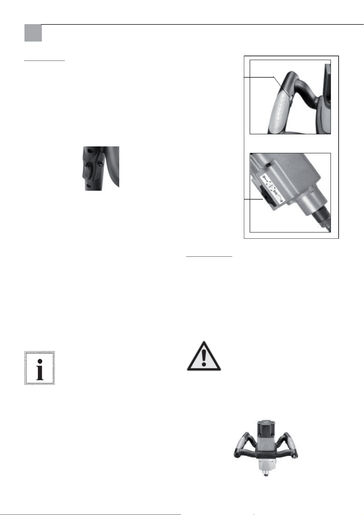
Basisfuncties
Aan/Uit-schakelaar
Aan/Uit-schakelaar - Druk op de Aan-schakelaar om
het gereedschap te starten. Laat de schakelaar weer
los om de motor uit te schakelen. Dit gereedschap
beschikt over een vergrendelingsknop. Voor langer
gebruik gebruikt u de Aan-schakelaar en drukt u op
de vergrendelingsknop. U schakelt het apparaat uit
door nogmaals kort op de Aan-schakelaar te drukken.
Het toerental instellen
Voor het best mengresultaat bij specifi eke meng-
materialen kan het toerental elektronisch worden
ingesteld door het instelwiel met de duim te draaien. Afb.1.
Toerentalinstelling
Afb. 1
Versnellingen kiezen
(alleen Quick Mixx
50)
Afb. 2
Van versnelling veranderen
De roerder Quick Mixx 50 beschikt over een versnellingsschakelaar op de behuizing. Voor hoogviskeus mengmateriaal kiest u het lage toerental. Voor
het instellen van een toerental schakelt u het gereedschap eerst uit. Druk de versnellingsschakelaar
tegen de veerspanning in en schuif de schakelaar
naar boven of beneden om het gewenste toerental
te kiezen. Let erop dat de versnellingsschakelaar
goed vast klikt. Draai de spindel desnoods een klein
eindje met de hand om de versnelling eenvoudig
volledig te laten koppelen. Afb.2
Voor het kiezen van een andere versnelling schakelt u het gereedschap uit
(OFF).
Tip
Basisbediening
Toepassingsgebieden
Voor effi ciënte controle van dit gereedschap is een
tweehandige bediening voor maximale bescherming
en grip bij het aanloop- en bedrijfsdraaimoment vereist. Om verlies van controle en eventuele hieruit
resulterende verwondingen te voorkomen, dient het
apparaat vakkundig en stevig met beide handen te
worden vastgehouden. Draag ter bescherming van de
ogen een veiligheidsbril.
Houd de stroomkabel achter de bediener en uit de buurt van de werkplek om
te voorkomen dat de kabel in de roerder verstrikt raakt.
Pas op!
Grepen
De softgrepen van de roerder zijn ontworpen voor optimale grip. Dankzij deze grepen kan de bediener het
apparaat lang gebruiken zonder moe te worden.
16
Page 17
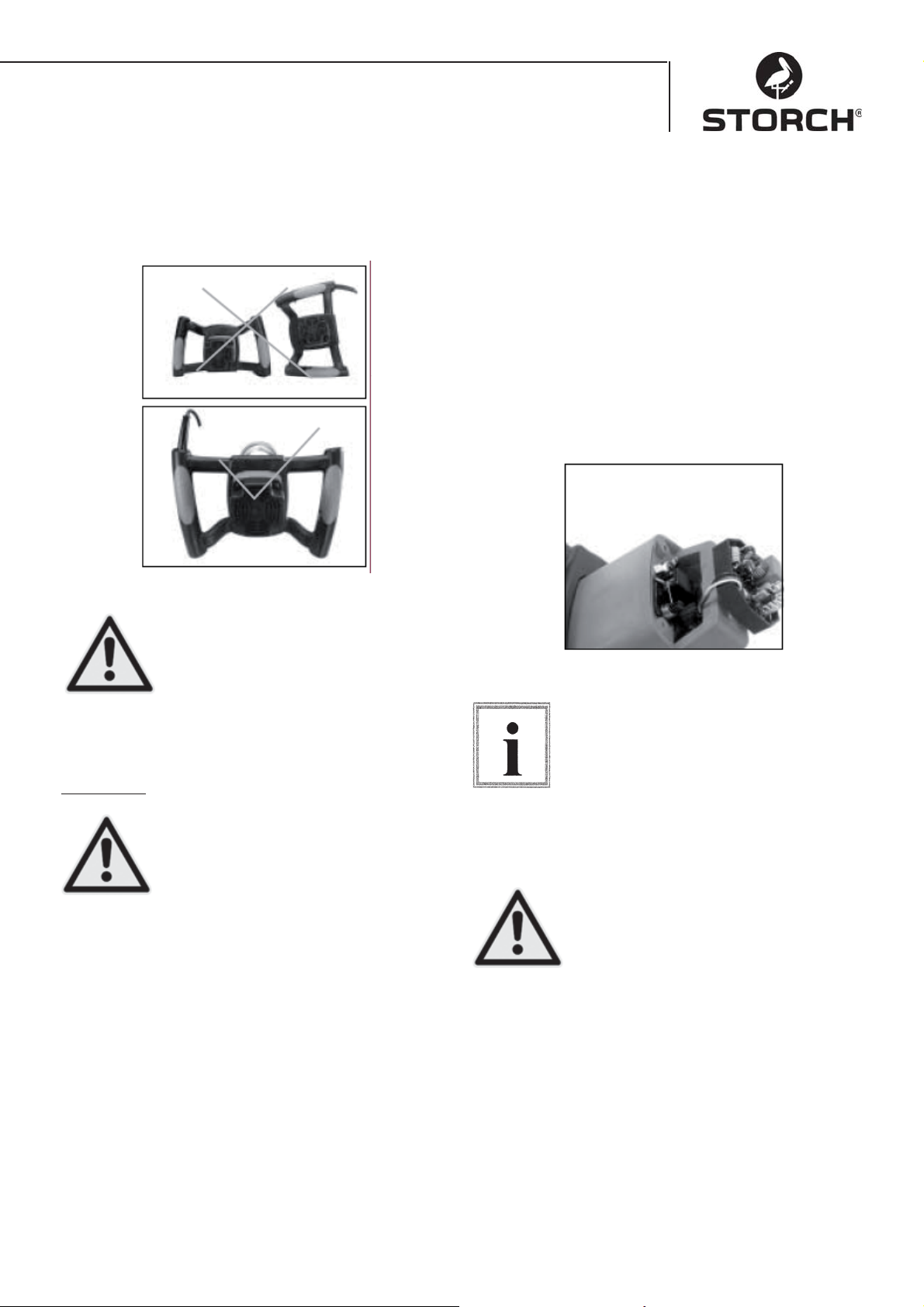
Greeppositie bij neerleggen
Ga voorzichtig te werk als u de roerder neerlegt. Let
hierbij op de juiste positie van de grepen.
Koolborstels vervangen
Vervang beide koolborstels als ze tot op 7 mm lengte
zijn versleten. Bij het controleren of vervangen van
de koolborstels trekt u allereerst de stekker van het
apparaat uit het stopcontact. Verwijder de motorbehuizing van de greep door de vier schroeven los
te draaien. Trek de veren van de koolborstels naar
achteren om de spanning weg te nemen. Draai de
schroef los waarmee de borstelhouder is bevestigd.
Trek de borstel eruit.
Herhaal deze procedure aan de andere kant. Ga bij de
montage in de omgekeerde volgorde te werk.
De lippen aan de metalen kant van de borsteleenheid
komen in dezelfde opening waarin ook de kooldelen
passen.
Het onoordeelkundig op de bodem leggen van het gereedschap (bijv. met de
kabel naar beneden) kan tot beschadiging van de stroomkabel en hiermee tot
Pas op!
Onderhoud
Pas op!
Houd het apparaat schoon. Verwijder stof op bewegende delen. Controleer of het apparaat correct
werkt. Controleer regelmatig of schroeven en bouten
goed vast zitten.
Reiniging van het roermechanisme
Blaas regelmatig na 50 bedrijfsuren alle ventilatiespleten met droge perslucht schoon. Alle kunststofdelen regelmatig met een zachte, vochtige doek
reinigen. Kunststofdelen NOOIT met oplosmiddelen
reinigen.
Bij werken met perslucht een beschermbril dragen.
Na 200 bedrijfsuren het smeermiddel in de aandrijving laten vervangen bij een gekwalifi ceerd servicep-
unt van STORCH.
vergroting van de kans op elektrische
schokken en het risico van beschadigingen aan het gereedschap leiden.
Trek voor het plegen van onderhoud aan
het apparaat de stekker uit het stopcontact om het risico van verwondingen
ten gevolge van onverwacht starten of
stroomschokken te voorkomen.
Bij het plaatsen van dezelfde borstel zorgt u er voor
dat de borstels precies zo worden geplaatst als ze zaten. Anders kunnen de
motorprestaties afnemen en de slijtage
van de borstels toenemen. Wij raden aan
het gereedschap ten minste 1 x per jaar
Tip
van STORCH.
Pas op!
volledig te laten reinigen en smeren bij
een geautoriseerd klantendienstcentrum
Om veiligheid en betrouwbaarheid te
waarborgen, dienen alle reparaties met
uitzondering van de van buiten toegankelijke koolborstels in een geautoriseerd STORCH klantendienstcentrum te
worden uitgevoerd.
17
Page 18
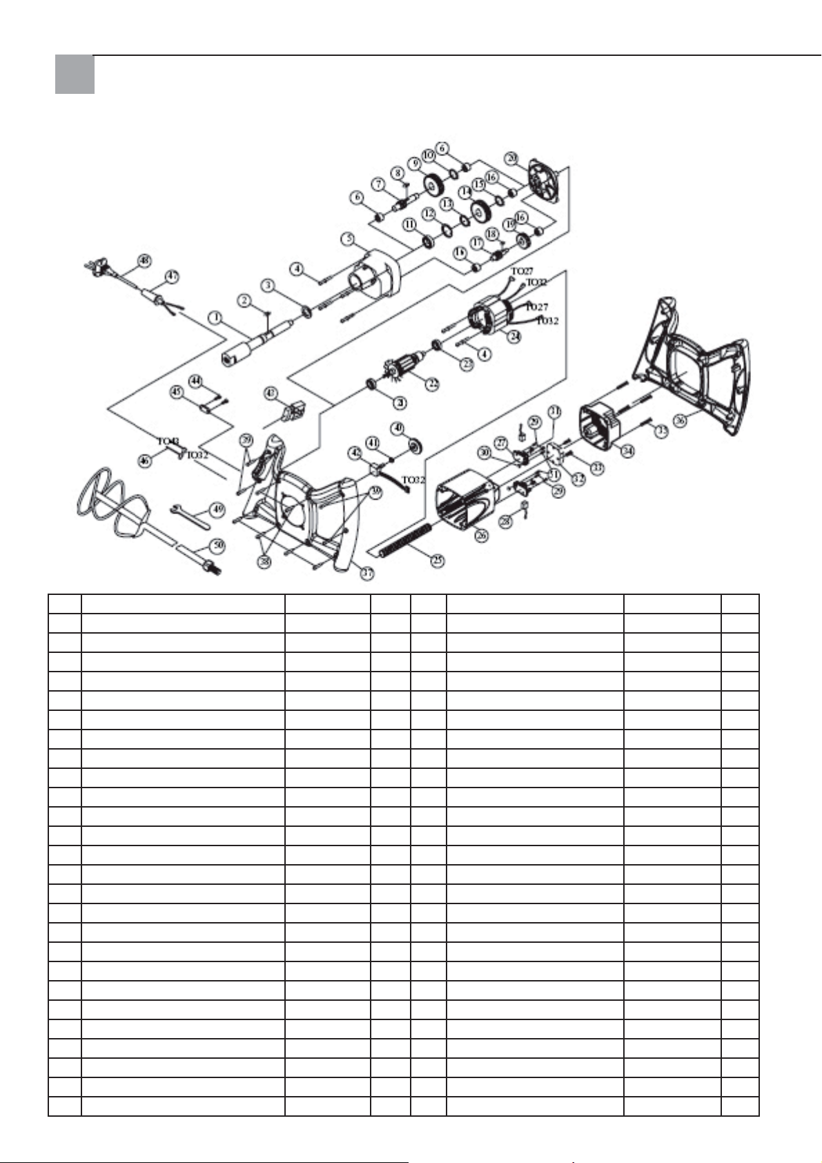
Stuklijst Quick Mixx 25
Nr. Omschrijving Stuk Nr. Omschrijving Stuk
1 SPINDEL M14xP2.0 1 27 KOOLBORSTELHOUDER 2
2 VEERWIG 5x5x12 1 28 KOOLBORSTEL 2
3 DICHTING 22x32x7 1 29 SCHROEF M4x12 4
4 SCHROEF INCL. VEERSCHIJF M5x60 6 30 ZESKANTMOER M4 2
5 AANDRIJFBEHUIZING 1 1 31 VEER 2
6 NAALDLAGER HK1010 2 32 SENSOR MET EMV 230V 1
7 RONDSELAS 10T-080 1 33 SCHROEF M4x25 2
8 VEERWIG 5x5x10 1 34 MOTORAFDEKKING 1
9 NEVENASWIEL 30T 1 35 SCHROEF M5x20 4
10 ZEKERINGSRING S-12 1 36 HANDGREEP (BOVEN) 1
11 LAGER 6003ZZ 1 37 HANDGREEP (ONDER) 1
12 ZEKERINGSRING R-35 1 38 SCHROEF M4X20
13 ZEKERINGSRING S-17 1 39 SCHROEF M4X25 4
14 TANDWIEL 34T 1 40 INSTELWIEL TOERENTAL 1
15 ZEKERINGSRING S-15 1 41 ZESKANTMOER 1/4“X34 1
16 NAALDLAGER HK0810 3 42 ELEKTRONISCH TOERENTAL
17 RONDSELAS 14T 1 43 SCHAKELAAR 8301 230V 1
18 VEERWIG 4X4X8 1 44 SCHROEF M4X14 2
19 NEVENASWIEL 37T 1 45 KABELBEVESTIGING 1
20 TRANSMISSIE-AFDEKKING 1 46 KABEL 16AWG 2
21 LAGER 609 2RS 1 47 KABELWEERSTAND 1
22 ANKER 230V 1 48 STROOMKABEL 230V 1
23 LAGER 608ZZ 1 49 SCHROEFSLEUTEL M22 1
24 STATOR 230V 1 50 SCHROEFROERDER 1
25 KABELBESCHERMINGSBUIS M8 1 51 SCHROEF M4x10 2
26 MOTORBEHUIZING 1
18
INSTEL.B100K 1
Page 19
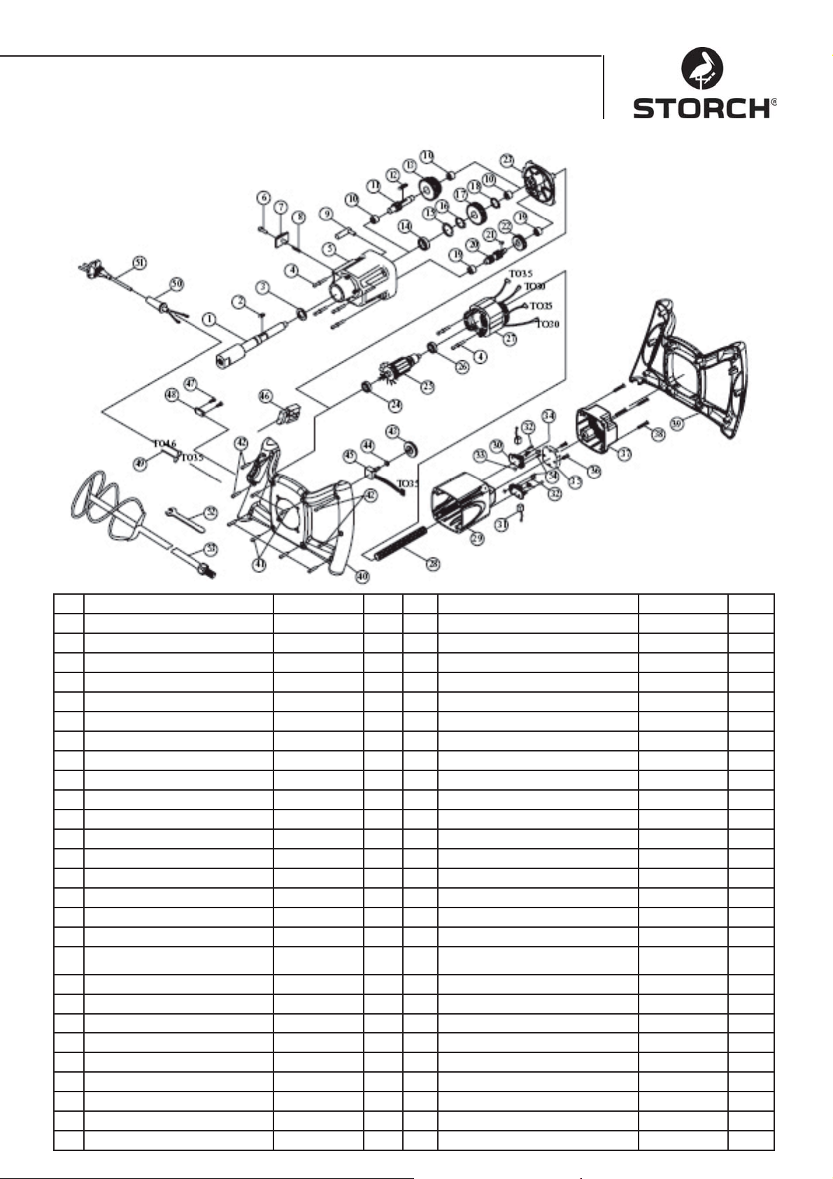
Stuklijst Quick Mixx 50
Nr. Omschrijving Ond. Nr. Omschrijving Ond.
1 SPINDEL M14xP2.0 1 28 KABELBESCHERMINGSBUIS M8 1
2 VEERWIG 5x5x12 1 29 MOTORBEHUIZING 1
3 DICHTING 2x32x7 1 30 KOOLBORSTELHOUDER 2
4 SCHROEF INCL. VEERSCHIJF M5x60 6 31 KOOLBORSTEL 2
5 AANDRIJFBEHUIZING 1 32 SCHROEF M4X12 4
6 PLATTE SCHROEF 1 33 ZESKANTMOER M4 2
7 VERSNELLINGSSCHAKELAAR 1 34 VEER 2
8 VEER Ø6x0.6x4 1 35 SENSOR MET EMV 230V 1
9 SCHAKELVORK 1 36 SCHROEF M4x25 2
10 NAALDLAGER HK1010 3 37 AFDEKKING MOTORBEHUIZING 1
11 RONDSELAS 10T-130 1 38 SCHROEF M5x20 4
12 VEERWIG 5x5x45 1 39 HANDGREEP (BOVEN) 1
13 NEVENASWIEL 30T&34T 1 40 HANDGREEP (ONDER) 1
14 LAGER 6003ZZ 1 41 SCHROEF M4x20 6
15 ZEKERINGSRING R-35 1 42 SCHROEF M4x25 4
16 ZEKERINGSRING S-17 1 43 INSTELWIEL TOERENTAL 1
17 TANDWIEL 34T 1 44 ZESKANTMOER 1/4“x34 1
18 ZEKERINGSRING S-15 1 45 ELEKTRONISCHE TOERENTAL-
19 NAALDLAGER HK0810 2 46 SCHAKELAAR 8301 1
20 RONDSELAS 14T&10T 1 47 SCHROEF M4x14 2
21 VEERWIG 4x4x8 1 48 KABELBEVESTIGING 1
22 NEVENASWIEL 37T 1 49 KABEL 16AWG 2
23 TRANSMISSIE-AFDEKKING 1 50 KABELVERSTERKING 1
24 LAGER 609 2RS 1 51 STROOMKABEL 230V 1
25 ANKER 230V 1 52 SCHROEFSLEUTEL M22 1
26 LAGER 608ZZ 1 1 53 SCHROEFROERDER 1
27 STATOR 230V 1 54 SCHROEF M4x10 2
VERSTELLER
19
B100K 1
Page 20

EG-conformiteitverklaring
Wij verklaren als enige verantwoordelijke dat het product
Type: Quick Mixx 25, Quick Mixx 50
waarop deze verklaring betrekking heeft, in overeenstemming is met de
volgende normen en normatieve documenten:
VDE 0740 - 1 : 2003-12
DIN EN 50144-1 : 2003-11
Voldoet aan de bepalingen van de richtlijnen 98/37/EWG, 73/23/EWG,
89/336/EWG.
STORCH
Malerwerkzeuge & Profi geräte GmbH
Platz der Republik 6-8
42107 Wuppertal
Jörg Heinemann – Directeur
20
Page 21
F
Nous vous remercions
de votre confi ance en STORCH. Avec cet achat vous
avez opté pour un produit de qualité.
Si malgré tout vous aviez des suggestions d'amélioration,
voire éventuellement un problème, n'hésitez pas à
nous en faire part. Dans ce cas, contactez votre représentant, ou directement notre service clients, s'il
s'agit d'un problème urgent.
Sincères salutations
Service clients STORCH
Tel. 0032 (0)475 75 07 99
Fax 0032 (0)9 229 31 99
Contenu Page
Caractéristiques techniques 21
Fourniture 21
Vue d'ensemble de l'appareil 22
Consignes de sécurité 22
Raccordement électrique 23
Fonctions de base 25
Maniement de base 25
Nettoyage du mélangeur 26
Nomenclature Quick Mixx 25 27
Nomenclature Quick Mixx 50 28
Caractéristiques techniques
Quick Mixx 25 Quick Mixx 50
Tension 230 V / 50 Hz 230 V / 50 Hz
Puissance à
l'entrée
Puissance de
sortie (N-m)
Nombre de rap-
ports
Régime de
ralenti
Type de protection
Filetage
d'accouplement
Diamètre max.
barre de mélange
Commande
électronique de
régime
Poids 3,6 kg 4,1 kg
Fourniture
Mélangeur, clé de montage, instructions de service
1100 Watt 1300 Watt
13,5 14,7
12
250~700 1er rapport
150~400
2ème rapport
250~700
Classe 2 Classe 2
M14 M14
120 mm 140 mm
Oui Oui
21
Page 22
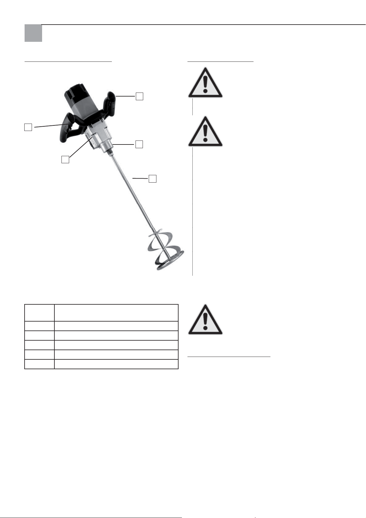
Vue d'ensemble de l'appareil
2
1
Consignes de sécurité
Veiller sur ce symbole qui indique des
consignes de sécurité importantes. Cela
signifi e ATTENTION !!!
4
Attention !
Il s'agit de votre sécurité.
Lire et respecter toutes les consignes de
sécurité et de maniement. Avant la mise
en service de l'appareil, lire tout d'abord
3
Attention !
les instructions de service complètes
pour garantir un fonctionnement sûr. Re-
specter à la lettre toutes les consignes de
sécurité, les avertissements et les mentions de danger. Utiliser uniquement l'appareil pour la destination
5
prévue. Tout non-respect peut entraîner des dommages de l'appareil, voire des blessures corporelles. Ne
pas modifi er l'appareil !
Contrôler l'appareil avant chaque utilisation.
Contrôler que les pièces mobiles sont correcte-•
ment raccordées.
Avant d'enfi cher la fi che secteur, mettre •
l'interrupteur marche/arrêt sur arrêt
Contrôler le câble endommagé.•
Contrôler les pièces cassées.•
1 Sélecteur de rapport (avec Quick Mixx
50)
2 Interrupteur marche/arrêt avec blocage
3 Réception d'outil
4 Régulation du régime
5 Hélice mélangeuse (en option)
sans ill. Clé de montage (jointe)
Entretenir l'appareil avec soin. La garder propre pour
garantir une sécurité maximale et un rendement optimal.
Ne jamais utiliser l'appareil à proxi-•
mité de liquides, de vapeurs ou de gaz
infl ammables.
Protéger de l'humidité et de la pluie.•
Attention !
Pendant le fonctionnement
Lors du mélange de matériaux secs, de la pous-•
sière peut être produite. La zone de travail doit
être bien ventilée pour la protection de la santé et
porter toujours un masque de protection respiratoire et des lunettes de protection. Respecter les
consignes de sécurité du fabricant du matériau.
Ne pas porter de vêtements amples, d'écharpes •
ou de bijoux (bagues, montres). Ceux-ci peuvent
être happés par des pièces mobiles. Porter des
gants de protection.
22
Page 23
Avec la machine en service
Conserver ces consignes de sécurité
Ne pas permettre que la routine entraî-
ne des erreurs d'inattention (à la suite
de l'utilisation fréquente du mélangeur).
Une inattention de quelques secondes
Attention !
seulement peut avoir pour conséquence
des blessures graves.
Si l'outil émet des bruits inhabituels ou vibre •
fortement, arrêter immédiatement le travail.
Mettre l'outil hors service. Débrancher la fi che
secteur. Ne pas le mettre en service avant que
l'erreur n'ait été trouvée et résolue.
Maintenir tous les visiteurs, spectateurs et en-•
fants à distance de l'outil et du poste de travail.
Avant de ranger l'outil : ne jamais l'appareil en
marche sans surveillance
Mettre l'appareil hors service,•
Attendre jusqu'à ce que toutes les pièces soient •
arrêtées.
Débrancher la fi che secteur.•
Le fonctionnement d'outils électriques peut projeter
des corps étrangers dans les yeux, ce qui peut provoquer des blessures graves aux yeux. Avant la mise
en service de l'outil, toujours porter des lunettes de
protection avec coque latérale et si nécessaire porter
une protection pour tout le visage. Nous recommandons des lunettes panoramiques pour le port de lunettes de vue ou des lunettes de protection standard
avec coque latérale.
Organiser l'atelier en prenant en compte la sécurité
des enfants
Raccorder l'atelier•
Couper le sectionneur général•
Conserver l'outil à un endroit inac-•
cessible pour les enfants et toute autre personne qui n'est pas qualifi ée pour
Attention !
l'utilisation de l'outil.
Exigences électriques et fondées sur le moteur
ATTENTION : utiliser un disjoncteur de
circuit électrique approprié pour réduire
le risque de danger électrique, d'incendie
ou d'endommagement de l'outil. L'outil
Attention !
est conçu en usine pour le fonctionne-
ment avec la tension indiquée ci-dessus.
Raccorder l'outil à un câble d'alimentation secteur
avec la tension correspondante et d'une conduite
de dérivation de 16 ampères. Utiliser un fusible de
16 ampère ou un disjoncteur-protecteur. Un câble
d'alimentation secteur usé, coupé ou endommagé de
quelque manière que ce soit doit être remplacé immédiatement pour réduire le risque de choc électrique
ou d'incendie.
Raccordement électrique
La fi che doit être branchée à une prise
mise à la terre adaptée et montée conformément aux lois et règlements locaux.
Ne pas modifi er les prises fournies. Si la
Remarque
fi che fournie ne rentre pas dans la prise,
faire installer une prise adaptée par un
électricien qualifi é.
Un branchement incorrect du conducteur de protection peut être la cause d'une électrocution. Le fi l
avec une isolation verte avec ou sans bandes jaunes
est le conducteur de protection. Si la réparation ou le
remplacement de la fi che ou du câble d'alimentation
secteur est nécessaire, le conducteur de protection
ne doit pas être raccordé à une prise sous tension.
Si le câble d'alimentation secteur est usé, coupé ou
endommagé de quelque manière que ce soit, il doit
être remplacé immédiatement par un électricien qualifi é. Si les instructions concernant la mise à la terre
ne sont bien comprises ou s'il y a un doute quant à la
mise à la terre correcte de l'outil, il faut faire contrôler l'outil par un électricien qualifi é ou une station de
service STORCH.
23
Attention !
Veiller que pendant l'enfi chage ou le
débranchement de la fi che secteur les
doigts ne soient absolument pas en contact avec les connexions de la prise pour
éviter tout risque de blessure ou de mort
par choc électrique.
Page 24
Si cet outil est mal relié à la terre, un
choc électrique peut se produire, en
particulier en cas d'utilisation dans des
zones humides, à proximité de conduites tubulaires ou à l'extérieur. Des dan-
Attention !
gers secondaires peuvent se produire en
cas de choc électrique, par ex. en cas de
contact de la main avec le mélangeur.
Sécurité du moteur
IMPORTANT : pour éviter les dommages du moteur,
celui-ci doit souvent être aspiré ou souffl é afi n que la
ventilation normale du moteur ne soit pas affectée
par la poussière.
Raccorder l'outil à un réseau électrique avec une 1.
tension correspondant au modèle et une conduite
de dérivation de 16 ampères avec un fusible inerte de 16 ampères ou un disjoncteur-protecteur.
Si le moteur ne démarre pas, mettre le commu-2.
tateur immédiatement en position "OFF" et tirer
le connecteur secteur de l'outil.
Si lors d'un mélange, le moteur se bloque su-3.
bitement, relâcher le commutateur de mise en
marche et débrancher la fi che de l'appareil. Le
moteur peut alors être redémarré.
Des fusibles peuvent souvent se dé-4.
clencher ou des disjoncteurs-protecteurs couper pour les raisons suivantes
a) Le moteur est en surcharge - Une surchar-
ge peut se produire quand l'appoint est fait
trop rapidement ou que l'outi est démarré et
arrêté trop souvent au cours d'une durée brève.
b) La tension secteur ne doit pas être supérieure
ou inférieure de plus de 10 % à la tension nominale selon la plaque signalétique. Pour les charges lourdes, la tension appliquée à la connexion
moteur doit correspondre précisément à la tension indiquée pour le modèle.
La majorité des dommages du moteur peut être 5.
attribuée aux connexions desserrées ou mauvaises, à la surcharge et à une tension trop basse
(par exemple section de fi l trop petite dans le ré-
seau) ou fi ls trop longs dans le circuit électrique
d'alimentation. Si le moteur ne tourne pas de
manière irréprochable, toujours contrôler les
connexions, la charge et le circuit électrique
d'alimentation. La section des fi ls ne doit pas être
inférieure à 2,5 mm².
Déballage et contrôle de l'étendue de la livraison
Déballage
Pour la réduction du risque de blessure par un démarrage inattendu ou un
choc électrique pendant le déballage et le montage, ne pas brancher la
Attention !
fi che dans une prise électrique. Le câb-
le d'alimentation doit fondamentalement rester séparé du secteur pendant le travail sur
l'appareil.
L'appareil est livré complet dans un carton.
Sortir prudemment l'appareil et toutes les pièces •
détachées du carton.
Disposer toutes les pièces sur une surface de tra-•
vail sûre et stable et soumettre l'outil à un contrôle visuel attentif.
Avant le début du montage, contrôler
l'intégralité des pièces. Si une pièce devait manquer, ne pas monter l'outil. Contrôler qu'il ne manque aucun élément du
Remarque
matériel d'emballage. Vous trouverez une
liste de colisage complète à la fi n de ces
instructions. Déterminer les numéros de pièces de
l'élément manquant au moyen de cette liste.
S'il manque certaines pièces, le mélangeur électrique ne doit pas être mis en
service jusqu'à ce que les pièces manquantes aient été remplacées. Le contraire pourrait avoir des blessures graves
Attention !
pour conséquence.
24
Page 25
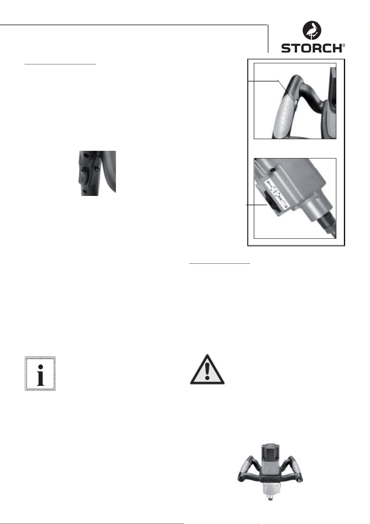
FONCTIONS DE BASE
Interrupteur marche/arrêt
Interrupteur marche/arrêt - Appuyer sur
l'interrupteur de marche pour démarrer l'outil. Pour
couper le moteur, relâcher l'interrupteur de marche.
Cet outil est équipé d'un bouton de blocage. Pour
un fonctionnement continu, actionner l'interrupteur
de marche et appuyer sur le bouton de blocage.
Pour mettre hors service, actionner de nouveau
l'interrupteur de marche puis le relâcher.
Réglage du régime
Pour une meilleure puissance de mélange avec des
produits à mélanger déterminés, le régime peut être
réglé électroniquement en tournant la molette de
réglage avec le pouce. Ill. 1.
Régulation du régime
Ill. 1
Sélecteur de rapport
(uniquement Quick
Mixx 50)
Ill. 2
Changement de rapport
Le mélangeur Quick Mixx 50 est équipé d'un sélecteur de rapport sur le carter d'engrenages. Pour
les produits à mélanger très visqueux, sélectionner
le régime faible. Mettre l'outil hors service avant le
réglage d'une plage de régime. Enfoncer le sélecteur
de rapport contre la force de ressort et le pousser
vers le haut ou vers le bas pour sélectionner la plage
de régime souhaitée. Veiller que le sélecteur de régime soit correctement enclenché. Tourner la broche
légèrement à la main facilite un couplage complet
du rapport. Ill.2
Mettre l'outil hors service avant le changement de rapport (OFF).
Remarque
Maniement de base
Domaines d'application
Pour un contrôle effi cace de cet outil, il est nécessaire
de le manier à deux mains pour une protection et une
stabilité optimales avec le couple de démarrage et
de service. Pour éviter une perte de contrôle, et les
éventuelles blessures qui en résulteraient, maintenir
l'appareil sûrement et dans les règles de l'art avec les
deux mains. Porter des lunettes de protection pour
éviter les blessures des yeux.
Maintenir le câble d'alimentation
secteur derrière l'opérateur et à distance
de la zone de travail pour empêcher
que le câble ne s'enroule avec le mé-
Attention !
langeur.
Poignées
Les poignées soft du mélangeur sont conçues pour
une prise optimale. Elles permettent à l'opérateur
une exploitation sans fatigue y compris lors de mises
en oeuvre prolongées.
25
Page 26
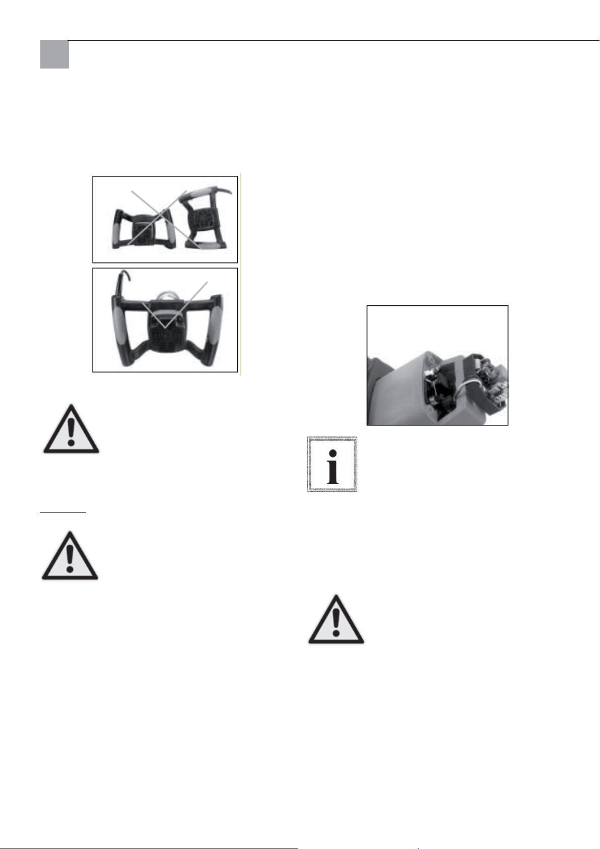
Position des poignées lors de la dépose
Procéder avec grande attention lors de la pose du
mélangeur électrique. Veiller à la position correcte
des poignées lors de la dépose.
Remplacer les balais de charbon
Remplacer les deux balais de charbon lorsque leur
longueur n'est plus que de 7 mm.. Afi n de contrôler
ou de remplacer les balais de charbon, commencer
par débrancher l'appareil. Dévisser le carter moteur
en desserrant les quatre vis. Tirer les ressorts des
balais de charbon en arrière afi n de relâcher la tensi-
on. Desserrer la vis tenant le guidage des balais de
charbon. Sortir les balais de charbon.
Répéter la procédure de l'autre côté. Procéder dans
l'ordre inverse lors du montage.
Les languettes côté métal de l'unité de balai rentrent
dans le même orifi ce que celui dans lequel les char-
bons entrent.
La dépose incorrecte de l'outil sur le sol
(par ex. avec le câble vers le bas) peut
endommager le câble d'alimentation
et augmenter ainsi le risque de choc
Attention !
électrique ainsi que la probabilité
d'endommagement de l'outil.
Entretien
Avant de procéder à l'entretien
de l'appareil, débrancher le câble
d'alimentation secteur pour réduire le
risque de blessure à la suite d'un dé-
Attention !
marrage inattendu ou du fait d'un choc
électrique.
Maintenir l'outil propre. Retirer la poussière accumulée sur les pièces mobiles. Veiller que l'outil fonctionne correctement. Contrôler régulièrement le bon
serrage des vis et boulons.
Nettoyage du mélangeur
Pour la mise en place des mêmes balais,
commencer par s'assurer que les balais
seront remis dans la position exacte
qu'ils avaient lors de leur retrait. Dans le
cas contraire, suite à une période de dé-
Remarque
marrage, la puissance du moteur pourrait
être réduite et l'usure des balais pourrait
être plus importante. Il est recommandé de faire procéder au moins une fois par an à un nettoyage et
un graissage complets de l'appareil par un centre de
service après-vente STORCH autorisé.
Pour garantir la sécurité et la fi abili-
té, toutes les réparation, à l'exception
des balais de charbon accessibles depuis l'extérieur, doivent être effectuées
par un centre de service après-vente
Attention !
STORCH autorisé.
Souffl er de l'air comprimé sec sur les fentes d'aération
toutes les 50 heures de service. Toutes les pièces de
plastique doivent être régulièrement nettoyées avec
un chiffon doux et humide. Ne JAMAIS nettoyer les
pièces en plastique à l'aide de solvants.
Lors des travaux avec de l'air comprimé, il faut porter des lunettes de protection. Après 200 heures de
mise en service, une station de service après-vente
STORCH qualifi ée devra remplacer le lubrifi ant.
26
Page 27
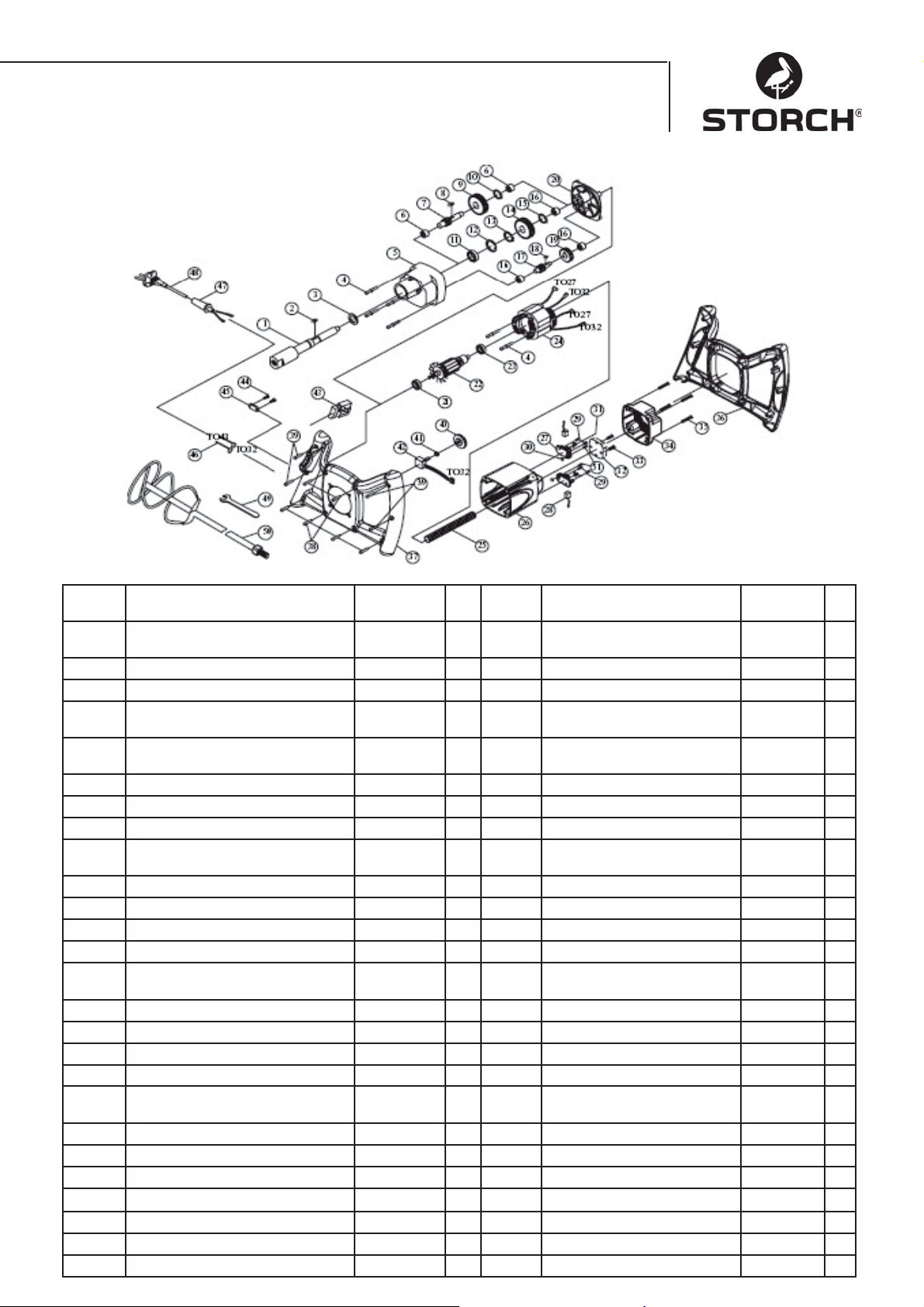
Nomenclature Quick Mixx 25
No.
d‘article
1 BROCHE M14xP2.0 1 27 SUPPORT DE BALAI DE
2 CLAVETTE ELASTIQUE 5x5x12 1 28 BALAI DE CHARBON 2
3 JOINT 22x32x7 1 29 VIS M4x12 4
4 VIS Y COMPRIS RONDELLE ELAS-
5 CARTER DE PROTECTION DES
6 ROULEMENT A AIGUILLES HK1010 2 32 CAPTEUR AVEC CEM 230V 1
7 ARBRE DE PIGNON 10T-080 1 33 VIS M4x25 2
8 CLAVETTE ELASTIQUE 5x5x10 1 34 CARTER MOTEUR 1
9 PIGNON DE RENVOI SUR ARBRE
10 BAGUE DE SECURITE S-12 1 36 PRISE (EN HAUT) 1
11 PALIER 6003ZZ 1 37 PRISE (EN BAS) 1
12 BAGUE DE SECURITE R-35 1 38 VIS M4X20
13 BAGUE DE SECURITE S-17 1 39 VIS M4X25 4
14 ROUE DENTEE 34T 1 40 ROUE DE REGLAGE DU
15 BAGUE DE SECURITE S-15 1 41 ECROU A SIX PANS 1/4“X34 1
16 ROULEMENT A AIGUILLES HK0810 3 42 REGIME ELECTRONIQUE
17 ARBRE DE PIGNON 14T 1 43 COMMUTATEUR 8301 230V 1
18 CLAVETTE ELASTIQUE 4X4X8 1 44 VIS M4X14 2
19 PIGNON DE RENVOI SUR ARBRE
20 CARTER D'ENGRENAGES 1 46 CABLE 16AWG 2
21 PALIER 609 2RS 1 47 PROTECTION DE CABLE 1
22 ANCRE 230V 1 48 CABLE D'ALIMENTATION 230V 1
23 PALIER 608ZZ 1 49 CLE PLATE M22 1
24 STATOR 230V 1 50 MELANGEUR A HELICE 1
25 GAINE PROTECTRICE DE CABLE M8 1 51 VIS M4x10 2
26 CARTER DU MOTEUR 1
Désignation pc. No.
d‘article
M5x60 6 30 ECROU A SIX PANS M4 2
TIQUE
1 1 31 RESSORT 2
ENGRENAGES
30T 1 35 VIS M5x20 4
INTERMEDIAIRE
37T 1 45 COLLIER DE CABLE 1
INTERMEDIAIRE
27
Désignation pc.
CHARBON
REGIME
REGL.B100K 1
2
1
Page 28
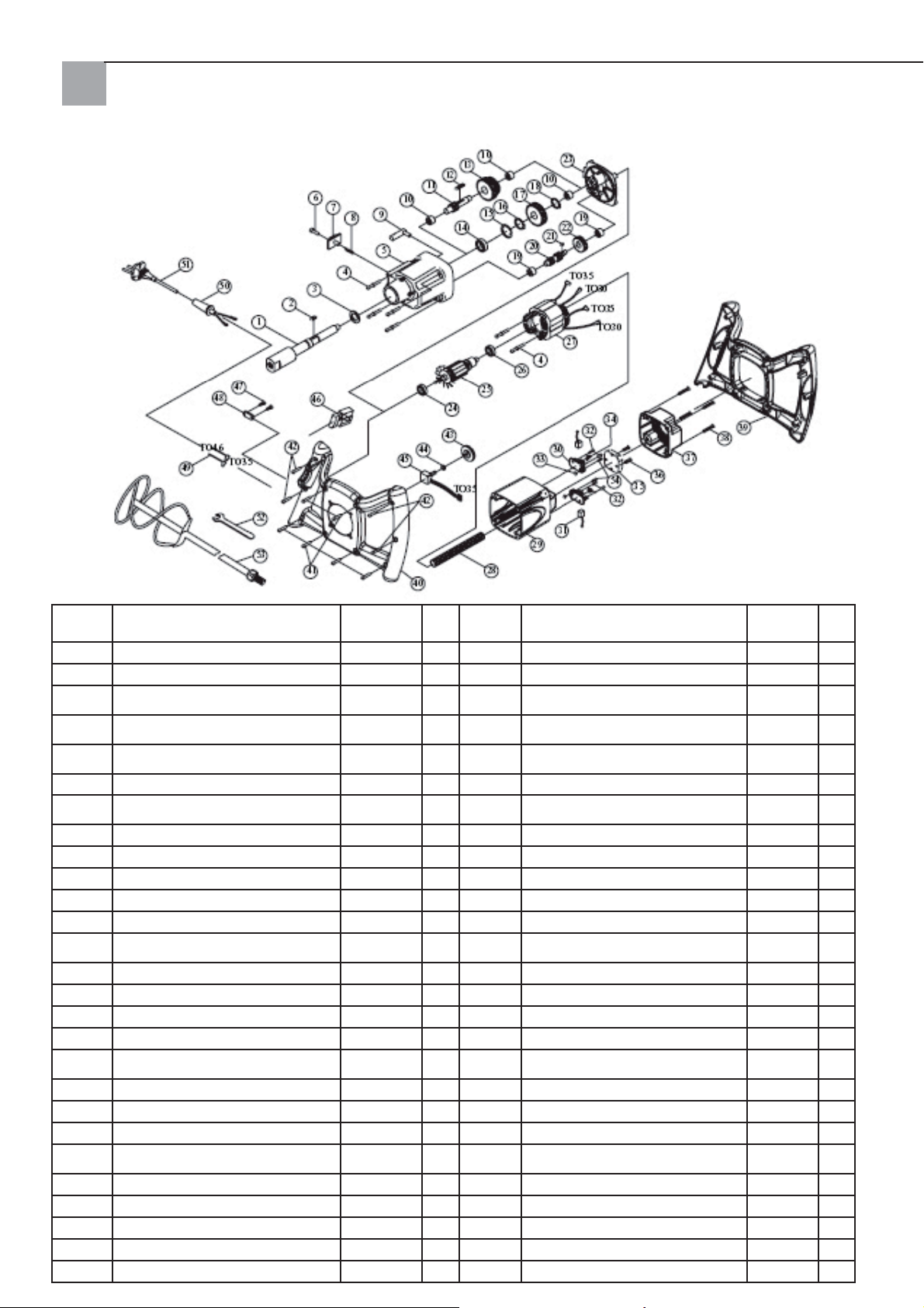
Nomenclature Quick Mixx 50
No.
d'article
1 BROCHE M14xP2.0 1 28 GAINE PROTECTRICE DE CABLE M8 1
2 CLAVETTE ELASTIQUE 5x5x12 1 29 CARTER DU MOTEUR 1
3 JOINT 2x32x7 1 30 SUPPORT DE BALAI DE CHAR-
4 VIS Y COMPRIS RONDELLE ELAS-
5 CARTER DE PROTECTION DES
6 VIS A FENTE 1 33 ECROU A SIX PANS M4 2
7 SELECTEUR DE RAPPORT COU-
8 RESSORT Ø6x0.6x4 1 35 CAPTEUR AVEC CEM 230 V 1
9 FOURCHE D'EMBRAYAGE 1 36 VIS M4x25 2
10 ROULEMENT A AIGUILLES HK1010 3 37 CARTER DE LOGEMENT MOTEUR 1
11 ARBRE DE PIGNON 10T-130 1 38 VIS M5x20 4
12 CLAVETTE ELASTIQUE 5x5x45 1 39 PRISE (EN HAUT) 1
13 PIGNON DE RENVOI SUR ARBRE
14 PALIER 6003ZZ 1 41 VIS M4x20 6
15 BAGUE DE SECURITE R-35 1 42 VIS M4x25 4
16 BAGUE DE SECURITE S-17 1 43 ROUE DE REGLAGE DU REGIME 1
17 ROUE DENTEE 34T 1 44 ECROU A SIX PANS 1/4“x34 1
18 BAGUE DE SECURITE S-15 1 45 REGULATEUR ELECTRONIQUE
19 ROULEMENT A AIGUILLES HK0810 2 46 COMMUTATEUR 8301 1
20 ARBRE DE PIGNON 14T&10T 1 47 VIS M4x14 2
21 CLAVETTE ELASTIQUE 4x4x8 1 48 COLLIER DE CABLE 1
22 PIGNON DE RENVOI SUR ARBRE
23 CARTER D'ENGRENAGES 1 50 ARMURE DE CABLE 1
24 PALIER 609 2RS 1 51 CABLE D'ALIMENTATION 230V 1
25 ANCRE 230V 1 52 CLE PLATE M22 1
26 PALIER 608ZZ 1 1 53 MELANGEUR A HELICE 1
27 STATOR 230V 1 54 VIS M4x10 2
Désignation Pce
TIQUE
ENGRENAGES
LISSANT
INTERMEDIAIRE
INTERMEDIAIRE
M5x60 6 31 BALAI DE CHARBON 2
1 32 VIS M4X12 4
1 34 RESSORT 2
30T&34T 1 40 PRISE (EN BAS) 1
37T 1 49 CABLE 16AWG 2
28
No.
d'article
Désignation Pce
BON
DE REGIME
B100K 1
2
Page 29

Déclaration de conformité CE
Nous déclarons sous notre propre responsabilité que le produit
Type : Quick Mixx 25, Quick Mixx 50
sur lequel cette déclaration se fonde, répond aux normes et documents de
normalisation suivants :
VDE 0740 - 1 : 2003-12
DIN EN 50144-1 : 2003-11
En conformité avec les dispositions des directives 98/37/CEE, 73/23/CEE,
89/336/CEE .
STORCH
Malerwerkzeuge & Profi geräte GmbH
Platz der Republik 6-8
D- 42107 Wuppertal
Jörg Heinemann – Directeur général
29
Page 30

I
Grazie mille
per la fi ducia che avete concesso a STORCH. Avete
scelto un prodotto di qualità.
Nel caso che abbiate delle proposte di miglioramento
oppure ci sia un problema, saremo pronti ad assisterVi. Contattate il Vostro rappresentante oppure
rivolgeteVi direttamente a noi in casi urgenti.
Distinti saluti
STORCH Reparto Assistenza
Tel.: +49 (0)2 02 .49 20 - 0
Fax +49 (0) 2 02 . 49 20 - 111
Contenuto Pagina
Dati tecnici 30
Materiale compreso nella consegna 30
Panoramica dell'apparecchio 31
Avvertenze di sicurezza 31
Allacciamento elettrico 32
Funzioni principali 34
Condotta principale 34
Pulizia dell'agitatore 35
Lista pezzi Quick Mixx 25 36
Lista pezzi Quick Mixx 50 37
Dati tecnici
Quick Mixx 25 Quick Mixx 50
Tensione 230 V ~ / 50 Hz 230 V ~ / 50
Hz
Potenza
d'ingresso
Potenza di
uscita (N-m)
Numero di
marce
Numero di giri
a vuoto
Tipo di protezione
Filettatura di
accoppiamento
Massimo
diametro
dell'agitatore
Regolazione
elettronica del
numero di giri
Peso 3,6 Kg 4,1 Kg
1100 watt 1300 watt
13,5 14,7
12
250~700 1. marcia
150~400
2. marcia
250~700
Classe 2 Classe 2
M14 M14
120 mm 140 mm
Sì Sì
Materiale compreso nella consegna
Miscelatore, chiave per montaggio, istruzioni per
l'uso
30
Page 31
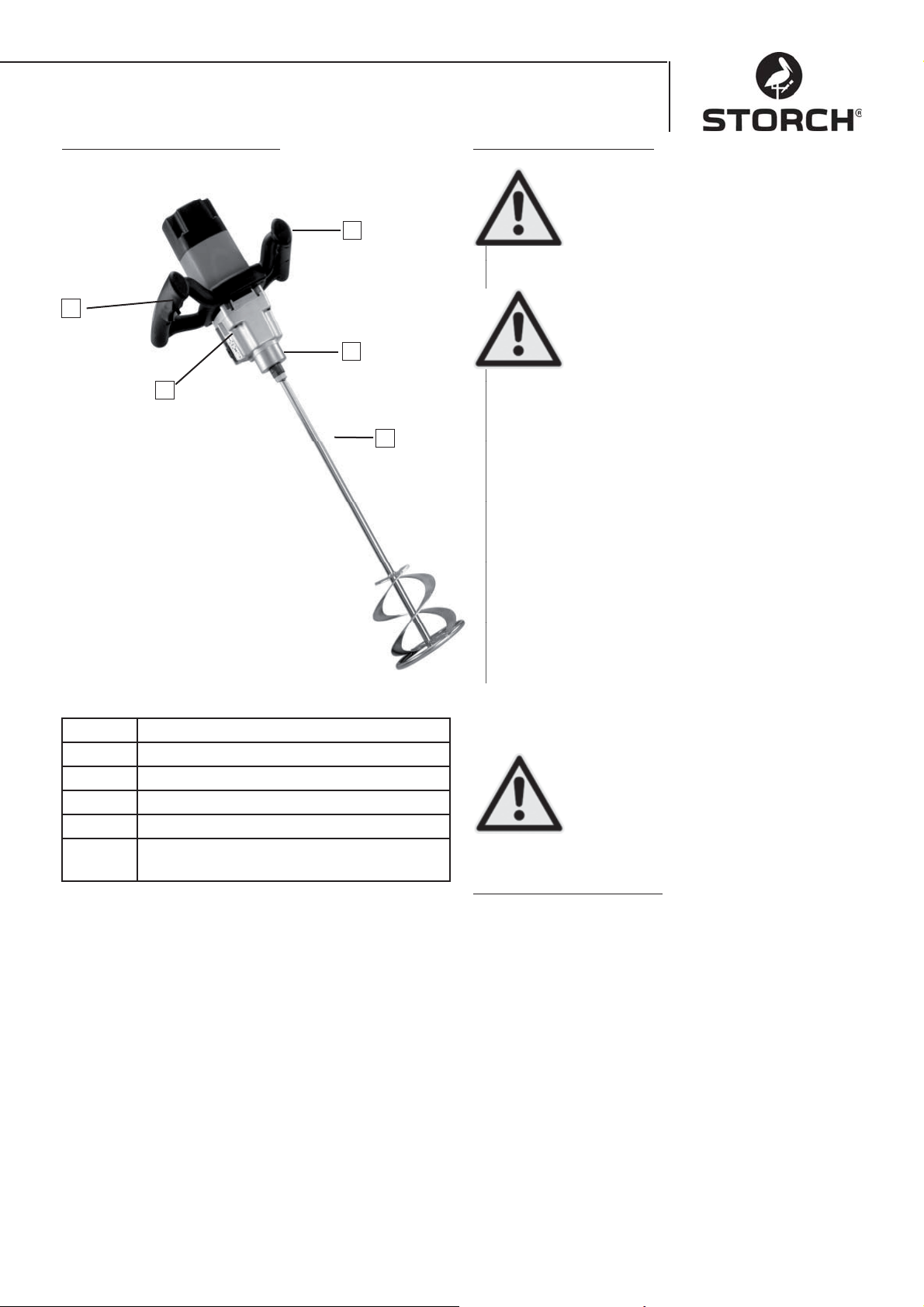
Panoramica dell'apparecchio
2
1
Avvertenze di sicurezza
Osservare questo simbolo che indica avvertenze di sicurezza importanti. Esso
signifi ca ATTENZIONE!!!
4
Attenzione!
Si tratta della Vostra sicurezza.
Prego leggere ed osservare tutte le avvertenze di sicurezza. Prima della messa in funzione dell'apparecchio si prega
3
di leggere le istruzioni per l'uso per garantire un funzionamento sicuro. Atten-
Attenzione!
tamente osservare tutte le avvertenze
di sicurezza e le indicazioni di pericolo.
Usare l'apparecchio esclusivamente per lo scopo
5
d'utilizzo previsto. L'inosservanza può causare dei
danni all'apparecchio oppure delle lesioni. Non eseguire delle modifi cazioni all'apparecchio!
Controllare l'apparecchio prima di ogni uso.
Controllare la connessione di parti mobili.•
Prima di inserire la spina elettrica portare •
l'interruttore ON / OFF in posizione OFF
Controllare l'integrità dei cavi.•
Controllare che non ci siano delle parti spezzate.•
1 Selettore rapporto (per Quick Mixx 50)
2 Interruttore ON/OFF con arresto
3 Portautensile
4 Regolatore numero di giri
5 Elica agitatrice (opzionale)
s. fi g. Chiave per montaggio (compreso nella
fornitura)
Eseguire con cura la manutenzione dell'apparecchio.
Tenere pulito l'utensile per assicurare la massima sicurezza e le prestazioni ottime.
Mai utilizzare l'apparecchio nelle vici-•
nanze di liquidi, vapori o gas infi amma-
bili.
Proteggere dall'umidità e dalla piog-•
gia.
Attenzione!
•
Durante il funzionamento
Durante il lavoro con materiale secco può formar-•
si della polvere. Per proteggere la salute l'area
di lavoro deve essere ben ventilata e si consiglia
l'utilizzo di maschere antipolvere. Osservare le
avvertenze di sicurezza del fabbricante del materiale.
Evitare di indossare vestiti lenti, sciarpe o gioielli •
(anelli, orologi da polso). Essi potranno impigliarsi nei pezzi in movimento. Indossare guanti di
protezione.
31
Page 32
Durante il funzionamento della macchina
Conservare queste avvertenze di sicurezza
Non permettere che la routine (dovuta
all'uso frequente dell'agitatore) non risulti in errori di disattenzione. Una
disattenzione anche per frazioni di se-
Attenzione!
condo può già risultare in gravi lesioni.
Nel caso che l'utensile faccia dei rumori strani •
oppure vibri fortemente, immediatamente interrompere il lavoro. Spegnere l'utensile. Staccare
la spina. Non mettere in funzione prima di aver
trovato ed eliminato il guasto.
Tener lontano dall'utensile e dal posto di lavoro •
tutti gli ospiti, spettatori e bambini.
Prima di disattivare l'utensile: Mai lasciare incustodito l'apparecchio funzionante
Spegnere l'apparecchio,•
Attendere affi nché tutte le parti mobili siano fer-•
me,
Staccare la spina.•
Durante il funzionamento di elettroutensili gli occhi
possono essere gravemente feriti a causa di corpi estranei catapultati fuori. Prima di mettere in funzione
l'utensile si consiglia di portare occhiali di protezione
con alette di protezione ed all'occorrenza una protezione totale. Consigliamo l'uso di occhiali a ciclope al
di sopra di occhiali da vista oppure occhiali di sicurezza standard con alette di protezione.
Organizzare l'offi cina in modo che la sicurezza dei
bambini non sia pregiudicata
• Chiudere l'offi cina a chiave
• Spegnere gli interruttori principali
• Conservare l'utensile in un luogo protetto dall'accesso di bambini e di perso-
Attenzione!
ne non qualifi cate.
Requisiti elettrici e relative al motore
ATTENZIONE: Utilizzare protezione del
circuito idonea per evitare il rischio di pericoli, il rischio di incendi oppure il danneggiamento dell'utensile. L'utensile è
Attenzione!
stato progettato per l'utilizzo con la ten-
sione indicata in alto. Collegare l'utensile
ad una linea di corrente con una tensione corrispondente ed una linea di diramazione da 16 ampere. Utilizzare un salvavita ritardato da 16 ampere oppure un
interruttore di sicurezza. Immediatamente sostituire
un cavo di rete usurato, tronco oppure danneggiato
per ridurre il rischio di una scossa elettrica oppure il
rischio di incendio.
Allacciamento elettrico
Collegare la spina con una presa con messa a terra
che corrisponde alle leggi e normi del luogo di applicazione. Non modifi care la
spina fornita. Nel caso che la spina non
entri nella presa far installare una presa
Avvertenza
adatta da un elettricista qualifi cato.
Un collegamento irregolamentare del
conduttore di terra può risultare in una scossa elettrica. Il conduttore con una schermatura verde con o
senza striscia gialla rappresenta il conduttore di terra. Nel caso che sia necessaria una riparazione oppure una sostituzione della spina oppure del cavo di rete
il conduttore di terra non deve essere collegato ad un
terminale sotto tensione.
Nel caso che il cavo di rete sia usurato, tronco oppure in qualsiasi modo danneggiato immediatamente
farlo sostituire da un elettricista qualifi cato. Nel caso
che le istruzioni riguardanti la messa a terra non siano completamente comprese oppure in caso di dubbi
sulla messa a terra regolamentare dell'utensile occorre far controllare l'utensile da un elettricista qualifi -
cato oppure presso un centro di assistenza STORCH.
32
Attenzione!
Badare che durante l'inserzione oppure
estrazione della spina elettrica non Vi
sia un contatto a dito con i collegamenti
della spina di rete per evitare il rischio
di lesioni oppure di morte dovuto allo
shock elettrico.
Page 33
Nel caso di una messa a terra irregolamentare questo utensile può far scattare una scotta elettrica, particolarmente
durante l'utilizzo in ambienti umidi, vicino a delle tubazioni oppure all'aperto.
Attenzione!
Nel caso di una scossa elettrica saranno
probabilmente causati dei pericoli secondari, p.es. a causa del contatto della pelle con
l'agitatore.
Sicurezza del motore
IMPORTANTE: Per evitare dei danni al motore,
questo motore deve essere spesso pulito con un aspirapolvere per non impedire la ventilazione normale
del motore attraverso della polvere.
Disimballaggio e controllo del materiale compreso
nella consegna
Disimballaggio
Per ridurre il pericolo di lesioni dovute
ad un avviamento inatteso oppure ad
una scossa elettrica non inserire la spina
elettrica nella presa durante il disimballaggio ed il montaggio dell'apparecchio.
Attenzione!
Eseguire tutti i lavori all'apparecchio
solo con cavo di rete staccato dalla
presa di corrente.
L'apparecchio sarà imballato e fornito completamente in un cartone.
Collegare l'apparecchio ad una rete con una ten-1.
sione corrispondente al modello ed una linea di
diramazione da 16 ampere con un salvavita da 16
ampere oppure un interruttore di sicurezza.
Nel caso che il motore non si avvii immediata-2.
mente portare l'interruttore in posizione "OFF" e
disinserire la spina di rete dell'utensile.
Nel caso di un blocco del motore imprevisto du-3.
rante il lavoro, rilasciare l'interruttore e staccare
l'apparecchio dalla presa. Ora il motore può essere avviato di nuovo.
Le seguenti situazioni possono spesso far scat-4.
tare i salvavita oppure gli interruttori di sicurezza
a) Il motore è sovraccaricato - Un sovraccarico
può occorrere quando si esegue un riempimento troppo in fretta oppure quando l'utensile va
spesso avviato e fermato in un breve tempo.
b) La tensione di rete non deve superare o essere inferiore del 10 % della tensione nominale
riportata sulla targhetta. In caso di carichi pesanti
la tensione applicata al motore deve esattamente corrispondere alla tensione indicata per questo
modello.
La maggior parte dei danni al motore può essere 5.
attribuita a collegamenti sciolti oppure difettosi,
al sovraccarico e ad una tensione troppo bassa
(ad esempio sezione troppo bassa dei conduttori nella rete) oppure a conduttori con una lunghezza eccessa nel circuito di alimentazione. Nel
caso che il motore non funzioni in modo regolare sempre controllare i collegamenti, il carico ed
il circuito di alimentazione. I conduttori devono
avere una sezione minima di 2,5mm².
Togliere l'utensile e tutte le parti sciolte dal car-•
tone.
Posare tutte le parti su una superfi cie di lavoro •
sicura e fi ssa ed accuratamente eseguire un con-
trollo visivo dell'utensile.
Prima di eseguire il montaggio controllare
la completezza delle parti. Nel caso che
una parte dovesse mancare, non montare
l'utensile. Verifi care la completezza delle
Avvertenza
parti controllando il materiale di imbal-
laggio. Alla fi ne di queste istruzioni Vi è
rappresentato un elenco pezzi. Identifi care il numero
categorico del pezzo mancante.
Nel caso di parti mancanti l'agitatore
elettrico non deve essere messo in funzione fi no a che le parti mancanti siano
sostituite. Altrimenti sono possibili delle
Attenzione!
gravi lesioni.
33
Page 34
Funzioni principali
Interruttore ON/OFF
Interruttore ON/OFF - Per avviare l'utensile premere
l'interruttore di accensione. Per spegnere il motore rilasciare l'interruttore di accensione. Questo utensile è
dotato da un pulsante i blocco. Per un funzionamento
continuo occorre premere l'interruttore di accensione
ed il pulsante di blocco. Per spegnere l'apparecchio
nuovamente premere l'interruttore di accensione e
rilasciarlo.
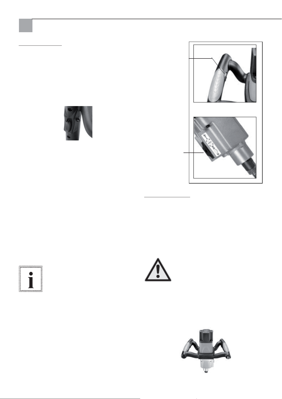
Impostazione del numero dei giri
Per ottenere la migliore potenza di mescolatura per
un determinato materiale è possibile elettronicamente regolare il numero di giri girando la rotella di regolazione con il pollice. Fig. 1.
Cambio di velocità
Il miscelatore Quick Mixx 50 è dotato da un selettore
di velocità sulla scatola del cambio. Per materiale
con alta viscosità occorre selezionare un numero di
giri basso. Prima di impostare un intervallo di regime
spegnere l'utensile. Premere il selettore di velocità
contro la tensione della molla ed spingerlo in alto oppure in basso per selezionare l'intervallo di regime
desiderato. Badare che il selettore di velocità scatti in posizione. L'innesto completo della marcia sarà
facilitato girando leggermente il mandrino a mano.
Fig. 2
Prima di cambiare la velocità prego spegnere l'utensile (OFF).
Regolatore numero di
giri
Fig. 1
Selettore rapporto
(solo Quick Mixx 50)
Fig. 2
Condotta principale
Settori d'impiego
Per un maneggio effi ciente dell'utensile occorre far-
lo funzionare con due mani per una massima protezione ed stabilità. Per evitare una perdita del controllo oppure eventuali lesioni risultanti mantenere
l'apparecchio in modo regolamentare e con due mani.
Per proteggere gli occhi da lesioni si consiglia l'uso di
occhiali di protezione.
Mantenere il cavo di rete dietro l'operatore
e fuori dall'area di lavoro per evitare che
il cavo si avvolga intorno all'agitatore.
Attenzione!
Avvertenza
Manici
I manici soft dell'agitatore sono progettati per offrire una presa ottimale. Essi consentono all'operatore
un funzionamento senza affaticamento anche dopo
tempi di impiego più lunghi.
34
Page 35
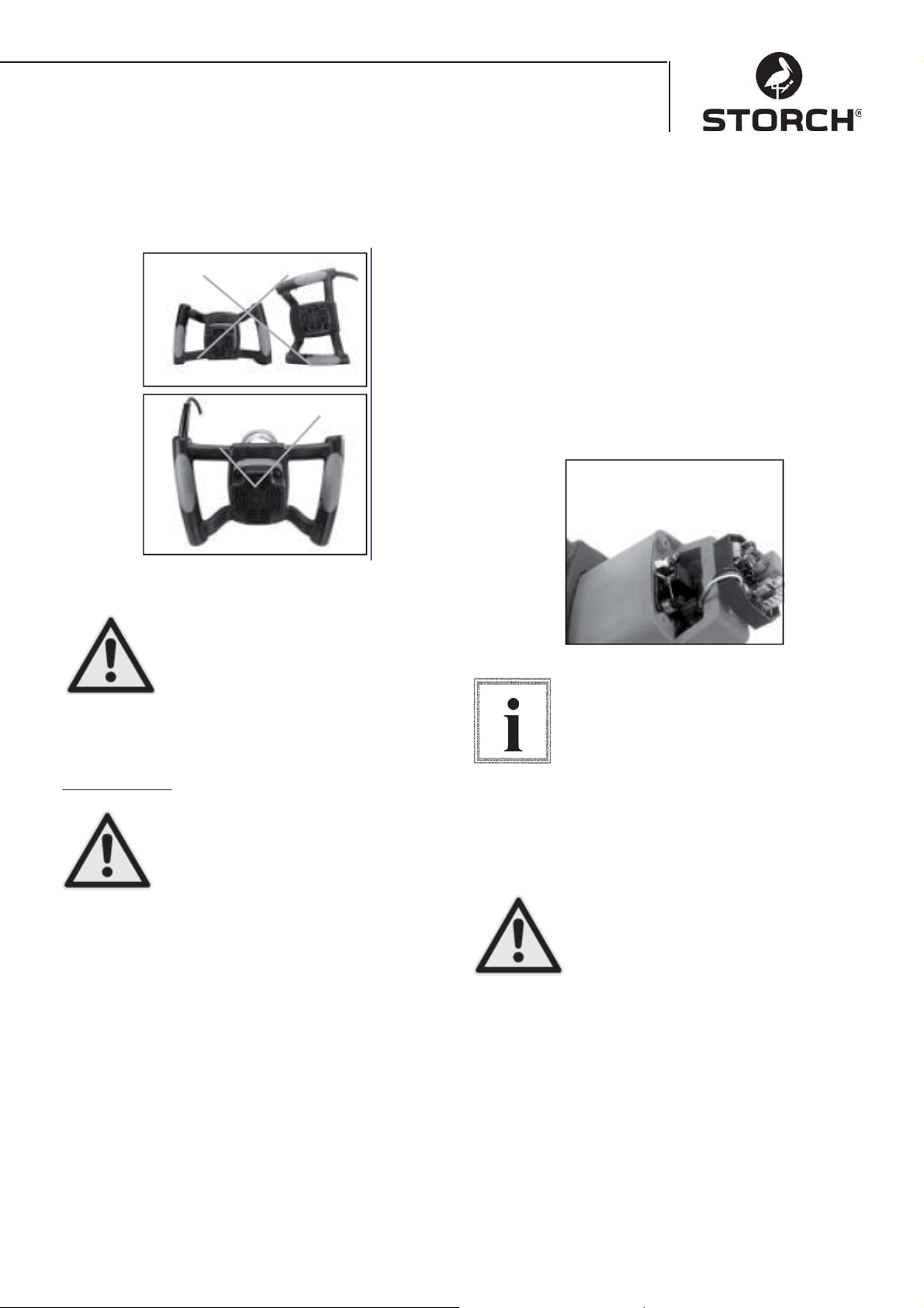
Posizione dei manici durante l'appoggio a terra
Procedere con attenzione quando si appoggia a terra l'agitatore elettrico. Badare alla posizione corretta
dei manici depositando l'apparecchio.
SOSTITUZIONE DELLE SPAZZOLE DI CARBONE
Nel caso che entrambe le spazzole a carbone siano
consumate fi no a 7 mm occorre sostituirle. Prima di
controllare oppure sostituire le spazzole di carbone
occorre disinserire l'apparecchio dalla rete. Svitare il
coperchio del motore allentando le quattro viti. Tirare
indietro le molle delle spazzole di carbone per ridurre
la tensione. Allentare la vite che fi ssa la guida della
spazzole di carbone. Tirare fuori la spazzola di carbone.
Ripetere il procedimento dall'altra parte. Per il montaggio, eseguire il procedimento in ordine inverso.
I coprigiunto sul lato di metallo dell'unità spazzole
devono essere inseriti nella stessa apertura dove entrano anche gli elementi di carbone.
Un deposito a terra irregolamentare
dell'utensile (p.es. con il cavo verso il
basso) può risultare nel danneggiamento del cavo di rete e di conseguenza
nell'aumento del rischio di una scossa
Attenzione!
elettrica come anche nel danneggia-
mento dell'apparecchio.
Manutenzione
Prima di eseguire la manutenzione
dell'apparecchio staccare la spina per
ridurre il rischio di lesioni dovute ad
un avviamento inatteso oppure ad una
Attenzione!
scossa elettrica.
Tener pulito l'utensile. Rimuovere la povere da parti
mobili. Badare che l'utensile lavori in maniera regolamentare. Controllare che le viti ed i bulloni siano
fi ssati in maniera corretta.
Pulizia dell'agitatore
Regolarmente dopo 50 ore di esercizio pulire le fessure di ventilazione con aria compressa. Regolarmente pulire tutte le parti di plastica con un panno
morbido e umido. MAI pulire le parti di plastica con
solventi.
Durante il lavoro con aria compressa, sempre portare
occhiali di protezione. Dopo 200 ore di esercizio il
lubrifi cante del cambio deve essere sostituito presso
una stazione di assistenza qualifi cata STORCH.
Quando si vuole inserire le spazzole
stesse assicurarsi che esse vengano inserite nello stesso modo come per rimuoverle. Altrimenti a causa di una fase di
Avvertenza
assestamento la potenza del motore può
essere ridotta e l'usura delle spazzole
aumenta. Si consiglia una pulizia intera come anche
una lubrifi cazione dell'apparecchio ogni anno presso
un centro assistenza STORCH autorizzato.
Per garantire la sicurezza e l'affi dabilità
dell'apparecchio occorre far eseguire tutti i lavori di riparazione presso un centro
di assistenza autorizzato STORCH eccetto le spazzole di carbone raggiungi-
Attenzione!
bili dall'esterno.
35
Page 36
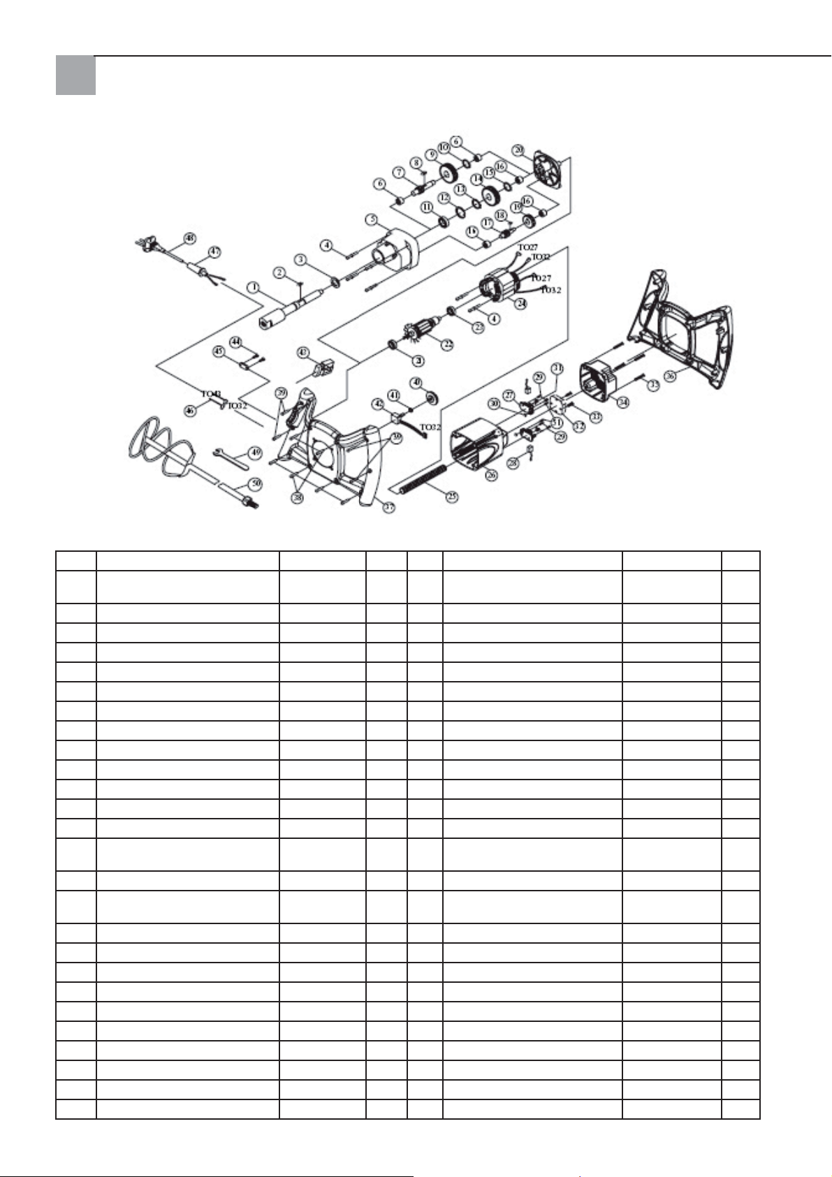
Lista pezzi Quick Mixx 25
Cod. Descrizione Pz. Cod. Descrizione Pz.
1 MANDRINO M14xP2.0 1 27 SUPPORTO PER SPAZZOLA
2 LINGUETTA 5x5x12 1 28 SPAZZOLA DI CARBONE 2
3 GUARNIZIONE 22x32x7 1 29 VITE M4x12 4
4 VITE INCL. LINGUETTA M5x60 6 30 DADO ESAGONALE M4 2
5 SCATOLA DEL CAMBIO 1 1 31 MOLLA 2
6 CUSCINETTO AD AGHI HK1010 2 32 SENSORE CON EMC 230 V 1
7 ALBERO PORTAPIGNONE 10T-080 1 33 VITE M4x25 2
8 LINGUETTA 5x5x10 1 34 COPERCHIO MOTORE 1
9 RUOTA DEL RINVIO 30T 1 35 VITE M5x20 4
10 ANELLO DI SICUREZZA S-12 1 36 MANICO (IN ALTO) 1
11 CUSCINETTO 6003ZZ 1 37 MANICO (IN BASSO) 1
12 ANELLO DI SICUREZZA R-35 1 38 VITE M4X20
13 ANELLO DI SICUREZZA S-17 1 39 VITE M4X25 4
14 RUOTA DENTATA 34T 1 40 ROTELLA DI REGOLAZIONE
15 ANELLO DI SICUREZZA S-15 1 41 DADO ESAGONALE 1/4“X34 1
16 CUSCINETTO AD AGHI HK0810 3 42 REGOLATORE ELETTRONICO
17 ALBERO PORTAPIGNONE 14T 1 43 INTERRUTTORE 8301 230V 1
18 LINGUETTA 4X4X8 1 44 VITE M4X14 2
19 RUOTA DEL RINVIO 37T 1 45 SERRACAVO 1
20 COPERCHIO DEL CAMBIO 1 46 CAVO 16AWG 2
21 CUSCINETTO 609 2RS 1 47 ARMATURA CAVI 1
22 INDOTTO 230 V 1 48 CAVO DI RETE 230 V 1
23 CUSCINETTO 608ZZ 1 49 CHIAVE PER DADI M22 1
24 STATORE 230 V 1 50 AGITATORE AD ELICA 1
25 TUBO PARACAVI M8 1 51 VITE M4x10 2
26 SCATOLA DEL MOTORE 1
DI CARBONE
NUMERO DI GIRI
DI GIRI B100K 1
NUMERO
2
1
36
Page 37
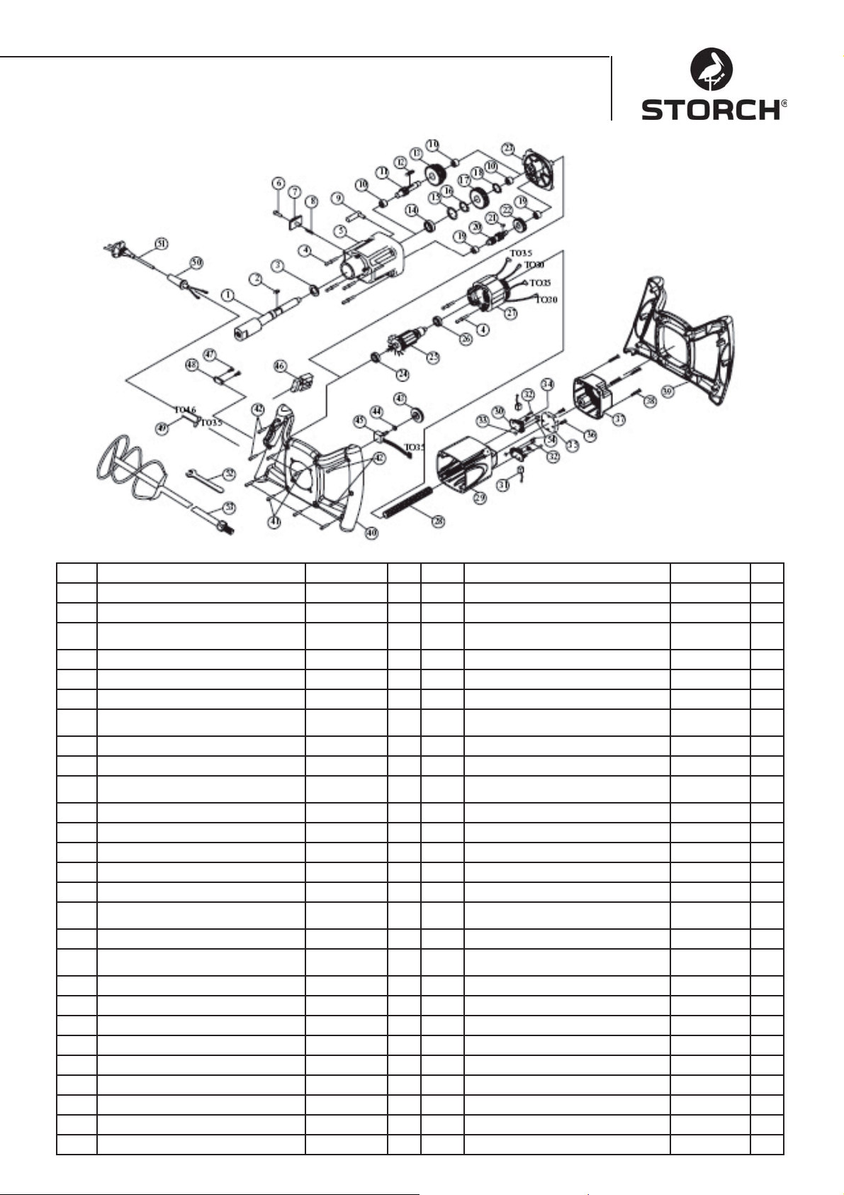
Lista pezzi Quick Mixx 50
Cod. Descrizione Pz. Cod. Descrizione Pz.
1 MANDRINO M14xP2.0 1 28 TUBO PARACAVI M8 1
2 LINGUETTA 5x5x12 1 29 SCATOLA DEL MOTORE 1
3 GUARNIZIONE 2x32x7 1 30 SUPPORTO PER SPAZZOLA DI
4 VITE INCL. LINGUETTA M5x60 6 31 SPAZZOLA DI CARBONE 2
5 SCATOLA DEL CAMBIO 1 32 VITE M4X12 4
6 VITE CON TESTA AD INTAGLIO 1 33 DADO ESAGONALE M4 2
7 INTERRUTTORE A SCORRIMENTO
SELEZIONE MARCIA
8 MOLLA Ø6x0.6x4 1 35 SENSORE CON EMC 230 V 1
9 FORCELLA DI COMANDO 1 36 VITE M4x25 2
10 CUSCINETTO AD AGHI HK1010 3 37 COPERCHIO DELLA SCATOLA
11 ALBERO PORTAPIGNONE 10T-130 1 38 VITE M5x20 4
12 LINGUETTA 5x5x45 1 39 MANICO (IN ALTO) 1
13 RUOTA DEL RINVIO 30T&34T 1 40 MANICO (IN BASSO) 1
14 CUSCINETTO 6003ZZ 1 41 VITE M4x20 6
15 ANELLO DI SICUREZZA R-35 1 42 VITE M4x25 4
16 ANELLO DI SICUREZZA S-17 1 43 ROTELLA DI REGOLAZIONE NU-
17 RUOTA DENTATA 34T 1 44 DADO ESAGONALE 1/4“x34 1
18 ANELLO DI SICUREZZA S-15 1 45 REGOLATORE ELETTRONICO
19 CUSCINETTO AD AGHI HK0810 2 46 INTERRUTTORE 8301 1
20 ALBERO PORTAPIGNONE 14T&10T 1 47 VITE M4x14 2
21 LINGUETTA 4x4x8 1 48 SERRACAVO 1
22 RUOTA DEL RINVIO 37T 1 49 CAVO 16AWG 2
23 COPERCHIO DEL CAMBIO 1 50 ARMATURA CAVI 1
24 CUSCINETTO 609 2RS 1 51 CAVO DI RETE 230 V 1
25 INDOTTO 230 V 1 52 CHIAVE PER DADI M22 1
26 CUSCINETTO 608ZZ 1 1 53 AGITATORE AD ELICA 1
27 STATORE 230 V 1 54 VITE M4x10 2
1 34 MOLLA 2
37
CARBONE
MOTORE
MERO DI GIRI
NUMERO DI GIRI
B100K 1
2
1
1
Page 38

Dichiarazione di conformità CE
Dichiaramo in sola responsabilità che il prodotto
Tipo: Quick Mixx 25, Quick Mixx 50
al quale va fatto riferimento in questa dichiarazione, concordi con le seguenti norme e
documenti normativi.
VDE 0740 - 1 : 2003-12
DIN EN 50144-1 : 2003-11
Secondo le norme delle direttive 98/37/CEE, 73/23/CEE, 89/336/CEE.
STORCH
Malerwerkzeuge & Profi geräte GmbH
Platz der Republik 6-8
42107 Wuppertal
Jörg Heinemann – Direttore generale
38
Page 39
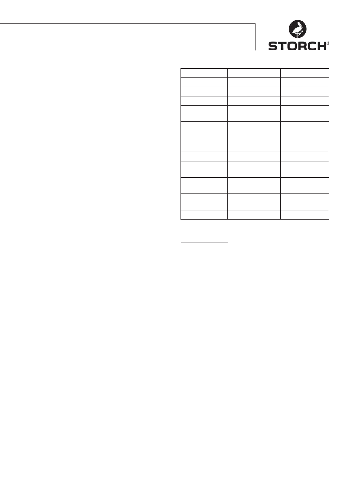
GB
Many thanks
for your confi dence in STORCH. You have bought a
high quality product.
However, if you should have any suggestions for improvement or perhaps a problem, then we would be
pleased to hear from you. Please speak to your area
representative or in urgent cases you can contact us
directly.
Yours sincerely,
STORCH service department
Tel. +49 (0)2 02 . 49 20 - 112
Fax +49 (0)2 02 . 49 20 - 244
Contents Page
Technical specifi cations 39
Scope of delivery 39
Tool overview 40
Safety Precautions 40
Electrical connection 41
Basic functions 43
Basic use 43
Cleaning the mixer 44
Item list Quick Mixx 25 45
Item list Quick Mixx 50 46
Technical data
Quick Mixx 25 Quick Mixx 50
Voltage 230V / 50Hz 230V / 50Hz
Power Input 1100 Watt 1300 Watt
Output (N-m) 13.5 14.7
Number of
gears
No load Speed 250~700 1. gear
Protection Class 2 Class 2
Coupling th-
read
Mixer stick
max. diameter
Electronic
speed control
Net weight 3.6 kg 4.1 kg
List of Contents
Mixer, assembly key, operating instructions
12
150~400
2. gear
250~700
M14 M14
120 mm 140 mm
Yes Yes
39
Page 40
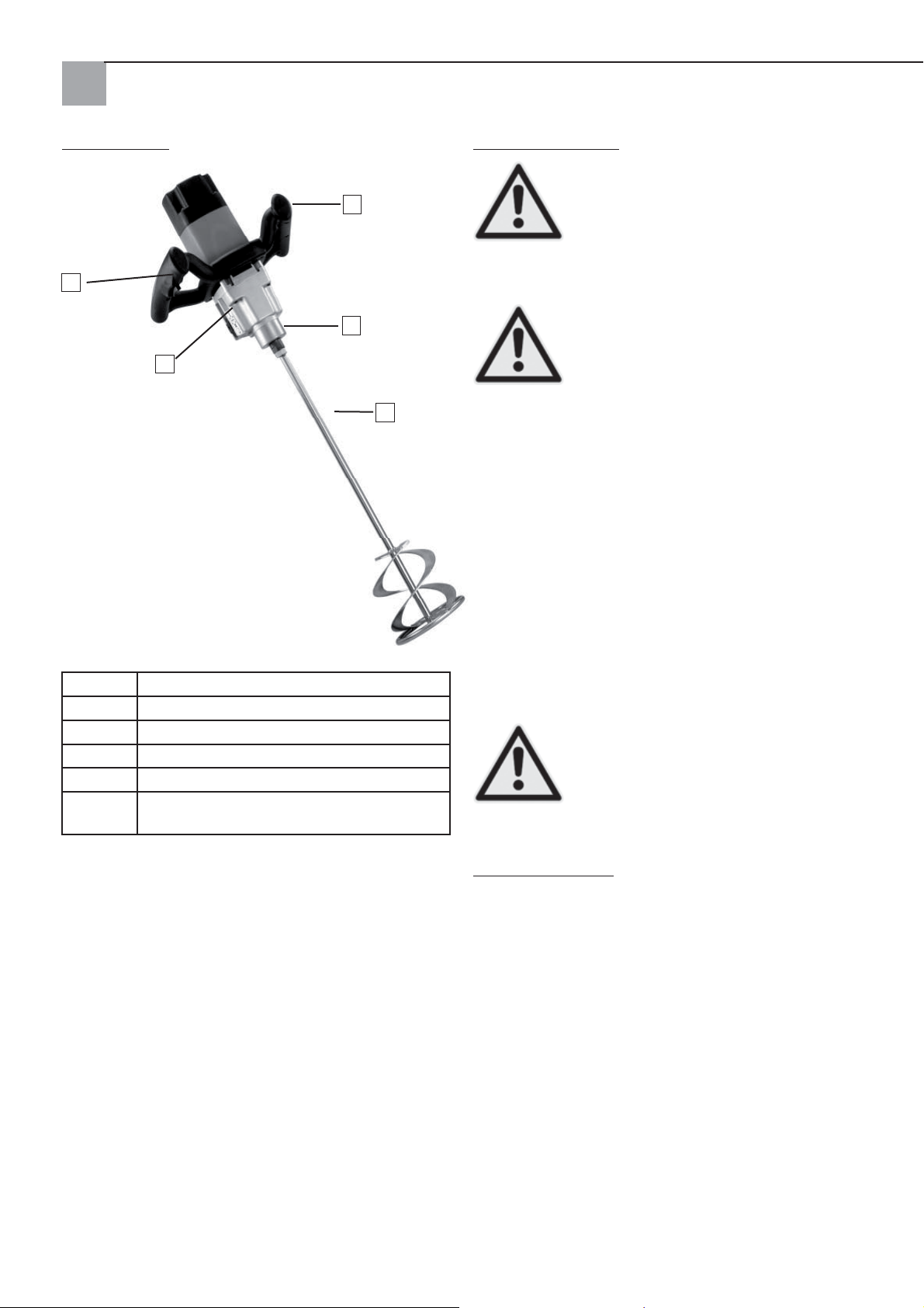
Tool overview
Safety Precautions
Look for this symbol to point out impor-
4
Caution!
tant safety precautions. It means ATTENTION!!!
Your safety is involved.
2
3
1
5
1 Gear selector switch (for Quick Mixx 50)
2 On/off switch with stop
3 Tool holder
4 Speed adjuster
5 Mixing coil (optional)
No pic-
ture
Assembly key (supplied)
Please read and observe all operating
and safety instructions. Before starting
up the device please read the operating
instructions in full to ensure safe opera-
Caution!
the use for which it is designed. Failure to observe
these instructions can damage the device or lead to
injury. Do not alter the tool in any way.
Check the tool before each use.
• Check moving parts are properly connected
• Switch the on/off switch to off before plug
ging in
• Check to ensure no cables are damaged.
• Check to ensure there are no broken parts.
Handle with care. Keep the tool clean to ensure optimum safety and performance.
Caution!
tion. Observe all safety advice, and dan-
gers and warnings. Only use the tool for
• Never use near fl ammable liquids,
steam or gas.
• Protect from damp and rain.
During operation:
There may be dust when mixing dry goods. •
For health and safety reasons the working area
should be well ventilated and the user should
always wear a mask and safety goggles. Please
observe the safety instructions issued by the material producer.
Do not wear wide clothes, scarves or jewellery •
(rings, watches). These could get caught up in
the moving parts. Wear protective gloves.
40
Page 41
Whenever Machine Is Running
Save these Instructions
Do not allow a routine to set in (from fre-
quent use) and allow errors to be made.
Loss of attention for even microseconds
Caution!
If the tool makes unusual noises or vibrates stron-•
gly immediately stop and switch off the device.
Unplug. Do not start up again until the fault has
been identifi ed and rectifi ed.
Keep the tool and workplace out of reach of all •
visitors, observers and children.
Before setting the tool down: never leave the running tool unattended.
• Switch the tool off,
• Wait for all moving parts to stop,
• Unplug from power outlet.
When operating electric tools foreign particles can
be propelled into the eyes, leading to serious eye
injury. Before starting up the tool always put on
satefy goggles with side protection or full facial
protection if necessary. We recommend the use of
a visor to wear over prescription glasses or standard
safety glasses with side protection.
Make Workshop Child Proof
can lead to serious injury.
• Lock the workshop
• Switch off the mains switch
• Always store out of reach of children
or other unauthorised persons.
Motor and Electrical Requirements
CAUTION: Use a proper circuit protection
to reduce the risk of electric shock, fi re or
damage to the tool. The tool is designed
to be operated in the above mentioned
Caution!
a 16 amp branch lead. Use a delay-action 16 amp
fuse or a safety switch. If the cable is worn, cut or damaged in any way it should be immediately replaced
to reduce the risk of fi re and electric shock.
Electrical Connections
Note
Improper connection of the equipment-grounding
conductor can result in a risk of electric shock. The
conductor with insulation having an outer surface
that is green with or without yellow stripes is the
equipment-grounding conductor. If repair or replacement of the electric cord or plug is necessary, do not
connect the equipment-grounding conductor to a live
terminal.
voltages. Connect the tool to power cir-
cuit with the correct voltage and connect
The plug must be plugged into a
matching outlet that is properly installed
and grounded in accordance with all local codes and ordinances. Do not modify
the plug provided. If it will not fi t the
outlet, have the proper outlet installed
by a qualifi ed electrician.
Caution!
If the cable is worn, cut or damaged in any way it
should be immediately replaced by a qualifi ed electri-
cian. If the instructions on earthing are not clear or if
in doubt, this should be checked by a qualifi ed electri-
cian or by the STORCH service station.
Ensure that you do not touch the connections of the plug when plugging in
and unplugging the tool, so as to prevent injury or a potentially fatal electric
Caution!
shock.
41
Page 42
If not properly earthed this tool can
cause an electric shock especially if
used in damp conditions, near pipes or
outside. An electric shock can also cause
secondary dangers, e.g. if the operator
Caution!
Motor Safety Protection
is touching the mixer.
Unpacking and Checking Contents
Unpacking
To minimise the risk of injury by unexpected start-up or electric shock during
unpacking and fi tting the plug, do not
plug in. The mains cable always has to
Caution!
be unplugged if working on the tool.
Important: To prevent damage to the motor this motor has to be regularly blown out or vacuum cleaned
so that the normal motor ventilation is not affected
by dust.
Connect this tool to a power source with the ap-1.
propriate voltage for your model and a 1 6-amp
branch circuit with a 16-amp time delay fuse or
circuit breaker.
If the motor won’t start, turn the switch “OFF” 2.
immediately and unplug the tool.
If the motor suddenly jams during mixing, release 3.
the switch and unplug the tool. The motor can
then be restarted.
For the following reasons fuses can of-4.
ten blow or safety switches shut down
a)Motor has overheated - this can occur if fi lling up too
fast or if the tool is started up and stopped frequently.
b)Line voltages should not be more than 10%
above or below the nameplate voltage. For heavy
loads, however, the voltage at motor terminals
must equal the voltage specifi ed for your model.
Most motor damage can be attributed to loose or 5.
faulty connections, overload or too low voltage
(e.g. if the lead cross section in the mains power
is too small) or excessively long leads in the power supply. If the motor is not operating smoothly,
always check the connections, the load and the
power supply cycle. The lead cross section should
not be less than 2.5 mm2.
The tool is supplied in a box.
Remove the tool and all loose parts from the car-•
ton.
Place all parts on a secure, stationary work sur-•
face and look the machine over carefully.
Before assembly check to ensure that no
parts are missing. If some are missing,
do not assemble. Check the packaging to
see if the missing parts are still in there.
There is a full list of parts at the end of
Note
Caution!
these instructions. Use the list to identify
any missing parts.
If any parts are missing do not use the
electric mixer until the parts have been
replaced. This could otherwise result in
severe injury.
42
Page 43
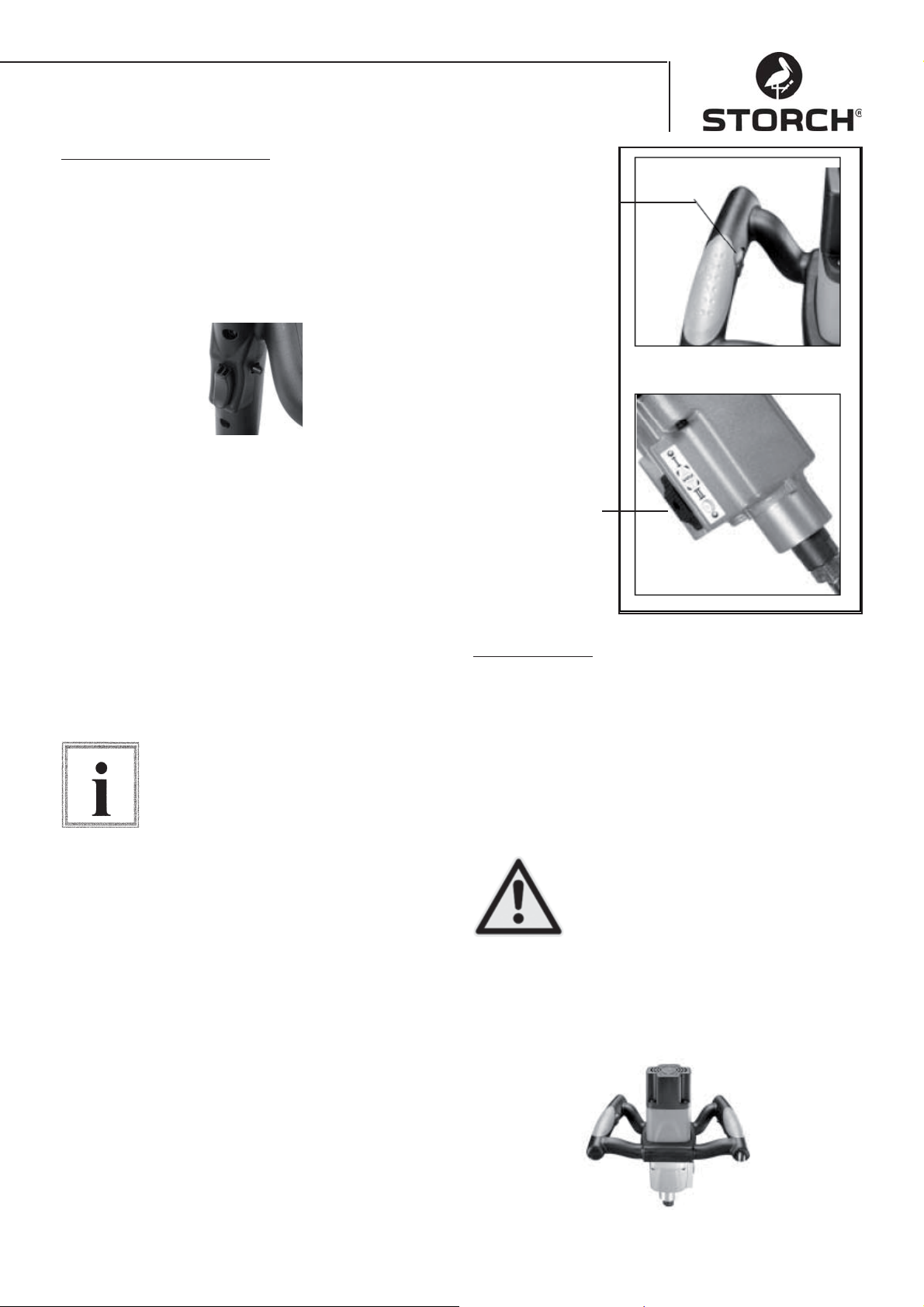
Basic Functional Operation
On / off switch
On / off switch - Press the on switch to start up. To
switch off release the button. This tool has a fi xed
position button. For constant use switch the on
switch and press the fi xed position button. To switch
off push the on switch again and then release.
Setting the speed
For the best mixing performance the speed can be
electronically set by turning the knob. See fi gure 1.
Switch gear
The Quick Mixx 50 has a gear selector switch on the
casing. For high viscosity materials select the low
speed. Before seting the spped switch off the tool.
Then press the gear sleector switch against the spring
tension and push up or down to adjust the speed. Ensure that the gear selector switch locks into place.
Slightly turning the spinlde makes it easier to fully
engage the gear. See fi gure 2.
Please switch the tool off before changing the gear (OFF).
Note
Speed adjuster
Fig.1
Gear selector switch
(only Quick Mixx 50)
Fig.2
Basic operation
Applications
Effective control of this machine requires two-handed
operation for maximum protection and resistance to
the start-up and operating torque. To avoid loss of
control and thereby any damage or injury, the tool
should be held properly and securely with both hands.
Protect your eyes from injury with safety glasses or
goggles.
Keep the mains cable behind the operator and the working area, to prevent the
cable being caught up in the mixer.
Caution!
Handles
The soft handles are designed to ensure maximum
grip. They avoid strain, even after prolonged use.
43
Page 44
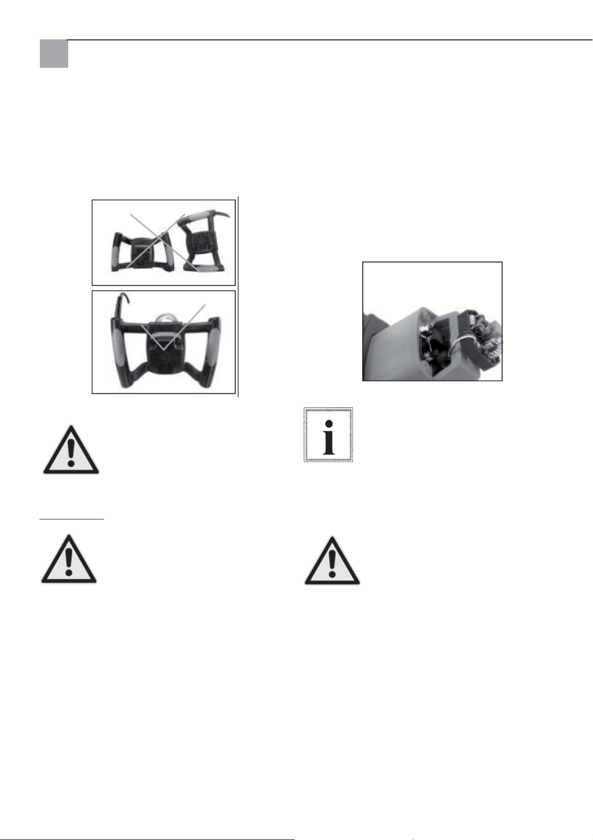
Grip positions when starting up
Please be careful when starting up the electric mixe
Ensure you are holding it properly.
Replacing Carbon Brushes
If worn down to 7 mm both carbon brushes should
be replaced. To check or replace the carbon brushes,
disconnect the tool from the power supply. Then unscrew the four motor casing screws. Pull back the
carbon brush springs to release the tension. Release
the screw holding the carbon brush guide. Remove
the carbon brush.
Repeat for the other side. To reassemble reverse the
procedure.
The straps on the metal of the brush unit are fi tted
into the same opening as the carbon parts.
If the device is not placed properly on
the fl oor (e.g. with the cable facing
down) the mains cable can be damaged, increasing the risk of electric show
Caution!
Maintenance
Caution!
lated dust from working parts. Make sure that the
tool operates properly. Periodically check screws and
bolts for tightness.
Cleaning the mixer
After about 50 running hours use pressurised dry air
to clean all ventilation slots. Regularly wipe plastic
parts with a soft, damp cloth. NEVER clean plastic
parts with solvents.
When working with pressurised air wear safety goggles. After about 200 hours of running time the
lubricant should be replaced by a qualifi ed STORCH
Service Station.
and the risk of damage to the tool.
Before servicing the tool disconnect the
power supply to reduce the risk of injury
from an unexpected start up or electric
shock.
Keep the tool clean. Remove accumu-
To fi t the same brushes fi rst ensure that
the brushes are replaced in exactly the
same way as before they were removed.
The motor performance can otherwise be
affected and the brushes will be subject
Note
authorised by STORCH at least once a year for a full
clean and lubrication.
Caution!
to more wear and tear. It is advisable to
send the tool to customer service unit
To ensure safety and reliability, all repairs with the exception of carbon
brushes that can be externally access,
should be carried out in a customer service centre authorised by STORCH.
44
Page 45
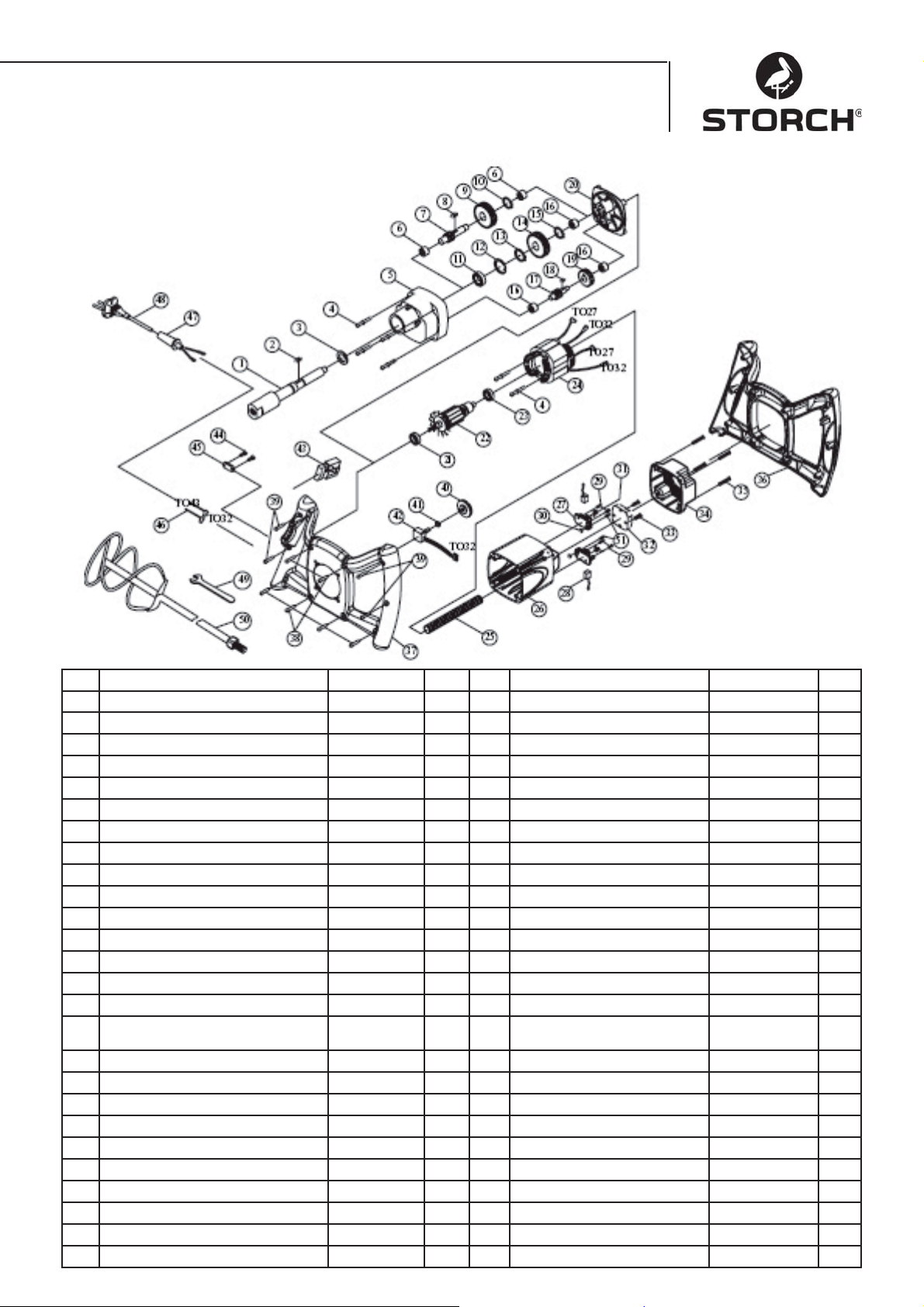
Item list Quick Mixx 25
No. Parts Name Pce. No. Parts Name Pce.
1 SPINDLE M14xP2.0 1 27 CARBON BRUSH HOLDER 2
2 WOODRUFF KEY 5x5x12 1 28 CARBON BRUSH 2
3 SEAL 22x32x7 1 29 SCREW M4x12 4
4 SCREW INCL WOODRUFF KEY M5x60 6 30 HEX. NUT M4 2
5 GEAR CASE 1 1 31 SPRING 2
6 NAIL BEARING HK1010 2 32 SENSOR WITH EMC 230 V 1
7 LAYSHIFT GEAR 10T-080 1 33 SCREW M4x25 2
8 WOODRUFF KEY 5x5x10 1 34 MOTOR TAIL CASTING 1
9 LAYSHIFT GEAR 30T 1 35 SCREW M5x20 4
10 LOCK RING S-12 1 36 HANDLE (TOP) 1
11 BEARING 6003ZZ 1 37 HANDLE (BOTTOM) 1
12 LOCK RING R-35 1 38 SCREW M4X20
13 LOCK RING S-17 1 39 SCREW M4X25 4
14 GEAR 34T 1 40 SPEED ADJUSTOR WHEEL 1
15 LOCK RING S-15 1 41 HEX. NUT 1/4“X34 1
16 NAIL BEARING HK0810 3 42 ELECTRONIC SPEED
17 LAYSHIFT GEAR 14T 1 43 SWITCH 8301 230V 1
18 WOODRUFF KEY 4X4X8 1 44 SCREW M4X14 2
19 LAYSHIFT GEAR 37T 1 45 CABLE CLIP 1
20 DRIVE COVER 1 46 CABLE 16AWG 2
21 BEARING 609 2RS 1 47 CABLE ARMOUR 1
22 ARMATURE 230 V 1 48 POWER SUPPLY CABLE 230 V 1
23 BEARING 608ZZ 1 49 WRENCH M22 1
24 STATOR 230 V 1 50 DYNAMIC MIXER 1
25 CABLE PROTECTION PIPE M8 1 51 SCREW M4x10 2
26 MOTOR HOUSING 1
45
ADJUSTOR
.B100K
1
Page 46
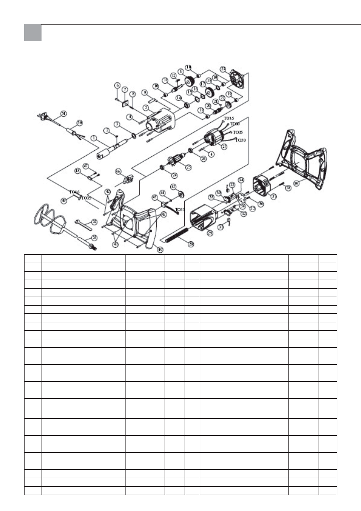
Item list Quick Mixx 50
No. Parts Name Q'TY No. Parts Name Q'TY
1 SPINDLE M14xP2.0 1 28 CABLE PROTECTION PIPE M8 1
2 WOODRUFF KEY 5x5x12 1 29 MOTOR HOUSING 1
3 SEAL 2x32x7 1 30 CARBON BRUSH HOLDER 2
4 SCREW INCL WOODRUFF KEY M5x60 6 31 CARBON BRUSH 2
5 GEAR CASE 1 32 SCREW M4X12 4
6 SLOTTED SCREW 1 33 HEX. NUT M4 2
7 SWITCH GEAR SLIDE SWITCH 1 34 SPRING 2
8 SPRING Ø6x0.6x4 1 35 SENSOR WITH EMC 230V 1
9 SHIFT FORK 1 36 SCREW M4x25 2
10 NAIL BEARING HK1010 3 37 MOTOR CASING COVER 1
11 LAYSHIFT GEAR 10T-130 1 38 SCREW M5x20 4
12 WOODRUFF KEY 5x5x45 1 39 HANDLE (TOP) 1
13 LAYSHIFT GEAR 30T&34T 1 40 HANDLE (BOTTOM) 1
14 BEARING 6003ZZ 1 41 SCREW M4x20 6
15 LOCK RING R-35 1 42 SCREW M4x25 4
16 LOCK RING S-17 1 43 SPEED ADJUSTOR WHEEL 1
17 GEAR 34T 1 44 HEX. NUT 1/4“x34 1
18 LOCK RING S-15 1 45 ELECTRONIC SPEED ADJUST-
19 NAIL BEARING HK0810 2 46 SWITCH 8301 1
20 LAYSHIFT GEAR 14T&10T 1 47 SCREW M4x14 2
21 WOODRUFF KEY 4x4x8 1 48 CABLE CLIP 1
22 LAYSHIFT GEAR 37T 1 49 CABLE 16AWG 2
23 DRIVE COVER 1 50 CORD ARMOR 1
24 BEARING 609 2RS 1 51 POWER SUPPLY CABLE 230 V 1
25 ARMATURE 230 V 1 52 WRENCH M22 1
26 BEARING 608ZZ 1 1 53 DYNAMIC MIXER 1
27 STATOR 230 V 1 54 SCREW M4x10 2
46
MENT
B100K 1
Page 47

EG-Confi rmation declaration
We, Declared in sole responsibility that the product:
Type: Quick Mixx 25, Quick Mixx 50
referred to in the document is in line with the following standards and standardising documents:
VDE 0740 - 1 : 2003-12
DIN EN 50144-1 : 2003-11
Meets the specifi cations of directives 98/37/EEC 73/23/EEC, 89/336/EEC.
STORCH
Malerwerkzeuge & Profi geräte GmbH
Platz der Republik 6-8
42107 Wuppertal
Jörg Heinemann – Managing director
47
Page 48

CZ
Vřelé díky
za důvěru, kterou jste projevili firmě STORCH. Touto
koupí jste se rozhodli pro kvalitní výrobek.
Máte-li přesto podněty ke zlepšení produktu nebo
možná i nějaký ten problém, budeme rádi, když se
na nás obrátíte. Spojte se prosím s naším servisním
technikem nebo, v naléhavých případech, přímo s
námi.
Se srdečnými pozdravy
Servisní oddělení STORCH
Telefon +49 (0)2 02 .49 20 - 112
Fax +49 (0)2 02 .49 20 - 244
Obsah Strana
Technické údaje 47
Rozsah dodávky 47
Přehled přístroje 48
Bezpečnostní pokyny 49
Elektrické připojení 49
Základní funkce 51
Základní obsluha 51
Čištění míchadla 52
Kusovník Quick Mixx 25 53
Kusovník Quick Mixx 50 54
Technické údaje
Quick Mixx 25 Quick Mixx 50
Napětí 230 V / 50 Hz 230V ~ 50Hz
Příkon 1100 W 1300 W
Výstupní vý-
kon (N-m)
Počet rychlos-tí12
Otáčky naprázdno
Typ krytí Třída 2 Třída 2
Spojovací
závit
Max. průměr
tyče míchadla
Elektronické
řízení počtu
otáček
Hmotnost 3,6 kg 4,1 kg
Rozsah dodávky
Míchadlo, montážní klíč, návod k obsluze
13,5 14,7
250~700 1. rychlost
150~400
2. rychlost
250~700
M14 M14
120 mm 140 mm
Ano Ano
48
Page 49
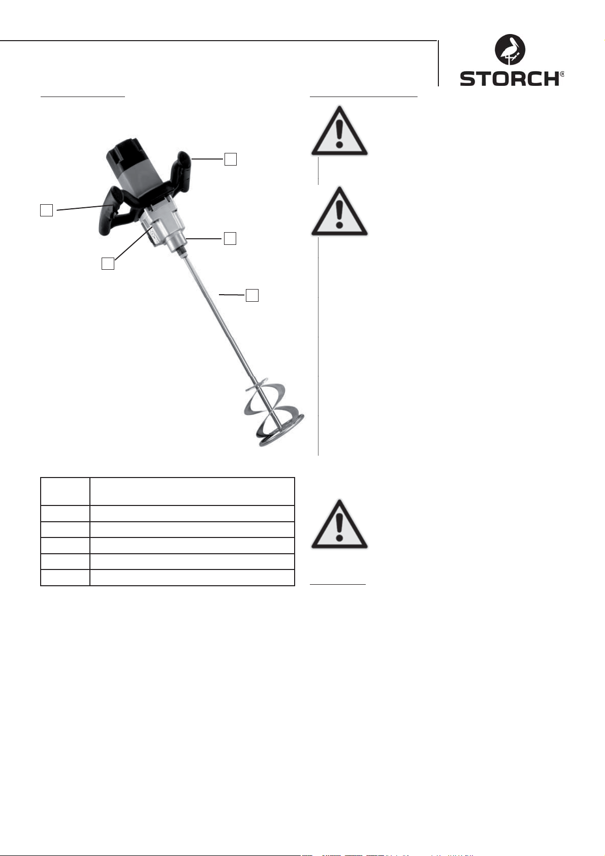
Přehled přístroje
2
1
Bezpečnostní pokyny
Respektujte tento symbol, který
upozorňuje na důležité pokyny a informace. Znamená POZOR!!!
4
3
5
Pozor!
Pozor!
pokyny a respektujte upozornění na nebezpečí a
výstrahy. Přístroj používejte jen k určenému účelu
použití. Nerespektování může mít za následek
poškození přístroje nebo dokonce úrazy. Na přístroji
neprovádějte žádné konstrukční změny!
Přístroj před každým použitím zkontrolujte.
Proveďte kontrolu odborného připojení pohy-•
blivých částí.
Před zapojením zástrčky do zásuvky vypněte •
spínač/vypínač do polohy Vyp
Zkontrolujte kabel, není-li poškozen.•
Zkontrolujte, nejsou-li rozbité některé části.•
Jde o vaši bezpečnost.
Všechny bezpečnostní pokyny a informace si přečtěte a dodržujte je.
Před uvedením přístroje do provozu si
nejdříve přečtěte celý návod k obsluze, aby byl zajištěn bezpečný provoz.
Přesně dodržujte všechny bezpečnostní
1 Volič rychlosti (u přístroje Quick Mixx
50)
2 Spínač/vypínač s aretací
3 Upínání nástroje
4 Regulace počtu otáček
5 Šroubovice míchadla (volitelně)
bez obr. Montážní klíč (přiložen)
Přístroji věnujte potřebnou péči. Abyste mohli zajistit co nejvyšší bezpečnost a optimální výkon udržujte
přístroj vždy čistý.
Přístroj nikdy nepoužívejte v blízkosti •
hořlavých tekutin, par nebo plynů.
Přístroj chraňte před vlhkostí a •
deštěm.
Pozor!
Za provozu
Při míchání suchých materiálů se může uvolňovat •
prach. Na ochranu zdraví musí být pracoviště
řádně větráno a pracovníci musí vždy nosit ochrannu dýchací masku a ochranné brýle. Respektujte
bezpečnostní pokyny výrobce materiálu.
Nenoste volný pracovní úbor ani šátky či šperky •
(prsteny, náramkové hodinky). Ty by mohly být
zachyceny otáčejícími se díly. Noste ochranné
rukavice.
49
Page 50
ZA PROVOZU
Tyto bezpečnostní pokyny si uschovejte
Nedovolte, aby rutina (v důsledku
Elektrické požadavky ve vztahu k motoru
častého používání míchadla) způsobila
chyby z nedbalosti. Nepozornost na
pouhý zlomek sekundy může mít za následek těžké úrazy.
Pozor!
POZOR: Použijte správně zapojený proudový okruh, aby se riziko plynoucí z elektrických nebezpečí, nebezpečí požáru
a poškození nástroje minimalizovalo.
Přístroj je z výroby konstruován na výše
Vydává-li přístroj nezvyklý hluk nebo silné vib-•
race, okamžitě přerušte práci. Přístroj vypněte.
Vytáhněte zástrčku síťového kabelu ze zásuvky.
Přístroj neuvádějte do provozu, není-li závada
nalezena a odstraněna.
Všechny návštěvníky, diváky a děti držte • v
Pozor!
uvedené napětí. Přístroj připojte k elekt-
rické síti s napětím odpovídajícím modelu
a s odbočkou vedení 16 A. Použijte pomalou pojistku
na 16 A nebo jistič. Opotřebovaný, proříznutý nebo
jinak poškozený síťový kabel ihned vyměňte, aby se
snížilo riziko úrazu elektrickým proudem a požáru.
dostatečné vzdálenosti od nástorje a pracoviště.
Elektrické připojení
Před vypnutím přístroje: běžící přístroj nenechávejte nikdy v chodu bez dozoru.
Přístroj vypněte.•
Počkejte, až se všechny pohyblivé části úplně •
zastaví (stav klidu).
Vytáhněte zástrčku síťového kabelu ze zásuvky.•
Za provozu elektrických zařízení mohou být vymrštěny
Zástrčka musí být připojena do vhodné uzemněné
zásuvky, řádně instalované a zapojené
v souladu s místními zákony a předpisy.
Na zástrčce neprovádějte žádné změny.
Jestliže dodaná zástrčka neodpovídá
zásuvkám, nechte si kvalifikovaným
Upozornění
elektrikářem instalovat odpovídající
vhodnou zásuvku.
částečky, které mohou zasáhnout oči uživatele, což
může mít za následek vážná poranění očí. Před uvedením přístroje do chodu si vždy nasaďte ochranné brýle s bočnicemi a v případě potřeby použijte
ochranný štít na celý obličej. Přes korekční nebo
standardní ochranné brýle doporučujeme nosit brýle
s úplným výhledem s ochrannými bočnicemi.
Neodborné připojení může vést k zasažení elektrickým proudem. Vodič kabelu se zelenou izolací a
se žlutým proužkem nebo bez něj je ochranný vodič.
Jestliže je třeba opravit nebo vyměnit zástrčku nebo
síťový kabel, ochranný vodič nesmí být připojen k vedení přívodu s napětím.
Dílnu zajistěte tak, aby byla bezpečná
pro děti
• Dílnu zamykejte
• Vypněte hlavní spínač
Pozor!
• Přístroj uložte na místo nepřístupné
dětem a osobám, které nejsou kvalifiko-
vány k jeho použití.
Jestliže je síťový kabel opotřebovaný, proříznutý nebo
jinak poškozený, musí ho kvalifikovaný elektrikář ihned vyměnit. Jestliže neporozumíte správně pokynům
ohledně uzemnění nebo máte pochybnosti o správném uzemnění přístroje, nechte přístroj zkontrolovat
kvalifikovaným elektrikářem nebo servisní stanicí
STORCH.
Dbejte, aby během zapojování nebo
vytahování zástrčky ze zásuvky nedošlo
ke kontaktu prstů s přívody zástrčky,
omezíte tak riziko úrazu elektrickým
Pozor!
proudem, který může mít i smrtelné
následky.
50
Page 51
Při nesprávném uzemnění může tento přístroj
způsobit úraz elektrickým proudem. To platí zejména
při použití ve vlhkých prostorách, v blízkosti potrubí
nebo ve volné přírodě. Při úrazu elektrickým proudem hrozí i sekundární rizika například v důsledku
kontaktu ruky s míchadlem.
Bezpečnost motoru
Důležité: Aby nedošlo k poškození motoru, musí být
motor často čištěn vyfukováním nebo vysáváním,
aby usazené nečistoty a prach nebránily dobrému
větrání motoru.
Vybalení a kontrola rozsahu dodávky
Vybalení
Ke snížení nebezpečí poranění
neočekávaným náběhem nebo ke
snížení nebezpečí úrazu elektrickým
proudem během vybalování a montáže
Pozor!
nezapojujte zástrčku do zásuvky elekt-
rické sítě. Síťový kabel musí být během
práce na zařízení vždy odpojený ze síťové zásuvky.
Přístroj se dodává kompletní v krabici.
Přístroj připojte k elektrické síti s napětím odpoví-1.
dajícím modelu a s odbočkou vedení 16 A jištěnou
pomalou pojistkou na 16 A nebo s jističem.
Jestliže se motor nespustí, spínač ihned přepněte 2.
do polohy "OFF" (Vyp) a vytáhněte zástrčku kabelu přístroje ze zásuvky elektrické sítě.
Dojde-li během míchání k náhlému zabloko-3.
vání motoru, pusťte spínač a vytáhněte zástrčku
síťového kabelu ze zásuvky. Motor lze opět spustit.
K častému vyhoření pojistky nebo vypnutí 4.
jističe může docházet z následujících důvodů:
a) Motor je přetížený - přetížení se může
vyskytnout, jestliže doplňujete materiál
příliš rychle nebo se přístroj během krátké doby příliš častokrát zapíná a vypíná.
b) Síťové napětí smí překračovat nebo nedosahovat jmenovité napětí uvedené na typovém
štítku max. o 10 %. Při těžkém zatížení musí
napětí motorového přívodu přesně odpovídat
napětí uvedenému na modelu.
Většina poškození motoru bývá následkem 5.
volných nebo vadných spojů, přetížení a příliš
nízkého napětí(například příliš malý průřez vedení v síti) nebo nadměrně dlouhého vedení v
přívodním obvodu. Jestliže motor neběží bez
poruch, vždy zkontrolujte spoje, zatížení a obvod
přívodů. Průřez vodičů nesmí být menší než 2,5
mm².
Přístroj a všechny volné díly vyjměte z kartonu.•
Všechny díly uspořádejte na bezpečnou, stabilní •
pracovní plochu a přístroj podrobně a pozorně
prohlédněte.
Před zahájením montáže zkontrolujte
všechny části, zda jsou úplné. Pokud by
některý díl chyběl, nástroj nemontujte.
Zkontrolujte obaly, zda v nich nezůstal
Upozornění
chybějící díl. Na konci tohoto návodu se
nachází úplný kusovník. Pomocí tohoto
seznamu zjistíte číslo chybějícího dílu.
Pokud by některé díly chyběly, je
zakázáno elektrické míchadlo uvádět do
provozu, dokud nebudou chybějící díly
nahrazeny. Jinak může dojít k těžkým
Pozor!
úrazům.
51
Page 52
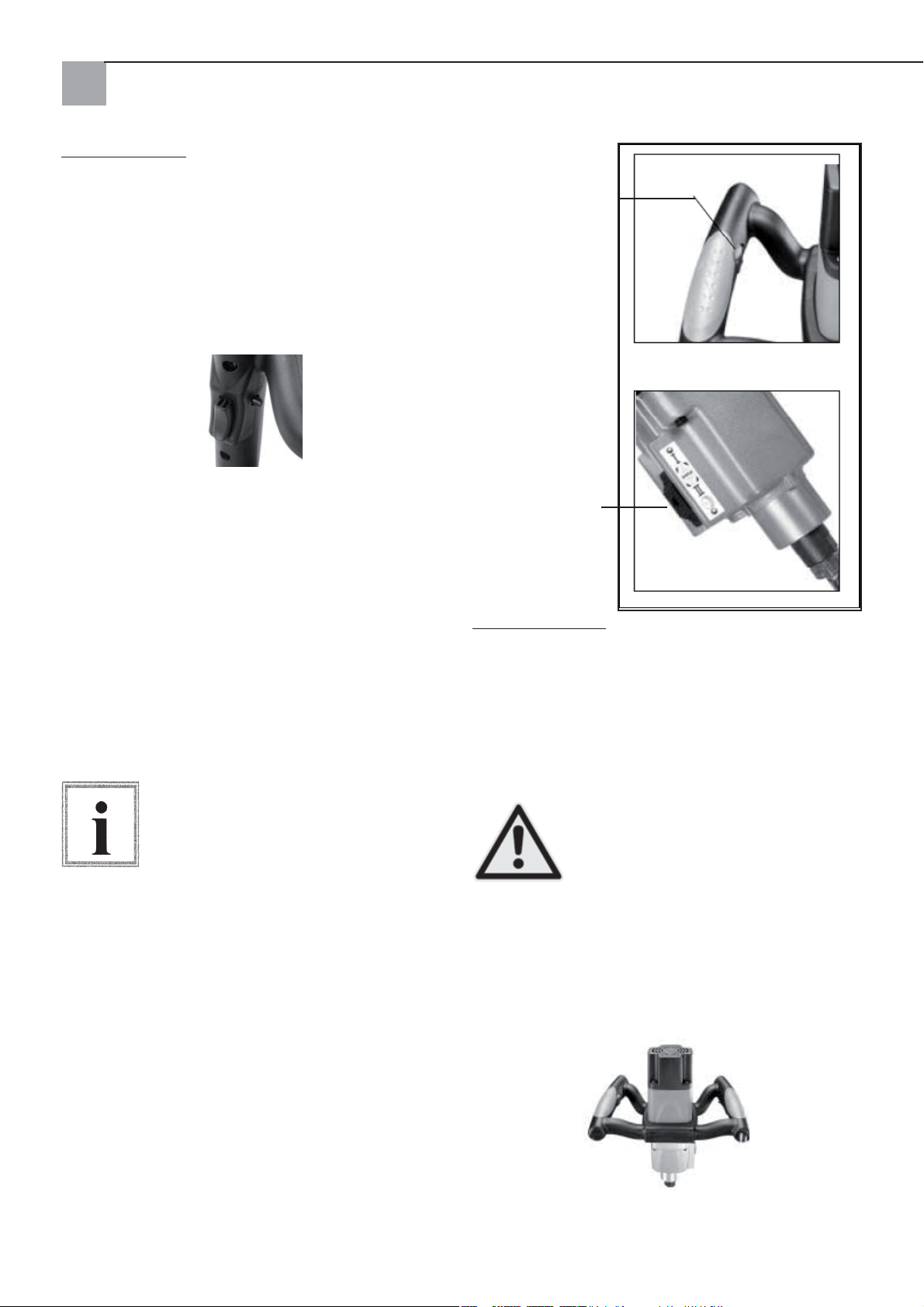
Základní funkce
Spínač/vypínač
Spínač/vypínač - Ke spuštění zařízení stiskněte
spínač. K vypnutí motoru spínač pusťte. Tento nástroj
je vybaven aretačním knoflíkem. Při trvalém provozu
stiskněte spínač a aretační knoflík. Chcete-li přístroj
vypnout, znovu stiskněte spínač a poté ho pusťte.
Nastavení počtu otáček
K dosažení nejlepšího výkonu při míchání určitého
míchaného materiálu lze počet otáček elektronicky
nastavit otáčením stavěcího kolečka palcem. Obr.1.
Změna rychlosti
Míchadlo Quick Mixx 50 je na skříni pohonu vybaveno
přepínačem rychlostí. Je-li míchaný materiál vysoce
viskózní, zvolte nižší počet otáček. Před nastavením
rozsahu otáček zařízení vypněte. Volič rychlosti
stiskněte proti síle pružiny a k výběru požadovaného
rozsahu počtu otáček posuňte volič nahoru resp.
dolů. Dbejte, aby volič správně zacvaknul na místo.
Lehké otočení vřetena rukou usnadňuje úplné zapojení rychlosti. Obr.2
Před změnou rychlosti zařízení vypněte
(OFF).
Upozornění
Regulace počtu otáček
Obr. 1
Přepínání rychlostí
(jen Quick Mixx 50)
Obr. 2
Základní obsluha
Oblasti použití
K účinné kontrola tohoto nástroje je třeba obouruční
obsluha s maximální ochranou a stabilitou při náběhu
a provozním krouticím momentu. Aby nedošlo ke
ztrátě kontroly a tím případnému úrazu, držte zařízení
vždy správně a bezpečně oběma rukama. Na ochranu před poraněním očí používejte ochranné brýle.
Síťový kabel za obsluhou a před pra-
covní oblastí mějte v dostatečné vzdá-
lenosti tak, aby se kabel nemohl na-
Pozor!
motat do míchadla.
Rukojeti
Měkké rukojeti míchadla jsou konstruovány k optimálnímu uchopení. Umožňují obsluze používat
zařízení bez únavy i po delší dobu.
52
Page 53
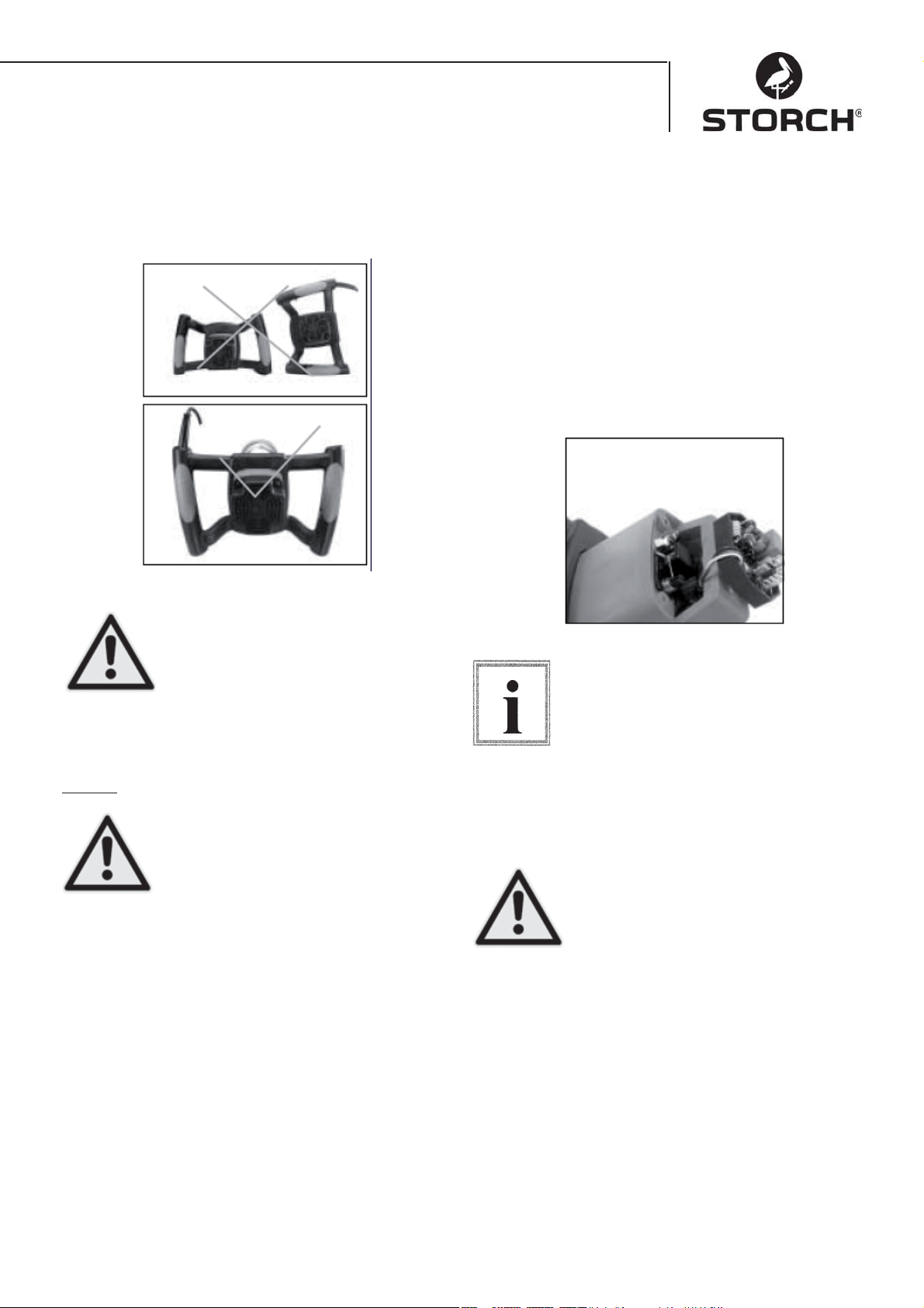
Poloha rukojetí při pokládání
Při odkládání elektrického míchadla postupujte opatrně. Dbejte na správnou polohu rukojetí při
odložení zařízení.
Výměna uhlíkových kartáčů
Oba uhlíkové kartáče vyměňte při opotřebení na délku 7 mm. Před prováděním kontroly nebo výměny
uhlíkových kartáčů nejdříve vždy vytáhněte zástrčku
síťového kabelu zařízení ze zásuvky. Povolením
čtyř šroubů odšroubujte skříň motoru. Pro uvolnění
pnutí stáhněte pera uhlíkových kartáčů zpět. Povolte
šroub, který drží vedení uhlíkového kartáče. Vyjměte
uhlíkový kartáč.
Provedený postup opakujte na druhé straně. Při
zpětné montáži postupujte v opačném pořadí kroků.
Oka na kovové straně jednotky kartáče se zasunou
do stejného otvoru, do kterého lze vložit i uhlíkové
díly.
Nesprávné pokládání nástroje na podlahu (napřklad s kabelem směrem
dolů) může dojít k poškození síťového
kabelu a tím ke zvýšení rizika úrazu
elektrickým proudem a zvýšení rizika
Pozor!
poškození nástroje.
Údržba
Před údržbou zařízení vytáhněte
zástrčku z elektrické sítě. Tím se sníží
riziko úrazů v důsledku neočekávaného
naběhnutí stroje a úrazů elektrickým
Pozor!
proudem.
Nástroj udržujte vždy čistý. Odstraňujte prach
nastřádaný na pohyblivých částech. Dbejte, aby
nástroj pracoval správně. Pravidelně kontrolujte pevné usazení šroubů a čepů.
Čištění míchadla
Všechny větrací otvory pravidelně vždy po 50 hodinách provozu vyfoukejte stlačeným vzduchem.
Všechny plastové díly pravidelně čistěte měkkým,
vlhkým hadříkem. Plastové díly NIKDY nečistěte
rozpouštědly.
Při práci se stlačeným vzduchem používejte ochranné
brýle. Po každých 200 provozních hodinách nechte
kvalifikované servisní stanicí firmy STORCH vyměnit
mazivo v převodové skříni.
Při nasazování stejných kartáčů se
nejdříve přesvědčte, že je nasazujete
stejně, tak jak jste je vyjmuli. V opačném
případě se může důsledkem doby záběhu
Upozornění
snížit výkon motoru a zvýšit opotřebení
kartáčů. Doporučujeme provést alespoň
jednou ročně úplné vyčištění a promazání
přístroje v některém z oprávněných zákaznických
středisek STORCH.
Aby byla zajištěna bezpečnost a spolehlivost, je vhodné přenechat všechny
opravy (s výjimkou výměny uhlíkových
kartáčů, které jsou přístupné zvenčí)
oprávněnému zákaznickému servis-
Pozor!
nímu středisku STORCH.
53
Page 54
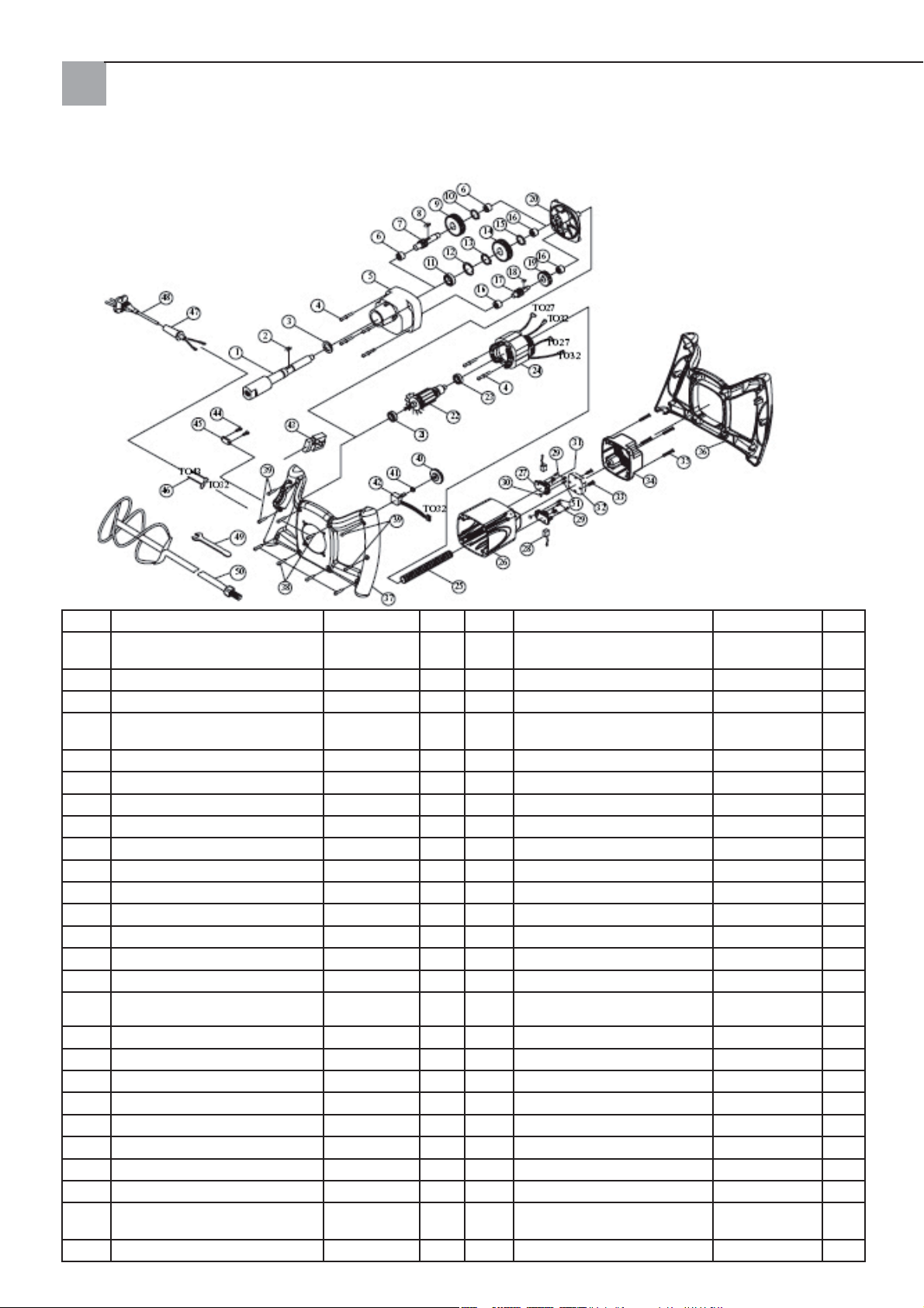
Kusovník Quick Mixx 25
Číslo Označení Ks. Číslo Označení Ks.
1 VŘETENO M14xP2.0 1 27 DRŽÁK UHLÍKOVÉHO
2 PRUŽNÝ KLÍN 5 x 5 x 12 1 28 UHLÍKOVÝ KARTÁČ 2
3 TĚSNĚNÍ 22x32x7 1 29 ŠROUB M4x12 4
4 ŠROUB VČETNĚ PÉROVÉ
PODLOŽKY
5 PŘEVODOVÁ SKŘÍŇ 1 1 31 PRUŽINA 2
6 JEHLOVÉ LOŽISKO HK1010 2 32 SNÍMAČ S EMV 230 V 1
7 PASTORKOVÝ HŘÍDEL 10T-080 1 33 ŠROUB M4x25 2
8 PRUŽNÝ KLÍN 5x5x10 1 34 KRYT MOTORU 1
9 PŘEDLOHOVÉ KOLO 30T 1 35 ŠROUB M5x20 4
10 POJISTNÝ KROUŽEK S-12 1 36 DRŽADLO (NAHOŘE) 1
11 LOŽISKO 6003ZZ 1 37 DRŽADLO (DOLE) 1
12 POJISTNÝ KROUŽEK R-35 1 38 ŠROUB M4X20
13 POJISTNÝ KROUŽEK S-17 1 39 ŠROUB M4X25 4
14 OZUBENÉ KOLO 34T 1 40 KOLO K NASTAVENÍ OTÁČEK 1
15 POJISTNÝ KROUŽEK S-15 1 41 ŠESTIHRANNÁ MATICE 1/4“X34 1
16 JEHLOVÉ LOŽISKO HK0810 3 42 ELEKTRONICKÉ NASTAVENÍ
17 PASTORKOVÝ HŘÍDEL 14T 1 43 SPÍNAČ 8301 230 V 1
18 PRUŽNÝ KLÍN 4X4X8 1 44 ŠROUB M4X14 2
19 PŘEDLOHOVÉ KOLO 37T 1 45 KABELOVÁ SPONA 1
20 KRYT PŘEVODOVKY 1 46 KABEL 16AWG 2
21 LOŽISKO 609 2RS 1 47 OCHRANA KABELU 1
22 KOTVA 230V 1 48 SÍŤOVÝ KABEL 230V 1
23 LOŽISKO 608ZZ 1 49 KLÍČ NA ŠROUBY M22 1
24 STATOR 230V 1 50 SPIRÁLOVÉ MÍCHADLO 1
25 OCHRANNÁ TRUBICE NA
KABEL
26 TĚLESO MOTORU 1
M5x60 6 30 ŠESTIHRANNÁ MATICE M4 2
M8 1 51 ŠROUB M4x10 2
54
KARTÁČE
POČTU OTÁČEK.
B100K
2
1
Page 55
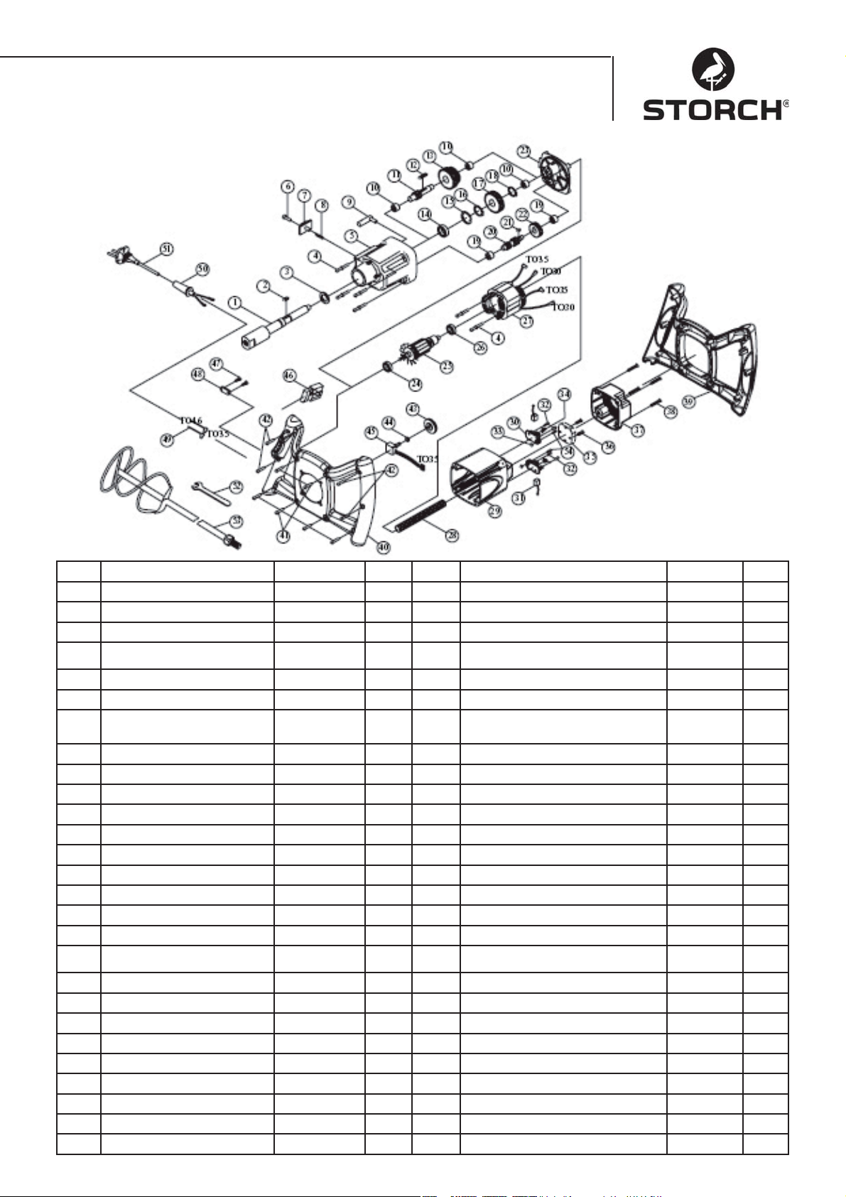
Kusovník Quick Mixx 50
Číslo Označení Kusy Číslo Označení Kusy
1 VŘETENO M14xP2.0 1 28 OCHRANNÁ TRUBICE NA KABEL M8 1
2 PRUŽNÝ KLÍN 5 x 5 x 12 1 29 TĚLESO MOTORU 1
3 TĚSNĚNÍ 2 x 32 x 7 1 30 DRŽÁK UHLÍKOVÉHO KARTÁČE 2
4 ŠROUB VČETNĚ PÉROVÉ
5 PŘEVODOVÁ SKŘÍŇ 1 32 ŠROUB M4X12 4
6 ŠROUB S DRÁŽKOU 1 33 ŠESTIHRANNÁ MATICE M4 2
7 POSUVNÝ SPÍNAČ K
8 PRUŽINA
9 ŘADICÍ VIDLICE 1 36 ŠROUB M4x25 2
10 JEHLOVÉ LOŽISKO HK1010 3 37 KRYT SKŘÍNĚ MOTORU 1
11 PASTORKOVÝ HŘÍDEL 10T-130 1 38 ŠROUB M5x20 4
12 PRUŽNÝ KLÍN 5 x 5 x 45 1 39 DRŽADLO (NAHOŘE) 1
13 PŘEDLOHOVÉ KOLO 30T&34T 1 40 DRŽADLO (DOLE) 1
14 LOŽISKO 6003ZZ 1 41 ŠROUB M4x20 6
15 POJISTNÝ KROUŽEK R-35 1 42 ŠROUB M4x25 4
16 POJISTNÝ KROUŽEK S-17 1 43 KOLO K NASTAVENÍ OTÁČEK 1
17 OZUBENÉ KOLO 34T 1 44 ŠESTIHRANNÁ MATICE 1/4“x34 1
18 POJISTNÝ KROUŽEK S-15 1 45 ELEKTRONICKÉ NASTAVOVÁNÍ
19 JEHLOVÉ LOŽISKO HK0810 2 46 SPÍNAČ 8301 1
20 PASTORKOVÝ HŘÍDEL 14T&10T 1 47 ŠROUB M4x14 2
21 PRUŽNÝ KLÍN 4x4x8 1 48 KABELOVÁ SPONA 1
22 PŘEDLOHOVÉ KOLO 37T 1 49 KABEL 16AWG 2
23 KRYT PŘEVODOVKY 1 50 VÝZTUŽ KABELU 1
24 LOŽISKO 609 2RS 1 51 SÍŤOVÝ KABEL 230V 1
25 KOTVA 230V 1 52 KLÍČ NA ŠROUBY M22 1
26 LOŽISKO 608ZZ 1 1 53 SPIRÁLOVÉ MÍCHADLO 1
27 STATOR 230V 1 54 ŠROUB M4x10 2
PODLOŽKY
VOLBĚ PŘEVODOVÉHO
STUPNĚ
M5x60 6 31 UHLÍKOVÝ KARTÁČ 2
1 34 PRUŽINA 2
Ø6x0.6x4
1 35 SNÍMAČ S EMV 230 V 1
POČTU OTÁČEK
B100K 1
55
Page 56

ES - prohlášení o shodě
Prohlašujeme ve vlastní odpovědnosti, že výrobek
typu: Quick Mixx 25, Quick Mixx 50
na který se vztahuje toto prohlášení, odpovídá následujícím normám a normativním
dokumentům:
VDE 0740 - 1 : 2003-12
DIN EN 50144-1 : 2003-11
V souladu s ustanoveními směrnic 98/37/EHS, 73/23/EHS, 89/336/EHS.
STORCH
Malerwerkzeuge & Profigeräte GmbH
Platz der Republik 6-8
D-42107 Wuppertal
Jörg Heinemann – jednatel
56
Page 57
SK
Srdečná vďaka
za Vašu dôveru k firme STORCH. Kúpou ste sa rozhodli pre kvalitný výrobok.
Ak by ste mali napriek tomu návrhy na zlepšenie alebo snáď nejaký problém, tak sa budeme veľmi tešiť,
keď budeme o Vás počuť. Porozprávajte sa prosím s
Vašim pracovníkom služby zákazníkom alebo v naliehavých prípadoch aj priamo s nami.
S priateľským pozdravom
Servisné oddelenie firmy STORCH
Tel. +49 (0)2 02 . 49 20 - 112
Fax +49 (0)2 02 . 49 20 - 111
Obsah strana
Technické údaje 57
Rozsah dodávky 57
Prehľad prístroja 58
Bezpečnostné pokyny 58
Elektrická prípojka 59
Základné funkcie 61
Základné ovládanie 61
Čistenie miešačky 62
Kusovník Quick Mixx 25 63
Kusovník Quick Mixx 50 64
Technické údaje
Quick Mixx 25 Quick Mixx 50
Napätie 230V / 50Hz 230V / 50Hz
Vstupný výkon 1100 Watt 1300 Watt
Výstupný vý-
kon (N-m)
Počet pre-
vodových
stupňov
Otáčky naprázdno
Istenie Trieda 2 Trieda 2
Závit spojky M14 M14
Miešacia tyč
max. priemer
Elektronické
riadenie
otáčok
Hmotnosť 3,6 kg 4,1 kg
Rozsah dodávky
Miešačka, montážny kľúč, návod na obsluhu
13,5 14,7
12
250~700 1. prevodo-
vý stupeň
150~400
2. prevodový stupeň
250~700
120 mm 140 mm
Áno Áno
57
Page 58
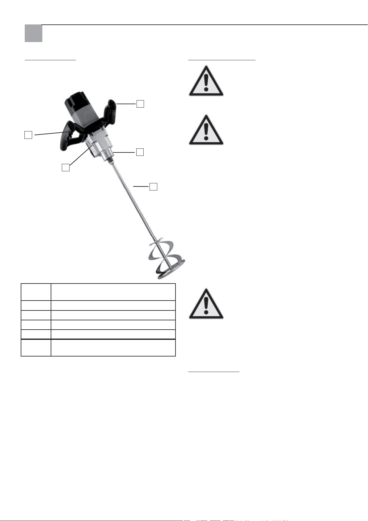
Prehľad prístroja
2
1
Bezpečnostné pokyny
Dávajte pozor na tento symbol, ktorý
upozorňuje na dôležité bezpečnostné
pokyny. Znamená POZOR!!!
Ide o vašu bezpečnosť.
4
3
5
Pozor!
Prečítajte si prosím všetky bezpečnostné
pokyny a pokyny pre obsluhu a
dodržiavajte ich. Pred uvedením prístroja do prevádzky si prosím prečítajte
Pozor!
Dodržiavajte presne všetky bezpečnostné pokyny,
upozornenia na nebezpečenstvo a výstražné upozornenia. Prístroj používajte iba na plánované účely
použitia. Nedodržiavanie môže viesť ku škodám na
prístroji alebo dokonca ku telesným poraneniam.
Neuskutočňujte žiadne konštrukčné zmeny na
prístroji!
Prístroj pred každým použitím skontrolujte.
kompletný návod na obsluhu, aby
ste zaručili bezpečnú prevádzku.
1 Voličový prepínač prevodových stupňov
(pri Quick Mixx 50)
2 Zapínač / vypínač so zaistením
3 Uchytenie nástroja
4 Regulácia otáčok
5 Miešacia špirála (alternatívne)
horný
obr.
Montážny kľúč (súčasne dodaný)
Skontrolujte odborné pripojenie pohyblivých die-•
lov.
Pred zastrčenímm sieťovej zástrčky prepnite •
zapínač /vypínač na vyp
Skontrolujte poškodené káble.•
Skontrolujte polámané časti.•
Prístroj ošetrujte so starostlivosťou.
Nástroj udržiavajte čistý, aby bolo možné
zaručiť čo najmenšiu možnú bezpečnosť
a optimálny výkon.
Pozor!
Prístroj nepoužívajte nikdy v blízkosti horľavých •
kvapalín, výparov alebo plynov.
Chráňte pred vlhkosťou a dažďom.•
Počas prevádzky
Pri namiešaní suchého tovaru môže vzniknúť •
prach. Kvôli ochrane zdravia sa musí pracovná oblasť dobre odvetrať. Noste vždy masku na ochranu dýchania a ochranné okuliare.
Dodržiavajte bezpečnostné pokyny výrobcu materiálu.
Nenoste žiadne široké oblečenie, šály na krku, •
šperky (prstene, náramkové hodiny).
Tieto by sa mohli zachytiť otáčajúcimi sa časťami.
Noste ochranné rukavice.
58
Page 59
Pri bežiacom stroji
Tieto bezpečnostné pokyny si uschovajte.
Nedovoľte, aby rutina (v dôsledku častého používania
miešačky) viedla k chybám z dôvodu povrchnosti.
Neopatrnosť na zlomky sekúnd môže mať za následok ťažké poranenia.
V prípade, že nástroj robí neobvyklý •
hluk alebo silne vibruje, prácu ihneď
prerušte. Nástroj vypnite. Vytiahnite
sieťovú zástrčku. Neuvádzajte do pre-
Pozor!
vádzky skôr, ako bola chyba nájdená a
odstránená.
Držte mimo dosahu nástroja a pracoviska •
všetkých návštevníkov, prizera júcich sa a deti.
Pred odstavením nástroja: bežiaci nástroj nenechávajte nikdy bez dohľadu
• Vypnite prístroj,
• Počkajte, kým sa zastavia všetky pohyblivé
časti,
• Vytiahnite sieťovú zástrčku.
Prevádzkou elektrických nástrojov sa môžu vymrštiť
cudzie telesá do vašich očí, čím môže dôjsť k
závažným poraneniam očí. Pred uvedením nástroja do prevádzky si vždy založte ochranné okuliare
s bočnou ochranou a v prípade potreby ochranu celej tváre. Odporúčame panoramatické okuliare na
nosenie cez korekčné okuliare alebo štandardné
bezpečnostné okuliare s bočnou ochranou.
Dielňu vytvorte tak, aby bola bezpečná pre deti
• Dielňu uzamykajte
• Vypnite hlavný vypínač
• Nástroj uschovajte na mieste
neprístupnom pre deti a iné osoby nekvalifikované na používanie nástroja.
Pozor!
Požiadavky vztiahnuté na motor a elektrický prúd
POZOR: Používajte odbornú ochranu elektrického okruhu, aby sa
znížilo riziko týkajúce sa elektrických
nebezpečenstiev, nebezpečenstvo
Pozor!
požiaru alebo poškodenia nástroja.
Nástroj je dimenzovaný zo strany výroby na prevádzku s hore uvedeným napätím. Pripojte nástroj na sieťové vedenie so zodpovedajúcim napätím a 16 ampérovým odbočným vedením.
Použite pomalú 16 ampérovú poistku alebo ochranný
spínač. Opotrebovaný, odrezaný alebo v akejkoľvek
forme poškodený sieťový kábel treba bezodkladne
vymeniť, aby sa znížilo nebezpečenstvo zásahu elektrickým prúdom alebo požiaru.
Elektrická prípojka
Zástrčka sa musí pripojiť na vhodnú, uzemnenú zásuvku namontovanú
podľa miestnych zákonov a predpisov.
Neuskutočňujte žiadne zmeny na dodanej zástrčke. V prípade, že dodaná
Upozornenie
zástrčka sa nehodí do zásuvky, treba
inštalovať vhodnú zásuvku prostred-
níctvom kvalifikovaného elektrikára.
Neodborné pripojenie ochranného vodiča môže viesť
k zásahu elektrickým prúdom. Pri žile so zelenou izoláciou s alebo bez žltých pásikov sa jedná o ochranný
vodič. V prípade, že je potrebná oprava alebo výmena
zástrčky alebo sieťového kábla, nesmie byť ochranný
vodič pripojený na prípojku vedúcu elektrický prúd.
V prípade, že je sieťový kábel opotrebovaný, odrezaný
alebo nejakým spôsobom poškodený, musí ho bezodkladne vymeniť odborník elektrikár. V prípade, že neboli úplne pochopené pokyny týkajúce sa uzemnenia
alebo v prípade, že existujú pochybnosti o riadnom
uzemnení nástroja, treba nechať nástroj skontrolovať
prostredníctvom kvalifikovaného odborníka elektrikára alebo servisnej stanice STORCH.
59
Pozor!
Treba dávať pozor na to, aby počas zasúvania alebo ťahania sieťovej zástrčky
neexistoval žiadny kontakt prstov s prípojkami sieťovej zástrčky, aby sa zab-
ránilo nebezpečenstvu poranenia alebo
nebezpečenstvu ohrozenia života vplyvom zásahu elektrickým prúdom.
Page 60
Pri neodbornom uzemnení môže tento
nástroj vyvolať zásah elektrickým prúdom, zvlášť pri používaní vo vlhkých oblastiach, v blízkosti potrubí a na voľnom
priestranstve. V prípade zásahu elekt-
Pozor!
rickým prúdom vzniknú podľa možnosti
sekundárne nebezpečenstvá, napr. kvôli
kontaktu rukou s miešačkou.
Bezpečnosť motora
DÔLEŽITÉ: Kvôli zabráneniu poškodení motora sa
musí tento motor často vyfukovať alebo odsávať,
aby nebolo pravidelne normálne vetranie motora
ovplyvňované prachom.
Pripojte nástroj na elektrickú sieť s napätím zod-1.
povedajúcim modelu a 16 ampérovým odbočným
vedením s pomalou 16 ampérovou poistkou alebo ochranným spínačom.
Keď motor neštartuje, dostaňte spínač bezod-2.
kladne do polohy "OFF" a vytiahnite sieťovú
zástrčku prístroja.
Ak by mal motor počas miešania náhle 3.
blokovať, pustite zapínač a vytiahnite sieťovú
zástrčku nástroja. Motor sa môže teraz znova
naštartovať.
Z nasledujúcich dôvodov môžu poistky často 4.
zareagovať alebo môže vypnúť ochranný vypínač:
a) Motor je preťažený - Preťaženie sa
môže vyskytnúť vtedy, keď sa dopĺňa
príliš rýchlo alebo nástroj v rámci krátkej doby príliš často štartuje a zastavuje sa.
b) Sieťové napätie nesmie prekročiť alebo
nedosiahnuť sieťové napätie podľa typového
štítku o viac ako 10%. Pri ťažkých bremenách
musí napätie existujúce na sieťovej prípojke presne zodpovedať napätiu uvedenému pre model.
Väčšina poškodení motora sa môže odvodiť z 5.
voľných alebo chýbajúcich spojení, preťaženia
alebo príliš nízkeho napätia (napríklad príliš malý
priemer žily v sieti) alebo z nadmerne dlhých žíl
v napájacom obvode. Keď motor nebeží bezchybne, vždy skontrolujte spojenia, bremeno a napájací obvod. Prierez žily nesmie byť menší ako
2,5mm².
Vybalenie a kontrola rozsahu dodávky
Vybalenie
Na zníženie nebezpečenstva poranenia
kvôli neočakávanému spusteniu alebo zásahu elektrickým prúdom počas
vybaľovania a montáže nezapájajte
Pozor!
sieťovú zástrčku do zásuvky. Sieťový
kábel musí počas prác na prístroji zostať
zásadne odpojený od siete.
Prístroj sa dodáva kompletne v jednej škatuli.
Vyberte nástroj a všetky voľné diely zo škatule.•
Všetky diely umiestnite na bezpečnej, nepohy-•
blivej pracovnej ploche a podrobte nástroj starostlivej vizuálnej kontrole.
Pred začiatkom montáže skontrolujte
kompletnosť všetkých dielov. V prípade,
že by mal chýbať jeden diel, nástroj nemontujte. Skontrolujte obalový materiál
na chýbajúce diely. Na konci tohto ná-
Upozornenie
vodu sa nachádza kompletný kusovník.
Pomocou tohto zoznamu zistite číslo
chýbajúceho dielu.
V prípade, že nejaké diely chýbajú, nesmie sa elektircká miešačka uvádzať do
prevádzky, až keď budú nahradené chýbajúce diely. V opačnom prípade môže
Pozor!
dôjsť k ťažkým poraneniam.
60
Page 61
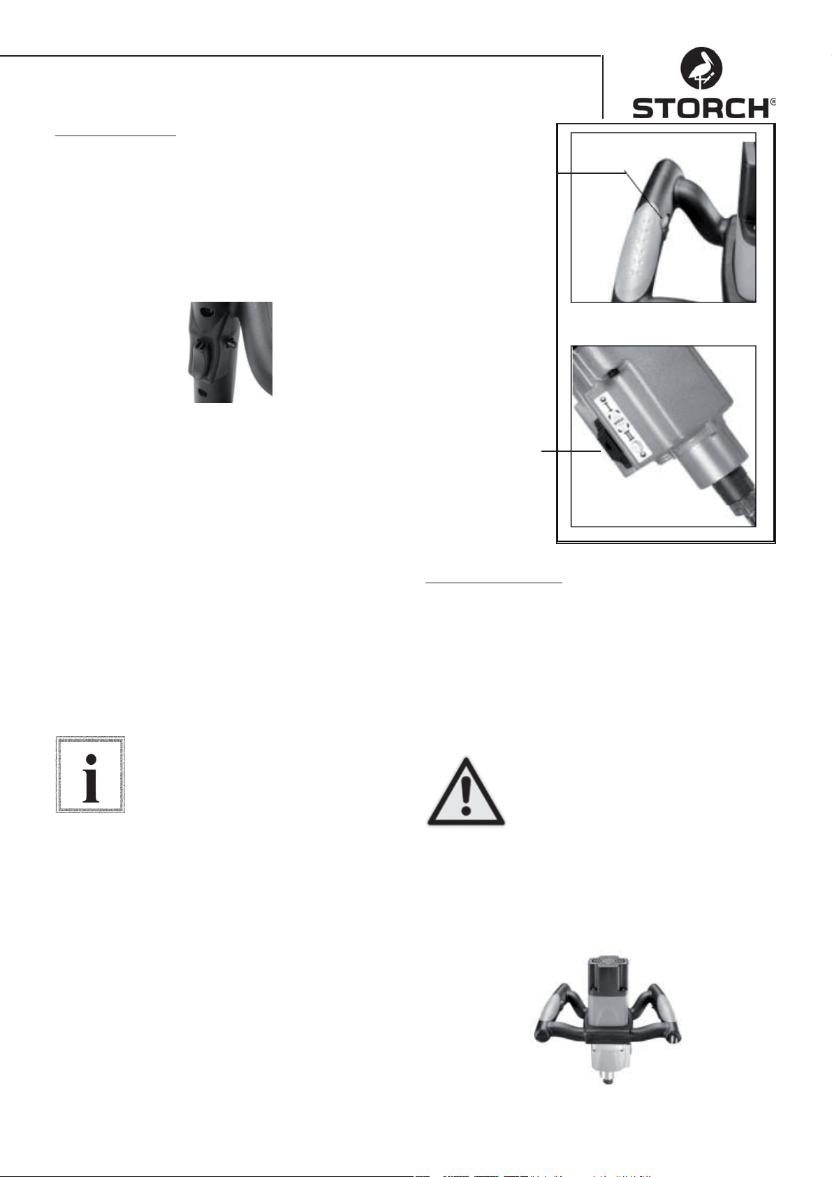
Základné funkcie
Zapínač / vypínač
Zapínač/vypínač - Na naštartovanie nástroja stlačte
zapínač. Na vypnutie motora zapínač pustite. Tento nástroj je vybavený zaisťovacím gombíkom. Pre
trvalú prevádzku stlačte zapínač a stlačte zaisťovací
gombík. Na vypnutie znova stlačte zapínač a potom
ho pustite.
Nastavenie otáčok
Pre lepší miešací výkon pri určitom miešanom materiáli sa môžu nastaviť otáčky elektronicky otočením
nastavovacieho kolieska s palcami. Obr.1.
Zmena prevodového stupňa
Miešačka Quick Mixx 50 je vybavená na telese prevodovky voličovým prepínačom prevodových stupňov.
Pre vysoko viskózny materiál zvoľte nižšie otáčky.
Pred nastavovaním rozsahu otáčok prístroj vypnite.
Stlačte voličový prepínač prevodových stupňov proti
napnutiu pružiny a na výber želaného rozsahu otáčok
ho posuňte smerom hore resp. smerom dole. Dávajte pozor na to, aby voličový prepínač prevodových
stupňov správne zaskočil. Ľahké otočenie vretena
rukou uľahčuje úplné napojenie prevodového stupňa.
Obr. 2
Pred zmenou prevodového stupňa
nástroj prosím vypnite (OFF).
Upozornenie
Regulácia otáčok
Obr. 1
Voličový prepínač
prevodového stupňa
(iba Quick Mixx 50)
Obr. 2
Základné ovládanie
Oblasti použitia
K efektívnej kontrole tohto nástroja je potrebné
obojručné ovládanie pre maximálnu ochranu a stabilitu pri rozbehovom a prevádzkovom krútiacom momente. Aby sa zabránilo strate kontroly a tým und
prípadne vyskytujúcim sa poraneniam, držte prístroj
odborne a bezpečne oboma rukami. Na ochranu pred
poraneniami očí noste ochranné okuliare.
Sieťový kábel držte ďalej za obsluhou a
mimo dosahu pracovnej oblasti, aby ste
zabránili tomu, že sa kábel zapletie s
Pozor!
miešačkou.
Držadlá
Mäkké držadlá miešačky sú dimenzované na optimálne držanie. Obsluhe umožňujú aj pri dlhších
časoch nasadenia prácu bez únavy.
61
Page 62
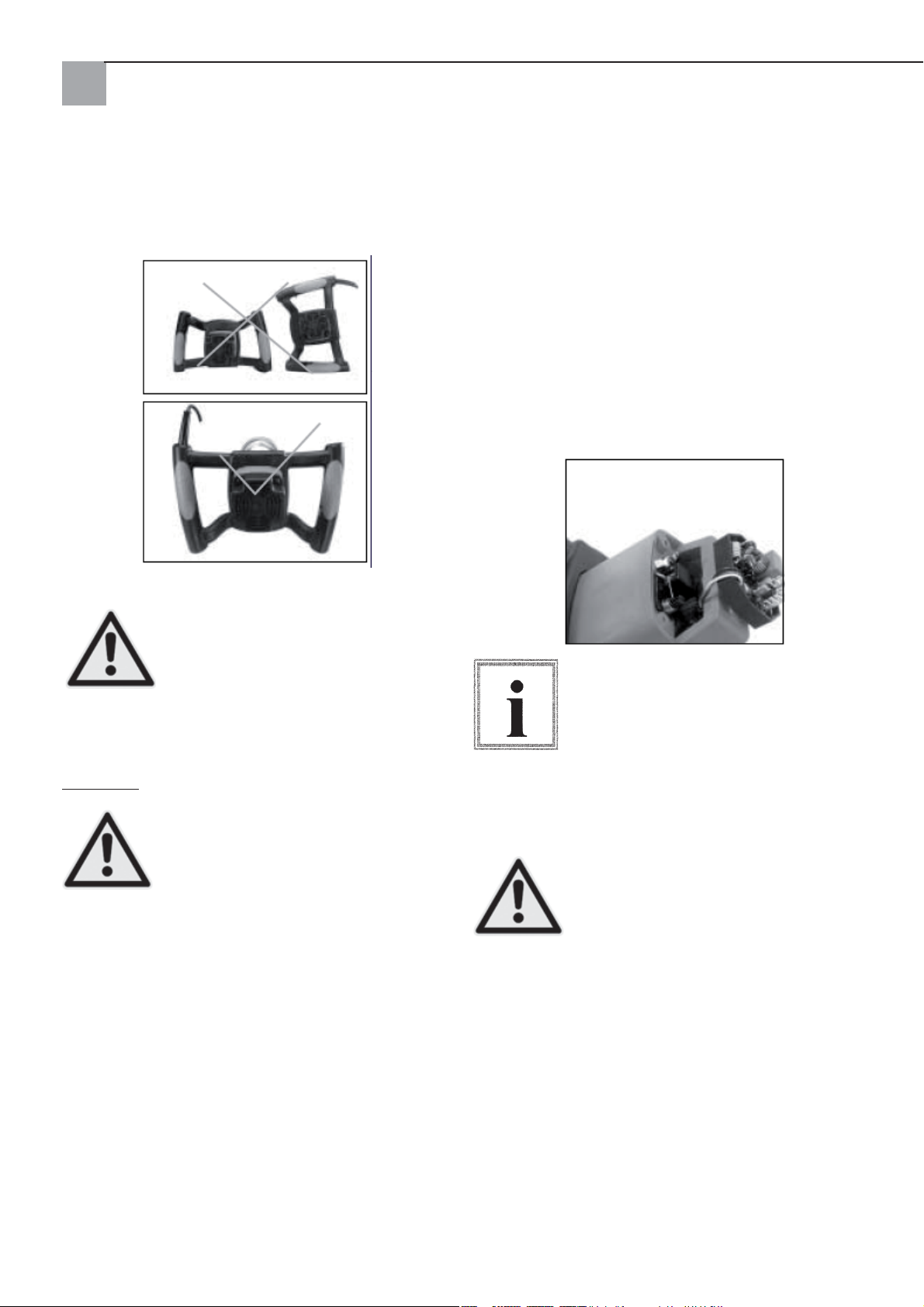
Poloha držadla pri odložení
Pri odkladaní elektrickej miešačky postupujte prosím
opatrne. Dávajte pri odložení pozor na správnu polohu držadiel.
Výmena uhlíkových štetín
Obidve uhlíkové štetiny vymeňte pri opotrebovaní na dĺžku 7 mm. Aby bolo možné skontrolovať
alebo vymeniť uhlíkové štetiny, najprv vytiahnite
sieťovú zástrčku prístroja. Roskrutkujte teleso motora uvoľnením štyroch skrutiek. Pružiny uhlíkových
štetín ťahajte späť, aby bolo možné uvoľniť napätie. Uvoľnite skrutku, ktorá drží vedenie uhlíkových
štetín. Uhlíkovú štetinu vytiahnite.
Postup zopakujte na druhej strane. Pri montáži postupujte v opačnom poradí.
Spojky na strane kovu kefovej jednotky prídu do rovnakého otvoru, do ktorého sa hodia tiež uhlíkové diely.
Neodborné ukladanie nástroja na podlahu (napr. s káblom smerom dole)
môže viesť k poškodeniu sieťového
kábla a tým k zvýšeniu nebezpečenstva
zásahu elektrickým prúdom, ako aj rizík
Pozor!
poškodení na prístroji.
Varovanie
Pred údržbou prístrojov vytiahnite
sieťovú zástrčku, aby sa znížilo riziko
poranení v dôsledku neočakávaného
rozbehu alebo zásahu elektrickým prú-
Pozor!
dom.
Nástroj udržujte čistý. Na pohyblivých častiach
odstráňte nazbieraný prach. Dávajte pozor na to, aby
pracoval nástroj riadne. Pravidelne kontrolujte pevné
osadenie skrutiek a svorníkov.
Čistenie miešačky
Pravidelne vždy po 50 prevádzkových hodinách vyfúknite všetky vetracie štrbiny so suchým stlačeným
vzduchom. Pravidelne čistite všetky plastové diely
s mäkkou, vlhkou handrou. Plastové diely NIKDY
nečistite s čistiacimi prostriedkami.
Pri práci so stlačeným vzduchom noste ochranné
okuliare. Po vždy 200 prevádzkových hodinách treba vymeniť mazací prostriedok v prevodovke u kvalifikovanej servisnej stanici STORCH.
Kvôli nasadeniu tých istých kief sa najprv uistite, že sa kefy nasadia tak isto,
ako boli odobraté. V opačnom prípade
sa môže v dôsledku rozbehovej periódy
znížiť výkon motora a zvýšiť opotrebo-
Upozornenie
vanie kief. Odporúča sa minimálne raz
ročne zariadiť úplne vyčistenie a namazanie prístroja u autorizovaného centra zákazníckeho
servisu firmy STORCH.
Aby bolo možné zabezpečiť istotu a
spoľahlivosť, mali by sa všetky opravy
s výnimkou uhlíkových kief prístupných
zvonka uskutočniť v autorizovanom
Pozor!
centre zákazníckych služieb STORCH.
62
Page 63
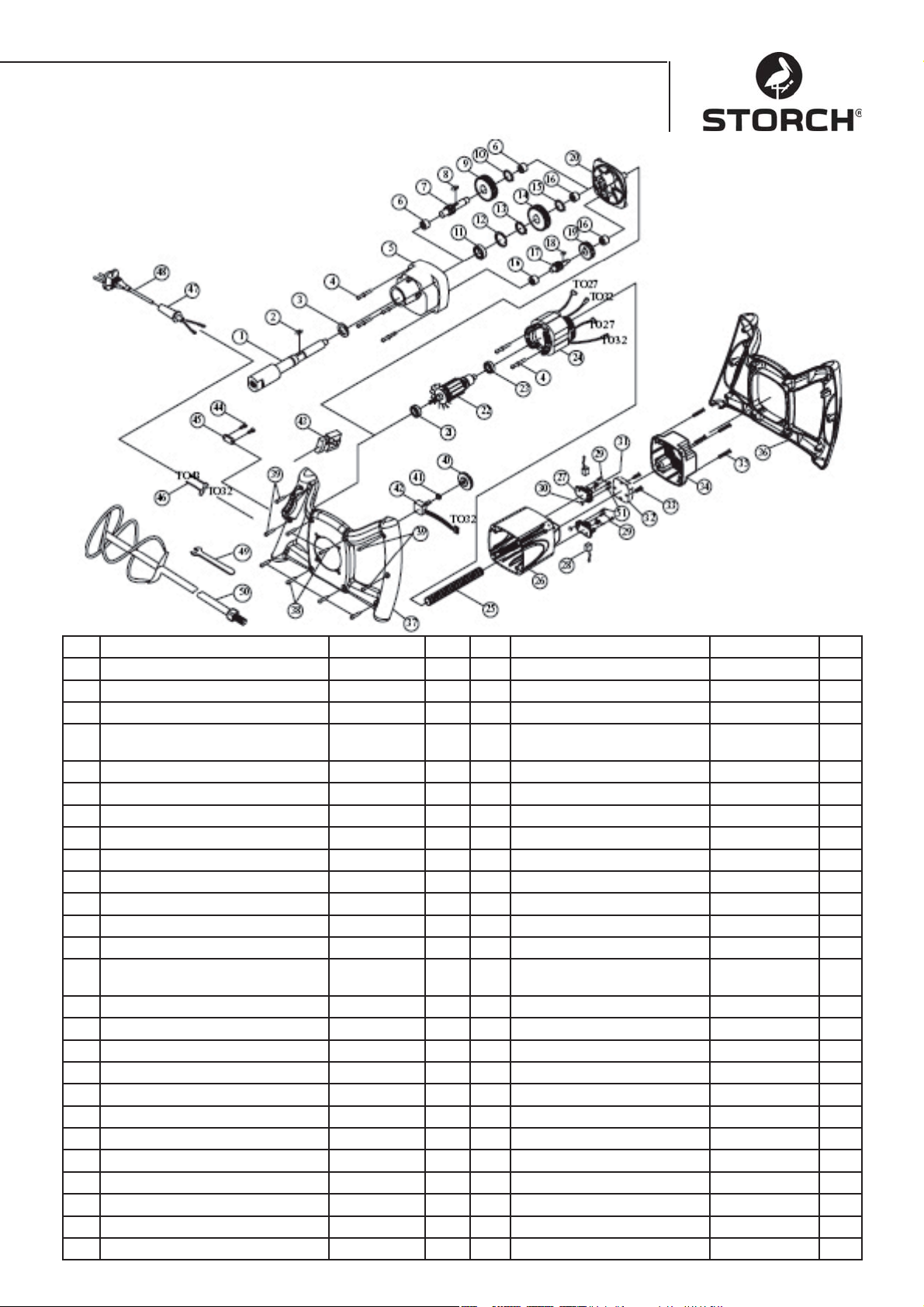
Kusovník Quick Mixx 25
č. Označenie ks č. Označenie ks
1 VRETENO M14xP2.0 1 27 DRŽIAK UHLÍKOVEJ KEFY 2
2 PRUŽNÝ KLIN 5x5x12 1 28 UHLÍKOVÁ KEFA 2
3 TESNENIE 22x32x7 1 29 SKRUTKA M4x12 4
4 SKRUTKA VRÁT. PRUŽNEJ
PODLOŽKY
5 PREVODOVÁ SKRIŇA 1 1 31 PRUŽINA 2
6 IHLOVÉ LOŽISKO HK1010 2 32 SENZOR S EMV 230V 1
7 HRIADEĽ S PASTORKOM 10T-080 1 33 SKRUTKA M4x25 2
8 PRUŽNÝ KLIN 5x5x10 1 34 KRYT MOTORA 1
9 PREDLOHOVÉ KOLESO 30T 1 35 SKRUTKA M5x20 4
10 POISTNÝ KRÚŽOK S-12 1 36 DRŽADLO (HORE) 1
11 LOŽISKO 6003ZZ 1 37 DRŽADLO (DOLE) 1
12 POISTNÝ KRÚŽOK R-35 1 38 SKRUTKA M4X20
13 POISTNÝ KRÚŽOK S-17 1 39 SKRUTKA M4X25 4
14 OZUBENÉ KOLESO 34T 1 40 NASTAVOVACIE KOLIESKO
15 POISTNÝ KRÚŽOK S-15 1 41 ŠESŤHRANNÁ MATICA 1/4“X34 1
16 IHLOVÉ LOŽISKO HK0810 3 42 ELEKTRONICKÉ OTÁČKY
17 HRIADEĽ S PASTORKOM 14T 1 43 PREPÍNAČ 8301 230V 1
18 PRUŽNÝ KLIN 4X4X8 1 44 SKRUTKA M4X14 2
19 PREDLOHOVÉ KOLESO 37T 1 45 KÁBLOVÁ PRÍCHYTKA 1
20 KRYT PREVODOVKY 1 46 KÁBEL 16AWG 2
21 LOŽISKO 609 2RS 1 47 KÁBLOVÁ OCHRANA 1
22 KOTVA 230V 1 48 SIEŤOVÝ KÁBEL 230V 1
23 LOŽISKO 608ZZ 1 49 SKRUTKOVÝ KĽÚČ M22 1
24 STATOR 230V 1 50 ŠPIRÁLOVÁ MIEŠAČKA 1
25 OCHRANNÁ RÚRKA KÁBLA M8 1 51 SKRUTKA M4x10 2
26 TELESO MOTORA 1
M5x60 6 30 ŠESŤHRANNÁ MATICA M4 2
OTÁČOK
NASTAV.B100K 1
63
1
Page 64
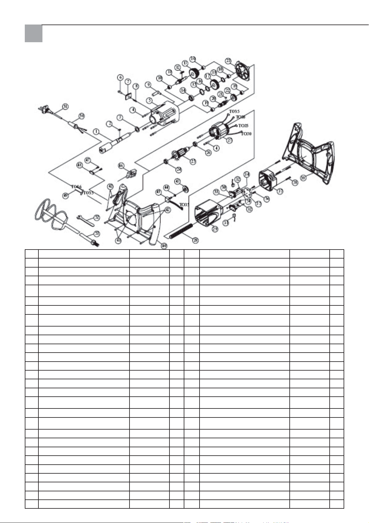
Kusovník Quick Mixx 50
č. Označenie ks č. Označenie ks
1 VRETENO M14xP2.0 1 28 OCHRANNÁ RÚRKA KÁBLA M8 1
2 PRUŽNÝ KLIN 5x5x12 1 29 TELESO MOTORA 1
3 TESNENIE 2x32x7 1 30 DRŽIAK UHLÍKOVEJ KEFY 2
4 SKRUTKA VRÁT. PRUŽNEJ
PODLOŽKY
5 PREVODOVÁ SKRIŇA 1 32 SKRUTKA M4X12 4
6 SKRUTKA S DRÁŽKOU 1 33 ŠESŤHRANNÁ MATICA M4 2
7 POSUVNÝ SPÍNAČ VOĽBY CHO-
DU
8 PRUŽINA
9 RIADIACA VIDLICA 1 36 SKRUTKA M4x25 2
10 IHLOVÉ LOŽISKO HK1010 3 37 KRYT TELESA MOTORA 1
11 HRIADEĽ S PASTORKOM 10T-130 1 38 SKRUTKA M5x20 4
12 PRUŽNÝ KLIN 5x5x45 1 39 DRŽADLO (HORE) 1
13 PREDLOHOVÉ KOLESO 30T&34T 1 40 DRŽADLO (DOLE) 1
14 LOŽISKO 6003ZZ 1 41 SKRUTKA M4x20 6
15 POISTNÝ KRÚŽOK R-35 1 42 SKRUTKA M4x25 4
16 POISTNÝ KRÚŽOK S-17 1 43 NASTAVOVACIE KOLIESKO
17 OZUBENÉ KOLESO 34T 1 44 ŠESŤHRANNÁ MATICA 1/4“x34 1
18 POISTNÝ KRÚŽOK S-15 1 45 ELEKTRONICKÝ PRESTAVOVAČ
19 IHLOVÉ LOŽISKO HK0810 2 46 PREPÍNAČ 8301 1
20 HRIADEĽ S PASTORKOM 14T&10T 1 47 SKRUTKA M4x14 2
21 PRUŽNÝ KLIN 4x4x8 1 48 KÁBLOVÁ PRÍCHYTKA 1
22 PREDLOHOVÉ KOLESO 37T 1 49 KÁBEL 16AWG 2
23 KRYT PREVODOVKY 1 50 KÁBLOVÁ VÝSTUŽ 1
24 LOŽISKO 609 2RS 1 51 SIEŤOVÝ KÁBEL 230V 1
25 KOTVA 230V 1 52 SKRUTKOVÝ KĽÚČ M22 1
26 LOŽISKO 608ZZ 1 1 53 ŠPIRÁLOVÁ MIEŠAČKA 1
27 STATOR 230V 1 54 SKRUTKA M4x10 2
M5x60 6 31 UHLÍKOVÁ KEFA 2
1 34 PRUŽINA 2
Ø6x0.6x4
1 35 SENZOR S EMV 230V 1
OTÁČOK
OTÁČOK
B100K 1
64
1
Page 65
ES-vyhlásenie o zhode
Vyhlasujeme na vlastnú zodpovednosť, že produkt
Typ: Quick Mixx 25, Quick Mixx 50
na ktorý sa vzťahuje toto vyhlásenie, sa zhoduje s nasledovnými normami a normatívnymi dokumentami:
VDE 0740 - 1 : 2003-12
DIN EN 50144-1 : 2003-11
Zodpovedajúc ustanoveniam 98/37/EHS, 73/23/EHS, 89/336/EHS.
STORCH
Malerwerkzeuge & Profigeräte GmbH
Platz der Republik 6-8
42107 Wuppertal
Jörg Heinemann – konateľ
65
Page 66

666768
Page 67

Page 68
Art.-Nr. Bezeichnung
62 97 00 Quick Mixx 25
62 98 00 Quick Mixx 50
Art.-Nr. Omschrijving
62 97 00 Quick Mixx 25
62 98 00 Quick Mixx 50
Art.-n° Désignation
62 97 00 Quick Mixx 25
62 98 00 Quick Mixx 50
N. art. Descrizione
62 97 00 Quick Mixx 25
62 98 00 Quick Mixx 50
ARt.-No. Name
62 97 00 Quick Mixx 25
62 98 00 Quick Mixx 50
čísla artiklu Označení
62 97 00 Quick Mixx 25
62 98 00 Quick Mixx 50
Výr. č. Označenie
62 97 00 Quick Mixx 25
62 98 00 Quick Mixx 50
H002524
Malerwerkzeuge & Profi geräte GmbH
Platz der Republik 6 - 8
42107 Wuppertal
Telefon: +49 (0)2 02 . 49 20 - 0
Telefax: +49 (0)2 02 . 49 20 - 111
E-mail: [email protected]
Stand: Juni 2008
Internet: www.storch.de
 Loading...