

Page 1
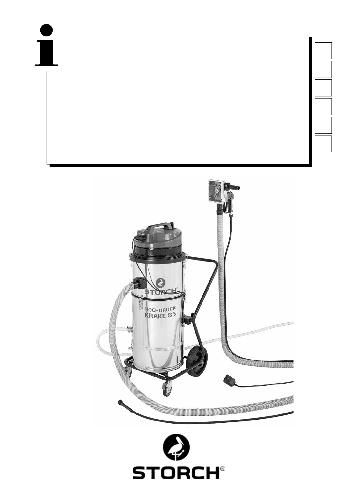
Hochdruck-Krake 85
DE
Hogedrukkrake 85
Haute pression Krake 85
Detersore ad alta pressione, tipo 85
High Pressure Water Recovery System 85
Vysokotlaké čistící zařízení Krake 85
NL
FR
IT
GB
CZ
1
Page 2

DE
Vielen Dank
für Ihr Vertrauen zu STORCH. Mit dem Kauf haben Sie sich für ein Qualitäts-Produkt entschieden.
Haben Sie trotzdem Anregungen zur Verbesserung oder aber vielleicht einmal ein Problem, so freuen wir uns sehr, von
Ihnen zu hören.
Bitte sprechen Sie mit Ihrem Außendienst-Mitarbeiter oder in dringenden Fällen auch mit uns direkt.
Mit freundlichen Grüßen
STORCH Service Abteilung
Telefon: +49 (0)2 02 . 49 20 - 112
Fax: +49 (0)2 02 . 49 20 - 244
kostenlose Service-Hotline: 08 00. 7 86 72 47
kostenlose Bestell-Hotline: 08 00. 7 86 72 44
kostenloses Bestell-Fax: 08 00. 7 86 72 43
(nur innerhalb Deutschlands)
Inhaltsverzeichnis Seite
Technische Daten 2 - 3
Lieferumfang 3
Funktionsbeschreibung 3
Prüfzeichen / Einleitbestimmungen 3
Inbetriebnahme 4
Wasserdruck / Temperatur 4
Reinigungshaube 4
Saugschlauch 5
Absauggerät mit Tauchpumpe 5
Wichtige Hinweise 5
Sicherheitshinweise 6
Wartung / Reinigung 6
Fehlerdiagnose 7
Detailzeichnungen 8 - 10
Zubehör- und Ersatzteile 11
Garantiebestimmungen 12
Konformitätserklärung 13
Technische Daten Saugaggregat:
- Spannung Wechselstrom 230 V, 50 Hz
- Stromaufnahme 1 Motor 5,5 A
- Stromaufnahme 2 Motoren 11 A
- Netzabsicherung 16 A
- Saugmotorleistung 2 x 1.220 Watt
- Luftmengenleistung max. 5.800 L/min
- Länge Saugschlauch max. 30 Meter
- Länge Anschlusskabel max. 30 m, 2,5 mm², komplett abgewickelt
- Geräteabmessung L 780 mm x B 525 mm x H 1.310 mm
- Gewicht 45 kg
- Geräuschpegel 77 db (A)
Technische Daten Tauchpumpe:
- Wechselstrom 230 V, 50Hz
- Stromaufnahme 1,4 A
- Leistungsaufnahme 320 W
- Motordrehzahl 2.800 Upm.
- Förderhöhe 1 / 3 / 5 / 7 m.
- Volumen 11 / 9 / 6 / 1 Kubikmeter / Std.
2
Page 3
Technische Daten Standard-Reinigungshaube:
- Gesamtbreite 150 mm, Gesamtlänge 340 mm, Arbeitsbreite ca. 110 mm
- Arbeitsdruck 60 - 200 bar.
- Wasserzufuhr max. 20 l / min.
- Wassertemperatur max. 85° C
Lieferumfang der STORCH-Hochdruck-Krake 85:
Standard-Reinigungshaube komplett mit Abdichtbürsten
Hochdruckschlauch 10 m
Saugschlauch 10 m
Abussschlauch 10 m
Absauggerät komplett mit Filter, Tauchpumpe und Fahrgestell
Anschlusskabel mit FI-Schutzstecker
Bedienungsanleitung
SICHERHEITSTECHNISCHE PRÜFUNGEN:
ES SIND DIE EINSCHLÄGIGEN NATIONALEN BESTIMMUNGEN EINZUHALTEN.
Allgemeine Funktionsbeschreibung:
Mit der STORCH-Hochdruck-Krake wird das von einem Hochdruckreiniger auf eine Fassade (oder andere Flächen, Wände, Decken, Fußböden) gestrahlte Wasser unmittelbar aufgefangen; die im Abwasser enthaltenen Feststoffe werden ab
einem Partikeldurchmesser von 0,21 mm ausgeltert, so dass das gereinigte Wasser in der Regel (je nach Bestimmung
der örtlichen Abwasserbehörde) umweltschonend in einen Schmutzwasserkanal geleitet werden kann. Der mitgelieferte Hochdruckschlauch wird an den Hochdruckreiniger und an die Reinigungshaube angeschlossen, über die das Wasser
über eine eingebaute Rotationsdüse auf die zu reinigende Fläche gestrahlt wird. Durch das Absauggerät wird in der
Reinigungshaube ein Vakuum erzeugt, so dass das Abwasser durch den Saugschlauch direkt in das Absauggerät abgesaugt wird, ohne dass nennenswerte Wassermengen aus der Reinigungshaube entweichen können.
Auf diese Weise kann mit dem Hochdruckreiniger sogar ohne weiteres im Innenbereich (z.B. Treppenhäusern / Kirchen)
gearbeitet werden. Das Absauggerät kann je nach gewünschter Saugleistung mit einem oder zwei Motoren eingesetzt
werden. Dazu können die Motoren an den Hauptschaltern getrennt geschaltet werden. Das Schmutzwasser wird im
Absauggerät mit einem Filter (von 210 - 400 mµ erhältlich) abgeltert und danach durch eine integrierten Tauchpumpe kontinuierlich über den Abuss-Schlauch abgepumpt.
ACHTUNG
Der Einsatz der Hochdruck-Krake 85 ist verboten, sofern Materialien mit folgenden Gefahrenhinweisen
verarbeitet wurden:
Explosiv Hoch-/Leichtentzündlich
Die Motoren der Hochdruck-Krake 85 sind nicht ex-geschützt und können entsprechend gekennzeichnete Materialien
entzünden. Bitte beachten Sie zwingend die Sicherheitsdatenblätter der Materialhersteller. Verwenden Sie niemals
Materialien mit einem Flammpunkt geringer als 21 ° C.
ACHTUNG
Der Schlauchdurchmesser des Abuss-Schlauches von ¾“ darf nicht unterschritten werden. Das Gerät wird
mit einem 400 my Mehrweglter ausgeliefert.
Prüfzeichen / Einleitbestimmungen
IP 44
3
Page 4
ACHTUNG
Vor Einleitung des Abwassers in den Schmutzwasserkanal, ist immer eine Einleitgenehmigung der zuständigen Wasserbehörde einzuholen. Verwenden Sie nur biologisch abbaubare Abbeizer der Wassergefährdungsklasse I, wenn Sie das Abwasser in einen Schmutzwasserkanal einleiten wollen, da die gelösten Abbeizmittel
nicht abgeltert werden können. Ansonsten müssen Sie je nach örtlichen Abwasserbestimmungen u. U. das
Abwasser in Tanks sammeln und entsorgen.
Der Abbeizer „Radikalfresser“ der Firma Sikkens kann mit diesem Gerät nicht verarbeitet werden.
Inbetriebnahme der STORCH-Hochdruck-Krake:
Hochdruckreiniger und Absauggerät müssen an getrennten Stromkreisen angeschlossen sein, da das Absauggerät insgesamt ca. 11 A Strom aufnimmt und je nach verwendetem Hochdruckreiniger ein einziger, mit 16 A abgesicherter Stromkreis überlastet wäre. Stellen Sie den Saugkopf mit dem oberen Behälterring auf den unteren Kessel und verbinden
diesen immer mit den 3 Spannverschlüssen! Verbinden Sie den Hochdruckreiniger mittels Hochdruckschlauch mit der
Reinigungshaube. Verbinden Sie die Reinigungshaube und das Absauggerät mit dem Saugschlauch. Stecken Sie den
Stecker der Tauchpumpe (außen am Kessel) in die vorgesehene Steckdose am Saugkopf. Prüfen Sie, ob das Absaugge-
rät inkl. Pumpe und Abussschlauch funktionsbereit ist. Schalten Sie das Absauggerät und den Hochdruckreiniger ein
(beide Motoren der Hochdruck-Krake nacheinander - nicht gleichzeitig, dann den Hochdruckreiniger) und setzen Sie die
Reinigungshaube auf die zu säubernde Fläche. Betätigen Sie den Pistolengriff an der Reinigungshaube und prüfen Sie,
ob sich die Rotationsdüse dreht.
Wasserdruck und -Temperatur:
Die Reinigungshaube darf bis max. 200 bar beaufschlagt werden. Wählen Sie für den Untergrund den geeigneten Wasserdruck am Hochdruckreiniger, damit der zu bearbeitende Untergrund nicht beschädigt wird. Für weiche Untergründe (z.
B. Putze im Innenbereich) setzten Sie die breiten Kunststoffrollen (im Lieferumfang) und die Rotationsdüse mit Flachstrahl
(Zubehör) ein. Durch den Einsatz einer Hot-Box (Art.-Nr. 65 03 00) wird das Arbeitsfortkommen durch heißes Wasser
um bis zu 40 % gesteigert und die Reinigungswirkung deutlich erhöht.
ACHTUNG
Die eingestellte Wassertemperatur darf max. 85 ° C betragen. Ein Temperaturwächter schaltet den Sauger und
die eingebaute Tauchpumpe bei Überschreiten der Temperatur aus. Nach einer Abkühlzeit von ca. 15 Minuten
lassen sich der Sauger und die Tauchpumpe wieder einschalten. Um die Abkühlphase zu unterstützen, öffnen
Sie bitte das Absauggerät, indem Sie den Saugkopf vom Kesselunterteil abnehmen.
Reinigungshaube:
ACHTUNG
Nicht in die Haube sehen oder greifen! Verletzungsgefahr! Der Haltegriff kann wahlweise rechts oder links durch
Einschrauben angebracht werden. Die Abdichtbürsten können nach Lösen der äußeren liegenden Schrauben
in der Höhe verstellt werden. Bei glatten Flächen sollten die Abdichtbürsten bis zum Anschlag eingeschoben
werden. Bei rauem Untergrund werden die Abdichtbürsten entsprechend der Vertiefungen am Untergrund weiter
ausgefahren. Stellen Sie die Abdichtbürsten so ein, dass kein Wasser aus der Haube austritt und ein leichter
und üssiger Bewegungsablauf der Reinigungshaube auf dem Untergrund möglich ist. Die Reinigungshaube
wird in vertikalen Bahnen geführt. Die Haube kann aber auch leicht seitwärts bewegt werden.
Stellen Sie sicher, dass die Reinigungshaube im Innern frei von Verschmutzungen ist, die die Drehung der Rotationsdüse
verhindern könnten. Prüfen Sie vor jedem Arbeitsbeginn den gleichmäßigen Wasseraustritt aus beiden Düsen der Rotationsdüse und ob sich dieser in der Reinigungshaube durch den Leitungswasserdruck dreht (keinesfalls mit eingeschaltetem
Hochdruckreiniger).
ACHTUNG
Sehen Sie dabei seitlich in die Reinigungshaube hinein, niemals direkt frontal auf die Rotationsdüse schauen
und dabei das Handventil betätigen! Tritt aus den Düsen nicht gleichmäßig Wasser aus, müssen diese gereinigt werden: Schrauben Sie die beiden Düsen mit einem Maulschlüssel SW 8 mm aus dem Trägerarmen
heraus und reinigen deren Innenbohrungen sorgfältig. Betätigen Sie nochmals das Handventil um eventuelle
Schmutzpartikel aus den Trägerrahmen heraus zu spülen. Anschließend die Düsen wieder einschrauben und
mit dem Maulschlüssel fest anziehen.
4
Page 5
Entfernen Sie Schmutzpartikel, die sich in den Lagern der Gleitrollen festgesetzt haben könnten, wenn die Gleitrollen
sich nicht mehr leicht drehen lassen.
Hinweis:
Regelmäßige Reinigung, Pege und Wartung nach Arbeitsende vermeiden Störungen!
Saugschlauch:
Die max. Saugschlauchlänge darf 30 m nicht überschreiten. Keine höheren Schlauchlängen als notwendig verwenden. Ach-
ten Sie darauf, dass der Saugschlauch immer in geraden Bahnen verlegt ist und nicht „durchhängt“ und / oder abknickt.
Bei Arbeitsende den Schlauch ausreichend durchspülen, damit dieser nicht verstopft. Bei Arbeiten auf dem Gerüst empfehlen wir zur Zugentlastung den Saugschlauch am Gerüst mit Schlauchhaltern (Art.-Nr. 64 24 25) abzuhängen.
Absauggerät mit Tauchpumpe:
Der Saugkopf ist mit einer Saugstromunterbrechung ausgestattet, die die Saugleistung unterbricht, wenn der Feststoffanteil im Filterkorb zu hoch ist, das Wasser aus dem Filterkorb nicht mehr ablaufen kann und der Wasserstand im Filterkorb
die max. Höhe erreicht hat.
ACHTUNG
Die Arbeiten sind dann sofort zu unterbrechen, Gerät abschalten und der Filterkorb ist zu reinigen.
Zum Entleeren des Filters die 3 Spannverschlüsse am Kessel lösen und den Kesselaufsatz neben den Kessel
stellen. Nun können Sie den Stützkorb bequem herausziehen. Den Mehrweglter reinigen, auswaschen und
das Gerät in umgekehrter Reihenfolge wieder zusammenbauen. Beim Wiedereinsetzen des Stützkorbes bitte darauf achten, dass der Dichtring sauber ist und glatt abdichtet! Füllt sich der Filterkorb schon nach kurzer Zeit wird
empfohlen bei Reinigungsarbeiten den Untergrund abzubürsten und bei Abbeizarbeiten die angelöste Beschichtung mit
einem breiten Spachtel abzunehmen und / oder einen gröberen Mehrweglter in den Filterkorb einzusetzten. Neben dem
Serien-Mehrweglterlter mit 400 mµ bieten wir auch Mehrweglter in gröberen Maschenweiten an.
Um Restwasser aus dem Kessel zu entleeren, kann dieser gekippt werden. Arretieren Sie vorher die vorderen Laufrollen
am Fahrgestell, damit ein unbeabsichtigtes Wegrollen des Fahrgestells vermieden wird.
Die Tauchpumpe schaltet sich über einen Schwimmerschalter automatisch ein und aus.
Eine Füllstandskontrolle entfällt und Arbeitsunterbrechungen durch Entleeren des Behälters werden vermieden. Die Pumpe
muss jedoch über die Steckdose am Saugkopf mit Strom versorgt werden. Bei Erstgebrauch oder nach längerer Standzeit
(Wochen/Monate), kann sich in der Tauchpumpe ein Luftpolster bilden, so dass kein Wasser in die Pumpenkammer ießt.
In dem Fall stellen Sie sicher, dass die Pumpe komplett im Wasser steht. Stecken Sie den Netzstecker der STORCH
Hochdruck-Krake in eine geerdete Steckdose und verbinden den Stecker der Pumpe mit dem Saugkopf. Die Pumpe läuft
an. Nun drücken Sie von Hand Schwimmer nach unten (Pumpe schaltet sich aus), halten diesen für kurze Zeit unten und
lassen diesen wieder los (Pumpe schaltet sich wieder ein). Wiederholen Sie diesen Vorgang bis das Wasser abgepumpt
wird.
ACHTUNG
Wichtige Hinweise:
- Die STORCH Hochdruck-Krake darf nur zum Nasssaugen und nicht zum Saugen von trockenem,
staubigem Gut verwendet werden.
- Die maximale Wassertemperatur darf 85°C nicht übersteigen.
- Vor Arbeitsbeginn prüfen Sie bitte unbedingt, ob der Stecker der Tauchpumpe in den Saugkopf
eingesteckt ist.
- Die Spannverschlüsse am Behälter müssen fest verschlossen sein.
- Verstopfungen des Saugschlauches sind sofort zu beheben. Diese erkennt man durch hörbar steigende
Drehzahlen der Motoren und abnehmende Saugleistung. Das Gerät muss unverzüglich ausgeschaltet
werden. Bei Arbeitsende muss der Saugschlauch vollständig entleert und durchgespült werden.
- Regelmäßige Kontrolle des Luftlters auf Verschleiß, Verschmutzung und Beschädigungen.
Ein nicht intakter Filter beeinträchtigt die Leistung und Sicherheit des Gerätes.
- Regelmäßige Kontrolle der Saugstromunterbrechung auf Sauberkeit und Freigängigkeit sowie auf
Beschädigungen der Kugel und Dichtung (Sitz der Kugel).
- Austausch verschlissener und nicht intakter Teile.
Bei Beachtung dieser wichtigen Hinweise werden Sie immer ein zuverlässiges Arbeitsgerät zur Hand haben. Bei Missachtung dieser Punkte erlischt bei dadurch entstandenen Schäden der Garantieanspruch.
5
Page 6
Sicherheitshinweise:
Bei Arbeiten mit den Reinigungshauben dürfen die Hände oder andere Körperteile nicht vor die unter Druck
stehenden Düsen oder in den Wasserstrahl gebracht werden. Der Handhebel des HD–Absperrventils an der
Reinigungshaube darf in der Einschaltstellung nicht arretiert werden. Bei Arbeitsunterbrechung und Arbeits-
ende muss der Handhebel des HD–Absperrventils gegen unbeabsichtigtes Betätigen gesichert werden (Si-
cherheitsriegel ausklappen). Die Reinigungshaube nicht auf Personen richten, auch durch den Restdruck nach
Abschalten des Hochdruckreinigers besteht Verletzungsgefahr durch den Wasserdruck. Nicht in die unmittelbare Nähe
des Hochdruckstrahles greifen, Abstand mind. 30 cm. Wird das Gerät nicht benötigt (Arbeitspausen), schalten Sie die
Hochdruck-Krake und den Hochdruckreiniger aus und entlasten den Druck an der Reinigungshaube durch Abziehen des
Handventils.
ACHTUNG
Die Rotationsdüse im Innern der Reinigungshaube nur reinigen bzw. entfernen, wenn der Hochdruckschlauch
von der Reinigungshaube abmontiert ist. Verletzungsgefahr!
ACHTUNG Wärme:
Bei Arbeiten mit heißem Wasser tragen Sie generell geeignete Schutzausrüstung (z. B. Handschuhe, Schutzbrille, Kopfbedeckung bei Überkopfarbeiten). Nicht unmittelbar nach Beendigung der Arbeiten das Gerät reinigen.
Lassen Sie den Sauger bei abgenommenem Saugkopf noch ca. 15 Minuten abkühlen. Achten Sie bei Arbeiten
mit Heißwasser auf Gerüsten, dass sich auf den unteren Gerüstlagen keine anderen Personen benden, um
auch hier die Verbrühungsgefahr auszuschließen.
ACHTUNG
Das Gerät darf nicht:
- an explosionsgefährdeten Orten eingesetzt werden bzw. explosionsgefährdete Stoffe absaugen. Dies gilt
insbesondere für Bereiche, in denen nur Maschinen eingesetzt werden dürfen die nach B1 geprüft sind.
- zur Aufnahme gesundheitsgefährdender Stäube verwendet werden.
- brennbare Flüssigkeiten und Säuren aufsaugen.
- ölhaltige oder nicht leitende Flüssigkeiten absaugen.
- Zündquellen aufsaugen.
- Ohne Filter zum Staubsaugen verwendet werden.
ACHTUNG Elektro:
Die Netzanschlussleitung darf nicht überfahren, gequetscht oder gezerrt werden. Die Netzanschlussleitung
von Tauchpumpe und Saugaggregat muss regelmäßig auf evtl. Schäden überprüft werden. Wenn diese schad-
haft ist, darf die Maschine nicht benutzt werden. Bei Ersatz von Netz- oder Geräteanschlussleitungen darf
die vom Hersteller angegebene Ausführung nicht verändert werden. Die Kupplungen der evtl. verwendeten
Verlängerungskabel müssen spritzwassergeschützt sein. Achten Sie darauf, dass Sie bei der Innenreinigung
des Kessels die Pumpenleitung nicht beschädigen. Vor jeglichen Wartungsarbeiten muss unbedingt der Netz-
stecker gezogen werden. Beim Reinigen und Warten von Maschinen, beim Auswechseln von Teilen oder beim Umstellen
in eine andere Arbeitsfunktion muss der Hauptschalter auf “0” gestellt und der Netzstecker gezogen werden. Die Maschine darf nur von Personen bedient werden, die eingewiesen, insbesondere über Gefahrenhinweise unterrichtet und
ausdrücklich mit der Benutzung beauftragt wurden. Beachten Sie die am Einsatzort der Maschine gültigen Sicherheitsund Unfallverhütungsvorschriften.
Das Gerät besitzt einen Spannungsbereich, von dem eine elektrische Gefahr für Mensch und Tier ausgehen kann. Es
darf nur von autorisierten Personen aufgeschraubt und / oder demontiert werden. Ebenso dürfen Instandhaltung und
Reparaturen nur von Elektrofachkräften und autorisierten Fachwerkstätten ausgeführt werden. Der Betrieb des Gerätes
geschieht auf eigene Verantwortung und Gefahr des Käufers / Nutzers.
Wartung / Reinigung:
Nach Gebrauch den Rest des Schmutzwassers aus dem Kessel des Absauggerätes auskippen. Den Kessel immer mit
sauberem Wasser ausspülen. Steine, Farbreste und Schmutz von der Saugöffnung der Tauchpumpe entfernen. Den Kessel
nach der Reinigung nicht mit dem Saugkopf verschließen, denn beide Teile müssen trocknen.
Bei der Reinigung kontrollieren Sie auch die Geräteluftlterpatrone unter dem Saugkopf auf Verunreinigung und Beschädigungen. Um eine optimale Saugstromunterbrechung bei vollen Filterkorb zu gewährleisten, ist die im Luftlterkorb
bendliche Abdichtkugel in Verbindung mit Filterkorb und Dichtung sauber zu halten.
Die Reinigungshaube nach jedem Gebrauch gründlich mit klarem Wasser ausspülen. Achten Sie auch auf ausreichende
Reinigung der Abdichtbürsten. Gelegentlich sollten die Laufrollen ausgebaut werden, um Schmutz aus der Rollenlagerung
zu entfernen. Lösen Sie hierzu die seitlichen Schrauben (vorher die Abdichtbürsten entfernen).
6
Page 7

Fehlerdiagnose:
• Reinigungswirkung mit der Reinigungshaube ist nicht ausreichend:
• Die Rotationsdüse dreht sich nicht
• Kalkablagerung am Rotationskörper
• Durch Schmutzpartikel blockiert
• Von Hand mehrfach durchdrehen (HDR erst Drucklos machen)
• Auseinanderschrauben und säubern
• Bei sehr hohem, plötzlich auftretendem Wasserdruck kann die Dreckfräse stehenbleiben. In diesem Fall den HDAbsperrgriff mehrmals betätigen.
• Leistet der Hochdruckreiniger ausreichend Druck?
• Ist die Wasserzufuhr zum Hochdruckreiniger ausreichend? (Zuleitung immer ¾“)
• Evtl. Rotationsdüse verschlissen und muss ausgewechselt werden
• Es wird kein Wasser aus dem Absauggerät abgepumpt:
• Luftpolster in der Pumpe
• Stromzuführung zur Tauchpumpe am Saugkopf eingesteckt?
• Tauchpumpe steht im Schlamm und kann kein Wasser absaugen
• Abussschlauch abgeknickt.
• Keine oder zu geringe Saugleistung:
• Saugstromunterbrechung da Feststoffanteil im Filterkorb zu hoch
• Abschaltung des Gerätes durch Thermoschalter (hervorgerufen durch Saugstromunterbrechung / verstopfter, abgeknickter oder durchhängender Saugschlauch / zu hohe Wassertemperatur)
• Kesselaufsatz mit Motor exakt auf dem Kesselunterteil?
• Dichtring am Filterkorb zwischen den Kesseln auf Beschädigung und Verschmutzung prüfen
• Verbindung Saugschläuche prüfen
• Nur ein Saugmotor eingeschaltet
• Laufrollen an der Reinigunshaube drehen sich nicht:
• Schmutz zwischen Lager und Laufrolle entfernen.
• Wasseraustritt aus der Haube:
• Verklebte Abdichtbürsten reinigen bzw. austauschen.
• Saugleistung zu gering
• Falsche Höheneinstellung der Abdichtbürsten
• Saugstromunterbrechung ist aktiv (Filterkorb reinigen)
• Abzug der Reinigungshaube lässt sich nicht abziehen:
• Arretierung lösen
• Sauger schaltet ab:
• Abschaltung des Gerätes durch Thermoschalter (hervorgerufen durch Saugstromunterbrechung
• Verstopfter, abgeknickter durchhängender Saugschlauch oder zu hohe Wassertemperatur)
• Stromzufuhr überprüfen: Evtl. ist der FI-Schutzstecker aktiv. Ausschließlich 2,5mm² starkes
• Verlängerungskabel benutzen. Die Länge darf 30 Meter nicht überschreiten. Kabeltrommeln komplett abwickeln.
• Falten-Luftlter unter Sauger nass und / oder verschmutzt
• Prüfen ob Pumpenstecker in Sauger eingesteckt (sonst steigt der Wasserstand und die Saugstromunterbrechung
schaltet).
• Motoren einzeln Einschalten.
• Alle Geräte an verschiedenen Stromkreisen anschließen.
• Stromversorgung 230V prüfen.
• Schalten Sie beide Hauptschalter in Stellung „0“, beseitigen Sie den Grund der Störung und schalten nach einer
Wartezeit von ca. 5 min das Gerät wieder ein.
7
Page 8
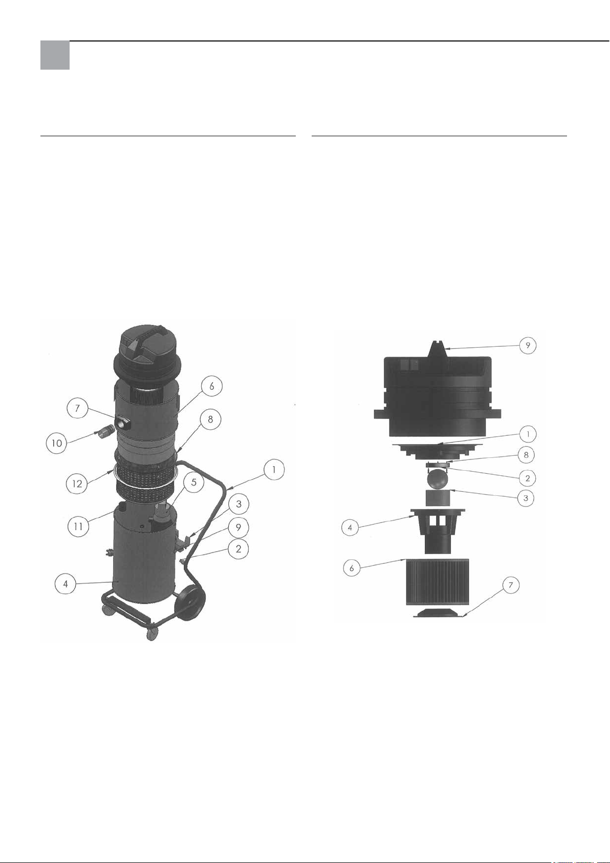
Hochdruck-Krake 85 komplett:
Saugkopf:
Pos. Bezeichnung Art.-Nr.
1 Fahrgestell komplett 65 80 11
2 Distanzstück für Sauger 65 80 16
3 Kippvorrichtung 65 77 47
4 Kessel unten komplett (ohne Pumpe) 65 80 08
5 Tauchpumpe 65 77 17
6 Kesselaufsatz komplett 65 80 09
7 Kesselkupplung komplett
inklusive Einströmstutzen 65 80 13
8 Filterstützkorb 65 80 12
9 Kabelverschraubung komplett Krake 85 65 80 17
10 Schlauchmuffe 65 80 18
11 Muffe mit Rückschlagklappe 65 80 14
12 Dichtung für Stützkorb 65 77 20
Pos. Bezeichnung Art.-Nr.
1 Motoraufnahmeplatte 65 80 66
2 Dichtung Abschaltkugel 65 80 19
3 Filtersieb 65 80 73
4 Schwimmergehäuse 65 80 72
5 Abschaltkugel 65 80 21
6 Faltenlter C 65 77 25
7 Halter für Filterpatrone 65 80 75
8 Spanplattenschraube 3 x 20 65 80 22
9 Saugkopf 2.400W blau komplett 65 80 20
8
Page 9
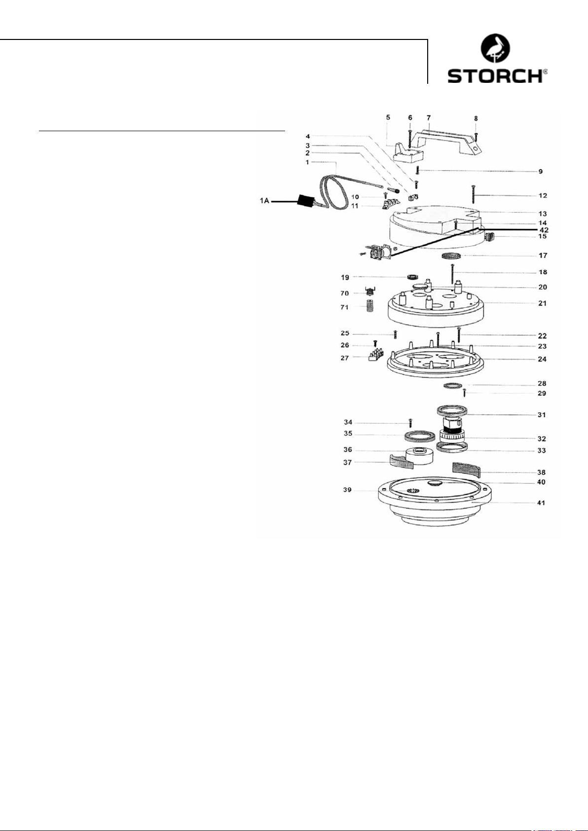
Saugkopf:
Pos. Bezeichnung Art.-Nr.
1 Stromkabel 2 x 1,5, mit Stecker 65 80 31
1a Personenschutz-Stecker IP 44 60 02 46
2 Kabelführung für Saugkopf 65 80 33
3 Kabelklemme für Saugkopf 65 80 34
4 Kreuzschraube M 5 x 20 65 80 35
5 Kabelhalter für Saugkopf HDK 85 65 80 36
6 Schraube 5,2 x 50 65 80 37
7 Handgriff für Saugkopf HDK 85 65 80 38
8 Kreuzschraube M 5 x 35 65 80 39
9 Kreuzschraube M 5 x 20 65 80 35
10 Kreuzschraube M 5 x 14, 65 80 41
11 Anschlussklemme 65 80 42
12 Schraube 5,2 x 50 65 80 37
13 Gehäusedeckel für Saugkopf 65 80 43
14 Kreuzschraube M 5 x 20 65 80 35
15 Schalter Ein / Aus für Saugkopf 65 80 44
17 Filter für Saugkopf HDK 85 65 80 45
18 Schraube 5,2 x 50 65 80 37
19 Kabelschutzring 65 80 47
20 Blindstopfen 65 80 48
21 Motorabdeckung für Saugkopf 65 80 49
22 Blechschraube 3 x 40 65 80 51
23 Blechschraube 3 x 40 65 80 51
24 Aufnahmering für Saugkopf 65 80 52
25 Kreuzschraube M 5 x 30 65 80 53
26 Blechschraube 4,3 x 19 65 80 54
27 Anschlussklemme 4-polig 65 80 55
28 Dichtring 65 80 56
29 Kreuzschraube M 5 x 20 65 80 35
31 Motordichtung für Saugkopf 65 80 57
32 Motor für HDK 85 65 80 03
33 Motordichtung für Saugkopf 65 80 57
34 Kreuzschraube M 5 x 20 65 80 35
35 Motordichtung für Saugkopf 65 80 57
36 Abstandhalter 65 80 61
37 Dichtungsstück für Saugkopf 65 80 62
38 Filter 65 x 10, L = 120 65 80 63
39 Kupplungsscheibe 65 80 64
40 Abdeckkappe 65 80 65
41 Motoraufnahmeplatte 65 80 66
42 Schukosteckdose für Saugkopf 65 80 67
70 Thermoschalter für HDK 85 65 80 07
71 Halter für Thermokontakt 65 80 68
9
Page 10

Standard-Reinigungshaube Ersatzteile:
Pos. Bezeichnung Art.-Nr.
1 Haube 65 74 01
3 HD-Absperrventil (neu) 65 71 30
4 Dichtbürstensatz, 4-teilig 65 74 18
6 Rolle 65 74 04
7 Lagerbuchse 65 74 05
8 Lagerzapfen 65 74 06
9 Anschlußnippel 65 71 21
10 Winkel 90 Grad 65 71 23
12 Wechselteil Punktstrahl 65 75 51
12a Wechselteil Flachstrahl 65 75 52
15 Düse 0,95 65 74 08
16 Düse 1,27 (mit Rille) 65 74 19
17 Linsenschraube M 4 x 8 65 74 12
18 Linsenschraube M 5 x 10 65 74 13
ohne Abbildung:
Teonrollen breit 65 75 54
Thermometer mit Klebering 65 75 53
* Verschleißteile
ACHTUNG
Wir empfehlen den Einsatz der beigefügten Düsen mit 1,27 mm Durchmesser,
falls der eingesetzte Hochdruckreiniger mehr als 11 l Wasser pro Minute fördert.
10
Page 11

Zubehör und Ersatzteile:
Bezeichnung Art.-Nr.
Pro-Hochdruckreiniger 135 bar 65 60 00
Pro-Hochdruckreiniger 220 bar, Benzin 65 60 50
Verlängerungs-Saugschlauch kpl., 10 m 65 70 10
Verlängerungs-HD-Schlauch, 10 m, Druck- 65 65 14
belastung bis 400 bar, max. Temperaturbelastung 150° C
Verlängerungs-HD-Schlauch, 10 m, inkl. 65 65 30
Verbindungsdoppelnippel, Druckbelastung
bis 210 bar, max. Temperaturbelastung 150° C
Doppelnippel Verbindungen 65 65 31
Huchdruckschlauch M 22 x 1,5
Verlängerungs-Abussschlauch 10 m 65 70 16
Schlauchhalter 64 24 25
Kleinächen-Reinigungshaube 6 x 6 cm 65 76 50
Großächen-Reinigungshaube 44 x 40 cm 65 75 60
Bodenreinigungsvorrichtung für 65 75 80
Großächen-Reinigungshaube
Wasseransaugdüse zum Aufsaugen von Wasser 65 10 30
Saugrohr Metall 1,2 m 65 10 10
Bezeichnung Art.-Nr.
Absauggerät Ersatzteile:
Mehrweg-Gewebeltersack 210 mµ 65 77 30
Mehrweg-Gewebeltersack 300 mµ 65 77 31
Mehrweg-Gewebeltersack 400 mµ 65 77 32
Kupplung für Saugschlauch 65 70 11
11
Page 12

Garantie
Garantiebedingungen
Für unsere Geräte gelten die gesetzlichen Gewährleistungsfristen von 12 Monaten ab Kaufdatum / Rechnungsdatum des
gewerblichen Endkunden. Sind längere Fristen im Wege einer Garantieerklärung von uns ausgelobt, sind diese extra in
den Bedienungsanleitungen der betroffenen Geräte ausgewiesen.
Geltendmachung
Bei Vorliegen eines Gewährleistungs- bzw. Garantiefalles bitten wir, dass das komplette Gerät zusammen mit der
Rechnung frei an unser Logistik Center in Berka oder an eine von uns autorisierte Service- Station eingeschickt wird.
Zuvor bitten wir Sie, uns unter unserer kostenlosen STORCH Service-Hotline 08 00. 7 86 72 47 zu kontaktieren.
Gewährleistungs- bzw. Garantieanspruch
Reparaturansprüche bestehen ausschließlich an Werkstoff- oder Fertigungsfehler sowie ausschließlich bei bestimmungs-
gemäßer Verwendung des Geräts. Verschleißteile wie Abdichtbürsten, Laufrollen, Luftlter, Dichtungen, Rotationsdüse,
Mehrweglter usw. fallen nicht unter derartige Ansprüche. Sämtliche Ansprüche erlöschen durch den Einbau von Teilen
fremder Herkunft, bei unsachgemäßer Handhabung und Lagerung sowie bei offensichtlicher Nichtbeachtung der Betriebsanleitung.
Durchführung von Reparaturen
Sämtliche Reparaturen dürfen ausschließlich durch unser Werk oder von STORCH autorisierten Service-Stationen
durchgeführt werden.
12
Page 13
EG-Konformitätserklärung
Name / Anschrift des Ausstellers: STORCH Malerwerkzeuge & Profigeräte GmbH
Platz der Republik 6-8
D - 42107 Wuppertal
Hiermit erklären wir,
dass das nachstehend genannte Gerät aufgrund dessen Konzipierung und Bauart sowie in der von uns in
Verkehr gebrachten Ausführung den einschlägigen, grundlegenden Sicherheits- und Gesundheitsanforderungen der EG-Richtlinien entspricht.
Bei einer nicht mit uns abgestimmten Änderung des Gerätes verliert diese Erklärung ihre Gültigkeit.
Bezeichnung des Gerätes: Hochdruck-Krake 85
Geräte-Typ: Nass-Sauger
Artikel-Nummer: 65 80 00
Angewandte Richtlinien
Maschinen-Richtlinie: 2006 / 42 / EG
Niederspannungs-Richtlinie: 2006 / 95 / EG
EG-Richtlinie Elektromagnetische
Verträglichkeit: 2004 / 108 / EG
Bevollmächtigter für die Zusammenstellung der technischen Unterlagen:
STORCH Malerwerkzeuge & Profigeräte GmbH
Platz der Republik 6-8
42107 Wuppertal
Jörg Heinemann
- Geschäftsführer -
Wuppertal, 02 - 2013
13
Page 14

NL
Hartelijk dank
voor uw vertrouwen in STORCH. Met deze aankoop hebt u voor een kwaliteitsproduct gekozen.
Als u desondanks een tip voor verbeteringen hebt of wellicht ooit een probleem ondervindt, dan horen wij graag van u.
Neem contact op met de medewerker buitendienst of in dringende gevallen rechtstreeks met ons.
Met vriendelijke groeten,
STORCH serviceafdeling
Tel.: +49 (0)2 02 . 49 20 - 112
Fax: +49 (0)2 02 . 49 20 - 244
Gratis service-hotline: 08 00. 7 86 72 47
Gratis bestel-hotline: 08 00. 7 86 72 44
Gratis bestel-fax: 08 00. 7 86 72 43
(alleen binnen Duitsland)
Inhoudsopgave Pagina
Technische gegevens 14 - 15
Leveringsomvang 15
Functiebeschrijving 15
Keurmerken / vergunningen 15
Inbedrijfstelling 16
Waterdruk / temperatuur 16
Reinigingskap 16
Zuigslang 17
Afzuigapparaat met dompelpomp 17
Belangrijke richtlijnen 17
Veiligheidsrichtlijnen 18
Onderhoud / reiniging 18
Foutdiagnose 19
Detailtekeningen 20 - 23
Toebehoren en vervangende onderdelen 23
Garantiebepalingen 24
Conformiteitverklaring 25
Technische gegevens zuigaggregaat:
− Spanning wisselstroom 230 V, 50 Hz
− Stroomverbruik 1 motor 5,5 A
− Stroomverbruik 2 motoren 11 A
− Afzekering 16 A
− Vermogen zuigmotor 2 x 1.220 Watt
− Luchtcapaciteit max. 5.800 L/min
− Lengte zuigslang max. 30 meter
− Lengte aansluitkabel max. 30 m, 2,5 mm², compleet afgewikkeld
− Afmetingen apparaat L 780 mm x B 525 mm x H 1.310 mm
− Gewicht 45 kg
− Geluidsniveau 77 db (A)
Technische gegevens dompelpomp:
− Wisselstroom 230 V, 50 Hz
− Stroomverbruik 1,4 A
− Wattage 320 W
− Motortoerental 2.800 rpm.
− Transporthoogte 1 / 3 / 5 / 7 m.
− Volume 11 / 9 / 6 / 1 kubieke meter/uur
14
Page 15
Technische gegevens Standaard reinigingskap:
− Totale breedte 150 mm, totale lengte 340 mm, werkbreedte ca. 110 mm
− Werkdruk 60-200 bar.
− Watertoevoer max. 20 l/min.
− Watertemperatuur max. 85° C
Leveringsomvang van de STORCH-hogedrukkrake 85:
Standaard reinigingskap compleet met afdichtingsborstels
Hogedrukslang 10 m
Zuigslang 10 m
Afvoerslang 10 m
Afzuigapparaat compleet met lter, dompelpomp en onderstel
Aansluitkabel met FI-veiligheidsstekker
gebruiksaanwijzing
VEILIGHEIDSTECHNISCHE CONTROLES:
DE GELDENDE NATIONALE BEPALINGEN DIENEN IN ACHT TE WORDEN GENOMEN.
Algemene functiebeschrijving:
Met de STORCH-hogedrukkrake wordt het water dat door een hogedrukreiniger op een gevel (of andere oppervlakken, muren, plafonds, vloeren) wordt gespoten direct opgevangen; de vaste stoffen in het afvalwater worden vanaf
een deeltjesdiameter van 0,21 mm gelterd, zodat het gereinigde water in de regel (afhankelijk van de bepalingen van
de plaatselijke waterautoriteiten) op milieuvriendelijke wijze in het afvalwaterriool kan worden afgevoerd. De meege-
leverde hogedrukslang wordt op de hogedrukreiniger en op de reinigingskap aangesloten, waarmee het water via een
ingebouwde rotatiesproeikop op het te reinigen oppervlakte wordt gespoten. Door middel van het afzuigapparaat wordt
er in de reinigingskap een vacuüm gecreëerd, zodat het afvalwater via de zuigslang rechtstreeks in het afzuigapparaat
wordt gezogen zonder dat hierbij noemenswaardige waterhoeveelheden uit de reinigingskap kunnen ontsnappen.
Op deze manier kan met de hogedrukreiniger zonder meer binnenshuis (bijv. trappenhuizen / kerken) worden gewerkt.
Het afzuigapparaat kan afhankelijk van het gewenste zuigvermogen met één of twee motoren worden ingezet. Hiertoe
kunnen de motoren via de hoofdschakelaars gescheiden worden geschakeld. Het afvalwater wordt in het afzuigappa-
raat met een lter (van 210 - 400 mµ verkrijgbaar) gelterd en vervolgens door een ingebouwde dompelpomp via de
afvoerslang afgepompt.
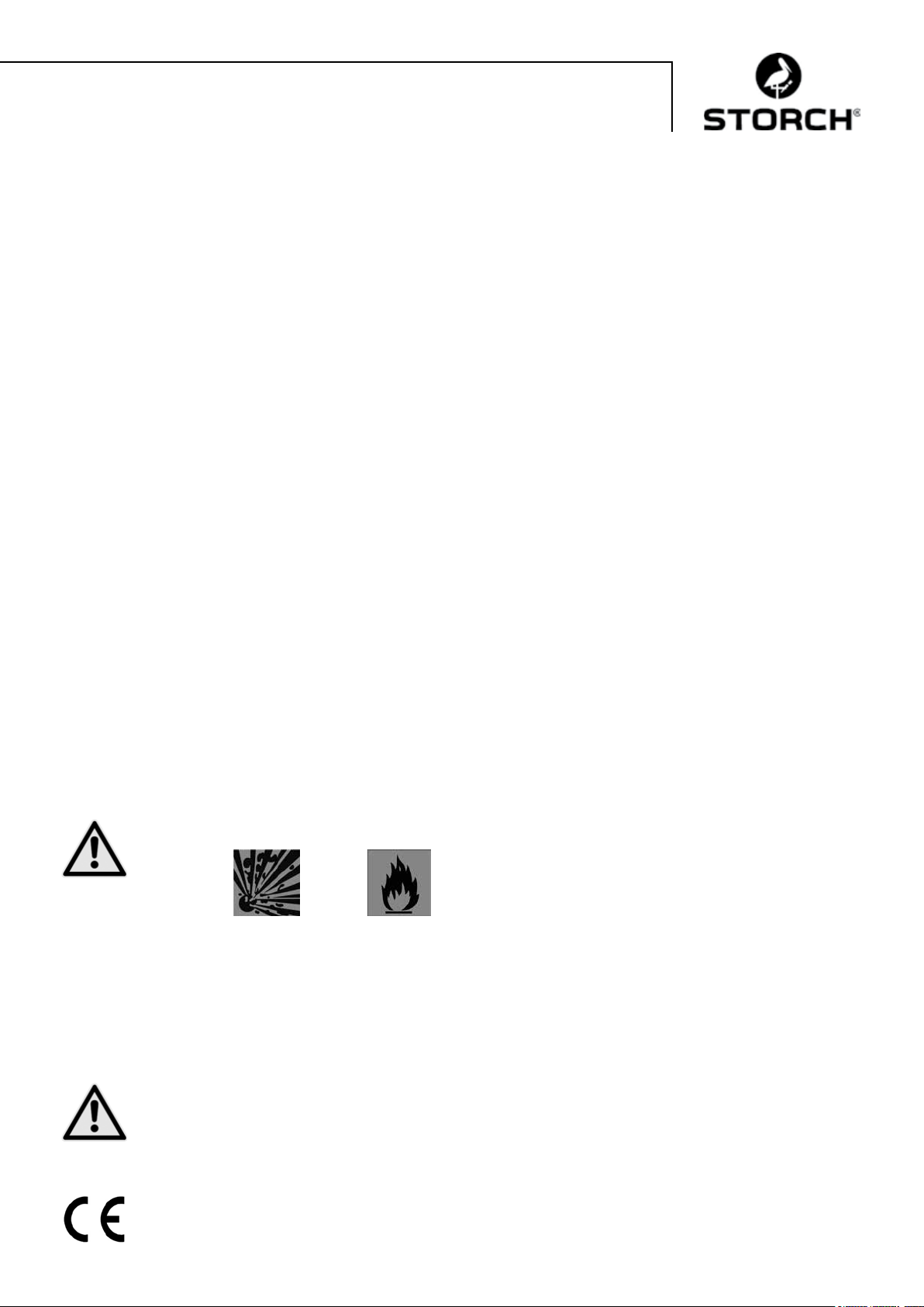
OPGELET
Het gebruik van de hogedrukkrake 85 is verboden wanneer er materialen met de volgende waarschuwingen
worden verwerkt:
Explosief Sterk / licht ontvlambaar
De motoren van de hogedrukkrake 85 zijn niet explosiebeveiligd en kunnen als zodanig aangeduide materialen tot ontvlamming brengen. Raadpleeg altijd de veiligheidsgegevens van de materiaalfabrikant. Gebruik nooit materialen met
een vlampunt lager dan 21° C.
OPGELET
De diameter van de afvoerslang van ¾“ mag niet worden overschreden. Het apparaat wordt geleverd met
een 400 my meerwegfilter.
Certificaat / lozingsbepalingen
IP44
15
Page 16
OPGELET
Voor afvoer van het afvalwater in het afvoerkanaal (riool) dient er altijd een vergunning van de bevoegde
instantie aanwezig te zijn. Gebruik alleen biologisch afbreekbaar afbijtmiddel van watergevaarklasse I
wanneer u het afvalwater in een afvoerkanaal (riool) wilt lozen omdat het opgeloste afbijtmiddel niet kan
worden gefilterd. Anders moet u afhankelijk van de plaatselijke bepalingen het afvalwater in tanks verzame-
len en afvoeren.
Het afbijtmiddel "Radikalfresser" van Sikkens kan niet worden gebruikt met dit apparaat.
Ingebruikname van de STORCH-hogedrukkrake:
Hogedrukreiniger en afzuigapparaat moeten op gescheiden stroomkringen aangesloten zijn, aangezien het afzuigapparaat in totaal ca. 11 A stroom opneemt en afhankelijk van de gebruikte hogedrukreiniger een enkele, met 16 A bevei-
ligde stroomkring overbelast zou raken. Zet de zuigkop met de bovenste ring op de onderste ketel en zet deze altijd
vast met de 3 spansluitingen! Sluit de hogedrukreiniger met de hogedrukslang aan op de reinigingskap. Verbind de
reinigingskap en het afzuigapparaat met de zuigslang. Steek de stekker van de dompelpomp (buiten op de ketel) in
het stopcontact op de zuigkop. Controleer of het afzuigapparaat inclusief pomp en afvoerslang gereed voor gebruik zijn.
Schakel het afzuigapparaat en de hogedrukreiniger in (beide motoren van de hogedrukkrake na elkaar - niet tegelijkertijd, vervolgens de hogedrukreiniger) en plaats de reinigingskap op het te reinigen oppervlak. Gebruik de pistoolgreep
op de reinigingskap en controleer of de rotatiesproeikop draait.
Waterdruk en temperatuur:
De reinigingskap mag tot max. 200 bar worden belast. Kies de voor de ondergrond geschikte waterdruk op de hogedru-
kreiniger, zodat de ondergrond niet beschadigd wordt. Voor zachte ondergronden (bijvoorbeeld pleisterwerk binnenshuis)
gebruikt u de brede kunststofrollen (meegeleverd) en de rotatiesproeikop met platte straal (toebehoren). Door gebruik
van een Hot-Box (art.-nr. 65 03 00) neemt het resultaat door heet water tot 40 % toe en wordt de reinigingswerking
duidelijk verhoogd.
OPGELET
De ingestelde watertemperatuur mag max. 85 ° C bedragen. Een temperatuurbewaker schakelt de zuiger en
de ingebouwde dompelpomp bij overschreiden van de temperatuur uit. Na een afkoeltijd van ca. 15 minuten
kunnen de zuiger en de dompelpomp weer worden ingeschakeld. Ter ondersteuning van de afkoelfase opent
u het afzuigapparaat door de zuigkop van de ketelonderstuk te nemen.
Reinigingskap
OPGELET
Niet in de kap kijken of grijpen! Kans op verwondingen! De handgreep kan desgewenst rechts of links erin
geschroefd worden. De afdichtingsborstels kunnen na het losdraaien van de buitenliggende schroeven gem-
akkelijk in de hoogte worden ingesteld. Bij gladde vlakken moeten de afdichtingsborstels tot aan de aanslag worden geschoven. Bij een ruwe ondergrond de borstels dienovereenkomstig langer instellen. Stel de
afdichtingsborstels zodanig in, dat er geen water aan de zijkant naar buiten komt en een gemakkelijke en
vloeiende beweging van de reinigingskap mogelijk is. Werk in verticale banen met de reinigingskap. De kap
kan echter ook een beetje zijwaarts worden bewogen.
Controleer of de reinigingskap van binnen schoon is en geen vuil bevat dat de draaiing van de rotatiesproeikop kan belem-
meren. Controleer voor aanvang van het werk altijd of het water gelijkmatig uit de beide sproeiers van de rotatiesproeikop
komt en of de kop door de leidingwaterdruk draait in de reinigingskap (controleer dit nooit terwijl de hogedrukreiniger is
ingeschakeld).
OPGELET
Kijk hierbij van de zijkant in de reinigingskap, nooit direct van voren naar de rotatiesproeikop kijken en hierbij
de handklep gebruiken! Als het water niet gelijkmatig uit de sproeikop komt, dan moet deze worden gerei-
nigd: schroef de beiden sproeikoppen met een steekslleutel SW 8 mm uit de dragerarmen en reinig de bin-
nenboringen zorgvuldig. Gebruik hierbij nogmaals handklep om eventuele vuilresten uit het dragerframe te
spoelen. Vervolgens de sproeikoppen weer vastschroeven en met de steeksleutel stevig aandraaien.
16
Page 17
Verwijder het vuil dat zich in de lagers van de geleidingswieltjes heeft vastgezet wanneer de geleidingswieltjes niet meer
gemakkelijk gedraaid kunnen worden.
Tip:
Regelmatige reiniging en onderhoud na het werk voorkomt storingen!
Zuigslang:
De maximale lengte van de zuigslang is 30 m. Gebruik geen langere slangen dan nodig. Zorg ervoor dat de zuigslang
altijd in rechte banen ligt en niet doorhangt en / of knikt.
Na de werkzaamheden de slang goed doorspoelen zodat deze niet verstopt raakt. Bij werkzaamheden op een steiger raden
wij aan de zuigslang met de slanghouders (Art.-Nr. 64 24 25) aan de steiger te hangen.
Afzuigapparaat met dompelpomp:
De zuigkop is uitgerust met een zuigstroomonderbreking die de zuigwerking onderbreekt zodra het aandeel vaste deeltjes
in de lter te hoog wordt., het water niet meer uit de lter kan lopen en de waterstand in de lter de maximale hoogte
heeft bereikt.
OPGELET
Onderbreek het werk dan meteen, schakel het apparaat uit en reinig de filter.
Voor het leegmaken van de lter de 3 spansluitingen op de ketel losmaken en de ketelkap naast de ketel
plaatsen. Nu kunt u de steunkorf gemakkelijk eruit trekken. Reinig de herbruikbare lter, was hem uit en zet
het apparaat in omgekeerde volgorde weer in elkaar. Bij het opnieuw plaatsen van de steunkorf erop letten
dat de afdichtingsring schoon is en glad afdicht! Als de lter na korte tijd weer vol water staat, dan raden wij u aan bij de
reinigingswerkzaamheden de ondergrond schoon te borstelen en bij afbijtwerkzaamheden de losgekomen veraag met
een breed plamuurmes te verwijderen en / of een grovere lter te plaatsen. Naast de standaard lter met 400 mµ leveren
wij ook grovere lters die meerdere keren te gebruiken zijn.
Om restwater uit de ketel te verwijderen, kunt u de ketel omkiepen. Vergrendel eerst de voorste loopwieltjes op het on-
derstel, zodat voorkomen wordt dat het onderstel per ongeluk wegrolt.
De dompelpomp schakelt via een vlotterschakelaar automatisch in en uit.
Vulstandcontrole is niet nodig en werkonderbrekingen voor het leegmaken van het reservoir worden voorkomen. De pomp
moet via het stopcontact op de zuigkop van stroom worden voorzien. Als de machine voor de eerste keer of na een langere periode van stilstand (weken/maanden) gebruikt wordt, kan zich in de dompelpomp een luchtbel vormen, zodat er
geen water in de pompkamer stroomt. Controleer in dit geval of de pomp volledig onder water is. Steek de stekker van
de STORCH-hogedrukkrake in een geaard stopcontact en steek de stekker van de pomp in het contact op de zuigkop. De
pomp start. Druk de vlotter nu met de hand onder water (pomp schakelt uit), houd de vlotter even onder water en laat
hem dan weer los (pomp schakelt weer in). Herhaal deze procedure totdat het water wordt weggepompt.
OPGELET
Belangrijke richtlijnen:
− De STORCH-hogedrukkrake is uitsluitend bedoeld voor het wegzuigen van natte materialen en mag niet
gebruikt worden voor het zuigen van droog, stofg materiaal.
− De maximale watertemperatuur mag niet hoger zijn dan 85°C.
− Controleer voor aanvang van het werk altijd of de stekker van de dompelpomp in de zuigkop is gestoken.
− De spansluitingen op het reservoir moeten stevig zijn gesloten.
− Verstoppingen van de zuigslang moeten onmiddellijk opgeheven worden. Deze worden merkbaar door
hoorbaar stijgende toerentallen en afgenomen zuigvermogen. Het apparaat moet onmiddellijk uitgeschakeld worden. Bij beëindiging van het werk moet de zuigslang helemaal leeggemaakt en doorgespoeld
worden.
− Controleer de luchtlter regelmatig op slijtage, vervuiling en beschadiging. Een lter die niet intact is, is
van nadelige invloed op de prestaties en de veiligheid van het apparaat.
− Regelmatige controle van de zuigstroomonderbreking op zuiverheid en vrijloop en beschadigingen van de
kogels en dichting (plaatsing van de kogels).
− Vervangen van versleten en niet-correcte onderdelen.
Als deze belangrijke aanwijzingen in acht genomen worden, beschikt u altijd over een betrouwbaar werkend apparaat. Bij
het niet in acht nemen van deze punten vervalt bij hierdoor ontstane schade de garantieaanspraak.
17
Page 18
Veiligheidsrichtlijnen:
Bij het werken met reinigingskappen mogen de handen of andere lichaamsdelen niet voor de onder druk
staande sproeikoppen of in de vloeistofstraal worden gebracht. De handhefboom van het hogedruk-af-
sluitventiel aan de reinigingskap mag in de inschakelpositie niet worden vastgezet. Bij werkonderbreking
en beëindiging van het werk moet de handhefboom van het hogedruk-afsluitventiel worden beveiligd tegen
onvoorziene bediening (veiligheidsgrendel uitklappen). De reinigingskap niet op personen richten, ook door
de restdruk na uitschakelen van de hogedrukreiniger bestaat gevaar voor verwondingen door onder druk staand water.
Niet in de directe nabijheid van de hogedrukstraal grijpen, afstand min. 30 cm. Als het apparaat niet wordt gebruikt
(pauzes), schakel dan de hogedrukrake en de hogedrukreiniger uit en laat de druk van de reinigingskap door het handventiel eraf te trekken.
OPGELET
De rotatiesproekop binnen in de reinigingskap alleen reinigen of verwijderen wanneer de hogedrukslang van
de reinigingskap is verwijderd. Kans op verwondingen!
OPGELET Warmte:
Bij werken met heet water altijd geschikte bescherming dragen (bijvoorbeeld handschoenen, beschermbril,
hoofddeksel bij werken boven het hoofd). Niet direct na beëindiging van de werkzaamheden het apparaat reinigen. Laat de zuiger bij afgenomen zuigkop nog ca. 15 minuten afkoelen. Let bij werkzaamheden met heet
water op steigers erop, dat zich geen andere personen op de onderste steigerplanken bevinden, om ook hier
het verbrandingsgevaar uit te sluiten.
OPGELET
Het apparaat mag niet:
− op explosiegevaarlijke plaatsen worden gebruikt of explosiegevaarlijke stoffen opzuigen.
− Dit geldt met name voor plaatsen waar alleen machines mogen worden gebruikt die conform
B1 zijn getest.
− voor opname van gezondheidsgevaarlijke stoffen worden gebruikt.
− brandbare vloeistoffen en zuren opzuigen.
− oliehoudende of niet geleidende vloeistoffen opzuigen.
− ontstekingsbronnen opzuigen.
− zonder lter voor stofzuigen worden gebruikt.
OPGELET Elektro:
De netaansluitkabel mag niet overreden, platgedrukt of uit elkaar getrokken worden. De netaansluitkabel
van dompelpomp en zuigaggregaat moet regelmatig op evt. beschadiging gecontroleerd worden. WWanne-
er de netaansluitkabel beschadigd is, mag de machine niet gebruikt worden. Bij vervanging van net- of
apparaataansluitleidingen mag de door de fabrikant aangegeven uitvoering niet gewijzigd worden. De koppelingen van de verlengkabels moeten spatwaterdicht zijn. Let erop dat u bij de reiniging van de binnen-
kant van de ketel de pompleiding niet beschadigt. Voor alle onderhoudswerkzaamheden moet altijd de stekker uit het
stopcontact worden getrokken. Bij het reinigen en onderhouden van machines, bij het vervangen van onderdelen of
bij het omschakelen naar een andere arbeidsfunctie moet de hoofdschakelaar op “0” gezet en de netstekker uit het
stopcontact getrokken worden. De machine mag alleen bediend worden door personen die geschoold, vooral over de
gevaren ingelicht en uitdrukkelijk met het gebruik belast werden. Neem de op de plaatsingslocatie van de machine geldende voorschriften voor veiligheid en ongevalpreventie in acht.
Het apparaat heeft een spanningsbereik dat elektrische gevaren voor mens en dier kan opleveren. Het mag alleen door
geautoriseerde personen worden geopend en / of worden gedemonteerd. Instandhouding en reparaties mogen alleen
door elektriciens en geautoriseerde werkplaatsen worden uitgevoerd. Het gebruik van het apparaat is de verantwoorde-
lijkheid van en voor risico van de koper / gebruiker.
Onderhoud / reiniging:
Na gebruik de rest van het afvalwater in de ketel van het afzuigapparaat verwijderen. De ketel altijd met schoon water
uitspoelen. Stenen, verfresten en vuil bij de zuigopening van de dompelpomp verwijderen. De ketel niet met de zuigkop
sluiten, want beide delen moeten drogen.
Controleer bij de reiniging ook de luchtlterpatronen van het apparaat onder de zuigkop op vuil en beschadigingen. Om
een optimale zuigstroomonderbreking bij een volle lter te garanderen, dient u het afdichtkogeltje in de luchtlter in
combinatie met de lter en de dichting schoon te houden.
De reinigingskap na ieder gebruik grondig met schoon water uitspoelen. Let er ook op dat de afdichtingsborstels voldoende
gereinigd worden. Af en toe moeten de loopwieltjes gedemonteerd worden om vuil uit de lagers te verwijderen. Draai
hiervoor de schroeven aan de zijkant los (eerst de afdichtingsborstels verwijderen).
18
Page 19

Foutdiagnose:
Reinigende werking met de reinigingskap is niet voldoende:
• De rotatiespuitkop draait niet
• Kalkafzetting op het rotatie-element
• Geblokkeerd door vuil
• Met de hand meerdere malen doordraaien (HDR eerst drukloos maken)
• Uit elkaar schroeven en schoonmaken
• Bij zeer hoge, plotseling optredende waterdruk kan de vuilfrees stil blijven staan. In dit geval de hogedruk-afsluitgreep meerdere malen bedienen.
• Levert de hogedrukreiniger voldoende druk?
• Is de watertoevoer naar de hogedrukreiniger voldoende? (toevoer altijd ¾“)
• Evtl. rotatiespuitkop versleten en moet worden vervangen
• Er wordt geen water uit het afzuigapparaat weggepompt:
• Lucht in de pomp
• Stroomtoevoer naar de dompelpomp bij de zuigkop ingestoken?
• Dompelpomp staat in modder/vuil en kan geen water opzuigen
• Afvoerslang geknikt.
• Geen of niet voldoende zuigwerking:
• Zuigstroomonderbreking omdat het aantal vaste deeltjes in de lter te hoog is
• Apparaat wordt uitgeschakeld door thermoschakelaar (vanwege zuigstroomonderbreking / verstopte, geknikte of
doorhangende zuigslang / te hoge watertemperatuur)
• Bevindt de ketelkap met motor zich precies op het ketelonderstuk?
• Dichtring op lter tussen de ketels op beschadiging en vervuiling controleren
• Verbinding zuigslangen controleren
• Slechts één zuigmotor ingeschakeld
• Loopwieltjes op de reinigingskap draaien niet:
• Vuil tussen lagers en wieltjes verwijderen.
• Er komt water uit de kap:
• Vastgeplakte afdichtingsborstels reinigen resp. vervangen.
• Zuigvermogen te laag
• Verkeerde hoogte-instelling van de afdichtingsborstels
• Zuigstroomonderbreking is actief (lter reinigen)
• Afvoer van de reinigingskap kan niet worden verwijderd:
• Vergrendeling losdraaien
• Zuiger wordt uitgeschakeld:
• Het apparaat wordt uitgeschakeld door de thermoschakelaar (vanwege zuigstroomonderbreking
• verstopte, geknikte, doorhangende zuigslang of te hoge watertemperatuur)
• Stroomtoevoer controleren: evtl. is de FI-veiligheidsstekker actief. Uitisluitend 2,5mm² dikke
• verlengkabel gebruiken. De lengte mag niet meer dan 30 meter bedragen. Kabeltrommels volledig afwikkelen.
• Plooi-luchtlter onder zuiger nat en / of vuil
• Controleer of de pompstekker in de zuiger is gestoken (anders stijgt de waterstand en wordt de zuigstroomonderbreking ingeschakeld).
• Motoren afzonderlijk inschakelen.
• Alle apparaten op verschillende stroomcircuits aansluiten.
• Stroomvoorziening 230Vcontroleren.
• Zet beide hoofdschakelaar in de positie "0", neem de oorzaak van de storing weg en schakel na ca. 5 minuten het
apparaat weer in.
19
Page 20
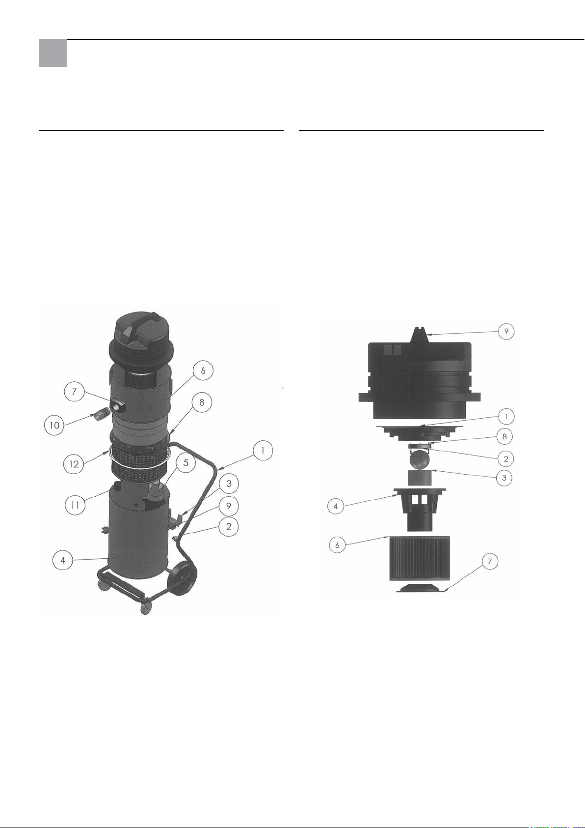
Hogedrukkrake 85 compleet:
Zuigkop:
Pos. Benaming Art. nr.
1 Onderstel compleet 65 80 11
2 Afstandstuk voor zuiger 65 80 16
3 Kantelvoorziening 65 77 47
4 Ketel onder compleet (zonder pomp) 65 80 08
5 Dompelpomp 65 77 17
6 Ketelkap compleet 65 80 09
7 Ketelkoppeling compleet,
inclusief instroomaansluitingen 65 80 13
8 Filterkorf 65 80 12
9 Kabelschroefverbinding
compleet Krake 85 65 80 17
11 Mof met terugslagklep 65 80 14
12 Dichting voor korf 65 77 20
Pos. Benaming Art. nr.
1 Motoropnameplaat 65 80 66
2 Dichting afsluitkogel 65 80 19
3 Filterzeef 65 80 73
4 Vlotterbehuizing 65 80 72
5 Afsluitkogel 65 80 21
6 Vouwlter C 65 77 25
7 Houder voor lterpatronen 65 80 75
8 Spaanplaatschroef 3 x 20 65 80 22
9 Zuigkop 2.400 W blauw compleet 65 80 20
20
Page 21
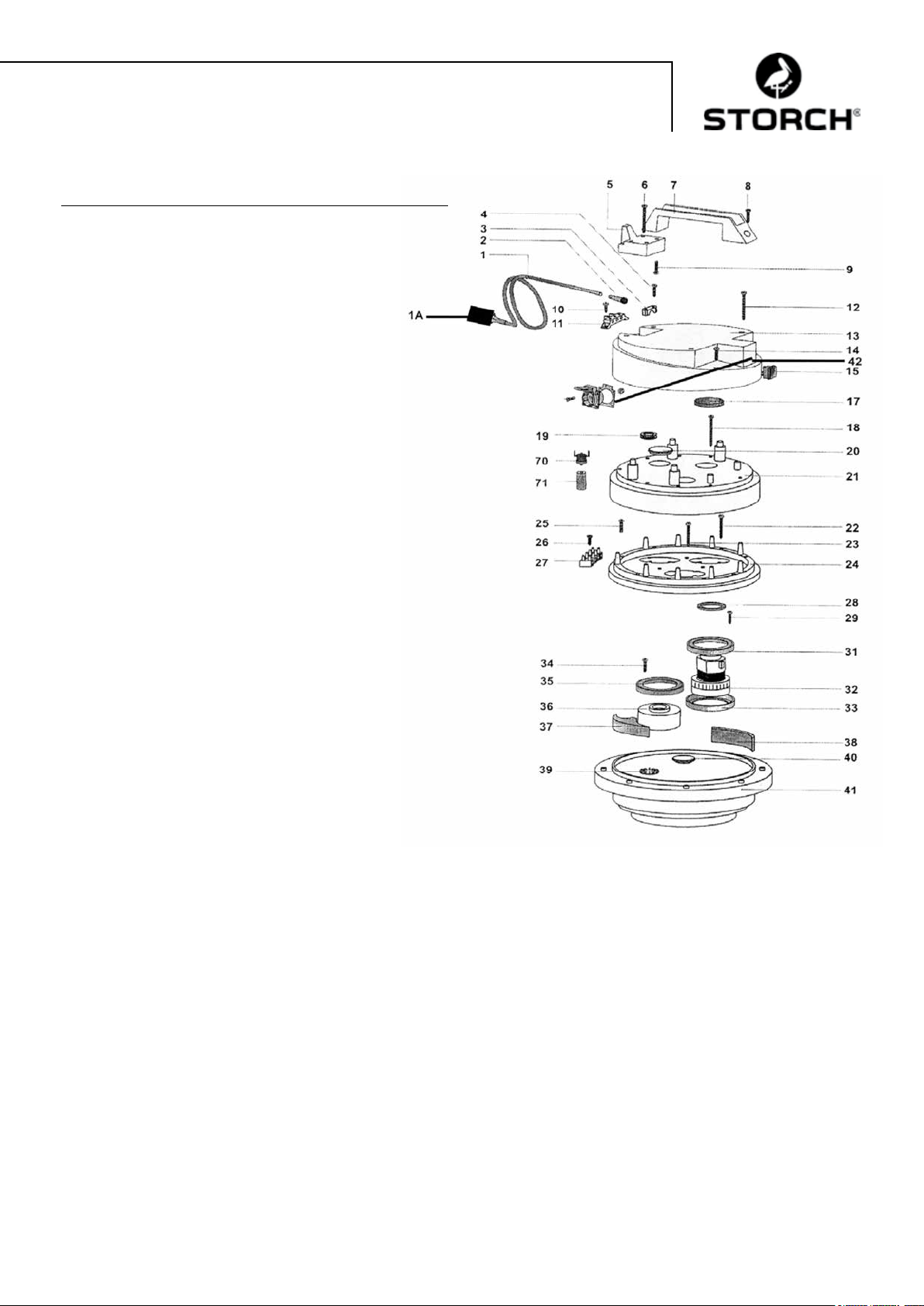
Zuigkop:
Pos. Benaming Art. nr.
1 Stroomkabel 2 x 1,5, met stekker 65 80 31
1a Persoonlijke bescherming-stekker IP 44 60 02 46
2 Kabelvoering voor zuigkop 65 80 33
3 Kabelklem voor zuigkop 65 80 34
4 Kruisschroef M 5 x 20 65 80 35
5 Kabelhouder voor zuigkop HDK 85 65 80 36
6 Schroef 5,2 x 50 65 80 37
7 Handgreep voor zuigkop HDK 85 65 80 38
8 Kruisschroef M 5 x 35 65 80 39
9 Kruisschroef M 5 x 20 65 80 35
10 Kruisschroef M 5 x 14, 65 80 41
11 Aansluitklem 65 80 42
12 Schroef 5,2 x 50 65 80 37
13 Behuizingsdeksel voor zuigkop 65 80 43
14 Kruisschroef M 5 x 20 65 80 35
15 Schakelaar aan / uit voor zuigkop 65 80 44
17 Filter voor zuigkop HDK 85 65 80 45
18 Schroef 5,2 x 50 65 80 37
19 Kabelbeschermring 65 80 47
20 Sluitplug 65 80 48
21 Motorafdekking voor zuigkop 65 80 49
22 Plaatschroef 3 x 40 65 80 51
23 Plaatschroef 3 x 40 65 80 51
24 Opnamering voor zuigkop 65 80 52
25 Kruisschroef M 5 x 30 65 80 53
26 Plaatschroef 4,3 x 19 65 80 54
27 Aansluitklem 4-polig 65 80 55
28 Dichtring 65 80 56
29 Kruisschroef M 5 x 20 65 80 35
31 Motordichting voor zuigkop 65 80 57
32 Motor voor HDK 85 65 80 03
33 Motordichting voor zuigkop 65 80 57
34 Kruisschroef M 5 x 20 65 80 35
35 Motordichting voor zuigkop 65 80 57
36 Afstandhouder 65 80 61
37 Dichtingsstuk voor zuigkop 65 80 62
38 Filter 65 x 10, L = 120 65 80 63
39 Koppelingsschijf 65 80 64
40 Afdekkap 65 80 65
41 Motoropnameplaat 65 80 66
42 Schuko-contact voor zuigkop 65 80 67
70 Thermoschakelaar voor HDK 85 65 80 07
71 Houder voor thermocontact 65 80 68
21
Page 22
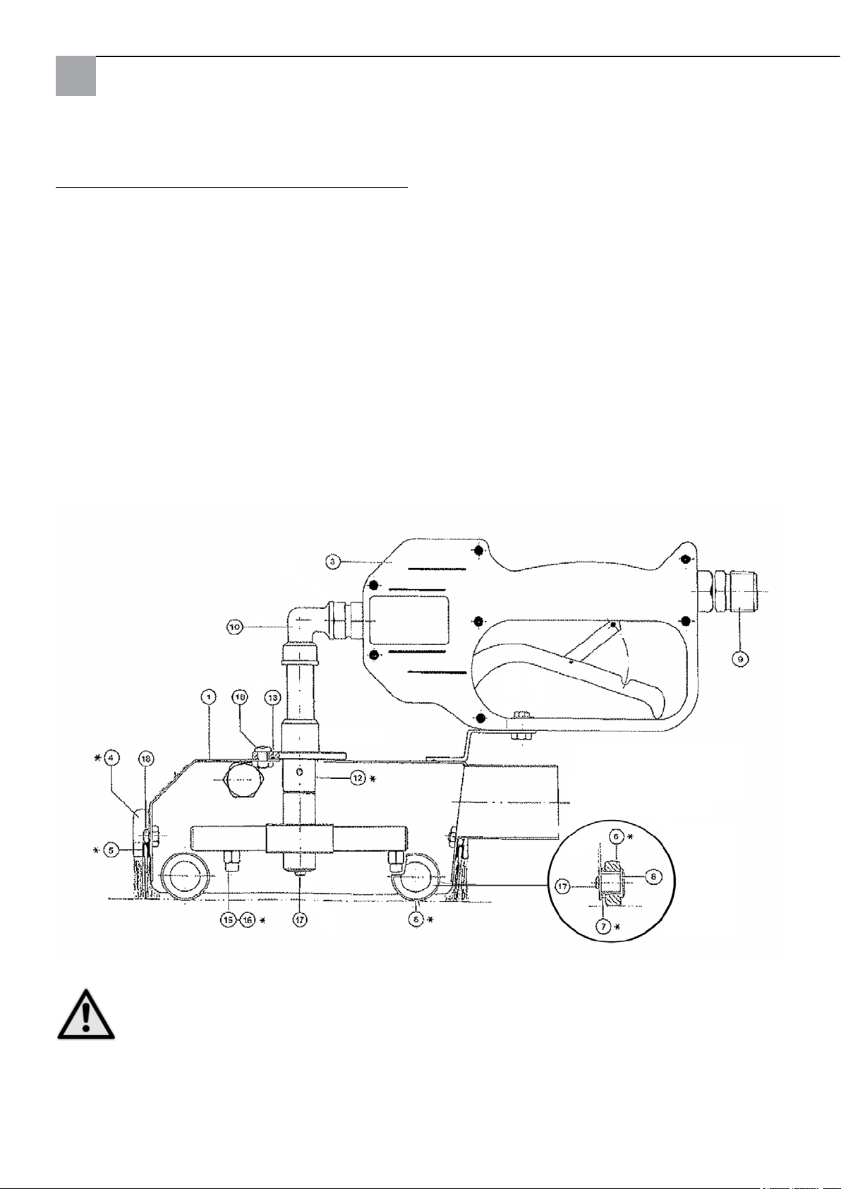
Vervangende onderdelen voor standaard reinigingskap:
Pos. Benaming Art. nr.
1 Kap 65 74 01
3 HD-afsluitventiel (nieuw) 65 71 30
4 Set afdichtingsborstels, 4-delig 65 74 18
6 Wieltje 65 74 04
7 Lagerbus 65 74 05
8 Lagerpen 65 74 06
9 Aansluitnippel 65 71 21
10 Hoek 90 graden 65 71 23
12 Wisseldeel puntstraal 65 75 51
12a Wisseldeel vlakke straal 65 75 52
15 Sproeier 0,95 65 74 08
16 Sproeier 1,27 (met groef) 65 74 19
17 Lenskopschroef M4 x 8 65 74 12
18 Lenskopschroef M5 x 10 65 74 13
niet afgebeeld:
Teonrollen breed 65 75 54
Thermometer met kleefring 65 75 53
* Slijtageonderdelen
OPGELET
Wij adviseren de bijgevoegde sproeiers met een 1,27 doorsnede te gebruiken, indien de hogedrukreiniger
meer dan 11 liter water per minuut transporteert.
22
Page 23

Toebehoren en vervangende onderdelen:
Benaming Art. nr.
Professionele hogedrukreiniger 135 bar 65 60 00
Professionele hogedrukreiniger 220 bar,
benzine 65 60 50
Verleng-hogedrukslang, compl., 10m 65 70 10
Verlengings-HD-slang, 10 m, drukbelasting tot
400 bar, max. temperatuurbelasting 150° C 65 65 14
Verlengings-HD-slang, 10 m, dubbele
verbindingsnippel, drukbelasting tot 210 bar,
max. temperatuurbelasting 150° C 65 65 30
Verbindingen met dubbele nippels
hogedrukslang M 22 x 1,5 65 65 31
Verleng-afvoerslang 10 m 65 70 16
Slanghouder 64 24 25
Reinigingskap voor kleine vlakken 6x6 cm 65 76 50
Reinigingskap voor grote vlakken 44x40 cm 65 75 60
Bodemreinigingsinstallatie voor reinigingskap
voor grote oppervlakken 65 75 80
Wateraanzuigsproeier voor opzuigen van water 65 10 30
Zuigpijp metaal 1,2 m 65 10 10
Benaming Art. nr.
Vervangende onderdelen afzuigapparaat:
Meerweg-doeklterzak 210 mµ 65 77 30
Meerweg-doeklterzak 300 mµ 65 77 31
Meerweg-doeklterzak 400 mµ 65 77 32
Koppeling voor zuigslang 65 70 11
23
Page 24

Garantie
Garantievoorwaarden
Voor onze apparaten gelden de wettelijke garantieperioden van 12 maanden vanaf aankoopdatum/factuurdatum van
de eindklant. Indien wij langere perioden in een garantieverklaring hebben toegezegd, dan worden deze speciaal in de
gebruiksaanwijzingen van de desbetreffende apparaten toegelicht.
Indienen van garantieclaims
Bij een garantieclaim vragen wij u het gehele apparaat samen met de rekening franco aan ons logistiekcentrum in Berka of naar een door ons geautoriseerd servicestation te verzenden.
Neem eerst contact op met de STORCH Service-Hotline (hiervoor worden kosten in rekening gebracht):
+49 (0)202 . 49 20 – 110.
Garantieclaims
Reparatieclaims gelden alleen voor materiaal- of fabricagefouten en alleen bij reglementair gebruik van het apparaat.
Slijtagedelen zoals afdichtingsborstels, loopwieltjes, luchtfilters, dichtingen, rototiespuitkoppen, herbruikbare filters
enzovoort vallen niet onder deze claims. Alle claims vervallen bij inbouw van onderdelen van externe herkomst, bij verkeerde hantering en opslag en bij het klaarblijkelijk niet in acht nemen van de gebruiksaanwijzing.
Reparaties uitvoeren
Reparaties mogen uitsluitend door onze fabriek of door STORCH geautoriseerde servicestations worden uitgevoerd.
24
Page 25
EG-conformiteitverklaring
Naam/adres van de opsteller: STORCH Malerwerkzeuge & Profigeräte GmbH
Platz der Republik 6 - 8
D - 42107 Wuppertal
conform EG-machinerichtlijn 2006/42/EG, bijlage II A
Hiermee verklaren we dat de volgende machine
Omschrijving van de machine: Hogedrukkrake 85
Machinetype: Natzuiger
Artikelnummer: 65 80 00
aan de geldende bepalingen van de volgende richtlijnen voldoet:
Machinerichtlijn: 2006 / 42 / EG
EMV-richtlijn: 2004 / 108 / EG
Verantwoordelijke voor samenstelling van de technische documentatie:
STORCH Malerwerkzeuge & Profigeräte GmbH
Platz der Republik 6 - 8
D-42107 Wuppertal
Holger Joest Jörg Heinemann
- Hoofd Productmanagement Techniek en Service - - Directeur -
Wuppertal, april 2012
25
Page 26

FR
Nous vous remercions
de la confiance dont vous témoignez envers STOCH. Avec cet achat vous avez opté pour un produit de
qualité. Si vous avez malgré tout des suggestions pour l‘amélioration ou si vous deviez rencontrer un problème, nous
sommes avec plaisir à votre disposition.
Dans ce cas, contactez votre représentant, ou directement notre service clients, s‘il s‘agit d‘un problème urgent.
Salutations dévouées
SAV STORCH
Tél.: +49 (0) 2 02 . 49 20 - 112
Fax: +49 (0)2 02 . 49 20 - 244
Ligne d‘assistance SAV gratuite: +49 800 7 86 72 47
Service gratuit de commande par téléphone: +49 800. 7 86 72 44
Fax de commande gratuit: +49 800. 7 86 72 43
(uniquement en Allemagne)
Sommaire Page
Caractéristiques techniques 26 - 27
Étendue des fournitures 27
Description du fonctionnement 27
Sigles de contrôle/Prescriptions relatives aux rejets 27
Mise en service 28
Pression de l'eau / température 28
Cloche de nettoyage 28
Flexible d'aspiration 29
Dispositif d'aspiration avec pompe immergée 29
Instructions importantes 29
Consignes de sécurité 30
Entretien / nettoyage 30
Diagnostic de défaut 31
Dessins détaillés 32 - 34
Accessoires et pièces de rechange 35
Dispositions de garantie 36
Déclaration de conformité 37
Caractéristiques techniques dispositif d'aspiration :
− Tension courant alternatif 230 V, 50 Hz
− Consommation de courant 1 moteur 5,5 A
− Consommation de courant 2 moteurs 11 A
− Fusible secteur 16 A
− Puissance moteurs d'aspiration 2 x 1.220 Watt
− Débit d'air max. 5 800 l/min
− Longueur exible d'aspiration max. 30 mètres
− Longueur câble de connexion max. 30 m, 2,5 mm², complètement enroulé
− Dimensions de l'appareil L 780 mm x l 525 mm x H 1.310 mm
− Poids 45 kg
− Niveau sonore 77 db (A)
Caractéristiques techniques pompe immergée :
− Courant alternatif 230 V, 50 Hz
− Consommation de courant 1,4 A
− Puissance absorbée 320 W
− Régime moteur 2.800 tr/min
− Hauteur manométrique 1 / 3 / 5 / 7 m
− Volumes 11 / 9 / 6 / 1 mètres cubes / h
26
Page 27
Caractéristiques techniques Cloche de nettoyage standard :
− Largeur totale 150 mm, longueur totale 340 mm, largeur de travail env. 110 mm
− Pression de travail 60 à 200 bar
− Alimentation en eau max. 20 l/min.
− Température d'eau max. 85° C.
Fourniture du collecteur haute pression STORCH-Krake 85 :
Cloche de nettoyage standard complet avec brosses d'étanchéité
Flexible haute pression 10 m
Tuyau d'aspiration 10 m
Flexible d'écoulement 10 m
Dispositif d'aspiration complet avec ltre, pompe d'immersion et bâti
Câble de connexion avec connecteur de protection FI
Mode d'emploi
CONTRÔLES RELATIFS À LA SÉCURITÉ :
RESPECTER LES DISPOSITIONS NATIONALES EN VIGUEUR.
Description générale du fonctionnement :
Avec le collecteur haute pression STORCH-Krake, l'eau projetée par un nettoyeur haute pression sur une façade (ou
d'autres surfaces, murs, plafonds, sols) est collectée immédiatement; les substances solides contenues dans les eaux
usées sont ltrées à partir d'un diamètre de particules de 0,21 mm de sorte que l'eau nettoyée puisse en règle générale
être menée dans un canal d'eaux usées (en fonction des disposition des autorités locales pour les eaux usées) dans le
respect de l'environnement. Le exible haute pression fourni est raccordé au nettoyeur haute pression et à la cloche de
nettoyage au moyen de laquelle l'eau est pulvérisée sur la surface à nettoyer au moyen d'une buse à rotation intégrée.
Un vide est généré dans la cloche de nettoyage par le dispositif d'aspiration de sorte que les eaux usées soient directement aspirées dans le dispositif d'aspiration sans que des quantités d'eau signicatives puissent d'échapper de la cloche
de nettoyage.
De cette manière, il est même possible de travail avec le nettoyeur haute pression à l'intérieur (par ex. dans les escaliers / les églises). Le dispositif d'aspiration peut être utilisé avec un ou deux moteurs selon la puissance d'aspiration
désirée. Les moteurs peuvent pour cela être commutés séparément au niveau des sectionneurs généraux. Les eaux
usées sont ltrées dans le dispositif d'aspiration avec un ltre (disponible avec les tailles de mailles 210 - 400 µm)
pour être ensuite pompées par une pompe immergée intégrée en continu via le exible d'écoulement.
ATTENTION
Il est interdit d'utiliser le nettoyeur haute pression Krake 85 dans la mesure où les matériaux devant être
traités sont assortis des avertissements de danger suivants :
Explosif facilement / extrêmement inammable
Les moteurs du nettoyeur haute pression Krake 85 ne sont pas à protection Ex et peuvent enammer des matériaux
identiés en conséquence. Tenir impérativement compte des ches techniques de sécurité du fabricant du matériau. Ne
jamais utiliser de matériaux dont le point de amme est inférieur à 21° C.
ATTENTION
il est interdit d'avoir un diamètre de tuyau d'évacuation inférieur à ¾“. L'appareil contient un filtre réutilisable de 400 µm à la livraison.
Symboles de contrôle / Prescriptions relatives aux rejets
IP44
27
Page 28
ATTENTION
Avant de rejeter les eaux usées dans le canal d'eaux usées, il est impératif de se procure une autorisation de
rejet des autorités compétentes pour les eaux. Utiliser uniquement des décapants biodégradables de la classe de mise en danger de l'eau I si vous souhaitez rejeter les eaux usées dans un canal d'eaux usées car les
décapants dissous ne peuvent pas être filtrés.
Le décapant « Radikalfresser » de la société Sikkens ne peut pas être traité avec cet appareil.
Mise en service du collecteur haute pression Krake de STORCH :
Les nettoyeurs haute pression et le dispositif d'aspiration doivent être raccordés à des circuits électriques séparés car le
dispositif d'aspiration absorbe env. 11 A d'électricité au total et de ce fait un circuit électrique sécurisé avec 16 A pourrait
être en surcharge suivant le nettoyeur haute pression utilisé. Disposer la tête d'aspiration avec la bague de réservoir
supérieure sur le ballon inférieur et toujours la connecter avec les 3 sauterelles ! Connecter le nettoyeur haute pressi-
on au moyen du flexible haute pression avec le cloche de nettoyage. Connecter la cloche de nettoyage et le dispositif
d'aspiration avec le flexible d'aspiration. Enficher le connecteur de la pompe immergée (extérieur sur le ballon) dans
la prise prévue à cet effet sur la tête d'aspiration. Contrôler si le dispositif d'aspiration incluant la pompe et le flexible
d'écoulement sont prêts à fonctionner. Mettre en service le nettoyeur haute pression et le dispositif d'aspiration (les
deux moteurs du collecteur haute pression Krake l'un après l'autre, pas simultanément, puis le nettoyeur haute pression) et mettre la cloche de nettoyage sur la surface à nettoyer. Actionner la poignée pistolet sur la cloche de nettoyage
et contrôler que la rotabuse tourne.
Pression et température d'eau
Ne pas appliquer une pression supérieure à 200 bar sur la cloche de nettoyage. Sélectionner la pression d'eau appropriée
pour le substrat sur le nettoyeur haute pression an de ne pas l'endommager. Utiliser pour les substrats mous (par ex. le
plâtre en intérieur) les larges rouleaux en plastique (inclus dans la fourniture) et la rotabuse avec le jet plat (accessoires).
La mise en oeuvre d'une Hot-Box (réf. 65 03 00) augmente la vitesse de progression du travail de jusqu'à 40 % avec de
l'eau chaude et l'efcacité de nettoyage est sensiblement améliorée.
ATTENTION
La température maximale d'eau réglée ne doit pas dépasser 85 °C. Un contrôleur de température coupe
l'aspirateur et la pompe immergée intégrée si la température est dépassée. Ils peuvent tous deux être remis
en service après une durée de refroidissement d'environ 15 minutes. Pour soutenir la période de refroidissement, ouvrir le dispositif d'aspiration en retirant la tête d'aspiration de la partie inférieur du ballon.
Cloche de nettoyage :
ATTENTION
Ne pas regarder ni mettre les mains dans la cloche ! Risque de blessure ! La poignée de maintien peut être
vissée soit à droite, soit à gauche au choix. Il est possible de régler les brosses d'étanchéité en hauteur
après avoir desserré les vis extérieures. Sur les surfaces lisses, les brosses d'étanchéité doivent être insérées
jusqu'à la butée. Si le sous-sol est rugueux, les brosses d'étanchéité sont sorties de l'équivalent des creux
dans le substrat. Régler les brosses d'étanchéité de telle manière qu'il ne sorte pas d'eau de la cloche et
qu'un mouvement fluide de la cloche de nettoyage sur le sol soit possible. La cloche de nettoyage est guidée
dans des voies verticales. La cloche peut toutefois également être déplacée légèrement sur le côté.
S'assurer que la cloche de nettoyage est dénuée d'encrassement à l'intérieur qui pourrait empêcher la rotation de la
rotabuse. Contrôler avant chaque prise de travail la sortie uniforme de l'eau des deux buses de la rotabuse et si celle-ci
tourne dans la cloche de nettoyage `du fait de la pression de l'eau de distribution (en aucun cas avec le nettoyeur haute
pression en service).
ATTENTION
Regarder pour cela latéralement dans la cloche de nettoyage, ne jamais regarder directement de front sur
la rotabuse et actionner simultanément la soupape manuelle ! Si l'eau ne sort pas uniformément des buses,
celles-ci doivent être nettoyées : dévisser les deux buses avec une clé plate DN 8 mm des bras porteurs et
nettoyer les alésages intérieurs avec soin. Actionner une nouvelle fois la soupape manuelle pour pouvoir rincer d'éventuelles particules de saleté des cadres porteurs.
28
Page 29
Eliminer les particules de salissures qui pourraient s'être incrustées dans les paliers des galets de glissement si ceux-ci ne
peuvent plus être tourner facilement.
Remarque:
Nettoyage régulier, soin et entretien après la n du travail évitent les défauts !
Flexible d'aspiration :
La longueur maximale du exible d'aspiration ne doit pas dépasser 30 m.. Ne pas utiliser des longueurs de exible plus
longues que nécessaires. Veiller que le exible d'aspiration doit toujours posé en voies droites et ne pende pas ni ne soit
plié.
A la n du travail, rincer sufsamment le exible an qu'il ne se bouche pas. Pour les travaux sur échafaudage, nous
recommandons d'accrocher le exible à l'échafaudage avec les supports de exible (réf. 64 24 25) pour le soulagement
de la contrainte.
Dispositif d'aspiration avec pompe immergée :
La tête d'aspiration est équipée d'une coupure automatique de l'aspiration qui interrompt cette dernière lorsque la proportion de substances solides est trop élevée dans le panier de ltrage, l'eau ne peut plus s'écouler du panier de ltre et le
niveau d'eau dans le panier de ltre a atteint la hauteur maximale.
ATTENTION
Arrêter immédiatement le travail, mettre l'appareil hors service et nettoyer le panier de filtrage.
Pour vider le ltre, desserrer les 3 sauterelles sur le ballon et disposer le couvercle de ballon à côté de ce dernier.
Il est maintenant possible de sortir confortablement le panier de soutien. Nettoyer le ltre réutilisable, le rincer et remonter
l'appareil dans l'ordre inverse. Lors de la remise en place du panier de soutien, veiller que la bague d'étanchéité soit propre
et étanchéie bien. Si le panier de ltrage se remplit déjà après peu de temps, il est recommandé de brosser le substrat
lors des travaux de nettoyage et de collecter la couche décollée avec une large spatule lors de travaux de décapage et/ou
de mettre en place un ltre réutilisable plus grossier dans le panier de ltrage. Nous proposons outre le ltre réutilisable
de série avec taille de mailles de 400 µm également des ltres réutilisables avec des tailles de maille supérieures.
Pour vidanger l'eau résiduelles du ballon, celui-ci peut être basculé. Bloquer tout d'abord les galets de roulement avant
sur le châssis an d'éviter un roulement involontaire du châssis.
La pompe immergé se met automatiquement en et hors service avec un commutateur à otteur.
Un contrôle de niveau de remplissage est inutile et des interruptions de travail par une vidange du réservoir sont évitées.
La pompe doit toutefois être alimentée en électricité par le biais de la prise sur la tête d'aspiration. A la première utilisation
ou après une période d'arrêt prolongée (semaines/mois), la pompe immergée peut former un tampon d'air de sorte qu'il
ne s'écoule pas d'eau dans la chambre de la pompe. Dans ce cas, s'assurer que la pompe est complètement dans l'eau.
Brancher la che électrique du collecteur haute pression Krake de STORCH dans une prise électrique reliée à la terre et
connecter le connecteur de la pompe avec la tête d'aspiration. La pompe démarre. Appuyer maintenant le otteur vers
le bas à la main (la pompe s'arrête), le maintenir un moment puis le relâcher (la pompe se remet en service). Renouveler
cette procédure jusqu'à ce qu'il s'écoule de l'eau.
ATTENTION
Instructions importantes :
− Le collecteur haute pression Krake STORCH doit uniquement être utilisé pour l'aspiration humide et pas
pour l'aspiration de matériaux poussiéreux et secs.
− La température maximale de l'eau ne doit pas dépasser 85° C.
− Avant le début du travail, contrôler impérativement si le connecteur de la pompe immergée est enchée
dans la tête d'aspiration.
− Les sauterelles sur le réservoir doivent être bien fermées.
− Les bouchons du exible d'aspiration doivent être immédiatement éliminés. On les identie par le régime
qui augmente de façon audible des moteurs et une puissance d'aspiration qui diminue. L'appareil doit être
immédiatement être mis hors service. A la n du travail, le exible d'aspiration doit être totalement vidé
et rincé.
− Contrôler régulièrement l'usure, l'encrassement et l'endommagement du ltre à air. Un ltre qui n'est pas
intact affecte la puissance et la sécurité de l'appareil.
− Un contrôle régulier de la coupure automatique de l'aspiration au niveau de la propreté et de l'accessibilité
ainsi que de l'endommagement des sphères et du joint (siège des sphères).
− Remplacement de pièces usées et non intactes.
Le respect de ces instructions importantes vous permettra de toujours disposer d'un appareil de travail able. Le nonrespect de ces points supprimer toute exigence en garantie pour des dommages en résultant.
29
Page 30
Consignes de sécurité :
Pour le travail avec les cloches de nettoyage, il est interdit de mettre les mains ou d'autres parties du corps
devant les buses sous pression ou dans le jet d'eau. Le levier à main de la vanne d'arrêt HP sur la cloche de
nettoyage ne doit pas être bloquée dans la position de mise en service. En cas d'interruption du travail et à
la fin du travail, le levier manuel de la vanne d'arrêt HP doit être sécurisé cotre un actionnement accidentel
(sortir le verrou de sécurité). La cloche de nettoyage ne doit pas être orientée vers des personnes : il existe
un risque de blessure par la pression de l'eau résiduelle y compris après la mise hors service du nettoyeur haute pression. Ne pas mettre les mains à proximité immédiate du jet haute pression, maintenir un écart d'au moins 30 cm. Si
l'appareil n'est pas utilisé (pauses de travail), couper le collecteur haute pression Krake et le nettoyeur haute pression et
relâcher la pression sur la cloche de nettoyage en retirant la soupape manuelle.
ATTENTION
Nettoyer ou retirer la rotabuse à l'intérieur de la cloche de nettoyage uniquement lorsque le exible haute
pression est démonté de la cloche de nettoyage. Risque de blessure !
ATTENTION Chaleur :
Pour les travaux avec de l'eau chaude, porter fondamentalement des équipements de protection appropriés (par
ex, gants, lunettes de protection, protection du crâne pour les travaux en hauteur). Nettoyer l'appareil immédiatement après la conclusion des travaux. Laisser l'aspirateur refroidir pendant encore env. 15 minutes avec la
tête d'aspiration enlevée. Lors des travaux avec l'eau chaude sur des échafaudages, veiller que personne d'autre
ne se trouve sur les étages inférieurs pour exclure tout risque d'ébouillantement.
ATTENTION
L'appareil ne doit pas :
− Être utilisé dans des endroits présentant des risques d'explosion ni aspirer des substances explosives.
Cela s'applique en particulier aux zones dans lesquelles uniquement des machines contrôlées selon B1 peuvent
être installées.
− Être utilisé pour aspirer des poussières nocives à la santé.
− Aspirer des uides inammables et des acides.
− Aspirer des uides contenant de l'huile ou non conducteurs.
− Aspirer des sources d'inammation.
− Être utilisé dans ltre pour l'aspiration de poussières.
ATTENTION Electricité :
Ne pas rouler sur le câble d'alimentation électrique, ni l'écraser ou le tirer violemment. Contrôler régulière-
ment le câble d'alimentation électrique de la pompe immergée et du dispositif d'aspiration pour détecter
tout endommagement. Si celui-ci est abîmé, il est interdit d'utiliser la machine. Il est interdit de modifier
l'exécution indiquée par le fabricant pour le remplacement des câbles d'alimentation ou de connexion. Les
couplages des éventuels câbles de rallonge utilisés doivent être protégés contre les projections d'eau. Veiller
à ne pas endommager la ligne de la pompe lors du nettoyage intérieur du ballon. Débrancher impérativement la fiche
électrique avant de procéder à tout travail d'entretien. Lors du nettoyage et de l'entretien de machines, lors du remplacement de pièces ou lors de la conversion dans une autre fonction de travail, mettre le sectionneur général sur "0" et
débrancher la fiche électrique. La machine doit uniquement être opérée par des personnes qui y ont été formées, et qui
ont en particulier été instruites des dangers et chargées expressément de son utilisation. Respecter les consignes de
sécurité et de prévention des accidents en vigueur sur le site d'utilisation de la machine.
La plage de tension de l'appareil présente un risque électrique pour les hommes et les animaux. Seules des personnes
autorisées sont habilitées à dévisser et / ou à démonter l'appareil. De même, les réparations et l'entretien sont exclusivement réservés à des électriciens qualiés et à des ateliers spécialisés agréés. L'exploitation de l'appareil se fait sous la
seule responsabilité et aux risques exclusifs de l'acheteur/l'utilisateur.
Entretien / nettoyage :
Après utilisation, basculer le reste de l'eau sale du ballon hors du dispositif d'aspiration. Toujours rincer le ballon à l'eau
propre. Enlever les pierres, les restes de peinture et les salissures de l'ouverture d'aspiration de la pompe immergée. Ne
pas fermer le ballon avec la tête d'aspiration après le nettoyage car les deux pièces doivent rester sèches.
Lors du nettoyage, contrôler également la cartouche de ltre à air d'appareil sous la tête d'aspiration pour détecter impuretés et endommagements. Pour garantir une coupure automatique de l'aspiration optimale avec le panier de ltrage
plein, il faut maintenir la sphère d'étanchéité se trouvant dans le panier de ltre à air propre ainsi que le panier de ltre
et le joint.
Rincer la cloche de nettoyage soigneusement à l'eau après chaque utilisation. Veiller également à un nettoyage sufsant
des brosses d'étanchéité. Les roues de roulement doivent être occasionnellement démontées pour enlever l'encrassement
des suspensions. Desserrer pour cela les vis latérales (retirer les brosses d'étanchéité auparavant).
30
Page 31

Diagnostic de défaut :
L'efficacité de nettoyage avec la cloche de nettoyage n'est pas suffisante :
• La rotabuse ne tourne pas
• Dépôts de tartre sur le corps de rotation
• Bloquées par de l'encrassement
• Tourner plusieurs fois à la main (mettre tout d'abord le NHP hors pression)
• Dévisser et nettoyer
• La rotabuse peut s'arrêter lors la pression d'eau augmente brutalement. Dans ce cas, actionner plusieurs fois la
poignée de blocage haute pression.
• Le nettoyeur haute pression produit-il sufsamment de pression ?
• L'alimentation en eau vers le nettoyeur haute pression est-elle sufsante ? (conduite d'alimentation toujours ¾“)
• La rotabuse est éventuellement usée et doit être remplacée.
• Il n'est pas pompé d'eau hors du dispositif d'aspiration :
• Tampon d'air dans la pompe
• L'alimentation électrique vers la pompe immergée est-elle enchée dans la tête d'aspiration ?
• La pompe immergée est dans la boue et ne peut pas aspirer d'eau
• Flexible d'écoulement plié.
• Puissance d'aspiration inexistante ou trop faible :
• Coupure automatique de l'aspiration car portion de produits solides trop haute dans le panier de ltrage
• Mise hors service de l'appareil par un thermorupteur (provoquée par la coupure automatique de l'aspiration / exib-
le d'aspiration plié ou qui pend / température d'eau trop élevée)
• Couvercle de ballon avec le moteur exactement sur la partie inférieure du ballon ?
• Contrôler la bague d'étanchéité sur le panier de ltrage entre les ballons pour détecter endommagement et encrassement
• Contrôler la connexion des exibles d'aspiration
• Un seul moteur d'aspiration enclenché
• Les roues de roulement ne tournent pas sur la cloche de nettoyage :
• Enlever les salissures entre palier et roue de roulement.
• Sortie d'eau de la cloche :
• Nettoyer ou remplacer les brosses d'étanchéité collées.
• Puissance d'aspiration trop basse
• Réglage en hauteur des brosses d'étanchéité erroné
• La coupure automatique de l'aspiration est active (nettoyer le panier de ltrage)
• L'extraction de la cloche de nettoyage ne se laisse pas extraire :
• Desserrer le blocage
• L'aspirateur se coupe :
• Mise hors service de l'appareil par un thermorupteur (provoquée par la coupure automatique de l'aspiration
• exible d'aspiration plié ou qui pend / température d'eau trop élevée)
• Contrôler l'alimentation électrique : le connecteur de protection FI est éventuellement actif. Utiliser exclusivement
• un câble de rallonge de section de 2,5 mm². La longueur maximale ne doit pas dépasser 30 m. Dérouler comp-
lètement le tambour à câble.
• Le ltre à air à plis sous l'aspirateur est mouillé et / ou encrassé.
• Contrôler si le connecteur de pompe est enché dans l'aspirateur (dans le cas contraire, le niveau d'eau monte et la
coupure automatique de l'aspiration commute).
• Mettre les moteurs individuellement en service.
• Raccorder tous les appareils aux divers circuits électriques.
• Contrôler l'alimentation électrique 230 V.
• Commuter les deux sectionneurs généraux en position "0", éliminer la cause du défaut et remettre l'appareil en
service apr`s une durée d'attente d'env. 5 min.
31
Page 32
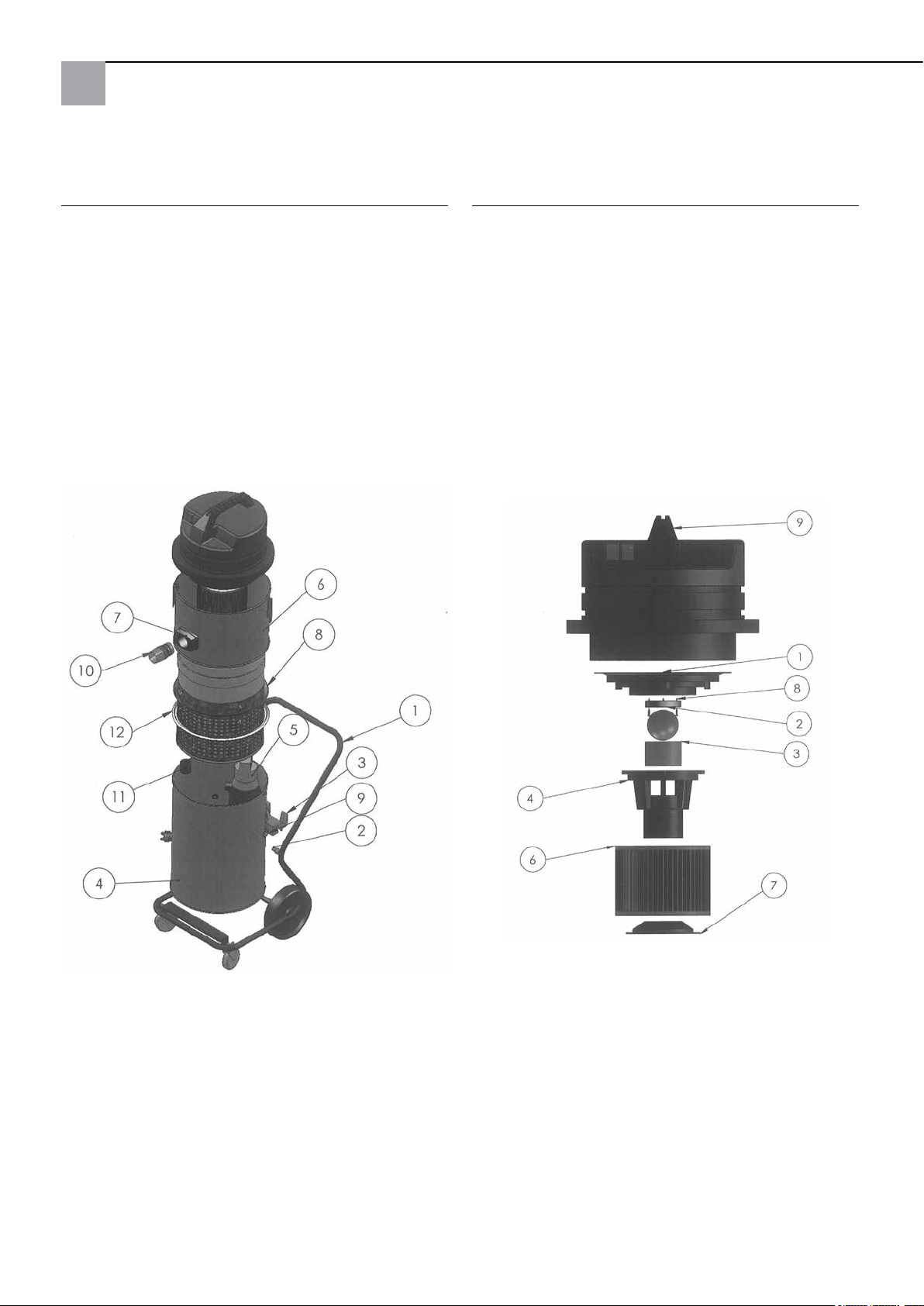
Collecteur haute pression Krake 85 complet : Tête d'aspiration :
Pos. Désignation Référence
1 Châssis complet 65 80 11
2 Pièce d'écartement pour la ventouse 65 80 16
3 Dispositif de basculement 65 77 47
4 Ballon inférieur complet (sans pompe) 65 80 08
5 Pompe submersible 65 77 17
6 Couvercle de ballon complet 65 80 09
7 Couplage de ballon complet y compris
tubulure d'admission 65 80 13
8 Panier support ltre 65 80 12
9 Passe-câble à vis complet Krake 85 65 80 17
11 Coquille avec clapet de retenue 65 80 14
12 Joint pour le panier de soutien 65 77 20
Pos. Désignation Référence
1 Plaque de réception du moteur 65 80 66
2 Joint bille de mise hors service 65 80 19
3 Filtre 65 80 73
4 Boîtier du otteur 65 80 72
5 Bille de mise hors service 65 80 21
6 Filtre à plis C 65 77 25
7 Support pour cartouche ltrante 65 80 75
8 Vis de plaque de serrage 3 x 20 65 80 22
9 Tête d'aspiration 2.400 W
bleue complète 65 80 20
32
Page 33
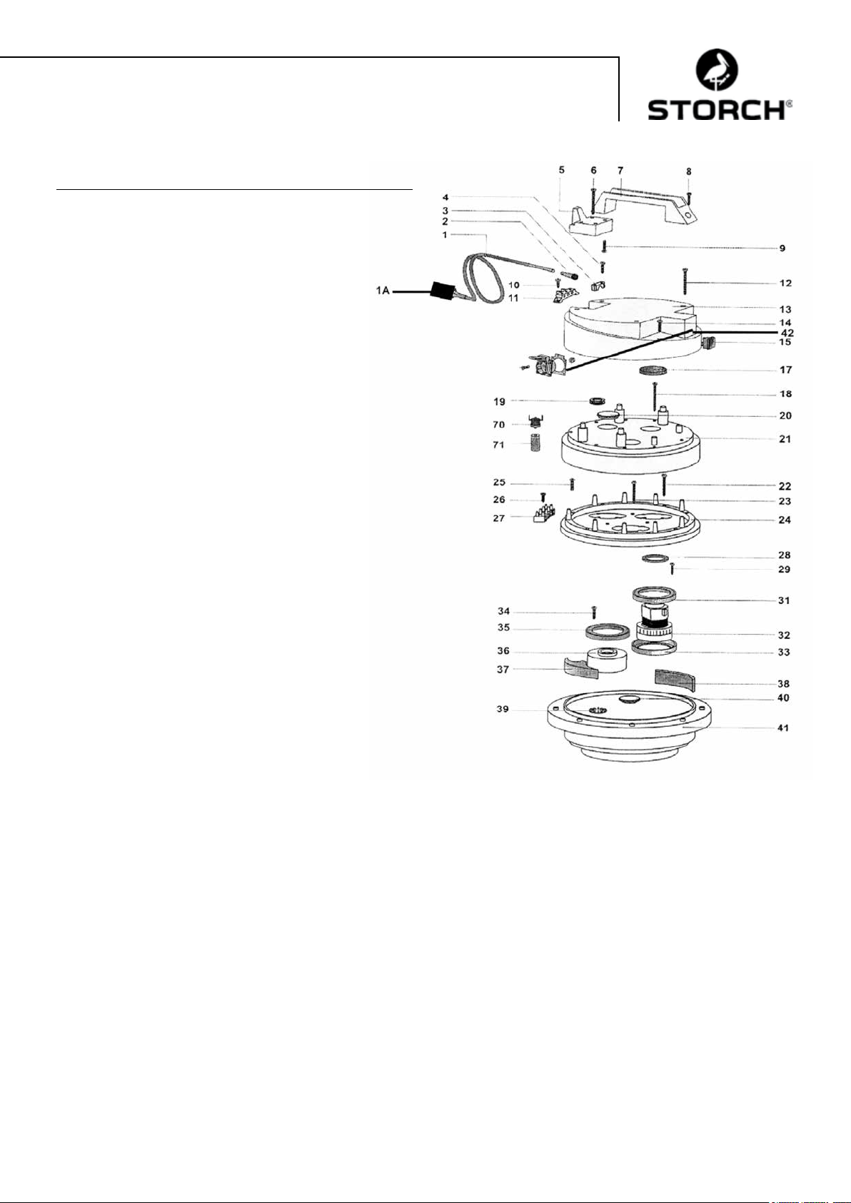
Tête d'aspiration :
Pos. Désignation Référence
1 Câble électrique 2 x 1,5,
avec connecteur 65 80 31
1a Fiche de protection des personnes IP 44 60 02 46
2 Guidage du câble pour tête d'aspiration 65 80 33
3 Borne de câble pour la tête d'aspiration 65 80 34
4 Vis croisée M 5 x 20 65 80 35
5 Support de câble pour tête d'aspiration
HDK 85 65 80 36
6 Vis 5,2 x 50 65 80 37
7 Poignée pour tête d'aspiration HDK 85 65 80 38
8 Vis croisée M 5 x 35 65 80 39
9 Vis croisée M 5 x 20 65 80 35
10 Vis croisée M 5 x 14 65 80 41
11 Borne de raccord 65 80 42
12 Vis 5,2 x 50 65 80 37
13 Couvercle de boîtier pour la tête
d'aspiration 65 80 43
14 Vis croisée M 5 x 20 65 80 35
15 Interrupteur marche / arrêt pour la
tête d'aspiration 65 80 44
17 Filtre pour tête d'aspiration HDK 85 65 80 45
18 Vis 5,2 x 50 65 80 37
19 Bague de protection du câble 65 80 47
20 Bouchon 65 80 48
21 Capot du moteur pour tête d'aspiration 65 80 49
22 Vis en tôle 3 x 40 65 80 51
23 Vis en tôle 3 x 40 65 80 51
24 Bague de réception pour la tête
d'aspiration 65 80 52
25 Vis croisée M 5 x 30 65 80 53
26 Vis en tôle 4,3 x 19 65 80 54
27 Borne de raccord à 4 pôles 65 80 55
28 Bague d'étanchéité 65 80 56
29 Vis croisée M 5 x 20 65 80 35
31 Joint moteur pour la tête d'aspiration 65 80 57
32 Moteur pour HDK 85 65 80 03
33 Joint moteur pour la tête d'aspiration 65 80 57
34 Vis croisée M 5 x 20 65 80 35
35 Joint moteur pour la tête d'aspiration 65 80 57
36 Ecarteur 65 80 61
37 Écarteur pour tête d'aspiration 65 80 62
38 Filtre 65 x 10, L = 120 65 80 63
39 Plateau d'embrayage 65 80 64
40 Cache 65 80 65
41 Plaque de réception du moteur 65 80 66
42 Prise à contact de protection pour la
tête d'aspiration 65 80 67
70 Thermorupteur pour HDK 85 65 80 07
71 Support pour contact thermique 65 80 68
33
Page 34
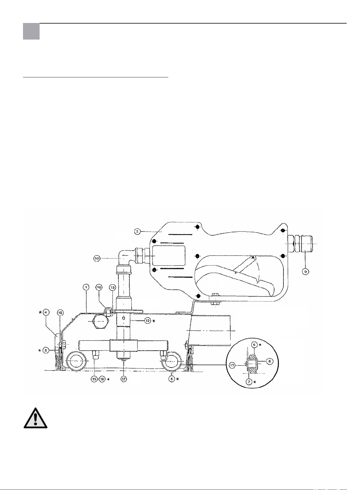
Pièces de rechange cloche de nettoyage standard
Pos. Désignation Référence
1 Capot 65 74 01
3 Soupape de retenue HD (neuve) 65 71 30
4 Jeu de brosses d'étanchéité, 4 pièces 65 74 18
6 Rouleau 65 74 04
7 Douille de palier 65 74 05
8 Tourillon de palier 65 74 06
9 Ajutage 65 71 21
10 Equerre 90 degrés 65 71 23
12 Pièce de remplacement jet en point 65 75 51
12a Pièce de remplacement jet plat 65 75 52
15 Buse 0,95 65 74 08
16 Buse 1,27 (avec rainure) 65 74 19
17 Vis à tête cylindrique bombée M4x8 65 74 12
18 Vis à tête cylindrique bombée M5x10 65 74 13
sans illustration :
Bobine de téon large 65 75 54
Thermomètre avec bague autocollante 65 75 53
* Pièces d'usure
ATTENTION
Nous recommandons la mise en oeuvre des buses jointes avec un diamètre de 1,27 mm, si le nettoyeur
haute pression utilisé débite plus de 11 l d'eau à la minute.
34
Page 35

Accessoires et pièces de rechange :
Désignation Référence
Nettoyeur haute pression professionnel
135 bar 65 60 00
Nettoyeur haute pression professionnel
220 bar, essence 65 60 50
Flexible d'aspiration de rallonge complet, 10 m 65 70 10
Flexible haute pression de rallonge, 10 m,
résistance à la pression jusqu'à 400 bar,
contrainte de température max.150 °C 65 65 14
Flexible haute pression de rallonge, 10 m,
incluant raccord double, résistance à la
pression jusqu'à 210 bar, contrainte de
température max. 150 °C 65 65 30
Assemblages à raccord leté double exible
haute pression M 22 x 1,5 65 65 31
Flexible d'écoulement de rallonge 10 m 65 70 16
Support de exible 64 24 25
Cloche de nettoyage de petites
surfaces 6 x 6 cm 65 76 50
Cloche de nettoyage de grandes
surfaces 44 x 40 cm 65 75 60
Dispositif de nettoyage du sol pour hotte
destinées aux surfaces importantes 65 75 80
Buse d'aspiration de l'eau pour aspirer de l'eau 65 10 30
Tube d'aspiration métallique 1,2 m 65 10 10
Désignation Référence
Pièces détachées pour aspirateur :
Sac de ltrage en tissu réutilisable 210 mµ 65 77 30
Sac de ltrage en tissu réutilisable 300 mµ 65 77 31
Sac de ltrage en tissu réutilisable 400 mµ 65 77 32
Couplage pour exible d'aspiration 65 70 11
35
Page 36

Garantie
Conditions de garantie
Les durées de garantie légales de 12 mois à compter de la date d'achat / de la facture du client final professionnels
s'appliquent à nos appareils. Si nous mentionnons des délais supérieurs dans le cadre d'une déclaration de garantie,
ceux-ci sont mentionnés dans les instructions de service des appareils concernés.
Exercice
Dans un cas couvert par la garantie, nous vous demandons de renvoyer l'appareil complet franco à notre centre logi-
stique à Berka accompagné de la facture ou de l'expédier à une station SAV agréée par nous.
Veuillez contacter préalablement l‘assistance téléphonique payante de la société STORCH: +49 (0)202 . 49 20 – 110.
Demande de prise en garantie
La garantie ne s'applique qu'en cas de défauts de fabrication ou de défaut des matériaux et exclusivement si l'appareil
a été utilisé conformément à l'usage prévu. Les pièces d'usure comme les brosses d'étanchéité, les roues de roulement,
le filtre à air, les joints, la rotabuse, le filtre réutilisable etc. ne sont pas couverts par la garantie. Tout droit à garantie
est rendu caduque par le montage de pièces qui ne sont pas d'origine, par une manipulation et un entreposage incorrects ainsi qu'en cas de non-respect évident des instructions de service.
Exécution de réparations
Toutes les réparations doivent exclusivement être réalisées par notre usine ou par des stations de SAV agréées par
STORCH.
36
Page 37
Déclaration de conformité CE
Nom / adresse de l'exposant : STORCH Malerwerkzeuge & Profigeräte GmbH
Platz der Republik 6-8
D - 42107 Wuppertal
Selon la directive Machines 2006/42 CE Annexe II A
Par la présente nous déclarons que la machine désignée ci-après
Dénomination de la machine: Collecteur haute pression Krake 85
Type de la machine: Aspirateur eau et poussières
Référence d'article: 65 80 00
satisfait aux dispositions applicables des directives suivantes :
Directive Machines: 2006 / 42 / CE
Directive CEM: 2004 / 108 / CE
Responsable de la compilation de la documentation technique :
STORCH Malerwerkzeuge & Profigeräte GmbH
Platz der Republik 6-8
42107 Wuppertal
Holger Joest Jörg Heinemann
- Responsable Product Management Technique et SAV - - Gérant -
Wuppertal, avril 2012
37
Page 38

IT
Grazie
per la fiducia accordata a STORCH. Con l‘acquisto avete scelto un prodotto di qualità. Se comunque avete dei
suggerimenti volti a migliorare la nostra offerta o se doveste incontrare qualche difficoltà, non esitate a rivolgerVi a noi.
Contattate il Vostro rappresentante oppure rivolgeteVi direttamente a noi in casi urgenti.
Distinti saluti,
STORCH Reparto Assistenza
Tel.: 02 - 66 22 77 15
Indice del contenuto Pagina
Dati tecnici 38 - 39
Materiale compreso nella fornitura 39
Descrizione delle funzioni 39
Marchio di controllo/ disposizioni per lo scarico dell'acqua reua 39
Messa in funzione 40
Pressione dell'acqua / Temperatura 40
Calotta detergente 40
Tubo di aspirazione 41
Dispositivo di aspirazione con pompa sommersa 41
Avvertenze importanti 41
Avvertenze di sicurezza 42
Manutenzione / Pulizia 42
Diagnosi errore 43
Disegni dettagliati 44 - 46
Accessori e pezzi di ricambio 47
Garanzia 48
Dichiarazione di conformità 49
Dati tecnici aspiratore:
− Tensione corrente alternata 230 V, 50 Hz
− Corrente assorbita 1 motore 5,5 A
− Corrente assorbita 2 motori 11 A
− Fusibile di rete 16 A
− Potenza motore di aspirazione 2 x 1.220 Watt
− Portata d'aria max. 5.800 l/min
− Lunghezza essibile di aspirazione max. 30 metri
− Lunghezza cavo di allacciamento max. 30 m, 2,5 mm², completamente dipanato
− Dimensioni del dispositivo lunghezza 780 mm x larghezza 525 mm x altezza 1.310 mm
− Peso 45 kg
− Livello rumore 77 db (A)
Dati tecnici pompa sommersa:
− Corrente alternata 230 V, 50 Hz
− Corrente assorbita 1,4 A
− Potenza assorbita 320 W
− Numero giri motore 2.800 rpm
− Portata 1 / 3 / 5 / 7 m.
− Volumi 11 / 9 / 6 / 1 metri cubi / ora.
38
Page 39
Dati tecnici Calotta detergente standard:
− Larghezza complessiva 150 mm, lunghezza complessiva 340 mm, raggio di azione ca. 110 mm
− Pressione di esercizio 60-200 bar.
− Alimentazione acqua max. 20 l/min.
− Temperatura acqua max. 85° C
Volume di consegna del detersore ad alta pressione 85 di STORCH:
Calotta detergente standard con spazzole di tenuta
Flessibile per alta pressione 10 m
Tubo di aspirazione 10 m
Tubo di scarico 10 m
Aspiratore completo di ltro, pompa sommersa e telaio con rotelle
Cavo di allacciamento con presa salvavite (FI)
Istruzioni per l'uso
CONTROLLI TECNICI DELLA SICUREZZA:
RISPETTARE LE RELATIVE DISPOSIZIONI NAZIONALI.
Descrizione generale del funzionamento:
Il detersore ad alta pressione STORCH consente di raccogliere immediatamente l'acqua proiettata a getto su una fac-
ciata (o supercie simile tipo parete, softta o pavimento), ltrando le sostanze solide contenute nell'acqua di scarico
a partire da un diametro di 0,21 mm, in modo che l'acqua ltrata generalmente può essere convogliata nel rispetto
dell'ambiente nella canalizzazione comunale (a seconda delle disposizioni locali in vigore per le acqua di scarico). Il
essibile per l'alta pressione fornito a corredo viene collegato al detersore ad alta pressione e alla calotta detergente, la
quale proietta l'acqua, tramite la fresa detergente rotante integrata, sulla supercie da nettare. Il dispositivo di aspirazione crea un vuoto nella calotta detergente, in modo che l'acqua reua viene aspirata tramite il essibile di aspirazione
direttamente dall'aspiratore, senza che si verichino delle fuoriuscite d'acqua dalla calotta detergente degne di nota.
In tal modo l'idropulitrice ad alta pressione si può impiegare senza remore anche in ambienti chiusi (ad es. tromba delle
scale / chiese). In base alla potenza richiesta l'aspiratore può essere azionato con uno o con due motori. Inoltre, i motori
possono essere azionati l'uno indipendentemente dall'altro. Un ltro (disponibile da 210 - 400 mµ) all'interno dell'aspiratore depura l'acqua che viene quindi estratta dalla pompa sommersa integrata in modo continuo tramite il essibile di
aspirazione.
ATTENZIONE
L'uso del detersore ad alta pressione della serie 85 non è consentito in concomitanza con materiali e sostanze che presentano le seguenti caratteristiche in termini di rischi:
Esplosivo Altamente / Facilmente inammabile
Il detersore ad alta pressione della serie 85 non è dotato di motori antideagranti e può quindi inammare materiali e
sostanze inammabili. Attenersi assolutamente alla scheda di sicurezza del produttore del materiale o della sostanza.
Non impiegare in nessun caso con materiali o sostanze con un punto di inammabilità inferiore a 21° C.
ATTENZIONE
Il diametro del flessibile di scarico non deve essere inferiore a ¾". Il dispositivo viene fornito con un filtro di
400 my riutilizzabile in dotazione.
Marchio di controllo/ Norme di smaltimento
IP44
39
Page 40
ATTENZIONE
Prima di immettere l'acqua sporca nella canalizzazione comunale, va fatta comunque la richiesta di nullaosta presso l'autorità locale competente. Utilizzate esclusivamente decapanti biodegradabili appartenenti alla
categoria I di sostanze inquinanti per l'acqua, se intendete immettere le acque reflue nella canalizzazione
comunale, dato che non è possibile filtrare il decapante contenuto nell'acqua. Altrimenti, attenendovi alle
disposizioni locali per il trattamento delle acque reflue, si dovrà provvedere eventualmente alla raccolta in
cisterne e allo smaltimento dell'acqua sporca.
Non utilizzate il decapante "Radikalfresser" della ditta Sikkens con la presente attrezzatura.
Messa in funzione del detersore ad alta pressione STORCH
Connettere l'idropulitrice ad alta pressione e l'aspiratore a due circuiti elettrici diversi, visto che l'aspiratore richiede una
alimentazione di circa 11 A ed a seconda dell'idropulitrice ad alta pressione utilizzata, si corre il rischio di sovraccaricare un circuito con una capacità di 16 A. Riporre l'anello superiore della testata di aspirazione sul serbatoio inferiore ed
eseguire sempre il collegamento servendosi dei 3 tenditori! Collegare il detersore ad alta pressione tramite l'apposito
flessibile alla calotta detergente. Collegare a questo punto la calotta detergente e l'aspiratore tramite il flessibile di
aspirazione. Inserire la spina della pompa sommersa (sull'esterno del serbatoio) nella presa prevista della testata di
aspirazione. Verificare l'aspiratore, la pompa ed il flessibile di scarico sono pronti per l'uso. Accendete l'aspiratore e
l'idropulitrice ad alta pressione (i due motori del detersore l'uno dopo l'altro - non contemporaneamente, ed in seguito
l'idropulitrice) e posizionate la calotta detergente sulla superficie da ripulire. Azionate il grilletto del revolver pulitore
della calotta detergente e verificate se gira la fresa detergente.
Pressione e temperatura dell'acqua:
Il valore massimo consentito per la calotta detergente è di 200 bar. Selezionate la pressione del getto d'acqua in base
alla supercie da ripulire, in modo da evitarne il danneggiamento. In caso di fondi sensibili (ad es. intonaco in ambienti
chiusi) utilizzate i larghi rulli in materiale plastico forniti a corredo e la fresa detergente a getto d'acqua ad angolatura
piana (accessori). Ricorrendo alla cosiddetta Hot-Box (cod. art. 65 03 00) si riesce quasi a dimezzare i tempi richiesti per
l'operazione di pulitura, dato che l'impiego di acqua calda ne incrementa in modo considerevole il grado di efcacia.
ATTENZIONE
La temperatura dell'acqua impostata non deve superare 85°C. Un dispositivo di controllo automatico della
temperatura disattiva l'aspiratore e la pompa sommersa integrata, se si supera una determinata soglia di
temperatura. Dopo un lasso di tempo di circa 15 min. per il raffreddamento, è possibile riaccendere aspiratore e pompa sommersa. Per agevolare il raffreddamento, aprite l'aspiratore, rimuovendo la testata di aspirazione dalla parte inferiore del serbatoio.
Calotta detergente:
ATTENZIONE
Non guardate direttamente nella calotta e non introducetevi le vostre mani! Pericolo di lesioni! L'impugnatura
può essere avvitata, a scelta, sulla destra o sulla sinistra. Le spazzole di tenuta possono essere regolate per
quanto riguarda la loro altezza, allentando le viti esterne. In caso di superfici lisce, le spazzole di tenuta
dovrebbero essere ritratte sino all'arresto. In caso di superfici ruvide, la loro sporgenza si orienterà alle caratteristiche del fondo da trattare. Le spazzole di tenuta vanno impostate in modo da non consentire delle fuo-
riuscite d'acqua della calotta ed in modo da permettere un azionamento scorrevole della calotta detergente.
La calotta detergente va movimentata in direzione verticale. È comunque data la possibilità di spostare la calotta anche
in senso leggermente laterale.
Assicurate che la calotta detergente all'interno non presenti delle impurità che potrebbero essere da ostacolo alla rotazione
della fresa. Prima di iniziare i lavori, vericate la regolarità del getto d'acqua da entrambi gli ugelli della fresa rotante
come anche se sotto la spinta della pressione dell'acqua la resa detergente ruota (non eseguite mai questo controllo con
l'idropulitrice ad alta pressione accesa).
ATTENZIONE
In questo caso, guardate nella calotta di sbieco, non guardate mai in modo diretto e frontale sulla fresa
rotante ed azionate nel contempo la valvola manuale! Se il getto d'acqua non risulta essere regolare, disin-
tasare gli ugelli: svitare entrambi gli ugelli, servendosi di una chiave fissa (apertura 8 mm), dalla struttura
portaugelli e pulire accuratamente i fori. Azionare ancora la valvola manuale per spurgare eventuali impurità
dal telaio portaugelli. Riavvitare quindi gli ugelli e serrarli bene servendosi di una chiave fissa.
Rimuovere le impurità che eventualmente si sono accumulate nei cuscinetti delle rotelle di scorrimento, se il loro movimento dovesse risultare non essere più scorrevole.
40
Page 41
Indicazione:
Pulitura ed interventi di manutenzione ad intervalli regolari dopo ogni ciclo di lavoro evitano il vericarsi di malfunzionamenti!
Tubo essibile di aspirazione:
La lunghezza max. del essibile di aspirazione non deve superare i 30 m. Non utilizzare dei essibili che siano più lunghi
del richiesto. Assicurare che il essibile venga dispiegato in modo rettilineo ed evitare che si etti e/o che si verichino
dei ripiegamenti verso il basso.
A conclusione del ciclo di lavoro, spurgare nel modo dovuto, per evitare ostruzioni. Per lavori su ponteggi si consiglia, ai
ni di una riduzione della forza di trazione, di ricorrere a delle staffe di appoggio per il essibile di aspirazione (cod. art.
64 24 25).
Aspiratore con pompa sommersa:
La testata di aspirazione è dotata di un dispositivo di interruzione di corrente, che ne interrompe il funzionamento, qualora vi fosse una presenza eccessiva di sedimenti nel raccoglitore del ltro che non permetta all'acqua di deuire e che si
raggiunga il livello max. previsto per l'acqua
ATTENZIONE
In questo caso, va interrotto il ciclo di lavoro, spento il dispositivo e pulito il raccoglitore del filtro.
Per svuotare il ltro, allentare le tre serrature del serbatoio e prelevare l'innesto dal serbatoio. A questo punto
estrarre comodamente il contenitore di appoggio. Pulire il ltro riutilizzabile e riassemblare il dispositivo seguendo
la procedura inversa. Assicurare in questa fase il corretto e dovuto posizionamento della guarnizione! Se il raccoglitore del
ltro dovesse riempirsi già entro breve tempo dall'operazione di pulitura, si consiglia di spazzolare inoltre il fondo ed, e se
si sono eseguiti dei lavori che interessano delle sostanze decapanti, rimuovere con una spatola larga lo strato formatosi
e/o utilizzare un ltro riutilizzabile più robusto nel raccoglitore del ltro. Oltre ai ltri riutilizzabili di serie con 400 mµ,
offriamo anche ltri riutilizzabili con una larghezza delle maglie più ampia.
Per togliere anche gli ultimi residui di acqua dal serbatoio, lo si può ribaltare. Occorre bloccare prima le rotelle anteriori
del telaio per evitare che si metta accidentalmente in movimento.
La pompa sommersa viene attivata e disattivata automaticamente tramite un interruttore a galleggiante.
Non dovendo controllare di continuo il livello dell'acqua, si evitano delle interruzioni del processo lavorativo per dover svuotare il serbatoio. La pompa deve essere comunque alimentata tramite la presa preposta alla testata di aspirazione. Durante
la prima messa in funzione oppure in seguito ad un periodo relativamente lungo (settimane/mesi) in cui il dispositivo è
rimasto inutilizzato, nella pompa sommersa può formarsi un cuscinetto d'aria in modo da impedire il usso dell'acqua nella
camera della pompa. In tal caso assicurare che la pompa sia completamente immersa nell'acqua. Inserire quindi la spina
di alimentazione dell'idropulitrice ad alta pressione di casa STORCH in una presa collegata a massa e connettere la presa
la spina della pompa con la testata di aspirazione. La pompa parte. Premete a questo punto manualmente il galleggiante
verso il basso (la pompa si spegne), mantenetelo per un po' di tempo in tale posizione e quindi rilasciatelo (la pompa si
riaccende). Ripetete tale procedimento afnché l'acqua sia stata estratta del tutto.
ATTENZIONE
Avvertenze importanti:
− Il detersore ad alta pressione STORCH è stato ideato esclusivamente per l'aspirazione ad umido e non può
essere utilizzata per aspirare sostanze asciutte e polverose.
− La temperatura dell'acqua massima non può superare gli 85°C.
− Prima di ogni ciclo di lavoro, controllare assolutamente che la spina della pompa sommersa sia inserita
nella testata di aspirazione.
− I tenditori del contenitore devono essere saldamente serrati.
− Rimuovere immediatamente degli intasamenti che interessano il essibile di aspirazione. Gli intasamenti
sono udibili a causa di un incremento del numero di giri dei motori e deterioramento della potenza di aspirazione. In queste situazioni, spegnere immediatamente il dispositivo. Alla ne del ciclo di lavoro, il essibile di aspirazione va completamente svuotato e spurgato.
− Eseguire dei controlli ad intervalli regolari del ltro dell'aria e vericare l'eventuale presenza di segni di
usura, impurità o danneggiamenti. Un ltro in uno stato non ineccepibile ha degli effetti negativi sulla
performance e stato di sicurezza del dispositivo.
− Controllare ad intervalli regolari che il dispositivo di interruzione di corrente della testata di aspirazione
sia pulito e funzionante nonché la presenza di danneggiamenti della sfera e guarnizione (posizionamento
corretto della sfera).
− Ricambio di componenti logori e non intatti.
Osservando queste avvertenze importanti disporrete sempre di un mezzo di lavoro afdabile. In caso di non osservanza
di queste indicazioni, decade il diritto alla garanzia per eventuali danni vericatesi.
41
Page 42
Avvertenze di sicurezza:
Nell'eseguire dei lavori con la calotta detergente è vietato portare le mani o altre parti del corpo davanti
agli ugelli sotto pressione o getto d'acqua. La leva manuale della valvola di chiusura ad alta pressione della calotta detergente non va bloccata nella posizione di esercizio attivato. In caso di interruzione o fine dei
lavori occorre bloccare la leva manuale proteggendola così da eventuale attivazione accidentale (azionare il
blocco di sicurezza). Non volgere la calotta di detersione verso persone; nemmeno dopo avere disattivato il detersore,
visto che vi è il pericolo di lesioni a causa dell'acqua ancora sotto pressione. Non mettere le mani nelle immediate vicinanze del getto d’acqua ad alta pressione, mantenendo in ogni caso una distanza di almeno 30 cm. Nei momenti in cui
il dispositivo non viene utilizzato (pausa lavoro), spegnete il detersore e ad alta pressione e l'idropulitrice ad alta pressione e alleviate la pressione della calotta detergente azionando la valvola manuale.
ATTENZIONE
Pulire o rimuovere la fresa rotante all'interno della calotta detergente solamente se il essibile per il convoglio
d'acqua ad alta pressione è staccato dalla calotta detergente. Pericolo di lesioni!
ATTENZIONE Calore:
Se si lavora con acqua calda, indossare indumenti protettivi, (come guanti, occhiali di protezione o un copricapo
adeguato nel caso di lavori da eseguire sopra la testa). Non pulire l'attrezzo immediatamente dopo aver concluso il ciclo di lavoro. Far raffreddare l'aspiratore per circa 15 min., dopo aver tolto la testata di aspirazione.
Far attenzione, nel caso in cui si utilizza dell'acqua calda su ponteggi, che al di sotto non vi siano delle persone
esposte al rischio di ustione.
ATTENZIONE
Il dispositivo non deve:
− essere utilizzato in luoghi esposti al rischio di esplosioni ovv. per aspirare dei materiali a rischio di es-
plosioni. Questo vale in modo particolare in luoghi, in cui è consentito impiegare esclusivamente macchinari
appartenenti alla categoria B1.
− essere impiegato per aspirare polveri dannose alla salute.
− aspirare liquidi ed acidi inammabili.
− aspirare liquidi oleiferi o non conducenti.
− essere utilizzato per aspirare fonti inammabili.
− essere utilizzato senza ltro come aspirapolvere.
ATTENZIONE Elettricità
Le condutture di allacciamento alla rete di erogazione non devono essere calpestate, schiacciate né tanto
meno sollecitate da trazione. Le condutture di allacciamento alla rete di erogazione della pompa sommersa
e dell'aspiratore vanno controllate a regolari intervalli di tempo, per rilevare la presenza eventuali danneg-
giamenti. Non impiegare l'attrezzo nel caso condutture di allacciamento a rete dovessero essere difettose.
La sostituzione di apparecchiature di allacciamento alle macchine o alle reti di erogazione non deve alterare la struttura realizzata dal costruttore. I raccordi ad innesto delle eventuali prolunghe devono essere provvisti di guarnizioni
antispruzzo. Fare attenzione in sede di pulitura all’interno del serbatoio di non danneggiare la conduttura della pompa.
Prima di dar luogo a qualsiasi operazione di manutenzione è assolutamente necessario staccare la spina dalla rete di
erogazione. Durante i lavori di pulizia o di manutenzione di macchinari, sostituendo dei componenti oppure convertendo
delle funzioni, bisogna portare in posizione ”0” l’interruttore generale e disinnestare la spina dalla presa. L'apparecchio
può essere usato solo da personale qualificato, addestrato e soprattutto al corrente circa i rischi a cui si va incontro
durante il suo impiego, e a cui è stata data apposita autorizzazione. Osservare le disposizioni in materia di sicurezza e
di anti-infortunistica sul lavoro da applicare nel luogo in cui si trova il macchinario.
L'apparecchio ha componenti elettriche che possono comportare un pericolo elettrico per persone ed animali. Esso deve
essere svitato e / oppure smontato solamente da persone autorizzate. Inoltre, i lavori di manutenzione e riparazione
devono essere eseguiti solo da elettricisti specializzati e ofcine specializzate. L'utilizzo dell'attrezzo avviene sotto la
responsabilità ed a pericolo dell'acquirente / utente.
Manutenzione / Pulitura :
Ultimato il ciclo di lavoro, versare il residuo dell’acqua sporca dal serbatoio dell’aspiratore. Risciacquarlo con acqua limpida. Rimuovere pietre, residui cromatici e sporcizia dal bocchettone di aspirazione e d’ingresso della pompa sommersa.
Non richiudere il serbatoio dopo la pulitura riponendovi la testata di aspirazione, per dare modo alle due componenti di
asciugare.
In sede di pulitura controllare anche se la cartuccia ltrante dell'aria del dispositivo posta sotto la testata di aspirazione
sia danneggiata o sporca. Per assicurare un funzionamento ineccepibile del dispositivo di interruzione automatica della
corrente, anche in caso di raccoglitore del ltro pieno, la sfera di ritenuta contenuta nel raccoglitore del ltro dell'area
come anche il raccoglitore del ltro e la guarnizione vanno mantenuti privi di sporcizia.
Dopo l'uso, la calotta detergente va risciacquata a fondo con acqua limpida. Badare che le spazzole di ritenuta siano
pulite a sufcienza. All’occorrenza smontare le rotelle di scorrimento per togliere la sporcizia dai cuscinetti. Allentare a
tal riguardo le apposite viti laterali (rimuovere prima le spazzole di ritenuta).
42
Page 43

Diagnosi del guasto:
L'azione detergente della calotta è insufficiente:
• La fresa rotante non gira
• Depositi di calcare al corpo rotante
• Blocco dovuto a sedimenti di impurità
• Girare più volte manualmente (disattivare prima l'idropulitrice)
• Disassemblare e pulire
• In caso di improvviso aumento della pressione dell'acqua, può aversi il blocco della fresa antisporco. In questi casi
azionare più volte il grilletto di arresto dell'idropulitrice.
• L'idropulitrice ad alta pressione genera abbastanza pressione?
• L'acqua convogliata all'idropulitrice è sufciente? (Tubo di alimentazione sempre ¾“)
• Eventual. la fresa rotante è logora e va sostituita
• L'acqua non viene estratta dall'aspiratore:
• Cuscinetti d'aria nella pompa
• La spina per la pompa sommersa è inserita nella testata di aspirazione?
• Pompa bloccata da fango non riesce ad aspirare l'acqua
• Flessibile di scarico piegato.
• Nessuna o insufciente potenza di aspirazione:
• Interruzione della corrente di aspirazione a causa dell'eccessivo contenuto di sedimenti nel raccoglitore del ltro
• Disattivazione dell'apparecchio attraverso il termostato (dovuto a interruzione della corrente di aspirazione / intasa-
mento, essibile di aspirazione piegato / temperatura dell'acqua troppo elevata)
• L'innesto del serbatoio con motore poggia correttamente sul fondo sulla parte inferiore del serbatoio?
• Vericare la presenza di danneggiamenti o impurità che interessano l'anello di tenuta del raccoglitore del ltro tra i
serbatoi
• Vericare l'allacciamento dei essibili di aspirazione
• E' acceso solo un motore di aspirazione
• Rotelle di scorrimento della calotta non girano:
• Rimuovere le impurità tra cuscinetto e rotella di scorrimento.
• Fuoriuscita d'acqua dalla calotta:
• Pulire o sostituire spazzole di tenuta appiccicate.
• Insufciente potenza di aspirazione
• Errata impostazione dell'altezza delle spazzole di tenuta
• Dispositivo di interruzione automatica attivato (pulire raccoglitore del ltro)
• Impossibile rimuovere il grilletto della calotta:
• Sbloccare l'arresto
• L'aspiratore si spegne:
• Disattivazione dell'apparecchio attraverso il termostato (dovuto a interruzione della corrente di aspirazione,
• essibile di aspirazione intasato, piegato, oppure temperatura dell'acqua troppo elevata)
• Controllare l'alimentazione di corrente: forse è attivato la presa salvavite (FI). Utilizzare esclusivamente
• un cavo di prolunga dello spessore di 2,5 mm². La lunghezza non può superare i 30 metri. Dipanare completamen-
te il cavo dal tamburo per cavi.
• Pieghe - ltro d'aria sotto l'aspiratore bagnato e / o sporco
• Vericare se la spina della pompa è inserita nell'apposita presa dell'aspiratore (altrimenti il livello dell'acqua sale e
si ha un'interruzione della corrente).
• Attivare i motori singolarmente.
• Connettere i dispositivi a circuiti elettrici diversi.
• Vericare l'alimentazione di corrente a 230 V.
• Portare entrambi gli interruttori principali sulla posizione "0", rimuovere la causa del guasto e riaccendere il dispo-
sitivo dopo aver fatto trascorrere cinque minuti.
43
Page 44
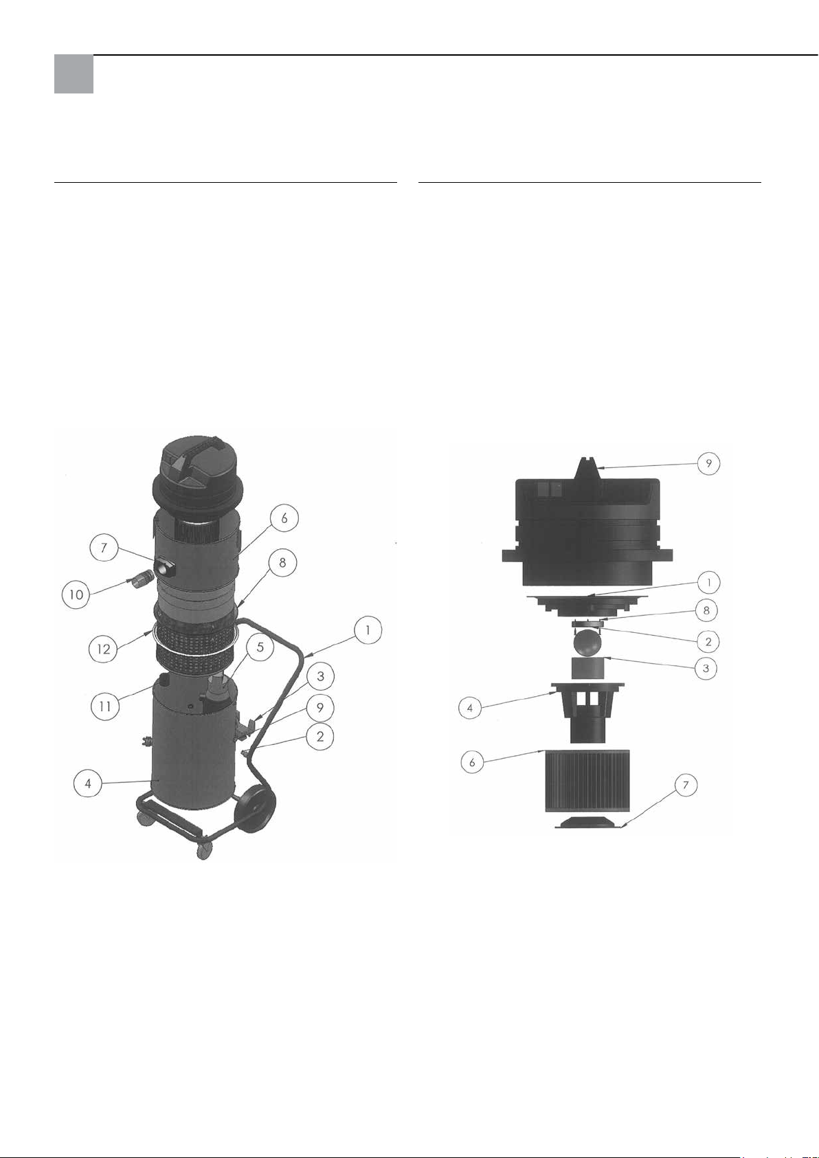
Detersore ad alta pressione 85, completo:
Testa aspiratrice:
Pos. Descrizione N. art.
1 Carrello, completo 65 80 11
2 Distanziatore per aspiratore 65 80 16
3 Dispositivo di ribaltamento 65 77 47
4 Serbatoio inferiore, completo
(senza pompa) 65 80 08
5 Pompa sommergibile 65 77 17
6 Innesto del serbatoio completo 65 80 09
7 Giunto per serbatoio, completo,
compreso raccordo di entrata 65 80 13
8 Contenitore di appoggio ltro 65 80 12
9 Passacavo completo detersore 85 65 80 17
11 Manicotto con valvola di ritegno 65 80 14
12 Guarnizione per contenitore di appoggio 65 77 20
Pos. Descrizione N. art.
1 Piastra di fermo motore 65 80 66
2 Guarnizione per sfera di spegnimento 65 80 19
3 Setaccio per ltro 65 80 73
4 Scatola del galleggiante 65 80 72
5 Sfera di spegnimento 65 80 21
6 Filtro pieghettato C 65 77 25
7 Supporto per cartuccia ltrante 65 80 75
8 Vite per pannelli truciolari 3 x 20 65 80 22
9 Testa aspiratrice 2.400 W,
blu, completa 65 80 20
44
Page 45
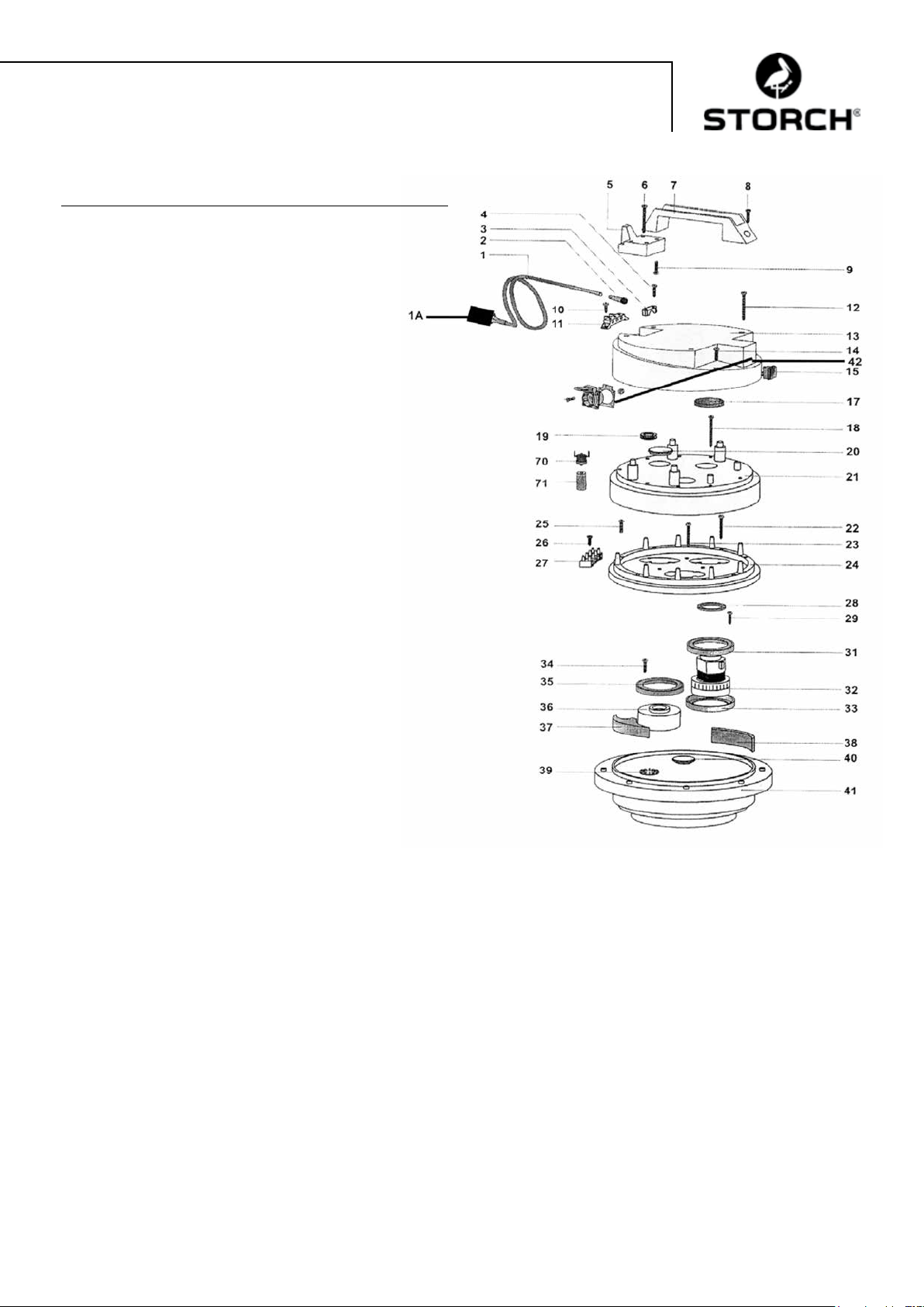
Testa aspiratrice:
Pos. Descrizione N. art.
1 Cavo di corrente 2 x 1,5, con spina 65 80 31
1a Spina di protezione personale IP 44 60 02 46
2 Condotto cavi per testa aspiratrice 65 80 33
3 Morsetto per cavi per testa aspiratrice 65 80 34
4 Vite a croce M 5 x 20 65 80 35
5 Supporto cavi per testa aspiratrice
HDK 85 65 80 36
6 Vite 5,2 x 50 65 80 37
7 Impugnatura per testa aspiratrice
HDK 85 65 80 38
8 Vite a croce M 5 x 35 65 80 39
9 Vite a croce M 5 x 20 65 80 35
10 Vite a croce M 5 x 14 65 80 41
11 Morsetto di collegamento 65 80 42
12 Vite 5,2 x 50 65 80 37
13 Coperchio della scatola per testa
aspiratrice 65 80 43
14 Vite a croce M 5 x 20 65 80 35
15 Interruttore ON/OFF per testa
aspiratrice 65 80 44
17 Filtro per testa aspiratrice HDK 85 65 80 45
18 Vite 5,2 x 50 65 80 37
19 Anello di protezione cavo 65 80 47
20 Tappo cieco 65 80 48
21 Coperchio motore per testa aspiratrice 65 80 49
22 Vite autolettante 3 x 40 65 80 51
23 Vite autolettante 3 x 40 65 80 51
24 Anello di attacco per testa aspiratrice 65 80 52
25 Vite a croce M 5 x 30 65 80 53
26 Vite autolettante 4,3 x 19 65 80 54
27 Morsetto a 4 contatti 65 80 55
28 Anello di tenuta 65 80 56
29 Vite a croce M 5 x 20 65 80 35
31 Guarnizione motore per testa aspiratrice 65 80 57
32 Motore per HDK 85 65 80 03
33 Guarnizione motore per testa aspiratrice 65 80 57
34 Vite a croce M 5 x 20 65 80 35
35 Guarnizione motore per testa aspiratrice 65 80 57
36 Distanziatore 65 80 61
37 Elemento di guarnizione per testa
aspirante 65 80 62
38 Filtro 65 x 10, L = 120 65 80 63
39 Disco di accoppiamento 65 80 64
40 Cappuccio 65 80 65
41 Piastra di fermo motore 65 80 66
42 Presa Schuko per testa aspiratrice 65 80 67
70 Interruttore termico per HDK 85 65 80 07
71 Supporto per contatto termico 65 80 68
45
Page 46
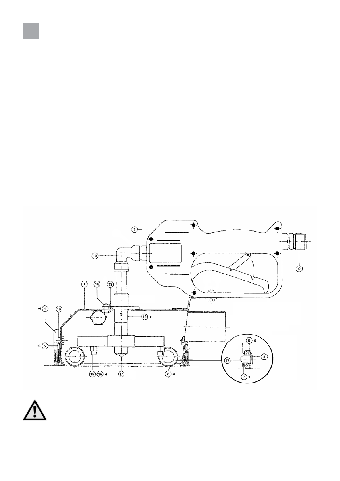
Calotta detergente standard - Pezzi di ricambio:
Pos. Descrizione N. art.
1 Calotta 65 74 01
3 Valvola di blocco HD (nuova) 65 71 30
4 Set spazzole di tenuto, 4 pezzi 65 74 18
6 Rullo 65 74 04
7 Bronzina 65 74 05
8 Perno di banco 65 74 06
9 Nipplo di collegamento 65 71 21
10 Angolo 90 gradi 65 71 23
12 Componente intercambiabile per
getto a punto 65 75 51
12a Componente intercambiabile per
getto piano 65 75 52
15 Ugello 0,95 65 74 08
16 Ugello 1,27 65 74 19
17 Vite a testa bombata M 4 x 8 65 74 12
18 Vite a testa bombata M 5 x 10 65 74 13
senza immagine:
Rotelle larghe in Teon 65 75 54
Termometro con anello collante 65 75 53
* Pezzi soggetti all'usura
ATTENZIONE
Si consiglia l'utilizzo degli ugelli forniti a corredo con uno spessore di 1,27 mm, se l'idropulitrice ad alta pres-
sione impiegata vanta una capacità di oltre 11 l al minuto.
46
Page 47

Accessori e pezzi di ricambio:
Descrizione N. art.
Idropulitrice ad alta pressione professionale
135 bar 65 60 00
Idropulitrice ad alta pressione 220 bar,
benzina 65 60 50
completo di prolunga per essibile di
aspirazione di 10 m 65 70 10
Prolunga per essibile ad alta pressione,
10 m, per pressioni no a 400 bar, per
temperature max. di 150° C 65 65 14
Prolunga per essibile ad alta pressione,
10 m, compr. doppio nipplo di raccordo, per
pressioni no a 210 bar, per temperature
max. di 150° C 65 65 30
Raccordi a doppio essibile per alta
pressione M 22 x 1,5 65 65 31
Prolunga per essibile di scarico 10 m 65 70 16
Sostegno per essibile 64 24 25
Calotte per superci di piccole dimensioni
6 x 6 cm 65 76 50
Calotte per superci di grandi dimensioni
44 x 40 cm 65 75 60
Dispositivo per la pulitura di pavimenti per
calotta per superci grandi 65 75 80
Ugelli per l'aspirazione dell'acqua 65 10 30
Tubo di aspirazione in metallo di 1,2 m 65 10 10
Descrizione N. art.
Aspiratore pezzi di ricambio:
Sacchetto ltro riutilizzabile in tessuto 210 mµ 65 77 30
Sacchetto ltro riutilizzabile in tessuto 300 mµ 65 77 31
Sacchetto ltro riutilizzabile in tessuto 400 mµ 65 77 32
Giunzione per essibile di aspirazione 65 70 11
47
Page 48

Garanzia
Condizioni di garanzia
Per i nostri apparecchi sono applicabili dei periodi di garanzia di 12 mesi a partire dalla data di acquisto / data della
fattura del cliente finale commerciale. Se da parte nostra vengono accordati dei periodi di garanzia più estesi, ciò sarà
riportato separatamente nelle istruzioni per l'uso inerenti ai rispettivi dispositivi.
Rivendicazioni
In casi in cui si intende far valere il diritto di garanzia, vi preghiamo di inviarci il dispositivo in modo completo con fattura, franco nostro centro di logistica a Berka oppure ad una service-station da noi autorizzata.
Si prega di consultare prima la Hotline di servizio STORCH a pagamento: 02 - 66227715
Diritto alla garanzia
Il diritti si possono far valere solo per errori di materiale o di produzione nonché esclusivamente in caso di utilizzo
appropriato del dispositivo. Componenti soggetti a logorio, come spazzole di tenuta, rulli, filtro dell'aria, guarnizioni,
fresa rotante, filtro riutilizzabile etc. non vengono contemplate da tale diritto. Scadranno tutti i diritti in caso di montaggio di parti di terzi, in caso di maneggio e magazzinaggio improprio come anche in caso di ovvia inosservanza delle
istruzioni per l'uso.
Esecuzione di riparazioni
Ogni intervento di riparazione va eseguito esclusivamente nei nostri stabilimenti o presso una service-station autorizzata STORCH.
48
Page 49
Dichiarazione di conformità CE
Nome / indirizzo dell'emittente: STORCH Malerwerkzeuge & Profigeräte GmbH
Platz der Republik 6 - 8
D - 42107 Wuppertal
ai sensi della Direttiva macchine CE 2006/42/CE allegato II A
Con la presente, noi dichiariamo che la macchina di seguito specificata
Denominazione della macchina: Detersore ad alta pressione 85
Tipo di macchina: Aspiratore a umido
Numero articolo: 65 80 00
corrisponde alle disposizioni pertinenti delle seguenti normative:
Direttiva macchine: 2006 / 42 / CE
Direttiva sulla compatibilità
elettromagnetica: 2004 / 108 / CE
Procuratore per la composizione della documentazione tecnica:
STORCH Malerwerkzeuge & Profigeräte GmbH
Platz der Republik 6 - 8
D-42107 Wuppertal
Holger Joest Jörg Heinemann
- Dirigente di prodotto Tecnologia + Servizio - - Direttore -
Wuppertal, aprile 2012
49
Page 50

GB
Thank you
for purchasing a STORCH product. You have purchased a quality product.
If you would like to suggest an improvement, or experience a problem with your product, please do not hesitate to
contact us.
Please contact your field sales representative or, in urgent cases, contact us directly.
Yours sincerely,
STORCH Service Department
Tel.: +49 (0)2 02 . 49 20 - 112
Fax: +49 (0)2 02 . 49 20 - 244
Free service hotline: 0800 786 72 47
Toll-free order hotline: +49 800 7867244
Toll-free order fax: +49 800 7867243
(only available in Germany)
Table of contents Page
Technical specifications 50 - 51
Scope of delivery 51
Functional description 51
Kite marks / Waste water regulations 51
Commissioning 52
Water pressure / Temperature 52
Cleaning attachment 52
Suction hose 53
Suction unit with immersion pump 53
Important notes 53
Safety precautions 54
Maintenance / Cleaning 54
Troubleshooting 55
Detailed drawings 56 - 58
Accessories and spares 59
Warranty conditions 60
Declaration of Conformity 61
Technical specications for suction unit:
− Voltage, alternating current: 230 V, 50 Hz
− Current consumption of 1 motor: 5.5 A
− Current consumption of 2 motors: 11 A
− Main fuse: 16 A
− Suction motor output: 2 x 1,220 watts
− Airow: max. 5,800 l/min
− Length of suction hose: max. 30 metres
− Length of connecting cable: max. 30 m, 2.5 mm², completely unwound
− Dimensions: L 780 mm x W 525 mm x H 1,310 mm
− Weight: 45 kg
− Noise level: 77 db (A)
Technical specications for immersion pump:
− Alternating current: 230 V, 50 Hz
− Current consumption: 1.4 A
− Power consumption: 320 W
− Motor speed: 2,800 rpm
− Delivery height: 1 / 3 / 5 / 7 m.
− Volume: 11 / 9 / 6 / 1 cubic metres / hr.
50
Page 51
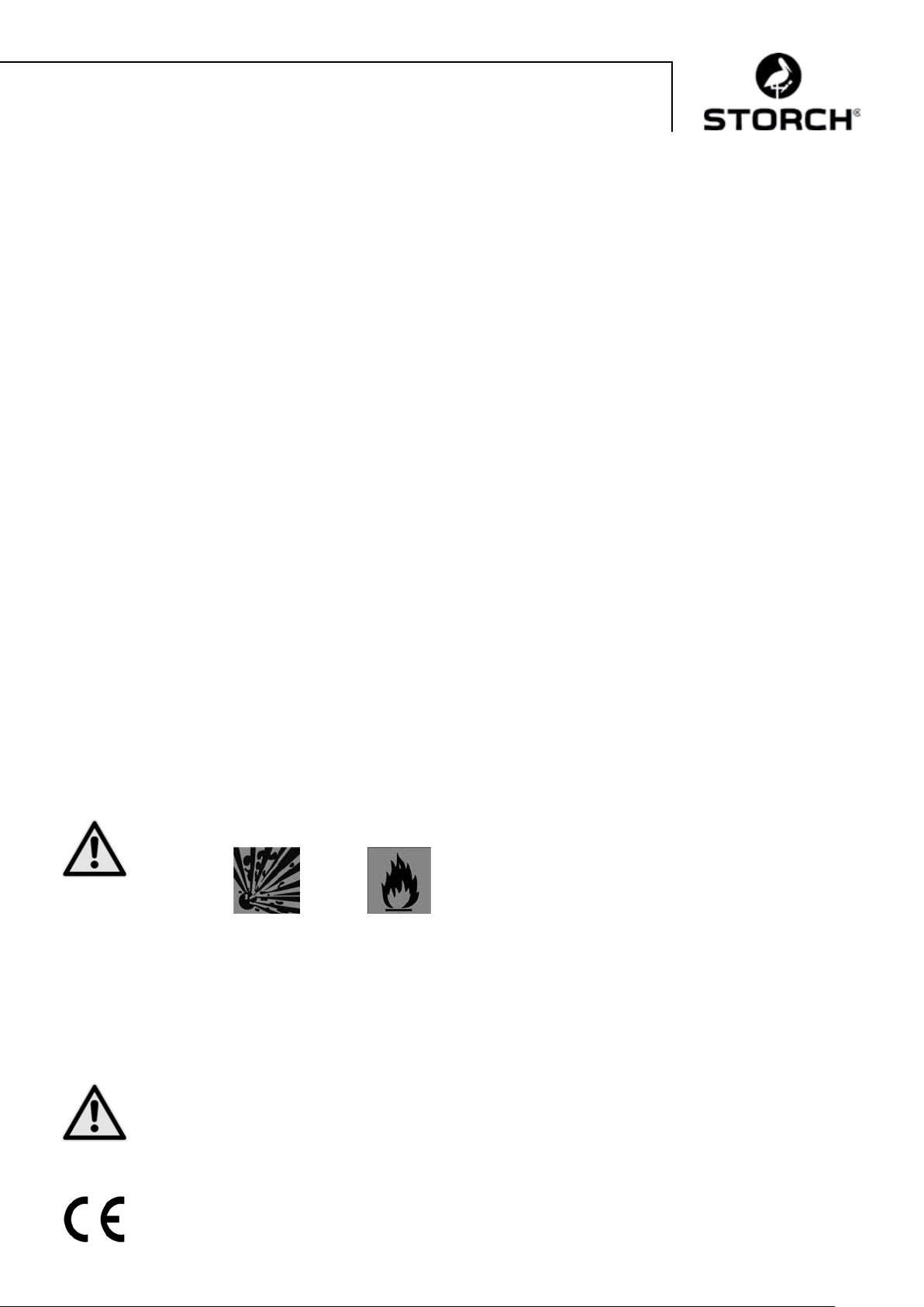
Technical specications for standard cleaning attachment:
− Overall width 150 mm, Overall length 340 mm, Working width approx. 110 mm
− Working pressure 60-200 bar.
− Water infeed max. 20 l/min.
− Water temperature max. 85° C
Scope of delivery of your STORCH High Pressure System Krake 85:
Standard cleaning attachment complete with sealing brushes
High pressure hose 10 m
Suction hose 10m
Discharge hose 10 m
Suction unit complete with lter, immersion pump and trolley
Connecting lead with ground fault circuit interrupter protected plug
Instruction manual
SAFETY CHECKS:
ENSURE COMPLIANCE WITH APPLICABLE NATIONAL LEGISLATION.
General functional description:
The STORCH High Pressure System Krake captures the water blasted onto a facade (or any other surface, walls, ceil-
ings, oors) by a high pressure cleaner: the solid particles contained in the waste water are ltered out as of a particle
diameter of 0.21 mm so that the treated water can typically (depending on the local waste water authority's regulations) be discharged into a waste water channel in an environmentally friendly way. The high pressure hose provided
with the machine is attached to the high pressure cleaner and the cleaning attachment which blasts the water via an
internal rotation nozzle onto the surface to be cleaned. The suction unit creates a vacuum in the cleaning attachment so
that the water is extracted directly into the suction unit through the suction hose without any notable volume of water
escaping from the cleaning attachment.
This makes it possible to use the high pressure cleaner for interior work (e.g. stairwells / churches) without any additional preparation. The suction unit can be used with one or two motors depending on the required extraction perform-
ance. To allow this to happen, the motors are switched separately at the main switch. The waste water is ltered in
the suction unit using a lter (210 - 400 mµ available) and then continually discharged via the discharge hose by the
integrated immersion pump.
CAUTION
Use of the High Pressure System Krake 85 is prohibited if materials with the following hazard symbols are
processed:
Explosive Extremely / highly ammable
The high-pressure Krake 85's motors are not protected against explosion and may ignite materials marked as such.
Please always refer to the material manufacturer's MSDS. Never use materials with a ash point below 21°C.
CAUTION
The diameter of the discharge hose should not be below ¾". The machine is supplied with a 400 my reusa-
ble filter.
Kite marks/Waste water regulations
IP 44
51
Page 52
CAUTION
Before discharging waste water into waste water channels, you must obtain a permit from the local water authority.
If you intend to discharge the waste water into a waste water channel, only use biodegradable strippers that comply
with water hazard class I, as dissolved strippers cannot be filtered. In all other cases, you may need to collect the
waste water in tanks and dispose of the waste water in line with your local water authority's regulations.
You cannot use the "Radikalfresser" stripper by Sikkens with this machine.
Commissioning the STORCH High Pressure System Krake:
The high pressure cleaner and suction unit must be connected to separate power supplies as the suction unit requires a
current of approx. 11 A, and - depending on the pressure cleaner you use - a single 16 A power supply could be overloaded. Place the upper suction basket and the upper container ring on the lower barrel and always connect the two using
the 3 tension locks! Using the high pressure hose, connect the high pressure cleaner to the cleaning attachment. Using
the suction hose connect the cleaning attachment and the suction unit. Plug the immersion pump plug (on the outside
of the barrel) into the socket provided on the suction basket. Check whether the suction unit, pump and discharge hose
are ready for operations. To do so, switch on the suction unit and the high pressure cleaner (switch the two motors on
the High Pressure System Krake on one after another - not at the same time, and then switch on the high pressure
cleaner) and place the cleaning attachment on the surface you wish to clean. Actuate the pistol grip on the cleaning
attachment and check whether the rotating nozzle is turning.
Water pressure and temperature
The cleaning attachment should be charged up to max. 200 bar. In order to prevent damage, select a water pressure on
the high-pressure cleaner that is suitable for the substrate. When working on soft substrates (e.g. plaster used for indoor
applications) use the wide plastic wheels (supplied) and the rotating nozzle with at jet (accessory). You can use a Hot
Box (art. no. 65 03 00) to improve working speeds by up to 40%, and considerably improve the cleaning performance,
due to the use of hot water.
CAUTION
The max. preset water temperature should not exceed 85 °C. A temperature monitor switches off the suc-
tion unit and the integrated immersion pump in the event of excessive temperature. Allow the system to
cool down for approx. 15 minutes and then switch the suction unit and immersion pump back on. For more
effective cooling, please open the suction unit by removing the suction basket from the lower barrel.
Cleaning attachment:
CAUTION
Never look or reach into the attachment! Risk of injury! The handle can either be attached to the left or right-
hand side by screwing it in place. The height of the sealing brushes can be adjusted by loosening the outer
screws. When working on smooth substrates the sealing brushes should be retracted as far as possible.
When working on rough substrates the sealing brushes should be extended in accordance with the depres-
sions in the substrate. Adjust the sealing brushes in such a way that no water escapes from the cleaning
attachment and that a light, fluid movement of the attachment is possible over the substrate. The cleaning
attachment is manipulated in vertical runs. The attachment can also be moved slightly to the side.
Make sure that the inside of the cleaning attachment is free of soiling that could prevent the rotating nozzles from turning.
Before starting work, check that water is exiting both nozzles on the rotating head, and that the water pressure is turning
the head in the cleaning attachment (never switch on the high pressure cleaner to do this).
CAUTION
Never look into the cleaning attachment from the side and never look directly into the rotating nozzle while
actuating the hand valve! If water is not ejected smoothly from the nozzles, it may mean they need cleaning.
In order to do this, use an 8 mm flat spanner to remove the two nozzles from the supporting arms, and care-
fully clean the inner bores. Actuate the hand valve again to flush out any particles that have been clogging
the supporting frame. Then reattach the nozzles and use the spanner to tighten the connections.
Remove any soiling that has built up on the roller bearings if the roller bearings do not turn easily.
52
Page 53
Note:
Regular cleaning, maintenance and servicing after completing work will help avoid downtime!
Suction hose:
The max. suction hose length must not exceed 30 m. Do not use a longer hose than necessary. Make sure that the hose
is always laid out straight without "sag" or kinks.
When you have nished using the machine ush the hose thoroughly to prevent clogging. When working on scaffolding,
we recommend you hang the hose on the scaffolding with hose clamps (art. no. 64 24 25) for strain relief.
Suction unit with immersion pump:
The suction basket is equipped with a vacuum ow interrupter which interrupts the ow if an excessive amount of soiling
has built up in the lter basket, preventing water exiting the lter basket so that the water level in the lter basket has
reached the max. level.
CAUTION
Stop work immediately: switch off the machine and clean the filter basket.
To empty the lter, release the 3 tension locks on the barrel and place the top section on the ground next to
the barrel. You can now pull out the supporting cage. Clean the reusable lter, ush the lter, and reassemble
in reverse order. When replacing the supporting cage, make sure the sealing ring is clean and seals properly!
If the lter basket lls up after a short time, it is a good idea to brush the surface you are cleaning rst, and
in case of stripping work to use a scraper to scrape off the aky coating rst and / to use a coarser replacable
lter. Besides the standard 400 mµ replacable lter, we also offer replacable lters with coarser meshing.
To empty residual water from the barrel, you can tip the machine. Before doing so, apply the brakes on the two front
castors on the trolley to prevent the trolley rolling away.
The immersion pump is switched on and off automatically by a oater switch.
There is no need to check the ll level, or to interrupt your to empty the tank. However, you must plug the pump into the
socket on the suction basket to provide power to the pump. On initial commissioning, or after a longer period of disuse
(weeks/months), a bubble of air may form in the immersion pump preventing water owing into the pump chamber. In
this case, make sure the pump is fully immersed in water. Plug the mains plug on your STORCH High Pressure System
Krake into an earthed socket and plug the pump on the pump into the socket on the suction basket. The pump will start
running. Now press the oater switch down with your hand (the pump will switch off); hold the oater down for a short
time and then release it (the pump will switch back on). Repeat this until the pump starts to deliver water.
CAUTION
Important notes:
− The STORCH High Pressure System Krake is designed only for wet vacuuming and not for use with dry,
dusty materials.
− The maximum water temperature must not exceed 85°C.
− Before starting work, always check if the immersion pump plug is plugged into the socket on the suction
basket.
− The tension locks on the barrel must be tightly closed.
− Always remove any clogging in the suction hose immediately. You will notice clogging by the fact that the
motor speed increases notably, while the vacuum performance drops. You must switch off the machine
immediately. When you nish work, always completely drain and ush the suction hose.
− Check the air lter regularly for signs of wear and tear, soiling and damage. A damage lter impacts per-
formance and can endanger the safety of your machine.
− Regularly check the vacuum ow interrupter to make sure that it is clean and moving freely; check for
signs of damage to the ball and seal (ball seating).
− Replace worn and damaged parts.
If you observe these important notes, you will have a reliable tool at hand. If you fail to observe these points, your warranty will be voided in case of damage.
53
Page 54
Safety instructions:
When working with the cleaning attachment never allow the pressurized nozzles or the water jet to touch
your hands or any other part of your body. The manual lever on the high pressure shut off valve in the clean-
ing attachment must not be jammed in open position. When you interrupt or finish work, secure the manual
lever on the high pressure shut off valve against accidental triggering (engage the safety lock). Never point
the cleaning attachment at persons; note that the residual pressure after switching off the high pressure
cleaner could be sufficient to cause injury. Never reach into the immediate vicinity of the high pressure jet;
keep a distance of at least 30 cm. If you are not using the machine (e.g. during breaks), switch off the High
Pressure System Krake and the high pressure cleaner and release the pressure on the cleaning attachment
by removing the manual valve.
CAUTION
Only clean or remove the rotating nozzle inside the cleaning attachment when you have detached the high
pressure hose from the cleaning attachment. Danger of injury!
CAUTION Heat:
When working with hot water, you must wear suitable personal protection (e.g. gloves, goggles, protective
headgear for overhead work). Never clean the machine immediately after nishing work. Remove the suction
basket and allow the machine to cool down for approx. 15 minutes. When working with hot water on scaffolding
make sure that no persons are on the lower levels of the scaffolding to prevent danger of scalding.
CAUTION
The machine should not be used:
− in areas where there is a risk of explosion and/or to vacuum potentially explosive substances.
− This applies in particular to areas in which machines must be B1 compliant;
− to vacuum dusts that are hazardous to health;
− to vacuum ammable liquids and acids;
− to vacuum oily or non-conductive liquids;
− to vacuum ignition sources;
− without a lter for vacuum cleaning.
CAUTION Electrics:
Never run over, crush or strain the power lead. Check the power lead on the immersion pump and suction
unit regularly for signs of damage. If you detect any damage, do not use the machine. When replacing power
or machine connecting leads, observe the manufacturer's specifications. Couplings on any extension leads
you use must be waterproof. Avoid damaging the pump leads when cleaning the inside of the barrel. Unplug
the mains plug before commencing maintenance work. When cleaning and maintaining machines, replacing
parts, or retooling for a different task, switch the mains switch to the "0" position and unplug the mains
plug. The machine must be operated by trained staff only who are familiar with safety instructions and have
been explicitly instructed to use the machine. Observe the safety and accident prevent rules that apply on
site when using the machine.
The device possesses a voltage range which can pose an electrical hazard to humans and animals. It should only be unscrewed and / or disassembled by authorised personnel. Similarly, maintenance and repair work should only be conducted
by electrical specialists and authorised service centres. The buyer / user operates the device at their own risk and under
their own responsibility.
Maintenance / Cleaning:
After use, tip the remaining waste water out of the suction unit barrel. Always ush the barrel with clean water. Remove
stones, paint residue and soiling from the suction inlet on the immersion pump. After cleaning do not connect the barrel
to the suction basket, but allow both parts to dry.
When cleaning, check the machine air lter cartridge below the suction basket for signs of soiling and damage. To ensure
optimum vacuum ow interruption when the lter basket is full, keep the ball in the lter basket, the lter basket itself
and the seal clean.
Flush the cleaning unit thoroughly with clean water after use. Make sure you clean the sealing brushes thoroughly. Re-
move the rollers from time to time to remove soiling from the roller berakings. To do so, loosen the screws at the sides
(remove the sealing brushes rst).
54
Page 55

Troubleshooting:
Cleaning performance with the cleaning attachment is insufficient:
• The rotation nozzle is not turning
• Scaly deposits on the rotor
• Blocked by particles of dirt
• Turn multiple time manually (make sure the high pressure cleaner is depressurized before doing so)
• Disassemble and clean
• In case of excessive and sudden water pressure, the cleaning head can freeze. In this case, press the high pressure
cut off trigger multiple times.
• Is the high pressure cleaner producing sufcient pressure?
• Is there a sufcient supply of water to the high pressure cleaner? (Inlet line must be ¾")
• The rotating nozzle may be worn and need replacing.
• No water is being discharged from the suction unit:
• Air pocket in the pump
• Is the power lead for the immersion pump plugged in at the suction basket?
• The immersion pump is standing in mud and can't extract water
• Discharge hose kinked.
• No vacuum or insufcient vacuum:
• Vacuum ow interrupted due to excessive solid build up in lter basket
• Machine switched off by thermocouple (caused by vacuum ow interruption / blocked, kinked, or sagging suction
hose / excessive water temperature)
• Is the top section with motor positioned precisely on the lower barrel?
• Check the sealing ring on the lter basket between the barrel parts for signs of damage and soiling
• Check the suction hose coupling
• Only one suction motor switched on
• Rollers on the cleaning attachment not turning:
• Remove soiling between bearings and rollers.
• Water escaping from the attachment:
• Clean sealing brushes to remove clogging, or replace brushes.
• Insufcient vacuum build up
• Incorrect height setting of sealing brushes
• Vacuum ow interruption triggered (clean lter basket)
• Unable to actuate cleaning attachment trigger:
• Release the lock
• Vacuum switching off:
• Machine switched off by thermocouple (caused by vacuum ow interruption
• blocked, kinked, or sagging suction hose / excessive water temperature)
• Check power supply: the circuit breaker may have triggered. Use only 2.5mm² diameter
• extension lead. Total length must not exceed 30 metes. Completely unwind extension reels.
• Bellow air lter below suction unit wet and / or soiled
• Check if the pump plug is plugged into the suction unit (otherwise the water level will rise and the vacuum ow
interrupter will trigger).
• Switch motors on individually.
• Attach all machines to different power supplies.
• Check the 230V power supply.
• Set both main switches to "0" position. Remove the cause of the malfunction and switch the machine back on after
waiting for approx. 5 min.
55
Page 56
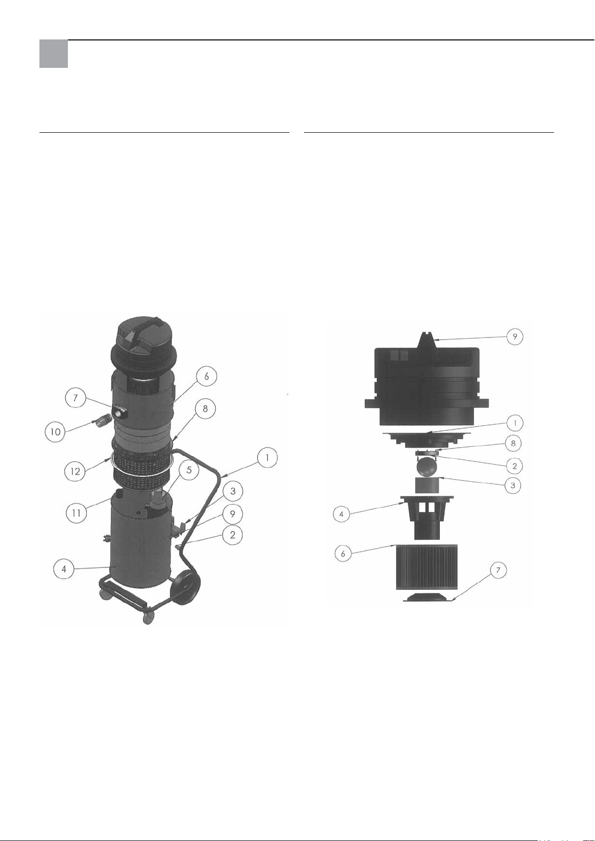
High Pressure System Krake 85 complete:
Suction head:
Pos. Designation Art. no.
1 Wheel assembly, complete 65 80 11
2 Spacer for suction unit 65 80 16
3 Tilting mechanism 65 77 47
4 Lower barrel complete (without pump) 65 80 08
5 Immersion pump 65 77 17
6 Barrel top section complete 65 80 09
7 Barrel coupling complete,
including inlet socket 65 80 13
8 Filter supporting cage 65 80 12
9 Cable gland complete Krake 85 65 80 17
11 Coupler with non-return valve 65 80 14
12 Seal for supporting cage 65 77 20
Pos. Designation Art. no.
1 Motor mounting plate 65 80 66
2 Seal for cut-off ball 65 80 19
3 Filter screen 65 80 73
4 Float chamber 65 80 72
5 Cut-off ball 65 80 21
6 Folded lter C 65 77 25
7 Retainer for lter cartridge 65 80 75
8 Chipboard screw 3 x 20 65 80 22
9 Suction head 2,400 W, blue, complete 65 80 20
56
Page 57
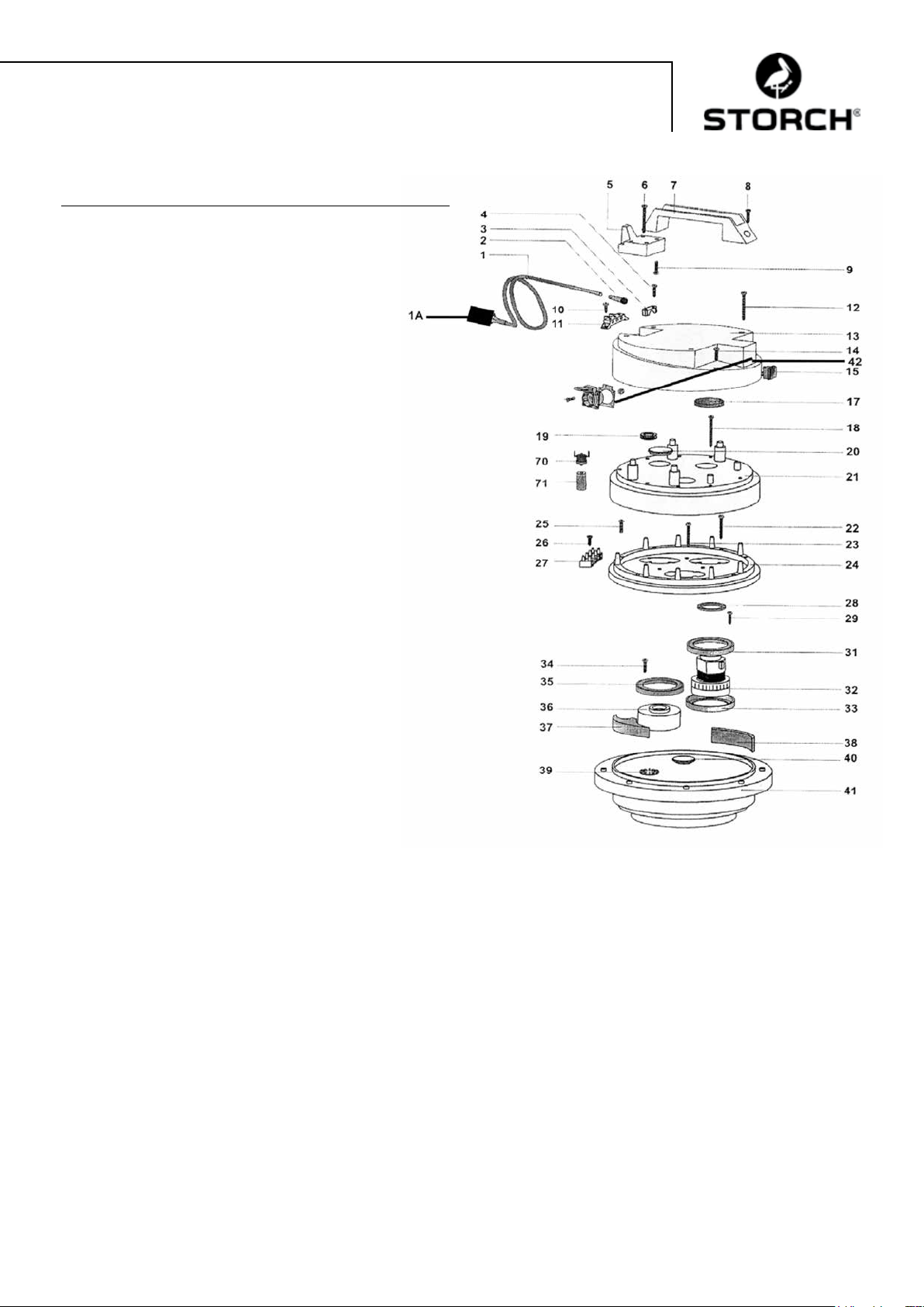
Suction head:
Pos. Designation Art. no.
1 Power cable 2 x 1.5, with plug 65 80 31
1a Personal protection plug IP 44 60 02 46
2 Cable guide for suction head 65 80 33
3 Cable clamp for suction head 65 80 34
4 Phillips screw M 5 x 20 65 80 35
5 Cable holder for suction head HDK 85 65 80 36
6 Screw 5.2 x 50 65 80 37
7 Handle for suction head HDK 85 65 80 38
8 Phillips screw M 5 x 35 65 80 39
9 Phillips screw M 5 x 20 65 80 35
10 Phillips screw M 5 x 14, 65 80 41
11 Connecting terminal 65 80 42
12 Screw 5.2 x 50 65 80 37
13 Housing cover for suction head 65 80 43
14 Phillips screw M 5 x 20 65 80 35
15 On / Off switch for suction head 65 80 44
17 Filter for suction head HDK 85 65 80 45
18 Screw 5.2 x 50 65 80 37
19 Cable protector 65 80 47
20 Blanking plug 65 80 48
21 Motor cover for suction head 65 80 49
22 Tapping screw 3 x 40 65 80 51
23 Tapping screw 3 x 40 65 80 51
24 Seating ring for suction head 65 80 52
25 Phillips screw M 5 x 30 65 80 53
26 Tapping screw 4.3 x 19 65 80 54
27 Connecting terminal, 4-pin 65 80 55
28 Sealing ring 65 80 56
29 Phillips screw M 5 x 20 65 80 35
31 Motor seal for suction head 65 80 57
32 Motor for HDK 85 65 80 03
33 Motor seal for suction head 65 80 57
34 Phillips screw M 5 x 20 65 80 35
35 Motor seal for suction head 65 80 57
36 Spacer 65 80 61
37 Sealing piece for suction head 65 80 62
38 Filter 65 x 10, L = 120 65 80 63
39 Coupling disc 65 80 64
40 Cover cap 65 80 65
41 Motor mounting plate 65 80 66
42 Safety socket for suction head 65 80 67
70 Thermo switch for HDK 85 65 80 07
71 Retainer for thermal contact 65 80 68
57
Page 58
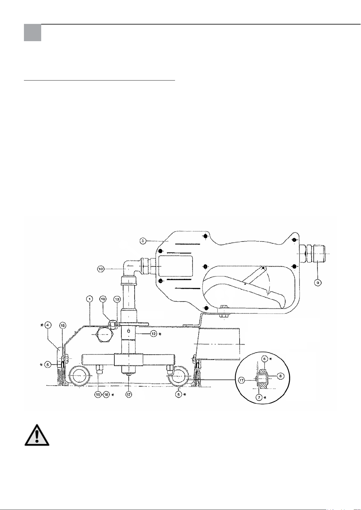
Standard cleaning attachment spares:
Pos. Designation Art. no.
1 Hood 65 74 01
3 HP shut-off valve (new) 65 71 30
4 Sealing brush set, 4-piece 65 74 18
6 Roller 65 74 04
7 Bearings 65 74 05
8 Bearing journal 65 74 06
9 Connection nipple 65 71 21
10 Bracket 90 degree 65 71 23
12 Interchange part jet stream, at stream 65 75 51
12a Interchange part at stream 65 75 52
15 Nozzle 0.95 65 74 08
16 Nozzle 1.27 (with groove) 65 74 19
17 Fillister head screw M4x8 65 74 12
18 Fillister head screw M5x10 65 74 13
Not illustrated:
Teon rollers, wide 65 75 54
Thermometer with adhesive washer 65 75 53
* Wear parts
CAUTION
We recommend the use of the nozzles as provided with a diameter of 1.27 mm, if the high pressure cleaner
you use delivers more than 11 l water per minute.
58
Page 59

Designation Art. no.
Professional pressure cleaner 135 bar 65 60 00
Professional pressure cleaner 220 bar,
petrol driven 65 60 50
Extension suction hose cpl., 10m 65 70 10
Extension HP hose, 10 m, pressure load up
to 400 bar, max. temperature load 150° C 65 65 14
Extension HP hose, 10 m, incl. double
connection nipple, pressure load up to 210 bar,
max. temperature load 150° C 65 65 30
Double nipple connections high pressure hose
M 22 x 1.5 65 65 31
Discharge hose extension 10 m 65 70 16
Hose clamps 64 24 25
Cleaning attachment for
small surfaces 6 x 6 cm 65 76 50
Cleaning attachment for
large surfaces 44 x 40 cm 65 75 60
Floor cleaning adapter for large surface
cleaning attachment 65 75 80
Water intake nozzle for water intake 65 10 30
Metal intake tube 1.2 m 65 10 10
Designation Art. no.
Spare parts for suction unit:
Reusuable mesh lter bag 210 mµ 65 77 30
Reusuable mesh lter bag 300 mµ 65 77 31
Reusuable mesh lter bag 400 mµ 65 77 32
Coupling for suction hose 65 70 11
59
Page 60

Warranty
Warranty conditions
A warranty period of 12 months from the date of purchase/date of invoice applies to our tools for commercial customers. If we have granted an extended warranty period, this period will be noted separately in the operating manual for
the equipment in question.
Claims
If you wish to claim under our warranty or guarantee, please return the complete device and your invoice to our logistics
centre in Berka, postage paid, or send it to one of our authorised service centres.
Please contact the chargeable STORCH service hotline first: +49 (0)202 . 49 20 – 110.
Your rights under our warranty or guarantee
Claims for repairs only relate to materials or manufacturing defects and are subject to the intended use of the tool.
Wear and tear parts such as sealing brushes, rollers, air filters, seals, rotating nozzles, reusuable filters etc. are not
covered by warranty or guarantee. All claims shall become void in the event of installation of third party components,
improper handling and storage, as well as in the event of obvious disregard of the operating instructions.
Repairs
All repairs have to be conducted on our premises or by an authorised STORCH service centre.
60
Page 61
EG Declaration of Conformity
Name / Address of issuer: STORCH Malerwerkzeuge & Profigeräte GmbH
Platz der Republik 6-8
D - 42107 Wuppertal
according to EC Machinery Directive 2006/42 EC Appendix II A
We hereby declare that the following machine
Description of the machine: High Pressure System Krake 85
Machine type: Wet suction unit
Article number: 65 80 00
complies with the relevant provisions of the following directives:
Machinery Directive: 2006 / 42 / EC
EMC Directive: 2004 / 108 / EC
Authorised agent for compilation of the technical documents:
STORCH Malerwerkzeuge & Profigeräte GmbH
Platz der Republik 6-8
D-42107 Wuppertal, Germany
Holger Joest Jörg Heinemann
- Director of Product Management Technology & Service - - Managing Director -
Wuppertal, April 2012
61
Page 62

CZ
Děkujeme Vám
za důvěru ve firmu STORCH. S nákupem výrobku jste se rozhodli pro kvalitní produkt.
Pokud přesto máte podněty na zlepšení nebo možná nějaký problém, tak bychom byli velmi rádi, kdybyste se nám
ozvali.
Promluvte si s příslušným externím spolupracovníkem naší firmy nebo se v naléhavých případech obracejte přímo na
nás.
S přátelským pozdravem
Servisní oddělení STORCH
Tel.: +49 (0)2 02 . 49 20 - 112
Fax: +49 (0)2 02 . 49 20 - 244
bezplatná linka Hotline-servis: 08 00. 7 86 72 47
bezplatná linka Hotline-objednávky: +49 800. 7 86 72 44
bezplatný fax-objednávky: +49 800. 7 86 72 43
(pouze v Německu)
Obsah Strana
Technické údaje 62 - 63
Rozsah dodávky 63
Popis funkce 63
Kontrolní značka/ Ustanovení k odvádění vody 63
Uvedení do provozu 64
Tlak vody / Teplota 64
Čistící poklop 64
Sací hadice 65
Odsávací přístroj s ponorným čerpadlem 65
Důležité pokyny 65
Bezpečnostní pokyny 66
Údržba / čištění 66
Diagnostika chyb 67
Detailní výkresy 68 - 70
Příslušenství a náhradní díly 71
Záruční ustanovení 72
Prohlášení o shodě 73
Technické údaje sací agregát:
Napětí střídavý proud 230 V, 50Hz
Příkon proudu 1 motor 5,5 A
Příkon proudu 2 motory 11 A
Pojistka v el.síti 16 A
Výkon sacího motoru 2 x 1.220 watů
Množství protékajícího vzduchu max. 5 800 l/min
Délka sací hadice max. 30 metrů
Délka připojovacího kabelu max. 30 m, 2,5mm², kompletně odvinuté
Rozměry zařízení D 780 mm x Š 525 mm x V 1.310 mm
Hmotnost 45 kg
Hladina hluku 77 db (A)
Technické údaje ponorné čerpadlo:
Střídavý proud 230 V, 50Hz
Příkon proudu 1,4 A
Odebíratelný výkon 320 W
Počet otáček motoru 2.800 ot./min.
Dopravní výkon 1 / 3 / 5 / 7 m.
Objem 11 / 9 / 6 / 1 krychlových metrů/hod.
62
Page 63
Technické údaje Standardní čistící poklop:
Celková šířka 150 mm, celková délka 340 mm, pracovní šířka cca 110 mm
Pracovní tlak 60-200 barů.
Přívod vody max. 20 l/min.
Teplota vody max. 85° C
Rozsah dodávky Vysokotlakého čistícího zařízení Krake 85 od firmy STORCH:
Standardní-čistící poklop kompletně s těsnícími kartáčky
Vysokotlaká hadice 10 m
Sací hadice 10 m
Odtoková hadice 10 m
Odsávací přístroj kompletně s filtrem, ponorným čerpadlem a
pojízdným stojanem
Připojovací kabel s ochrannou zástrčkou FI
Návod k obsluze
BEZPEČNOSTNĚ-TECHNICKÉ ZKOUŠKY:
JE TŘEBA DODRŽOVAT PŘÍSLUŠNÉ NÁRODNÍ PŘEDPISY.
Všeobecný popis funkce:
S vysokotlakým čistícím zařízením Krake od firmy STORCH se bezprostředně zachytí voda, kterou je vysokotlakým
čistícím zařízením otryskávána fasáda (nebo jiné plochy, stěny, stropy, podlahy); pevné látky obsažené v odtékající
odpadní vodě se od průměru částic 0,21 mm odfiltrují, takže vyčištěnou vodu lze zpravidla (podle předpisů pro odpadní
vody místního úřadu) v souladu s ochranou životního prostředí odvést do splaškové stoky. Dodaná vysokotlaká hadice
se napojí na vysokotlaké čistící zařízení a na čistící poklop, přes který je voda vedena přes zabudovanou rotační trysku
k otryskávání čištěné plochy. Pomocí odsávacího přístroje se v čistícím poklopu vytvoří vakuum, takže je odpadní voda
odsávána sací hadicí přímo do odsávacího přístroje, aniž by mohlo z čistícího poklopu uniknout podstatné množství
vody.
Tímto způsobem lze vysokotlaké čistící zařízení dokonce bez jakýchkoli úprav používat ve vnitřních prostorách (např.
na schodištích / v kostelech). Odsávací přístroj lze podle požadovaného sacího výkonu používat s jedním nebo dvěma
motory. K tomu účelu lze motory odděleně zapoijit k hlavním spínačům. Znečištěná voda se v odsávacím přístroji odfiltruje filtrem (k dostání 210 - 400 mµ) a potom se zabudovaným ponorným čerpadlem průběžně odčerpává přes odtokovou hadici.
POZOR
Použití vysokotlakého zařízení Krake 85 je zakázáno, pokud byly zpracovávány materiály s následujícím
upozorněním na nebezpečí:
Explo- zivní Vysoce / snadno zápalné
Motory vysokotlakého zařízení Krake 85 nejsou chráněny proti explozi a mohou zapálit příslušně označené materiály.
Bezpodmínečně respektujte bezpečnostní listy výrobce materiálu. Nikdy nepoužívejte materiály s bodem vzplanutí
menším než 21° C.
POZOR
Průměr hadice u odtokové hadice nesmí být menší než ¾“. Zařízení se dodává s filtrem 400 my na více
použití.
Zkušební znak / úvodní ustanovení
IP44
63
Page 64
POZOR
Před odváděním odpadní vody do splaškové stoky je vždy třeba si obstarat povolení k odvádění vody u
příslušného místního vodárenského úřadu. Používejte pouze biologicky rozložitelné odstraňovače třídy
ohrožení vod I, pokud chcete odpadní vody odvádět do splaškové stoky, protože rozpuštěné odstraňovače
nelze odfiltrovat. Jinak musíte podle místních předpisů pro odpadní vody popřípadě odpadní vody sbírat do
nádrží a zlikvidovat je.
Odstraňovač „Radikalfresser“ firmy Sikkens nelze tímto přístrojem zpracovávat.
Zprovoznění vysokotlakého čistícího zařízení Krake od firmy STORCH:
Vysokotlaké čistící zařízení a odsávací přístroj musí být připojeny v oddělených elektrických proudových okruzích,
protože odsávací přístroj odebírá celkem cca 11 A el. proudu a jediný elektrický proudový okruh jištěný 16 A by byl
přetížen - podle použitého vysokotlakého čistícího zařízení. Postavte sací hlavu horním kruhem nádrže na spodní nádobu a spojte je vždy 3 stahovacími uzávěry! Spojte vysokotlaké čistící zařízení s čistícím poklopem pomocí vysokotlaké hadice. Spojte čistící poklop a odsávací přístroj sací hadicí. Zasuňte zástrčku ponorného čerpadla (vně na nádobě)
do k tomu určené zásuvky na sací hlavě. Zkontrolujte, zda je funkční odsávací přístroj včetně čerpadla a odtokové
hadice. Zapněte odsávací přístroj a vysokotlaké čistící zařízení (oba motory vysokotlakého zařízení Krake po sobě ne současně, potom vysokotlaké čistící zařízení) a nasaďte čistící poklop na plochu, která má být čištěna. Stiskněte
držadlo pistole na čistícím poklopu a zkontrolujte, zda se točí rotační tryska.
Tlak vody a teplota vody:
U čistícího poklopu smí být nastaveno ostřikování do max. 200 barů. Zvolte na vysokotlakém čistícím zařízení tlak
vody vhodný pro podklad, aby nedošlo k poškození opracovávaného podkladu. Pro měkké podklady (např. omítky ve
vnitřních prostorách) použijte široký plastový válec (v rozsahu dodávky) a rotační trysku s uspořádáním trysek na plocho
(příslušenství). Použitím Hot-Boxu (výr. č. 65 03 00) se horkou vodou zvýší účinnost pracovního postupu až o 40 % a
celkový výsledek čištění se podstatně zvýší.
POZOR
Nastavená teplota vody smí být max. 85 ° C. Teplotní čidlo vypne při překročení teploty sací přístroj a
zabudované ponorné čerpadlo. Po době ochlazování cca 15 minut lze sací přístroj a ponorné čerpadlo opět
zapnout. Aby se podpořila fáze ochlazování, otevřte prosím odsávací přístroj tím, že sací hlavu sejmete ze
spodní části nádoby.
Čistící poklop:
POZOR
Nedívejte se nebo nesahejte do čistícího poklopu! Nebezpečí úrazu! Držadlo lze našroubováním volitelně
umístit vpravo nebo vlevo. Těsnící kartáčky lze výškově nastavit po uvolnění vně umístěných šroubů. U
hladkých ploch by měly být těsnící kartáčky zasunuty až po zarážku. U drsného podkladu povyjednou těsnící
kartáčky dále podle prohlubní v podkladu. Nastavte těsnící kartáčky tak, aby z poklopu nevytékala žádná
voda a aby byl možný lehký a plynulý pohyb čistícího poklopu na podkladu. Čístící poklop se vede ve vertikálních pruzích. Poklopem lze pohybovat také mírně do stran.
Zajistěte, aby čistící poklop byl uvnitř bez znečištění, které by mohlo zamezit otáčení rotační trysky. Překontrolujte před
každým začátkem práce, zda rovnoměrně vytéká voda oběma tryskami rotační trysky a zda se rotační tryska otáčí v čistícím
poklopu tlakem vody z vodovodu (v žádném případě ne se zapnutým vysokotlakým čistícím zařízením).
POZOR
Nahlédněte při tom ze strany dovnitř do čistícího poklopu, nikdy se nedívejte přímo zepředu na rotační
trysku a stiskněte přitom ruční ventil! Pokud voda z trysek nevytéká rovnoměrně, je nutno je vyčistit:
Vyšroubujte obě trysky otevřeným klíčem SW 8 mm z ramen nosníku a pečlivě vyčistěte vnitřní vyvrtané
otvory. Stiskněte ještě jednou ruční ventil, aby se případné částečky nečistot vypláchly z ramen nosníku.
Poté trysky opět našroubujte a pevně dotáhněte otevřeným klíčem.
Odstraňte částečky nečistot, které se mohly usadit v ložiscích vodících koleček, pokud se jimi již nedá snadno otáčet.
64
Page 65
Upozornění:
Pravidelné čištění, péče a údržba po ukončení práce zabraňují poruchám!
Sací hadice:
Max. délka sací hadice nesmí předkročit 30 m. Nepoužívejte větší délky hadic než je třeba. Dbejte na to, aby sací hadice
byla vždy položená v rovných pruzích a nebyla „prověšená“ a / nebo zalomená.
Při ukončení práce hadici dostatečně propláchněte, aby se neucpala. Při práci na lešení doporučujeme kvůli odlehčení od
tahu zavěsit sací hadici na lešení do držáků (výr. č. 64 24 25).
Odsávací přístroj s ponorným čerpadlem:
Sací hlava je vybavena přerušením sacího proudu, které přeruší sací výkon, pokud je podíl pevných částic ve filtračním
koši příliš vysoký, voda z filtračního koše již nemůže odtékat a hladina vody ve filtračním koši dosáhla max. výšky.
POZOR
Práce je třeba okamžitě přerušit, přístroj vypnout a vyčistit filtrační koš.
K vyprázdnění filtru uvolněte 3 stahovací uzávěry na nádobě a nástavec z nádoby postavte vedle nádoby. Nyní
můžete opěrný koš pohodlně vytáhnout. Vyčistěte filtr na více použití, vyperte ho a přístroj sestavte opět
dohromady v obráceném pořadí. Při nasazování opěrného koše zpět dbejte na to, aby těsnící kroužek byl čistý
a hladce těsnil! Pokud se naplní filtrační koš již po krátké době, doporučuje se při čistících pracích okartáčovat
podklad a při pracích na odstraňování nátěru uvolněnou vrstvu odstranit širokou špachtlí a / nebo použít hrubší
filtrační koš na více použití. Kromě sériového filtru 400 mµ na více použití nabízíme také filtr na více použití
v hrubších šířkách stroje.
Aby se vyprázdnila zbývající voda z nádoby, lze ji naklopit. Zafixujte předtím přední otočné kolečko na stojanu, aby se
zabránilo neúmyslnému pojíždění stojanu.
Ponorné čerpadlo se automaticky vypíná a zapíná přes plovákový spínač.
Kontrola stavu naplnění odpadá a zabrání se přerušování práce vyprazdňováním nádoby. Čerpadlo však musí být napájeno
proudem přes zásuvku na sací hlavě. Při prvním použití nebo po delší době stání (týdny/měsíce), se může v ponorném
čerpadlu utvořit vzduchový polštář, takže do komory čerpadla neteče žádná voda. V tom případě zajistěte, aby čerpadlo
kompletně stálo ve vodě. Zasuňte síťovou zástrčku vysokotlakého čistícího zařízení Krake od firmy STORCH do uzemněné
zásuvky a spojte zástrčku čerpadla se sací hlavou. Čerpadlo se rozběhne. Nyní tiskněte rukou plovák směrem dolů (čerpadlo
se vypne), držte ho po krátkou dobu dole a opět ho pusťte (čerpadlo se opět zapne). Opakujte tento postup dokud nebude
voda odčerpána.
POZOR
Důležité pokyny:
Vysokotlaké čistící zařízení Krake od firmy STORCH smí být používáno pouze k sání na mokro a ne k sání
suchého, prašného materiálu.
Maximální teplota vody nesmí překročit 85°C.
Před začátkem prací prosím bezpodmínečně zkontrolujte, zda je zástrčka ponorného čerpadla zasunuta do
sací hlavy.
Stahovací uzávěry na nádrži musí být pevně uzavřené.
Ucpání sací hadice je třeba okamžitě odstranit. To se rozezná slyšitelně narůstajícím počtem otáček motorů
a slábnoucím sacím výkonem. Přístroj se musí okamžitě vypnout. Při ukončení práce se musí hadice úplně
vyprázdnit a propláchnout.
Pravidelná kontrola vzduchového filtru ohledně opotřebení, znečištění a poškození. Neintaktní filtr narušuje
výkon a bezpečnost přístroje.
Pravidlená kontrola přerušení sacího proudu ohledně čistoty a volnosti chodu a také ohledně poškození
kuliček a těsnění (uložení kuliček).
Výměna opotřebených a neintaktních dílů.
Při dodržování těchto důležitých pokynů budete mít vždy po ruce spolehlivý pracovní přístroj. Při zanedbání těchto bodů
zaniká při škodách tím vzniklých nárok na záruku.
65
Page 66
Bezpečnostní pokyny:
Při práci s čistícím poklopem se nesmějí ruce nebo jiné části těla dávat před trysky, které jsou pod tlakem,
nebo do proudu vody. Ruční páka vysokotlakého uzavíracího ventilu na čistícím poklopu nesmí být zafixována v poloze zapnuto. Při přerušení práce a při ukončení práce musí být ruční páka vysokotlakého uzavíracího
ventilu zajištěna proti neúmyslnému stisknutí (vyklapnout bezpečnostní západku). Čistící poklop nesměro-
vat na osoby, také od zbytkového tlaku po vypnutí vysokotlakého čistícího zařízení existuje nebezpečí úrazu
tlakem vody. Nesahat do bezprostřední blízkosti vysokotlakého proudu vody, vzdálenost min. 30 cm. Pokud není přístroj používán (pracovní přestávky), vypněte vysokotlaké zařízení Krake a vysokotlaké čistící zařízení a odlehčete tlak
na čistícím poklopu stáhnutím ručního ventilu.
POZOR
Rotační trysku uvnitř čistícího poklopu čistit příp. odstranit pouze tehdy, pokud je odmontována vysokotlaká
hadice od čistícího poklopu. Nebezpečí úrazu!
POZOR Horké:
Při práci s horkou vodou noste všeobecně vhodné ochranné vybavení (např. rukavice, ochranné brýle, pokrývku
hlavy při práci nad hlavou). Nečistěte přístroj bezprostředně po ukončení práce. Nechte sací přístroj při sejmuté
sací hlavě ještě cca 15 minut vychladnout. Při práci s horkou vodou na lešení dbejte na to, aby se na spodních
patrech lešení nenacházely žádné jiné osoby, aby se také zde vyloučilo nebezpečí opaření.
POZOR
Přístroj nesmí:
- Být používán na místech ohrožených explozí příp. odsávat látky ohrožené explozí.
To platí obzvláště pro oblasti, ve kterých se smějí používat pouze stroje, které jsou přezkoušeny dle B1.
- Být používán k odsávání prachu, který ohrožuje zdraví.
- Odsávat hořlavé kapaliny a kyseliny.
- Odsávat kapaliny obsahující olej nebo vodivé kapaliny.
- Odsávat zápalné zdroje.
- Být bez filtru používán k vysávání prachu.
POZOR Elektro:
Síťové přívodní vedení nesmí být přejižděno, přiskřípnuto nebo natahováno. Síťové přívodní vedení ponor-
ného čerpadla a sacího agregátu musí být pravidelně kontrolováno ohledně příp. poškození. Pokud je vedení
poškozené, nesmí být stroj používán. Při použití síťového přívodního vedení nebo přívodního vedení přístroje
nesmí být výrobcem měněno uvedené provedení. Spojky příp. používaných prodlužovacích kabelů musí být
chráněny proti odstřikující vodě. Dbejte na to, abyste při čištění nádoby uvnitř nepoškodili vedení čerpadla.
Před jakýmikoli údržbovými pracemi musí být bezpodmínečně vytažena síťová zástrčka. Při čištění a údržbě strojů, při
výměně dílů nebo při změně nastavení na jinou pracovní funkci musí být hlavní spínač nastaven na poloze “0” a musí
být vytažena síťová zástrčka. Stroj smí obsluhovat pouze osoby, které jsou zaškoleny, jsou obzvláště seznámeny s
pokyny o nebezpečí a byly výslovně pověřeny jeho používáním. Dodržujte bezpečnostní předpisy a předpisy k ochraně
před úrazem platné v místě používání stroje.
Přístroj má rozsah napětí, od kterého může vzniknout nebezpečí úrazu elektrickým proudem pro lidi a zvířata. Zařízení
smějí přimontovat a / nebo demontovat pouze autorizované osoby. Stejně tak údržbu a opravy smí provádět pouze kvalifikovaní elektrikáři a autorizované odborné dílny. Provoz zařízení se uskutečňuje na vlastní zodpovědnost a nebezpečí
kupujícího / uživatele.
Údržba / čištění :
Po použití vylít zbytek znečištěné vody z nádoby odsávacího přístroje. Nádobu vždy vypláchnout čistou vodou. Kameny,
zbytky barev a nečistoty odstranit ze sacího otvoru ponorného čerpadla. Nádobu po čištění neuzavírat sací hlavou, protože
oba díly musí uschnout.
Při čištění zkontrolujte také patronu vzduchového filtru přístroje pod sací hlavou ohledně znečištění a poškození. Aby se
zaručilo optimální přerušení sacího proudu při plném filtračním koši, je třeba ve spojení s filtračním košem a těsněním
udržovat čistou těsnící kuličku nacházející se v koši vzduchového filtru.
Čistící poklop po každém použití důkladně vypláchnout čistou vodou. Dbejte také na dostatečné čištění těsnících kartáčků.
Příležitostně by měla být vymontována otočná kolečka, aby se odstranilo znečištění z ložisek kolečka. Uvolněte k tomu
účelu postranní šrouby (předem odstranit těsnící kartáčky).
66
Page 67

Diagnostika chyb:
Čistící účinek s čistícím poklopem není dostatečný:
• Rotační tryska se netočí
• Vápenná usazenina na rotačním tělese
• Blokováno částečkami nečistot
• Rukou několikrát protočit
(vysokotlak nejdříve udělat beztlaký)
• Rozšroubovat a očistit
• Při příliš vysokém, najednou se vyskytujícím tlaku vody se může fréza na nečistoty zastavit. V tomto případě něko-
likrát stisknout vysokotlaké uzavírací držadlo.
• Vykazuje vysokotlaké čistící zařízení dostatečný tlak?
• Je přívod vody k vysokotlakému čistícímu zařízení dostatečný? (Přívodní vedení vždy ¾“)
• Příp. je opotřebovaná rotační tryska a musí být vyměněna.
• Z odsávacího zařízení není odčerpávána žádná voda:
• Vzduchový polštář v čerpadle
• Přívod el. proudu k ponornému čerpadlu je zastrčený u sací hlavy?
• Ponorné čerpadlo stojí v bahně a nemůže odsávat vodu
• Odtoková hadice je zalomená.
• Žádný nebo příliš malý sací výkon:
• Přerušení sacího proudu, protože je příliš vysoký podíl pevných látek ve filtračním koši
• Vypnutí přístroje termo spínačem (vyvoláno přerušením sacího proudu / ucpáním, zalomením nebo prověšením
sací hadice / příliš vysoká teplota vody)
• Nástavec nádoby s motorem přesně na spodní části nádoby?
• Těsnící kroužek na filtračním koši mezi nádobami zkontrolovat ohledně poškození a znečištění
• Zkontrolovat spojení sacích hadic
• Je zapnutý pouze jeden sací motor
• Otočná kolečka na čistícím poklopu se netočí:
• Odstranit nečistotu mezi ložisky a otočným kolečkem.
• Z poklopu uniká voda:
• Slepené těsnící kartáčky očistit příp. vyměnit.
• Sací výkon je příliš malý
• Chybné výškové nastavení těsnících kartáčků
• Přerušení sacího proudu je aktivní (vyčistit filtrační koš)
• Odtah čistícího poklopu nelze stáhnout:
• Uvolnit zafixování
• Sací přístroj se vypne:
• Vypnutí přístroje termo spínačem (vyvoláno přerušením sacího proudu
• Ucpaná, zalomená prověšená sací hadice nebo příliš vysoká teplota vody)
• Zkontrolovat přívod el. proudu: Příp. je aktivní ochranná zástrčka FI. Používat výhradně 2,5mm¾ silný
• prodlužovací kabel. Délka nesmí překročit 30 metrů. Navíjecí válec kabelu kompletně odvinout.
• Vzduchový filtr se záhyby pod sacím přístrojem je mokrý a / nebo znečištěný
• Zkontrolovat, zda je zástrčka čerpadla zasunuta v sacím přístroji (jinak stoupne hladina vody a sepne přerušení el.
proudu).
• Motory zapnout jednotlivě.
• Všechny přístroje připojit na různé elektrické okruhy.
• Zkontrolovat napájení el. proudem 230V.
• Přepněte oba hlavní spínače do polohy „0“, odstraňte důvod poruchy a zapněte po čekací době cca 5 min opět
přístroj.
67
Page 68
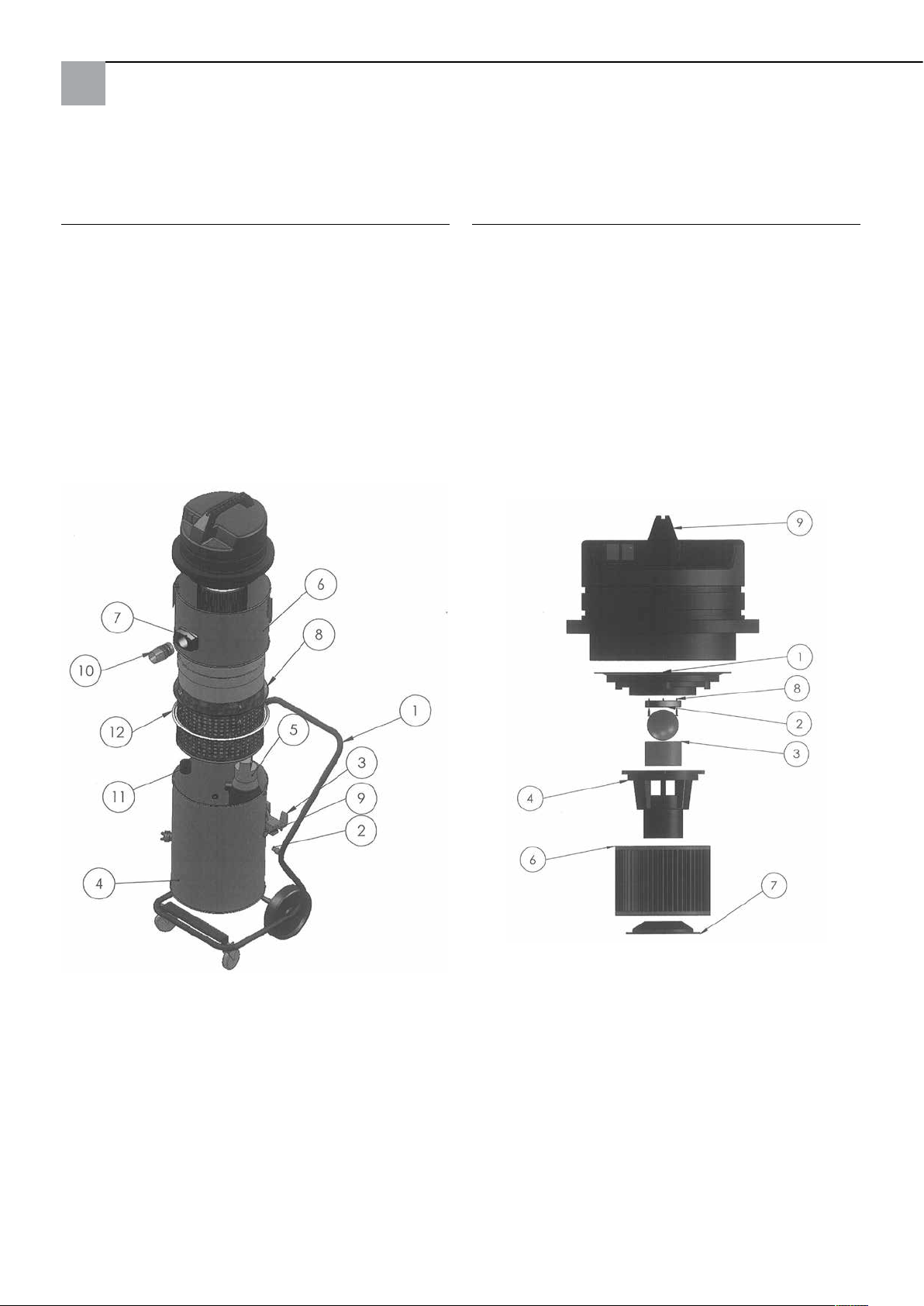
Vysokotlaké čistící zařízení
Krake 85 kompletní:
Sací hlava:
Pol. Označení Č. art.
1 Podvozek kompletní 65 80 11
2 Distanční kus pro sací přístroj 65 80 16
3 Sklápěcí zařízení 65 77 47
4 Kotel dole kompletní (bez čerpadla) 65 80 08
5 Ponorné čerpadlo 65 77 17
6 Nástavec ke kotli kompletní 65 80 09
7 Spojka ke kotli kompletní včetně
přívodního hrdla 65 80 13
8 Podpěrný koš filtru 65 80 12
9 Kabelové šroubení kompletní Krake 85 65 80 17
11 Objímka se zpětnou klapkou 65 80 14
12 Těsnění u podpěrného koše 65 77 20
Pol. Označení Č. art.
1 Upínací deska motoru 65 80 66
2 Těsnění vypínací koule 65 80 19
3 Filtrační síto 65 80 73
4 Plováková komora 65 80 72
5 Vypínací koule 65 80 21
6 Skládaný filtr C 65 77 25
7 Držák pro filtrační vložku 65 80 75
8 Šroub do třískové desky 3 x 20 65 80 22
9 Sací hlava 2.400W modrá kompletní 65 80 20
68
Page 69
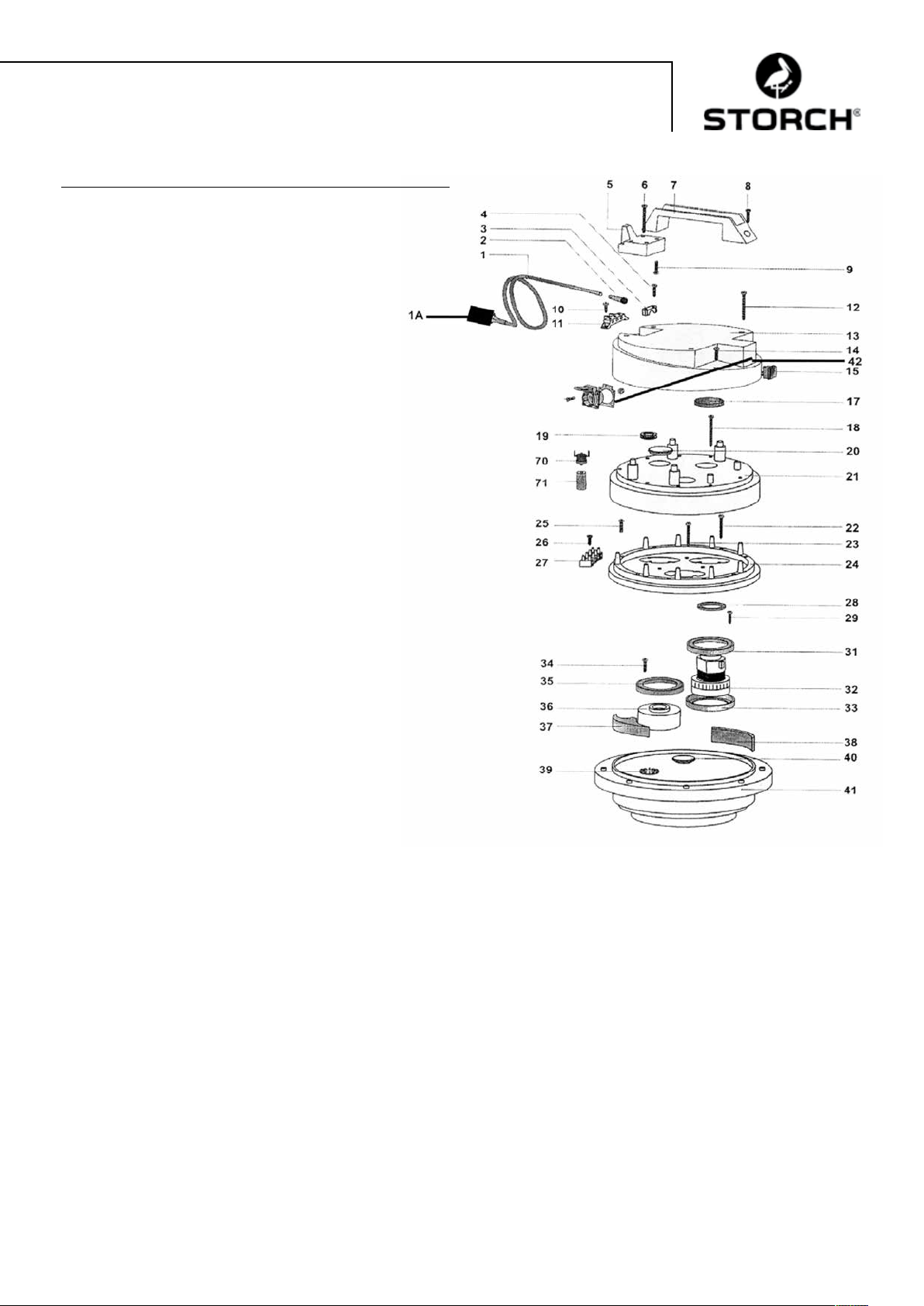
Sací hlava:
Pol. Označení Č. art.
1 Elektrický kabel 2 x 1,5, se zástrčkou 65 80 31
1a Zástrčka k ochraně osob IP 44 60 02 46
2 Kabelové vedení pro sací hlavu 65 80 33
3 Kabelová svorka pro sací hlavu 65 80 34
4 Křížový šroub M 5 x 20 65 80 35
5 Kabelový držák pro sací hlavu HDK 85 65 80 36
6 Šroub 5,2 x 50 65 80 37
7 Držadlo pro sací hlavu HDK 85 65 80 38
8 Křížový šroub M 5 x 35 65 80 39
9 Křížový šroub M 5 x 20 65 80 35
10 Křížový šroub M 5 x 14, 65 80 41
11 Připojovací svorka 65 80 42
12 Šroub 5,2 x 50 65 80 37
13 Kryt pro sací hlavu 65 80 43
14 Křížový šroub M 5 x 20 65 80 35
15 Spínač Zapnout / Vypnout pro sací hlavu 65 80 44
17 Filtr pro sací hlavu HDK 85 65 80 45
18 Šroub 5,2 x 50 65 80 37
19 Kabelový ochranný kroužek 65 80 47
20 Záslepka 65 80 48
21 Kryt motoru pro sací hlavu 65 80 49
22 Samořezný šroub 3 x 40 65 80 51
23 Samořezný šroub 3 x 40 65 80 51
24 Kroužek k uchycení sací hlavy 65 80 52
25 Křížový šroub M 5 x 30 65 80 53
26 Samořezný šroub 4,3 x 19 65 80 54
27 Připojovací svorka 4-pólová 65 80 55
28 Těsnicí kroužek 65 80 56
29 Křížový šroub M 5 x 20 65 80 35
31 Těsnění motoru pro sací hlavu 65 80 57
32 Motor pro HDK 85 65 80 03
33 Těsnění motoru pro sací hlavu 65 80 57
34 Křížový šroub M 5 x 20 65 80 35
35 Těsnění motoru pro sací hlavu 65 80 57
36 Distanční držák 65 80 61
37 Těsnící kus pro sací hlavu 65 80 62
38 Filtr 65 x 10, L = 120 65 80 63
39 Kotouč spojky 65 80 64
40 Krytka 65 80 65
41 Upínací deska motoru 65 80 66
42 Ochranná kontaktní zástrčka
pro sací hlavu 65 80 67
70 Termo spínač pro HDK 85 65 80 07
71 Držák pro termo kontakt 65 80 68
69
Page 70
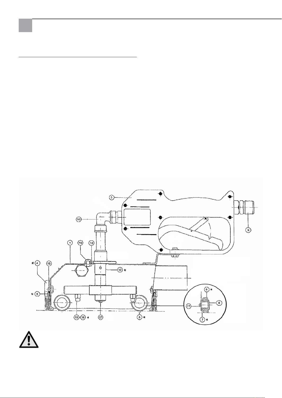
Standardní čistící poklop náhradní díly:
Pol. Označení Č. art.
1 Poklop 65 74 01
3 Vysokotlaký uzavírací ventil (novinka) 65 71 30
4 Sada čistících kartáčků, 4 dílná 65 74 18
6 Kolečko 65 74 04
7 Pouzdro ložiska 65 74 05
8 Čep ložiska 65 74 06
9 Připojovací vsuvka 65 71 21
10 Úhel 90 stupňů 65 71 23
12 Vyměnitelný díl uspořádání
trysek do bodů 65 75 51
12a Vyměnitelný díl uspořádání
trysek na plocho 65 75 52
15 Tryska 0,95 65 74 08
16 Tryska 1,27 (s drážkou) 65 74 19
17 Šroub s čočkovitou hlavou M4x8 65 74 12
18 Šroub s čočkovitou hlavou M5x10 65 74 13
bez obrázku
Teflonový váleček široký 65 75 54
Teploměr s lepícím kroužkem 65 75 53
* Díly podléhající opotřebení
POZOR
Doporučujeme použití přiložených trysek s průměrem 1,27 mm, pokud použité vysokotlaké čistící zařízení
čerpá více než 11 l vody za minutu.
70
Page 71

Příslušenství a náhradní díly:
Označení Č. art.
Profi - vysokotlaké čistící zařízení 135 barů 65 60 00
Profi - vysokotlaké čistící zařízení 220 barů,
benzín 65 60 50
Prodlužovací sací hadice kompl., 10m 65 70 10
Prodlužovací vysokotlaká hadice, 10 m,
tlakové zatížení do 400 barů, max. teplotní
zatížení 150° C 65 65 14
Prodlužovací vysokotlaká hadice, 10 m,
včetně dvojité spojovací vsuvky, tlakové zatížení
do 210 barů, max. teplotní zatížení 150° C 65 65 30
Spojení s dvojitou vsuvkou vysokotlaká
hadice M 22 x 1,5 65 65 31
Prodlužovací odtoková hadice 10 m 65 70 16
Držák hadice 64 24 25
Čistící poklop na malé plochy 6 x6 cm 65 76 50
Čsitící poklop na velké plochy 44 x40 cm 65 75 60
Zařízení na čištění podlah pro velké plochy
čistící poklop 65 75 80
Vodní nasávací tryska k nasávání vody 65 10 30
Sací trubka kov 1,2 m 65 10 10
Označení Č. art.
Náhradní díly odsavače:
Filtrační pytel na více použití z textilie 210 mµ 65 77 30
Filtrační pytel na více použití z textilie 300 mµ 65 77 31
Filtrační pytel na více použití z textilie 400 mµ 65 77 32
Spojka pro sací hadici 65 70 11
71
Page 72

Záruka
Záruční podmínky
U našich přístrojů platí zákonné záruční lhůty 12 měsíců od data zakoupení/data faktury obchodního konečného zákazníka. Pokud jsou delší lhůty v cestě námi vypsanému prohlášení o záruce, jsou zvláště vyznačeny v návodu k obsluze
příslušných přístrojů.
Uplatňování
V případě záručního příp. garančního případu žádáme, aby bylo zasláno kompletní zařízení dohromady s fakturou do
našeho střediska Logisitk Center v Berka nebo do námi autorizované servisní stanice.
Kontaktujte prosím nejdříve placený hotline servis firmy STORCH: +49 (0)202 . 49 20 – 110.
Nárok na záruku příp. garanci
Nároky na opravu vznikají výhradně v důsledku vady materiálu nebo výrobní vady a také výhradně při používání
přístroje v souladu s určeným účelem. Díly podléhající opotřebení jako těsnící kartáčky, otočná kolečka, vzduchový
filtr, těsnění, rotační tryska, filtr na více použití atd. nespadají mezi takové nároky. Veškeré nároky zanikají zamontováním dílů cizího původu, při nepřiměřeném zacházení a skladování a také při zřejmém nedodržování provozního návodu.
Provádění oprav
Veškeré opravy smějí být prováděny výhradně naším závodem nebo servisními stanicemi autorizovanými firmou
STORCH.
72
Page 73
Prohlášení o shodě ES
Název / adresa výstavce: STORCH Malerwerkzeuge & Profigeräte GmbH
Platz der Republik 6 - 8
D - 42107 Wuppertal
ve smyslu směrnice ES o strojích 2006/42 ES - příloha II A
Tímto prohlašujeme, že následně označený stroj
Označení stroje: Vysokotlaké čistící zařízení Krake 85
Typ stroje: Odsávač - mokré sání
Číslo výrobku: 65 80 00
odpovídá příslušným ustanovením následujících směrnic:
Směrnice o strojích: 2006 / 42 / EG
Směrnice o elektromagnetické
kompatibilitě: 2004 / 108 / EG
Zplnomocněnec k sestavení technických podkladů:
STORCH Malerwerkzeuge & Profigeräte GmbH
Platz der Republik 6 - 8
D-42107 Wuppertal
Holger Joest Jörg Heinemann
-Vedoucí Management produktů Technika + Servis - - Jednatel -
Wuppertal, v dubnu 2012
73
Page 74

747576
Page 75

Page 76
Art.-Nr. Bezeichnung
65 80 00 Hochdruck-Krake 85
65 80 05 Set Hochdruck-Krake 85
inkl. Pro-Hochdruckreiniger 135 bar
Art. nr. Beschrijving
65 80 00 Hogedrukkrake 85
65 80 05 Set Hogedrukkrake 85 incl.
professionele hogedrukreiniger 135 bar
Référence Désignation
65 80 00 Haute pression Krake 85
65 80 05 Set haute pression Krake 85
nettoyeur haute pression professionnel
135 bar incl.
N. art. Denominazione
65 80 00 Idropulitrice ad alta pressione Krake 85
65 80 05 Set Idropulitrice ad alta pressione Krake
85 incl. Gruppo detersore ad alta press.
Professionale 135 bar
Art. no. Description
65 80 00 High Pressure Water Recovery System 85
65 80 05 Set High Pressure Water Recovery System
85 incl. Professional high pressure cleaner
135 bar
Výr. č. Označení
65 80 00 Vysokotlaké čisticí zařízení Krake 85
65 80 05 Souprava vysokotlakého čisticího
zařízení Krake 85 vč. profesionálního
vysokotlakého čističe 135 bar
Malerwerkzeuge & Profigeräte GmbH
Platz der Republik 6 - 8
D-42107 Wuppertal
Telefon: +49 (0)2 02 . 49 20 - 0
Telefax: +49 (0)2 02 . 49 20 - 111
E-mail: [email protected]
H 002503
Internet: www.storch.de
04-2012
 Loading...