

Page 1

Aufbauanleitung Cover Quick® Wall
DE
Montagehandleiding Cover Quick
®
Wall
Instructions de montage Cover Quick
Istruzioni di montaggio Cover Quick
Cover Quick
Montážní pokyny Cover Quick
®
Wall installation manual
®
Wall
®
®
Wall
Wall
NL
FR
IT
GB
CZ
1
Page 2

DE
Vielen Dank
für Ihr Vertrauen zu STORCH. Mit dem Kauf haben Sie sich für ein Qualitäts-Produkt entschieden.
Haben Sie trotzdem Anregungen zur Verbesserung oder aber vielleicht einmal ein Problem, so freuen wir uns sehr,
von Ihnen zu hören.
Bitte sprechen Sie mit Ihrem Außendienst-Mitarbeiter oder in dringenden Fällen auch mit uns direkt.
Mit freundlichen Grüßen
STORCH Service Abteilung
Telefon: +49 (0)2 02 . 49 20 - 112
Fax: +49 (0)2 02 . 49 20 - 244
kostenlose Service-Hotline: 08 00. 7 86 72 47
kostenlose Bestell-Hotline: 08 00. 7 86 72 44
kostenloses Bestell-Fax: 08 00. 7 86 72 43
(nur innerhalb Deutschlands)
Inhaltsverzeichnis Seite
Lieferumfang Cover Quick® Wall Basis-Set 2
®
Lieferumfang Cover Quick
Hinweise zu Einsatz und Pflege der Cover Quick
Aufbau-Varianten mit dem Cover Quick
Aufbau-Varianten mit dem Cover Quick
Die einzelnen Elemente der Cover Quick
Aufbau einer Cover Quick
Aufbau einer Cover Quick
Aufbau einer Cover Quick
Abdecken der Cover Quick
Einsatz der Folientür 10
Garantie 11
Wall Erweiterungs-Set 3
®
Wall 3
®
Wall Basis-Set 4
®
Wall Erweiterungs-Set 4
®
Wall und ihre Funktionsweise 5
®
Wall Raumabtrennung 5 - 7
®
Wall Eckabtrennung 8 - 9
®
Wall in U-Form 9
®
Wall Konstruktionen 10
Lieferumfang Cover Quick® Wall Basis-Set (Art.-Nr. 56 55 00)
In der Tabelle Artikel-Nummern von Ersatzteilen und Verbrauchsmaterialien für Nachbestellungen
Anzahl Bezeichnung Art.-Nr.
4 CQ-Wall Teleskopstützen 56 55 20
1 Transport-Tragegriff für Teleskopstützen 56 55 25
1 Transporttasche 56 50 50
4 T-Verbindungsprofil 150 cm 56 55 17
4 T-Verbindungsprofil 100 cm 56 55 18
4 T-Verbindungsprofil 25 cm 56 55 19
2 U-Zwischenprofil 150 cm 56 55 14
2 U-Zwischenprofil 100 cm 56 55 15
2 U-Zwischenprofil 50 cm 56 55 16
6 Eckverbinder 56 55 13
4 Eckdichtung 70x70 mm 56 55 11
2 Boden- / Deckendichtung 80 x 80 mm 56 55 12
1 Rolle Maskenband 25 mm x 25 m 49 57 25
1 Rolle Reparaturband 48 mm x 50 m silber für die Folientürbefestigung 49 07 50
1 CQ-Folie mit Gewebeband 270 cm x 20 m K 20 cm 48 98 43
1 Folientür mit Reißverschluss 49 91 30
2
Page 3

Lieferumfang Cover Quick® Wall Erweiterungs-Set (Art.-Nr. 56 55 10)
Anzahl Bezeichnung Art.-Nr.
1 CQ-Wall Teleskopstütze 56 55 20
2 T-Verbindungsprofil 150 cm 56 55 17
2 T-Verbindungsprofil 25 cm 56 55 19
2 U-Zwischenprofil 150 cm 56 55 14
2 Eckverbinder 56 55 13
2 Boden- / Deckendichtung 80 x 80 mm 56 55 12
Hinweise zu Einsatz und Pflege der Cover Quick® Wall
Stellen Sie stets sicher, dass die zusammengebauten Elemente immer gut gesichert abgestellt und / oder fest montiert
werden! Durch lose und / oder nicht fest montierte Teile besteht Einsturzgefahr.
Vorsicht bei Decken mit hängender Konstruktion! Der Aufbau ist unter Umständen nicht möglich, da die Deckenprofile
und der durch die Teleskopstützen ausgeübte Druck die Deckenkonstruktion beschädigen kann und / oder nicht stabil
genug aufgebaut werden kann.
Prüfen Sie vor dem Aufbau die Beschaffenheit und Empfindlichkeit der Oberflächen (Wände, Boden und Decke)! Trotz
der weichen und farblosen Gummidichtungen der Profile übernehmen wir keine Haftung durch auftretende Schäden an
den Oberflächen. Prüfen Sie zur Sicherheit an einer unauffälligen Stelle die Reaktion auf den Druck der Gummidichtungen, indem Sie ein beliebiges Profil mit der Dichtungsseite auf die Oberfläche legen, etwas Druck ausüben und über
die Oberfläche reiben.
Bei starken Unebenheiten der Oberflächen oder bei dort installierten Anbauteilen wie Kabelleitungen, Heizungsrohre
oder Ähnliches kann es vorkommen, dass die Unebenheiten mit den Profilen nicht überbrückt werden können und das
Staubschutzsystem nicht dicht schließend installiert werden kann.
Stellen Sie immer sicher, dass alle Teile und Anbauelemente nicht beschädigt sind und tadellos funktionieren. Sollte
eins der Elemente kaputt- oder verloren gehen, sind sie unter oben angegebenen Art.-Nrn. nachbestellbar.
Reinigen Sie die Profile inkl. Dichtungen nach jeder Anwendung mit einem feuchten Reinigungstuch. Damit gewährleisten Sie eine sichere Verklebung der Klebebänder auf der Profiloberfläche und vermeiden eventuelle Verunreinigungen
der Wand-, Decken und Bodenoberflächen beim Aufbau.
Reinigen Sie ebenfalls die Teleskopstützen und deren Auflageplatten, um stets einen sicheren Halt zu gewährleisten.
Vermeiden Sie den Kontakt von Schmierstoffen diverser Art mit der Spannvorrichtung am Spannhebel. Die Spannkraft
kann dadurch gemindert werden.
3
Page 4

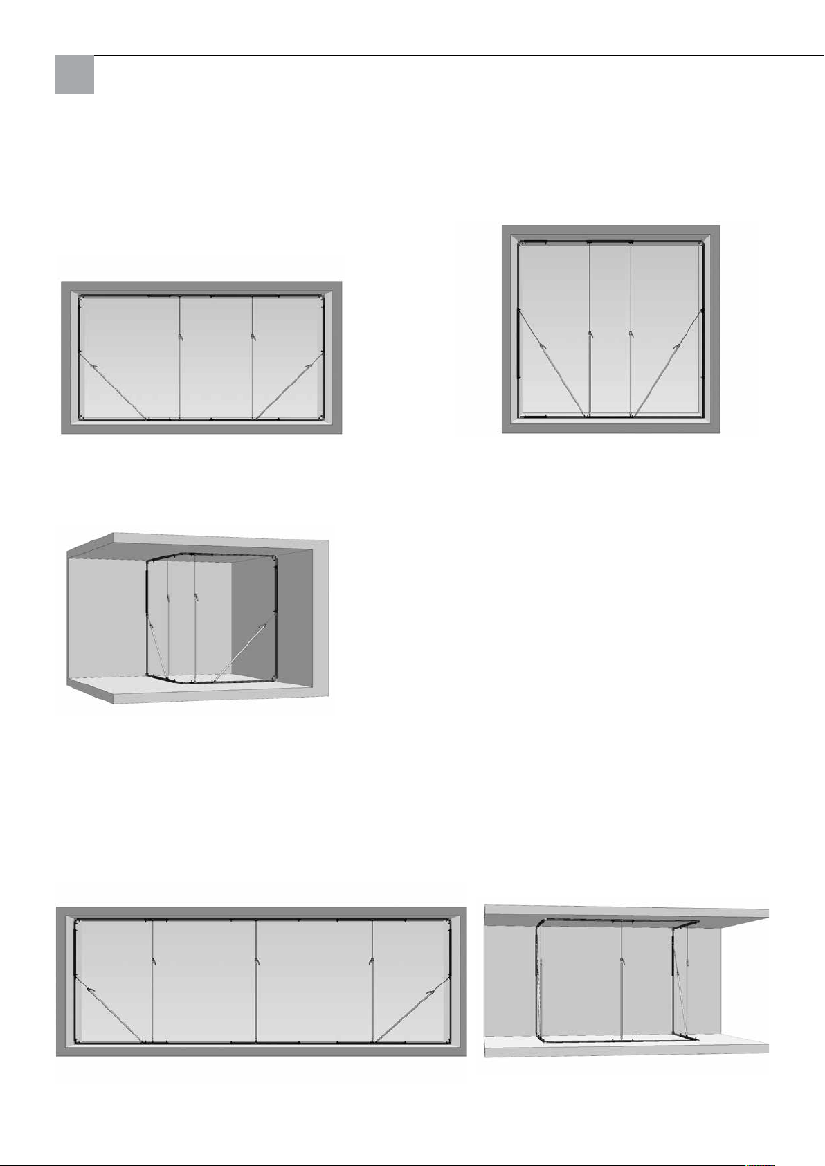
Aufbau-Varianten mit dem Cover Quick® Wall Basis-Set (Art.-Nr. 56 55 00)
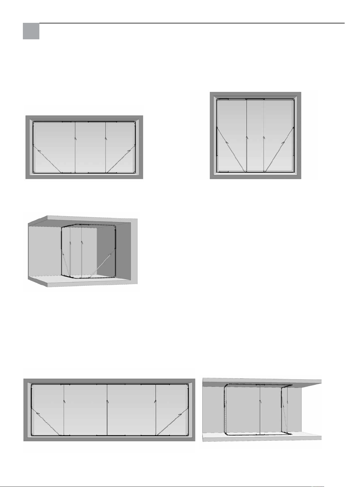
a) Raumabtrennungen
Maximal 2,70 m hoch und 5,30 m breit Maximal 3,80 m hoch x 4,00 m breit
b) Eckabtrennung
Maximal 2,70 m hoch, 3,40 m breit und 2,15 m tief
Die Maße der Abtrennungen sind beliebig stufenlos
anpassbar.
Aufbau-Varianten mit dem Cover Quick® Wall Erweiterungs-Set (Art.-Nr. 56 55 10)
Zusätzliche Aufbauvarianten und die Vergrößerung der vorgenannten Aufbauvarianten sind mit dem Erweiterungs-Set
möglich:
a) Erweiterung von Raumabtrennungen
Pro Erweiterungsset verbreitern Sie
Raumabtrennungen um jeweils 2,80 m
b) Beidseitige Ecklösungen (U-Form)
Maximal 2,70 m hoch x 2,65 m tief
x 3,40 m breit
4
Page 5

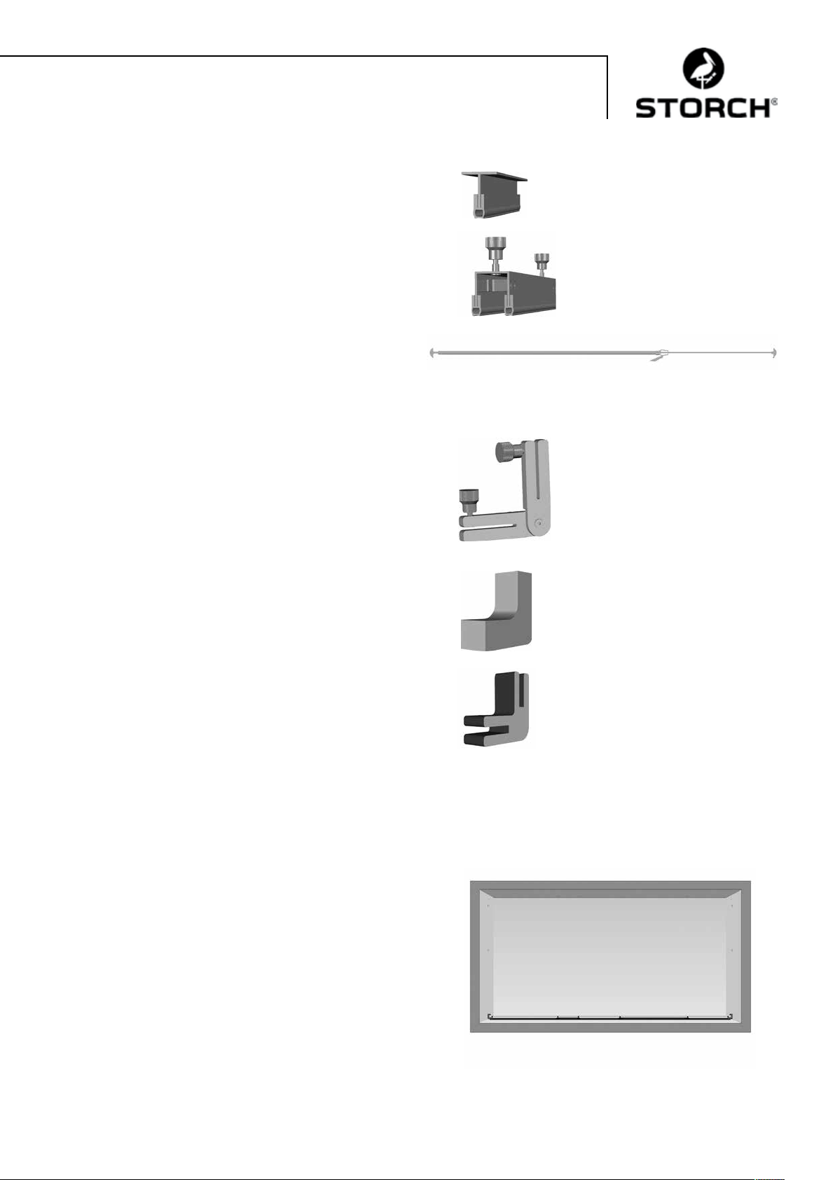
Die einzelnen Elemente der Cover Quick® Wall und ihre Funktionsweise
T-Verbindungsprofil (25, 100, 150 cm)
Grundsätzlich an den Enden der erstellten Konstruktionen
zu montieren zur nachträglichen Eckverbinder-Montage.
U-Zwischenprofil (50, 100, 150 cm)
Konstruktionselement, in das die T-Verbindungsprofile an
beiden Seiten reingeschoben und mit Feststellschrauben
fixiert werden.
Teleskopstütze (auf max. 380 cm ausziehbar)
Zur Fixierung der Konstruktion und Gewährleistung der
Dichtheit durch Druckausübung auf die Wand-, Bodenund Deckenkonstruktionen.
Eckverbinder
Zur Verbindung von Boden- und Decken- mit den Seitenkonstruktionen
Für den Aufbau abgewinkelter Seiten- oder Boden- bzw.
Deckenkonstruktionen
Montage ausschließlich außen an T-Verbindungsprofilen
Eckdichtung 70 x 70 mm
Zum Einklemmen zwischen Boden bzw. Decken und
Wänden und den Eckverbindern der Cover Quick Wall
®
zwecks Abdichtung und zusätzlichem Schutz der Oberflächen
Eckdichtung 80 x 80 mm
Zum Einbau in rechtswinkligen Boden- und Deckenverbindungen (Ecklösung und doppelte Ecklösung) unterhalb
der Eckverbindern zwecks Abdichtung der Konstruktion
Aufbau einer Cover Quick® Wall Raumabtrennung
a) Festlegung des abzutrennenden Bereiches
Dazu die T- und U-Profile im Wechsel auf den Boden legen, zusammenstecken und auf die gewünschte Länge ausziehen.
b) Zusammenbau von Boden- und Deckenelementen
Benötigte Elemente bei bis zu 5,30 m Aufbaubreite:
1 x T-Verbindungsprofil 150
2 x T-Verbindungsprofil 100
1 x U-Zwischenprofil 150,
1 x U-Zwischenprofil 50
Achten Sie darauf, dass an beiden Enden jeweils ein
T-Profil platziert ist, an dem Sie außen am Profil einen
Eckverbinder befestigen.
Die Konstruktion so auseinanderziehen, dass die Eckverbinder möglichst nah an den Wänden anliegen. Dann die
Fixierschrauben handfest anziehen.
5
Page 6

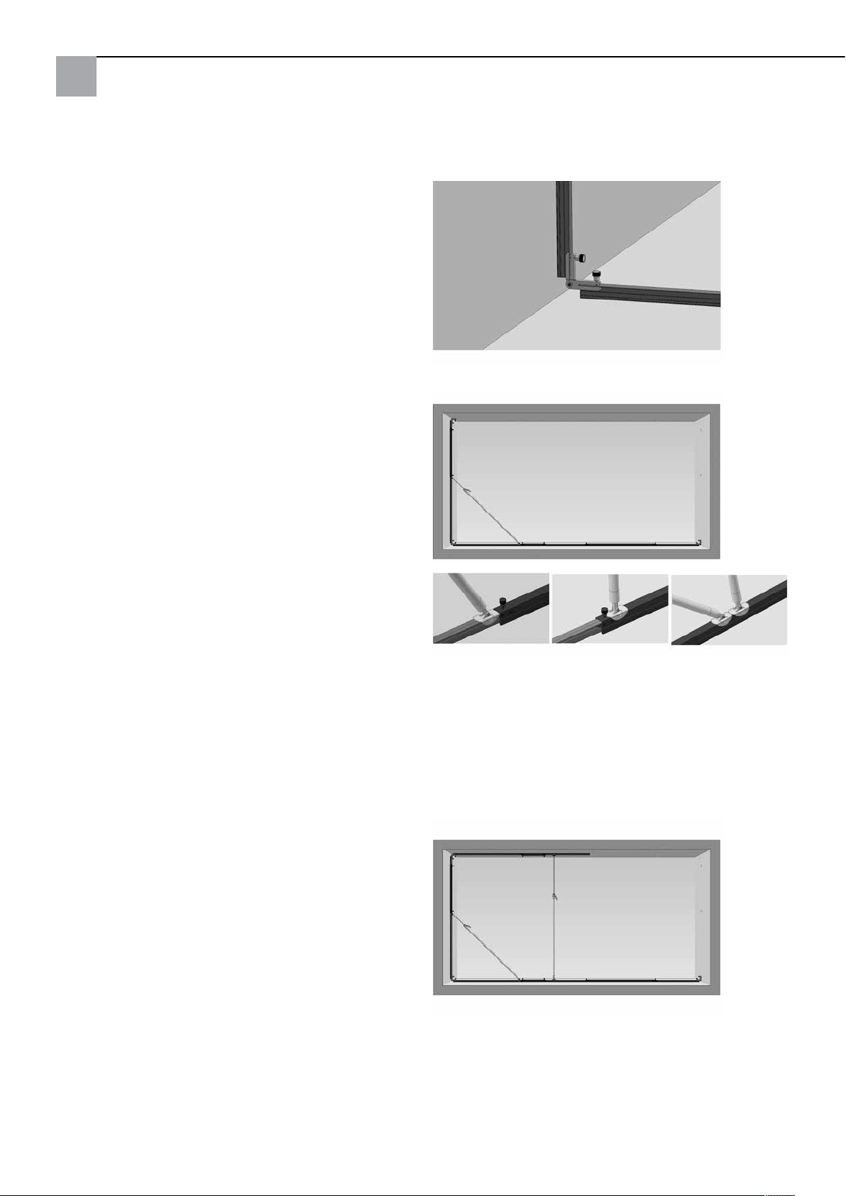
T-Profil Verbindung mit Eckverbinder
c) Zusammenbau der Seitenelemente
Benötigte Elemente bei bis zu 2,70 m Deckenhöhe:
1 x T-Verbindungsprofil 150
1 x U-Zwischenprofil 100
1 x T-Verbindungsprofil 25
Für den Aufbau der Seitenelemente T- und U-Profile so
verbinden, dass jeweils ein T-Profil an beiden Enden platziert wird. Am oberen Ende der Seitenelemente jeweils
auf der Außenseite einen Eckverbinder befestigen. Das
Seitenelement unten mit dem Eckverbinder des Bodenelementes verbinden, auf die gewünschte Höhe auseinanderziehen und danach die Fixierschrauben handfest anziehen.
d) Sicherung der Seitenelemente mit Teleskopstützen
Zur Sicherung des Seitenelementes platzieren Sie eine
Teleskopstütze schräg zwischen Boden- und Seitenelement.
Dazu platzieren Sie die Teleskopstütze mit den Auflagetellern auf den Oberseiten der Profile von Wand- und
Bodenelementen, ziehen das Innenrohr unter Lösung und
späterer Wieder-Einrastung der Feststellnasen auf die
passende Länge aus.
Zur Fixierung und Feineinstellung der Länge der Teleskopstützen betätigen Sie dann dessen Klemmgriff mehrmals bis die Auflageteller entweder von den Befestigungsschrauben der Profile, durch die Kanten der Übergänge von T- zu den U-Profilen oder an den Auflagefüßen
der senkrecht montierten Stützen gestoppt werden. Üben
Sie nur so viel Druck aus, wie nötig, um die Dichtheit der
Wandelemente zu gewährleisten.
Hinweis:
Zur Positionierung der Stütze: achten Sie darauf, dass die
Klemmgriffe der Teleskopstützen nach außen positioniert
werden. So stören die Griffe beim Abkleben der Profile
auf der Innenseite nicht.
e) Aufbau des Deckenelementes
Das Deckenelement stellen Sie in der gleichen Länge wie
das Bodenelement (ohne Eckverbinder) mit T-Profilen an
beiden Enden zusammen.
Zunächst verbinden Sie ein T- und ein U-Profil für ca. die
Hälfte der Deckendistanz miteinander.
Danach verbinden Sie das T-Element dieses Teilstücks
der Deckenkonstruktion mit dem Eckverbinder des Seitenelements und lassen es frei schwebend am Seitenelement hängen.
Anschließend stabilisieren Sie dieses freischwebende
Teilstück mittels Teleskopstütze, die Sie zwischen der
Decken- und der Bodenkonstruktion platzieren und ausfahren.
6
Page 7

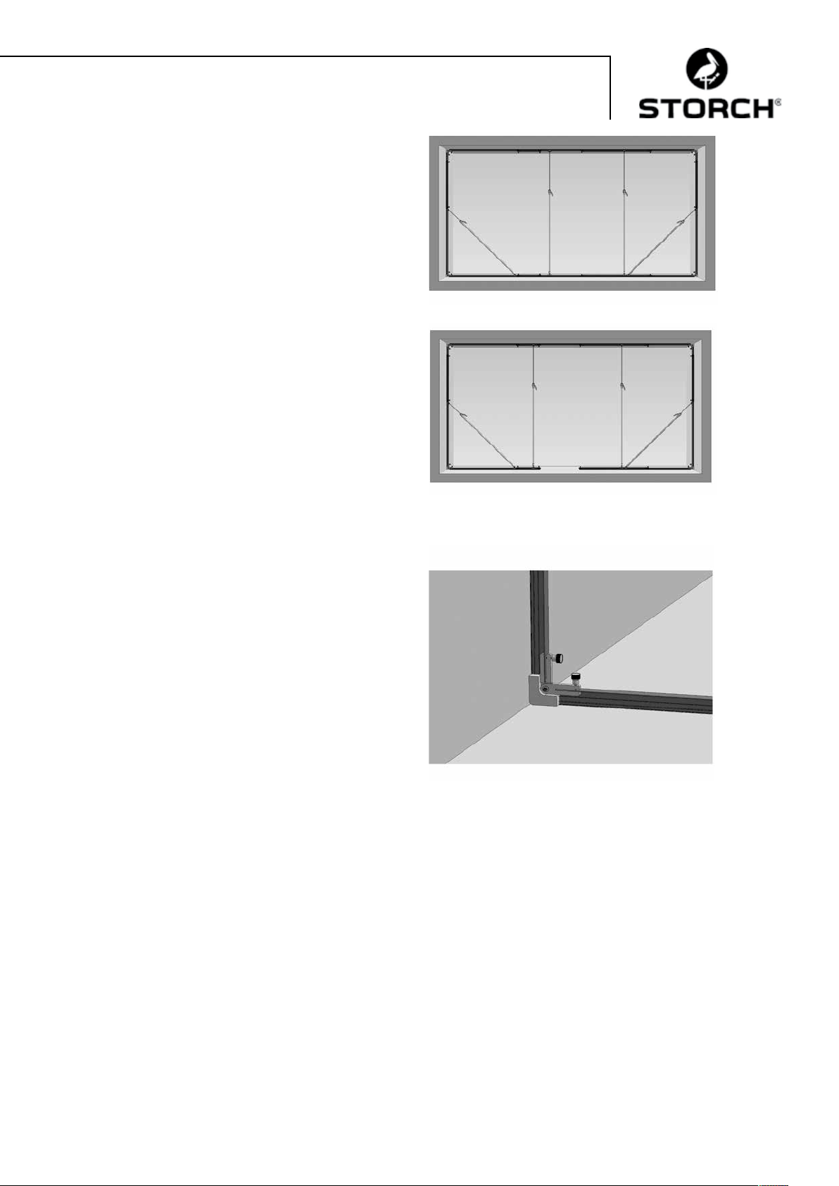
Die Profilelemente des Mittelteils der Deckenkonstruktion werden nach Aufbau des ersten Teilstückes so weit
wie möglich in dieses hineingeschoben.
Auf der gegenüberliegenden Seite verfahren Sie beim
Aufbau des Seiten- und dem Rest des Deckenelementes
gleichermaßen wie unter c. bis e. beschrieben.
Anschließend ziehen sie das Mittelteil aus dem bereits
aufgebauten ersten seitlichen Teilstück des Deckenelementes heraus, verbinden es mit dem gegenüberliegenden Teilstück und ziehen die Fixierschrauben an.
Hinweis:
Sollten Sie Bedarf haben, den abgetrennten Bereich zu
befahren, können Sie aus dem Bodenelement auch ein
Profilstück entnehmen.
f) Feinjustierung und Sicherung
Klemmen Sie außen an den vier Ecken oben und unten
die Eck-Dichtungen (70 x 70) ein, dass sie an der Seite,
die nachträglich mit der CQ-Folie beklebt wird, möglichst
nicht überstehen und plan zur Profiloberfläche positioniert
sind.
Zur optimalen Platzierung der Eckdichtungen und für die
Feinjustierung der Cover Quick Wall® richten Sie sie aus,
indem Sie die Schraubverbindungen zwischen den Profilen leicht lösen und die Profile auf die passende Länge
raus- oder reinschieben.
Prüfen Sie die gleichmäßige Auflage der Dichtungen von
U- und T-Profilen auf Wand-, Decken- oder Bodenflächen. Sollten die Profildichtungen die Oberflächen nicht
bündig abschließen, versetzen Sie eine der Stützen so,
dass der Druck gleichmäßiger verteilt wird und die Dichtheit gewährleistet wird.
Ziehen Sie anschließend für einen stabilen Stand alle
Fixierschrauben fest nach und überprüfen den sicheren
Sitz der Teleskopstützen.
7
Page 8

Aufbau einer Cover Quick® Wall Eckabtrennung
a) Festlegung des abzutrennenden Bereiches
Dazu die erforderlichen U- und T-Profile zusammenstecken, im rechten Winkel zueinander auf den Boden legen und
auf die gewünschte Länge ausziehen.
b) Zusammenbau von Boden- und Deckenelementen
Benötigte Elemente bei maximal 2,70 m Höhe, 3,40 m
Breite und 2,15 m Tiefe
Seite 1:
2 x T-Verbindungsprofil 100
1 x U-Zwischenprofil 150
Seite 2:
1 x T-Verbindungsprofil 25
1 x T-Verbindungsprofil 150
1 x U-Zwischenprofil 50
An den beiden Enden der Schenkel der Bodenkonstruktion muss jeweils ein T-Profil platziert sein.
An den beiden äußeren Teilstücken der Bodenkonstruktion, die auf die Wände gerichtet sind, befestigen Sie je
einen Eckverbinder an der Oberseite des T-Profils. Damit
werden später die Seitenelemente verbunden.
Verbinden Sie danach die im rechten Winkel zueinander
liegenden beiden Schenkel der Bodenkonstruktion mit
einem Eckverbinder, den Sie mit den Feststellschrauben
oberhalb der Dichtlippen an den T-Profilen fixieren.
Die Bodenkonstruktion danach so auseinanderziehen,
dass die Eckverbinder möglichst nah an den Wänden
anliegen und danach alle Feststellschrauben handfest
anziehen.
c) Aufbau und Fixierung von Seitenelementen
Der nachfolgende Aufbau und die Fixierung der Seitenelemente mittels Teleskopstützen erfolgt wie unter
„Aufbau einer Cover Quick Wall® Raumabtrennung“ c)
beschrieben.
Achten Sie darauf, am oberen Ende der Seitenkonstruktion einen Eckverbinder anzubringen, den Sie nachfolgend
mit der Deckenkonstruktion verbinden.
8
Page 9

d) Aufbau und Fixierung der Deckenelemente
Die beiden Schenkel der Deckenkonstruktion stellen Sie
in der gleichen Länge wie die der Bodenkonstruktion mit
T-Profilen an beiden Enden zusammen. Fixieren Sie diese
handfest mit den Feststellschrauben.
Danach verbinden Sie das äußere T-Verbindungsprofil des
ersten Schenkels der Deckenkonstruktion mit dem Eckverbinder des Seitenelements und stabilisieren anschließend dieses freischwebende Teilelement mittels Teleskopstütze, die Sie zwischen der Decken- und der Bodenkonstruktion platzieren und ausfahren.
Gleichermaßen verfahren Sie an der gegenüberliegenden
Seite mit Seiten- und Deckenelement.
Anschließend verbinden Sie die beiden Schenkel der
Deckenkonstruktion mit einem Eckverbinder, den Sie mit
den Feststellschrauben am T-Profil unterhalb der Dichtlippen fixieren.
e) Feinjustierung und Sicherung
Gehen Sie hierzu wie unter Punkt f des „Aufbaus der
Cover Quick Wall® Wandabtrennung“ vor.
Zusätzlich klemmen Sie an an den rechtswinkligen Verbindungsstellen der Boden- und der Deckenkonstruktion unterhalb der Eckverbinder zwei 80 x 80 Boden- /
Deckendichtungen in die T-Profile ein, indem Sie die 80
x 80 Eckdichtung mit den dafür vorgesehenen Schlitzen
über die T-Profile überziehen.
Aufbau der Cover Quick® Wall in U-Form
Hierfür wird zusätzlich zum Basis-Set das Cover Quick
Wall® Erweiterungs-Set (Art.-Nr. 56 55 10) benötigt.
Zum Aufbau orientieren Sie sich am Aufbau einer Ecklösung. Die Aufbau-Reihenfolge ist identisch und entspricht
einer doppelten Ecklösung.
9
Page 10

Abdecken der Cover Quick® Wall Konstruktionen
Empfohlen wird der Einsatz von Cover Quick® und Maskenband. Wand- und Boden-Profile auf der Baustellenseite mit
Maskenband abkleben.
Cover Quick® auf der Baustellen-Innenseite auf den Decken-Konstruktionen aufkleben, ausfalten und seitlich mit dem
Masken- oder dem Reparaturband fixieren. Alternativ kann auch mit Folie abgedeckt werden.
Hinweis:
Durch die Abdeckung auf der Innenseite der Konstruktion, vermeiden Sie die direkte Verschmutzung der Elemente der
Cover Quick® Wall.
Einsatz der Folientür
Mit der Folientür mit Reißverschluss entsteht ein wiederverschließbarer Zugang zum Arbeitsbereich: Zunächst einen
passenden Türrahmen mit dem Maskenband auf der Folie abkleben. Darauf die Folientür aufkleben und überschüssige
Folie mit dem Cuttermesser oder einer Schere entfernen.
10
Page 11

Garantie
Garantiebedingungen
Für unsere Geräte gelten die gesetzlichen Gewährleistungsfristen von 12 Monaten ab Kaufdatum / Rechnungsdatum
des gewerblichen Endkunden.
Geltendmachung
Bei Vorliegen eines Gewährleistungs- bzw. Garantiefalles bitten wir, dass das komplette Gerät zusammen mit der
Rechnung frei an unser Logistik Center in Berka oder an eine von uns autorisierte Service-Station eingeschickt wird.
Zuvor bitten wir Sie, uns unter unserer kostenlosen STORCH Service-Hotline 08 00. 7 86 72 47 zu kontaktieren.
Gewährleistungs- bzw. Garantieanspruch
Ansprüche bestehen ausschließlich an Werkstoff- oder Fertigungsfehler sowie ausschließlich bei bestimmungsgemäßer
Verwendung des Geräts. Verschleißteile fallen nicht unter die Garantieansprüche. Sämtliche Ansprüche erlöschen durch
den Einbau von Teilen fremder Herkunft, bei unsachgemäßer Handhabung und Lagerung sowie bei offensichtlicher
Nichtbeachtung der Betriebsanleitung.
Durchführung von Reparaturen
Sämtliche Reparaturen dürfen ausschließlich durch unser Werk oder von STORCH autorisierten Service-Stationen
durchgeführt werden.
11
Page 12

NL
Hartelijk dank
voor uw vertrouwen in STORCH. Met deze aankoop hebt u voor een kwaliteitsproduct gekozen.
Als u desondanks een tip voor verbeteringen hebt of wellicht ooit een probleem ondervindt, dan horen wij graag van u.
Neem contact op met de medewerker buitendienst of in dringende gevallen rechtstreeks met ons.
Met vriendelijke groeten,
STORCH serviceafdeling
Tel.: +49 (0)2 02 . 49 20 - 112
Fax: +49 (0)2 02 . 49 20 - 244
Gratis service-hotline: 08 00. 7 86 72 47
Gratis bestel-hotline: 08 00. 7 86 72 44
Gratis bestel-fax: 08 00. 7 86 72 43
(alleen binnen Duitsland)
Inhoudsopgave Pagina
Levering Cover Quick® Wall basisset 12
®
Levering Cover Quick
Richtlijnen voor gebruik en onderhoud van de Cover Quick
Opbouwvarianten met de Cover Quick
Opbouwvarianten met de Cover Quick
De afzonderlijke elementen van de Cover Quick
Opbouw van een Cover Quick
Opbouw van een Cover Quick
Opbouw van een Cover Quick
Afdekken van de Cover Quick
Gebruik van de foliedeur 20
Garantie 21
Wall uitbreidingsset 13
®
Wall 13
®
Wall basisset 14
®
Wall uitbreidingsset 14
®
Wall en hun werking 15
®
Wall ruimteafscheiding 15 - 17
®
Wall hoekafscheiding 18 - 19
®
Wall in U-vorm 19
®
Wall constructies 20
Levering Cover Quick® Wall basisset (art.-nr. 56 55 00)
In de tabel vindt u artikelnummers van vervangende onderdelen en verbruiksmaterialen voor nabestellingen
Aantal Omschrijving Art.-nr.
4 CQ-Wall telescoopsteun 56 55 20
1 Transportgreep voor telescoopsteun 56 55 25
1 Transporttas 56 50 50
4 T-verbindingsprofiel 150 cm 56 55 17
4 T-verbindingsprofiel 100 cm 56 55 18
4 T-verbindingsprofiel 25 cm 56 55 19
2 U-tussenprofiel 150 cm 56 55 14
2 U-tussenprofiel 100 cm 56 55 15
2 U-tussenprofiel 50 cm 56 55 16
6 Hoekverbinder 56 55 13
4 Hoekdichting 70x70 mm 56 55 11
2 Vloer- / plafonddichting 80 x 80 mm 56 55 12
1 Rol maskeerband 25 mm x 25 m 49 57 25
1 Rol reparatieband 48 mm x 50 m zilver voor de foliedeurbevestiging 49 07 50
1 CQ-folie met textieltape 270 cm x 20 m K 20 cm 48 98 43
1 Foliedeur met ritssluiting 49 91 30
12
Page 13

Levering Cover Quick® Wall uitbreidingsset (art.-nr. 56 55 10)
Aantal Omschrijving Art.-nr.
1 CQ-Wall telescoopsteun 56 55 20
2 T-verbindingsprofiel 150 cm 56 55 17
2 T-verbindingsprofiel 25 cm 56 55 19
2 U-tussenprofiel 150 cm 56 55 14
2 Hoekverbinder 56 55 13
2 Vloer- / plafonddichting 80 x 80 mm 56 55 12
Richtlijnen voor gebruik en onderhoud van de Cover Quick® Wall
Controleer altijd of de gemonteerde elementen goed gezekerd worden geplaatst en / of stevig worden gemonteerd! Bij
losse en / of niet vast gemonteerde onderdelen ontstaat er gevaar voor instorting.
Pas op bij plafonds met hangende constructie! Opbouw is in bepaalde gevallen niet mogelijk omdat door de plafondprofielen en vanwege de druk van de telescoopsteunen de plafondconstructie beschadigd kan worden en / of niet stabiel
genoeg kan worden opgebouwd.
Controleer voor de opbouw de gesteldheid en gevoeligheid van de oppervlakken (muren, vloeren en plafonds)! Ondanks
de zachte en kleurloze rubberdichtingen van de profielen zijn wij niet aansprakelijk voor optredende schade aan de
oppervlakken. Controleer voor de zekerheid op een onopvallende plaats de reactie op de druk van de rubberdichtingen
door een profiel met de dichtingskant op het oppervlak legt, een beetje druk uitoefent en over het oppervlak wrijft.
Bij grote oneffenheden van de oppervlakken of bij geïnstalleerde onderdelen zoals kabelleidingen, verwarmingsbuizen
enzovoort kan het voorkomen dat de oneffenheden niet met de profielen kunnen worden overbrugd en het stofbeschermingssysteem niet sluiten kan worden geïnstalleerd.
Controleer altijd of alle onderdelen en aanbouwelementen onbeschadigd zijn en naar behoren functioneren. Als één van
de elementen defect of kwijt is, kan dit met de bovengenoemde artikelnummers worden besteld.
Reinig de profielen incl. dichtingen na elk gebruik met een vochtige reinigingsdoek. Zo garandeert een goede plakwerking van de plakbanden op de profieloppervlakken en voorkomt u eventuele verontreiniging van de muur-, plafond en
vloeroppervlakken bij de opbouw.
Reinig ook de telescoopsteunen en de ondersteuningsschijven om altijd een veilige grip te garanderen. Voorkom contact van de smeerstoffen van met de spanvoorziening op de spanhendel. De spankracht kan hierdoor worden verminderd.
13
Page 14

Opbouwvarianten met de Cover Quick® Wall basisset (art.-nr. 56 55 00)
a) Ruimteafscheidingen
Maximaal 2,70 m hoog en 5,30 m breed Maximaal 3,80 m hoog x 4,00 m breed
b) Hoekafscheiding
Maximaal 2,70 m hoog, 3,40 m breed en 2,15 m diep
De maten van de afscheidingen zijn naar wens traploos
aanpasbaar.
Opbouwvarianten met de Cover Quick® Wall uitbreidingsset (art.-nr. 56 55 10)
Met de uitbreidingsset zijn extra opbouwvarianten en vergroting van de genoemde opbouwvarianten mogelijk:
a) Uitbreiding van ruimteafscheidingen
Per uitbreidingsset vergroot u de ruimteafscheidingen
met telkens 2,80 m
b) Hoekoplossingen aan beide zijden
(U-vorm)
Maximaal 2,70 m hoog x 2,65 m diep
x 3,40 m breed
14
Page 15

De afzonderlijke elementen van de Cover Quick® Wall en hun werking
T-verbindingsprofiel (25, 100, 150 cm)
Aan de einden van de gemaakte constructies te monteren
voor latere montage van hoekverbinders.
U-tussenprofiel (50, 100, 150 cm)
Constructie-element waarin de T-verbindingsprofielen
aan beide zijden worden ingeschoven en met borgschroeven worden vastgezet.
Telescoopsteun (tot max. 380 cm uittrekbaar)
Voor vastzetten van de constructie en garanderen van
dichtheid door uitoefening van de druk op de muur-, vloer- en plafondconstructies.
Hoekverbinder
Voor het verbinden van vloer- en plafond- met de zijconstructies
Voor opbouw van gebogen zij- of vloer- resp. plafondconstructies
Montage uitsluitend buiten aan T-verbindingsprofielen
Hoekdichting 70x70 mm
Voor inklemmen tussen plafond resp. plafond en muren
en de hoekverbinders van de Cover Quick Wall
afdichting en extra bescherming van de oppervlakken
Hoekdichting 80x80 mm
Voor inbouw in rechtshoekige plafond- en plafondverbindingen (hoekoplossing en dubbele hoekoplossing) onder
de hoekverbinders voor afdichting van de constructie
®
voor
Opbouw van een Cover Quick® Wall ruimteafscheiding
a) Bepaling van het af te scheiden gedeelte
De T- en U-profielen op de vloer leggen, samenvoegen en tot de gewenste lengte uittrekken.
b) Samenvoegen van vloer- en plafondelementen
Benodigde elementen bij opbouwbreedte tot 5,30 m:
1 x T-verbindingsprofiel 150
2 x T-verbindingsprofiel 100
1 x U-tussenprofiel 150,
1 x U-tussenprofiel 50
Let erop dat aan beide kanten elk een T-profiel is
geplaatst waaraan u buiten aan het profiel een hoekverbinder bevestigt.
Trek de constructie zodanig uit elkaar dat de hoekverbinders zich zo dicht mogelijk bij de muren bevinden. Draai
vervolgens de borgschroeven handvast aan.
15
Page 16

T-profiel verbinding met hoekverbinders
c) Samenvoegen van de zij-elementen
Benodigde elementen bij plafondhoogte tot 2,70 m:
1 x T-verbindingsprofiel 150
1 x U-tussenprofiel 100
1 x T-verbindingsprofiel 25
Voor de opbouw van de zij-elementen de T- en U-profielen zodanig verbinden dat er telkens een T-profiel aan
beide kanten wordt geplaatst. Bevestig aan het bovenste
einde van de zij-elementeen telkens een hoekverbinder
aan de buitenkant. Verbind het zij-element onder met
de hoekverbinder van het vloerelement, op de gewenste
hoogte uittrekken en daarna de borgschroeven handvast
vastdraaien.
d) Zekering van de zij-elementen met telescoopsteunen
Voor de zekering van de zij-elementen plaatst u een telescoopsteun schuin tussen het vloer- en zij-element.
Hiertoe plaats u de telescoopsteunen met de ondersteuningsschijven op de bovenkanten van de profielen van de
muur- en vloerelementen; trek vervolgens de binnenbuis
tot de passende lengte uit door de vergrendeling los te
maken en vervolgens weer vast te zetten.
Voor het vastzetten en de exacte instelling van de lengte
van de telescoopsteunen drukt u meerdere keren op de
klemgreep tot de ondersteuningsschijven door de bevestigingsschroeven van de profielen, de kanten van de
overgang van T- naar de U-profielen of op de steunvoet
van de verticaal gemonteerde steunen worden gestopt.
Gebruik niet meer druk dan noodzakelijk is om de dichtheid van de muurelementen te garanderen.
Tip:
Voor positionering van de steunen: let erop dat de klemgrepen van de telescoopsteunen naar buiten worden
gepositioneerd. Zo storen de grepen niet bij het afplakken
van de profielen aan de binnenkant.
e) Opbouw van het plafondelement
Plaats het plafondelement in de gelijke lengte als het
vloerelement (zonder hoekverbinders) met T-profielen aan
beide einde.
Vervolgens koppelt u een T- en een U-profiel voor ca. de
helfte van de plafondafstand aan elkaar.
Hierna verbindt u het T-element van dit deel van de plafondconstructie met de hoekverbinder van het zij-element
en laat u het vrij zwevend aan het zij-element hangen.
Vervolgens stabiliseert u dit vrijzwevende stuk met de
telescoopstukken die u tussen de plafond- en de vloerconstructie plaatst en uitschuift.
16
Page 17

De profielelementen van het middendeel van de plafondconstructie worden na opbouw van de eerste deelstuk
hier zo ver mogelijk ingeschoven.
Ga aan de tegenoverliggende zijde bij de opbouw van de
zijkant- en de rest van het plafondelementen op dezelfde
wijze te werk als beschreven onder c. tot en met e.
Vervolgens trekt u het middendeel uit het reeds opgebouwde eerste zijdeel van het plafondelement, koppelt u dit
met aan het tegenoverliggende deel en draait u de borgschroeven aan.
Tip:
Als u in het afgescheiden gedeelte wilt rijden, dan kunt u
uit het vloerelement ook een profielstuk verwijderen.
f) Exacte instelling en zekering
Klem de hoekdichtingen (70 x 70) buiten aan de vier hoeken boven en onder vast; zorg ervoor dat ze aan de zijkant waar later de CQ-folie wordt geplakt niet oversteken
en gelijk met de profieloppervlakken worden geplaatst.
Voor optimale plaatsing van de hoekdichtingen en de
exacte instelling van de Cover Quick Wall
®
lijnt u de
hoekdichtingen uit door de schroefverbindingen tussen de
profielen een beetje los te maken en de profielen op de
passende lengte naar buiten of binnen te schuiven.
Controleer de gelijkmatige plaatsing van de dichtingen
van U- en T-profielen op muur-, plafond- of vloervlakken.
Als de profieldichtingen de oppervlakken niet gelijkliggend afsluiten, verplaatst dan één van de steunen zodanig dat de druk gelijkmatiger wordt verdeeld en de dichtheid wordt gegarandeerd.
Draai hierna voor een stabiele plaatsing alle borgschroeven vast aan en controleer de veilige stand van de telescoopsteunen.
17
Page 18

Opbouw van een Cover Quick® Wall hoekafscheiding
a) Bepaling van het af te scheiden gedeelte
De vereiste U- en T-profielen samenvoegen, in een rechte hoek ten opzichte van elkaar op de vloer leggen en op de
gewenste lengte uittrekken.
b) Samenvoegen van vloer- en plafondelementen
Benodigde elementen bij maximaal 2,70 m hoogte, 3,40
m breedte en 2,15 m diepte
Pagina 1:
2 x T-verbindingsprofiel 100
1 x U-tussenprofiel 150
Pagina 2:
1 x T-verbindingsprofiel 25
1 x T-verbindingsprofiel 150
1 x U-tussenprofiel 50
Aan de beide einden van de poten van de vloerconstructie
moet elk een T-profiel zijn geplaatst.
Aan de beide buitenste delen van de vloerconstructie die
naar de muren zijn gericht, bevestigt u elk een hoekverbinder aan de bovenkant van het T-profiel. Hiermee worden later de zij-elementen verbonden.
Koppel hierna de beide poten van de vloerconstructie, die
in een rechte hoek ten opzichte van elkaar liggen, aan
een hoekverbinder die u met de borgschroeven boven de
dichtingslippen aan de T-profielen vastzet.
Trel de vloerconstructie hierna zodanig uit elkaar dat de
hoekverbinders zo dicht mogelijk bij muur zijn en draai
hierna alle borgschroeven handvast aan.
c) Opbouw en vastzetten van zij-elementen
De onderstaande opbouw en vastzetting van de zij-elementen met telescoopsteunen verloopt zoals beschreven
onder "Opbouw van een Cover Quick Wall
®
ruimteafschei-
ding" c).
Zorg ervoor dat u aan het bovenste einde van de zijconstructie een hoekverbinder aanbrengt die u vervolgens
met de plafondconstructie verbindt.
18
Page 19

d) Opbouw en vastzetten van de plafondelementen
Voeg de beide poten van de plafondconstructie in de gelijke lengte als die van de vloerconstructie met T-profielen
aan beide einde samen. Zet deze handvast met de borgschroeven.
Hierna koppelt u het buitenste T-verbindingsprofiel van
de eerste poot van de plafondconstructie met de hoekverbinder van het zij-element en stabiliseert u hierna dit vrijzwevende element met een telescoopsteun die u tussen
de plafond- en de vloerconstructie plaatst en uitschuift.
Ga op dezelfde wijze te werk aan de tegenoverliggende
kant met het zij- en plafondelement.
Vervolgens koppelt u de beide poten van de plafondconstructie met een hoekverbinder, die u met de borgschroeven aan het T-profiel onder de dichtingslippen
vastzet.
e) Exacte instelling en zekering
Ga hiertoe te werk zoals beschreven onder punt f van
"Opbouw van de Cover Quick Wall
®
muurafscheiding".
Vervolgens klemt u op de verbindingsplekken van de vloer- en plafondconstructie onder de hoekverbinders twee
80 x 80 vloer- / plafonddichtingen in de T-profielen
vast, waarbij u de 80 x 80 hoekdichting met de hiervoor
bestemde spleten over de T-profielen trekt.
Opbouw van de Cover Quick® Wall in U-vorm
Hiervoor is naast de basisset de Cover Quick Wall® uitbreidingsset (art.-nr. 56 55 10) vereist.
Richt u bij het opbouwen op de opbouw van een hoekoplossing. De opbouwvolgorde is identiek en komt overeen
met een dubbele hoekoplossing.
19
Page 20

Afdekken van de Cover Quick® Wall constructies
Wij raden het gebruik van Cover Quick® en afplakband aan. Plak de wand- en bodemprofielen aan de bouwplaatskant
met afplakband af.
Cover Quick® aan de bouwplaats-binnenzijde op de plafondconstructie plakken, uitvouwen en aan de zijkant met de
afplak- of de reparatieband vastzetten. U kunt ook folie gebruiken voor het afdekken.
Tip:
Dankzij de afdekking aan de binnenzijde van de constructie voorkomt u directe vervuiling van de elementen van de
Cover Quick® Wall.
Gebruik van de foliedeur
Met de foliedeur met ritssluiting ontstaat er een afsluitbare toegang tot de werkplek: plak eerst een passend deurkozijn
met de afplakband op de folie af. Plak vervolgens de foliedeur en verwijder de overtollige folie met het Cutter-mes of
een schaar.
20
Page 21
Garantie
Garantievoorwaarden:
Voor onze apparaten gelden de wettelijke garantieperioden van 12 maanden vanaf aankoopdatum/factuurdatum van
de eindklant. Indien wij langere perioden in een garantieverklaring hebben toegezegd, dan worden deze speciaal in de
gebruiksaanwijzingen van de desbetreffende apparaten toegelicht.
Indienen van garantieclaims:
Bij een garantieclaim vragen wij u het gehele apparaat samen met de rekening franco aan ons logistiekcentrum in Berka of naar een door ons geautoriseerd servicestation te verzenden.
Neem eerst contact op met de STORCH Service-Hotline (hiervoor worden kosten in rekening gebracht):
+49 (0)202 . 49 20 – 110.
Garantieclaims
Claims uitsluitend met betrekking tot materiaal- of productiefouten en uitsluitend bij gebruik van het apparaat conform
de voorschriften. Voor slijtdelen gelden deze aanspraken niet. Alle claims vervallen bij inbouw van onderdelen van
externe herkomst, bij verkeerde hantering en opslag en bij het klaarblijkelijk niet in acht nemen van de gebruiksaanwijzing.
Reparaties uitvoeren
Reparaties mogen uitsluitend door onze fabriek of door STORCH geautoriseerde servicestations worden uitgevoerd.
21
Page 22
FR
Nous vous remercions
de la confiance dont vous témoignez envers STOCH. Avec cet achat vous avez opté pour un produit de
qualité. Si vous avez malgré tout des suggestions pour l‘amélioration ou si vous deviez rencontrer un problème, nous
sommes avec plaisir à votre disposition.
Dans ce cas, contactez votre représentant, ou directement notre service clients, s‘il s‘agit d‘un problème urgent.
Salutations dévouées
SAV STORCH
Tél.: +49 (0) 2 02 . 49 20 - 112
Fax: +49 (0)2 02 . 49 20 - 244
Ligne d‘assistance SAV gratuite: +49 800 7 86 72 47
Service gratuit de commande par téléphone: +49 800. 7 86 72 44
Fax de commande gratuit: +49 800. 7 86 72 43
(uniquement en Allemagne)
Sommaire Page
Étendue des fournitures du kit de base Cover Quick® Wall 22
®
Étendue des fournitures du kit d'extension Cover Quick
Consignes d'utilisation et d'entretien du Cover Quick
Variantes de montage avec le kit de base Cover Quick
Variantes de montage avec le kit d'extension Cover Quick
®
Les différents éléments du Cover Quick
Wall et leur mode de fonctionnement 25
Montage d'une séparation intérieure Cover Quick
®
Montage d'une séparation d'angle Cover Quick
®
Montage d'un Cover Quick
Wall en U 29
Recouvrement des constructions Cover Quick
Wall 28 - 29
®
Wall 30
Utilisation de la porte souple 30
Garantie 31
Wall 23
®
Wall 23
®
Wall 24
®
Wall 24
®
Wall 25 - 27
Étendue des fournitures du kit de base Cover Quick® Wall (réf. art. 56 55 00)
Dans le tableau les références des pièces de rechange et des consommables pour les commandes
Quantité Désignation Réf. art.
4 Supports téléscopiques CQ-Wall 56 55 20
1 Poignée de transport pour supports téléscopiques 56 55 25
1 Housse de transport 56 50 50
4 Profilé d'assemblage T 150 cm 56 55 17
4 Profilé d'assemblage T 100 cm 56 55 18
4 Profilé d'assemblage T 25 cm 56 55 19
2 Profilé intermédiaire en U 150 cm 56 55 14
2 Profilé intermédiaire en U 100 cm 56 55 15
2 Profilé intermédiaire en U 50 cm 56 55 16
6 Raccords d'angle 56 55 13
4 Joint d'angle 70 x 70 mm 56 55 11
2 Joint de sol /de plafond 80 x 80 mm 56 55 12
1 Rouleau de ruban de masquage 25 mm x 25 m 49 57 25
1 Rouleau du ruban de réparation 48 mm x 50 m argent pour la fixation de la porte souple 49 07 50
1 Film CQ avec bande de tissu 270 cm x 20 m K 20 cm 48 98 43
1 Porte souple avec fermeture zippée 49 91 30
22
Page 23
Étendue des fournitures du kit d'extension Cover Quick® Wall (réf. art. 56 55 10)
Quantité Désignation Réf. art.
1 Support téléscopique CQ-Wall 56 55 20
2 Profilé d'assemblage T 150 cm 56 55 17
2 Profilé d'assemblage T 25 cm 56 55 19
2 Profilé intermédiaire en U 150 cm 56 55 14
2 Raccords d'angle 56 55 13
2 Joint de sol /de plafond 80 x 80 mm 56 55 12
Consignes d'utilisation et d'entretien du Cover Quick® Wall
Toujours s'assurer que les éléments assemblés sont arrêtés en toute sécurité et/ou montés fixement ! Les pièces qui
sont détachées et/ou qui ne sont pas montées fixement présentent un risque d'effondrement.
Attention en cas de plafonds dotés d'une construction suspendue ! Il se peut que le montage ne soit pas possible,
étant donné que les profilés de plafond et la pression exercée par les supports téléscopiques peuvent endommager la
construction du plafond et/ou que le montage ne peut pas être suffisamment stable.
Avant le montage, contrôler la nature et la sensibilité des surfaces (murs, sol et plafond) ! Malgré les joints en caoutchouc souples et incolores des profilés, nous déclinons toute responsabilité en cas de dommages causés aux surfaces.
Pour plus de sécurité, vérifier la réaction de la pression des joints en caoutchouc à un endroit peu visible en posant un
profilé quelconque avec le côté du joint sur la surface, en exerçant une légère pression et en frottant au-dessus de la
surface.
En cas d'importantes irrégularités des surfaces ou de pièces rapportées installées telles que les lignes de câbles, les
tuyaux de chauffage ou éléments similaires, il se peut que les irrégularités ne puissent pas être comblées avec les profilés et que le système de protection anti-poussière ne puisse pas être installé de façon étanche.
Toujours s'assurer que toutes les pièces et éléments rapportés ne sont pas endommagés et qu'ils fonctionnent parfaitement. Si l'un des éléments s'abîme ou se perd, il peut être recommandé sous la réf. art. indiquée ci-dessus.
Nettoyer les profilés avec les joints à l'aide d'un chiffon humide après chaque application. Un collage sûr des rubans
adhésifs sur la surface des profilés est ainsi garanti et les éventuels encrassements des surfaces de murs, de plafonds
et de sols sont évités lors du montage.
Nettoyer également les supports téléscopiques et leurs plaques d'appui pour garantir systématiquement une tenue
sûre. Éviter le contact des lubrifiants de divers types avec le dispositif de serrage au niveau du levier de serrage. Cela
risque de porter préjudice à la force de serrage.
23
Page 24
Variantes de montage avec le kit de base Cover Quick® Wall (réf. art. 56 55 00)
a) Séparations intérieures
Maximum 2,70 m de haut et 5,30 m de large Maximum 3,80 m de haut x 4,00 m de large
b) Séparation d'angle
Maximum 2,70 m de haut, 3,40 m de large et 2,15 m
de profondeur
Les dimensions des séparations peuvent être ajustées en
continu tel qu'on le souhaite.
Variantes de montage avec le kit d'extension Cover Quick® Wall (réf. art. 56 55 10)
Les variantes de montage supplémentaires et l'agrandissement des variantes de montage précitées sont possibles avec
le kit d'extension :
a) Extension des séparations intérieures
Pour chaque kit d'extension, on élargit les séparations
intérieures de 2,80 m
b) Solutions d'angle de part et d'autre (forme U)
Maximum 2,70 m de haut x 2,65 m de
profondeur x 3,40 m de large
24
Page 25
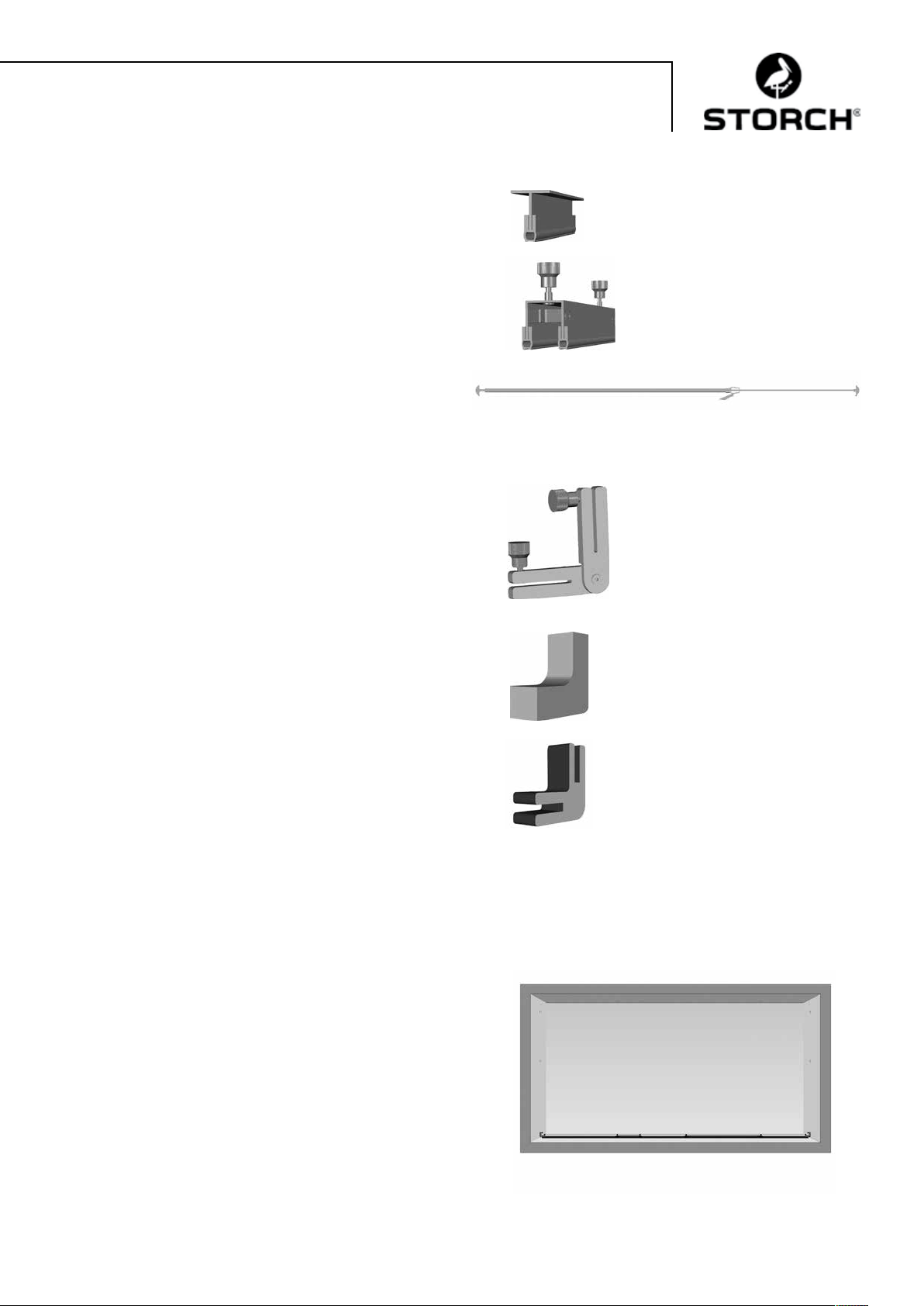
Les différents éléments du Cover Quick® Wall et leur mode de fonctionnement
Profilé d'assemblage T (25, 100, 150 cm)
Á monter généralement sur les extrémités des constructions créées pour un montage ultérieur des raccords
d'angle.
Profilé intermédiaire en U (50, 100, 150 cm)
Élément de construction dans lequel les profilés d'assemblage T sont insérés de part et d'autre et fixés à l'aide de
vis de blocage.
Support téléscopique (déployable sur max. 380 cm)
Pour fixer la construction et garantir l'étanchéité en
exerçant une pression sur les constructions des murs, des
sols et des plafonds.
Raccords d'angle
Pour assembler les constructions des sols et des plafonds
avec les constructions latérales
Pour monter les constructions latérales ou de sols et/ou
de plafonds coudées
Montage exclusivement à l'extérieur des profilés d'assemblage T
Joint d'angle 70 x 70 mm
Pour un serrage entre le sol et/ou les plafonds et les murs
et les raccords d'angle du Cover Quick Wall
étanchéité et d'une protection supplémentaire des surfaces
Joint d'angle 80 x 80 mm
Pour un montage dans les assemblages de sols et de plafonds perpendiculaires (solution d'angle et double solution d'angle) en dessous des raccords d'angle en vue de
l'étanchéité de la construction
®
en vue d'une
Montage d'une séparation intérieure Cover Quick® Wall
a) Détermination de la zone à séparer
Á cet effet, il convient de poser les profilés T et U en alternance sur le sol, de les assembler et de déployer sur la longueur souhaitée.
b) Assemblage des éléments de sol et de plafond
Éléments nécessaires pour une largeur de montage jusqu'à 5,30 m :
1 x profilé d'assemblage T 150
2 x profilés d'assemblage T 100
1 x profilé intermédiaire en U 150 cm
1 x profilé intermédiaire en U 50
Veiller à ce qu'un profilé T sur lequel vous fixez un raccord d'angle à l'extérieur du profilé soit placé sur les deux
extrémités.
Écarter la construction de sorte que les raccords d'angle
soient le plus près possible des murs. Serrer à la main les
vis de fixation.
25
Page 26
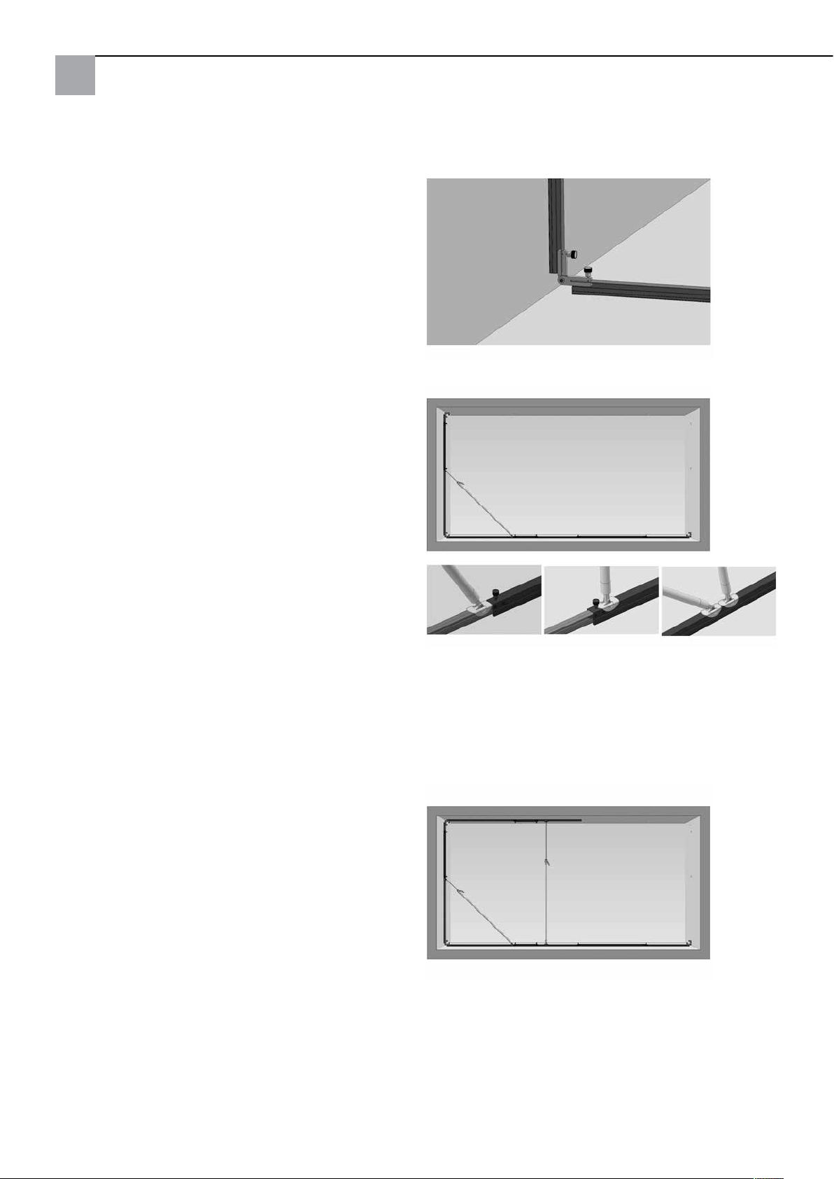
Assemblage du profilé T avec le raccord d'angle
c) Assemblage des éléments latéraux
Éléments nécessaires pour une hauteur de plafond jusqu'à
2,70 m :
1 x profilé d'assemblage T 150
1 x profilé intermédiaire en U 100
1 x profilé d'assemblage T 25
Pour le montage des éléments latéraux, assembler les
profilés T et U de sorte qu'un profilé T soit placé sur les
deux extrémités. Fixer un raccord d'angle au niveau de
l'extrémité supérieure des éléments latéraux sur le côté
extérieur. Relier l'élément latéral se trouvant en bas avec
le raccord d'angle de l'élément de sol, écarter à la hauteur
souhaitée, puis serrer les vis de fixation à la main.
d) Protection des éléments latéraux avec les supports
téléscopiques
Pour protéger l'élément latéral, placez un support téléscopique en diagonale entre l'élément de sol et l'élément
latéral.
Á cet effet, placer le support téléscopique avec les plateaux d'appui sur les parties supérieures des profilés des
éléments de mur et de sol, déployer le tube intérieur en
desserrant et en réenclenchant ultérieurement les ergots
d'arrêt sur la longueur adaptée.
Pour une fixation et un réglage précis de la longueur des
supports téléscopiques, actionner ensuite à plusieurs
reprises la poignée de serrage jusqu'à ce que les plateaux
d'appui ou les vis de fixation des profilés soient arrêtés
par les bords des transitions des profilés T aux profilés U
ou au niveau des pieds d'appui des supports montés verticalement. Exercez uniquement la pression nécessaire
pour garantir l'étanchéité des éléments muraux.
Remarque :
Pour positionner le support : veiller à ce que les poignées
de serrage des supports téléscopiques soient positionnées
vers l'extérieur. Ainsi, les poignées ne gênent pas lors du
décollage des profilés sur la partie intérieure.
e) Montage de l'élément mural
Assembler l'élément de plafond dans la même longueur
que l'élément du sol (sans raccord d'angle) avec les profilés T au niveau des deux extrémités.
Assembler d'abord un profilé T et un profilé U pour env.
la moitié de la distance du plafond.
Assembler ensuite l'élément T de cette section de la
construction du plafond avec le raccord d'angle de l'élément latéral et le laisser suspendre en flottant sur l'élément latéral.
Stabiliser ensuite cette section flottante au moyen du
support téléscopique que vous placez et déployez entre la
construction du plafond et la construction du sol.
26
Page 27
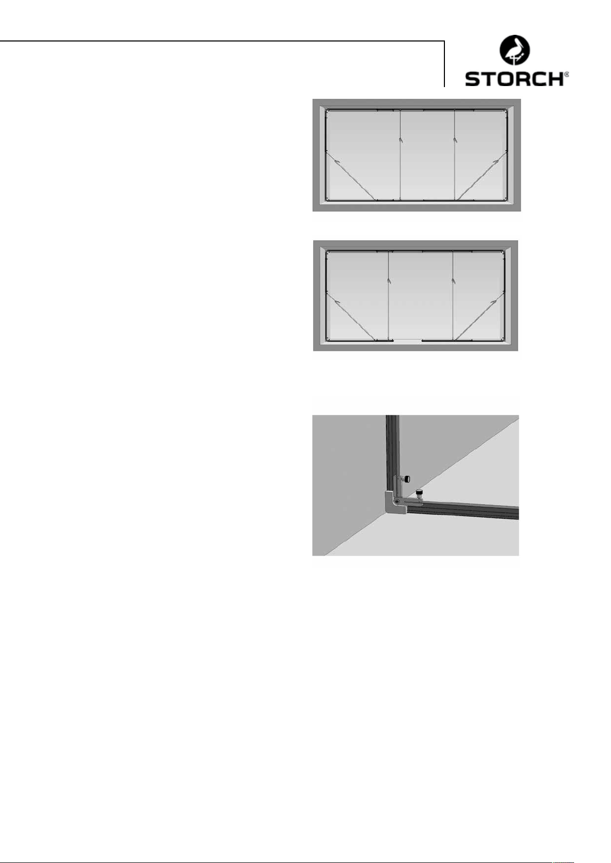
Les éléments des profilés de la pièce centrale de la
construction du plafond sont, autant que possible, introduits dans celle-ci après le montage de la première pièce
centrale.
Sur le côté opposé, procéder de la même manière qu'il
est décrit dans le point c. à e. lors du montage de l'élément latéral et du reste de l'élément du plafond.
Retirer ensuite la pièce centrale de la première section
latérale de l'élément de plafond, déjà montée, l'assembler avec la section opposée et serrer les vis de fixation.
Remarque :
Si vous devez pénétrer dans la zone séparée, vous pouvez
également retirer une pièce profilée de l'élément du sol.
f) Réglage précis et protection
Insérer les joints d'angle (70 x 70) à l'extérieur des quatre
angles en haut et en bas de sorte qu'ils soient le moins
proéminents possible sur le côté qui est collé ultérieurement avec le film CQ et positionnés de façon plane par
rapport à la surface du profilé.
Pour un placement optimal des joints d'angle et pour le
réglage précis du Cover Quick Wall
®
, les aligner en desserrant légèrement les raccords à vis entre les profilés
et en retirant ou insérant les profilés sur la longueur
adaptée.
Contrôler l'appui uniforme des joints des profilés U et T
sur les surfaces des murs, des plafonds ou du sol. Si les
joints des profilés ne sont pas au niveau des surfaces,
déplacer l'un des supports de sorte que la pression soit
répartie uniformément et que l'étanchéité soit garantie.
Serrer ensuite toutes les vis de fixation pour une tenue
stable et contrôler l'ajustement sûr des supports téléscopiques.
27
Page 28
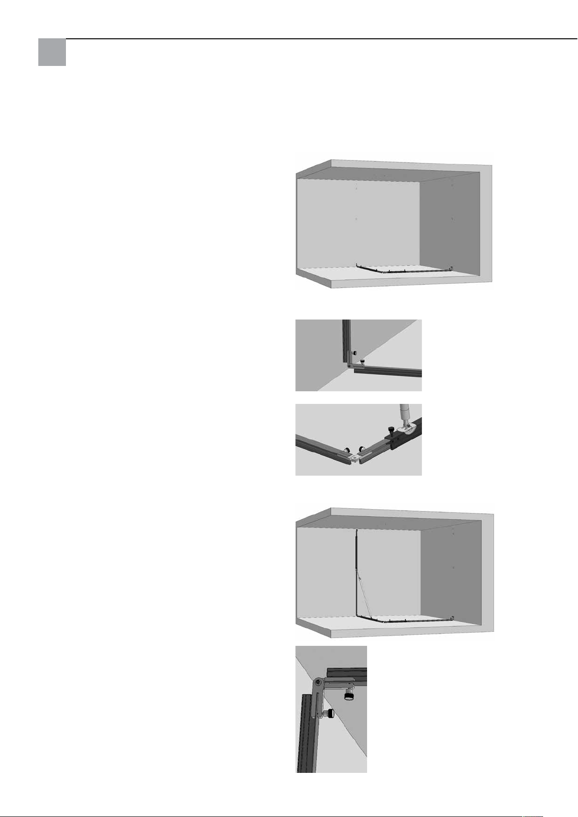
Montage d'une séparation d'angle Cover Quick® Wall
a) Détermination de la zone à séparer
Á cet effet, il convient d'assembler les profilés U et T nécessaires, de les poser sur le sol dans l'angle droit et de déployer sur la longueur souhaitée.
b) Assemblage des éléments de sol et de plafond
Éléments nécessaires pour maximum 2,70 m de haut,
3,40 m de large et 2,15 m de profondeur
Page 1 :
2 x profilés d'assemblage T 100
1 x profilé intermédiaire en U 150
Page 2 :
1 x profilé d'assemblage T 25
1 x profilé d'assemblage T 150
1 x profilé intermédiaire en U 50
Un profilé T doit être placé sur les deux extrémités du
côté de la construction du sol.
Fixer un raccord d'angle sur la partie supérieure du profilé
T dans les deux sections extérieures de la construction du
sol, dirigées vers les murs. Les éléments latéraux sont
ainsi assemblés ultérieurement.
Assembler ensuite les deux côtés de la construction du
sol, situés dans l'angle droit, avec un raccord d'angle que
vous fixez au-dessus des lèvres d'étanchéité au niveau
des profilés T à l'aide de vis de blocage.
Écarter ensuite la construction du sol de sorte que les raccords d'angle soient le plus près possible des murs, puis
serrer tous les vis de blocage à la main.
c) Montage et fixation des éléments latéraux
Le montage suivant et la fixation des éléments latéraux
au moyen des supports téléscopiques s'effectuent tel qu'il
est décrit dans le point « Montage d'une séparation intérieure Cover Quick Wall
®
» c).
Veiller à apposer sur l'extrémité supérieure de la
construction latérale un raccord d'angle que vous assemblez avec la construction du plafond de la manière suivante.
28
Page 29
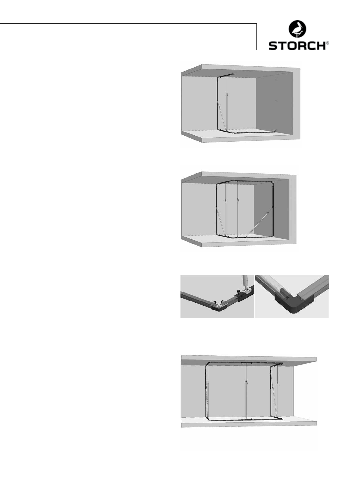
d) Montage et fixation des éléments de plafond
Assembler les deux côtés de la construction du plafond
dans la même longueur que celle de la construction du
sol avec les profilés T sur les deux extrémités. Les fixer à
la main à l'aide de vis de blocage.
Assembler le profilé d'assemblage T extérieur du premier
côté de la construction du plafond avec le raccord d'angle
de l'élément latéral, puis stabiliser cette section flottante
au moyen du support téléscopique que vous placez et
déployez entre la construction du plafond et la construction du sol.
Procéder de la même manière sur le côté opposé avec
l'élément latéral et l'élément de plafond.
Assembler ensuite les deux côtés de la construction du
plafond avec un raccord d'angle que vous fixez au-dessous des lèvres d'étanchéité au niveau du profilé T à
l'aide de vis de blocage.
e) Réglage précis et protection
Á cet effet, il convient de procéder conformément au
point f du « Montage de la séparation murale Cover Quick
®
».
Wall
Insérer également deux joints de sol / plafond 80 x 80
dans les profilés T au niveau des points d'assemblage perpendiculaires de la construction de sol et de plafond en dessous des raccords d'angle en recouvrant le
joint d'angle 80 x 80 avec les fentes prévues à cet effet
au-dessus des profilés T.
Montage du Cover Quick® en U
Á cet effet, le kit d'extension Cover Quick Wall® (réf. art.
56 55 10) est nécessaire en plus du kit de base.
Pour le montage, il convient de se baser sur le montage
d'une solution d'angle. L'ordre de montage est identique
et correspond à une solution d'angle double.
29
Page 30

Recouvrement des constructions Cover Quick® Wall
L'utilisation de Cover Quick® et de ruban de masquage est recommandée. Appliquer le ruban de masquage sur les profilés muraux et de sol côté chantier.
Coller Cover Quick® sur la partie intérieure du chantier sur les constructions de plafond, déplier et fixer sur le côté à
l'aide du ruban de masquage ou de réparation. Il est aussi possible de recouvrir à l'aide d'un film plastique.
Remarque :
Suite au recouvrement sur la partie intérieure de la construction, éviter l'encrassement direct des éléments du Cover
Quick® Wall.
Utilisation de la porte souple
La porte souple avec fermeture zippée permet un accès à la zone de travail que l'on peut refermer : décoller d'abord un
cadre de porte adapté à l'aide du ruban de masquage sur le film. Y coller la porte souple et en supprimer le surplus à
l'aide d'un cutter ou de ciseaux.
30
Page 31
Garantie
Conditions de garantie
Les durées de garantie légales de 12 mois à compter de la date d'achat / de la facture du client final professionnels
s'appliquent à nos appareils. Si nous mentionnons des délais supérieurs dans le cadre d'une déclaration de garantie,
ceux-ci sont mentionnés dans les instructions de service des appareils concernés.
Exercice
Dans un cas couvert par la garantie, nous vous demandons de renvoyer l'appareil complet franco à notre centre
logistique à Berka accompagné de la facture ou de l'expédier à une station SAV agréée par nous.
Veuillez contacter préalablement l‘assistance téléphonique payante de la société STORCH: +49 (0)202 . 49 20 – 110.
Demande de prise en garantie
Les demandes couvrent exclusivement les défauts de matériau ou d‘ouvrage et ne couvrent qu‘une utilisation conforme
à la destination de l‘appareil. Les pièces d‘usure ne sont pas prises en charge par la garantie. Tout droit à garantie est
rendu caduque par le montage de pièces qui ne sont pas d‘origine, par une manipulation et un entreposage incorrects
ainsi qu‘en cas de non-respect évident des instructions de service.
Exécution de réparations
Toutes les réparations doivent exclusivement être réalisées par notre usine ou par des services SAV agréés par
STORCH.
31
Page 32
IT
Grazie
per la fiducia accordata a STORCH. Con l‘acquisto avete scelto un prodotto di qualità.
Se comunque avete dei suggerimenti volti a migliorare la nostra offerta o se doveste incontrare
qualche difficoltà, non esitate a rivolgerVi a noi.
Contattate il Vostro rappresentante oppure rivolgeteVi direttamente a noi in casi urgenti.
Distinti saluti,
STORCH Reparto Assistenza
Tel.: 02 - 66 22 77 15
Indice Pagina
Dotazione di fornitura set di base Cover Quick® Wall 32
®
Dotazione di fornitura set di ampliamento Cover Quick
Avvertenze di utilizzo e di cura del sistema Cover Quick
Varianti di montaggio con il set di base Cover Quick
Varianti di montaggio con il set di ampliamento Cover Quick
®
I singoli elementi del sistema Cover Quick
Wall e loro funzione 35
Realizzazione di una separazione all'interno di un locale con Cover Quick
Realizzazione di una struttura ad angolo con Cover Quick
Realizzazione di una struttura ad U con Cover Quick
Copertura delle strutture realizzate con Cover Quick
Montaggio della porta protettiva in film plastico 40
Garanzia 41
Wall 33
®
Wall 33
®
Wall 34
®
Wall 34
®
Wall 35 - 37
®
Wall 38 - 39
®
Wall 39
®
Wall 40
Dotazione di fornitura set di base Cover Quick® Wall (N. art. 56 55 00)
Nella tabella i numeri articolo per ricambi e materiali di consumo per ordinazioni supplementari.
Numero Descrizione N. art.
4 Supporto telescopico CQ-Wall 56 55 20
1 Manico da trasporto per supporti telescopici 56 55 25
1 Borsa da trasporto 56 50 50
4 Profilo di collegamento a T 150 cm 56 55 17
4 Profilo di collegamento a T 100 cm 56 55 18
4 Profilo di collegamento a T 25 cm 56 55 19
2 Profilo intermedio a U 150 cm 56 55 14
2 Profilo intermedio a U 100 cm 56 55 15
2 Profilo intermedio a U 50 cm 56 55 16
6 Raccordo angolare 56 55 13
4 Guarnizione angolare 70 x 70 mm 56 55 11
2 Guarnizione per pavimento / soffitto 80 x 80 mm 56 55 12
1 Rotolo di nastro maschera 25 mm x 25 m 49 57 25
1 Rotolo di nastro di riparazione 48 mm x 50 m argento per il fissaggio della porta pro-
tettiva in film plastico
1 Film plastico CQ con nastro in tessuto 270 cm x 20 m K 20 cm 48 98 43
1 Porta protettiva in film plastico con chiusura a strappo 49 91 30
49 07 50
32
Page 33
Dotazione di fornitura set di ampliamento Cover Quick® Wall (N. art. 56 55 10)
Numero Descrizione N. art.
1 Supporto telescopico CQ-Wall 56 55 20
2 Profilo di collegamento a T 150 cm 56 55 17
2 Profilo di collegamento a T 25 cm 56 55 19
2 Profilo intermedio a U 150 cm 56 55 14
2 Raccordo angolare 56 55 13
2 Guarnizione per pavimento / soffitto 80 x 80 mm 56 55 12
Avvertenze di utilizzo e di cura del sistema Cover Quick® Wall
Sincerarsi sempre che gli elementi assemblati siano stati fissati in sicurezza e / o saldamente montati! Pericolo di
caduta per componenti laschi e / o non saldamente montati.
Prestare attenzione in caso di soffitti sospesi! In determinate circostanze non è possibile montare il sistema, in quanto i
profili per il soffitto non possono essere montati in maniera stabile, oppure detti profili, insieme alla pressione esercitata dai sostegni telescopici, possono danneggiare la struttura del soffitto.
Prima di montare il sistema verificare le condizioni e la sensibilità delle superfici (pareti, pavimento e soffitto)! Nonostante le guarnizioni in gomma siamo morbide ed incolori, si declina qualsiasi responsabilità per eventuali danni alle
superfici. Per maggior sicurezza effettuare una piccola prova su di un punto nascosto per verificare la reazione alla
compressione delle guarnizioni in gomma, utilizzando un profilo qualsiasi e appoggiando il lato con la guarnizione sulla
superficie, esercitando una leggera pressione e sfregandolo contro la superficie.
In caso di forti dislivelli delle superfici, o se sono presenti componenti installati come cavi, tubazioni per il riscaldamento o simili, in alcuni casi non è possibile compensare detti dislivelli con i profili, per cui il sistema anti-polvere non può
essere installato a tenuta.
Sincerarsi sempre che tutti i componenti e gli elementi di assemblaggio non siano danneggiati e siano regolarmente
funzionanti. Se uno degli elementi non funziona o viene smarrito, esso può essere sempre ordinato successivamente
indicando il relativo n. art.
Pulire i profili insieme alle guarnizioni dopo ciascun utilizzo con un panno umido. In questo modo si garantisce un incollaggio sicuro dei nastri adesivi sulla superficie del profilo, evitando di sporcare le superfici delle pareti, del soffitto e del
pavimento durante il montaggio.
Pulire anche i supporti telescopici e le relative piastre di appoggio per garantire sempre un sostegno costante. Evitare
il contatto del dispositivo di serraggio con lubrificanti di vario tipo in corrispondenza della leva di serraggio. In caso contrario la forza di serraggio può ridursi.
33
Page 34
Versioni di montaggio con il set di base Cover Quick® Wall (N. art. 56 55 00)
a) Separazione all'interno di un locale
Dim. max.: altezza 2,70 m e larghezza 5,30 m Dim. max.: altezza 3,80 m x larghezza 4,00 m
b) Struttura ad angolo
Dimensioni max.: altezza 2,70 m, larghezza 3,40 m e
profondità 2,15 m
Le dimensioni delle separazioni possono essere adattate
in continuo a piacere.
Versioni di montaggio con il set di ampliamento Cover Quick® Wall (N. art. 56 55 10)
Il set di ampliamento permette di ottenere ulteriori versioni di montaggio e di ingrandire le versioni di montaggio disponibili:
a) Ampliamento della separazione all'interno di un
locale
Per ciascun set di ampliamento è possibile ampliare
ogni volta la separazione all'interno di un locale di
2,80 m
b) Soluzioni ad angolo da entrambi i lati
(forma a U)
Dimensioni max.: altezza 2,70 m x
profondità 2,65 m x larghezza 3,40 m
34
Page 35
I singoli elementi del sistema Cover Quick® Wall e loro funzione
Profilo di collegamento a T (25, 100, 150 cm)
Da montare in linea di massima alle estremità delle strutture create per il montaggio successivo dei raccordi angolari.
Profilo intermedio a U (50, 100, 150 cm)
Elemento costruttivo nel quale i profili di collegamento a
T vengono inseriti su entrambi i lati e fissati con le viti di
bloccaggio.
Supporto telescopico (estraibile fino a max. 380 cm)
Per il fissaggio della struttura e a garanzia di tenuta se si
esercita una certa pressione sulla struttura della parete,
del pavimento e del soffitto.
Raccordo angolare
Per il collegamento delle strutture del pavimento e del
soffitto alle strutture laterali
Per il montaggio delle strutture angolate laterali, del
pavimento e del soffitto
Montaggio esclusivamente all'esterno sui profili di collegamento a T
Guarnizione angolare 70 x 70 mm
Per incastrare il Cover Quick Wall
soffitto e le pareti, per impermeabilizzare e proteggere le
superfici
Guarnizione angolare 80 x 80 mm
Da montare nei collegamenti perpendicolari per il pavimento ed il soffitto (soluzione ad angolo e doppia soluzione ad angolo), al di sotto dei raccordi angolari per impermeabilizzare la struttura
®
tra il pavimento o il
Realizzazione di una separazione all'interno di un locale con Cover Quick® Wall
a) Determinazione della zona da separare
A tal fine disporre alternati i profili a T e a U sul pavimento, unirli ed estrarli alla lunghezza desiderata.
b) Assemblaggio degli elementi per pavimento e soffitto
Elementi necessari per una struttura di larghezza max.
5,30 m:
1 profilo di collegamento a T 150
2 profili di collegamento a T 100
1 profilo intermedio a U 150,
1 profilo intermedio a U 50
Prestare attenzione a che alle due estremità sia collocato
ogni volta un profilo a T, all'esterno del quale occorrerà
poi fissare un raccordo angolare.
Realizzare la struttura in modo tale da collocare i raccordi
angolari il più vicino possibile alle pareti. Dopodiché serrare a mano le viti di fissaggio.
35
Page 36
Collegamento profilo a T - raccordo angolare
c) Assemblaggio degli elementi laterali
Elementi necessari per un soffitto di altezza max. 2,70 m:
1 profilo di collegamento a T 150
1 profilo intermedio a U 100
1 profilo di collegamento a T 25
Per la realizzazione degli elementi laterali, collegare
i profili a T e a U in modo tale da collocare ogni volta
un profilo a T su entrambe le estremità. Sull'estremità
superiore degli elementi laterali fissare ogni volta sul lato
esterno un raccordo angolare. Collegare l'elemento laterale in basso al raccordo angolare dell'elemento per il
pavimento, allungarlo fino ad ottenere l'altezza desiderata e serrare infine a mano le viti di fissaggio.
d) Consolidamento degli elementi laterali con i supporti
telescopici
Per il consolidamento degli elementi laterali collocare un
supporto telescopico in obliquo tra l'elemento per il pavimento e quello laterale.
A tal fine collocare il supporto telescopico con le piastre
di supporto sui lati superiori dei profili degli elementi per
le pareti e il pavimento, estrarre il tubo interno allentando
e facendo poi scattare nuovamente in posizione i naselli
di bloccaggio alla lunghezza idonea.
Per il fissaggio e l'aggiustamento di precisione della lunghezza dei supporti telescopici azionare quindi più volte
la relativa maniglia fino a che le piastre di supporto non
vengono bloccate dalle viti di fissaggio dei profili per
effetto dei bordi dei passaggi dai profili a T a quelli a U,
o in corrispondenza dei piedini di supporto dei supporti
telescopici montati perpendicolarmente. Esercitare solamente la pressione sufficiente a garantire la tenuta degli
elementi per le pareti.
Avvertenza:
per posizionare il supporto: prestare attenzione a che le
maniglie dei supporti telescopici siano posizionate verso l'esterno. In questo modo le maniglie non intralciano
durante la sigillatura dei profili sul lato interno.
e) Realizzazione dell'elemento per il soffitto
Predisporre l'elemento per il soffitto della stessa lunghezza dell'elemento per il pavimento (senza raccordi angolari), con i profili a T su entrambe le estremità.
Prima di tutto collegare tra loro un profilo a T e un profilo
a U per circa la metà della distanza dal soffitto.
Dopodiché collegare l'elemento a T di questa parte di
struttura del soffitto al raccordo angolare dell'elemento
laterale, e lasciarlo pendere sull'elemento laterale.
Infine stabilizzare questa parte pendente con il supporto
telescopico collocato ed estratto tra la struttura del soffitto e quella del pavimento.
36
Page 37
Dopo aver montato la prima parte, inserire in questa
quanto più possibile gli elementi profilati della parte centrale della struttura per il soffitto.
Sul lato opposto procedere analogamente al montaggio
della parte laterale e al resto dell'elemento per il soffitto
come descritto ai punti da c. a e.
Al termine estrarre la parte centrale dalla prima parte
laterale già montata dell'elemento per il soffitto, collegarla alla parte opposta e serrare le viti di fissaggio.
Avvertenza:
se si rivela necessario accedere alla zona separata, è
anche possibile rimuovere un elemento profilato dall'elemento per il pavimento.
f) Aggiustamento di precisione e consolidamento
Incastrare le guarnizioni angolari (70 x 70) all'esterno, in
corrispondenza dei quattro angoli, in alto e in basso, in
modo da non creare sporgenze sul lato che sarà successivamente incollato con il film plastico CQ, e in modo che
queste siano trasversali rispetto alla superficie del profilo.
Per il posizionamento ottimale delle guarnizioni angolari e per l'aggiustamento di precisione del sistema
Cover Quick Wall
®
, orientarle allentando leggermente le
connessioni a vite tra i profili, ed estraendo o inserendo
questi ultimi alla lunghezza adatta.
Verificare l'appoggio uniforme delle guarnizioni dei profili
a U e a T sulle superfici delle pareti, del soffitto o del
pavimento. Se le guarnizioni dei profili non chiudono
a filo le superfici, spostare uno dei supporti in modo da
distribuire uniformemente la pressione e garantire così la
tenuta.
Serrare infine tutte le viti di fissaggio per una corretta
stabilità, e verificare l'alloggiamento sicuro dei sostegni
telescopici.
37
Page 38
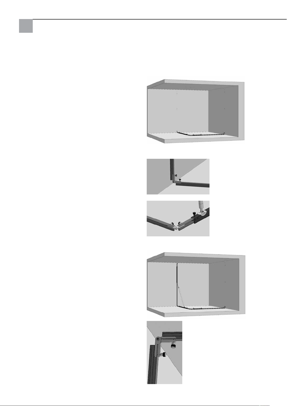
Realizzazione di una struttura ad angolo con Cover Quick® Wall
a) Determinazione della zona da separare
A tal fine unire i profili a U e a T necessari, posarli ad angolo retto uno rispetto all'altro sul pavimento ed estrarli alla
lunghezza desiderata.
b) Assemblaggio degli elementi per pavimento e soffitto
Elementi necessari per una struttura di dimensioni max.:
altezza 2,70 m, larghezza 3,40 m e profondità 2,15 m
Lato 1:
2 profili di collegamento a T 100
1 profilo intermedio a U 150
Lato 2:
1 profilo di collegamento a T 25
1 profilo di collegamento a T 150
1 profilo intermedio a U 50
Collocare ogni volta un profilo a T su entrambe le estremità del fianco della struttura per il pavimento.
In corrispondenza delle due parti esterne della struttura per il pavimento, rivolte verso le pareti, fissare per
ognuna di esse un raccordo angolare sul lato superiore del
profilo a T. A detti raccordi saranno poi collegati gli elementi laterali.
Dopodiché collegare ad angolo retto, uno rispetto
all'altro, i due fianchi della struttura del pavimento ad
un raccordo angolare, e fissare quest'ultimo con le viti
di bloccaggio al di sopra dei labbri di tenuta in corrispondenza dei profili a T.
Allargare poi la struttura per il pavimento in modo che
i raccordi angolari appoggino il più possibile alle pareti,
infine serrare a mano le viti di bloccaggio.
c) Realizzazione e fissaggio degli elementi laterali
La realizzazione e il fissaggio descritti qui di seguito degli
elementi laterali mediante i sostegni telescopici avviene
come descritto al punto c) "Realizzazione di una separazione all'interno di un locale con Cover Quick
®
Wall".
Prestare attenzione ad applicare un raccordo angolare in
corrispondenza dell'estremità superiore della struttura
laterale, da collegare poi alla struttura del soffitto.
38
Page 39
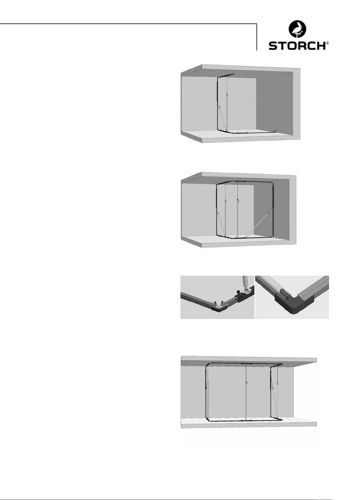
d) Realizzazione e fissaggio degli elementi per il soffitto
Disporre i due fianchi della struttura per il soffitto della stessa lunghezza della struttura per il pavimento, con
i profili a T su entrambe le estremità. Fissare poi questi
ultimi a mano con le viti di bloccaggio.
Dopodiché collegare il profilo di collegamento a T esterno
del primo fianco della struttura per il soffitto al raccordo
angolare dell'elemento laterale, e stabilizzare infine la
parte pendente con un sostegno telescopico, collocato ed
estratto tra la struttura per il soffitto e quella per il pavimento.
Procedere analogamente sul lato opposto con l'elemento
laterale e quello per il soffitto.
Collegare infine i due fianchi della struttura per il soffitto
con un raccordo angolare, fissato sul profilo a T al di sotto
dei labbri di tenuta con le viti di bloccaggio.
e) Aggiustamento di precisione e consolidamento
Procedere a tal fine come descritto al punto f di "Realizzazione della separazione di una parete con Cover Quick
®
".
Wall
Incastrare inoltre due guarnizioni per il pavimento / per
il soffitto 80 x 80 nei profili a T, in corrispondenza dei
punti di raccordo perpendicolari della struttura per il
pavimento e di quella del soffitto, al di sotto dei raccordi angolari, sistemando la guarnizione angolare 80 x 80
con le apposite fessure sopra i profili a T.
Realizzazione di una struttura ad U con Cover
Quick® Wall
A tal fine è necessario, oltre al set di base, il set di ampliamento Cover Quick Wall® (N. art. 56 55 10).
Per la realizzazione orientarsi sulla realizzazione di una
soluzione ad angolo. La sequenza di montaggio è identica
e corrisponde ad una doppia soluzione ad angolo.
39
Page 40

Copertura delle strutture realizzate con Cover Quick® Wall
Si consiglia l'impiego di Cover Quick® e nastro maschera. Incollare sui profili per parete e per pavimento sul lato cantiere il nastro maschera.
Incollare Cover Quick® sulle strutture per il soffitto sul lato interno del cantiere, dispiegarlo e fissarlo di lato con il
nastro maschera o il nastro di riparazione. In alternativa si può coprire anche con film plastico.
Avvertenza:
con la copertura sul lato interno della struttura, evitare di sporcare direttamente gli elementi del sistema Cover Quick®
Wall.
Impiego della porta protettiva in film plastico
L'utilizzo della porta protettiva in film plastico con chiusura a strappo consente di ottenere un accesso richiudibile
all'area di lavoro: sigillare un telaio porta adatto con il nastro maschera sul film plastico. Incollare poi la porta protettiva
in film plastico e rimuovere il film plastico in eccesso con un taglierino o con le forbici.
40
Page 41
Garanzia
Condizioni di garanzia:
Per i nostri apparecchi sono applicabili dei periodi di garanzia di 12 mesi a partire dalla data di acquisto / data della
fattura del cliente finale commerciale. Se da parte nostra vengono accordati dei periodi di garanzia più estesi, ciò sarà
riportato separatamente nelle istruzioni per l'uso inerenti ai rispettivi dispositivi.
Rivendicazioni:
In casi in cui si intende far valere il diritto di garanzia, vi preghiamo di inviarci il dispositivo in modo completo con fattura, franco nostro centro di logistica a Berka oppure ad una service-station da noi autorizzata.
Si prega di consultare prima la Hotline di servizio STORCH a pagamento: 02 - 66 22 77 15
Diritto alla garanzia
Il diritti si possono far valere solo per errori di materiale o di produzione nonché esclusivamente in caso di utilizzo
appropriato del dispositivo. Pezzi soggetti all‘usura non sono soggetti a diritti di garanzia. Decadranno tutti i diritti di
garanzia con l‘aggiunta delle componenti di terzi, maneggio e magazzinaggio non appropriato come anche in casi di
ovvia non osservanza delle istruzioni per l‘uso.
Esecuzione di riparazioni
Ogni intervento di riparazione va eseguito esclusivamente nei nostri stabilimenti o presso una service-station autorizzata STORCH.
41
Page 42
GB
Thank you
for purchasing a STORCH product. You have purchased a quality product.
If you would like to suggest an improvement, or experience a problem with your product, please do not hesitate to contact us.
Please contact your field sales representative or, in urgent cases, contact us directly.
Yours sincerely,
STORCH Service Department
Tel.: +49 (0)2 02 . 49 20 - 112
Fax: +49 (0)2 02 . 49 20 - 244
Free service hotline: 0800 786 72 47
Toll-free order hotline: +49 800 7867244
Toll-free order fax: +49 800 7867243
(only available in Germany)
Table of contents Page
Cover Quick® Wall Basic Set - scope of delivery 42
®
Cover Quick
Guidance for use and maintenance of the Cover Quick
Installation variants with the Cover Quick
Installation variants with the Cover Quick
Individual elements of the Cover Quick
Installation of a Cover Quick
Installation of a Cover Quick
Installation of a Cover Quick
Covering of Cover Quick
Use of the sheeting door 50
Warranty 51
Wall Extension Set - scope of delivery 43
®
Wall 43
®
Wall Basic Set 444
®
Wall Extension Set 4
®
Wall and their function 45
®
Wall room separator 45 - 47
®
Wall corner separator 48 - 49
®
Wall in U shape 49
®
Wall structures 50
Cover Quick® Wall Basic Set - scope of delivery (art. no. 56 55 00)
The table shows item numbers of spare parts and consumables for repeat orders.
Quantity Designation Code number
4 CQ Wall telescopic supports 56 55 20
1 Transport and carry handle for telescopic supports 56 55 25
1 Carrying bag 56 50 50
4 T connection profile 150 cm 56 55 17
4 T connection profile 100 cm 56 55 18
4 T connection profile 25 cm 56 55 19
2 U intermediate profile 150 cm 56 55 14
2 U intermediate profile 100 cm 56 55 15
2 U intermediate profile 50 cm 56 55 16
6 Corner connector 56 55 13
4 Corner seal 70x70 mm 56 55 11
2 Floor / ceiling seal 80 x 80 mm 56 55 12
1 Masking tape roll 25 mm x 25 m 49 57 25
1 Repair tape roll 48 mm x 50 m silver for attaching the sheeting door 49 07 50
1 CQ sheeting with fabric tape 270 cm x 20 m x 20 cm 48 98 43
1 Sheeting door with a zipper 49 91 30
42
Page 43
Cover Quick® Wall Extension Set - scope of delivery (art. no. 56 55 10)
Quantity Designation Code number
1 CQ Wall telescopic support 56 55 20
2 T connection profile 150 cm 56 55 17
2 T connection profile 25 cm 56 55 19
2 U intermediate profile 150 cm 56 55 14
2 Corner connector 56 55 13
2 Floor / ceiling seal 80 x 80 mm 56 55 12
Guidance for use and maintenance of the Cover Quick® Wall
Always make sure that the assembled elements are always securely set aside and / or fixed! Loose and / or not fixed
elements may cause a risk of collapse.
Caution with suspended ceilings! Installation may not be possible because the ceiling profiles and the pressure exerted
by the telescopic supports can damage the ceiling structure and / or not may not be installed in a stable enough way.
Before installation please check the properties and the sensitivity of the surfaces (walls, floor and ceiling)! Despite the
soft and colourless rubber seals we assume no liability for any surface damages. For good measure please check the
reaction to the pressure of the rubber seals on an invisible spot by placing a profile with the seal side on the surface,
applying some pressure and rubbing over the surface.
If the surfaces or the mounting parts installed there, such as cables, heating pipes etc. are very uneven, it may happen
that the unevenness is too great and that the dust cover system cannot be installed with appropriate tightness.
Always make sure that all parts and mounting elements are not damaged and work perfectly. If one of the elements is
broken or lost, you can re-order it using the article number provided above.
Clean the profiles including seals after each use with a damp cloth. Thus you ensure secure adhesion of the adhesive
tapes on the profile surface and avoid any soiling of the wall, ceiling and floor surfaces during installation.
Also make sure to clean the telescopic supports and their supporting plates in order to ensure a secure fit at all times.
Avoid contact of lubricants of any kind with the clamping device on the clamping lever. This way the clamping force
might be reduced.
43
Page 44
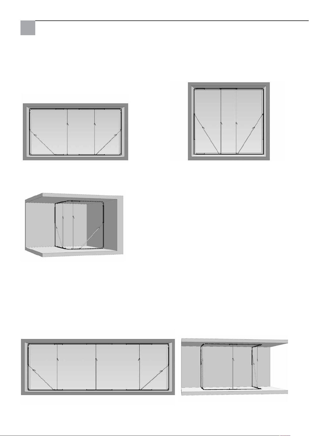
Installation variants with the Cover Quick® Wall Basic Set (art. no. 56 55 00)
a) Room separators
Max. height 2,70 m and width 5,30 m Max. height 3,80 m x width 4,00 m
b) Corner separator
Max. height 2,70 m, width 3,40 m, and depth 2,15 m
You may steplessly customize the separator dimensions
as needed.
Installation variants with the Cover Quick® Wall Extension Set (art. no. 56 55 10)
The extension set allows for additional installation variants and the enlargement of the aforementioned installation
variants:
a) Extension of room separators
With each extension set you extend the room separators by 2,80 m at a time
b) Two-sided corner solutions (U shape)
Max. height 2,70 m, depth 2,65 m and
width 3,40 m
44
Page 45
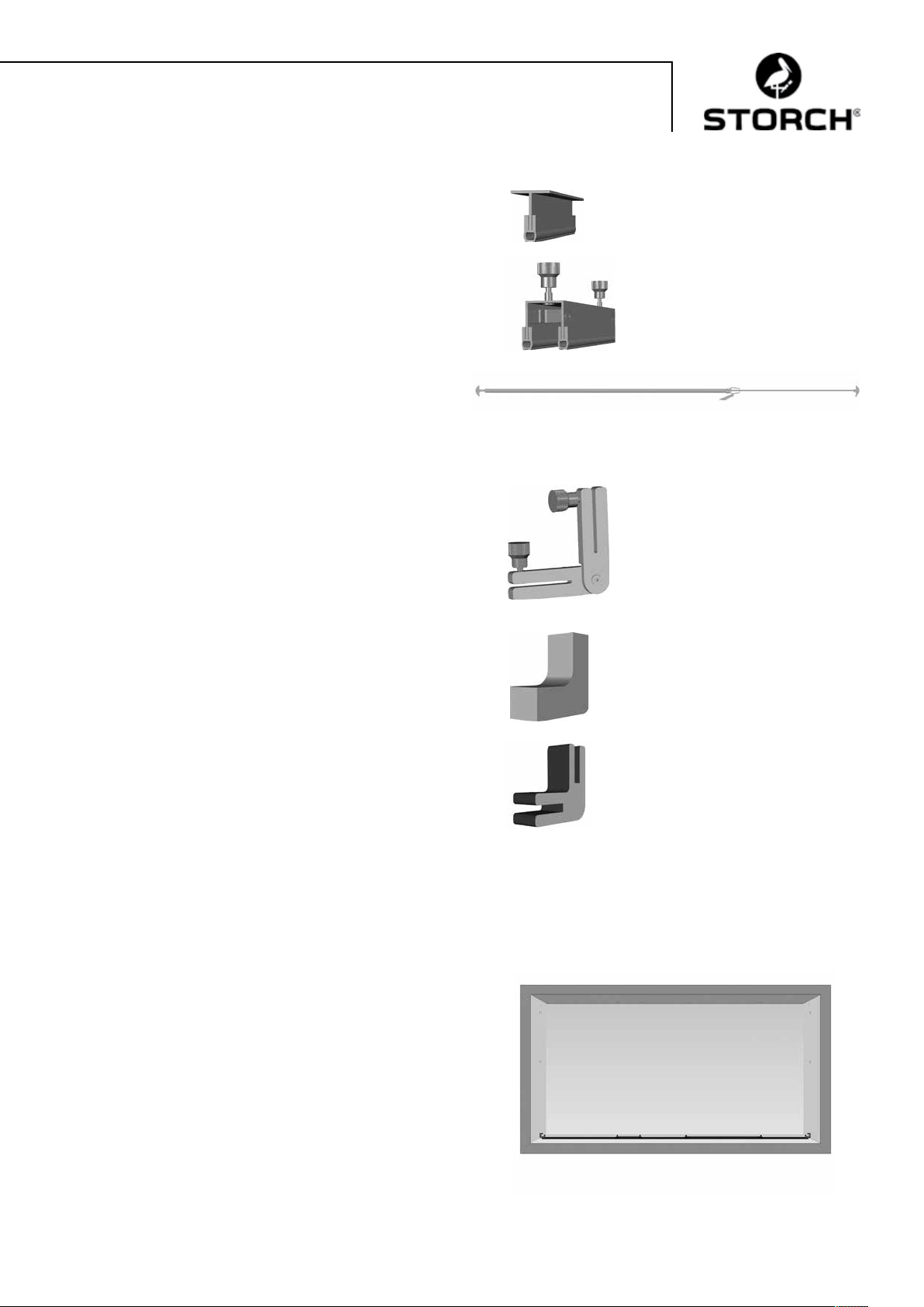
Individual elements of the Cover Quick® Wall and their function
T connection profile (25, 100, 150 cm)
Basically, for mounting on the ends of the created
structures or for subsequent mounting of the corner connectors.
U intermediate profile (50, 100, 150 cm)
Structural element into which the T connection profiles
on both sides are slid and secured with locking screws.
Telescopic support (pull-out max. 380 cm)
For fixing of the structure and ensuring tightness by exerting pressure on wall, floor and ceiling structures.
Corner connector
For connecting floor and ceiling structures with side
structures
For installing angled side, floor or ceiling structures
Installation only externally on the T connection profiles
Corner seal 70x70 mm
For tucking between floor or ceilings and walls and the
corner connectors of the Cover Quick Wall
and providing additional protection for the surfaces
®
for sealing off
Corner seal 80x80 mm
For installing in rectangular floor and ceiling connections
(corner solution and double corner solution) under the corner connectors for sealing off the structure
Installation of a Cover Quick® Wall room separator
a) Defining of the area to be separated
For this purpose, put the T and U profiles on the floor in turns, stick them together and pull them out to the desired
length.
b) Assembly of floor and ceiling elements
Required elements for the installation width of up to
5,30 m:
1 x T connection profile 150
2 x T connection profile 100
1 x U intermediate profile 150
1 x U intermediate profile 50
Make sure that a T profile is placed at each end, where
you attach a corner connector outside of the profile.
Pull the structure apart so that the corner connectors are
as close as possible to the walls. Then tighten the locking
screws hand-tight.
45
Page 46
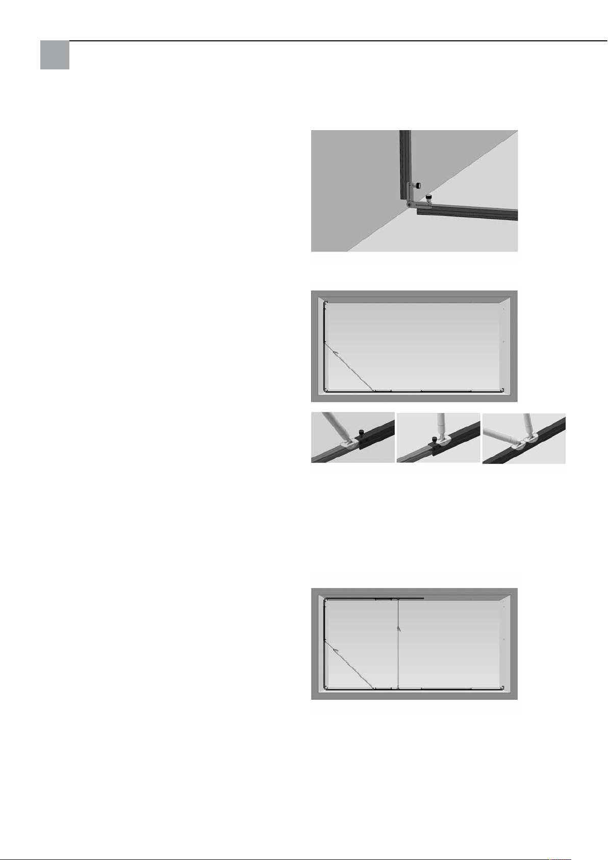
Connection of a T profile with a corner connector
c) Assembly of side elements
Required elements for ceiling height of up to 2,70 m:
1 x T connection profile 150
1 x U intermediate profile 100
1 x T connection profile 25
For the installation of the side elements connect the T
and U profiles so that in each case a T profile is placed at
both ends. Mount a corner connector at the upper end of
the side elements, in each case on the outside. Connect
the side element below with the corner connector of the
floor element, pull apart to the desired height and then
tighten the fixing screws hand-tight.
d) Securing of the side elements with telescopic supports
In order to secure the side element, place the telescopic
support obliquely between the floor and side element.
To do this, place the telescopic support with the support
discs on the tops of the profiles of wall and floor elements, pull out the inner tube by first loosening and then
re-engaging the locking tabs to the right length.
In order to fix and fine-tune the length of the telescopic
supports, press their clamp handles several times until
the support discs are stopped either by the locking screws
of the profiles or by the edges of transitions from T to U
profiles or by support feet of the vertically mounted supports. Exert only as much pressure as necessary to ensure
the tightness of the wall elements.
Note:
For positioning of the support: make sure that the clamp
handles of the telescoping supports are positioned outward. Thus, the handles do not interfere with taping off
the profiles on the inside.
e) Installation of the ceiling element
Put together the ceiling element in the same length as
the floor element (excluding corner connector) with the T
profiles on both ends.
First connect a T and a U profile for about half of the ceiling distance.
Then connect the T element of this part of the ceiling
structure with the corner connector of the side element
and let it hang freely on the side element.
Then stabilize this free-hanging part by means of a telescopic support that you place between the ceiling and the
floor structure and then pull it out.
46
Page 47
The profile elements of the central part of the ceiling
structure are pushed as far as possible in the first part
after it is installed.
On the opposite side, proceed with the installation of the
side element and the rest of the ceiling element as in
described in c to e.
Then they pull the middle part out of the already installed
first side part of the ceiling element, connect it with the
opposite part and tighten the fixing screws.
Note:
If you need to use wheels to enter the separated area,
you can do so by taking out a profile piece from the floor
element.
f) Fine adjustment and securing
On the outside, clamp the corner seals (70 x 70) to the
four corners up and down so that they, if possible, do not
protrude from the side, which is subsequently covered
with the CQ sheeting and that they are positioned evenly
in relation to the profile surface.
For optimal placement of the corner seals and for the
fine adjustment of the Cover Quick Wall
®
, align them
by slightly loosening the screw connections between the
profiles and pulling them out or in to the right length.
Check if the seals of the U and T profiles adhere evenly
to the wall, ceiling and floor surfaces. If the profile seals
do not cling to the surfaces tightly, shift one of the supports so that the pressure is evenly distributed and the
tightness is ensured.
Then tighten all fixing screws to ensure a stable stand
and check if the telescope supports are firmly secured.
47
Page 48
Installation of a Cover Quick® Wall corner separator
a) Defining of the area to be separated
For this purpose, stick the required U and T profiles together, put them at a right angle to each other on the floor and
pull them out to the desired length.
b) Assembly of floor and ceiling elements
Required elements when the max. height is 2,70 m,
width 3,40 m, and depth 2,15 m
Page 1:
2 x T connection profile 100
1 x U intermediate profile 150
Page 2:
1 x T connection profile 25
1 x T connection profile 150
1 x U intermediate profile 50
A T profile must be placed at both ends of the legs of the
floor structure respectively.
At the two outer parts of the floor structure, which are
directed toward the walls, fix a respective corner connector at the upper side of the T profile. The side elements
are joined later with it.
Then connect the other two legs of the floor structure,
lying at right angle to each other, with a corner connector
which you secure with locking screws above the sealing
lips on the T profiles.
Then pull the floor structure apart so that the corner connectors are as close as possible to the walls and then
tighten all locking screws hand-tight.
c) Installation and mounting of side elements
The following installation and mounting of the side elements with telescopic supports is carried out as described
under "Installation of a Cover Quick Wall
®
room separa-
tor" c).
Make sure to attach a corner connector at the upper end
of the side structure that you will then connect with the
ceiling structure.
48
Page 49
d) Installation and fixing of ceiling elements
Put together the two legs of the ceiling structure in the
same length as that of the floor structure, with T profiles
at both ends. Fix them hand-tight with locking screws.
Then connect the external T connection profile of the first
leg of the ceiling structure with the corner connector of
the side element and then stabilize this free-hanging part
by means of a telescopic support that you place between
the ceiling and the floor structure and then pull out.
Proceed similarly with the opposite side with the side and
ceiling element.
Then connect the two legs of the ceiling structure with a
corner connector which you secure with locking screws at
the T profile below the sealing lips.
e) Fine adjustment and securing
Proceed as outlined in point f of "Installation of the Cover
Quickwall
®
wall separator".
In addition, clamp two 80 x 80 floor / ceiling seals in
the T-profiles to the rectangular joints of the floor and the
ceiling structure below the corner joints by putting the 80
x 80 corner seal with the recesses provided, over the T
profiles.
Installation of the Cover Quick® Wall in U
shape
For this purpose, in addition to the basic set, the Cover
Quick Wall® extension set (art. no. 56 55 10) is required.
When installing please follow the installation of the corner solution. The installation sequence is identical and
corresponds to a double corner solution.
49
Page 50

Covering of Cover Quick® Wall structures
The use of Quick Cover® and masking tape is recommended. Cover wall and floor profiles on the side of the construction site with masking tape.
Stick on the Cover Quick® on the inside of the construction site on the ceiling structures, unfold and attach sidewise
with the masking or repair tape. Alternatively, it can also be covered with sheeting.
Note:
By covering the inside of the structure you avoid direct soiling of the elements of the Quick Cover® Wall.
Use of the sheeting door
The sheeting door with a zipper creates a resealable access to the workspace: first outline a matching door frame with
masking tape on the sheeting. Then stick the sheeting door and remove excess sheeting with a cutter or scissors.
50
Page 51
Warranty
Warranty conditions:
A warranty period of twelve months from the date of purchase/date of invoice applies to our tools for commercial
customers. If we have granted an extended warranty period, this period will be noted separately in the operating
manual for the equipment in question.
Claims:
If you wish to claim under our warranty or guarantee, please return the complete device and your invoice to our
logistics centre in Berka, postage paid, or send it to one of our authorised service centres.
Please contact the chargeable STORCH service hotline first: +49 (0)202 . 49 20 – 110.
Your rights under our warranty or guarantee:
Claims can only be accepted for material defects or manufacturing errors, and only assuming intended use of the appliance. Wear parts are not covered by such claims. All claims shall become void in the event of installation of third party
components, improper handling and storage, as well as in the event of obvious disregard of the operating instructions.
Repairs:
All repairs have to be conducted on our premises or by an authorised STORCH service centre.
51
Page 52
CZ
Děkujeme Vám
za důvěru ve firmu STORCH. S nákupem výrobku jste se rozhodli pro kvalitní produkt.
Pokud přesto máte podněty na zlepšení nebo možná nějaký problém, tak bychom byli velmi rádi, kdybyste se nám
ozvali.
Promluvte si s příslušným externím spolupracovníkem naší firmy nebo se v naléhavých případech obracejte přímo na
nás.
S přátelským pozdravem
Servisní oddělení STORCH
Tel.: +49 (0)2 02 . 49 20 - 112
Fax: +49 (0)2 02 . 49 20 - 244
bezplatná linka Hotline-servis: 08 00. 7 86 72 47
bezplatná linka Hotline-objednávky: +49 800. 7 86 72 44
bezplatný fax-objednávky: +49 800. 7 86 72 43
(pouze v Německu)
Obsah Strana
Rozsah dodávky Cover Quick® Wall základní sada 52
®
Rozsah dodávky Cover Quick
Pokyny k použití a péči o Cover Quick
Varianty montáže se základní sadou Cover Quick
Varianty montáže s rozšiřující sadou Cover Quick
Jednotlivé prvky Cover Quick
®
Montáž Cover Quick
Montáž Cover Quick
Montáž Cover Quick
Wall oddělení prostoru 55 - 57
®
Wall oddělení rohu 58 - 59
®
Wall ve tvaru U 59
Zakrytí konstrukcí Cover Quick
Použití fóliových dveří 60
Záruka 61
Wall rozšiřovací sada 53
®
Wall 53
®
Wall 54
®
Wall 54
®
Wall a jejich způsob funkce 55
®
Wall 60
Rozsah dodávky Cover Quick® Wall základní sada (obj. č. 56 55 00)
V tabulce čísel výrobků náhradních dílů a spotřebního materiálu pro dodatečné objednávky
Počet Označení Obj. č.
4 CQ-Wall Teleskopické podpěry 56 55 20
1 Držadlo pro transport - nošení teleskopických podpěr 56 55 25
1 Transportní taška 56 50 50
4 Spojovací T-profil 150 cm 56 55 17
4 Spojovací T-profil 100 cm 56 55 18
4 Spojovací T-profil 25 cm 56 55 19
2 U-meziprofil 150 cm 56 55 14
2 U-meziprofil 100 cm 56 55 15
2 U-meziprofil 50 cm 56 55 16
6 Rohová spojká 56 55 13
4 Rohové těsnění 70x70 mm 56 55 11
2 Podlahové / stropní těsnění 80 x 80 mm 56 55 12
1 Role zakrývací páska 25 mm x 25 m 49 57 25
1 Role opravná páska 48 mm x 50 m stříbrná pro připevnění fóliových dveří 49 07 50
1 Fólie CQ s tkaninovou páskou 270 cm x 20 m K 20 cm 48 98 43
1 Fóliové dveře se zipem 49 91 30
52
Page 53
Rozsah dodávky Cover Quick® Wall rozšiřovací sada (obj. č. 56 55 10)
Počet Označení Obj. č.
1 CQ-Wall Teleskopická podpěra 56 55 20
2 Spojovací T-profil 150 cm 56 55 17
2 Spojovací T-profil 25 cm 56 55 19
2 U-meziprofil 150 cm 56 55 14
2 Rohová spojká 56 55 13
2 Podlahové / stropní těsnění 80 x 80 mm 56 55 12
Pokyny k použití a péči o Cover Quick® Wall
Zajistěte, aby sestavené prvky byly postaveny vždy dobře zajištěné a / nebo pevně namontovány! Kvůli volným a /
nebo ne pevně namontovaným dílům existuje nebezpečí zřícení.
Opatrně u stropů se zavěšenou konstrukcí! Montáž za určitých okolností není možná, protože stropní profily a tlak,
kterým působí teleskopické podpěry, mohou poškodit stropní konstrukci a / nebo nemohou být namontovány dost stabilně.
Překontrolujte před montáží stav a citlivost povrchů (stěny, podlaha a strop)! I přes měkká a bezbarvá pryžová těsnění
profilů nepřebíráme žádnou záruku za vzniklé škody u povrchů. Vyzkoušejte pro jistotu na nenápadném místě reakci pryžových těsnění na tlak tím, že libovolný profil položíte stranou s těsněním na povrch, poněkud vyvinete tlak a
budete třít po povrchu.
Při silných nerovnostech povrchů nebo u přídavných dílů tam nainstalovaných jako kabelová vedení, topné potrubí
nebo obdobné se může stát, že nerovnosti nemohou být přemostěny profily a protiprachový systém nemůže být nainstalován tak, aby těsně uzavíral prostor.
Vždy zajistěte, aby všechny díly a přídavné prvky nebyly poškozeny a bezvadně fungovaly. Pokud by byl jeden z prvků
rozbitý nebo ztracený, lze je přiobjednat pod výše uvedenými obj. č..
Čistěte profily vč. těsnění po každém použití vlhkým čistícím hadříkem. Tím zaručíte spolehlivé přilepení lepících
pásek na povrch profilů a zabráníte případnému znečištění povrchu stěn, stropů a podlah při montáži.
Čistěte rovněž teleskopické podpěry a jejich opěrné desky, aby byla vždy zaručena spolehlivá podpora. Zabraňte kontaktu maziv různého druhu s napínacím zařízením u napínací páky. Napínací síla tím může být snížena.
53
Page 54
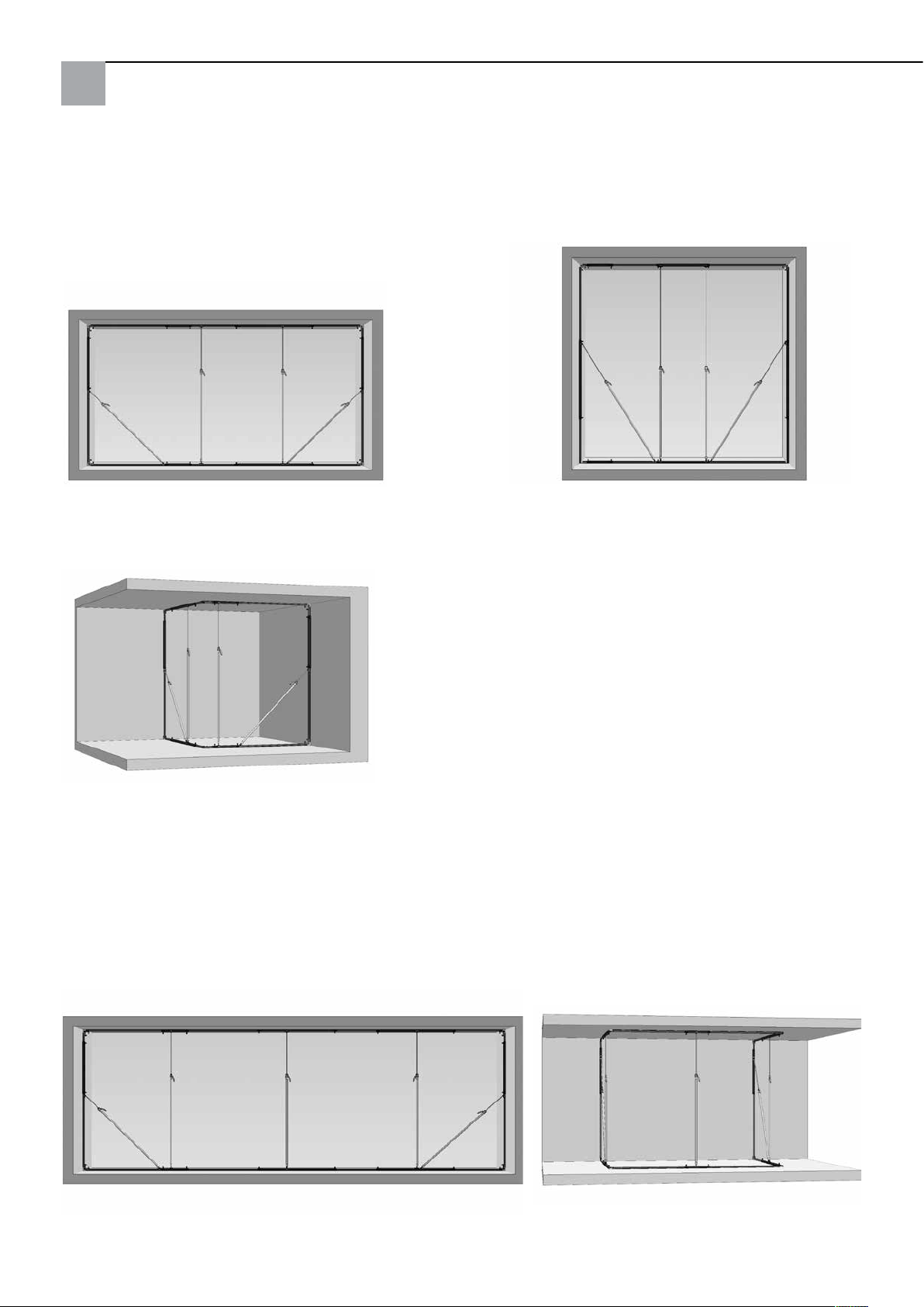
Varianty montáže se základní sadou Cover Quick® Wall (obj. č. 56 55 00)
a) Oddělení prostoru
Maximálně 2,70 m vysoké a 5,30 m široké Maximálně 3,80 m vysoké x 4,00 m široké
b) Oddělení rohu
Maximálně 2,70 m vysoké, 3,40 m široké a 2,15 m
hluboké
Rozměry oddělení lze libovolně plynule přizpůsobit.
Varianty montáže s rozšiřovací sadou Cover Quick® Wall (obj. č. 56 55 10)
S rozšiřovací sadou jsou možné doplňující varianty montáže a zvětšení dříve uvedených variant montáže:
a) Rozšíření oddělení prostoru
Každou rozšiřovací sadou rozšíříte oddělení prostoru
vždy o 2,80 m
b) Oboustranné řešení rohů (U-tvar)
Maximálně 2,70 m vysoké x 2,65 m hluboké
x 3,40 m široké
54
Page 55
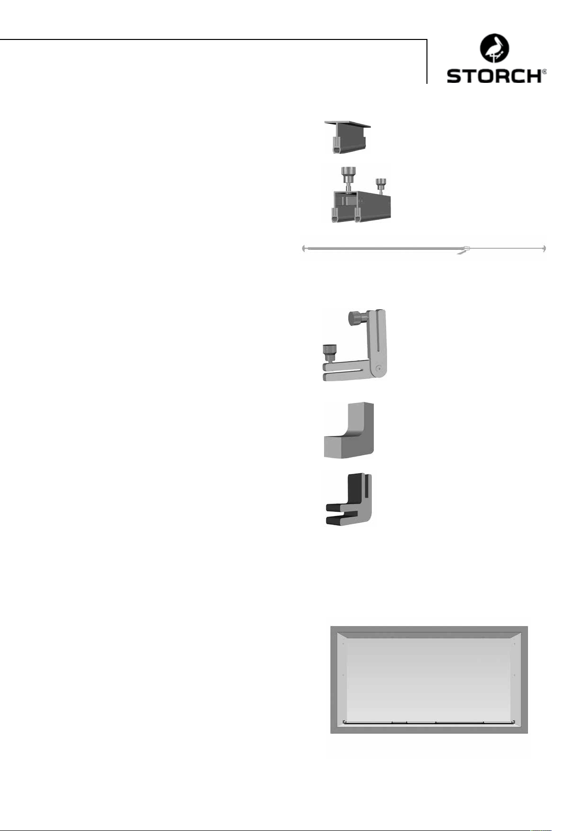
Jednotlivé prvky Cover Quick® Wall a jejich způsob funkce
Spojovací T-profil (25, 100, 150 cm)
Zásadně je třeba na koncích vytvořených konstrukcí
namontovat k dodatečné montáži rohové spojky.
U-meziprofil (50, 100, 150 cm)
Konstrukční prvek, do kterého se spojovací T-profily na
obou stranách zasunou a zafixují zajišťovacími šrouby.
Teleskopická podpěra (lze vytáhnout na max. 380 cm)
K zafixování konstrukce a zaručení těsnosti vyvinutím
tlaku na stěnové, podlahové a stropní konstrukce.
Rohová spojka
Ke spojení podlahových a stropních konstrukcí s
postranními konstrukcemi
Pro montáž zahnutých postranních nebo podlahových
příp. stropních konstrukcí
Montáž výhradně z vnější strany spojovacích T-profilů
Rohové těsnění 70 x 70 mm
K sevření mezi podlahy příp. stropy a stěny a rohové spojky Cover Quick Wall
ochrany povrchů
®
za účelem utěsnění a dodatečné
Rohové těsnění 80 x 80 mm
K osazení v pravoúhlých podlahových a stropních spojkách (řešení rohů a dvojité řešení rohů) pod rohovými
spojkami za účelem utěsnění konstrukce
Montáž Cover Quick® Wall oddělení prostoru
a) Stanovení oddělované oblasti
K tomu účelu T-profily a U-profily střídavě položte na podlahu, spojte a vytáhněte na požadovanou délku.
b) Sestavení podlahových a stropních prvků
Prvky, které jsou třeba, až do montážní šířky 5,30 m:
1 x spojovací T-profil 150
2 x spojovací T-profil 100
1 x U-meziprofil 150,
1 x U-meziprofil 50
Dbejte na to, aby u obou konců byl vždy umístěn jeden
T-profil, na kterém z vnější strany profilu připevníte rohovou spojku.
Konstrukci roztáhněte od sebe tak, aby rohové spojky
přiléhaly co možná blízko u stěn. Potom pevně rukou
dotáhněte fixační šrouby.
55
Page 56
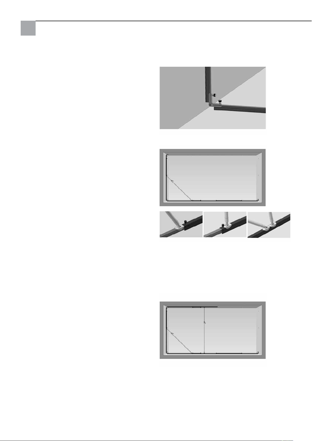
T-profil spojení s rohovou spojkou
c) Sestavení postranních prvků
Prvky, které jsou třeba, až do výšky stropu 2,70 m:
1 x spojovací T-profil 150
1 x U-meziprofil 100
1 x spojovací T-profil 25
Pro montáž postranních prvků T-profily a U-profily spojte tak, aby byl vždy jeden T-profil umístěn u obou konců.
Na horním konci postranních prvků na vnější straně vždy
připevněte rohovou spojku. Postranní prvek dole spojte s rohovou spojkou podlahového prvku, roztáhněte
na požadovanou výšku a potom rukou pevně dotáhněte
fixační šrouby.
d) Zajištění postranních prvků s teleskopickými podpěrami
K zajištění postranního prvku umístěte teleskopickou
podpěru šikmo mezi podlahu a postranní prvek.
K tomu účelu umístěte teleskopickou podpěru s opěrnými
díly na horních stranách profilů u stěnových a podlahových prvků, vytáhněte vnitřní trubku na vhodnou délku při
odpojení a pozdějším opětovném zaklapnutí zajišťovacích
nosů.
K zafixování a přesnému nastavení délky teleskopických
podpěr stiskněte potom několikrát jejich svěrací držadlo
až se opěrné talíře zastaví buď o připevňovací šrouby profilů, o okraje přechodů od T-profilů k U-profilům nebo u
opěrných nožiček svisle namontovaných podpěr. Vyviňte
jenom takový tlak, jaký je potřeba, aby byla zaručena
těsnost stěnových prvků.
Upozornění:
K umístění podpěry dbejte na to:, aby svěrací držadla
teleskopických podpěr byla umístěna směrem ven. Tak
neruší držadla na vnitřní straně při přelepování profilů.
e) Montáž stropního prvku
Stropní prvek sestavte dohromady ve stejné délce jako
podlahový prvek (bez rohové spojky) s T-profily na obou
koncích.
Nejdříve spojte k sobě jeden T-profil a jeden U-profil na
cca polovinu vzdálenosti stropu.
Potom spojte T-prvek tohoto dílu s rohovou spojkou
postranního prvku a nechte ho volně viset u postranního
prvku.
Následně stabilizujte tento volně visící díl pomocí teleskopické podpěry, kterou umístíte a vysunete mezi stropní a podlahovou konstrukci.
56
Page 57
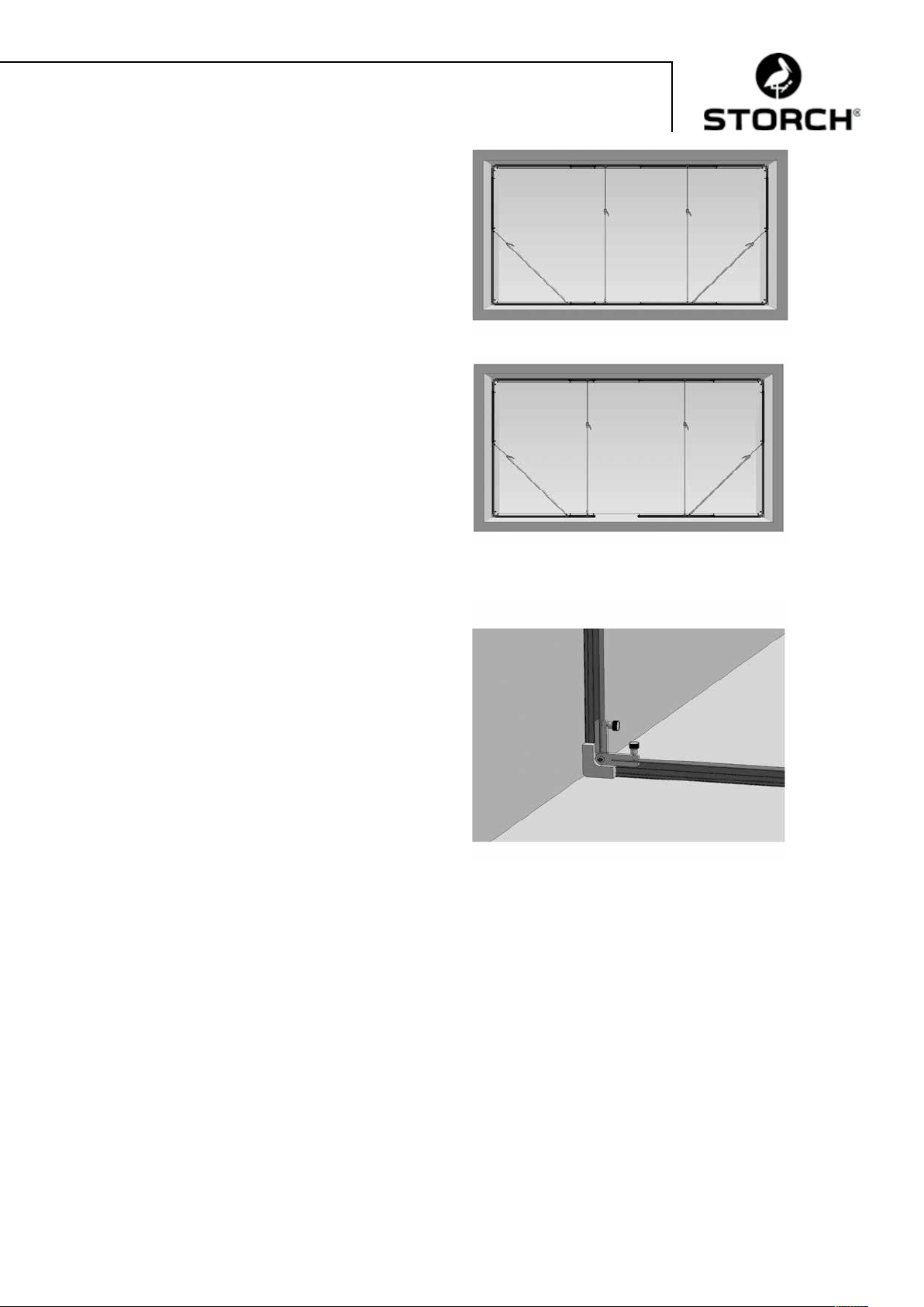
Prvky profilů střední části stropní konstrukce se po
montáži prvního dílu do něj zasunou tak daleko jak je
možné.
Na protější straně postupujte při montáži postranního a
zbytku stropního prvku stejně jako je popsáno pod c. až e.
Následně vytáhněte střední díl ven z již namontovaného
prvního postranního dílu stropního prvku, spojte ho s protějším dílem a dotáhněte zajišťovací šrouby.
Upozornění:
Pokud byste měli potřebu, pojíždět v oddělené části,
můžete rovněž z podlahového prvku odejmout jeden profilový kus.
f) Přesné nastavení a zajištění
Sesvorkujte vně u čtyř rohů nahoře a dole rohová těsnění
(70 x 70), aby na straně, která bude dodatečně polepena fólií CQ, co možná nepřesahovala a byla umístěna v
rovině s povrchem profilu.
K optimálnímu zajištění místa rohových těsnění a pro
přesné nastavení Cover Quick Wall
®
je vyrovnejte tím,
že šroubové spoje mezi profily lehce povolíte a profily
vytáhnete nebo zasunete na vhodnou délku.
Zkontrolujte rovnoměrné opření těsnění U-profiů a T-profilů na stěnových, stropních nebo podlahových plochách.
Pokud by těsnění profilů nebyla u povrchů spojitě
ukončena, přemístěte jednu z podpěr tak, aby byl tlak
rovnoměrněji rozdělen a byla zaručena těsnost.
Následně pro stabilní postavení pevně dotáhněte všechny zajišťovací šrouby a překontrolujte bezpečné usazení
teleskopických podpěr.
57
Page 58
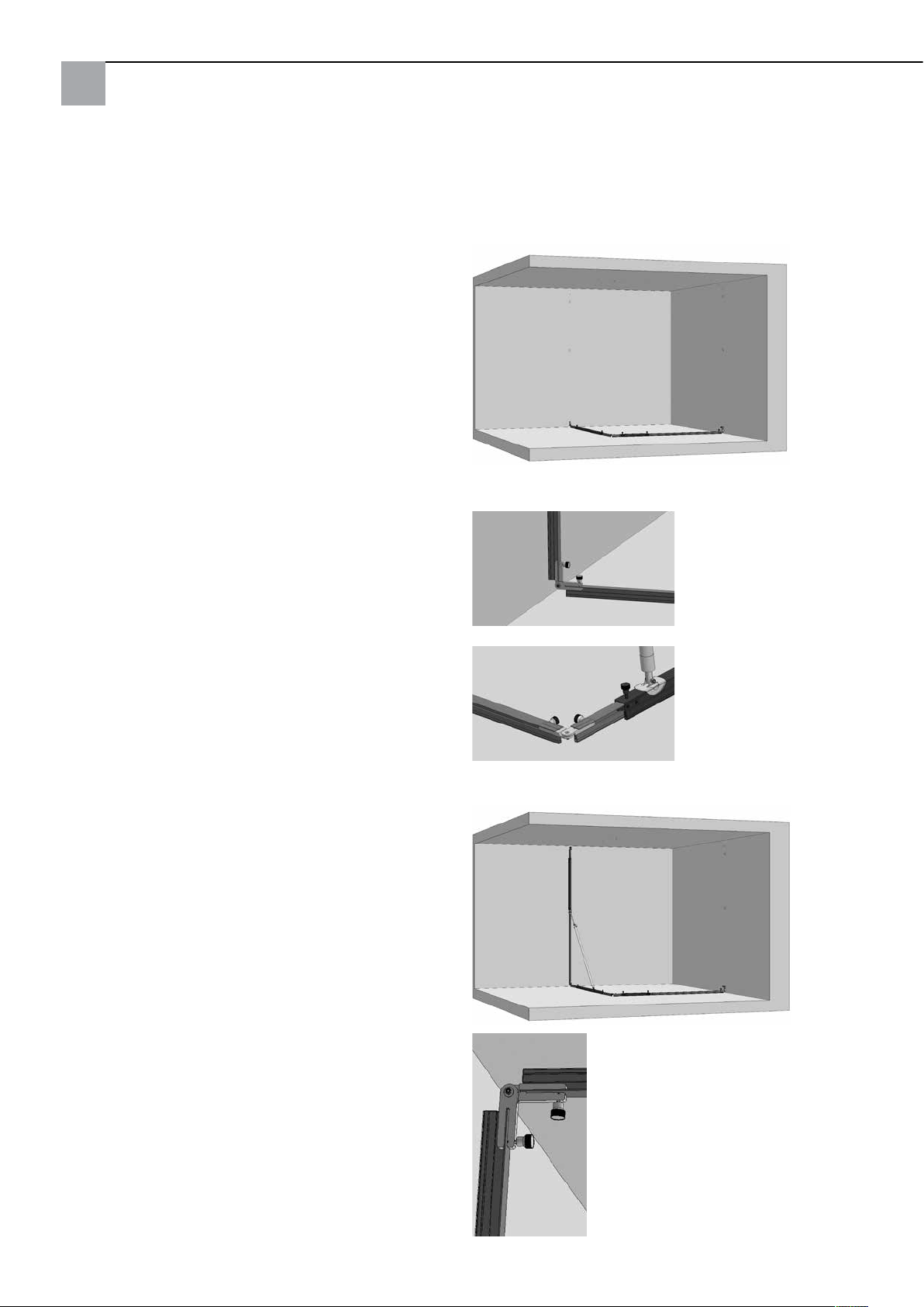
Montáž Cover Quick® Wall oddělení rohu
a) Stanovení oddělované oblasti
K tomu potřebné U-profily a T-profily spojte dohromady, pod pravým úhlem je položte na podlahu a vytáhněte na
požadovanou délku.
b) Sestavení podlahových a stropních prvků
Prvky, které jsou třeba, při maximální výšce 2,70 m,
šířce 3,40 m a hloubce 2,15 m
Strana 1:
2 x spojovací T-profil 100
1 x U-meziprofil 150
Strana 2:
1 x spojovací T-profil 25
1 x spojovací T-profil 150
1 x U-meziprofil 50
Na obou koncích ramen podlahové konstrukce musí být
vždy umístěn jeden T-profil.
Na obou vnějších dílech podlahové konstrukce, které
směřují ke stěnám, připevněte vždy jednu rohovou spojku
na horní straně T-profilu. S ní se později spojí postranní
prvky.
Spojte potom pod pravým úhlem obě k sobě umístěná
ramena podlahové konstrukce s rohovou spojkou, kterou
zafixujete zajišťovacími šrouby nad těsnícími chlopněmi u
T-profilů.
Podlahovou konstrukci potom roztáhněte tak, aby rohové spojky co možná blízko přiléhaly u stěn a potom rukou
pevně dotáhněte zajišťovací šrouby.
c) Montáž a zafixování postranních prvků
Následující montáž a zafixování postranních prvků
pomocí teleskopických podpěr se provede jak je popsáno
pod „Montáž Cover Quick Wall
®
oddělení prostoru“ c).
Dbejte na to, abyste u horního konce postranní konstrukce umístili rohovou spojku, kterou následně spojíte se
stropní konstrukcí.
58
Page 59
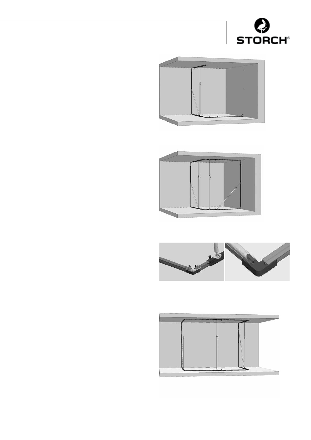
d) Montáž a zafixování stropních prvků
Obě ramena stropní konstrukce sestavte dohromady ve
stejné délce jako je u podlahové konstrukce s T-profily na
obou koncích. Zafixujte je pevně dotažením zajišťovacích
šroubů rukou.
Potom spojte vnější spojovací T-profil prvního ramena
stropní konstrukce s rohovou spojkou postranního prvku a
stabilizujte následně tento volně visící díl prvku pomocí
teleskopické podpěry, kterou umístíte a vysunete mezi
stropní a podlahovou konstrukci.
Stejně postupujte na protější straně s postranním a stropním prvkem.
Následně spojte obě ramena stropní konstrukce s rohovou spojkou, kterou zafixujete zajišťovacími šrouby pod
těsnícími chlopněmi u T-profilu.
e) Přesné nastavení a zajištění
Za tím účelem postupujte jak je uvedeno pod f u
„Montáže Cover Quick Wall
®
oddělení u stěny“.
Dodatečně sesvorkujte u pravoúhlých spojovacích míst
podlahové a stropní konstrukce pod rohovou spojkou dvě
80 x 80 podlahová / stropní těsnění do T-profilů, tím
že rohové těsnění 80 x 80 přetáhnete k tomu určenými
drážkami přes T-profily.
Montáž Cover Quick® Wall ve tvaru U
K tomu účelu je dodatečně třeba k základní sadě Cover
Quick Wall
K montáži se orientujte dle montáže při řešení rohů.
Pořadí montáže je identické a odpovídá dvojitému řešení
rohů.
®
ještě rozšiřovací sada (obj. č. 56 55 10).
59
Page 60

Zakrytí konstrukcí Cover Quick® Wall
Doporučuje se použití Cover Quick® a zakrývací pásky. Stěnové a podlahové profily oblepte zakrývací páskou na straně
umístěné ke stavbě.
Cover Quick
®
na vnitřní straně umístěné ke stavbě nalepte na stropní konstrukce, rozložte a na straně zafixujte
zakrývací nebo opravnou páskou. Alternativně můžete pro zakrytí použít i fólii.
Upozornění:
Zakrytím na vnitřní straně konstrukce, zabráníte přímému znečištění prvků Cover Quick
®
Wall.
Použití fóliových dveří
S fóliovými dveřmi se zipem vzniká přístup do pracovní oblasti, který lze znovu uzavřít: Nejdříve nalepte na fólii vhodný rám dveří zakrývací páskou. Na to přilepte fóliové dveře a přebytečnou folii odstraňte řezacím nožem nebo nůžkami.
60
Page 61
Záruka
Záruční podmínky:
U našich zařízení platí zákonné záruční lhůty 12 měsíců od data zakoupení/data faktury obchodního konečného zákazníka. Pokud jsou delší lhůty v cestě námi vypsanému prohlášení o záruce, jsou zvláště vyznačeny v návodu k obsluze
příslušných zařízení.
Uplatňování:
V případě záručního příp. garančního případu žádáme, aby bylo zasláno kompletní zařízení dohromady s fakturou do
našeho střediska Logisitk Center v Berka nebo do námi autorizované servisní stanice.
Kontaktujte prosím nejdříve placený hotline servis firmy STORCH: +49 (0)202 . 49 20 – 110.
Nárok na záruku příp. garanci
Nároky na záruku existují výhradně u materiálu nebo výrobní vady a také výhradně při používání přístroje v souladu s
určeným účelem. Díly podléhající opotřebení nespadají do nároků na záruku. Veškeré nároky zanikají zamontováním
dílů cizího původu, při nepřiměřeném zacházení a skladování a také při zřejmém nedodržování provozního návodu.
Provádění oprav
Veškeré opravy smějí být prováděny výhradně naším závodem nebo servisními stanicemi autorizovanými firmou
STORCH.
61
Page 62

626364
Page 63
Page 64
Art.-Nr. Bezeichnung
56 55 00 Cover Quick Wall
56 55 10 Cover Quick Wall
®
Basis-Set
®
Erweiterungs-Set
Art. nr. Beschrijving
56 55 00 Cover Quick Wall
®
basisset
56 55 10 Cover Quick Wall® uitbreidingsset
Référence Désignation
56 55 00 Kit de base Cover Quick Wall
56 55 10 Kit d‘extension Cover Quick Wall
®
®
N. art. Denominazione
56 55 00 Set di base Cover Quick Wall
®
56 55 10 Set di ampliamento Cover Quick Wall
®
Art. no. Description
56 55 00 Cover Quick Wall
56 55 10 Cover Quick Wall
®
Basic Set
®
Extension Set
Výr. č. Označení
56 55 00 Cover Quick Wall
®
základní sada
56 55 10 Cover Quick Wall® rozšiřovací sada
H 002715
08-2014
Malerwerkzeuge & Profigeräte GmbH
Platz der Republik 6 - 8
D-42107 Wuppertal
Telefon: +49 (0)2 02 . 49 20 - 0
Telefax: +49 (0)2 02 . 49 20 - 111
[email protected]
www.storch.de
 Loading...