

Page 1
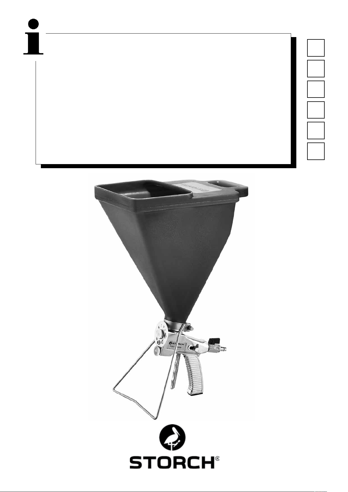
Putzpistole
DE
Pistool voor pleisters
Pistolet à enduire
Pistola per intonaco
Plaster gun
Omítací pistole
NL
FR
IT
GB
CZ
1
Page 2

DE
Vielen Dank
für Ihr Vertrauen zu STORCH. Mit dem Kauf haben Sie sich für ein Qualitäts-Produkt entschieden.
Haben Sie trotzdem Anregungen zur Verbesserung oder aber vielleicht einmal ein Problem, so freuen wir uns sehr, von
Ihnen zu hören.
Bitte sprechen Sie mit Ihrem Außendienst-Mitarbeiter oder in dringenden Fällen auch mit uns direkt.
Mit freundlichen Grüßen
STORCH Service Abteilung
Telefon: +49 (0)2 02 . 49 20 - 112
Fax: +49 (0)2 02 . 49 20 - 244
kostenlose Service-Hotline: 08 00. 7 86 72 47
kostenlose Bestell-Hotline: 08 00. 7 86 72 44
kostenloses Bestell-Fax: 08 00. 7 86 72 43
(nur innerhalb Deutschlands)
Inhaltsverzeichnis Seite
Lieferumfang 2
Verarbeitbare Materialien 2
Wechsel der Düsenöffnung 3
Einstellung der Luftmenge 3
Konsistenz der Materialmischung 3
Einstellung der Materialzufuhr 3
Reinigung des Gerätes 3
Detailzeichnung 4
Ersatzteilliste 4
Garantie 5
Lieferumfang
Putzpistole, Trichter, Standfuß mit Befestigungsschelle, Bedienungsanleitung.
Verarbeitbare Materialien
Dekorative Oberputze, flüssige Raufaser, Armierungskleber, Plastikmassen, Quartzsandputz bis 6 mm, Trockenquarz
bis 8 mm, Faserputz und vieles mehr.
2
Page 3

1. Wechsel der Düsenöffnung
Für eine gute Materialstruktur sollten Sie mindestens den doppelten Durchmesser wählen, den die größte Mörtelkörnung hat.
Lösen Sie hierzu die beiden Rändelmuttern (3). Bei gezogenem Abzugsbügel läßt sich die Düsenscheibe (2) mit den
Bohrungsdurchmessern 4 - 13 mm leicht in die gewünschte Stellung drehen.
Achten Sie darauf, daß der Dichtring (5) hinter der Düsenscheibe sauber anliegt. Durch Lösen des Abzugbügels wird die
Düse zur Bohrung zentriert. Die obere, danach die untere Rändelmutter können anschließend wieder angezogen wer-
den.
2. Einstellung der Luftmenge
Der Luftbedarf der Putzpistole liegt bei ca. 220 l / min. Ein Arbeitsdruck von 2 - 3 bar genügt in der Regel für alle
Spritzarbeiten.
Die Luftmenge können Sie mit dem Hochdruckhahn an der Putzpistole leicht verstellen. Je mehr Luft Sie eingestellt
haben, um so feiner wird Ihre Spritzstruktur. Wenn Sie mit zu viel Luft arbeiten, können die Sandkörner vom Bindemittel getrennt werden und von der Wand zurückprallen. Dies führt zu Materialverlust und Verschmutzung.
3. Konsistenz der Materialmischung
Eine wichtige Voraussetzung für zuverlässiges Arbeiten ist die Verwendung von gleichmäßig gemischtem und von groben Verunreinigungen freiem Material. Es ist erforderlich, den Mörtel so dick zu halten, daß es in der Trichterpistole
gerade noch nachrutscht. Die Mörteltröpfchen bleiben dann an der Verputzfläche gut stehen und bilden eine schöne
Struktur.
Es ist jedoch meist falsch, den Mörtel dünner anzurühren, wenn eine feinere Struktur gewünscht wird. In diesem Fall
ist es besser, eine kleinere Düse oder eine höhere Luftmenge einzustellen.
4. Einstellung der Materialzufuhr
An der Seite des Pistolengriffes ist eine Flügelschraube angebracht, womit Sie die Menge des kontinuierlich benötigten
Materials einstellen und arretieren können. Beachten Sie bitte als Faustregel, daß der Abstand zwischen Luftdüse (24)
und Materialführungsdüse (6) etwas größer als die gewählte Düsenbohrung sein muß. Diesen Abstand kann man bei
abgeschraubter Düsenscheibe (2) überprüfen.
In kurzer Zeit werden Sie festgestellt haben, wieviel Material und welche Einstellung der Trichterpistole für Ihre Arbeit
richtig ist.
5. Reinigung des Gerätes
Bitte regelmäßig gründlich mit Wasser auswaschen, die Düsenöffnung durchblasen und äußerlich reinigen.
Diese Pflege und Sauberhaltung macht sich durch zuverlässige Arbeitsweise bezahlt.
3
Page 4
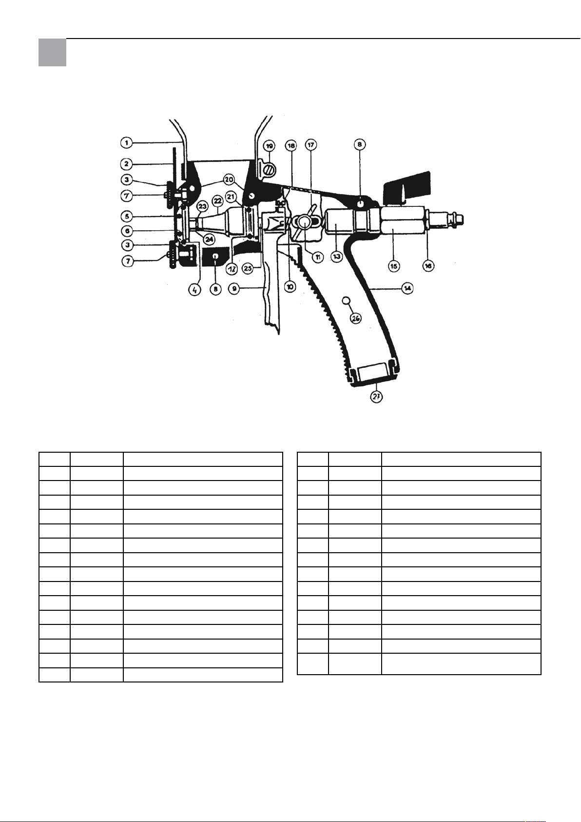
Detailzeichnung
Ersatzteilliste
Pos. Art.-Nr. Bezeichnung
1 63 18 51 Trichter
2 63 18 52 9-Loch Düsenscheibe
3 63 18 56 Rändelmutter
4 63 18 95 O-Ring
5 63 18 80 O-Ring
6 63 18 89 Materialdüse
7 63 18 44 Schraube M5 x 14
8 63 18 36 Schraube M5 x 14
9 63 18 65 Abzugbügel lang
10 63 18 69 Druckfeder
11 63 18 45 Schraube M6 x 16
12 63 18 97 O-Ring
13 63 18 98 Hauptführung
14 63 18 83 Pistolenkörper rechts
63 18 84 Pistolenkörper links
Pos. Art.-Nr. Bezeichnung
15 63 18 93 Kugelhahn
16 60 39 09 Stecknippel 1/4“ AG
17 63 18 46 Flügelmutter M6
18 63 18 48 Schraube M5 x 8
19 63 18 81 Befestigungsschelle
20 63 18 34 Schraube M5 x 22
21 63 18 96 Luftrohrführung
22 63 18 60 Membrane
23 63 18 47 Kupferring
24 63 18 59 Luftdüse
25 63 18 64 Luftrohr
26 63 18 35 Schraube M5 x 10
27 63 18 88 Griffverschluß
o.
63 18 03 Standfuß mit Befestigungsschelle
Abb.
4
Page 5

Garantie
Garantiebedingungen
Für unsere Geräte gelten die gesetzlichen Gewährleistungsfristen von 12 Monaten ab Kaufdatum / Rechnungsdatum
des gewerblichen Endkunden.
Geltendmachung
Bei Vorliegen eines Gewährleistungs- bzw. Garantiefalles bitten wir, dass das komplette Gerät zusammen mit der
Rechnung frei an unser Logistik Center in Berka oder an eine von uns autorisierte Service-Station eingeschickt wird.
Bitte setzen Sie sich vorher mit der STORCH Service-Hotline in Verbindung: 08 00. 7 86 72 47
Gewährleistungs- bzw. Garantieanspruch
Ansprüche bestehen ausschließlich an Werkstoff- oder Fertigungsfehler sowie ausschließlich bei bestimmungsgemäßer
Verwendung des Geräts. Verschleißteile fallen nicht unter derartige Ansprüche. Sämtliche Ansprüche erlöschen durch
den Einbau von Teilen fremder Herkunft, bei unsachgemäßer Handhabung und Lagerung sowie bei offensichtlicher
Nichtbeachtung der Betriebsanleitung.
Durchführung von Reparaturen
Sämtliche Reparaturen dürfen ausschließlich durch unser Werk oder von STORCH autorisierten Service-Stationen
durchgeführt werden.
5
Page 6

NL
Hartelijk dank
voor uw vertrouwen in STORCH. Met deze aankoop hebt u voor een kwaliteitsproduct gekozen.
Als u desondanks suggesties voor verbetering of een probleem hebt, dan horen wij graag van u.
Neem contact op met de buitendienst-medewerker of in dringende gevallen rechtstreeks met ons.
Met vriendelijke groeten,
STORCH serviceafdeling
Telefoon: +49 (0)2 02 . 49 20 - 112
Fax: +49 (0)2 02 . 49 20 - 244
Gratis service-hotline: 08 00. 7 86 72 47
Gratis bestel-hotline: 08 00. 7 86 72 44
Gratis bestel-fax: 08 00. 7 86 72 43
(alleen binnen Duitsland)
Inhoudsopgave Pagina
Levering 6
Te verwerken materialen 6
Wisselen van de sproeikopopening 7
Instelling van de luchthoeveelheid 7
Consistentie van de materiaalmenging 7
Instelling van de materiaaltoevoer 7
Reiniging van het apparaat 7
Detailtekening 8
Lijst met vervangende onderdelen 8
Garantie 9
Levering
Pistool voor pleisters, trechter, standvoet met bevestigingsring, gebruiksaanwijzing.
Te verwerken materialen
Zo kunt u decoratieve pleisters, vloeibare rauhfaser, versterkingsmuurlijm, kunststofmassa's, kwartszandpleisters tot 6
mm, droge kwarts tot 8 mm, vezelpleisters en veel meer verwerken.
6
Page 7

1. Wisselen van de sproeikopopening
Voor een goede materiaalstructuur moet u minstens de dubbele diameter dan die van de mortelkorrel kiezen.
Draai hiertoe de beide kartelmoeren (3) los. Bij overgehaalde trekker kan de sproeierschijf (2) met de boringdiameters
4 - 13 mm eenvoudig in de gewenste positie worden gedraaid.
Let erop dat de dichtingsring (5) goed achter de schijf is geplaats. Bij het loslaten van de trekker wordt de sproeierkop
gecentreerd t.o.v. de boring. De bovenste en daarna de onderste kartelmoeren kunnne vervolgens weer vastgedraaid.
2. Instelling van de luchthoeveelheid
De benodigde luchthoeveelheid van het pistool is ca. 220 l / min. Een werkdruk van 2 - 3 bar is in de regel voldoende
voor alle spuitwerkzaamheden.
U kunt de luchthoeveelheid eenvoudig verstellen met de hogedrukknop op het pistool. Hoe meer lucht u instelt,
hoe fijner de spuitstructuur wordt. Als u met te veel lucht werkt, kunnen de zandkorrels van het bindmiddel worden
gescheiden en van de muur terugspringen. Dit leidt tot materiaalverlies en vervuiling.
3. Consistentie van de materiaalmenging
Een belangrijke voorwaarde voor betrouwbaar werken is het gebruik van gelijkmatig gemengd materiaal zonder grove
verontreinigingen. Het is noodzakelijk om de mortel zo dik te houden dat het in het trechterpistool net nog doorglijdt.
De morteldruppels blijven dan goed staan op het pleistervlak en vormen een mooie structuur.
Het is echter meestal verkeerd om de mortel dunner aan te roeren wanneer er een fijnere structuur is gewenst. In dit
geval is het beter een kleinere sproeierkop of een grotere luchthoeveelheid in te stellen.
4. Instelling van de materiaaltoevoer
Aan de kant van de pistoolgreep is een vleugelmoer aangebracht waarmee de hoeveelheid van het continu vereiste
materiaal kan worden ingesteld en bepaald. Neem als vuistregel dat de afstand tussen sproeierkop (24) en de materiaaldoorvoer (6) iets groter dan de gekozen sproeierkopboring moet zijn. Deze afstand kan bij losgeschroefde sproeierschijf (2) worden gecontroleerd.
U merkt snel hoeveelheid materiaal en welke instelling van het pistool voor uw werk juist zijn.
5. Reiniging van het apparaat
Regelmatig grondig met water afwassen, de sproeierkop doorblazen en extern reinigen.
Dankzij dit onderhoud en de reiniging kunt u het pistool betrouwbaar gebruiken.
7
Page 8
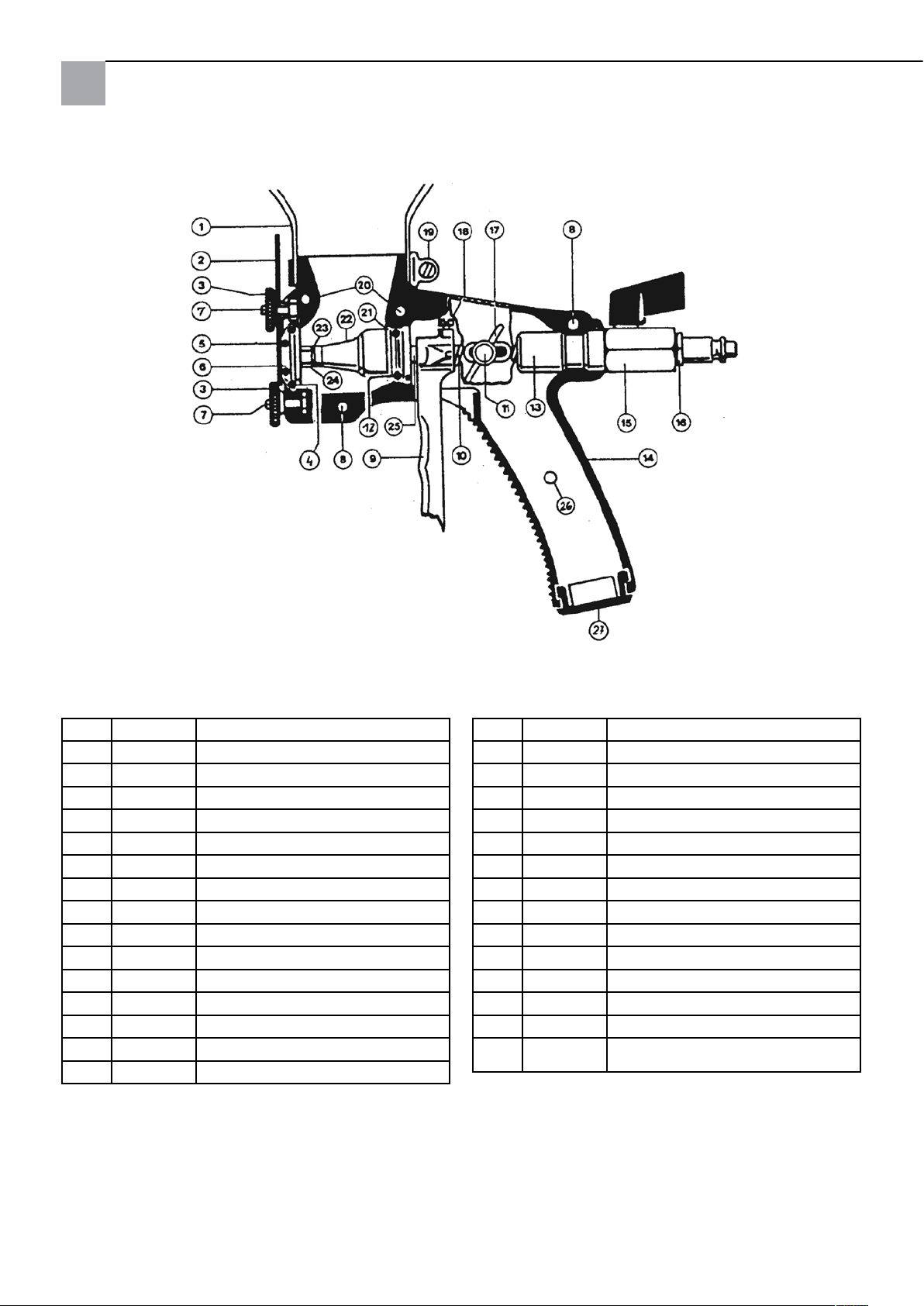
Detailtekening
Lijst met vervangende onderdelen
Pos. Art. nr. Benaming
1 63 18 51 Trechter
2 63 18 52 9-gats sproeierschijf
3 63 18 56 Kartelmoer
4 63 18 95 O-ring
5 63 18 80 O-ring
6 63 18 89 Materiaalsproeierkop
7 63 18 44 Schroef M 5 x 14
8 63 18 36 Schroef M 5 x 14
9 63 18 65 Trekker lang
10 63 18 69 Drukveer
11 63 18 45 Schroef M 6 x 16
12 63 18 97 O-ring
13 63 18 98 Hoofdgeleiding
14 63 18 83 Pistoolbehuizing rechts
63 18 84 Pistoolbehuizing links
Pos. Art. nr. Benaming
15 63 18 93 Bolkraan
16 60 39 09 Steeknippel 1/4“ AG
17 63 18 46 Vleugelmoer M 6
18 63 18 48 Schroef M 5 x 8
19 63 18 81 Bevestigingsring
20 63 18 34 Schroef M 5 x 22
21 63 18 96 Luchtbuisgeleiding
22 63 18 60 Membraan
23 63 18 47 Koperring
24 63 18 59 Sproeierkop
25 63 18 64 Luchtbuis
26 63 18 35 Schroef M 5 x 10
27 63 18 88 Greepsluiting
zonder
63 18 03 Standvoet met bevestigingsring
afb.
8
Page 9

Garantie
Garantievoorwaarden:
Voor onze apparaten gelden de wettelijke garantieperioden van 12 maanden vanaf aankoopdatum/factuurdatum van
de eindklant. Indien wij langere perioden in een garantieverklaring hebben toegezegd, dan worden deze speciaal in de
gebruiksaanwijzingen van de desbetreffende apparaten toegelicht.
Indienen van garantieclaims:
Bij een garantieclaim vragen wij u het gehele apparaat samen met de rekening franco aan ons logistiekcentrum in Berka of naar een door ons geautoriseerd servicestation te verzenden.
Neem eerst contact op met de STORCH Service-Hotline (hiervoor worden kosten in rekening gebracht):
+49 (0)202 . 49 20 – 110.
Garantieclaims
Claims uitsluitend met betrekking tot materiaal- of productiefouten en uitsluitend bij gebruik van het apparaat conform
de voorschriften. Voor verbruiksartikelen gelden deze aanspraken niet. Alle claims komen te vervallen bij inbouw van
onderdelen van andere fabrikanten, bij een ondeskundig gebruik en ondeskundige opslag alsmede bij aantoonbare veronachtzaming van de bedrijfshandleiding.
Reparaties uitvoeren
Reparaties mogen uitsluitend door onze fabriek of door STORCH geautoriseerde servicestations worden uitgevoerd.
9
Page 10

FR
Merci
pour la confiance que vous témoignez à STORCH. En achetant ce produit, vous avez opté pour un produit de qualité.
Si vous avez des suggestions d'amélioration ou si vous rencontrez des problèmes, nous sommes à votre écoute.
Contactez votre représentant du service après-vente ou contactez-nous directement en cas d'urgence.
Sincères salutations
SAV STORCH
Téléphone : +49 (0)2 02 . 49 20 - 112
Télécopie : +49 (0)2 02 . 49 20 - 244
Ligne d'assistance SAV gratuite : +49 800 7 86 72 47
Service gratuit de commande par téléphone : +49 800. 7 86 72 44
Fax de commande gratuit : +49 800. 7 86 72 43
(uniquement en Allemagne)
Table des matières Page
Etendue des fournitures 10
Matériaux transformables 10
Remplacement de l'orifice de la buse 11
Réglage de la quantité d'air 11
Consistance du mélange de matériaux 11
Réglage de l'alimentation en matériau 11
Nettoyage de l'appareil 11
Dessin détaillé 12
Nomenclature 12
Garantie 13
Etendue des fournitures
Pistolet à enduire, entonnoir, pied avec collier de fixation, mode d'emploi.
Matériaux transformables
Enduits de finition décoratifs, papiers ingrain fluides, colles de renforcement, masses plastiques, enduit de sable de
quartz jusqu'à 6 mm, quartz sec jusqu'à 8 mm, crépis et bien plus.
10
Page 11

1. Remplacement de l'orifice de la buse
Pour que le matériau présente une structure satisfaisante, vous devez choisir un diamètre de buse dont la dimension
soit au minimum le double de la plus grosse granulation du mortier.
Pour effectuer le remplacement, devissez les deux écrous moletés (3). Lorsque la sous-garde est tirée, le disque de
buse (2) peut alors facilement tourner dans la position souhaitée en utilisant les diamètres de perçage 4 - 13 mm.
Veillez à ce que la bague d'étanchéité (5) soit nettement appuyée à l'arrière du disque de buse. En dévissant la sousgarde, la buse est alors centrée par rapport au trou de perçage. Vous pouvez ensuite revisser l'écrou moleté supérieur,
puis l'écrou inférieur.
2. Réglage de la quantité d'air
La consommation d'air du pistolet à enduire est de 220 l/mn. En règle générale, une pression de service de 2 - 3 bars
est suffisante pour tous les travaux de pulvérisation.
Vous pouvez régler facilement le robinet à haute pression sur le pistolet à enduire. Plus vous utilisez une quantité d'air
importante, plus la structure pulvérisée devient fine. Si vous travaillez avec une trop grande quantité d'air, les grains
de sable peuvent se désolidariser du liant et rebondir sur le mur. Cela a pour conséquence un gaspillage de matériau et
l'encrassement du lieu de travail.
3. Consistance du mélange de matériaux
Une condition préalable à un travail fiable est l'utilisation d'un matériau mélangé uniformément et exempt d'impuretés.
Il est nécessaire de maintenir le mortier épais de telle sorte qu'il puisse encore s'écouler directement dans le pistolet en
entonnoir. Les gouttes de mortier adhèrent bien à la surface enduite et forment une structure d'un bel aspect.
Cependant, c'est bien souvent une erreur de vouloir gâcher plus finement le mortier si vous souhaitez obtenir une structure plus fine. Dans ce cas, il vaut mieux utiliser une buse plus petite ou une plus grande quantité d'air.
4. Réglage de l'alimentation en matériau
Une vis à oreilles est montée sur le côté de la poignée du pistolet et vous permet de régler en continu et de bloquer la
quantité de matériau nécessaire. A cet égard, veuillez respecter comme règle principale que l'écart entre la buse d'air
(24) et la buse d'alimentation en matériau (6) doit être quelque peu plus grand que le trou de la buse souhaité. Vous
pouvez vérifier cet écart le disque de buse dévissé (2).
Vous pourrez rapidement définir quelle quantité de matériau et quel réglage du pistolet en entonnoir sont adaptés à
votre travail.
5. Nettoyage de l'appareil
Nettoyer entièrement l'appareil avec de l'eau à intervalles réguliers, purger l'ouverture de la buse, puis la nettoyer
superficiellement.
Cet entretien et ce nettoyage permettent d'obtenir un travail fiable.
11
Page 12
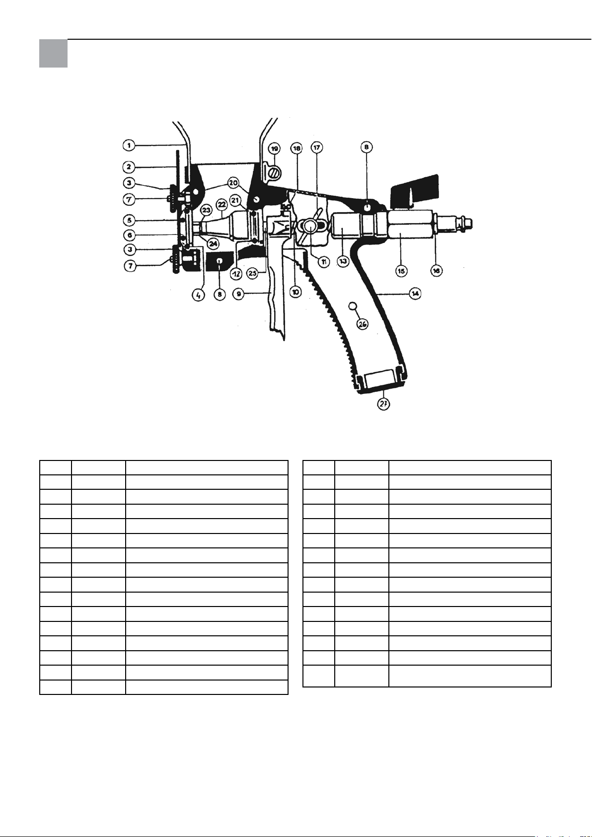
Dessin détaillé
Nomenclature
Pos. Réf. art. Désignation
1 63 18 51 Entonnoir
2 63 18 52 Disque de buse à 9 trous
3 63 18 56 Ecrou moleté
4 63 18 95 Joint torique
5 63 18 80 Joint torique
6 63 18 89 Buse de matériau
7 63 18 44 Vis M5 x 14
8 63 18 36 Vis M5 x 14
9 63 18 65 Sous-garde longue
10 63 18 69 Ressort de pression
11 63 18 45 Vis M6 x 16
12 63 18 97 Joint torique
13 63 18 98 Guidage principal
14 63 18 83 Corps de pistolet à droite
63 18 84 Corps de pistolet à gauche
Pos. Réf. art. Désignation
15 63 18 93 Vanne sphérique
16 60 39 09 Embout enchable 1/4“ AG
17 63 18 46 Ecrou papillon M6
18 63 18 48 Vis M5 x 8
19 63 18 81 Collier de xation
20 63 18 34 Vis M5 x 22
21 63 18 96 Guidage de tube à air
22 63 18 60 Membrane
23 63 18 47 Anneau en cuivre
24 63 18 59 Buse d'air
25 63 18 64 Tube à air
26 63 18 35 Vis M5 x 10
27 63 18 88 Fermeture de poignée
sans
63 18 03 Pied avec collier de xation
ill.
12
Page 13

Garantie
Conditions de garantie
Les durées de garantie légales de 12 mois à compter de la date d‘achat / de la facture du client final professionnels
s‘appliquent à nos appareils. Si nous mentionnons des délais supérieurs dans le cadre d‘une déclaration de garantie,
ceux-ci sont mentionnés dans les instructions de service des appareils concernés.
Exercice
Dans un cas couvert par la garantie, nous vous demandons de renvoyer l‘appareil complet franco à notre centre logistique à Berka accompagné de la facture ou de l‘expédier à une station SAV agréée par nous.
Veuillez contacter préalablement l‘assistance téléphonique payante de la société STORCH: +49 (0)202 . 49 20 – 110.
Demande de prise en garantie
Les droits ne concernent que les défauts de matériau et de production ainsi qu'exclusivement avec une utilisation conforme de l'appareil. Les pièces d'usure ne peuvent pas faire l'objet d'une demande de garantie. Tous les droits arrivent
à expiration avec l'intégration de pièces d'autres fabricants, en cas de manipulation et de stockage non conforme ainsi
qu'en cas de non-respect manifeste du mode d'emploi.
Exécution de réparations
Toutes les réparations doivent être exclusivement réalisées par notre usine ou par les services après-vente agréés par
STORCH.
13
Page 14

IT
Grazie
per la Vostra fiducia nella STORCH. Con l'acquisto avete scelto un prodotto di qualità.
Nel caso abbiate dei suggerimenti per il perfezionamento oppure un problema, saremo lieti di assisterVi.
Contattate il Vostro rappresentante oppure rivolgeteVi direttamente a noi in casi urgenti.
Distinti saluti
STORCH Reparto Assistenza
Tel.: 02 - 66 22 77 15
Indice del contenuto Pagina
Materiale compreso nella fornitura 14
Materiali lavorabili 14
Modifica dell'apertura dell'ugello 15
Impostazione della quantità dell'aria 15
Consistenza del materiale 15
Regolazione dell’alimentazione di materiale 15
Pulizia dell'apparecchio 15
Disegno dettagliato 16
Elenco dei pezzi di ricambio 16
Garanzia 17
Elementi forniti a corredo
Pistola per intonaco, imbuto, piede di appoggio con fascetta di fissaggio, istruzioni per l'uso.
Materiali lavorabili
Intonaci superiori decorativi, fibre ruvide liquide, colle per armatura, materiali plastici, intonaci con sabbia quarzifera
fino a 6 mm, quarzo secco fino a 8 mm, intonaci a fibre e molto più.
14
Page 15

1. Modifica dell'apertura dell'ugello
Per ottenere una buona struttura del materiale è consigliabile scegliere un diametro doppio rispetto alla grossezza massima della grana della malta.
Svitare entrambi i dadi zigrinati (3). Con la leva di scatto tirata è possibile ruotare facilmente il disco degli ugelli (2) con
fori da 4 a 13 mm nella posizione desiderata.
Fare attenzione che l’anello di guarnizione (5) posto dietro il disco aderisca bene. Lasciando la leva di scatto l’ugello
viene centrato rispetto al foro. Dopo di ciò è possibile serrare nuovamente prima il dado in alto e poi quello in basso.
2. Impostazione della quantità dell'aria
La pistola necessita di una quantità d’aria di circa 220 l/min. Una pressione di 2-3 bar è in genere sufficiente per ogni
tipo di lavoro.
La quantità d’aria può essere facilmente regolata mediante il rubinetto ad alta pressione posto sulla pistola. Maggiore è
la quantità d’aria più fine è il tipo di spruzzo che si ottiene. Lavorando con una quantità d’aria eccessiva è possibile che
i grani di sabbia si separino dal legante e rimbalzino sulla parete. Ciò causa imbrattamento e una perdita di materiale.
3. Consistenza del materiale
Un importante presupposto per un lavoro di qualità è l’utilizzo di materiale mescolato in modo omogeneo e privo di
impurità. E’ necessario tenere la malta così spessa che riesca appena a scorrere nella pistola. In tal caso le goccioline di
malta aderiscono bene alla superficie da intonacare e formano una struttura regolare.
E’ in genere un errore preparare una malta più liquida quando si desidera ottenere una struttura più fine. E’ invece consigliabile utilizzare un ugello più piccolo oppure una quantità maggiore di aria.
4. Regolazione dell’alimentazione di materiale
Sul lato dell’impugnatura della pistola si trova una vite ad alette che permette di regolare la quantità del flusso materiale di cui si necessita oppure di interromperlo. Come regola generale va tenuto che la distanza tra l’ugello per l’aria (24)
e l’ugello per il materiale (6) deve essere leggermente maggiore rispetto al foro scelto per l’ugello. E’ possibile controllare tale distanza quando il disco degli ugelli (2) è svitato.
In breve tempo sarà possibile stabilire la quantità di materiale e la regolazione della pistola adatti al tipo di lavoro che
si vuole eseguire.
5. Pulizia dell'apparecchio
L’apparecchio deve essere periodicamente lavato a fondo con acqua. L’ugello deve essere disintasato e pulito esternamente.
Vale la pena di effettuare questa pulizia periodica per avere la garanzia di poter lavorare in modo efficace ed affidabile.
15
Page 16
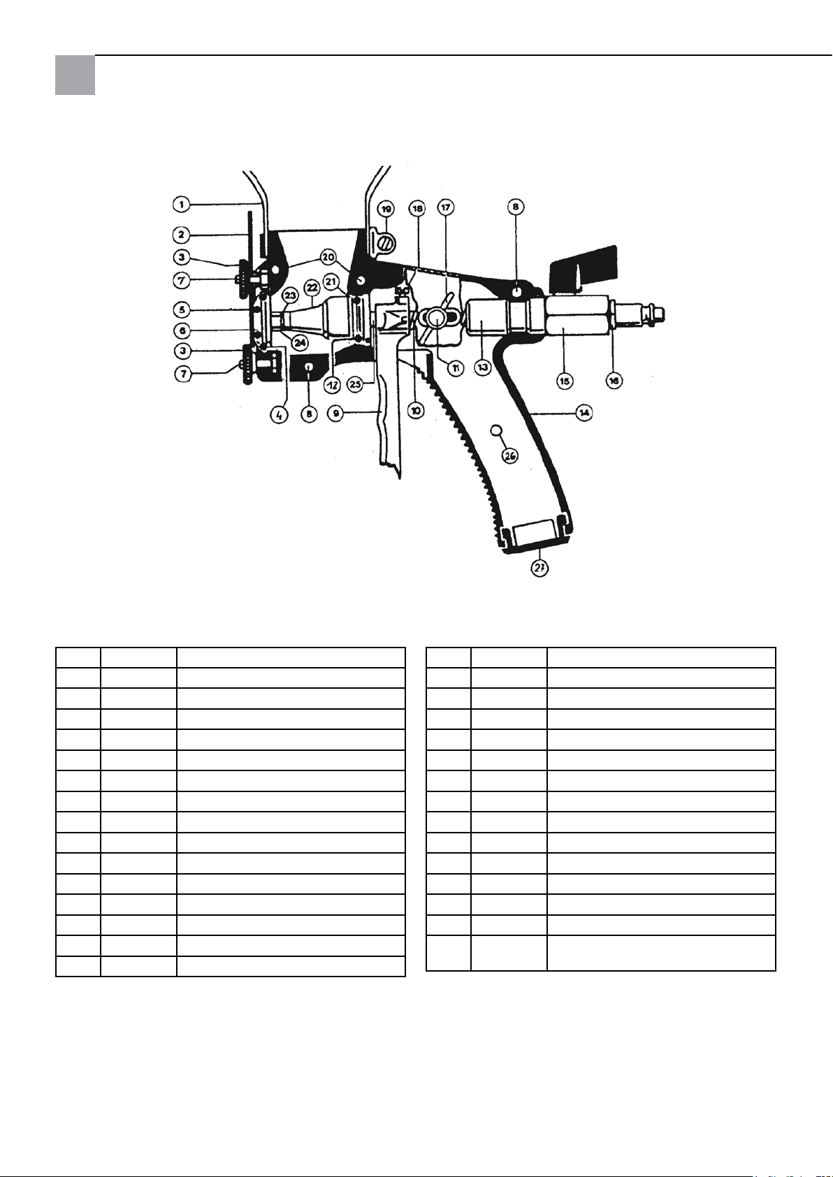
Disegno dettagli
Elenco dei pezzi di ricambio
Pos. N. art. Descrizione
1 63 18 51 Imbuto
2 63 18 52 Disco degli ugelli a 9 fori
3 63 18 56 Dado zigrinato
4 63 18 95 Guarnizione circolare
5 63 18 80 Guarnizione circolare
6 63 18 89 Ugello per materiale
7 63 18 44 Vite M 5 x 14
8 63 18 36 Vite M 5 x 14
9 63 18 65 Leva di scatto lunga
10 63 18 69 Molla di compressione
11 63 18 45 Vite M 6 x 16
12 63 18 97 Guarnizione circolare
13 63 18 98 Guida principale
14 63 18 83 Corpo pistola destra
63 18 84 Corpo pistola sinistra
Pos. N. art. Descrizione
15 63 18 93 Rubinetto a sfera
16 60 39 09 Nipplo ad innesto 1/4“ AG
17 63 18 46 Dado ad alette M 6
18 63 18 48 Vite M 5 x 8
19 63 18 81 Fascetta di ssaggio
20 63 18 34 Vite M 5 x 22
21 63 18 96 Guida tubo aria
22 63 18 60 Membrana
23 63 18 47 Anello di rame
24 63 18 59 Ugello aria
25 63 18 64 Tubo aria
26 63 18 35 Vite M 5 x 10
27 63 18 88 Fondo impugnatura
s. g.
63 18 03 Piede di appoggio con fascetta di
ssaggio
16
Page 17

Garanzia
Condizioni di garanzia:
Per i nostri apparecchi sono applicabili dei periodi di garanzia di 12 mesi a partire dalla data di acquisto / data della
fattura del cliente finale commerciale. Se da parte nostra vengono accordati dei periodi di garanzia più estesi, ciò sarà
riportato separatamente nelle istruzioni per l‘uso inerenti ai rispettivi dispositivi.
Rivendicazioni:
In casi in cui si intende far valere il diritto di garanzia, vi preghiamo di inviarci il dispositivo in modo completo con fattura, franco nostro centro di logistica a Berka oppure ad una service-station da noi autorizzata.
Si prega di consultare prima la Hotline di servizio STORCH a pagamento: 02 - 66 22 77 15
Diritto alla garanzia
Il diritti si possono far valere solo per errori di materiale o di produzione nonché esclusivamente in caso di utilizzo
appropriato dell'apparecchio. Componenti soggetti a logorio non vengono contemplate da tale diritto. Decadranno tutti
i diritti di garanzia con l'aggiunta delle componenti di terzi, maneggio e magazzinaggio non appropriato come anche in
casi di ovvia non osservanza delle istruzioni per l'uso.
Esecuzione di riparazioni
Ogni intervento di riparazione va eseguito esclusivamente nei nostri stabilimenti o presso una service-station autorizzata STORCH.
17
Page 18

GB
Thank you
for your confidence in STORCH. You have chosen a quality product with this purchase.
If you would like to suggest an improvement, or experience a problem with your product, please do not hesitate to
contact us.
Please speak to your area representative, or in urgent cases, please contact us directly.
Yours sincerely,
STORCH Service Department
Tel: +49 (0)2 02 . 49 20 - 112
Fax: +49 (0)2 02 . 49 20 - 244
Free service hotline: 08 00. 7 86 72 47
Free order hotline: 08 00. 7 86 72 44
Toll-free order fax: 08 00. 7 86 72 43
(only available in Germany)
Table of contents Page
Scope of delivery 18
Processable materials 18
Changing the nozzle orifice 19
Adjusting the air flow 19
Consistency of the mixed material 19
Adjusting the supply of material 19
Cleaning the device 19
Detailed drawing 20
Spare parts list 20
Warranty 21
Scope of delivery
Plaster gun, hopper, stand with mounting bracket, instruction manual.
Processable materials
Decorative finishing plaster, liquid wood chip, reinforcing adhesive, plastic materials, quartz sand plaster up to 6 mm,
dry quartz up to 8 mm, fibrous plaster, etc.
18
Page 19

1. Changing the nozzle orifice
To ensure a good texture you should select a nozzle orifice that is at least double the diameter of the largest plaster
grain.
To do this, loosen the two knurled nuts (3). When the trigger is actuated the nozzle disc (2) can be easily rotated to the
desired position (4 - 13 mm diameter holes).
Make sure the sealing ring (5) is applied cleanly behind the nozzle disc. The nozzle is centred over the hole by releasing
the trigger. The upper knurled nut can then be retightened, followed by the lower nut.
2. Adjusting the air flow
The amount of air required by the plaster gun is approximately 220 l / min. A working pressure of 2 - 3 bar is generally
sufficient for all spray applications.
The amount of air can be easily adjusted via the high-pressure valve on the plaster gun. The more air you select, the
finer the spray pattern will be. If you work with too much air, it can cause the individual grains of sand to be separated
from the binding agent and rebound from the wall. This results in loss of material and contamination.
3. Consistency of the mixed material
An important prerequisite for reliable operation is the use of evenly mixed material that is free of any coarse impurities.
It is necessary to keep the plaster thick enough so that it just slides down into the hopper gun. The plaster droplets
then remain on the processed surface and form a beautiful texture.
A common misconception, however, is to thin the plaster if you want a finer texture. In this case, it is far better to use
a smaller nozzle or to select a higher volume of air.
4. Adjusting the supply of material
A thumb screw is located at the side of the handle, which can be used to adjust and lock the amount of material that
is required. As a rule of thumb, please note that the distance between the air nozzle (24) and the material nozzle (6)
must be slightly larger than the selected nozzle hole. You can check this distance by unscrewing the nozzle disc (2).
You will quickly determine the correct volume of material and settings for your hopper gun.
5. Cleaning the device
Please wash thoroughly with water, blow through the nozzle orifice and clean the exterior of the gun on a regular basis.
Caring for your device and keeping it clean will ensure reliable operation.
19
Page 20
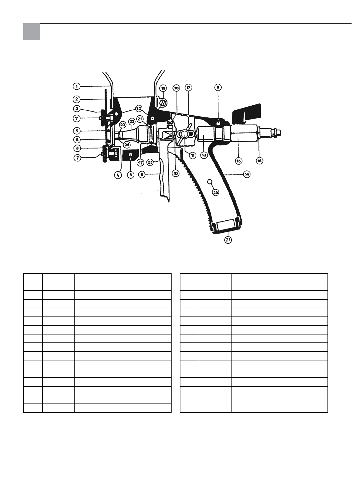
Detailed drawing
List of spare parts
Pos. Art. no. Designation
1 63 18 51 Hopper
2 63 18 52 9-hole nozzle disc
3 63 18 56 Knurled nut
4 63 18 95 O-ring
5 63 18 80 O-ring
6 63 18 89 Fluid Nozzle
7 63 18 44 M5x14 Screw
8 63 18 36 M5x14 Screw
9 63 18 65 Trigger, long
10 63 18 69 Pressure spring
11 63 18 45 M6x16 Screw
12 63 18 97 O-ring
13 63 18 98 Main guide
14 63 18 83 Gun body, right
63 18 84 Gun body, left
Pos. Art. no. Designation
15 63 18 93 Ball valve
16 60 39 09 Plug-in nipple 1/4" OT
17 63 18 46 Wing nut M6
18 63 18 48 M5x8 screw
19 63 18 81 Mounting bracket
20 63 18 34 M5x22 Screw
21 63 18 96 Air pipe guide
22 63 18 60 Membranes
23 63 18 47 Copper ring
24 63 18 59 Air nozzle
25 63 18 64 Air pipe
26 63 18 35 M5x10 screw
27 63 18 88 Handle seal
Not
63 18 03 Stand with mounting bracket
illus-
trated
20
Page 21

Warranty
Warranty conditions:
A warranty period of twelve months from the date of purchase/date of invoice applies to our tools for commercial
customers. If we have granted an extended warranty period, this period will be noted separately in the operating manual for the equipment in question.
Claims:
If you wish to claim under our warranty or guarantee, please return the complete device and your invoice to our logistics centre in Berka, postage paid, or send it to one of our authorised service centres.
Please contact the chargeable STORCH service hotline first: +49 (0)202 . 49 20 – 110.
Your rights under our warranty or guarantee
Claims can only be accepted for material defects or manufacturing errors, and only assuming intended use of the appliance. Wear parts are not covered by such claims. All claims shall become void in the event of installation of third party
components, improper handling and storage, as well as in the event of obvious disregard of the operating instructions.
Repairs
All repairs have to be conducted on our premises or by an authorised STORCH service centre.
21
Page 22

CZ
Děkujeme Vám
za důvěru ve firmu STORCH. S nákupem výrobku jste se rozhodli pro kvalitní produkt.
Pokud přesto máte podněty na zlepšení nebo možná nějaký problém, velmi rádi o Vás uslyšíme.
Promluvte si s příslušným externím spolupracovníkem naší firmy nebo se v naléhavých případech obracejte přímo na
nás.
S přátelským pozdravem
Servisní oddělení STORCH
Telefon: +49 (0)2 02 . 49 20 - 112
Fax: +49 (0)2 02 . 49 20 - 244
bezplatná linka Hotline - servis: +49 800. 7 86 72 47
bezplatná linka Hotline - objednávky: +49 800. 7 86 72 44
bezplatný fax - objednávky: +49 800. 7 86 72 43
(pouze v Německu)
Obsah Strana
Rozsah dodávky 22
Zpracovatelné materiály 22
Změna nastavení otvoru trysky 23
Nastavení množství vzduchu 23
Konzistence směsi materiálu 23
Nastavení přívodu materiálu 23
Čištění přístroje 23
Podrobný výkres 24
Seznam náhradních dílů 24
Záruka 25
Rozsah dodávky
Omítací pistole, trychtýř, stojan s příchytkou, návod k obsluze.
Zpracovatelné materiály
Dekorativní vrchní omítky, tekutá hrubá vlákna, armovací lepidla, syntetické hmoty, omítka s křemičitým pískem do 6
mm, suchá křemenná drť do 8 mm, omítka s vlákny a mnoho dalších materiálů.
22
Page 23

1. Změna nastavení otvoru trysky
Pro dobrou strukturu materiálu byste měli zvolit minimálně dvojnásobný průměr než jaký mají největší zrna malty.
Povolte k tomu účelu obě rýhované matice (3). Při natažené spoušti lze kotoučem s tryskami (2) s vyvrtanými otvory o
průměru 4 - 13 mm snadno otočit do požadované polohy nastavení.
Dbejte na to, aby těsnící kroužek (5) čistě doléhal za kotoučem s tryskami. Povolením spouště se tryska vycentruje k
vyvrtanému otvoru. Následně lze opět dotáhnout horní a potom spodní rýhovanou matici.
2. Nastavení množství vzduchu
Potřeba vzduchu omítací pistole je kolem cca 220 l / min. Pracovní tlak 2 - 3 bary zpravidla stačí pro veškeré práce při
aplikaci stříkáním.
Množství vzduchu lze snadno nastavit vysokotlakým kohoutem na omítací pistoli. Čím více vzduchu jste nastavili, tím
jemnější bude struktura aplikovaného nástřiku. Když pracujete s příliš velkým množstvím vzduchu, mohou se zrnka písku oddělit od pojiva a odrážet se zpět od stěny. To vede ke ztrátě materiálu a znečištění.
3. Konzistence směsi materiálu
Důležitým předpokladem pro spolehlivou práci je použití rovnoměrně namíchaného materiálu, který neobsahuje žádné
hrubé znečištění. Je třeba, aby malta byla tak hustá, aby v trychtýři pistole ještě dobře sklouzla. Kapičky malty potom
dobře drží na omítané ploše a vytvoří hezkou strukturu.
Je však většinou špatně namíchat maltu řidší, když je požadována jemnější struktura. V tomto případě je lepší nastavit
menší trysku nebo vyšší množství vzduchu.
4. Nastavení přívodu materiálu
Na straně držadla pistole je umístěn křídlatý šroub, čímž můžete průběžně nastavovat a aretovat množství materiálu, který je třeba. Respektujte prosím jako základní pravidlo, že vzdálenost mezi vzduchovou tryskou (24) a tryskou k vedení materiálu (6) musí být o něco větší než zvolený otvor trysky. Tuto vzdálenost lze překontrolovat při
našroubovaném kotouči s tryskami (2).
Během krátké doby zjistíte, kolik materiálu a jaké nastavení trychtýře pistole je správné pro Vaši práci.
5. Čištění přístroje
Části přístroje je třeba pravidelně a důkladně vymýt vodou, otvor trysek profouknout a očistit z vnější strany.
Tato péče a čistění přístroje se navrátí v podobě spolehlivého fungování přístroje.
23
Page 24
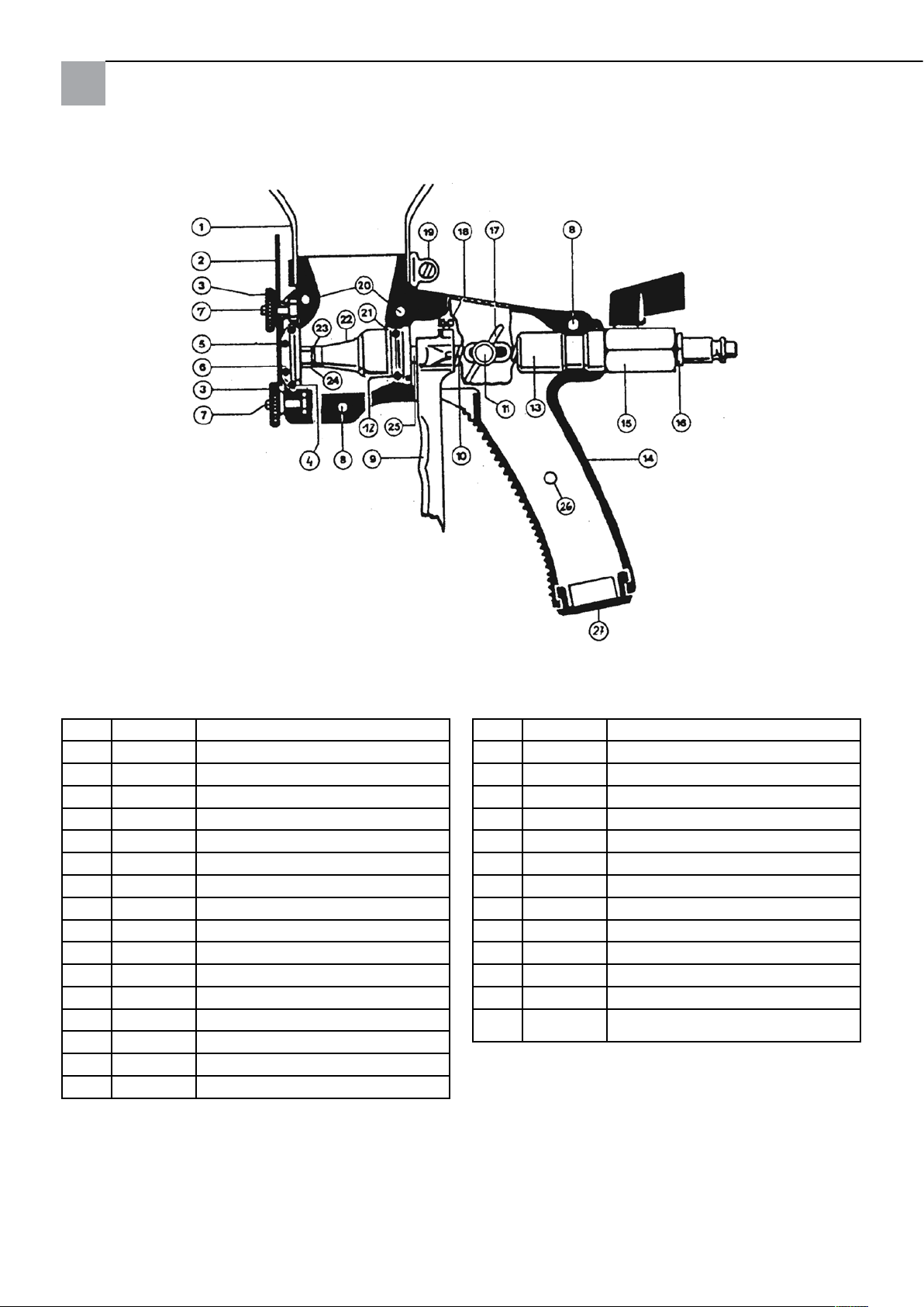
Podrobný výkres
Seznam náhradních dílů
Pol. Obj.č. Název
1 63 18 51 Trychtýř
2 63 18 52 9-otvorový kotouč s tryskami
3 63 18 56 Rýhovaná matice
4 63 18 95 O-kroužek
5 63 18 80 O-kroužek
6 63 18 89 Tryska na materiál
7 63 18 44 Šroub M 5 x 14
8 63 18 36 Šroub M 5 x 14
9 63 18 65 Spoušť dlouhá
10 63 18 69 Přítlačná pružina
11 63 18 45 Šroub M 6 x 16
12 63 18 97 O-kroužek
13 63 18 98 Hlavní vedení
14 63 18 83 Těleso pistole vpravo
63 18 84 Těleso pistole vlevo
Pol. Obj.č. Název
15 63 18 93 Kulový kohout
16 60 39 09 Zásuvné šroubení 1/4“ AG
17 63 18 46 Křídlatá matice M 6
18 63 18 48 Šroub M 5 x 8
19 63 18 81 Příchytka
20 63 18 34 Šroub M 5 x 22
21 63 18 96 Vedení vzduchové trubice
22 63 18 60 Membrána
23 63 18 47 Měděný kroužek
24 63 18 59 Vzduchová tryska
25 63 18 64 Vzduchová trubice
26 63 18 35 Šroub M 5 x 10
27 63 18 88 Uzávěr s držadlem
bez
63 18 03 Stojan s příchytkou
obr.
24
Page 25

Záruka
Záruční podmínky:
U našich zařízení platí zákonné záruční lhůty 12 měsíců od data zakoupení/data faktury obchodního konečného zákazníka. Pokud jsou delší lhůty v cestě námi vypsanému prohlášení o záruce, jsou zvláště vyznačeny v návodu k obsluze
příslušných zařízení.
Uplatňování:
V případě záručního příp. garančního případu žádáme, aby bylo zasláno kompletní zařízení dohromady s fakturou do
našeho střediska Logisitk Center v Berka nebo do námi autorizované servisní stanice.
Kontaktujte prosím nejdříve placený hotline servis firmy STORCH: +49 (0)202 . 49 20 – 110.
Nárok na záruku příp. garanci
Nároky na záruku existují výhradně u materiálu nebo výrobní vady a také výhradně při používání přístroje v souladu s
určeným účelem. Díly podléhající opotřebení nespadají do takovýchto nároků. Veškeré nároky zanikají zamontováním
dílů cizího původu, při nepřiměřeném zacházení a skladování a také při zřejmém nedodržování provozního návodu.
Provádění oprav
Veškeré opravy smí být prováděny výhradně naším závodem nebo servisními stanicemi autorizovanými společností
STORCH.
25
Page 26

262728
Page 27

Page 28

Art.-Nr. Bezeichnung
63 18 01 Putzpistole
Art.-nr. Omschrijving
63 18 01 Pistool voor pleisters
ART. No. Désignation
63 18 01 Pistolet à enduire
N. art. Descrizione
63 18 01 Pistola per intonaco
Item no. Description
63 18 01 Plaster gun
Výr. č. Označení
63 18 01 Omítací pistole
Malerwerkzeuge & Profigeräte GmbH
Platz der Republik 6 - 8
D-42107 Wuppertal
Telefon: +49 (0)2 02 . 49 20 - 0
Telefax: +49 (0)2 02 . 49 20 - 111
E-mail: [email protected]
H 002098
Internet: www.storch.de
12-2012
 Loading...