

Page 1
1
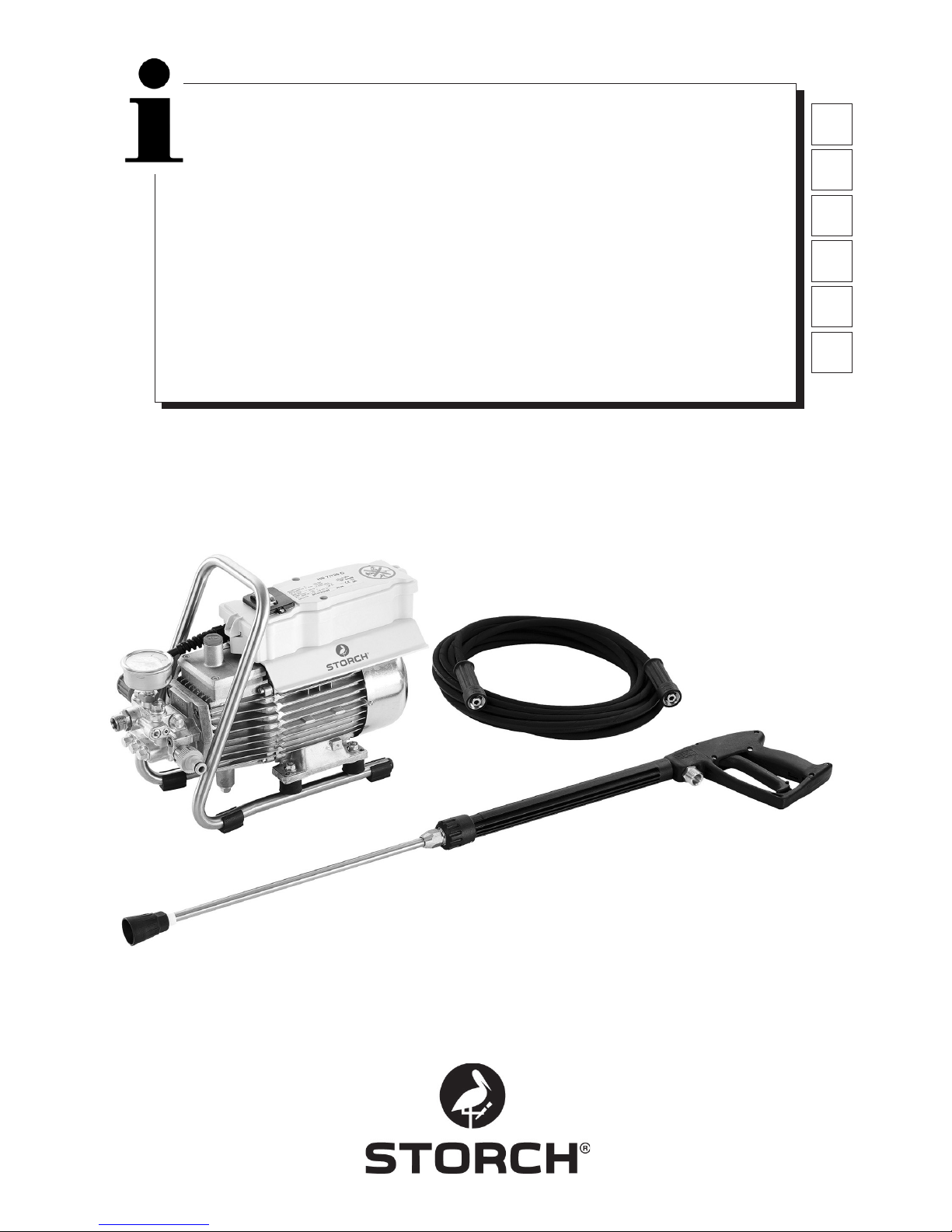
Hochdruckreiniger 120 Compact ab 08.2013
Hogedrukreiniger 120 Compact vanaf 08.2013
Nettoyeur haute pression 120 compact à partir de 08.2013
Idropulitrice ad alta pressione 120 Compact
a partire dall 08.2013
High pressure cleaner 120 Compact from 08.2013
Vysokotlaké čistící zařízení 120 Compact od data 08.2013
DE
NL
FR
IT
GB
CZ
Page 2

2
DE
Vielen Dank
für Ihr Vertrauen zu STORCH. Mit dem Kauf haben Sie sich für ein Qualitäts-Produkt entschieden.
Haben Sie trotzdem Anregungen zur Verbesserung oder aber vielleicht einmal ein Problem, so freuen wir uns sehr, von
Ihnen zu hören.
Bitte sprechen Sie mit Ihrem Außendienst-Mitarbeiter oder in dringenden Fällen auch mit uns direkt.
Mit freundlichen Grüßen
STORCH Service Abteilung
Telefon: +49 (0)2 02 . 49 20 - 112
Fax: +49 (0)2 02 . 49 20 - 244
kostenlose Service-Hotline: 08 00. 7 86 72 47
kostenlose Bestell-Hotline: 08 00. 7 86 72 44
kostenloses Bestell-Fax: 08 00. 7 86 72 43
(nur innerhalb Deutschlands)
Inhaltsverzeichnis Seite
1. Technische Daten 3
2. Gerätebeschreibung / Funktion 3
3. Wasser- und Reinigungs-Pflegemittelsystem 3
4. Spritzpistole mit Waschlanze 4
5. Druckregel-Sicherheitsventil 4
6. Aufstellung: Standort 4
7. Kurzbetriebsanleitung 5
8. Inbetriebnahme 5
9. Druckeinstellung 6
10. Außerbetriebnahme 6
11. Sicherheitshinweise 6
12. Hilfe bei der Beseitigung von Störungen 7 - 8
13. Ersatzteillisten 8 - 11
14. Prüfungen 12
15. Garantie / Garantiebedingungen 12
16. EG- Konformitätserklärung 13
Lieferumfang
Hochdruckreiniger, Hochdruckschlauch 10 m, Waschlanze, Bedienungsanleitung.
Page 3
3
Technische Daten
Arbeitsdruck, stufenlos regelbar 10 - 120 bar
Zulässiger Überdruck 135 bar
Wasserleistung 10 l / min bei 2.800 U / min
Warmwasserzulauf bis 60° C
Ansaughöhe 1 m
Hochdruckschlauch 10 m
Elektrischer Anschlußwert 230 V / 50 Hz, 11 A
elektrische Leistung 2.500 W
Gewicht (ohne Zubehör) 18,5 kg
Düsengröße 20042
Schallleistungspegel gemessen: 71 dB (A)
garantiert: 91 dB (A)
Rückstoß an der Lanze ca. 27 N
Vibrationen an der Lanze 1,9 m/s
2
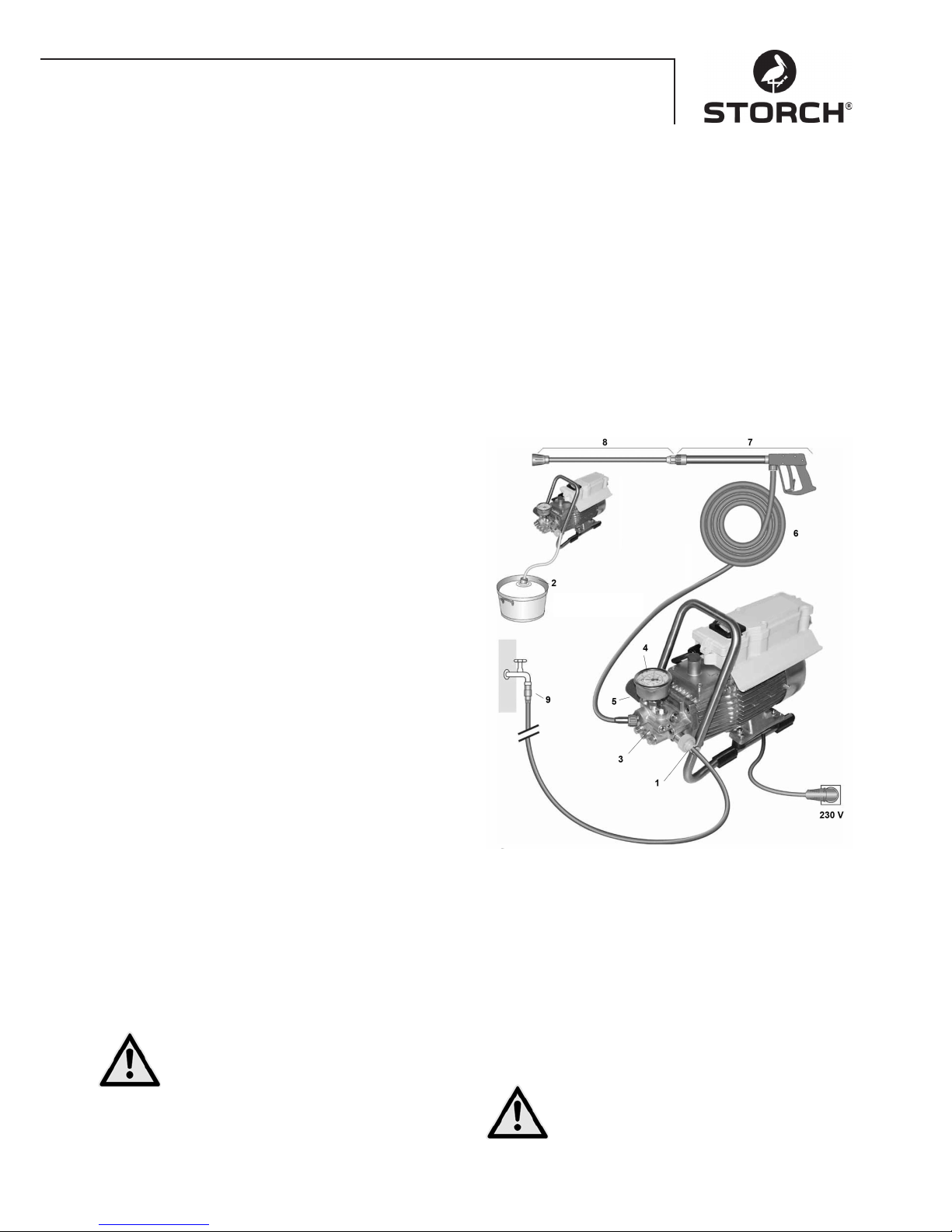
Gerätebeschreibung / Funktion
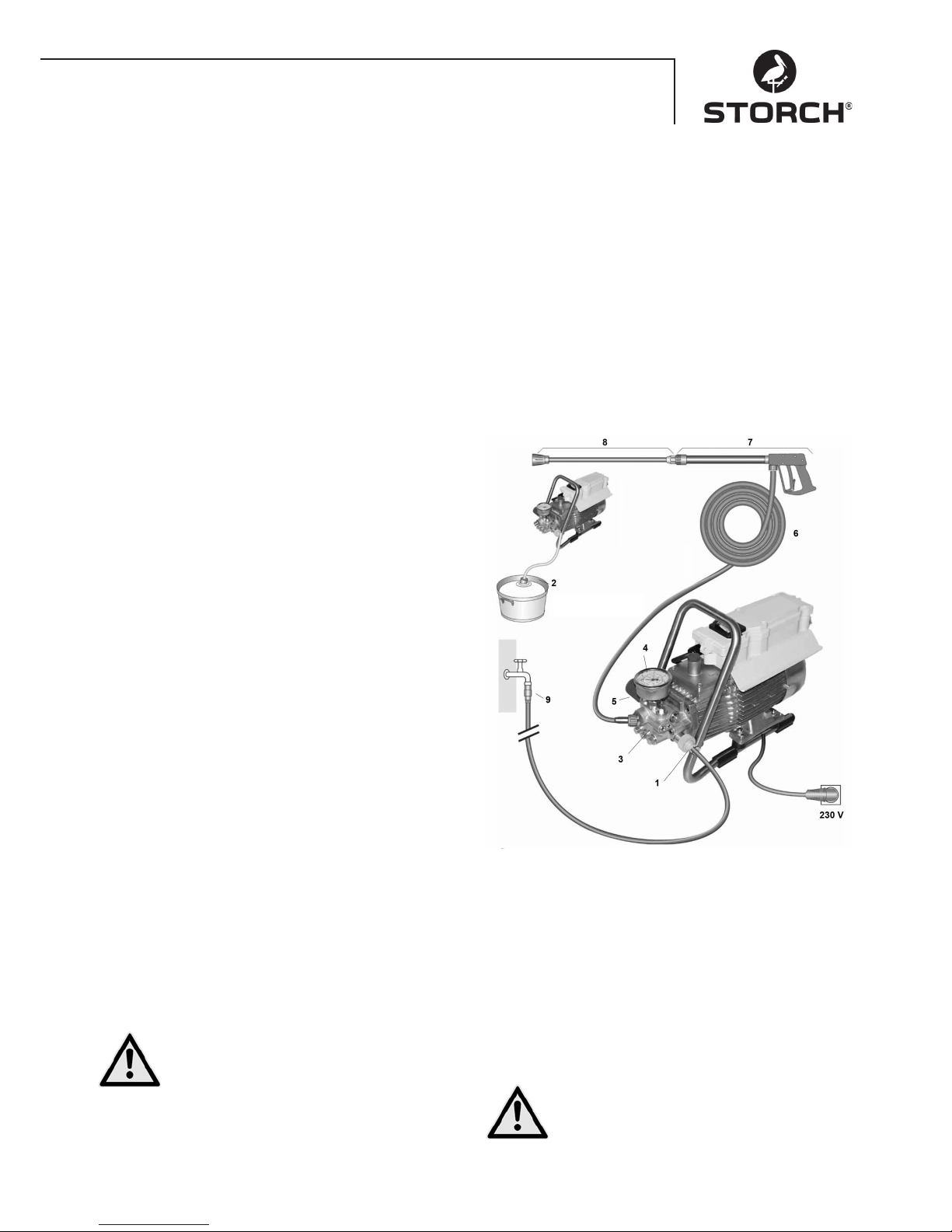
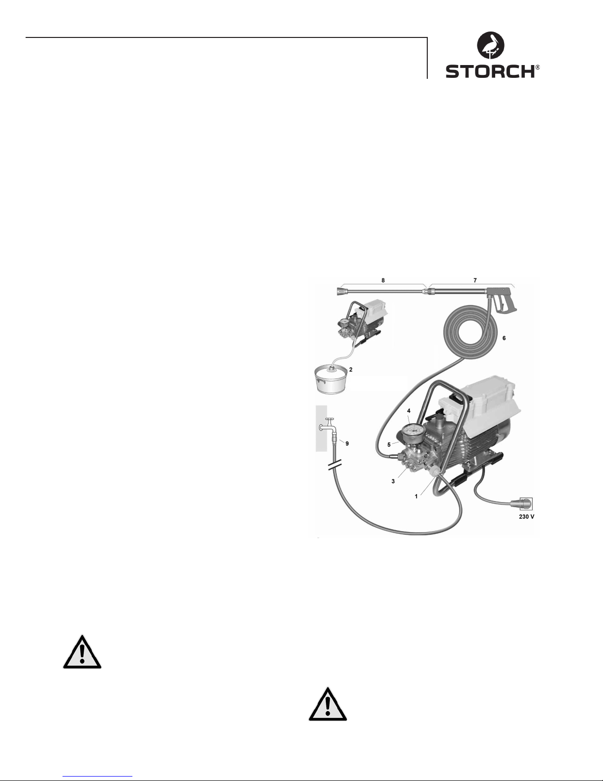
1 Zulauf Wasseranschluß mit Filter
2 Ansaugschlauch mit Filterkorb (Sonderzubehör)
3 Hochdruckpumpe
4 Manometer
5 Druckregelventil-Sicherheitsventil
6 Hochdruckschlauch
7 Spritzpistole
8 Waschlanze
Wasser
Wasser- und Reinigungs- /
Pflegemittelsystem
Das Wasser kann unter Druck der Hochdruckpumpe zugeführt oder direkt aus einem drucklosen Behälter angesaugt werden. Anschließend wird das Wasser von der
Hochdruckpumpe unter Druck der Waschlanze zugeführt.
Durch die Düse an der Waschlanze wird der Hochdruckstrahl gebildet.
Spritzpistole mit Waschlanze
Die Spritzpistole ermöglicht den Betrieb der Maschine nur
bei betätigtem Sicherheitsschalthebel.
Durch Betätigen des Hebels wird die Spritzpistole geöffnet. Das Wasser wird dann zur Düse gefördert. Der
Spritzdruck baut sich auf und erreicht schnell den gewählten Arbeitsdruck.
Durch Loslassen des Schalthebels wird die Pistole
geschlossen und weiterer Austritt von Wasser aus der
Waschlanze verhindert. Der Druckstoß beim Schließen
der Pistole öffnet das Druckregelventil-Sicherheitsventil
und die Pumpe fördert mit dem gewählten Arbeitsdruck
zur Waschlanze.
Die Spritzpistole ist eine Sicherheitseinrichtung Reparaturen dürfen nur von Sachkundigen vorgenommen werden. Bei Ersatzbedarf
sind nur vom Hersteller zugelassene Bauteile
zu verwenden.
Druckregel-Sicherheitsventil
Das Druckregelventil-Sicherheitsventil schützt die
Maschine vor unzulässig hohem Überdruck und ist so
gebaut, daß es nicht über den zulässigen Betriebsdruck
hinaus eingestellt werden kann. Die Begrenzungsmutter
des Drehgriffes ist mit Lack versiegelt.
Durch Betätigen des Drehgriffes können der Arbeitsdruck
und die Spritzmenge stufenlos eingestellt werden.
Austausch, Reparaturen, Neueinstellungen
und Versiegelungen dürfen nur von Sachkundigen vorgenommen werden.
Page 4
4
Wasseranschluss
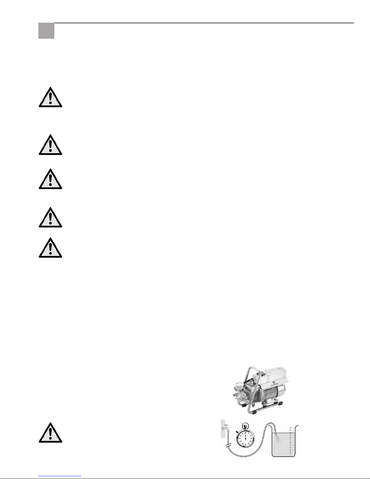
Bitte prüfen Sie, ob dem Hochdruckreiniger die auf Seite 3 (Technische Daten) angegebene Wassermenge (Liter
pro Minute) zur Verfügung steht.
Prüfung: Wasserzuführungsschlauch 1 Minute in einen
Eimer laufen lassen. Die Wassermenge muß mindestens
der Angabe auf Seite 3 entsprechen !
Wassermangel führt zum schnellen Verschleiß
der Dichtung (keine Garantie).
Motorschutzschalter
Der Motor wird durch einen Motorschutzschalter vor Überlastung geschützt. Bei Überlastung schaltet der Motorschutzschalter den Motor ab. Bei wiederholtem Abschalten des Motors durch den Motorschutzschalter Störungsursache beseitigen (siehe Seite 7/8).
Austausch und Prüfarbeiten dürfen nur von Sachkundigen bei vom elektrischen Netz getrennter Maschine,
d.h. bei gezogenem Netzstecker, vorgenommen werden.
Aufstellung
Standort
Die Maschine darf nicht in feuer- und explosionsgefährdeten Räumen sowie in Pfützen aufgestellt und
betrieben werden. Das Gerät darf nicht unter Wasser betrieben werden.
ACHTUNG:
Niemals lösungsmittelhaltige Flüssigkeiten wie Lackverdünnungen, Benzin, Öl oder ähnliche Flüssigkeiten
ansaugen. Angaben der Zusatzmittel-Merkblätter beachten. Die Dichtungen im Gerät sind nicht lösungsmittelbständig! Der Sprühnebel von Lösungsmitteln ist hochentzündlich, explosionsfähig und giftig.
ACHTUNG:
Bei Betrieb mit 60°C Warmwasser treten erhöhte Temperaturen auf.
Gerät nicht ohne Schutzhandschuhe anfassen.
Elektroanschluss
Die Maschine wird mit einem 5 m Anschlußkabel mit Netzstecker geliefert. Der Stecker muß in eine vorschriftsmäßig installierte Steckdose mit Schutzleiteranschluß und FI-Fehlerstrom-Schutzschalter 30 mA eingesteckt werden. Die Steckdose ist netzseitig mit 16 A träge abzusichern.
Bei Verwendung eines Verlängerungskabels muß dieses einen Schutzleiter haben, der vorschriftsgemäß an den Steckverbindungen angeschlossen ist. Die Leiter des Verlängerungskabels müssen einen Mindestquerschnitt von 2,5 mm²
haben. Die Steckverbindungen müssen eine spritzwassergeschützte Ausführung sein und dürfen nicht auf nassem
Boden liegen.
Elektropassus
Das Gerät besitzt einen Spannungsbereich, von dem eine elektrische Gefahr für Mensch und Tier ausgehen kann. Es
darf nur von autorisierten Personen aufgeschraubt und / oder demontiert werden.
Ebenso dürfen Instandhaltungsarbeiten und Reparaturen nur von STORCH oder von STORCH autorisierten Service-Stationen ausgeführt werden. Der Betrieb des Gerätes geschieht auf eigene Verantwortung und Gefahr des Anwenders.
Page 5

5
Kurzbetriebsanleitung
Gerät nur waagerecht betreiben!
1. Hochdruckschlauch mit Spritzpistole und Gerät verschrauben.
2. Saugseitigen Wasseranschluß herstellen.
3. Gerät entlüften (Spritzpistole mehrmals öffnen und schließen).
4. Stromanschluß herstellen.
5. Gerät bei geöffneter Spritzpistole einschalten und mit dem Waschvorgang beginnen.
6. Nach Beendigung des Waschvorgangs Pumpe vollständig entleeren (ohne Saug- und Druckschlauch ca. 20 Sek. den
Motor einschalten).
- Nur sauberes Wasser verwenden!
- Vor Frost schützen!
ACHTUNG:
Beachten Sie die Vorschriften Ihres Wasserversorgungsunternehmens. Die Maschine darf nach EN 61770 nicht unmittelbar an die öffentliche Trinkwasserversorgung angeschlossen werden.
Der kurzzeitige Anschluß ist nach DVGW (Deutscher Verband des Gas- und Wasserfachs) jedoch zulässig, wenn ein
Rückflußverhinderer mit Rohrbelüfter in die Zuleitung eingebaut ist.
Auch ein mittelbarer Anschluß an die öffentliche Trinkwasserversorgung ist zulässig mittels eines freien Auslaufes nach
EN 61770, z.B. durch den Einsatz eines Behälters mit Schwimmerventil.
Ein unmittelbarer Anschluß an ein nicht für die Trinkwasserversorgung bestimmtes Leitungsnetz ist zulässig.
Hochdruckschlauchleitung und Spritzeinrichtung
Die zur Ausstattung der Maschine gehörende Hochdruckschlauchleitung und Spritzeinrichtung bestehen aus hochwertigem Material und sind auf die Betriebsbedingungen der Maschine abgestimmt sowie vorschriftsmäßig gekennzeichnet. Maximale Wasserzuleitung 20 m.
Bei Ersatzbedarf sind nur vom Hersteller zugelassene und vorschriftsgemäß gekennzeichnete Bauteile zu
verwenden. Hochdruckschlauchleitungen und Spritzeinrichtungen sind druckdicht anzuschließen. Die Hochdruckschlauchleitung darf nicht überfahren, übermäßig gezogen oder verdreht werden. Die Hochdruckschlauchleitung darf nicht über scharfe Kanten gezogen werden, sonst erlischt die Garantie.
Wasser
Inbetriebnahme
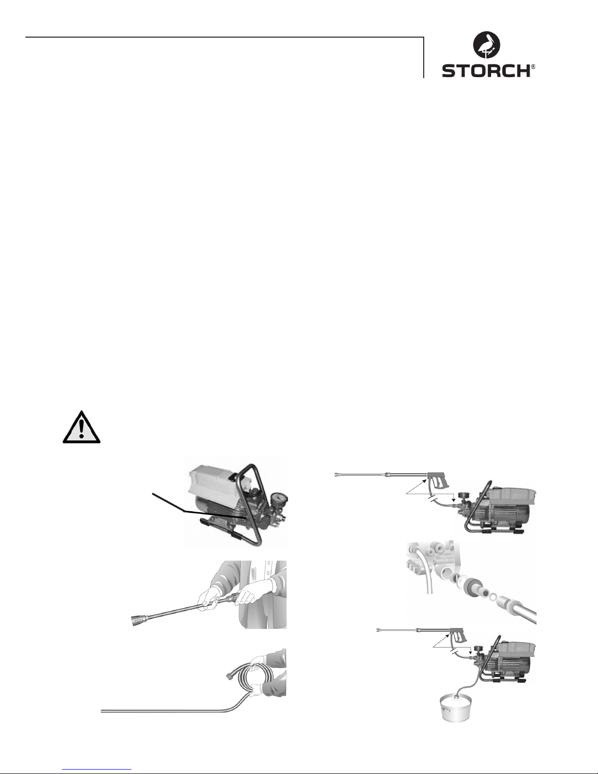
1.
Ölstand kontrollieren
Öl muß im Schauglas
sichtbar sein
2.
Hochdrucklanze mit der
Handpistole verbinden
3.
Hochdruckschlauch schlingenfrei abrollen
und mit der Handpistole um Pumpe
verbinden. Bei Verlängerung max.
20 m HD-Schlauch verwenden oder
2 x 10 m mit Schlauchverbindungen.
Verbindung vom
Hochdruckschlauch
zur Lanze.
4.
Die Maschine kann
wahlweise an die
Druckwasserleitung
mit kaltem oder bis zu
60° C heißem Wasser
angeschlossen werden.
Beim Außenansaugen auf
sauberes Wasser achten.
Hinweis:
Wassereingangsfilter
Art.-Nr. 65 65 60 verwenden.
Der Schlauchquerschnitt muß
mindestens 1/2“ = 12,7 mm sein
(freier Durchgang). Sieb Nr. 1 muß
immer sauber sein.
5.
Maximale Ansaughöhe 1,0 m
- siehe Technische Daten Seite 3.
Page 6
6
Druckverstellung
Durch Verdrehen des Handrades. Maximaler Druck ist
voreingestellt.
Außerbetriebnahme
1. Gerät abschalten
2. Wasserzufuhr sperren
3. Pistole kurz öffnen, bis der Druck abgebaut ist
4. Pistole verriegeln
5. Wasserschlauch und Hochdruckschlauch abschrauben
6. Pumpe entleeren: Motor ca. 20 Sekunden einschalten
7. Netzstecker ziehen
8. Winter: Pumpe in frostfreien Räumen lagern
9. Wasserfilter reinigen
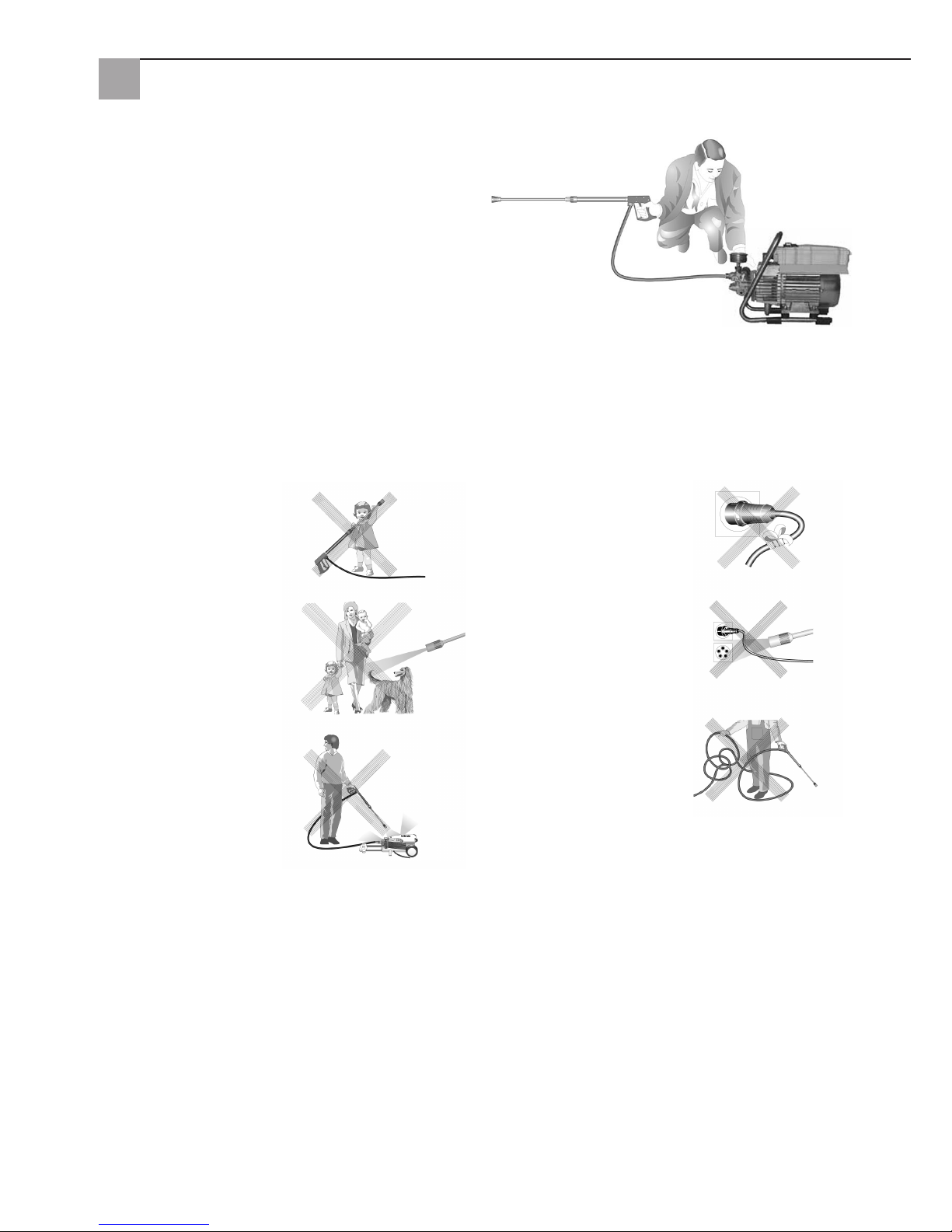
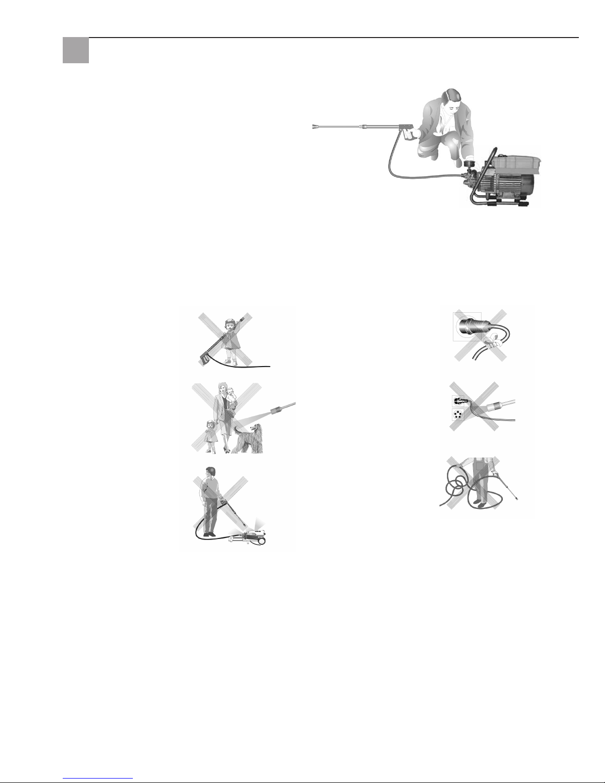
Das ist verboten !
Kinder dürfen nicht mit
Hochdruckreinigern arbeiten!
Den Wasserstrahl nie
auf Menschen oder
Tiere richten!
Das Gerät nicht mit
Hochdruck oder Wasserstrahl
absprühen!
Das Kabel nicht beschädigen
oder unsachgemäß reparieren!
Den Wasserstrahl nicht
auf Steckdosen richten!
HD-Schlauch nicht mit
Schlingen oder Knick ziehen!
Schlauch nicht über
scharfe Kanten ziehen!
Page 7
7
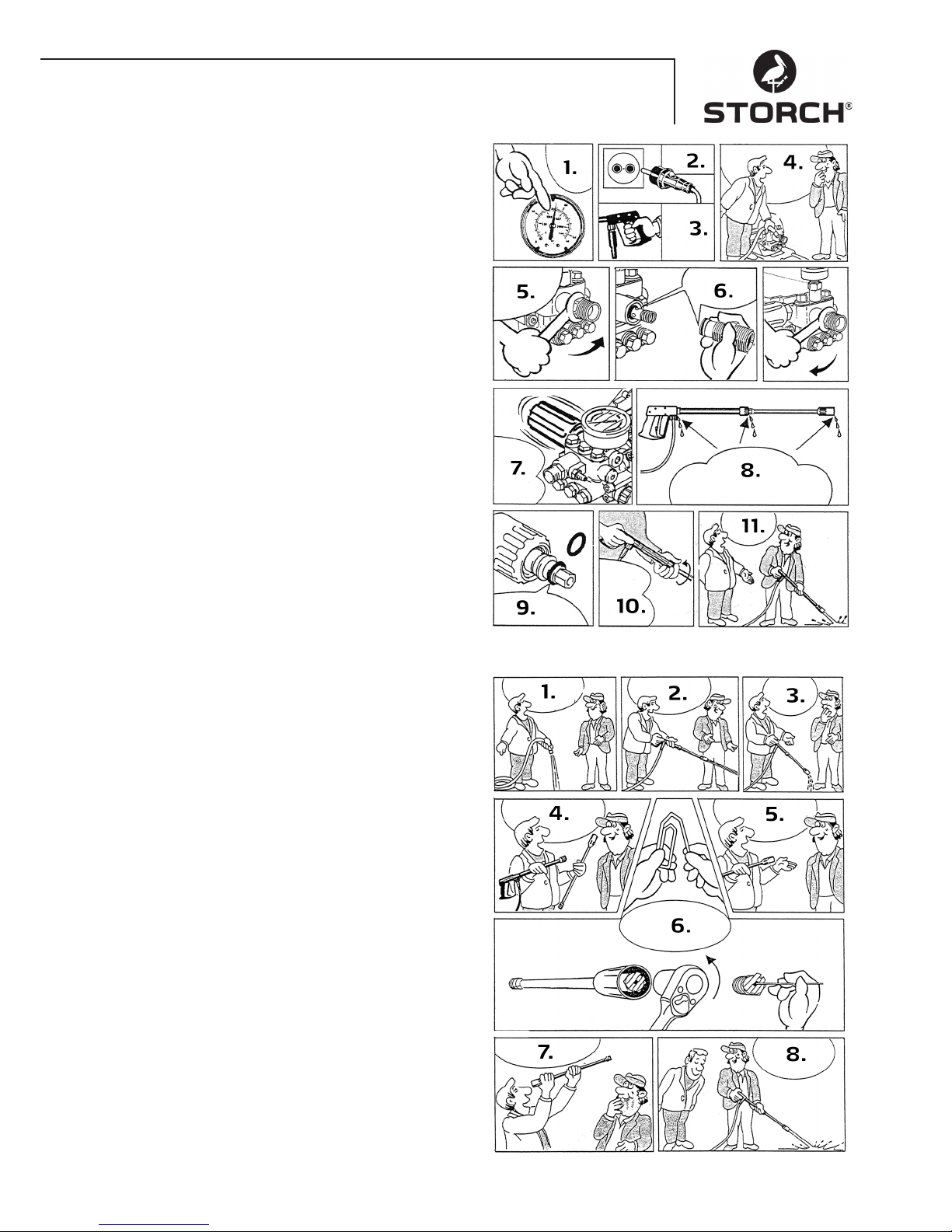
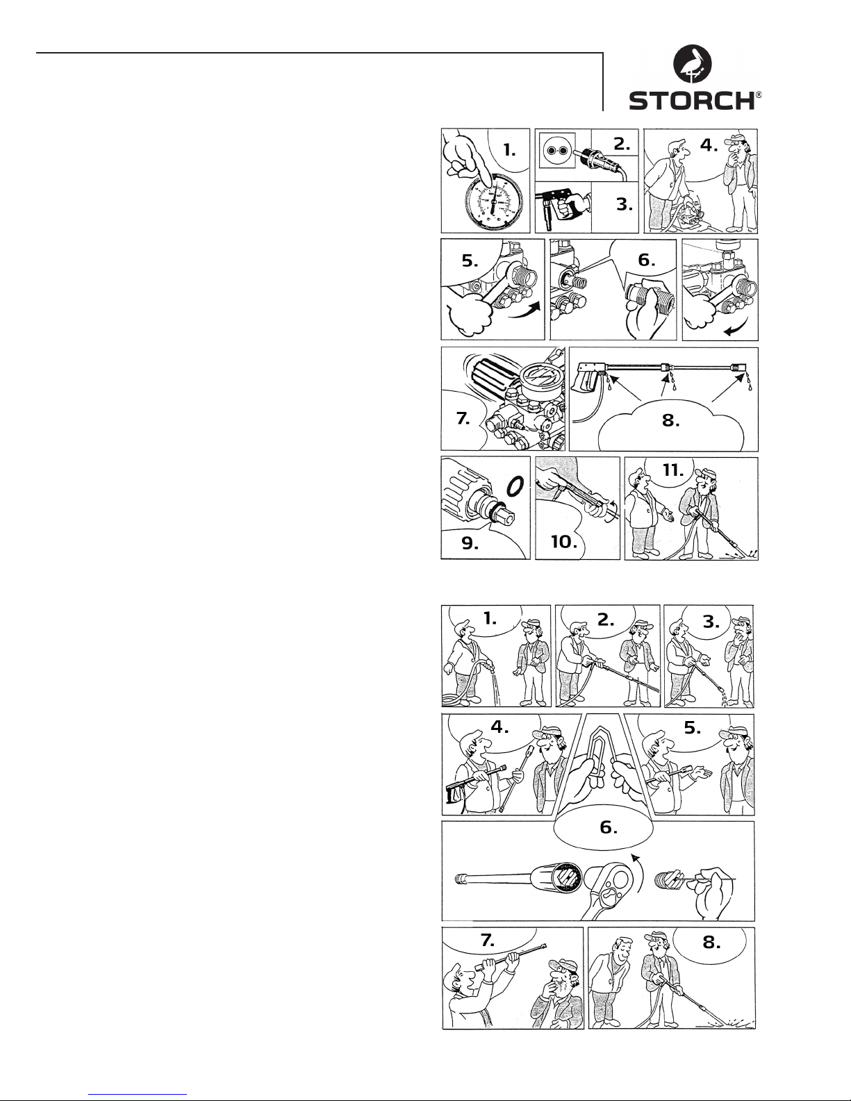
Leckage von Schlauch oder Pistole beheben
Nach dem Schließen der Pistole zeigt das Manometer
vollen Druck an! Der Druckregler schaltet ständig ein und
aus!
1. Wenn das Manometer vollen Druck anzeigt
2. Netzstecker ziehen
3. Pistole drücken zum Druckabbau
4. Nehmen Sie zunächst den Schlauch ab
5. Drehen Sie dann mit einem Gabelschlüssel den
Pumpenausgang los
6. Reinigen Sie den Rückschlagkörper oder wechseln
Sie den O-Ring
7. Durch Druckverlust schaltet der Druckregler ständig
ein und aus
8. An diesen drei Stellen kann Wasser austreten.
Prüfen Sie die Dichtungen und wechseln Sie,
wenn nötig die O-Ringe aus oder lassen Sie
die Pistole vom Händler prüfen
9. Jeweils den O-Ring an der Lanze oder am
HD-Schlauch austauschen
10. Schlauch, Pistole und Lanze wieder miteinander
verschrauben
11. So schnell ist die Störung behoben
Düse verstopft
Es kommt kein Wasser, aber Manometer zeigt vollen
Druck!
1. Spülen Sie zuerst den Schlauch von Rückständen frei
2. Gewöhnlich kommt jetzt ein kräftiger Wasserstrahl
3. Wenn die Lanze nur tropft
4. nehmen Sie sie ab und reinigen Sie die Düse
5. Bei der Flachstrahl-Lanze braucht nur die vordere
Düse gereinigt zu werden
6. Spitzen Gegenstand in das Loch stecken und
die Kappe nach hinten ziehen
Biegen Sie nun eine Büroklammer zurecht und
reinigen Sie die Düse
7. Prüfen Sie mit einem Blick ob die Düse gereinigt ist
8. Nun geht es wieder so gut wie vorher
Page 8

8
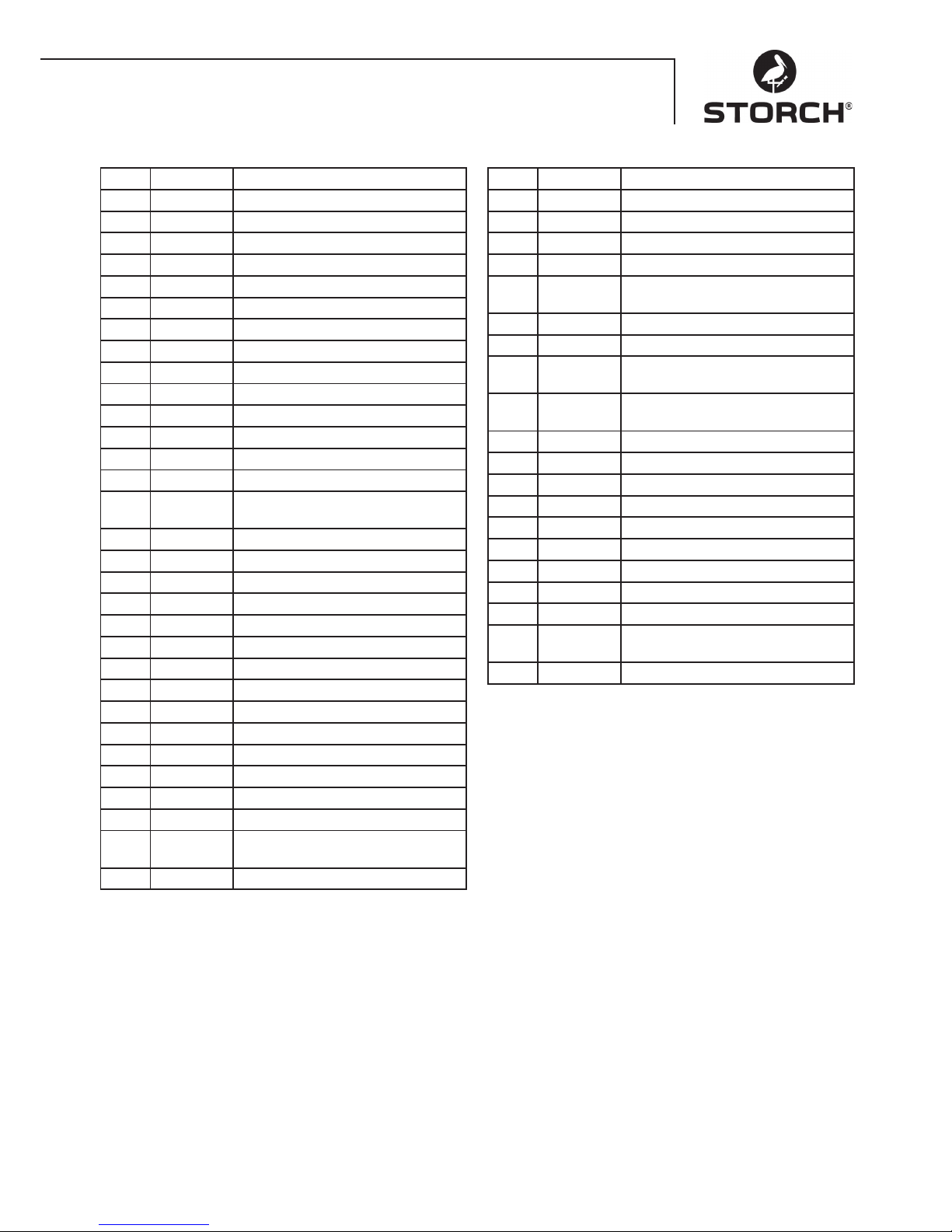
Ventil verschmutzt oder verklebt
- Manometer zeigt keinen vollen Druck
- der Hochdruckschlauch vibriert
- Wasser tritt stoßweise aus
- Ventile können verkleben, wenn das Gerät lange nicht
gebraucht wurde
1. Ist ein Ventil verstopft
2. zeigt das Manometer wenig oder gar keine Druck an
3. oder der Hochdruckschlauch vibriert
4. Drehen Sie mit einem Ringschlüssel das Ventil auf
5. und nehmen Sie die Ventilschraube, das Ventil
und den Gummiring heraus
6. biegen Sie eine Büroklammer zurecht ...
7. und beseitigen Sie den Schmutz aus dem Ventil
- das Ventil innen muss geschlossen sein
8. An diesen drei Stellen kann Wasser austreten.
die Gummidichtung hinten wieder fest draufdrücken
9. die Ventilschraube wieder festziehen
10. ... und bei allen sechs Ventilen wiederholen
11. So schnell ist die Störung behoben
Ventilgehäuse
Page 9
9
Ventilgehäuse
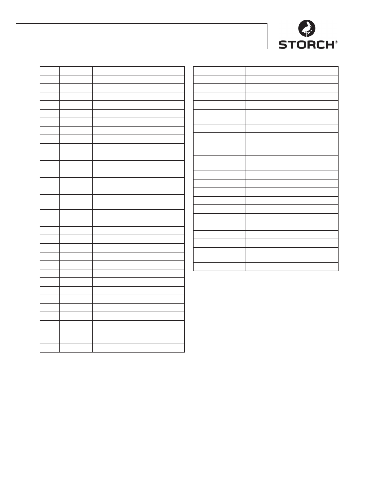
Pos. Art.-Nr. Bezeichnung
1 65 62 69 Ventilgehäuse
2 65 62 71 Ventilstopfen
3 65 62 72 Ventilsstopfen mit R1/4"IG
4 65 63 26 Ventil
5 65 62 74 Dichtstopfen M8 x 1
6 65 62 76 Dichtstopfen M10 x 1
7 65 62 66 O-Ring 12 x 2
8 65 62 77 O-Ring 11 x 1,5
9 65 62 78 Edelstahlsitz
10 65 62 79 Sicherungsring
11 65 62 81 Anlaufentlastungsventil
11.1 65 62 82 Edelstahlkugel 10,0 mm
12 65 62 83 Edelstahlfeder
13 65 62 84 Verschlussschraube
14 65 62 86 Steuerkolben 6 mm für
AZ mit Dichtungen
15 65 62 87 Parbaks für Kolben 14 mm
16 65 62 88 Parbaks für Spindel 6 mm
17 65 62 89 MS-Scheibe
18 65 62 91 Kolbenführung 6 mm
19 65 62 92 Mutter M6
20 65 62 93 Feder schwarz für AZ-Pumpe
21 65 62 94 Federdruckscheibe
22 65 62 96 Kugellager
23 65 62 97 Handrad M6 für AZ-Pumpe
24 65 62 98 Mutter M6 mit SW8
25 65 62 99 Kappe für Handrad AZ-Pumpe
26 65 63 01 Manometer
27 65 63 02 Stützring
28 65 63 03 Manschette 14 x 24 x 5/2,5
28.1 65 63 04 Gewebe-Manschette
14 x 24 x 5/2,5
29 65 63 06 Backring 14 x 24
Pos. Art.-Nr. Bezeichnung
30 65 63 07 O-Ring 24 x 2
31 65 63 08 Leckagering
32 65 63 09 Zwischenring mit Abstützung
33 65 63 11 Rückschlagfeder
34 65 63 12 Ausgangsteil für
Kugelrückschlagventil
35 65 63 13 Verschlussstopfen
36 65 62 37 Aluminium-Dichtring
42 65 62 63 Innensechskantschraube
M8 x 25 - A2
43 65 63 14 Innensechskantschraube
M8 x 45 - A2
44 65 63 16 Dichtring Kupfer
45 65 63 17 Sauganschluss
46 65 61 16 Wasserfilter
48 65 61 17 Gummi Dichtring
49 65 61 18 Steckkupplung
50 65 63 18 O-Ring
52 65 63 19 O-Ring 18 x 2
53 65 63 27 Reparatur-Satz Ventile
54 65 63 22 Reparatur-Satz Manschetten
55 65 63 23 Steuerkolben komplett
mit Handrad
56 65 63 28 Ventilgehäuse komplett
Page 10
10
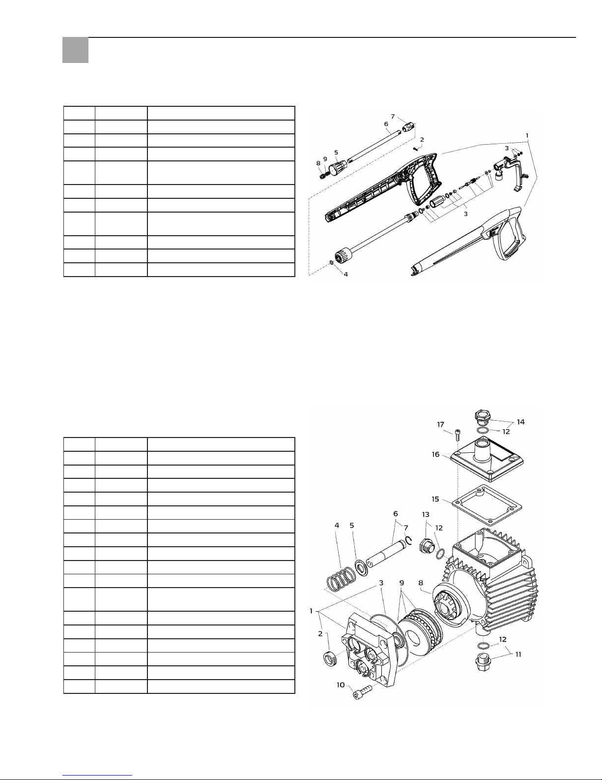
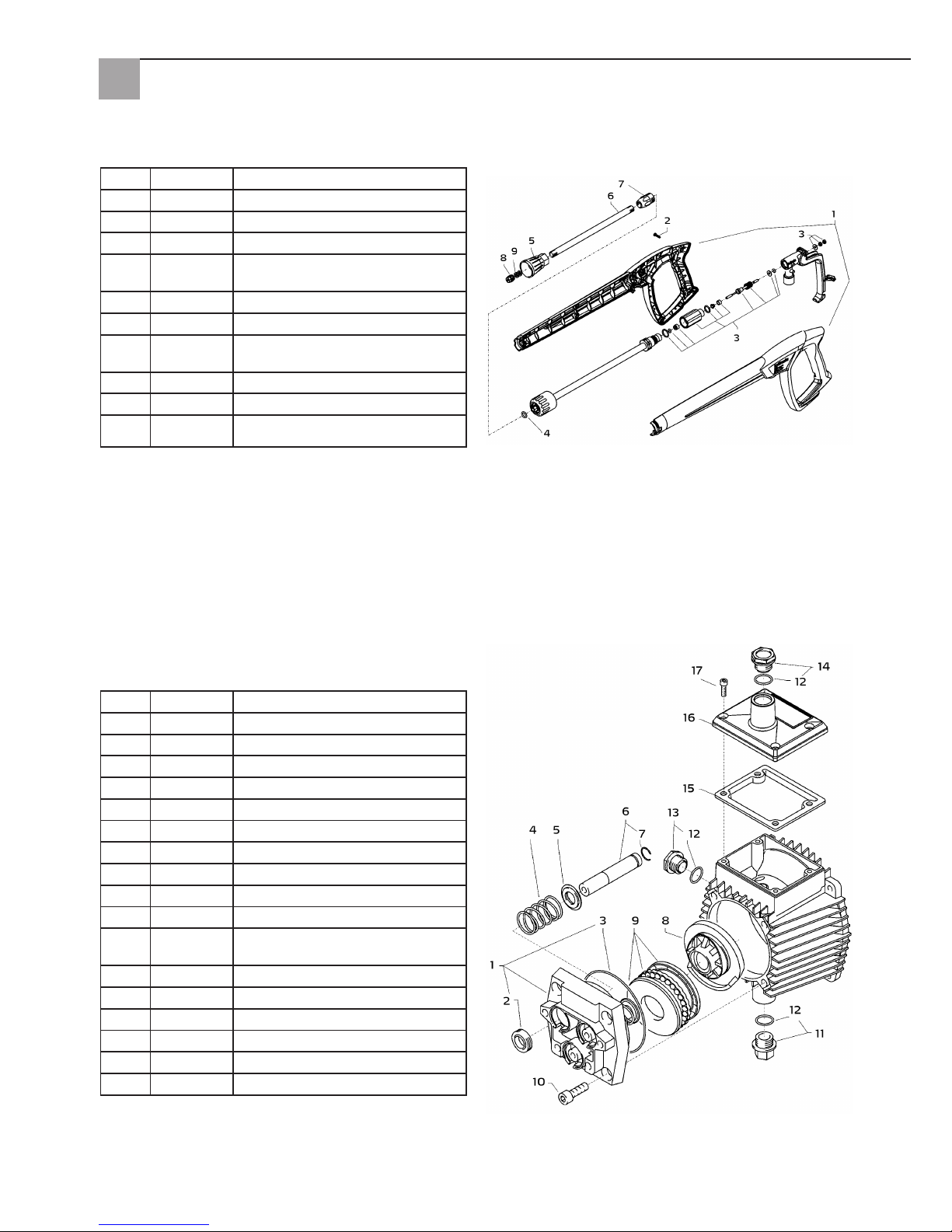
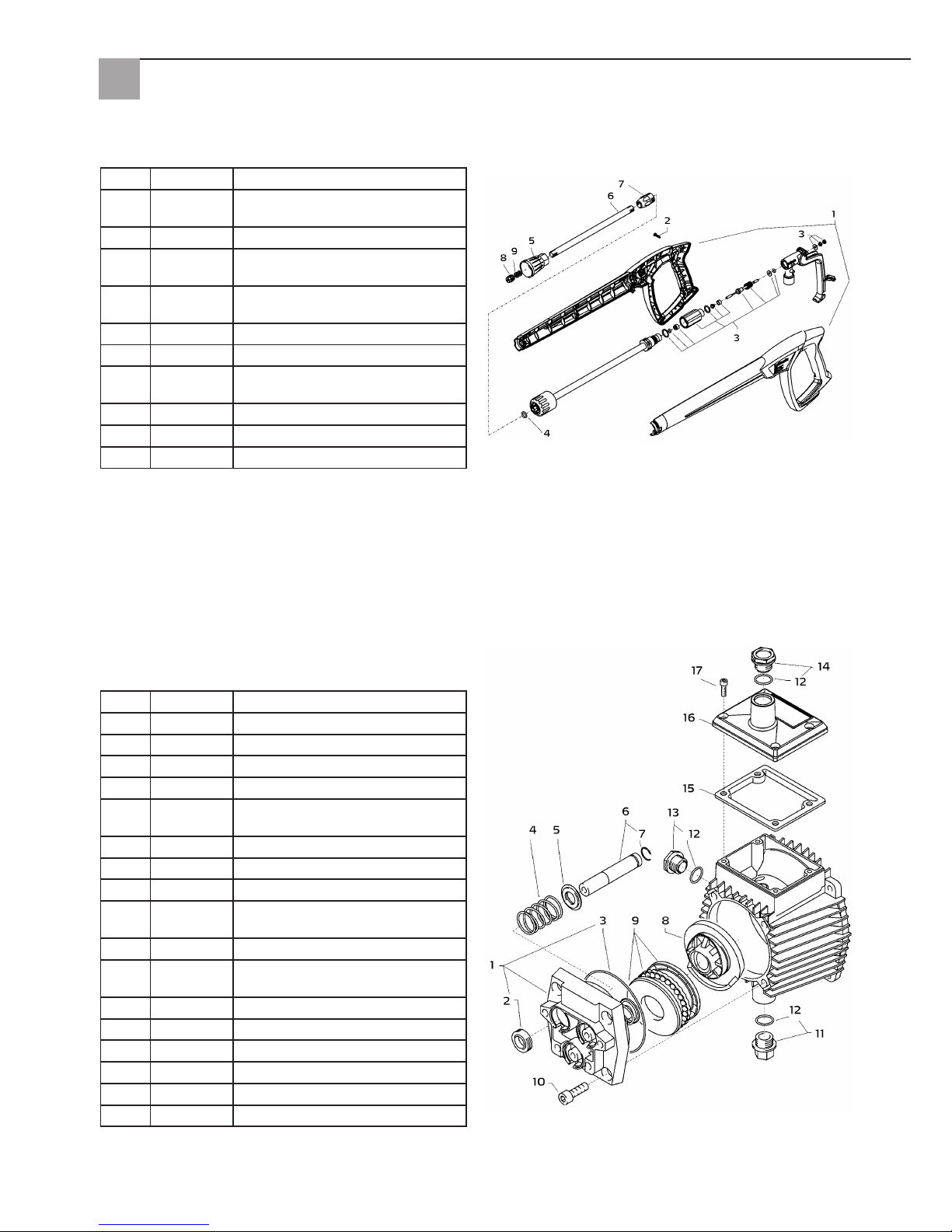
Pistole mit Lanze
Getriebeteil
Pos. Art.-Nr. Bezeichnung
1 65 62 52 Gehäusplatte
2 65 62 53 Öldichtung 14 x 24 x 7
3 65 62 54 O-Ring 83 x 2
4 65 62 56 Plungerfeder
5 65 62 57 Federdruckscheibe 14 mm
6 65 62 58 Plunger 14 mm AZ-L
7 65 62 59 Sprengring 14 mm
8 65 63 31 Taumelscheibe 9,5°
9 65 62 62 Axial-Rillenkugellager 3-teilig
10 65 62 63 Innensechskantschraube M8 x 25
11 65 62 64 Ölablassstopfen M18 x 1,5
mit Magnet
12 65 62 66 O-Ring 12 x 2
13 65 64 33 Ölschauglas
14 65 64 32 Ölverschlussschraube rot
15 65 62 67 Dichtung Öldeckel
16 65 62 68 Deckel Ölgehäuse
17 65 60 98 Innensechskantschraube M5 x 12
Pos. Art.-Nr. Bezeichnung
1 65 62 28 Pistolenschale rechts + links
2 65 62 29 Schraube 3,5 x 14
3 65 62 31 Reparatursatz Pistolenhandgriff
4 65 65 59 O-Ring ST30 für HD-Schlauch
und Lanze
5 65 62 32 Düsenschutz M12 x 1
6 65 62 33 Rohr 500 mm
7 65 62 34 ST30 Nippel M22 x 1,5/R1/4"
mit ISK
8 65 63 29 Flachstrahldüse
9 65 62 37 Aluminium Dichtring
o. Abb.
65 65 33 HD-Pistolenhandgriff
Page 11
11
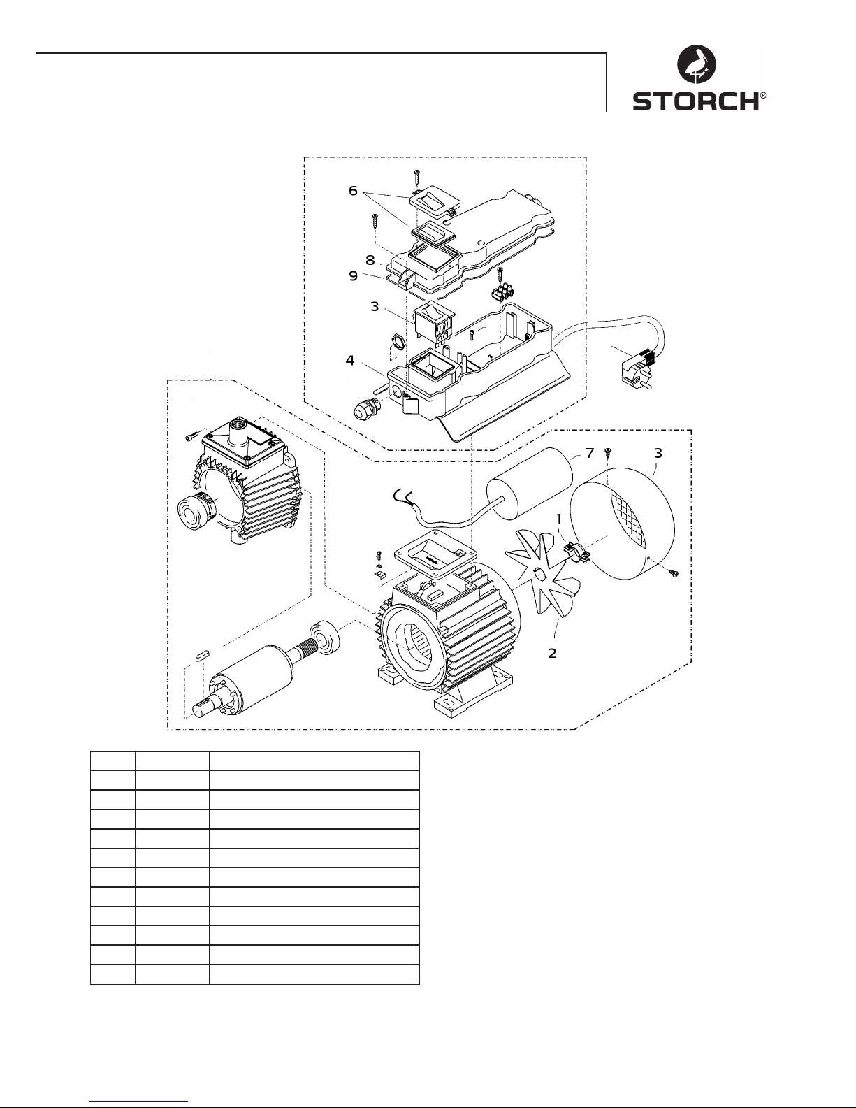
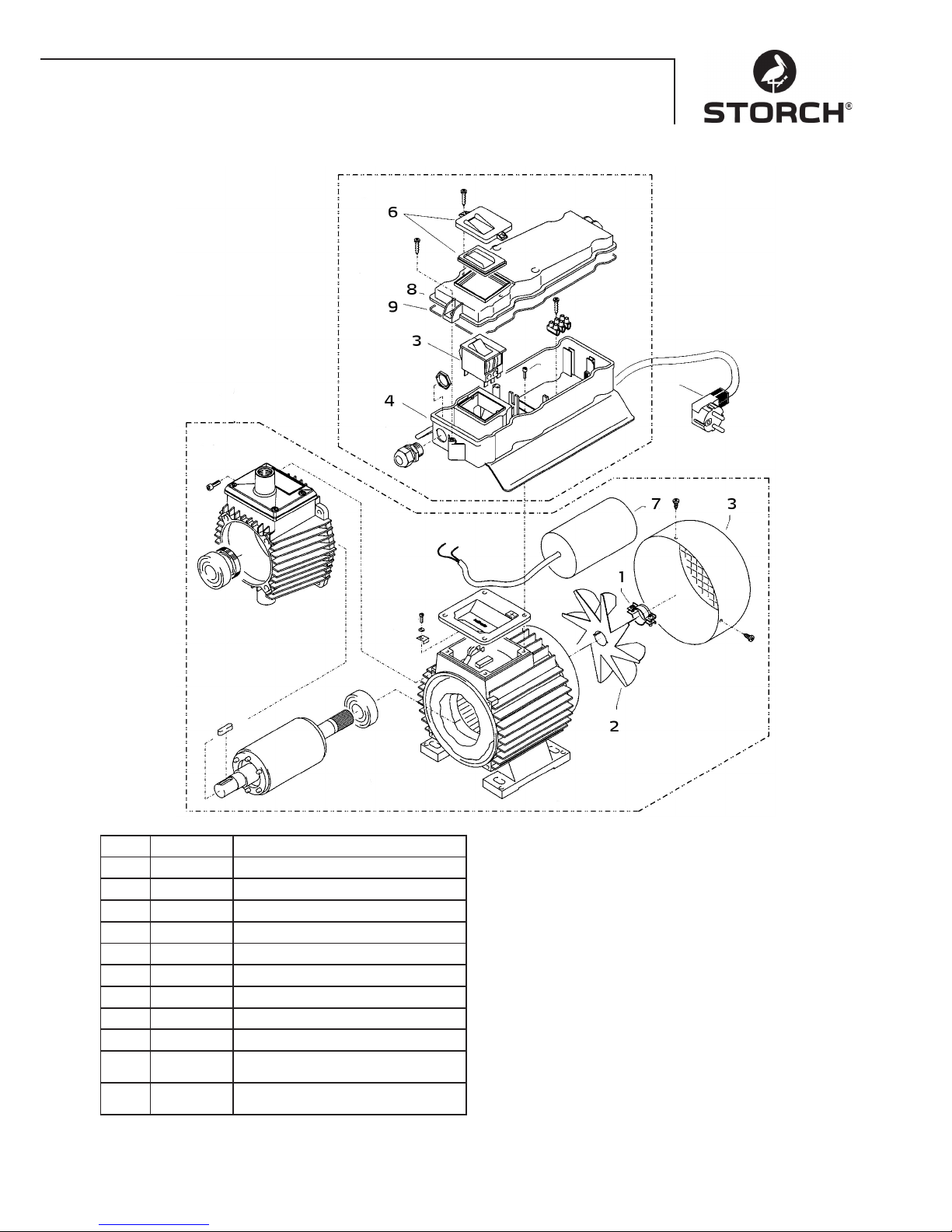
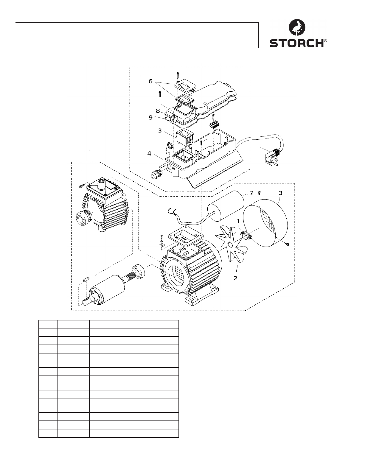
Motor
Pos. Art.-Nr. Bezeichnung
1 65 62 38 Schelle für Lüfterrad
2 65 62 39 Lüfterrad
3 65 62 41 Lüfterhaube
4 65 62 42 Schaltkasten-Unterteil
5 65 63 32 Ein-Ausschalter 12 A
6 65 62 44 Schalterabdeckung inkl. Dichtung
7 65 65 64 Kondensator 40 mycroF
8 65 62 47 Deckel für Schaltkasten
9 65 62 48 Dichtung für Deckel
o. Abb.
65 63 33 Motor komplett
o. Abb.
65 63 34 Schaltkasten komplett
Page 12

12
Prüfungen
Die Maschine ist nach den „Richtlinien für Flüssigkeitsstrahler“ bei Bedarf, jedoch mindestens alle 12 Monate durch
eine Sachkundingen darauf überprüft werden, ob ein sicherer Betrieb weiterhin gewährleistet ist. Die Ergebnisse der
Prüfung sind schriftlich festzuhalten. Formlose Aufzeichnungen genügen.
Unfallverhütung
Die Maschine ist so ausgerüstet, daß bei sachgemäßer Bedienung Unfälle ausgeschlossen sind. Die Bedienungsperson
ist auf die Verletzungsgefahr durch heiße Maschinenteile und den Hochdruckstrahl hinzuweisen. Die „Richtlinien für
Flüssigkeitsstrahler“ sind einzuhalten.
Ölwechsel
Vor jeder Inbetriebnahme Ölstand am Ölschauglas überprüfen. (Waagerechte Position beachten!) Ölstand sollte bei der
Mitte des Ölschauglases sein. Bei hoher Luftfeuchtigkeit und Temperaturschankungen ist Kondenswasserbildung möglich, dann muß das Öl gewechselt werden (graue Farbe).
Erster Ölwechsel nach ca. 50 Betriebsstunden. Danach ist kein Ölwechsel für die Lebensdauer des Gerätes erforderlich.
Sollte es nötig sein, bei einer Reparatur, oder weil das Öl eine graue Farbe hat, das Öl zu wechseln, so ist über einem
Behälter die Ölablaßschraube zu öffnen und das Gerät zu entleeren. Das Öl muss in einem Behälter aufgefangen und
anschließend vorschriftsmäßig entsorgt werden. Neues Öl: 0,25 l - Motoröl W 15/40.
Ölleckage
Bei Ölaustritt sofort den nächsten Kundendienst (Händler) aufsuchen. (Umweltschäden, Getriebeschaden)
Garantie
Garantiebedingungen:
Für unsere Geräte gelten die gesetzlichen Gewährleistungsfristen von 12 Monaten ab Kaufdatum / Rechnungsdatum
des gewerblichen Endkunden. Sind längere Fristen im Wege einer Garantieerklärung von uns ausgelobt, sind diese
extra in den Bedienungsanleitungen der betroffenen Geräte ausgewiesen.
Geltendmachung:
Bei Vorliegen eines Gewährleistungs- bzw. Garantiefalles bitten wir, dass das komplette Gerät zusammen mit der
Rechnung frei an unser Logistik Center in Berka oder an eine von uns autorisierte Service- Station eingeschickt wird.
Zuvor bitten wir Sie, uns unter unserer kostenlosen STORCH Service-Hotline 08 00 . 7 86 72 47 zu kontaktieren.
Gewährleistungs- bzw. Garantieanspruch:
Reparaturansprüche bestehen ausschließlich an Werkstoff- oder Fertigungsfehler sowie ausschließlich bei bestimmungsgemäßer Verwendung des Geräts. Verschleißteile fallen nicht unter derartige Ansprüche. Sämtliche Ansprüche
erlöschen durch den Einbau von Teilen fremder Herkunft, bei unsachgemäßer Handhabung und Lagerung sowie bei
offensichtlicher Nichtbeachtung der Betriebsanleitung.
Durchführung von Reparaturen:
Sämtliche Reparaturen dürfen ausschließlich durch unser Werk oder von STORCH autorisierten Service-Stationen
durchgeführt werden.
Page 13

13
EG-Konformitätserklärung
Name / Anschrift des Ausstellers: STORCH Malerwerkzeuge & Profigeräte GmbH
Platz der Republik 6-8
D - 42107 Wuppertal
Hiermit erklären wir,
dass das nachstehend genannte Gerät aufgrund dessen Konzipierung und Bauart sowie in der von uns in
Verkehr gebrachten Ausführung den einschlägigen, grundlegenden Sicherheits- und Gesundheitsanforderungen der EG-Richtlinien entspricht.
Bei einer nicht mit uns abgestimmten Änderung des Gerätes verliert diese Erklärung ihre Gültigkeit.
Bezeichnung des Gerätes: Hochdruckreiniger 120 bar Compact
Geräte-Typ: Hochdruckreiniger
Artikel-Nummer: 65 60 05
Angewandte Richtlinien
Maschinen-Richtlinie: 2006 / 42 / EG
Niederspannungs-Richtlinie: 2006 / 95 / EG
EG-Richtlinie Elektromagnetische
Verträglichkeit: 2004 / 108 / EG
EG-Lärm-Richtlinie: 2005 / 88 EG, Art. 13
Hochdruckwasserstrahlmaschinen Anhang 3, Teil B, Abschnitt 27
Bevollmächtigter für die Zusammenstellung der technischen Unterlagen:
STORCH Malerwerkzeuge & Profigeräte GmbH
Platz der Republik 6-8
42107 Wuppertal
Jörg Heinemann
- Geschäftsführer -
Wuppertal, 06 - 2013
Page 14

14
NL
Hartelijk dank
voor uw vertrouwen in STORCH. Met deze aankoop hebt u voor een kwaliteitsproduct gekozen.
Als u desondanks suggesties voor verbetering of een probleem hebt, dan horen wij graag van u.
Neem contact op met de buitendienst-medewerker of in dringende gevallen rechtstreeks met ons.
Met vriendelijke groeten,
STORCH serviceafdeling
Telefoon: +49 (0)2 02 . 49 20 - 112
Fax: +49 (0)2 02 . 49 20 - 244
Gratis service-hotline: 08 00. 7 86 72 47
Gratis bestel-hotline: 08 00. 7 86 72 44
Gratis bestel-fax: 08 00. 7 86 72 43
(alleen binnen Duitsland)
Inhoudsopgave Pagina
1. Technische gegevens 15
2. Apparaatbeschrijving / functie 15
3. Water- en reinigings/onderhoudsmiddel-systeem 15
4. Spuitpistool met waslans 16
5. Drukregelaar-veiligheidsklep 16
6. Opstelling: plaatsingslocatie 16
7. Korte gebruiksaanwijzing 17
8. Inbedrijfstelling 17
9. Drukinstelling 18
10. Uitbedrijfname 18
11. Veiligheidsrichtlijnen 18
12. Hulp bij verhelpen van storingen 19 - 20
13. Lijsten met vervangende onderdelen 20 - 23
14. Controles 24
15. Garantie / garantievoorwaarden 24
16. EG-conformiteitverklaring 25
Levering
Hogedrukreiniger, 10 m hogedrukslang, waslans, gebruiksaanwijzing.
Page 15
15
Technische gegevens
Werkdruk, traploos regelbaar 10 - 120 bar
Toegestane overdruk 135 bar
Watervermogen 10 l / min bij 2.800 omw / min
Toevoer van warm water tot 60° C
Aanzuighoogte 1 m
Hogedrukslang 10 m
Elektrische aansluitwaarde 230 V / 50 Hz, 11 A
Elektrisch vermogen 2.500 W
Gewicht (zonder toebehoren) 18,5 kg
Sproeigrootte 20042
Geluidsvermogensniveau gemeten: 71 dB (A)
gegarandeerd: 91 dB (A)
Terugslag van de lans ca. 27 N
Vibraties van de lans 1,9 m/s
2
Apparaatbeschrijving / functie
1. Aanvoer wateraansluiting met filter
2. Aanzuigslang met filterkorf (optioneel toebehoren)
3. Hogedrukpomp
4. Manometer
5. Drukregelaar-veiligheidsklep
6. Hogedrukslang
7. Spuitpistool
8. Waslans
Water
Water- en reinigings/
onderhoudsmiddel-systeem
Het water kan onder druk aan de hogedrukpomp worden
geleverd of direct uit een drukloos reservoir worden aangezogen. Vervolgens wordt het water door de hogedrukpomp onder druk naar de waslans geleid. Door de sproeier op de waslans wordt de hogedrukstraal gevormd.
Spuitpistool met waslans
De machine kan alleen met het spuitpistool worden
gebruikt bij indrukken van de veiligheidshandel.
Druk op de handel om het spuitpistool te openen. Het
water wordt nu naar de sproeier getransporteerd. De
spuitdruk wordt opgebouwd en bereikt snel de gekozen
werkdruk.
Door de handel los te laten, wordt het pistool gesloten
en wordt verder vrijkomen van water uit de waslans voorkomen. Door de drukstoot bij het sluiten van het pistool
wordt de drukregelaar-veiligheidsklep geopend; de pomp
transporteert met de gekozen werkdruk naar de waslans.
Het spuitpistool is een veiligheidsinstallatie,
reparaties mogen alleen door deskundigen
worden uitgevoerd. Bij vervanging mogen
alleen door de fabrikant toegestane onderdelen worden gebruikt.
Drukregelaar-veiligheidsklep
De drukregelaar-veiligheidsklep beschermt de machine
tegen te hoge overdruk en is zodanig gebouwd dat deze
niet boven de toegestane bedrijfsdruk kan worden ingesteld. De begrenzingsmoer van de draaigreep is met lak
verzegeld.
Druk op de draaigreep om de werkdruk en spuithoeveelheid traploos in te stellen.
Vervanging, reparaties, nieuwe instellingen en
verzegelingen mogen alleen door deskundigen
worden uitgevoerd.
Page 16

16
Wateraansluiting
Controleer of de hogedrukreiniger kan beschikken over de
pagina 3 (Technische gegevens) vermelde waterhoeveelheid (liter per minuut).
Controle: watertoevoerslang 1 minuut in een emmer laten
lopen. De waterhoeveelheid moet minstens voldoen aan
de informatie op pagina 15!
Waterterkort leidt tot snelle slijtage van de
dichting (geen garantie).
Motorveiligheidsschakelaar
De motor wordt door een motorveiligheidsschakelaar beschermd tegen overbelasting. Bij overbelasting schakelt de
motorveiligheidsschakelaar de motor uit. Bij herhaald uitschakelen van de motor door de motorveiligheidsschakelaar
dient de oorzaak van de storing te worden verholpen (zie pagina 7/8).
Vervangings- en testwerkzaamheden mogen alleen door deskundigen worden uitgevoerd wanneer de machine van het lichtnet is losgekoppeld, d.w.z. dat de stekker uit het stopcontact moet zijn getrokken.
Opstelling
Plaats
De machine mag niet in brand- en explosiegevaarlijke ruimtes of in plassen worden geplaatst en gebruikt.
Het apparaat mag niet water worden gebruikt.
OPGELET:
Nooit oplosmiddelhoudende vloeistoffen zoals lakverdunningen, benzine, olie of vergelijkbare vloeistoffen
aanzuigen. Neem de informatie van de middelen in acht! De dichtingen in het apparaat zijn niet bestand
tegen oplosmiddelen! De sproeinevel van oplosmiddelen is zeer ontvlambaar, explosiegevaarlijk en giftig.
OPGELET:
Bij gebruik met warm water van 60° C treden hoge temperaturen op.
Raak het apparaat niet aan zonder beschermhandschoenen.
Elektrische aansluiting
De machine wordt geleverd met een aansluitkabel van 5 m met stekker. De stekker moet worden aangesloten op een correct geïnstalleerd stopcontact met randaarde en aardlekschakelaar van 30 mA. Het stopcontact dient aan de netzijde met 16 A worden gezekerd.
Bij gebruik van een verlengkabel moet deze over randaarde beschikken die correct op de stekkerverbindingen in aangesloten. De aders van de verlengkabel moeten een minimale diameter van 2,5 mm² hebben. De stekkerverbindingen
dienen spatwaterdicht te zijn en mogen niet op een natte bodem liggen.
Elektrische gegevens
Het apparaat heeft een spanningsbereik dat elektrische gevaren voor mens en dier kan opleveren. Het mag alleen door
geautoriseerde personen worden geopend en / of worden gedemonteerd.
Instandhouding en reparaties mogen alleen door STORCH of door STORCH geautoriseerde servicestations worden uitgevoerd. Het gebruik van het apparaat is de verantwoordelijkheid van en voor risico van de gebruiker.
Page 17
17
Korte gebruiksaanwijzing
Apparaat alleen horizontaal gebruiken!
1. Hogedrukslang aan spuitpistool en apparaat schroeven.
2. Wateraansluiting aan aanzuigkant tot stand brengen.
3. Apparaat ontluchten (spuitpistool diverse keren openen en sluiten).
4. Stroomaansluiting maken.
5. Apparaat bij geopend spuitpistool inschakelen en de wasprocedure beginnen.
6. Na beëindiging van de wasprocedure de pomp volledig leegmaken (zonder zuig- en drukslang ca. 20 sec. de motor
inschakelen).
• Alleen schoon water gebruiken!
• Tegen vorst beschermen!
OPGELET:
Neem de voorschriften van het waterbedrijf in acht. De machine mag conform EN 61770 niet direct op de openbare
waterleiding worden aangesloten.
Korte aansluiting is conform DVGW (Deutscher Verband des Gas- und Wasserfaches) toegestaan wanneer er een
terugstroomblokkering met buisbeluchting in de toevoerleiding is ingebouwd.
Ook directe aansluiting op de openbare drinkwatervoorziening is toegestaan met een vrije uitloop conform EN 61770;
bijv. door gebruik van een reservoir met een vlotterklep.
Directe aansluiting op een niet voor de drinkwatervoorziening bestemd leidingnetwerk is toegestaan.
Hogedrukslang-leiding en spuitinstallatie
De tot de uitrusting van de machine behorende hogedrukslang-leiding en spuitinstallatie bestaan uit hoogwaardig
materiaal en zijn op de bedrijfsomstandigheden van de machine afgestemd en volgens de voorschriften aangeduid.
Maximale watertoevoerleiding 20 m.
Bij vervanging mogen alleen door de fabrikant toegestane en volgens de voorschriften aangeduide onderdelen worden gebruikt. Hogedrukslang-leiding en spuitinstallaties dienen drukdicht te worden aangesloten.
Rijd niet over de hogedrukslang-leiding, trek deze te niet hard aan en verdraai de leiding niet. De hogedrukslang-leiding mag niet over scherpe randen worden getrokken, anders vervalt de garantie.
Water
Inbedrijfstelling
1.
Oliepeil controleren
Olie moet in het kijkglas
zichtbaar zijn
2.
Hogedruk-lans met handpistool
verbinden
3.
Hogedrukslang zonder lussen afrollen en met
handpistool en pomp verbinden. Bij verlenging
max. 20 m HD-slang gebruiken of
2 x 10 m met slangverbindingen.
Verbinding
hogedrukslang naar lans.
4.
De machine kan naar
keuze aan de drukwaterleiding met koud
of tot maximaal 60° C
heet water worden aangesloten. Let er bij extern
aanzuigen op dat het water schoon is.
Tip:
Water-ingangsfilter art.-nr.
65 65 60 gebruiken.
De slangdoorsnede moet ten
minste 1/2“ = 12,7 mm bedragen
(vrije doorgang). Zeef nr. 1 moet
altijd schoon zijn.
5.
Maximale aanzuighoogte 1,0 m
Zie Technische gegevens, pagina 15.
Page 18
18
Drukinstelling
Door draaien aan het handwiel. De maximale druk is vooraf ingesteld.
Uitbedrijfname
1. Apparaat uitschakelen
2. Watertoevoer blokkeren
3. Open het pistool eventjes totdat de druk is opgebou-
wd
4. Pistool vergrendelen
5. Waterslang en hogedrukslang aanschroeven
6. Pomp leegmaken: motor ca. 20 seconden inscha-
kelen
7. Trek de stekker uit het stopcontact
8. Winter: pomp in vorstvrije ruimte bewaren
9. Waterfilter reinigen
Dat is verboden!
Kinderen mogen niet met
hogedrukreinigers werken!
Richt de waterstraal nooit op
mensen of dieren!
Sproei het apparaat niet af
met hogedruk of waterstraal!
De kabel niet beschadigen of
ondeskundig repareren!
Richt de waterstraal niet op
stopcontacten!
HD-slang niet met lussen
of knikken trekken! Trek de
slang niet over scherpe randen!
Page 19
19
Lekkage van slang of pistool verhelpen
Na het sluiten van het pistool geeft de manometer de
volledige druk aan! De drukregelaar schakelt constant in
en uit!
1. Wanneer de manometer volledige druk aangeeft
2. Trek de stekker uit het stopcontact
3. Haal het pistool over om de druk op te bouwen
4. Verwijder vervolgens de slang
5. Draai hierna met een steeksleutel de pompuitgang
los
6. Reinig het terugslagonderdeel of vervang de O-ring
7. Door drukverlies schakelt de drukregelaar constant in
en uit
8. Op deze drie plaatsen kan er water vrijkomen. Con-
troleer de dichtingen en vervang indien nodig de
O-ringen of laat het pistool door de handelaar controleren
9. Vervang altijd de O-ring op de lans of de HD-slang
10. Slang, pistool en lans weer aan elkaar schroeven
11. Zo is de storing heel snel verholpen
Sproeierkop verstopt
Er komt geen water uit de sproeier, maar de manometer
geeft de volledige druk aan.
1. Spoel eerst de resten uit de slang
2. Meestal komt er nu een krachtige waterstraal
3. Als de lans alleen druppelt,
4. verwijdert u deze en reinigt u de sproeier
5. Bij de lans voor platte straal hoeft alleen de voorste
sproeier te worden gereinigd
6. Steek een puntig voorwerp in het gat en trek de kap
naar achter. Buig een paperclip recht en reinig de
spoeier
7. Kijk of de sproeier schoon is
8. Nu werkt alles weer prima
Page 20
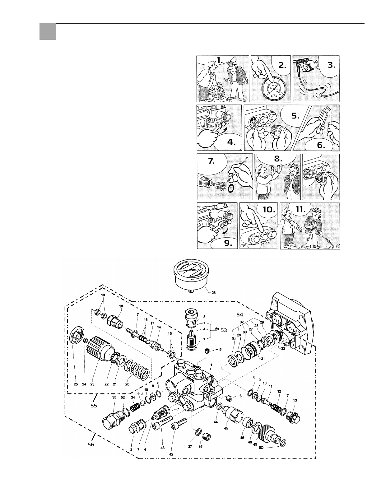
20
Klep vuil of vast geplakt
• Manometer toont geen volledige druk
• De hogedrukslang trilt
• Water komt met horten en stoten naar buiten
• Kleppen kunnen vast plakken wanneer het apparaat
lang niet is gebruikt
1. Als een klep is verstopt,
2. toont de manometer weinig of helemaal geen druk
3. of de hogedrukslang trilt
4. Draai met een ringsleutel de klep open
5. en verwijder de klepschroef, de klep en de gummring;
6. buig een paperclip recht...
7. en verwijder het vuil uit de klep;
• het binnenste van de klep moet gesloten zijn
8. Op deze drie plaatsen kan er water vrijkomen. Druk
de gummidichting weer stevig aan
9. Draai de klepschroef weer vast
10. ... en herhaal dit bij alle zes kleppen
11. Zo is de storing heel snel verholpen
Klepbehuizing
Page 21
21
Pos. Art. nr. Omschrijving
1 65 62 69 Klepbehuizing
2 65 62 71 Klepstop
3 65 62 72 Klepstoppen met R1/4"IG
4 65 63 26 Ventiel
5 65 62 74 Dichtingsstop M 8 x 1
6 65 62 76 Dichtingsstop M 10 x 1
7 65 62 66 O-ring 12 x 2
8 65 62 77 O-ring 11 x 1,5
9 65 62 78 Edelstalen zitting
10 65 62 79 Zekeringsring
11 65 62 81 Aanloop-ontlastingklep
11.1 65 62 82 Edelstalen kogel 10,0 mm
12 65 62 83 Edelstalen veer
13 65 62 84 Sluitschroef
14 65 62 86 Stuurzuiger 6 mm voor AZ met
dichtingen
15 65 62 87 Parbaks voor zuiger 14 mm
16 65 62 88 Parbaks voor spindel 6 mm
17 65 62 89 MS-schijf
18 65 62 91 Zuigergeleiding 6 mm
19 65 62 92 Moer M6
20 65 62 93 Zwarte veer voor AZ-pomp
21 65 62 94 Veerdrukschijf
22 65 62 96 Kogellager
23 65 62 97 Handwiel M6 voor AZ-pomp
24 65 62 98 Moer M6 met SW8
25 65 62 99 Kap voor handwiel AZ-pomp
26 65 63 01 Manometer
27 65 63 02 Steunring
28 65 63 03 Manchet 14 x 24 x 5/2,5
28.1 65 63 04 Manchet weefsel
14 x 24 x 5/2,5
29 65 63 06 Bakring 14 x 24
Pos. Art. nr. Omschrijving
30 65 63 07 O-ring 24 x 2
31 65 63 08 Lekkagering
32 65 63 09 Tussenring met steun
33 65 63 11 Terugslagveer
34 65 63 12 Uitgangsonderdeel voor
terugslagklep
35 65 63 13 Sluitstoppen
36 65 62 37 Aluminium dichtingsring
42 65 62 63 Zeskante inbusbout
M8 x 25 - A2
43 65 63 14 Zeskante inbusbout
M8 x 45 - A2
44 65 63 16 Koperen dichtingsring
45 65 63 17 Zuigaansluiting
46 65 61 16 Waterfilter
48 65 61 17 Gummi dichtingsring
49 65 61 18 Stekkerkoppeling
50 65 63 18 O-ring
52 65 63 19 O-ring 18 x 2
53 65 63 27 Reparatieset kleppen
54 65 63 22 Reparatieset manchetten
55 65 63 23 Stuurzuiger compleet met hand-
wiel
56 65 63 28 Klepbehuizing compleet
Klepbehuizing
Page 22
22
Pistool met lans
Transmissie
Pos. Art. nr. Omschrijving
1 65 62 52 Behuizingsplaat
2 65 62 53 Oliedichting 14 x 24 x 7
3 65 62 54 O-ring 83 x 2
4 65 62 56 Plunger-veer
5 65 62 57 Veerdrukschijf 14 mm
6 65 62 58 Plunger 14 mm AZ-L
7 65 62 59 Borgring 14 mm
8 65 63 31 Tuimelschijf 9,5°
9 65 62 62 Axiaal groefkogellager 3-delig
10 65 62 63 Zeskante inbusbout M8 x 25
11 65 62 64 Olie-aflaatstop M18 x 1,5 met
magneet
12 65 62 66 O-ring 12 x 2
13 65 64 33 Oliekijkglas
14 65 64 32 Olie-sluitschroef rood
15 65 62 67 Dichting oliedeksel
16 65 62 68 Deksel oliebehuizing
17 65 60 98 Zeskante inbusbout M5 x 12
Pos. Art. nr. Omschrijving
1 65 62 28 Pistoolschaal rechts + links
2 65 62 29 Schroef 3,5 x 14
3 65 62 31 Reparatieset pistoolhandgreep
4 65 65 59 O-ring ST30 voor HD-slang en
lans
5 65 62 32 Sproeierbescherming M12 x 1
6 65 62 33 Buis 500 mm
7 65 62 34 ST30 nippel M22 x 1,5/R1/4" met
ISK
8 65 63 29 Sproeier met platte straal
9 65 62 37 Aluminium dichtingsring
zonder
afb.
65 65 33 HD-pistoolhandgreep
Page 23
23
Motor
Pos. Art. nr. Omschrijving
1 65 62 38 Bevestigingsring voor ventilator
2 65 62 39 Ventilatorwiel
3 65 62 41 Ventilatorkap
4 65 62 42 Schakelkast onderste deel
5 65 63 32 Aan/Uit-schakelaar 12 A
6 65 62 44 Schakelaarafdekking incl. dichting
7 65 65 64 Condensator 40 mycroF
8 65 62 47 Deksel voor schakelkast
9 65 62 48 Dichting voor deksel
zonder
afb.
65 63 33 Motor compleet
zonder
afb.
65 63 34 Schakelkast compleet
Page 24

24
Garantie
Garantievoorwaarden
Voor onze apparaten gelden de wettelijke garantieperioden van 12 maanden vanaf aankoopdatum/factuurdatum van
de eindklant. Indien wij langere perioden in een garantieverklaring hebben toegezegd, dan worden deze speciaal in de
gebruiksaanwijzingen van de desbetreffende apparaten toegelicht.
Indienen van garantieclaims
Bij een garantieclaim vragen wij u het gehele apparaat samen met de rekening franco aan ons logistiekcentrum in Berka of naar een door ons geautoriseerd servicestation te verzenden.
Neem eerst contact op met de STORCH Service-Hotline: 08 00. 7 86 72 47
Garantieclaims
Claims uitsluitend met betrekking tot materiaal- of productiefouten en uitsluitend bij gebruik van het apparaat conform
de voorschriften. Voor slijtdelen gelden deze aanspraken niet. Alle claims vervallen bij inbouw van onderdelen van
externe herkomst, bij verkeerde hantering en opslag en bij het klaarblijkelijk niet in acht nemen van de gebruiksaanwijzing.
Reparaties uitvoeren
Reparaties mogen uitsluitend door onze fabriek of door STORCH geautoriseerde servicestations worden uitgevoerd.
Controles
De machine dient conform de "Richtlijnen voor vloeistofstralers" indien nodig, echter ten minste iedere 12 maanden,
door een deskundige te worden gecontroleerd om te kijken of een veilig gebruik is gegarandeerd. De resultaten van de
test dienen schriftelijk te worden vastgelegd. Informele aantekeningen voldoen.
Ongevalpreventie
De machine is zodanig ontworpen dat bij deskundige bediening ongevallen uitgesloten zijn. De bediener moet worden
gewezen op de risico’s een verwonding op te lopen door hete machinedelen en de hogedrukstraal. De "Richtlijnen voor
vloeistofstralers" dienen in acht te worden genomen.
Olievervanging
Voor ieder gebruik de oliestand via de oliekijkglas controleren. (zorg voor horizontale positie!) Oliestand dient in het
midden van het oliekijkglas te staan. Bij hoge luchtvochtigheid en temperatuurvariaties is condenswatervorming mogelijk; in dit geval moet de olie worden vervangen (grijze kleur).
Eerste olievervanging na ca. 50 bedrijfsuren. Hierna hoeft de olie gedurende de levensduur van het apparaat niet meer
te worden vervangen. Als het nodig is om de olie te vervangen - bij een reparatie of omdat de olie een grijze kleur heeft
- open de olie-aflaatschroef dan boven een reservoir en maakt het apparaat leeg. De olie moet in een reservoir worden
opgevangen en vervolgens volgens de voorschriften worden afgevoerd. Nieuwe olie: 0,25 l - motorolie W 15/40.
Olielekkage
Bij olieverlies direct de klantendienst (handelaar) bezoeken. (schade aan milieu en apparaat)
Page 25
25
EG-conformiteitsverklaring
Naam/adres van de opsteller: STORCH Malerwerkzeuge & Profigeräte GmbH
Platz der Republik 6 - 8
D - 42107 Wuppertal
Hiermee verklaren we dat de volgende machine
Beschrijving van de machine: Hogedrukreiniger 120 bar Compact
Machinetype: Hogedrukreiniger
aan de geldende bepalingen van de volgende richtlijnen voldoet:
Machinerichtlijn: 2006 / 42 / EG
Laagspanningsrichtlijn: 2006 / 95 / EG
EG-richtlijn
Elektromagnetische compatibiliteit: 2004 / 108 / EG
EG-geluidsrichtlijn: 2005 / 88 EG, Art. 13
Hogedruk-waterstraalmachines
Bijlage 3, deel B, paragraaf 27
Verantwoordelijke voor samenstelling van de technische documentatie:
STORCH Malerwerkzeuge & Profigeräte GmbH
Platz der Republik 6 - 8
D-42107 Wuppertal
Jörg Heinemann
- Directeur -
Wuppertal, 06 - 2013
Page 26

26
FR
Merci
pour la confiance que vous témoignez à STORCH. En achetant ce produit, vous avez opté pour un produit de qualité.
Si vous avez des suggestions d'amélioration ou si vous rencontrez des problèmes, nous sommes à votre écoute.
Contactez votre représentant du service après-vente ou contactez-nous directement en cas d'urgence.
Sincères salutations
SAV STORCH
Téléphone : +49 (0)2 02 . 49 20 - 112
Télécopie : +49 (0)2 02 . 49 20 - 244
Ligne d'assistance SAV gratuite : +49 800 7 86 72 47
Service gratuit de commande par téléphone : +49 800. 7 86 72 44
Fax de commande gratuit : +49 800. 7 86 72 43
(uniquement en Allemagne)
Table des matières Page
1. Données techniques 27
2. Description de l'appareil / Fonctionnement 27
3. Système d'eau et de produit d'entretien 27
4. Pistolet pulvérisateur avec lance de lavage 28
5. Vanne de sûreté à manostat 28
6. Installation : site 28
7. Instructions de service succinctes 29
8. Mise en service 29
9. Réglage de la pression 30
10. Mise hors service 30
11. Consignes de sécurité 30
12. Aide lors de l'élimination de défauts 31 - 32
13. Nomenclatures 32 - 35
14. Contrôles 36
15. Garantie / Conditions de garantie 36
16. Déclaration de conformité CE 37
Etendue des fournitures
Nettoyeur haute pression, flexible haute pression 10 m, lance de lavage, mode d'emploi.
Page 27
27
Données techniques
Pression de travail, réglable en continu 10 - 120 bar
Surpression admissible 135 bar
Débit d'eau 10 l / mn pour 2800 tours / mn
Arrivée d'eau chaude jusqu'à 60° C
Hauteur d'aspiration 1 m
Flexible haute pression 10 m
Valeur de connexion électrique 230 V / 50 Hz, 11 A
Puissance électrique 2.6500 W
Poids (sans accessoires) 18,5 kg
Dimension des buses 20042
Niveau de puissance sonore mesuré : 71 dB (A)
garantit : 91 dB (A)
Recul au niveau de la lance env. 27 N
Vibrations intervenant sur la lance 1,9 m/s
2
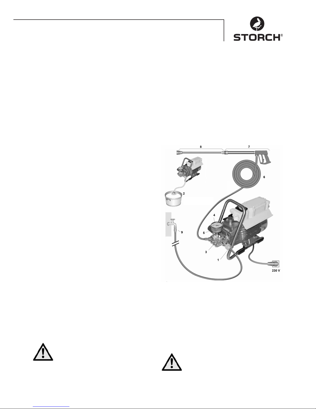
Description de l'appareil / Fonctionnement
1. Raccord d'arrivée d'eau avec filtre
2. Tuyau d'aspiration avec panier filtrant (accessoires
spéciaux)
3. Pompe haute pression
4. Manomètre
5. Vanne de sûreté à manostat
6. Flexible haute pression
7. Pistolet pulvérisateur
8. Lance de lavage
Eau
Système d'eau et de produit d'entretien
L'eau peut être alimentée sous pression dans la pompe
haute pression ou aspirée directement depuis un réservoir
sans pression. L'eau est ensuite alimentée depuis la pompe haute pression vers la lance de lavage sous pression.
Le jet haute pression est formé par la buse sur la lance de
lavage.
Pistolet pulvérisateur avec lance de lavage
Le pistolet pulvérisateur permet le fonctionnement de la
machine uniquement si le levier de commande de sécurité est actionné.
Le pistolet à main est ouvert par actionnement du levier.
L'eau est alors transportée vers la buse. La pression de jet
monte et atteint rapidement la pression de travail sélectionnée.
Si l'on relâche le levier de commande, le pistolet se ferme, empêche ainsi que du liquide ne continue de sortir. La poussée lors de la fermeture du pistolet permet
d'ouvrir la vanne de sûreté à soupape de surpression et la
pompe refoule vers la lance de lavage avec la pression de
travail sélectionnée.
Le pistolet pulvérisateur est un dispositif de
sécurité. Seul un expert est habilité à procéder
à des réparations. Si un remplacement est
nécessaire, il convient d'utiliser exclusivement
des composants homologués par le fabricant.
Vanne de sûreté à manostat
La vanne de sûreté à soupape de surpression protège
la machine contre les surpressions inadmissibles et est
conçue de sorte à ne pas pouvoir être réglée à une pression supérieure à celle admissible pour le fonctionnement.
L'écrou de limitation de la poignée tournante est scellé
avec du vernis.
En actionnant la poignée tournante, il est possible de régler en continu la pression de service et la quantité pulvérisée.
Remplacement, réparations, nouveaux réglages et scellages sont des opérations réservées
à l'expert.
Page 28
28
Raccord d'eau
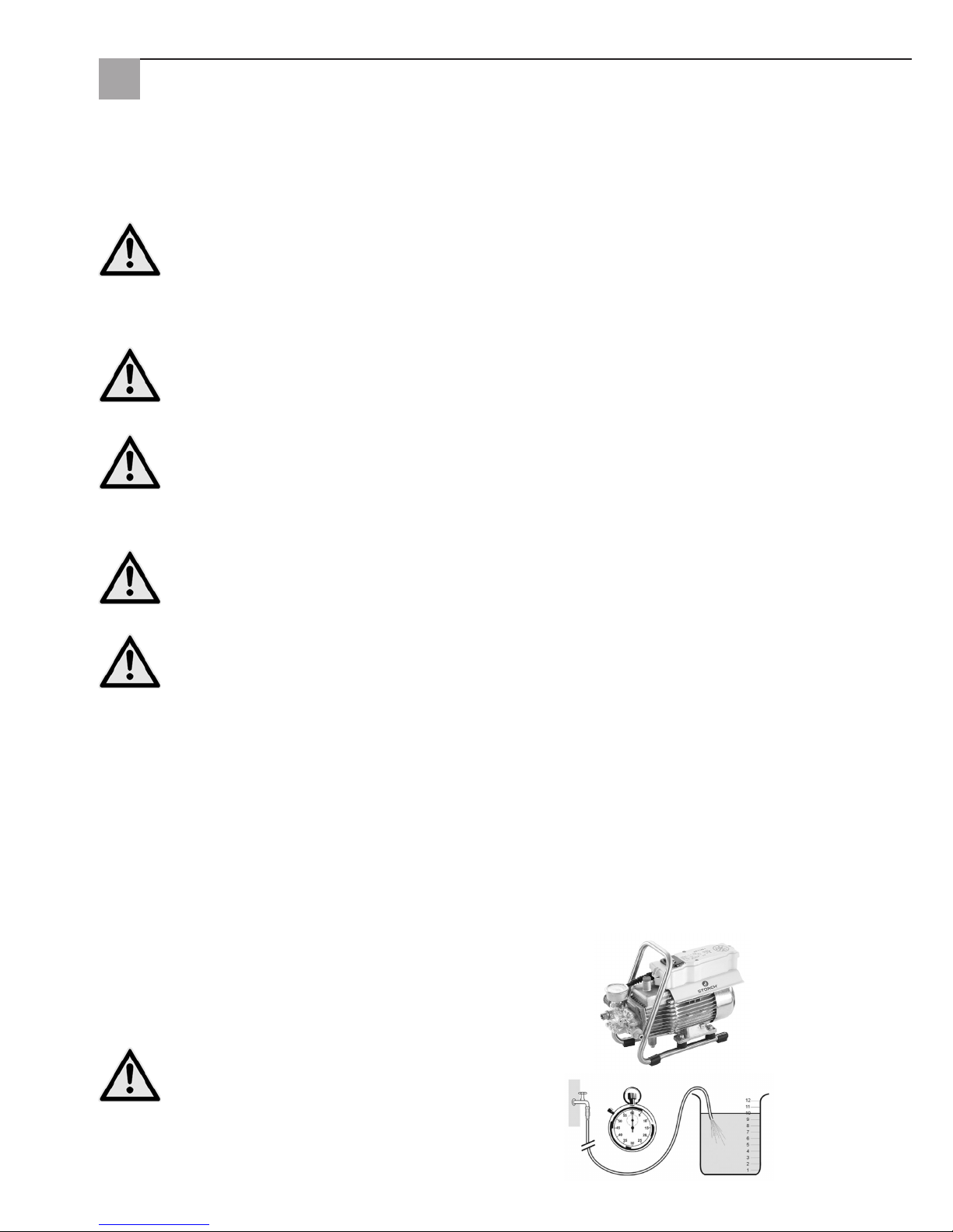
Veuillez vérifier si la quantité d'eau (litres par minute)
indiquée en page 3 (Données techniques) est disponible
pour le nettoyeur haute pression.
Contrôle : laisser s'écouler le tuyau d'amenée
d'eau dans le seau pendant 1 minute. La
quantité d'eau doit au moins correspondre à
l'indication figurant en page 27 !
Un manque d'eau entraîne une usure rapide du joint (pas
de garantie).
Disjoncteur-protecteur de moteur
Le moteur est protégé contre les surcharges par un disjoncteur-protecteur de moteur. En cas de surcharges, celui-ci
éteint le moteur. En cas d'arrêt répété du moteur par le disjoncteur-protecteur du moteur, supprimer la cause du dérangement (voir page 7/8).
Les remplacements et les travaux de contrôle doivent uniquement être effectués par des personnes compétentes lorsque la machine est débranchée du secteur, à savoir lorsque la fiche d'alimentation est retirée.
Installation
Site
La machine ne doit pas être exploitée dans des locaux présentant des risques d'incendie et d'explosion et ne
doit pas être installée, ni utilisée dans des flaques d'eau. Ne jamais exploiter l'appareil sous l'eau.
ATTENTION :
Ne jamais aspirer de liquides à base de solvants tels que les dilutions de peinture, l'essence, l'huile ou les
liquides similaires. Respecter les indications des fiches des produits supplémentaires. Les joints contenus dans l'appareil ne sont pas résistants aux solvants ! Le brouillard de pulvérisation des solvants est très
inflammable, explosif et toxique.
ATTENTION :
Pendant le fonctionnement avec de l'eau chaude à 60°C, des températures élevées règnent.
Ne jamais saisir l'appareil sans gants de protection.
Raccordement électrique
La machine est livrée avec un câble de raccordement de 5 m comportant une fiche d'alimentation. La prise
femelle doit être insérée dans une prise de courant installée conformément aux spécifications avec conducteur de protection et disjoncteur à courant de défaut FI de 30 mA. La prise femelle doit être protégée par
un fusible à 16 A côté alimentation.
En cas d'utilisation d'une rallonge, celle-ci doit comporter un conducteur de protection qui est raccordé aux connexions
par fiches conformément aux spécifications. Les conducteurs de la rallonge doivent présenter une section transversale
minimum de 2,5 mm². Les connexions par fiches doivent révéler une version protégée contre les projections d'eau et
ne doivent pas reposer sur le sol humide.
Passage électrique
La plage de tension de l'appareil présente un risque électrique pour les hommes et les animaux. Seules des personnes
autorisées sont habilitées à dévisser et / ou à démonter l'appareil.
De même, les réparations et l'entretien doivent exclusivement être exécutés par la Sté. Storch ou des centres SAV
agréés de la Sté. Storch. L'exploitation de l'appareil se fait sous la seule responsabilité et aux risques exclusifs de
l'utilisateur.
Page 29
29
Instructions de service succinctes
Faire fonctionner l'appareil uniquement à l'horizontale !
1. Visser le flexible haute pression avec le pistolet pulvérisateur et l'appareil.
2. Réaliser le raccordement d'eau côté aspiration.
3. Purger l'air de l'appareil (ouvrir et fermer le pistolet pulvérisateur à plusieurs reprises).
4. Etablir le branchement électrique.
5. Mettre l'appareil en route avec le pistolet pulvérisateur ouvert et commencer le processus de lavage.
6. Après avoir terminé le processus de lavage, vider complètement la pompe (sans flexible d'aspiration et de pression
mettre le moteur en service pendant env. 20 secondes).
• Utiliser uniquement de l'eau propre !
• Protéger du gel !
ATTENTION :
Respectez les spécifications de votre entreprise spécialisée dans la distribution d'eau. La machine ne doit pas être
directement raccordée au réseau public d'eau potable suivant la norme EN 61770.
Un branchement de courte durée peut toutefois être toléré selon la DVGW (association allemande technique et scientifique pour le gaz et l'eau) si un clapet anti-retour avec aérateur de tubulure est prévu sur la conduite d'alimentation
d'eau.
Un branchement indirect au réseau public d'eau potable est autorisé au moyen d'une sortie libre conforme à la norme
EN 61770, par exemple par l'intermédiaire d'un réservoir avec vanne à flotteur.
Un raccordement direct à un réseau de conduites qui n'est pas destiné à l'alimentation en eau potable est autorisé.
Conduite flexible haute pression et dispositif de pulvérisation
La conduite flexible haute pression et le dispositif de pulvérisation faisant partie de l'équipement de la machine sont
composés d'un matériau haut de gamme et sont adaptés aux conditions de service de la machine et marqués conformément aux spécifications. Arrivée d'eau maximale 20 m.
En cas de besoin de remplacement, seuls les composants homologués par le fabricant et marqués conformément aux spécifications doivent être utilisés. Les conduites haute pression et les dispositifs de pulvérisation
doivent être raccordés en étant étanches à la pression. La conduite haute pression ne doit pas être renversée, ni tirée excessivement, ni tordue. La condute haute pression ne doit pas être tirée par ses arêtes vives,
sans quoi la garantie perd toute validité.
Eau
Mise en service
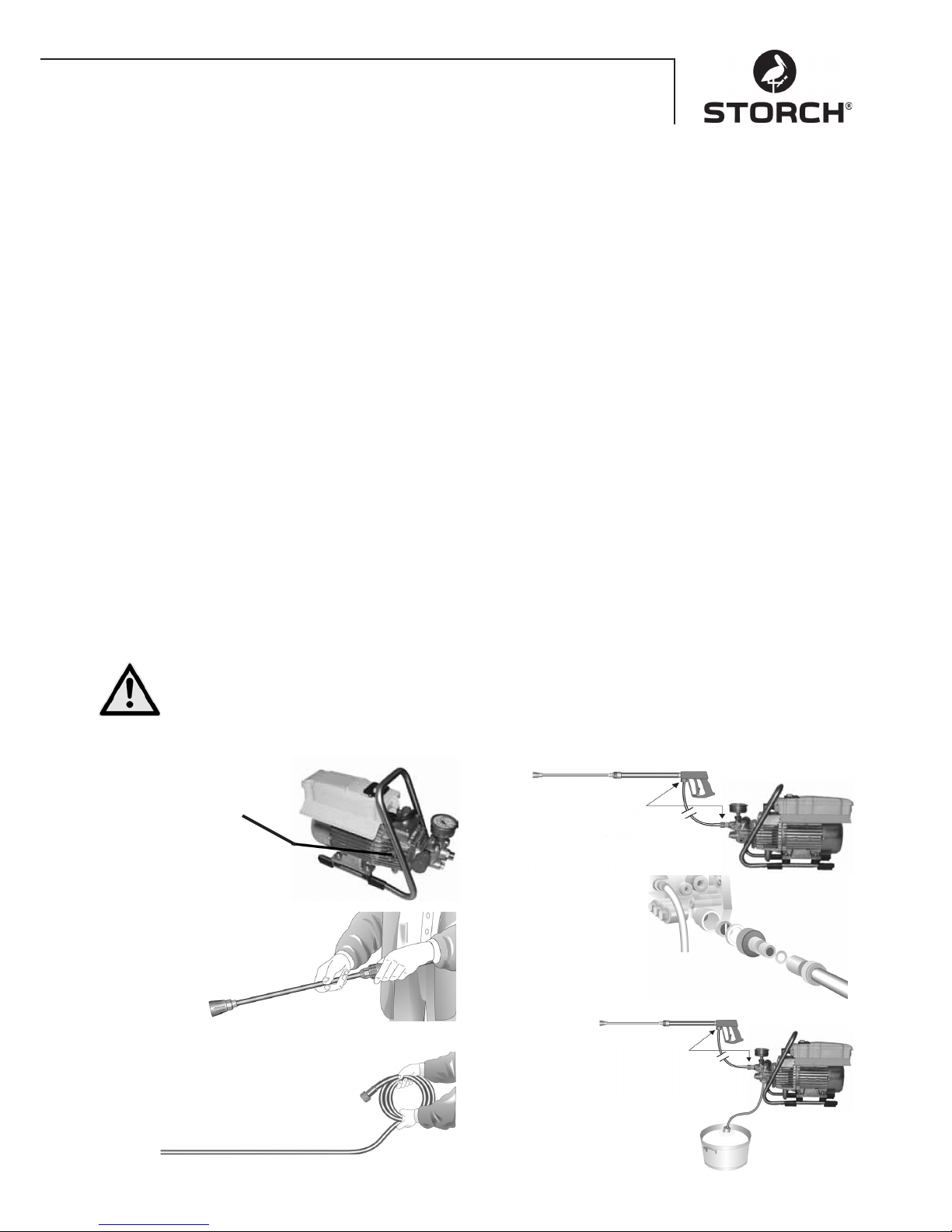
1.
Contrôler le niveau d'huile
L'huile doit être visible
dans le verre-regard
2.
Relier la lance haute pression
au pistolet à main
3.
Dérouler le flexible haute pression sans faire
de boucles et le relier au pistolet à main
autour de la pompe. En cas de
rallonge, utiliser un flexible HD de
20 m max. ou 2 x 10 m avec raccords
de tuyaux.
Liaison du flexible haute
pression avec la lance.
4.
La machine peut être raccordée au
conduit d'eau sous
pression avec de l'eau
froide ou chaude jusqu'à
60° C. En cas d'aspiration
extérieure, veiller à avoir une
eau propre.
Remarque :
Utiliser un filtre d'entrée d'eau réf. art. 65 65 60.
La section transversale du tuyau doit être d'au
moins 1/2“ = 12,7 m (passage libre).
Le tamis n°1 doit toujours être propre.
5.
Hauteur d'aspiration maximale
1,0 m (voir Caractéristiques
techniques, page 27.
Page 30
30
Réglage de la pression
En tournant la poignée de réglage. La pression maximale
est préréglée.
Mise hors service
1. Mettre l'appareil hors service
2. Bloquer l'alimentation en eau
3. Ouvrir brièvement le pistolet jusqu'à ce que la pression soit retombée
4. Verrouiller le pistolet
5. Dévisser le tuyau d'eau et le flexible haute pression
6. Vider la pompe : mettre le moteur en service pendant
env. 20 secondes
7. Débrancher la fiche
8. Hiver : entreposer la pompe dans des locaux hors gel
9. Nettoyer le filtre à eau
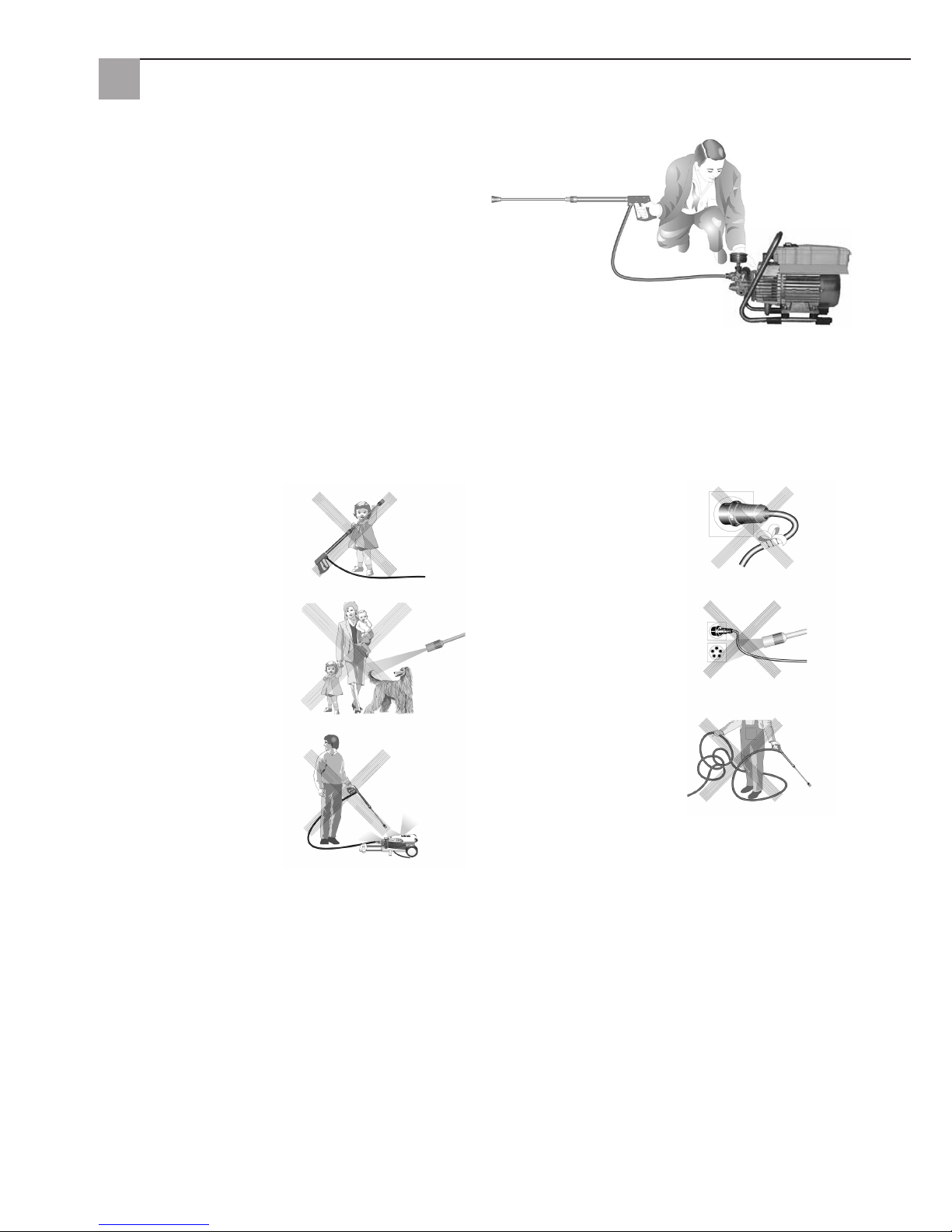
C'est interdit !
Les enfants ne doivent pas
utiliser de nettoyeurs haute
pression !
Ne jamais diriger le jet d'eau
vers des personnes ou des
animaux !
Ne jamais pulvériser l'appareil
avec de la haute pression ou
un jet d'eau !
Ne pas endommager le câble,
ni réparer de façon non conforme !
Ne pas diriger le jet d'eau vers
les prises de courant !
Ne pas tirer le flexible HP
avec des vrilles ou des plis
! Ne pas tirer le flexible audessus d'angles vifs !
Page 31
31
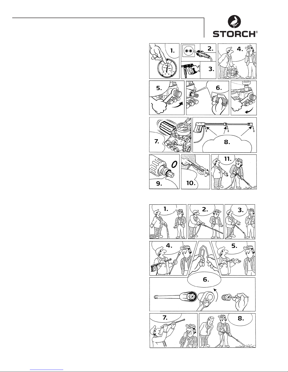
Remédier aux fuites du flexible ou du pistolet
Après la fermeture du pistolet, le manomètre affiche une
pleine pression ! Le régulateur de pression s'allume et
s'éteint constamment !
1. Lorsque le manomètre affiche une pleine pression
2. Débrancher la fiche
3. Comprimer le pistolet pour réduire la pression
4. Enlevez d'abord le flexible
5. Desserrer ensuite en tournant la sortie de la pompe à
l'aide d'une clé plate
6. Nettoyer le corps anti-retour ou remplacer le joint
torique.
7. Le régulateur de pression s'allume et s'éteint constamment en raison de la perte de pression
8. De l'eau peut sortir sur ces trois points. Contrôler les
joints et remplacer, si besoin est, les joints toriques
ou faire contrôler le pistolet par le revendeur
9. Remplacer le joint torique au niveau de la lance ou
du flexible HD
10. Revisser mutuellement le flexible, le pistolet et la
lance
11. Le dérangement est supprimé aussi rapidement
Buse bouchée
Aucune arrivée d'eau, mais le manomètre indique une
pleine pression !
1. Rincer en premier le flexible pour en enlever les résidus
2. Normalement, un jet d'eau puissant apparaît maintenant
3. Si la lance ne fait que goutter,
4. la retirer et nettoyer la buse !
5. Pour la lance à jet plat, seule la buse avant doit être
nettoyée
6. Introduire un objet pointu dans le trou et tirer le capot
vers l'arrière. Plier maintenant correctement un trombone et nettoyer la buse
7. Contrôler d'un coup d'oeil si la buse est nettoyée
8. Cela remarche maintenant aussi bien qu'auparavant
Page 32
32
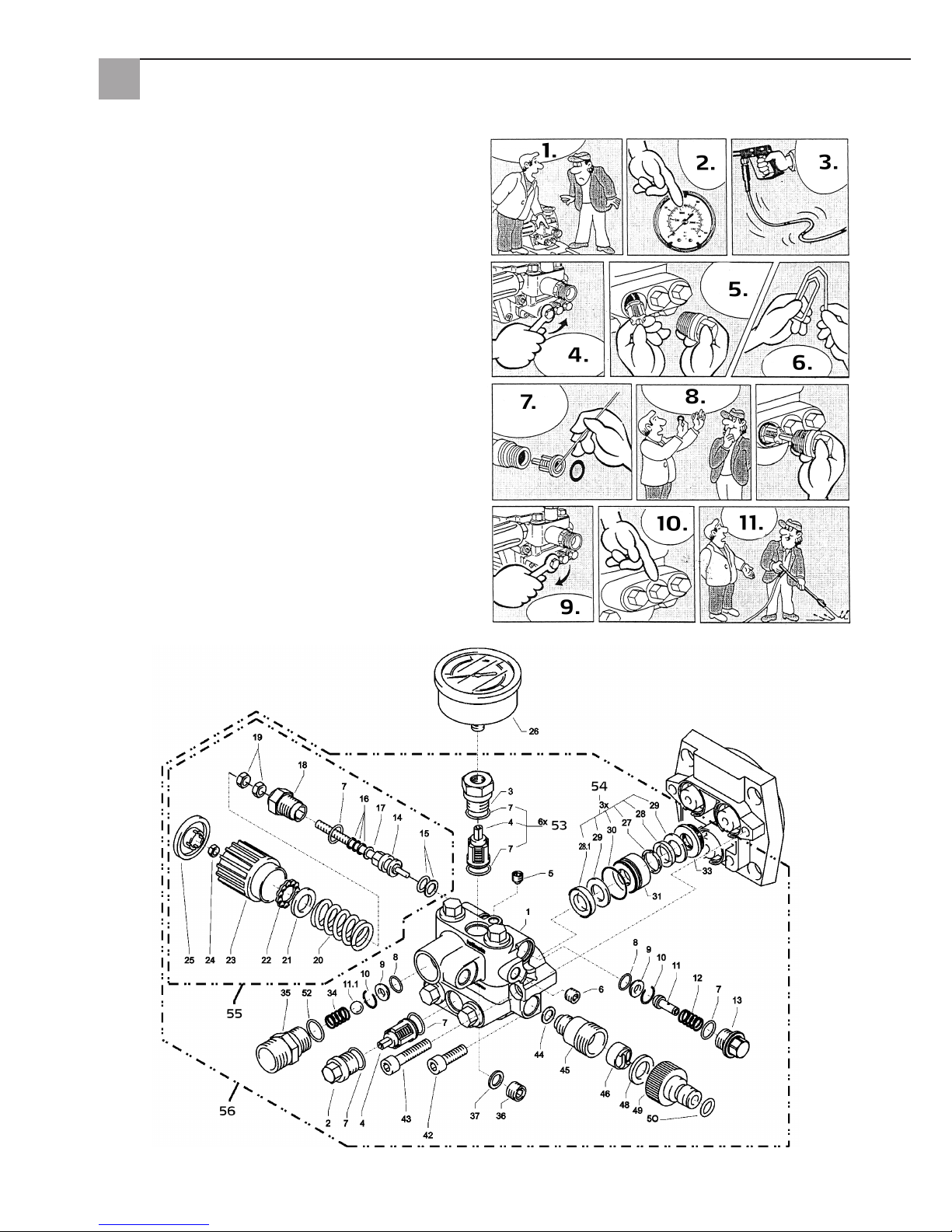
Soupape encrassée ou collée
• le manomètre n'indique pas la pleine pression
• le flexible haute pression vibre
• De l'eau s'échappe par à-coups
• Les vannes peuvent coller si l'appareil n'a pas été utilisé pendant une période prolongée
1. Si une vanne est bouchée,
2. le manomètre indique peu ou pas de pression
3. ou le flexible haute pression vibre
4. Ouvrir la vanne en la tournant avec une clé polygonale
5. et retirer la vis de vanne, la vanne et la bague en
caoutchouc,
6. plier un trombone correctement...
7. et enlevez les saletés de la soupape
• la vanne intérieure doit être fermée
8. De l'eau peut sortir sur ces trois points. Replacer fermement en appuyant le joint en caoutchouc à l'arrière
!
9. Resserrer la vis de vanne
10. ... et répéter pour les six soupapes
11. Le dérangement est supprimé aussi rapidement
Boîtier de vanne
Page 33
33
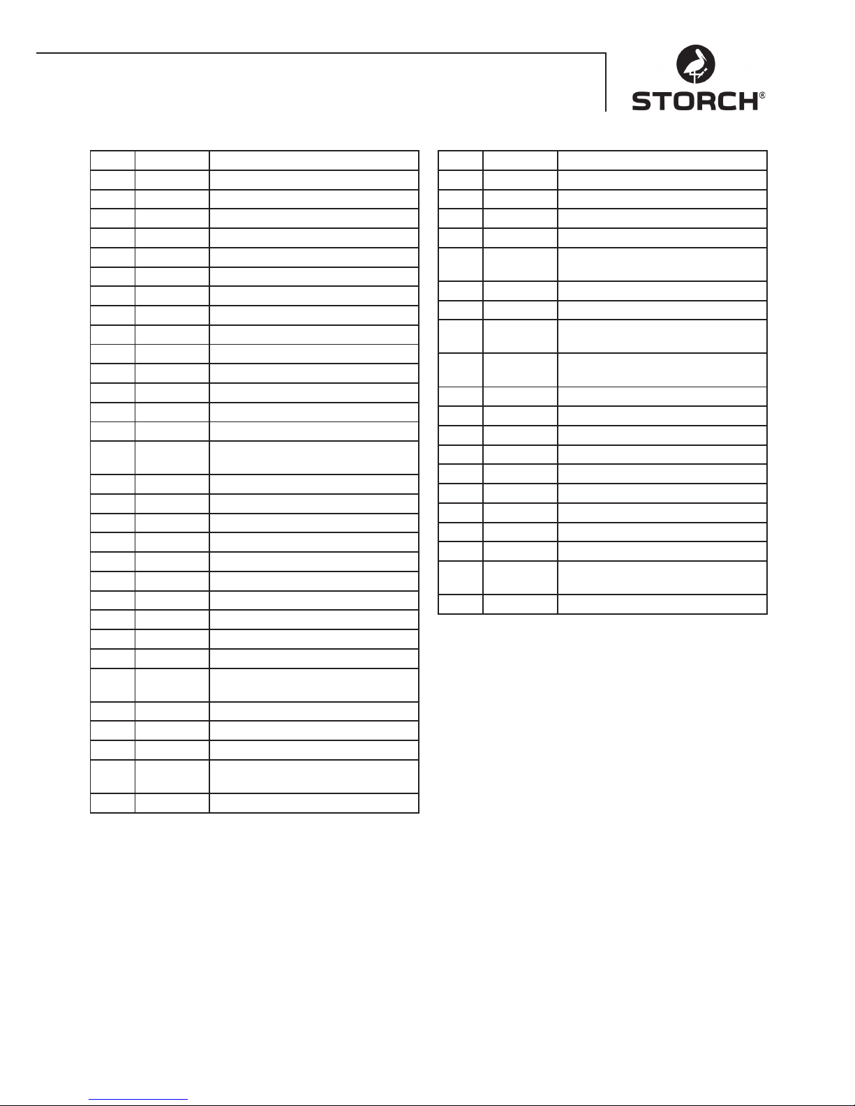
Boîtier de vanne
Pos. Réf. art. Désignation
1 65 62 69 Boîtier de vanne
2 65 62 71 Obturateur de vanne
3 65 62 72 Obturateur de vanne avec R1/4"IG
4 65 63 26 Vanne
5 65 62 74 Obturateur étanche M8 x 1
6 65 62 76 Obturateur étanche M10 x 1
7 65 62 66 Joint torique 12 x 2
8 65 62 77 Joint torique 11 x 1,5
9 65 62 78 Siège en acier inoxydable
10 65 62 79 Bague de sécurité
11 65 62 81 Détendeur de démarrage
11.1 65 62 82 Bille en acier inoxydable 10,0 mm
12 65 62 83 Ressort en acier inoxydable
13 65 62 84 Bouchon fileté
14 65 62 86 Piston de commande 6 mm pour
AZ avec joints
15 65 62 87 Parbaks pour piston 14 mm
16 65 62 88 Parbaks pour colonne 6 mm
17 65 62 89 Rondelle DP
18 65 62 91 Guidage de piston 6 mm
19 65 62 92 Ecrou M6
20 65 62 93 Ressort noir pour pompe AZ
21 65 62 94 Rondelle de pression élastique
22 65 62 96 Roulement à billes
23 65 62 97 Manette M6 pour pompe AZ
24 65 62 98 Ecrou M6 avec SW8
25 65 62 99 Capot pour manette pour pompe
AZ
26 65 63 01 Manomètre
27 65 63 02 Anneau de soutien
28 65 63 03 Manchette 14 x 24 x 5/2,5
28.1 65 63 04 Manchette tissu
14 x 24 x 5/2,5
29 65 63 06 Contre-bague 14 x 24
Pos. Réf. art. Désignation
30 65 63 07 Joint torique 24 x 2
31 65 63 08 Bague antifuite
32 65 63 09 Anneau intermédiaire avec support
33 65 63 11 Ressort de retour
34 65 63 12 Pièce de sortie pour
Clapet de retenue par bille
35 65 63 13 Bouchon de fermeture
36 65 62 37 Bague d'étanchéité en aluminium
42 65 62 63 Vis à six pans creux
M8 x 25 - A2
43 65 63 14 Vis à six pans creux
M8 x 45 - A2
44 65 63 16 Bague d'étanchéité en cuivre
45 65 63 17 Raccord d'aspiration
46 65 61 16 Filtre à eau
48 65 61 17 Bague d'étanchéité en caoutchouc
49 65 61 18 Accouplement à emboîtement
50 65 63 18 Joint torique
52 65 63 19 Joint torique 18 x 2
53 65 63 27 Kit de réparation, vannes
54 65 63 22 Kit de réparation, manchettes
55 65 63 23 Piston de commande intégral avec
manette
56 65 63 28 Boîtier de vanne intégral
Page 34
34
Pistolet avec lance
Pièce d'engrenage
Pos. Réf. art. Désignation
1 65 62 52 Plaque de boîtier
2 65 62 53 Joint étanche à l'huile 14 x 24 x 7
3 65 62 54 Joint torique 83 x 2
4 65 62 56 Ressort plongeur
5 65 62 57 Rondelle de pression élastique 14
mm
6 65 62 58 Plongeur 14 mm AZ-L
7 65 62 59 Circlip 14 mm
8 65 63 31 Plateau oscillant 9,5°
9 65 62 62 Roulement à billes rainuré axial, 3
parties
10 65 62 63 Vis à tête hexagonale M8 x 25
11 65 62 64 Bouchon de vidange d'huile M18 x
1,5 avec aimant
12 65 62 66 Joint torique 12 x 2
13 65 64 33 Regard d'huile
14 65 64 32 Vis de fermeture d'huile rouge
15 65 62 67 Joint couvercle d'huile
16 65 62 68 Couvercle carter d'huile
17 65 60 98 Vis à tête hexagonale M5 x 12
Pos. Réf. art. Désignation
1 65 62 28 Coque de pistolet à droite + à gau-
che
2 65 62 29 Vis 3,5 x 14
3 65 62 31 Kit de réparation poignée du pisto-
let
4 65 65 59 Joint torique ST30 pour tuyau HD
et lance
5 65 62 32 Protection de buse M12 x 1
6 65 62 33 Tube 500 mm
7 65 62 34 Embout ST30 M22 x 1,5/R1/4"
avec ISK
8 65 63 29 Buse à jet plat
9 65 62 37 Bague d'étanchéité en aluminium
sans ill.
65 65 33 Poignée du pistolet HD
Page 35
35
Moteur
Pos. Réf. art. Désignation
1 65 62 38 Collier pour rotor
2 65 62 39 Rotor
3 65 62 41 Capot de ventilateur
4 65 62 42 Boîtier de commutation, partie
inférieure
5 65 63 32 Interrupteur marche/arrêt 12 A
6 65 62 44 Couvercle de commutateur avec
joint
7 65 65 64 Condensateur 40 mycroF
8 65 62 47 Couvercle pour boîtier de commu-
tation
9 65 62 48 Joint pour le couvercle
sans ill.
65 63 33 Moteur complet
sans ill.
65 63 34 Boîtier de commutation complet
Page 36

36
Garantie
Conditions de garantie
Les durées de garantie légales de 12 mois à compter de la date d'achat / de la facture du client final professionnels
s'appliquent à nos appareils. Si nous mentionnons des délais supérieurs dans le cadre d'une déclaration de garantie,
ceux-ci sont mentionnés dans les instructions de service des appareils concernés.
Exercice
Dans un cas couvert par la garantie, nous vous demandons de renvoyer l'appareil complet franco à notre centre logistique à Berka accompagné de la facture ou de l'expédier à une station SAV agréée par nous.
Veuillez contacter préalablement l‘assistance téléphonique de la société STORCH au : +49 800 7 86 72 47
Demande de prise en garantie
Les demandes couvrent exclusivement les défauts de matériau ou de fabrication, en cas d'utilisation conforme de
l'appareil uniquement. Les pièces d'usure, comme les engrenages, les joints d'étanchéité, les pistons, les soupapes
et les paliers, ne sont pas prises en charge par la garantie. Toutes les droits prennent fin suite au montage de pièces
d'autres fabricants, en cas de manipulation et d'entreposage incorrects ainsi qu'en cas de non-respect évident des
instructions de service.
Exécution de réparations
Toutes les réparations doivent exclusivement être réalisées par notre usine ou par des stations de SAV agréées par
STORCH.
Contrôles
La machine doit être contrôlée selon les «Directives pour les projecteurs de liquide» si nécessaire, toutefois au moins
tous les 12 mois, par un expert afin de garantir un fonctionnement sûr. Consigner les résultats du contrôle par écrit. Des
notes informelles suffisent.
Prévention des accidents
La machine est équipée de telle manière que tout accident soit exclu avec une utilisation correcte. Le personnel de
service doit être informé du risque de blessure causé par des pièces chaudes de la machine et le jet haute pression. Les
«Directives pour les projecteurs de liquide» doivent être respectées.
Vidange d'huile
Vor jeder Inbetriebnahme Ölstand am Ölschauglas überprüfen. (Waagerechte Position beachten!) Ölstand sollte bei der
Mitte des Ölschauglases sein. En cas d'humidité de l'air élevée et d'importantes variations thermiques, la formation
d'eau de condensation est possible, l'huile doit ensuite être renouvelée (couleur grise).
Première vidange après environ 50 heures de service. Aucune vidange n'est ensuite nécessaire pendant la durée de vie
de l'appareil. S'il s'avère nécessaire de renouveler l'huile dans le cas d'une réparation ou parce que l'huile présente une
couleur grise, il convient d'ouvrir la vis de vidange d'huile via un réservoir et de vider l'appareil. L'huile doit être récupérée dans un récipient, puis éliminée conformément aux spécifications.
Fuites d'huile
En cas d'échappement d'huile, contacter immédiatement le service après-vente (revendeur) le plus proche. (Préjudices
pour l'environnement, dommages causés à l'engrenage)
Page 37
37
Déclaration de conformité CE
Nom / Adresse de l'exposant : STORCH Malerwerkzeuge & Profigeräte GmbH
Platz der Republik 6-8
D - 42107 Wuppertal
Par la présente, nous déclarons que la machine désignée ci-après
Désignation de la machine : Nettoyeur haute pression 120 bar Compact
Type de machine : Nettoyeur haute pression
satisfait aux dispositions applicables des directives suivantes :
Directive sur les machines : 2006 / 42 / EG
Directive sur la basse tension : 2006 / 95 / CE
Directive européenne
Compatibilité électromagnétique : 2004 / 108 / CE
Directive relative au bruit : 2005 / 88 / CE, art. 13
Machines de sablage à l'eau haute pression
Annexe 3, Partie B, Section 27
Fondé de pouvoir pour la compilation des documents techniques :
STORCH Malerwerkzeuge & Profigeräte GmbH
Platz der Republik 6-8
42107 Wuppertal
Jörg Heinemann
- Gérant -
Wuppertal, 06 - 2013
Page 38

38
IT
Grazie
per la Vostra fiducia nella STORCH. Con l'acquisto avete scelto un prodotto di qualità.
Nel caso abbiate dei suggerimenti per il perfezionamento oppure un problema, saremo lieti di assisterVi.
Contattate il Vostro rappresentante oppure rivolgeteVi direttamente a noi in casi urgenti.
Distinti saluti
STORCH Reparto Assistenza
Tel.: 02 - 66 22 77 15
Indice Pagina
1. Dati tecnici 39
2. Descrizione dell'apparecchio / Funzione 39
3. Sistema acqua e detergente 39
4. Pistola a spruzzo con lancia di lavaggio 40
5. Valvola di regolazione pressione e di ritegno 40
6. Installazione: Luogo di installazione 40
7. Istruzioni in breve 41
8. Messa in funzione 41
9. Regolazione della pressione 42
10. Messa fuori funzione 42
11. Avvertenze di sicurezza 42
12. Aiuto per l'eliminazione di guasti 43 - 44
13. Elenchi dei pezzi di ricambio 44 - 47
14. Controlli 48
15. Garanzia / Condizioni di garanzia 48
16. Dichiarazione di conformità CE 49
Elementi forniti a corredo
Idropulitrice, lancia di lavaggio, tubo flessibile per alta pressione da 10 m, istruzioni per l'uso.
Page 39
39
Dati tecnici
Pressione di esercizio, a regolazione continua 10 - 120 bar
Sovrappressione ammessa 135 bar
Quantità di acqua 10 l / min con 2800 giri / min
Ingresso acqua calda fino a 60° C
Altezza d'aspirazione 1 m
Flessibile per alta pressione 10 m
Valore di allacciamento elettrico 230 V / 50 Hz, 11 A
Potenza 2.500 W
Peso (senza accessori) 18,5 kg
Grandezza ugello 20042
Livello di potenza sonora misurato: 71 dB (A)
garantito: 91 dB (A)
Contraccolpo sulla lancia ca. 27 N
Vibrazioni della lancia 1,9 m/s
2
Descrizione dell'apparecchio / Funzione
1. Ingresso raccordo acqua con filtro
2. Tubo di aspirazione con cestello filtrante (accessorio
speciale)
3. Pompa ad alta pressione
4. Manometro
5. Valvola di regolazione pressione e di ritegno
6. Flessibile per alta pressione
7. Pistola a spruzzo
8. Lancia di lavaggio
acqua
Sistema acqua e detergente
È possibile alimentare la pompa a pressione con acqua
sotto pressione oppure aspirare l'acqua direttamente da
un contenitore senza pressione. Poi, l'acqua sarà diretta
sotto pressione dalla pompa ad alta pressione alla lancia di lavaggio. Il getto ad alta pressione sarà formato
dall'ugello montato alla lancia di lavaggio.
Pistola a spruzzo con lancia di lavaggio
La pistola a spruzzo permette l’azionamento
dell’apparecchio solamente se la leva di sicurezza è in
funzione.
La pistola a spruzzo si apre quando si aziona la leva.
L'acqua sarà poi diretta all'ugello. La pressione di spruzzo
sarà sviluppata e raggiunge in maniera veloce la pressione di esercizio selezionata.
Rilasciando la leva la pistola si chiude, interrompendo
la fuoriuscita di liquido dalla lancia di lavaggio. Il colpo
d’ariete che si verifica alla chiusura della pistola apre la
valvola di regolazione della pressione - valvola di sicurezza e la pompa crea le condizioni di pressione d’esercizio
stabilite per la lancia di lavaggio.
La pistola a spruzzo è un dispositivo di sicurezza Eventuali riparazioni devono essere eseguite solo da personale qualificato. In caso di
necessità di ricambi devono essere solamente
utilizzati dei pezzi di ricambi approvati dal
costruttore.
Valvola di regolazione pressione e di ritegno
La valvola di regolazione pressione e di ritegno protegge la macchina da una sovrappressione troppo alta ed è
costruita in modo da non poter essere impostata oltre la
pressione di esercizio ammessa. Il dado di limitazione del
manico girevole è sigillato con lacca.
La pressione di esercizio e la portata possono essere continuamente impostate azionando il manico girevole.
Sostituzioni, riparazioni, reimpostazioni e sigillature devono essere eseguire solamente da
personale qualificato.
Page 40
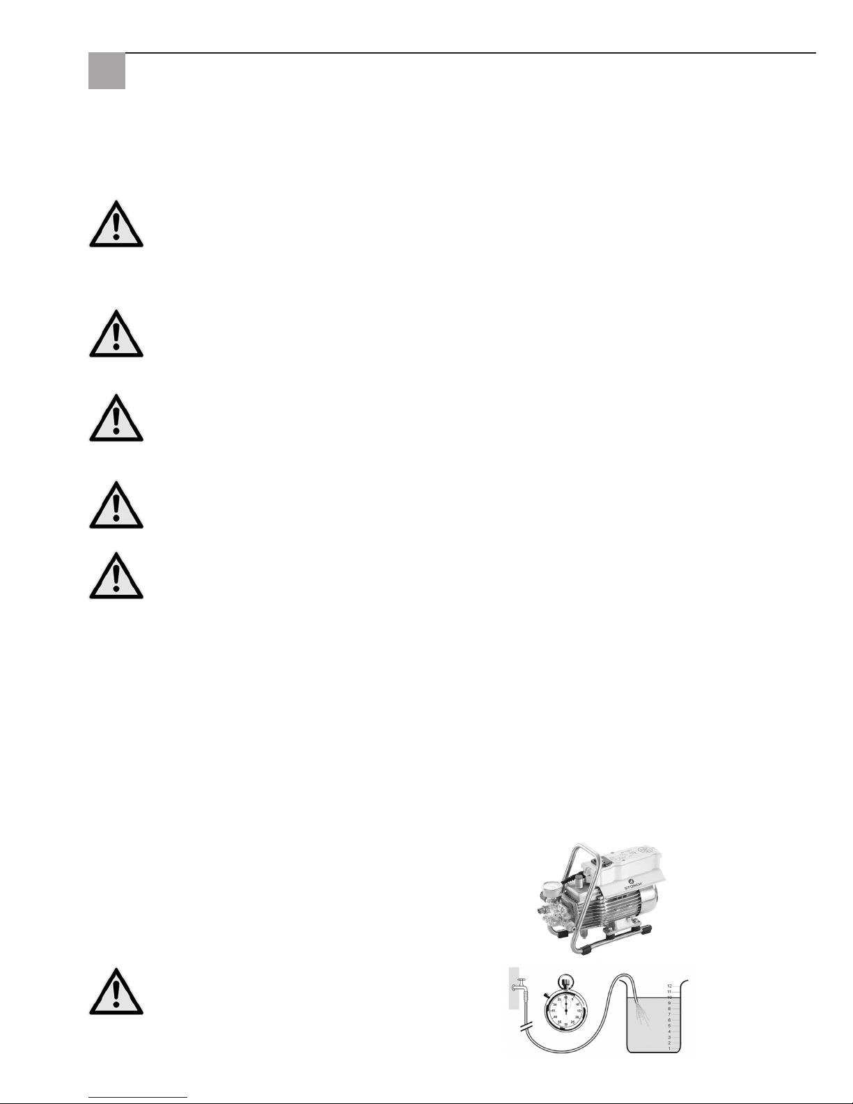
40
Collegamento dell'acqua
Si prega di accertarsi che la macchina pulitrice abbia a
disposizione la quantità di acqua (litri al minuto) riportata
a pagina 39 (dati tecnici).
Controllo: Far agire per 1 minuto nel secchio il tubo flessibile di mandata. La quantità di acqua deve corrispondere
almeno alle indicazione riportate a pagina 39!
Una mancanza d'acqua comporta una rapida
usura della guarnizione (nessuna garanzia).
Interruttore protezione motore
Il motore è protetto da possibili sovraccarichi grazie allo speciale interruttore di protezione. Nel caso di sovraccarico
l’interruttore di protezione spegne il motore. Se il motore viene spento più volte dall’interruttore di protezione risolvere
il problema all’origine (vedasi pagina 7/8).
Sostituzioni e operazioni di verifica devono essere realizzate solamente da persone competenti, con
l’apparecchio scollegato dalla rete elettrica, vale a dire con la spina disinserita.
Sistemazione
Posto
La macchina non deve essere installata ed avviata in locali a rischio di incendio o esplosione come anche in
pozzanghere. L'apparecchio non deve essere utilizzato sott'acqua.
ATTENZIONE:
Mai far aspirare dei liquidi contenenti solventi, benzina, olio o liquidi simili. Osservare le schede informative
degli additivi! Le guarnizioni montate nell'apparecchio non sono resistenti ai solventi! Lo spray di solventi è
altamente infiammabile, esplosivo e nocivo.
ATTENZIONE:
Quando si utilizza dell'acqua con una temperatura di 60° C Vi saranno delle temperature elevate.
Non toccare l'apparecchio senza guanti protettivi.
Allacciamento elettrico
L’apparecchio è fornito di cavo di alimentazione da 5 m e spina elettrica. La spina deve essere inserita in una
presa di corrente installata a norma, con i dovuti sistemi di protezione e con un interruttore di sicurezza per
correnti di guasto da 30 mA. La presa deve avere una portata inerte di 16 A.
In caso d’uso di una prolunga questa deve essere dotata di conduttore di protezione connesso alla spina come da normativa. I conduttori della prolunga devono avere una sezione minima di 2,5 mm². Le spine di attacco devono essere di
tipo antispruzzo e non possono essere lasciati per terra su pavimento bagnato.
Passo sull'elettricità
L'apparecchio ha componenti elettriche che possono comportare un pericolo elettrico per persone ed animali. Esso deve
essere svitato e / oppure smontato solamente da persone autorizzate.
Altrettanto vale per lavori di manutenzione o di riparazione, i quali vanno eseguiti solamente dalla STORCH oppure
presso le service-station con l'autorizzazione da parte di STORCH. L'utilizzo dell'attrezzo avviene sotto la responsabilità
ed a pericolo dell'utente.
Page 41
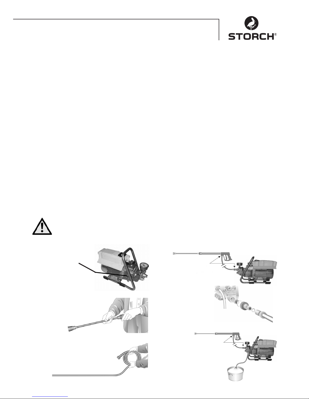
41
Istruzioni in breve
Utilizzare il dispositivo solo in posizione orizzontale!
1. Avvitare flessibile per alta pressione alla pistola a spruzzo e all'apparecchio.
2. Stabilire il collegamento dell'acqua sul lato di aspirazione.
3. Evacuare l'aria dall'apparecchio (chiudere ed aprire più volte la pistola a spruzzo).
4. Stabilire la connessione elettrica.
5. Avviare il dispositivo con la pistola a spruzzo aperta ed iniziare con la fase di lavaggio.
6. Dopo la fase di lavaggio occorre completamente svuotare la pompa (attivare il motore per ca. 20 secondi senza
tubo di aspirazione e di pressione).
• Utilizzare solamente dell'acqua pulita !
• Proteggere dal gelo!
ATTENZIONE:
Osservare le norme dell'azienda di approvvigionamento idrico locale. Ai sensi della norma EN 61770, la macchina non
deve essere collegata all'alimentazione dell'acqua potabile.
Secondo la DVGW (associazione tedesca tecnica e scientifica del gas e dell'acqua), è però ammesso un breve collegamento, se il tubo di alimentazione è dotato di una valvola di ritegno ed un aeratore.
È anche ammesso un collegamento indiretto all'alimentazione dell'acqua potabile pubblica per mezzo di uno scarico
libero secondo EN 61770, ad es. attraverso un contenitore con una valvola a galleggiante.
È ammesso un collegamento diretto ad una rete di approvvigionamento non destinata all'alimentazione dell'acqua potabile.
Tubo flessibile per alta pressione e impianto di spruzzo
Il tubo flessibile per alta pressione ed il dispositivo di spruzzo appartengono all'allestimento della macchina e consistono di materiale di alta qualità, sono adatti per le condizioni di esercizio della macchina e sono contrassegnati in maniera
prescritta. Lunghezza massima del tubo dell'acqua 20 m.
In caso di necessità di ricambi devono essere solamente utilizzati dei pezzi di ricambi contrassegnati in
maniera prescritta ed approvati dal costruttore. Le tubature per alta pressione come anche i dispositivo di
spruzzo devono essere collegati in modo pressurizzato. Il flessibile per alta pressione non deve essere travolto, tirato con eccessiva forza oppure storta. Non tirare il flessibile per alta pressione oltre gli spigoli vivi
altrimenti verrà a mancare la garanzia.
acqua
Messa in funzione
1.
Controllare il livello
dell'olio
L'olio deve essere visibile
nella spia del livello
2.
Collegare la lancia ad alta
pressione con la pistola a mano.
3.
Sbobinare il flessibile per alta pressione senza cappi e
collegarlo con la pistola a mano e la pompa.
In caso di prolunghe, utilizzare un flessibile
per alta pressione con una lunghezza
max. di 20 m oppure 2 flessibili da
10 m e un raccordo per tubi.
Collegamento del tubo
ad alta pressione alla lancia.
4.
Il dispositivo può essere collegato
sia alla condotta d'acqua
fredda ad alta pressione
sia all'acqua calda fino a
60° C. Nel caso si aspiri
acqua da sorgenti esterne,
prestare attenzione che questa sia pulita.
Indicazione:
Utilizzare il filtro ingresso acqua n. art. 65 65 60.
La sezione del
tubo deve essere almeno di 1/2"
= 12,7 mm (passaggio pieno).
Il filtro n. 1 deve sempre essere pulito.
5.
Altezza massima d'aspirazione
1,0 m (vedasi Dati tecnici
a pagina 39.
Page 42
42
Regolazione della pressione
Girando il volantino. La pressione massima è preimpostata.
Messa fuori funzione
1. Spegnere l'apparecchio
2. Bloccare l'alimentazione dell'acqua
3. Brevemente aprire la pistola fino a che la pressione
sia scaricata
4. Bloccare la pistola
5. Svitare il tubo flessibile per l'acqua e il tubo flessibile
per l'alta pressione
6. Svuotare la pompa: Avviare il motore per ca. 20
secondi
7. Staccare la spina
8. Inverno: Immagazzinare in locali protetti dal gelo
9. Pulire il filtro dell'acqua
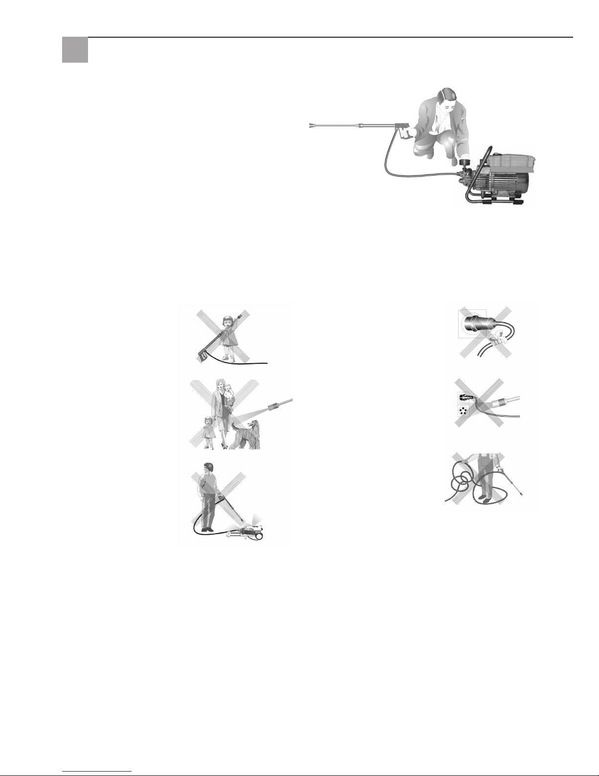
Ciò è proibito !
I bambini non devono utilizzare l’apparecchio per la pulizia ad alta pressione!
Mai dirigere il getto di acqua
verso persone oppure animali.
Non pulire l'apparecchio con
getti d'acqua ad alta pressione!
Non danneggiare il cavo o
ripararlo in maniera inappropriata!
Non orientare il getto d’acqua
in direzione della presa di corrente!
Non tirare il flessibile per alta
pressione si vi sono dei cappi
o delle pieghe! Non tirare il
tubo oltre spigoli vivi!
Page 43
43
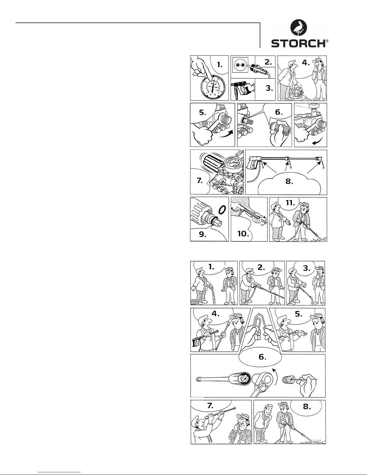
Eliminazione di perdite del tubo flessibile o
della pistola
Dopo la chiusura della pistola il manometro indica la
presenza di una pressione piena! Il regolatore di pressione
si attiva e si disattiva costantemente!
1. Quando il manometro indica una piena pressione
2. Staccare la spina
3. Tirare il grilletto per togliere la pressione dalla pistola
4. Prima rimuovere il tubo flessibile
5. Svitare con una chiave a forcella l'uscita della pompa
6. Pulire il corpo di contraccolpo o sostituire l'o-ring.
7. A causa della perdita di pressione il regolatore di
pressione si attiva e si disattiva costantemente!
8. Questi tre punti sono soggetti a una possibile perdita d'acqua. Controllare le guarnizioni e sostituire gli
o-ring o far controllare la pistola dal venditore
9. Sostituire l'o-ring alla lancia oppure al tubo flessibile
ad alta pressione
10. Ricollegare il tubo flessibile, la pistola e la lancia
11. Si va cosi presto ad eliminare il guasto
Ugello è intasato
Il manometro indica una piena pressione però l'acqua non
fuoriesce!
1. Sciacquare e liberare dai residui il tubo flessibile
2. Di solito, ora dovrebbe fuoriuscire un forte getto
d'acqua
3. Nel caso la lancia goccioli solamente
4. rimuoverla e pulire l'ugello
5. Se si utilizza la lancia con ugello a ventaglio occorre
solamente pulire l'ugello anteriore
6. Infilare un oggetto appuntito nell'apertura e tirare il
cappuccio indietro. Ora piegare un fermaglio e pulire
l'ugello
7. Controllare a vista se l'ugello è pulito
8. Adesso va di nuovo bene come prima
Page 44
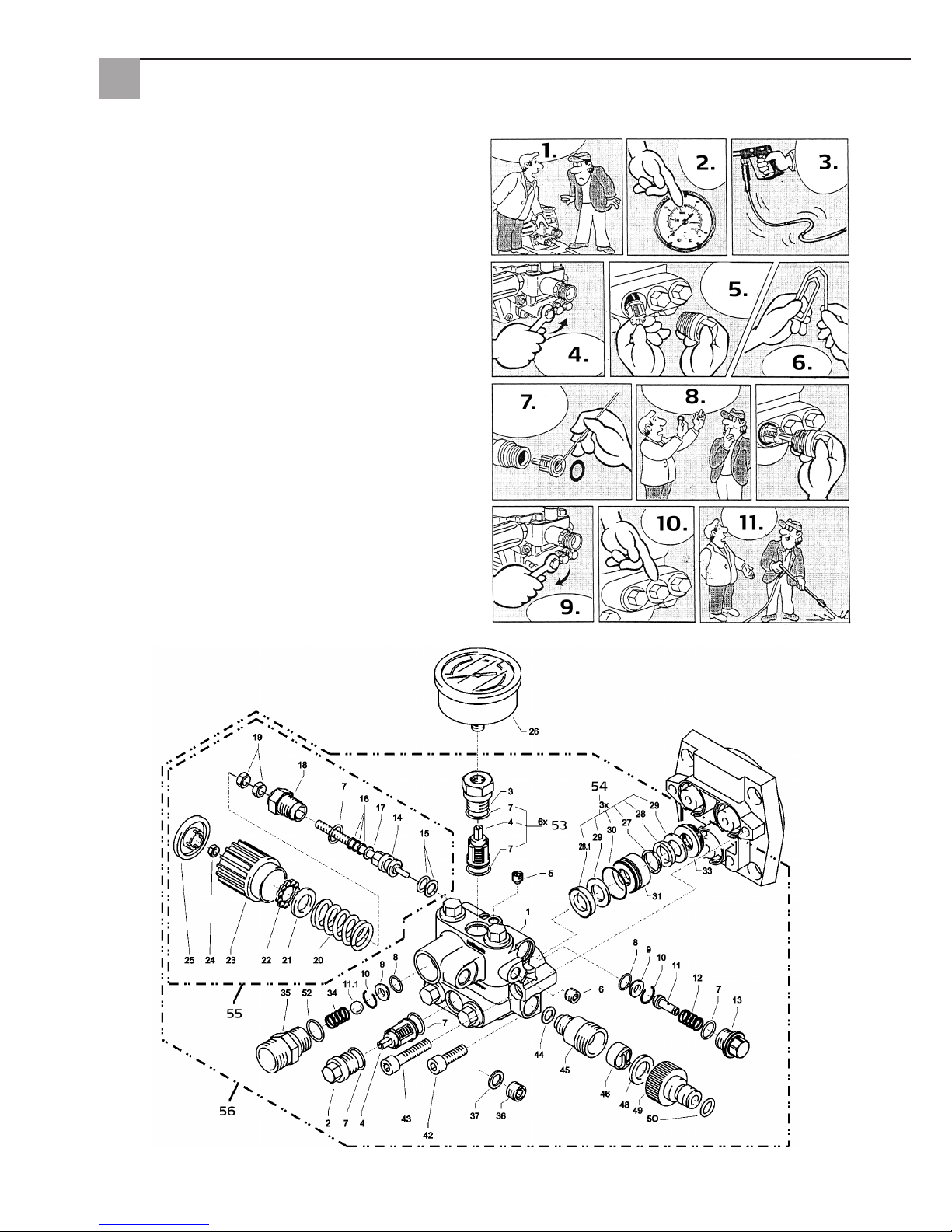
44
Valvola intasato o incollata
• Il manometro indica una pressione insufficiente
• il flessibile per alta pressione vibra
• L'acqua fuoriesce a getti
• Se l'apparecchio non è stato usato per un lungo tempo, le valvole possono incollarsi
1. Nel caso sia otturata una valvola
2. il manometro indica una bassa oppure nessuna pressione
3. oppure il flessibile per alta pressione vibra
4. Aprire la valvola con una chiave ad anello
5. ed estrarre la vite della valvola, la valvola e l'anello
in gomma
6. piegare un fermaglio ...
7. e rimuovere la sporcizia dalla valvola
• la valvola deve essere chiusa all'interno
8. Questi tre punti sono soggetti a una possibile perdita d'acqua. Fortemente riapplicare la guarnizione in
gomma sul retro!
9. serrare la vite della valvola
10. ... e ripetere per tutte le sei valvole
11. Si va cosi presto ad eliminare il guasto
Corpo della valvola
Page 45
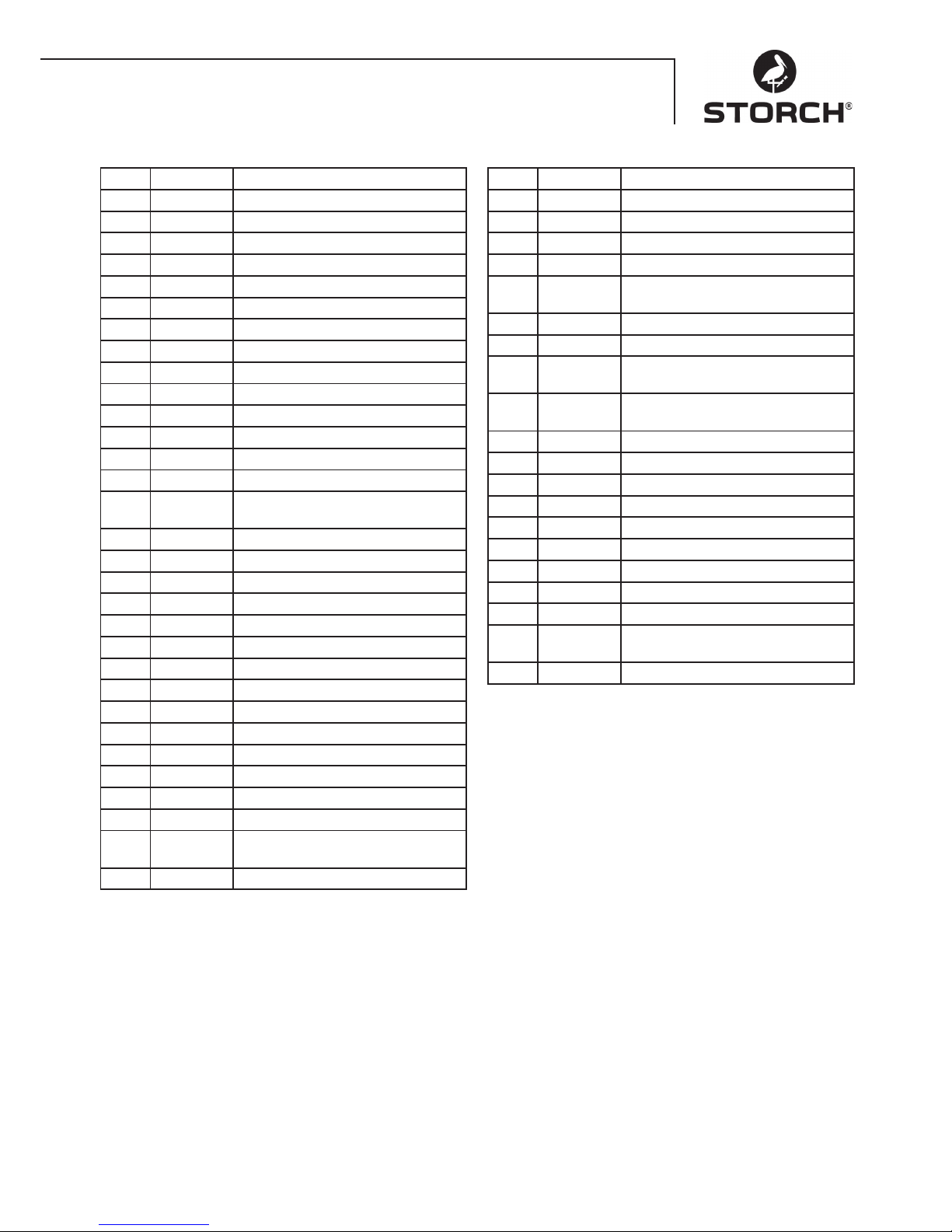
45
Corpo della valvola
Pos. N. art. Descrizione
1 65 62 69 Corpo della valvola
2 65 62 71 Tappo valvola
3 65 62 72 Tappo valvola con R1/4" FI
4 65 63 26 Valvola
5 65 62 74 Tappo ermetico M 8 x 1
6 65 62 76 Tappo ermetico M 10 x 1
7 65 62 66 Guarnizione circolare 12 x 2
8 65 62 77 Guarnizione circolare 11 x 1,5
9 65 62 78 Supporto in acciaio inox
10 65 62 79 Anello di sicurezza
11 65 62 81 Valvola partenza a vuoto
11.1 65 62 82 Sfera in acciaio inox 10,0 mm
12 65 62 83 Molla in acciaio inox
13 65 62 84 Tappo a vite
14 65 62 86 Pistone di comando 6 mm con
guarnizioni
15 65 62 87 Parbak per stantuffo 14 mm
16 65 62 88 Parbak per mandrino 6 mm
17 65 62 89 Rondella MS
18 65 62 91 Guida del pistone 6 mm
19 65 62 92 Dado M6
20 65 62 93 Molla nera per pompa
21 65 62 94 Rondella di spinta della molla
22 65 62 96 Cuscinetto a sfere
23 65 62 97 Volantino M6 per pompa
24 65 62 98 Dado M6 con SW8
25 65 62 99 Cappuccio per volantino pompa
26 65 63 01 Manometro
27 65 63 02 Anello di supporto
28 65 63 03 Anello di tenuta 14 x 24 x 5/2,5
28.1 65 63 04 Anello di tenuta in tessuto
14 x 24 x 5/2,5
29 65 63 06 Back ring 14 x 24
Pos. N. art. Descrizione
30 65 63 07 Guarnizione circolare 24 x 2
31 65 63 08 Guarnizione
32 65 63 09 Anello intermedio con supporto
33 65 63 11 Molla di ritorno
34 65 63 12 Corpo di
contraccolpo
35 65 63 13 Tappo di chiusura
36 65 62 37 Anello di tenuta in alluminio
42 65 62 63 Vite ad esagono incassato
M8 x 25 - A2
43 65 63 14 Vite ad esagono incassato
M8 x 45 - A2
44 65 63 16 Anello di tenuta in rame
45 65 63 17 Bocchettone di aspirazione
46 65 61 16 Filtro dell'acqua
48 65 61 17 Anello di tenuta in gomma
49 65 61 18 Giunto ad innesto
50 65 63 18 Guarnizione circolare
52 65 63 19 Guarnizione circolare 18 x 2
53 65 63 27 Kit di riparazione per valvole
54 65 63 22 Kit di riparazione anelli di tenuta
55 65 63 23 Stantuffo di comando completo
con volantino
56 65 63 28 Corpo della valvola completo
Page 46
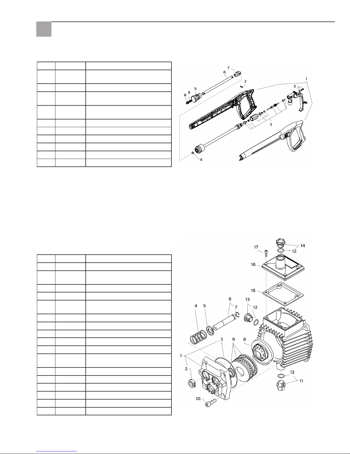
46
Pistola con lancia
Parte dell'ingranaggio
Pos. N. art. Descrizione
1 65 62 52 Piastra dell'alloggiamento
2 65 62 53 Guarnizione di tenuta d'olio 14 x
24 x 7
3 65 62 54 Guarnizione circolare 83 x 2
4 65 62 56 Molla della biella
5 65 62 57 Rondella di spinta della molla 14
mm
6 65 62 58 Stantuffo 14 mm
7 65 62 59 Anello di sicurezza 14 mm
8 65 63 31 Disco obliquo 9,5°
9 65 62 62 cuscinetto assiale a sfere, 3 pezzi
10 65 62 63 Vite Allen M8 x 25
11 65 62 64 Tappo scarico olio M18 x 1,5 con
magnete
12 65 62 66 Guarnizione circolare 12 x 2
13 65 64 33 Spia livello olio
14 65 64 32 Vite di chiusura olio, rosso
15 65 62 67 Guarnizione tappo dell'olio
16 65 62 68 Coperchio scatola olio
17 65 60 98 Vite Allen M5 x 12
Pos. N. art. Descrizione
1 65 62 28 Metà del corpo della pistola destra
+ sinistra
2 65 62 29 Vite 3,5 x 14
3 65 62 31 Kit di riparazione per manico della
pistola
4 65 65 59 O-ring ST30 per tubo flessibile ad
alta pressione e lancia
5 65 62 32 Protezione ugello M12 x 1
6 65 62 33 Tubo 500 mm
7 65 62 34 Nipplo ST30 M22 x 1,5/R1/4"
8 65 63 29 Ugello a ventaglio
9 65 62 37 Anello di tenuta in alluminio
s. fig.
65 65 33 Manico pistola ad alta pressione
Page 47
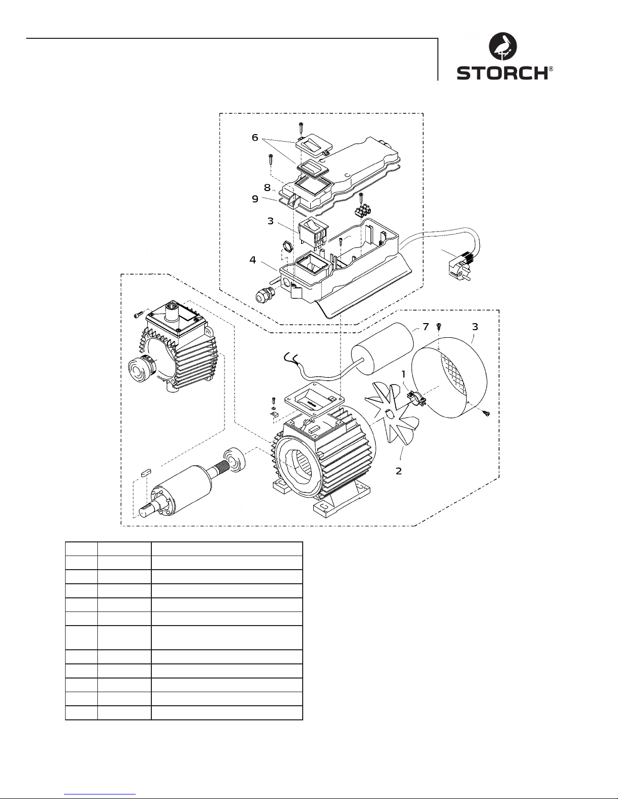
47
Motore
Pos. N. art. Descrizione
1 65 62 38 Morsetto per ventola
2 65 62 39 Ventola
3 65 62 41 Copertura del ventilatore
4 65 62 42 Quadro di comando, parte inferiore
5 65 63 32 Interruttore ON/OFF 12 A
6 65 62 44 Copertura interruttore compr.
guarnizione
7 65 65 64 Condensatore 40 mycroF
8 65 62 47 Coperchio per quadro di comando
9 65 62 48 Guarnizione per coperchio
s. fig.
65 63 33 Motore completo
s. fig.
65 63 34 quadro di comando completo
Page 48

48
Garanzia
Condizioni di garanzia
Per i nostri apparecchi sono applicabili dei periodi di garanzia di 12 mesi a partire dalla data di acquisto / data della
fattura del cliente finale commerciale. Se da parte nostra vengono accordati dei periodi di garanzia più estesi, ciò sarà
riportato separatamente nelle istruzioni per l'uso inerenti ai rispettivi dispositivi.
Rivendicazioni
In casi in cui si intende far valere il diritto di garanzia, Vi preghiamo di inviarci il dispositivo in modo completo con fattura, franco nostro centro di logistica a Berka oppure ad una service-station da noi autorizzata.
Si prega di consultare prima la Hotline di servizio STORCH: Tel.: 02 - 66 22 77 15
Diritto alla garanzia
Il diritti si possono far valere solo per errori di materiale o di produzione nonché esclusivamente in caso di utilizzo
appropriato del dispositivo. Pezzi soggetti all'usura non sono soggetti a diritti di garanzia. Scadranno tutti i diritti in
caso di montaggio di parti di terzi, in caso di maneggio e magazzinaggio improprio come anche in caso di ovvia inosservanza delle istruzioni per l'uso.
Esecuzione di riparazioni
Ogni intervento di riparazione va eseguito esclusivamente nei nostri stabilimenti o presso una service-station autorizzata STORCH.
Controlli
Secondo le "Direttive per i diffusori a getto liquido", la sicurezza del funzionamento della macchina deve essere controllata in caso di necessità però almeno ogni 12 mesi da una persona qualificata. I risultati del controllo devono essere
registrati in scritto. Bastano appunti informi.
Prevenzione degli infortuni
La macchina è allestita in modo che, utilizzandola in maniera regolamentare, saranno esclusi gli infortuni. L'utente
deve essere istruito sul pericolo di lesioni dovute alle parti calde della macchina ed al getto ad alta pressione. Occorre
attenersi alle "Direttive per i diffusori a getto liquido".
Cambio olio
Prima di ogni utilizzo controllare il livello dell’olio nella spia di livello dell'olio. (Rispettare la posizione orizzontale!) Il
livello dell’olio deve essere al centro della spia di livello dell'olio. In caso forte umidità dell’aria ed oscillazioni termiche
è possibile la formazione di condensa, a questo punto è necessario sostituire l’olio (colore grigio).
Il primo cambio dell’olio deve essere eseguito dopo ca. 50 ore di funzionamento. Successivamente non è necessario
alcun cambio d’olio per la durata dell’apparecchio. Nel caso in cui fosse necessario cambiare l’olio, in caso di riparazione o perché l’olio presenta un colore grigio, è necessario aprire la vite di scarico dell’olio su un recipiente e svuotare
l’apparecchio. L'olio deve essere raccolto in un recipiente e smaltito secondo le norme vigenti. Nuovo olio: 0,25 l – olio
per motore W 15/40.
Perdita d'olio
In caso di perdita dell'olio immediatamente rivolgersi al servizio di assistenza (venditore). (danni ambientali, danni
all'ingranaggio)
Page 49
49
Dichiarazione di conformità CE
Nome / indirizzo dell'emittente: STORCH Malerwerkzeuge & Profigeräte GmbH
Platz der Republik 6-8
D - 42107 Wuppertal
Con la presente, noi dichiariamo che la macchina di seguito specificata
Denominazione della macchina: Idropulitrice ad alta pressione 120 bar Compact
Tipo di macchina: Idropulitrice ad alta pressione
corrisponde alle disposizioni pertinenti delle seguenti normative:
Direttiva macchine: 2006 / 42 / CE
Direttiva sulla bassa tensione: 2006 / 95 / CE
Direttiva CE
Compatibilità elettromagnetica: 2004 / 108 / CE
Direttiva sul rumore: 2005 / 88 CE, art. 13
Macchine a getto d'acqua ad alta pressione
Allegato 3, parte B, sezione 27
Procuratore per la composizione della documentazione tecnica:
STORCH Malerwerkzeuge & Profigeräte GmbH
Platz der Republik 6-8
D-42107 Wuppertal
Jörg Heinemann
- Direttore -
Wuppertal, 06 - 2013
Page 50

50
GB
Thank you
for your confidence in STORCH. You have chosen a quality product with this purchase.
If you would like to suggest an improvement, or experience a problem with your product, please do not hesitate to
contact us.
Please speak to your area representative, or in urgent cases, please contact us directly.
Yours sincerely,
STORCH Service Department
Tel: +49 (0)2 02 . 49 20 - 112
Fax: +49 (0)2 02 . 49 20 - 244
Free service hotline: 08 00. 7 86 72 47
Free order hotline: 08 00. 7 86 72 44
Toll-free order fax: 08 00. 7 86 72 43
(only available in Germany)
Table of contents Page
1. Technical data 51
2. Appliance description / Function 51
3. Water and cleaning/care agent system 51
4. Spray gun with wash lance 52
5. Pressure control safety valve 52
6. Installation: Location 52
7. Brief operating guide 53
8. Commissioning 53
9. Pressure settings 54
10. Decommissioning 54
11. Safety precautions 54
12. Troubleshooting aids 55 - 56
13. Spare parts list 56 - 59
14. Tests 60
15. Warranty / warranty conditions 60
16. EC Declaration of Conformity 61
Scope of delivery
High pressure cleaner, 10 m high pressure hose, wash lance, operation manual.
Page 51
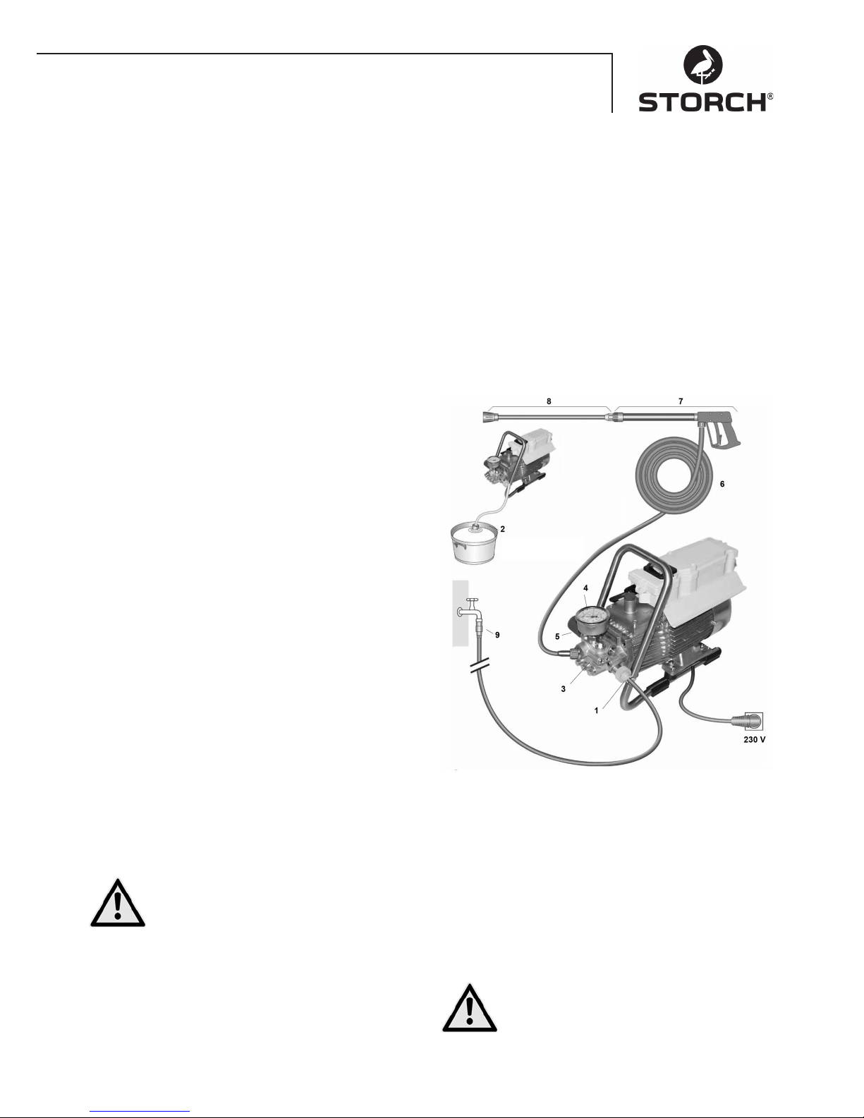
51
Technical specifications
Working pressure, infinitely variable 10 - 120 bar
Permissible overpressure 135 bar
Water volume flow 10 l / min at 2,800 rpm
Hot water infeed up to 60° C
Suction height 1 m
High pressure hose 10 m
Rated load 230 V / 50 Hz, 11 A
Output 2,500 W
Weight (without options) 18.5 kg
Nozzle size 20042
Sound power level measured: 71 dB (A)
warranted: 91 dB (A)
Recoil at lance approx. 27 N
Vibrations at lance 1.9 m/s
2
Appliance description / Function
1. Infeed water coupling with filter
2. Suction hose with filter strainer (optional accessories)
3. High pressure pump
4. Manometer
5. Pressure control valve / safety valve
6. High Pressure Hose
7. Spray gun
8. Spray gun with wash lance
Water
Water and cleaning / care agent system
Water can be fed under pressure to the high pressure
pump, or drafted directly from a non-pressurized container. The water is then fed by the high pressure pump at
pressure to the washing lance. The nozzle on the washing
lance creates a high pressure jet.
Spray gun with wash lance
The spray gun allows operation of the machine only when
the safety shifting lever is actuated.
Actuating the lever opens the spray gun. The water is
then pumped to the nozzle. Spraying pressure is built up
and quickly reaches the selected working pressure.
Releasing the shifting lever closes the gun and prevents
water escaping from the water lance. The pressure surge on closing the gun opens the pressure control safety
valve and the pump feeds water to the wash lance at the
selected working pressure.
The spray gun is a safety appliance. Repairs
must be performed by qualified and authorised
experts. If you need replacement parts, use
manufacturer approved parts only.
Pressure control safety valve
The pressure control/safety valve protects the machine
against impermissible high pressure and is constructed
so that it cannot be set to a level above the permissible
operating pressure. The limiter nut on the wheel is sealed
with lacquer.
You can actuate the wheel to set the working pressure
and injection volume infinitely.
Replacements, repairs, resetting and sealing
must be performed by qualified and authorised
experts.
Page 52
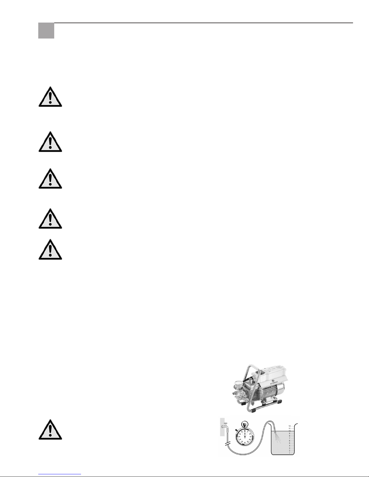
52
Water connection
Please check whether the water flow (litres per minute)
stated on page 51 (Technical Data) is available to the high
pressure cleaner.
Check: Allow the water feed hose to run into a bucket for
1 minute. The water flow must match the specification on
page 3 at a minimum!
A lack of water causes rapid wear on the seal
(not covered by warranty).
Motor protection switch
The motor is protected against overload by a motor protection switch. In event of overload, the motor protection switch
switches off the motor. If the motor keeps on switching off as a result of the motor protection switch, eliminate the
cause (see page 7/8).
Replacement and test work must only be carried out by qualified and authorised experts with the machine
disconnected from the electric network thus, with the mains plug pulled out.
Installation:
Site
The machine must not be run in rooms with a risk of fire or explosion, or positioned and operated in puddles.
Never operate the device in water.
WARNING:
Never draw in fluids containing solvents such as pain thinners, petrol, oil or similar fluids. Observer the
manufacturer's instructions on additives! The seals in the device are not solvent-resistant! The spray from
solvents is highly flammable, potentially explosive and toxic.
WARNING:
High temperatures occur in use with hot water at 60° C.
Do not touch the device without protective gloves.
Electric connection
The machine is supplied with a 5m connecting cable with mains plug. The plug must be be plugged into a
socket that has been installed according to regulations with a 30 mA FI residual current circuit-breaker. The
socket must be secured with a 16 A slow-blow fuse on the mains side.
When using an extension cable, this must be fitted with a circuit breaker that has been connected to the socket according to regulations. The conductor of the extension cable must have a minimum cross-section of 2.5 mm². The plug
connection must be splash-water protected version and must not left laying on a wet floor.
Electrical appliances
The device possesses a voltage range which can pose an electrical hazard to humans and animals. It should only be
unscrewed and / or disassembled by authorised personnel.
Similarly, maintenance and repairs must be performed by STORCH, or by a STORCH-authorised service centre. Use of
the appliance is upon your own responsibility and at your own risk.
Page 53
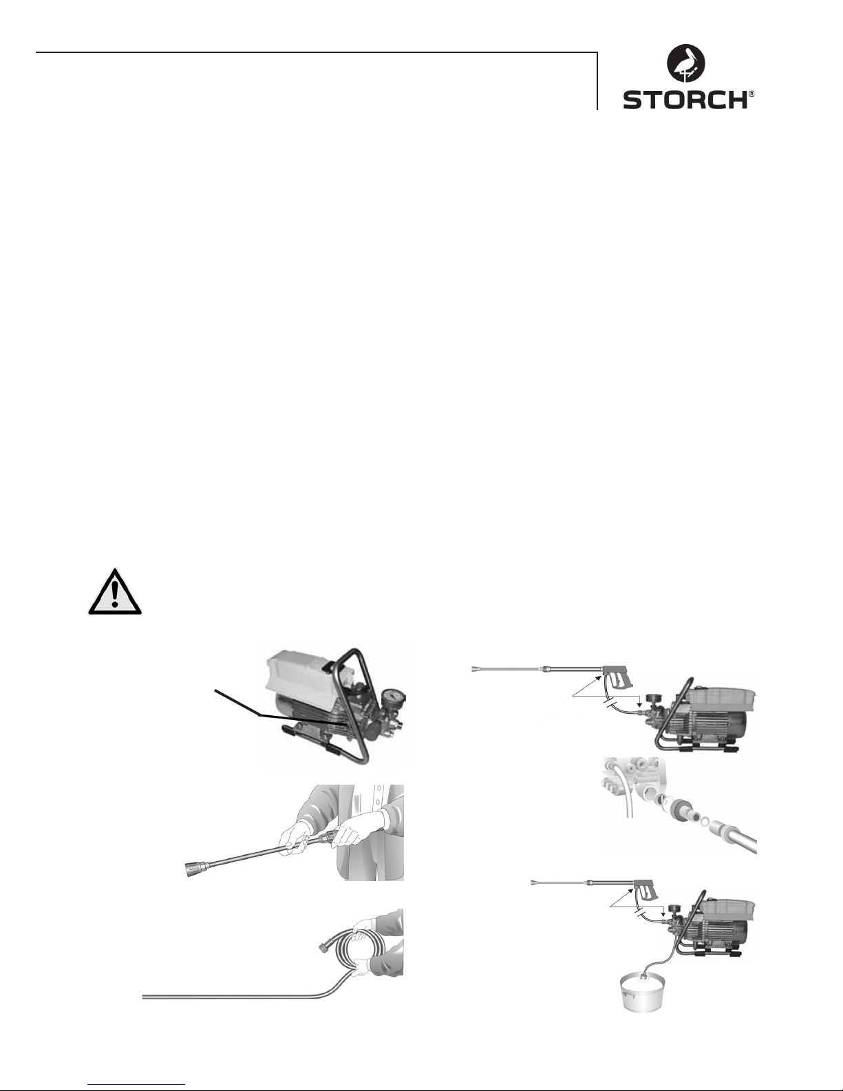
53
Brief operating guide
Only operate the appliance in horizontal position!
1. Connect the screwed connection between the high pressure hose, the spray gun and the appliance.
2. Connect the water supply on the inlet side.
3. Ventilate the device (open and close the spray gun multiple times).
4. Connect to the power supply.
5. Switch on the appliance with the spray gun open and start washing.
6. After completing washing, completely drain the pump (run the engine for approx. 20 sec. with the suction and
pressure hoses disconnected).
• Only use fresh water !
• Protect against frost!
WARNING:
Observe the guidelines of your water supply company. In accordance with EN 61770, the machine must not be connected directly to the public drinking water supply.
According to DVGW (Deutscher Verband des Gas- und Wasserfaches - German Gas and Water Professional Association) a short-term connection is permissible if a backflow preventer and pipe breather are fitted in the inlet line.
It is permissible to connect the device directly to the public drinking water supply using a free run-out in line with EN
61770, Part 4; e.g. using a vessel with a floater valve.
A direct connection to a pipe network not dedicated to providing a public water supply is permissible.
High pressure hose and spraying equipment
The high pressure hose and spraying lance supplied with the machine are made of high quality material, designed for
the operating conditions of the machine and labelled in line with requirements. Maximum water feed line length 20 m.
If you need replacement parts, use manufacturer approved and correctly labelled parts only. High pressure
hoses and the spraying equipment must be connected to be pressure tight. Never drive over the high pressure hose, pull on it excessively or twist the hose. The high pressure hose must not be pulled over sharp edges
to avoid invalidating your warranty.
Water
Commissioning
1.
Check the oil level
Oil must be visible
in the sight glass
2.
Connect the high pressure lance
to the hand gun.
3.
Unroll the high pressure hose avoiding loops
and connect to the hand gun and pump.
If you need to use an extension, use a
high pressure hose with a max. length
of 20 m, or 2 x 10 m with a hose connector.
Connecting the high pressure hose to the lance.
4.
The machine can either
be connected to the
pressurized water line with cold
water, or with water at a temperature
of 60°C. When extracting
outdoors, take care that the
water is clean.
Note:
Water inlet filter Art. no. 65 65 60 is used.
The hose cross-section must be at least
1/2" = 12.7 mm (unobstructed). Strainer
no. 1 must be kept clean at all times.
5.
Maximum suction height 1.0
(refer to the “Technical Data”
on page 51.
Page 54
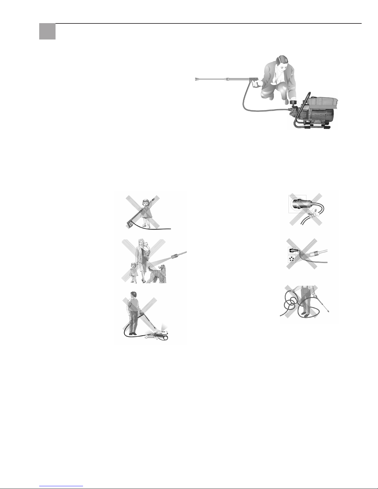
54
Pressure adjustment
By turning the wheel. Maximum pressure is pre-set.
Decommissioning
1. Switch off the device
2. Shut off the water supply
3. Open the gun briefly to relieve the pressure
4. Clean the gun
5. Disconnect the water hose and high pressure hose
6. Drain the pump: run the engine for approx. 20
seconds
7. Disconnect power cord from outlet.
8. Winter: Store the pump in a frost-free room
9. Clean the water filter
That is forbidden!
Children must not work with
the high pressure cleaner!
Never point the water jet at
people or animals!
Never clean the device with
high pressure or a water jet!
Do not damage the cable or
repair incorrectly!
Do not direct the water jet
against sockets!
Never pull the HP hose if it is
looped or kinked! Never pull
the hose over sharp edges!
Page 55
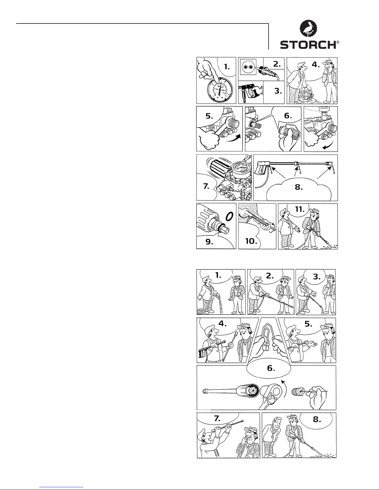
55
Remedying hose or gun leaks
After closing the gun, the manometer shows full pressure! The pressure regulator continually switches on and off!
1. If the manometer shows full pressure
2. Disconnect power cord from outlet.
3. Actuate the gun to relieve the pressure
4. Remove the hose first
5. Use an open-ended spanner to disconnect the hose
from the pump outlet
6. Clean the recoil element or replace the o-ring.
7. Pressure loss causes the pressure regulator to conti-
nually switch on and off!
8. Water can escape at these three points. Check the
seals and replace the o-rings if needed, or take the
gun to your dealer for inspection
9. Replace the o-ring on the lance or on the high pres-
sure hose
10. Reconnect the hose, the gun and the lance
11. This is how quickly you can eliminate the fault
Nozzle Clogged
There is no water, although the pressure gauge indicates
full pressure!
1. Start by flushing the hose to remove any deposits
2. You should see a powerful jet of water
3. If water just drips out of the lance,
4. remove the lance and clean the nozzle!
5. You only need to clean the front nozzle on the flat jet
lance
6. Push a sharp object into the hole and pull back the
cap. Now bend a paperclip to the right shape and use
it to clean the nozzle
7. Visually check if the nozzle is clean
8. You can now continue on as before
Page 56
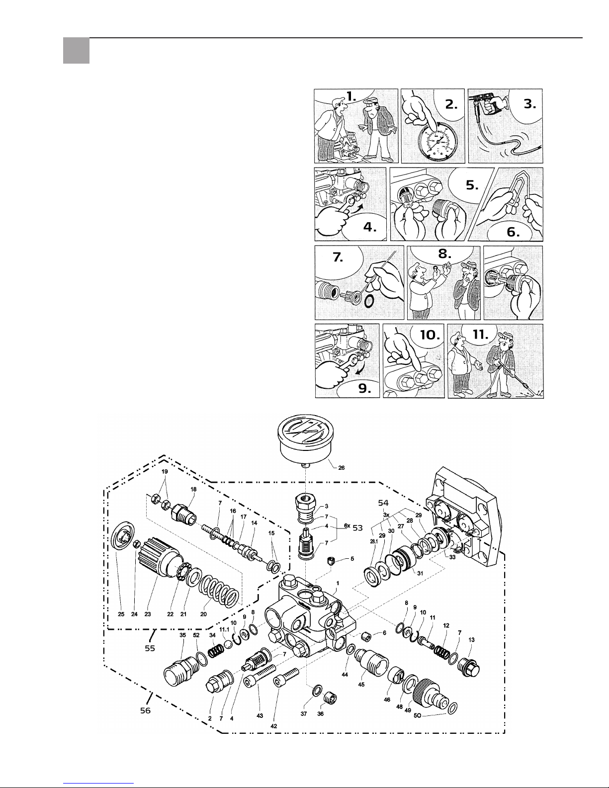
56
Valve soiled or clogged
• Pressure gauge does not show full pressure
• The high pressure hose vibrates
• Water exits intermittently
• Valves can become clogged if you have not used the
device for an extended period
1. If a valve is clogged,
2. the manometer will show little or no pressure
3. or the high pressure hose will vibrate
4. Use a ring spanner to open the valve
5. and remove the valve screw, the valve and the rubber
ring
6. bend a paper clip to the right shape ...
7. and use it to remove the dirt from the valve
• the inside valve must be closed
8. Water can escape at these three points. Push the
rubber seal back in tight
9. re-tighten the valve screw!
10. and repeat this for all 6 valves
11. This is how quickly you can eliminate the fault
Valve housing
Page 57
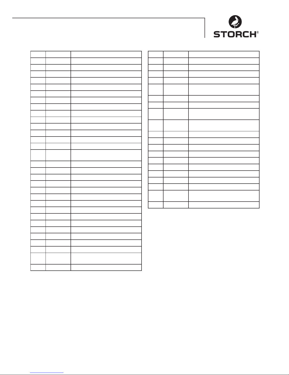
57
Valve housing
Item Art. No. Designation
1 65 62 69 Valve housing
2 65 62 71 Valve plug
3 65 62 72 Valve plugs with R1/4"IG
4 65 63 26 Valve
5 65 62 74 Sealing stopper M 8 x 1
6 65 62 76 Sealing stopper M 10 x 1
7 65 62 66 O-ring 12 x 2
8 65 62 77 O-ring 11 x 1.5
9 65 62 78 Stainless steel seating
10 65 62 79 Circlip
11 65 62 81 Start-up relief valve
11.1 65 62 82 Stainless steel ball 10.0 mm
12 65 62 83 Stainless steel spring
13 65 62 84 Screw plug
14 65 62 86 Steering piston 6 mm for AZ with
seal
15 65 62 87 Parbaks for piston 15 mm
16 65 62 88 Parbaks for spindle 6 mm
17 65 62 89 MS washer
18 65 62 91 Piston guide 6 mm
19 65 62 92 Nut M6
20 65 62 93 Black spring for AZ pump
21 65 62 94 Spring pressure washer
22 65 62 96 Ball bearing
23 65 62 97 Hand wheel M6 for AZ pump
24 65 62 98 Nut M6 SW8
25 65 62 99 Cap for hand wheel AZ pump
26 65 63 01 Manometer
27 65 63 02 Support ring
28 65 63 03 Sleeve 14 x 24 x 5/2.5
28.1 65 63 04 Fabric sleeve
14 x 24 x 5/2.5
29 65 63 06 Back ring 14 x 24
Item Art. No. Designation
30 65 63 07 O-ring 24 x 2
31 65 63 08 Leak ring
32 65 63 09 Intermediate ring with support
33 65 63 11 Rebound spring
34 65 63 12 Outlet part for
ball retaining valve
35 65 63 13 Sealing plug
36 65 62 37 Aluminium - seal ring
42 65 62 63 Hexagon socket head screw
M8 x 25 - A2
43 65 63 14 Hexagon socket head screw
M8 x 45 - A2
44 65 63 16 Copper sealing ring
45 65 63 17 Suction coupling
46 65 61 16 Water filter
48 65 61 17 Rubber sealing ring
49 65 61 18 Plug-in coupling
50 65 63 18 O-ring
52 65 63 19 O-ring 18 x 2
53 65 63 27 Repair kit valves
54 65 63 22 Repair kit sleeves
55 65 63 23 Control piston, complete with hand
wheel
56 65 63 28 Valve housing, complete
Page 58
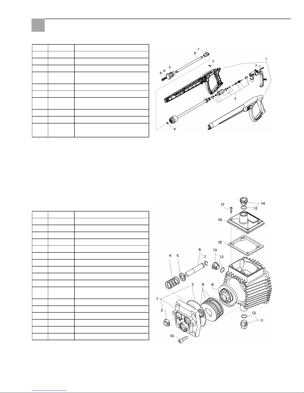
58
Gearbox part
Item Art. No. Designation
1 65 62 52 Housing platen
2 65 62 53 Oil seal 14 x 24 x 7
3 65 62 54 O-ring 83 x 2
4 65 62 56 Plunger spring
5 65 62 57 Spring pressure washer 14 mm
6 65 62 58 Plunger 14 mm AZ-L
7 65 62 59 Retaining ring 14 mm
8 65 63 31 Swash plate 9.5°
9 65 62 62 Axial grooved ball bearing 3-part
10 65 62 63 Hexagon socket screw M8 x 25
11 65 62 64 Oil drain plug M18 x 1.5 with
magnet
12 65 62 66 O-ring 12 x 2
13 65 64 33 Oil sight glass
14 65 64 32 Oil cap red
15 65 62 67 Oil cap seal
16 65 62 68 Cover for oil housing
17 65 60 98 Hexagon socket screw M5 x 12
Item Art. No. Designation
1 65 62 28 Pistol shell half right + left
2 65 62 29 Screw 3.5 x 14
3 65 62 31 Repair kit spray gun handle
4 65 65 59 O-ring ST30 for high pressure
hose and lance
5 65 62 32 Tip guard M12 x 1
6 65 62 33 Pipe 500 mm
7 65 62 34 ST30 Nipple M22 x 1.5/R1/4" with
ISK
8 65 63 29 Flat jet nozzle
9 65 62 37 Aluminium seal ring
Not
illustra-
ted
65 65 33 High pressure spray gun handle
Page 59
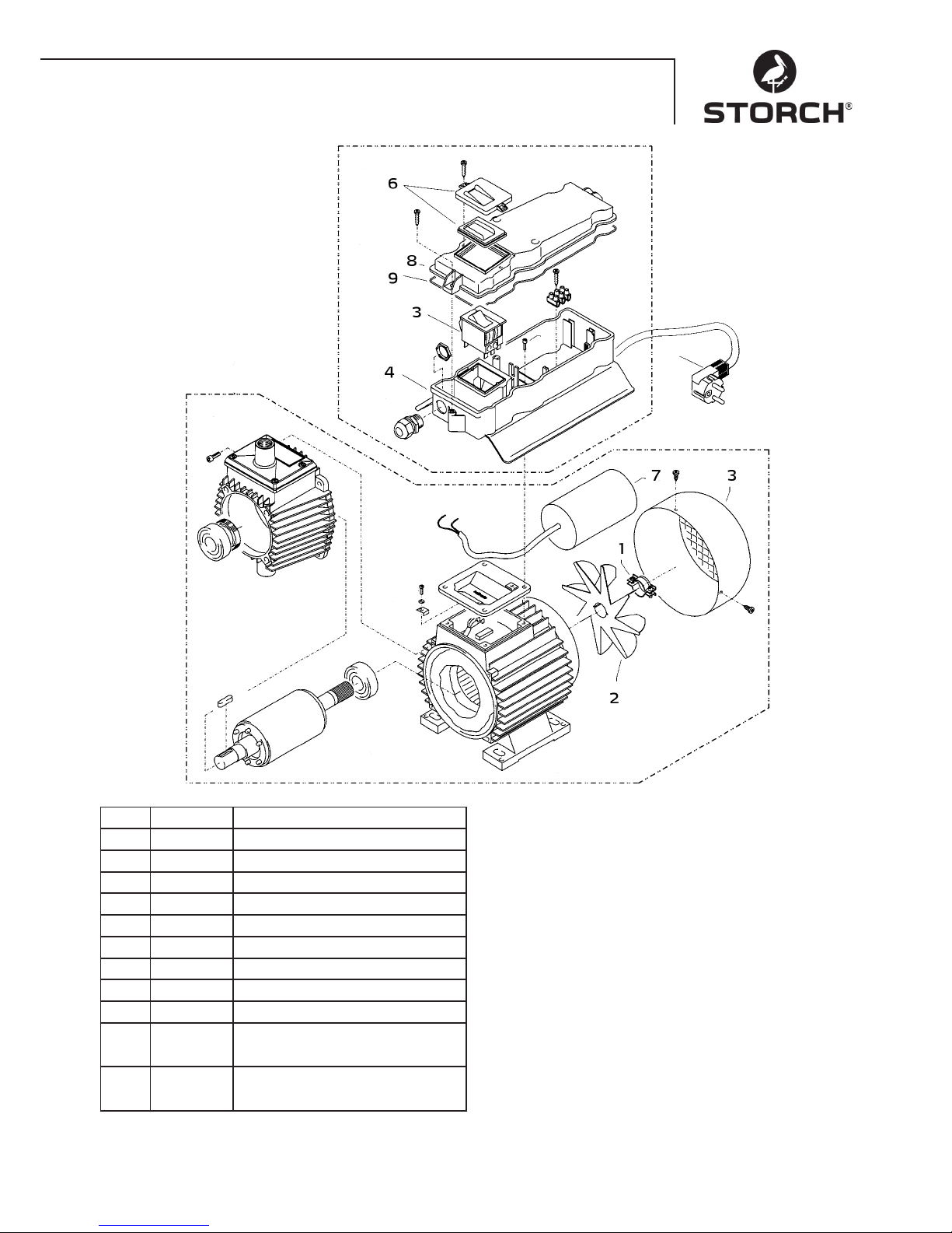
59
Item Art. No. Designation
1 65 62 38 Clamp for impeller
2 65 62 39 Impeller
3 65 62 41 Fan hood
4 65 62 42 Switching unit lower part
5 65 63 32 On/Off switch 12 A
6 65 62 44 Switch cover incl. seal
7 65 65 64 Capacitor 40 mycroF
8 65 62 47 Cover for switch box
9 65 62 48 Seal for cover
Not
illustra-
ted
65 63 33 Complete motor
Not
illustra-
ted
65 63 34 Complete switch box
Page 60

60
Warranty
Warranty conditions
A warranty period of 12 months from the date of purchase/date of invoice applies to our tools for commercial customers. If we have granted an extended warranty period, this period will be noted separately in the operating manual for
the equipment in question.
Claims
If you wish to claim under our warranty or guarantee, please return the complete device and your invoice to our logistics
centre in Berka, postage paid, or send it to one of our authorised service centres.
Please contact STORCH Service-Hotline : 08 00. 7 86 72 47 first.
Your rights under our warranty or guarantee
Claims can only be accepted for material defects or manufacturing errors, and only assuming intended use of the appliance. Wear parts such as drives, seals, pistons, valves and bearings are not covered by such claims. Installation of third
party components, improper use and storage, as well as obvious failure to observe the operating instructions will void
your warranty.
Repairs
All repairs have to be conducted on our premises or by an authorised STORCH service centre.
Tests
The machine must be inspected by an expert every 12 months, in line with the "Regulations for fluid spraying equipment", to ensure that continued safe operation is possible. The results of the inspection must be documented. No specific format is required for the documentation.
Accident prevention
The machine is designed to avoid accidents if used as intended. The operator must be informed of the danger of injury
due to hot machine parts and the high pressure jet. Observe the "Regulations for fluid spraying devices".
Oil change
Before starting up, always check the oil level at the sight glass. (Make sure the appliance is in a horizontal position!)
The oil level should be in the middle of the oil sight glass. In case of high humidity levels and temperature fluctuations,
some condensate may form; you must change the oil in this case (grey colour).
First oil change after approx. 50 hours of operation. Following this, no oil change is required for the appliance's service
life. If you need to change the oil to perform repairs, or because the oil colour is grey, open the oil drain screw above a
catchment tray and drain the appliance. Use a catchment tray to catch the oil, and dispose of the oil in line with legal
requirements. New oil: 0.25 l - engine oil W 15/40.
Oil leaks
If oil escapes, immediately contact your local customer service (dealer). (Environmental damage, transmission damage)
Page 61
61
EC Declaration of Conformity
Name / Address of issuer: STORCH Malerwerkzeuge & Profigeräte GmbH
Platz der Republik 6 - 8
D-42107 Wuppertal
We hereby declare that the following machine
Designation of the machine: High pressure cleaner 120 bar, compact
Machine type: High pressure cleaner
complies with the relevant provisions of the following directives:
Machinery Directive: 2006 / 42 / EC
Low Voltage Directive: 2006 / 95 / EC
EC directive
on Electromagnetic Compatibility: 2004 / 108 / EC
EC Noise Emission Directive: 2005 / 88 EC, Art. 13
High pressure water jet machines
Annex 3, Part B, Section 27
Representative authorised to compile the technical documentation:
STORCH Malerwerkzeuge & Profigeräte GmbH
Platz der Republik 6 - 8
D-42107 Wuppertal
Germany
Jörg Heinemann
- Managing Director -
Wuppertal, 06 - 2013
Page 62

62
CZ
Děkujeme Vám
za důvěru ve firmu STORCH. S nákupem výrobku jste se rozhodli pro kvalitní produkt.
Pokud přesto máte podněty na zlepšení nebo možná nějaký problém, velmi rádi o Vás uslyšíme.
Promluvte si s příslušným externím spolupracovníkem naší firmy nebo se v naléhavých případech obracejte přímo na
nás.
S přátelským pozdravem
Servisní oddělení STORCH
Telefon: +49 (0)2 02 . 49 20 - 112
Fax: +49 (0)2 02 . 49 20 - 244
bezplatná linka Hotline - servis: +49 800. 7 86 72 47
bezplatná linka Hotline - objednávky: +49 800. 7 86 72 44
bezplatný fax - objednávky: +49 800. 7 86 72 43
(pouze v Německu)
Obsah Strana
1. Technické údaje 63
2. Popis přístroje / funkce 63
3. Systém vhodný pro vodu a čistící - údržbové prostředky 63
4. Stříkací pistole s mycí tryskou 64
5. Tlakový pojistný a regulační ventil 64
6. Umístění: stanoviště 64
7. Stručný provozní návod 65
8. Uvedení do provozu 65
9. Nastavení tlaku 66
10. Ukončení provozu 66
11. Bezpečnostní pokyny 66
12. Pomoc při odstraňování poruch 67 - 68
13. Seznamy náhradních dílů 68 - 71
14. Zkoušky 72
15. Záruka / Záruční podmínky 72
16. Prohlášení o shodě ES 73
Rozsah dodávky
Vysokotlaké čistící zařízení, vodní tryska, 10 m vysokotlaká hadice, návod k obsluze.
Page 63
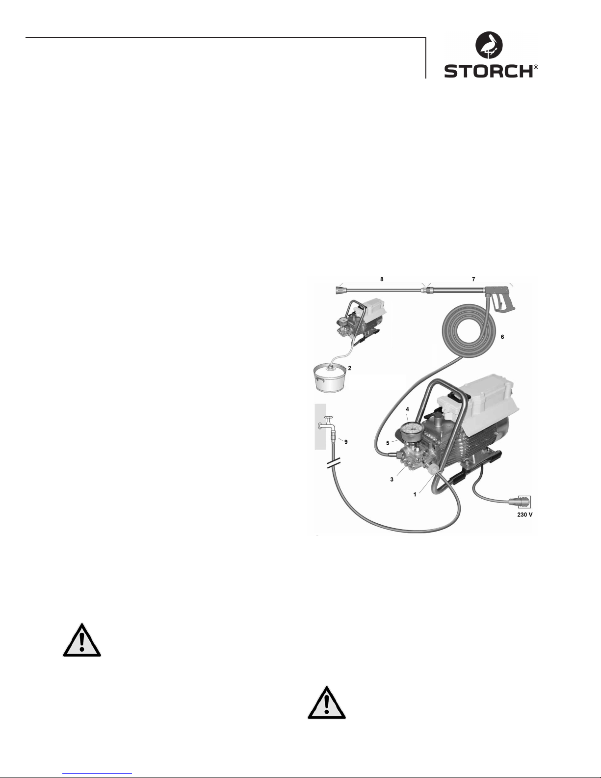
63
Technické údaje
Pracovní tlak, plynule regulovatelný 10 - 120 barů
Přípustný přetlak 135 barů
Výkon vody 10 l / min při 2.800 ot / min
Přívod teplé vody do 60° C
Sací výška 1 m
Vysokotlaká hadice 10 m
Elektrický příkon 230 V / 50 Hz, 11 A
elektrický výkon 2.500 W
Hmotnost (bez příslušenství) 18,5 kg
Velikost trysky 20042
Hladina akustického výkonu měřeno: 71 dB (A)
garantováno: 91 dB (A)
Zpětný ráz u trysky cca 27 N
Vibrace u trysky 1,9 m/s
2
Popis přístroje / funkce
1. Přívod připojení vody s filtrem
2. Sací hadice s filtračním sítkem (zvláštní příslušenství)
3. Vysokotlaké čerpadlo
4. Tlakoměr
5. Tlakový regulační ventil – bezpečnostní ventil
6. Vysokotlaká hadice
7. Stříkací pistole
8. Mycí tryska
Voda
Systém vhodný pro vodu a čisticí - údržbové
prostředky
Voda může být přiváděna pod tlakem vysokotlakého
čerpadla nebo nasávána přímo z beztlaké nádoby. Poté
je voda přiváděna vysokotlakým čerpadlem pod tlakem
do mycí trysky. Hubicí mycí trysky se vytváří vysokotlaký
paprsek vody.
Stříkací pistole s mycí tryskou
Stříkací pistole umožňuje provoz stroje pouze se stisknutou bezpečnostní přepínací pákou.
Stisknutím páky se stříkací pistole otevře. Voda je pak
dopravována k trysce. Tlak vzroste na špičkový tlak a
rychle dosáhne zvolené hodnoty pracovního tlaku.
Uvolněním spínací páčky se pistole uzavře a tím se
zabrání dalšímu unikání vody z vodní trysky. Tlakový ráz
při uzavírání pistole otevře tlakový pojistný a regulační
ventil a čerpadlo čerpá kapalinu se zvoleným pracovním
tlakem do mycí trysky.
Stříkací pistole je bezpečnostní přístroj, opravy
smí provádět pouze odborníci. V případě nutné
výměny je třeba použít pouze výrobcem schválené konstrukční díly.
Tlakový pojistný a regulační ventil
Tlakový pojistný a regulační ventil chrání stroj před
nepřípustně vysokým přetlakem a je konstruován tak,
aby ho nebylo možné nastavit na vyšší než přípustný
provozní tak. Omezovací matice otočné rukojeti je
zapečetěna lakem.
Použitím otočné rukojeti lze plynule nastavit pracovní
tlak a vystřikované množství vody.
Výměnu, opravy, nové nastavení a lakování
smí provádět pouze odborníci.
Page 64
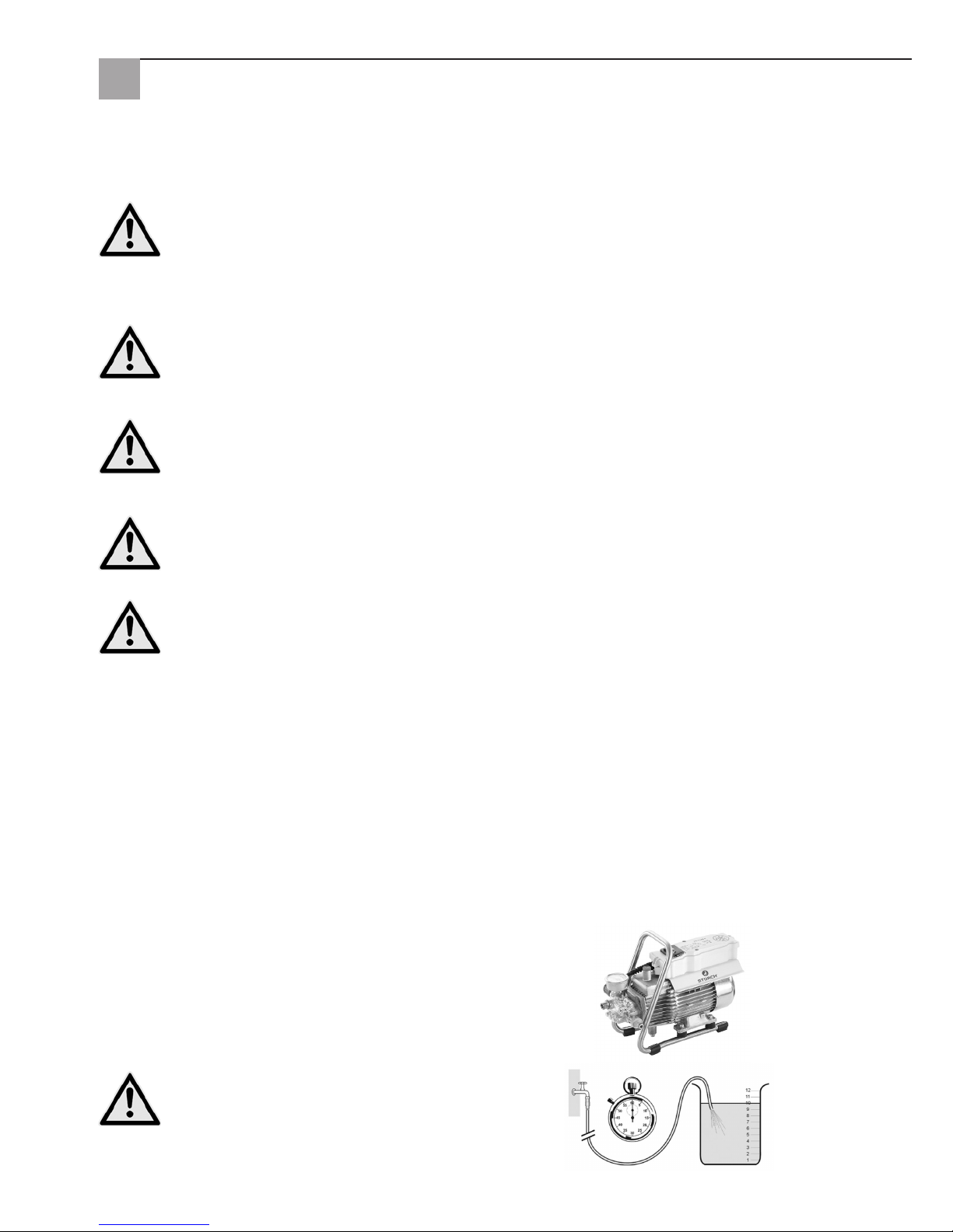
64
Přívod vody
Zkontrolujte prosím, zda je pro vysokotlaké čistící
zařízení k dispozici množství vody (litrů za minutu) uvedené na straně 3 (Technické údaje).
Zkouška: vodu z hadice pro přívod vody nechat 1 minutu
téci do kbelíku. Množství vody musí alespoň odpovídat
ůdajům uvedeným na straně 63!
Nedostatek vody vede k rychlému
opotřebování těsnění (žádná záruka)-
Jistič motoru
Motor je před přetížením chráněn jističem motoru. Při přetížení se jistič motoru rozpojí. Při opakovaném odpojení
motoru vlivem jističe motoru odstraňte příčinu poruchy (viz strana 7/8).
Výměnu a kontroly smí provádět výhradně kvalifikované osoby u stroje odpojeného od elektrické sítě, tzn. s
vytaženou zástrčkou síťového přívodu.
Ustavení
Stanoviště
Stroj nesmí být umístěn a provozován v prostorách ohrožených požárem a výbuchem. Přístroj nesmí být provozován pod vodou.
POZOR:
Nikdy nenasávejte kapaliny obsahující rozpouštědla, například ředěné laky, benzín, olej a podobné kapaliny.
Respektujte údaje v katalogových listech doplňkových prostředků. Těsnění v přístroji nejsou odolná proti
rozpouštědlům! Rozstřikovaná mlha rozpouštědel je hořlavá, výbušná a jedovatá.
POZOR:
Při provozu s vodou, jejíž teplota přesahuje 60 °C, se vyskytují zvýšené teploty.
Přístroje se nedotýkejte bez ochranných rukavic.
Elektrické připojení
Stroj se dodává s 5 m přívodním kabelem se síťovou zástrčkou. Zástrčka musí být zapojena do předpisově
instalované zásuvky s připojeným ochranným vodičem a proudovým chráničem FI 30 mA. Zásuvka musí být
v síti zajištěna pomalu reagující pojistkou 16 A.
Při používání prodlužovacího kabelu musí být prodlužovací kabel vybaven ochranným vodičem, který je předpisově
připojen ke konektorům zásuvných spojů. Vodiče prodlužovacího kabelu musí mít minimální průřez 2,5 mm². Zásuvné
spoje musí být v provedení chráněném před odstřikující vodou a nesmí ležet na mokré podlaze.
Elektropasus
Přístroj má rozsah napětí, od kterého může vzniknout nebezpečí úrazu elektrickým proudem pro lidi a zvířata. Zařízení
smí přimontovat nebo demontovat pouze autorizované osoby.
Stejně tak údržbu a opravy smí provádět pouze firma STORCH nebo autorizované servisní stanice firmy STORCH. Provoz zařízení se uskutečňuje na vlastní zodpovědnost a nebezpečí uživatele.
Page 65
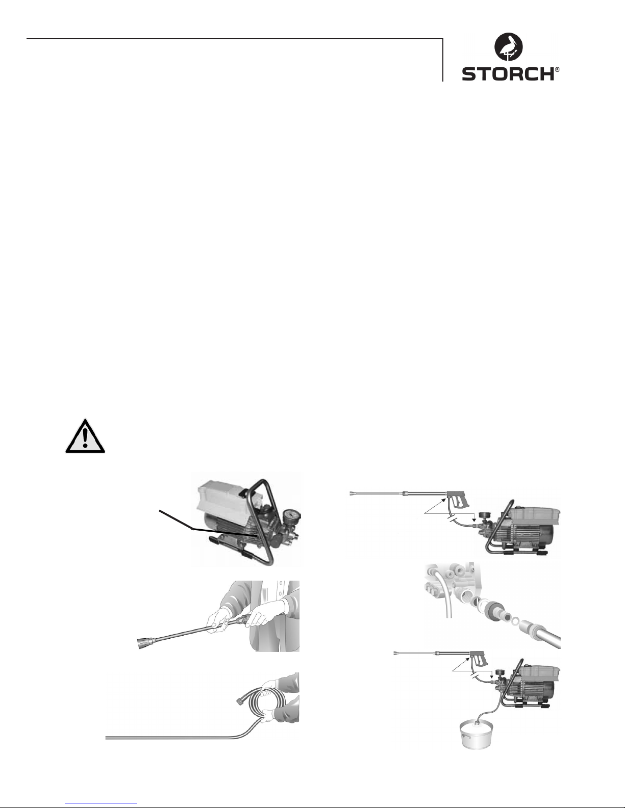
65
Stručný provozní návod
Přístroj provozujte pouze ve vodorovné poloze!
1. Vysokotlakou hadici sešroubujte se stříkací pistolí a přístrojem.
2. Na straně sání vytvořte připojení vody.
3. Přístroj odvzdušněte (stříkací pistoli několikrát otevřete a zavřete).
4. Vytvořte připojení el. proudu.
5. Přístroj zapněte při otevřené stříkací pistoli a začněte s procesem mytí.
6. Po ukončení procesu mytí čerpadlo úplně vyprázdněte (motor zapněte na cca 20 sekund bez sací a tlakové hadice).
• Používejte pouze čistou vodu !
• Chraňte před mrazem!
POZOR:
Respektujte předpisy Vašeho dodavatele vody. Podle normy EN 61770 nesmí být stroj připojen přímo k veřejné vodovodní síti s pitnou vodou.
Podle předpisů německého svazu DVGW (plynařství a vodní instalatérství) je však krátkodobé připojení přípustné,
pokud je do přívodu instalován zpětný ventil se zavzdušňováním přívodu.
Nepřímé připojení k veřejnému zásobování pitnou vodou je přípustné pomocí volného výtoku dle normy EN 61770,
např. použitím nádrže s plovákovým ventilem.
Bezprostřední připojení k vodovodní síti, která není určena k zásobování pitnou vodou, je přípustné.
Vedení z vysokotlakých hadic a stříkací zařízení
Vysokotlaké hadicové vedení a stříkací zařízení, která jsou součástí vybavení stroje, jsou vyrobeny z kvalitního materiálu a jsou optimalizovány na provozní podmínky stroje a také jsou předpisově označeny. Maximální délka přívodního
vedení vody 20 m.
V případě nutné výměny je třeba použít pouze výrobcem schválené a předpisově označené konstrukční díly.
Vysokotlaké hadicové vedení a stříkací zařízení musí být připojena tak, aby byla i po přivedení tlaku těsná.
Je zakázáno přejíždět přes vysokotlaká hadicová vedení, nadměrně za ně tahat nebo je přetáčet. Vysokotlaká hadicová vedení nesmí být vedena přes ostré hrany, jinak zaniká záruka.
Voda
Uvedení do provozu
1.
Zkontrolujte hladinu
oleje
Olej musí být vidět v
průzorovém skle.
2.
Vysokotlakou trysku připojte
na ruční pistoli
3.
Vysokotlakou hadici odviňte tak, aby se netvořily
smyčky a spojte ji s ruční pistolí a
čerpadlem. Při prodlužování použijte
max. 20 m vysokotlaké hadice nebo
2 x 10 m hadice s hadicovými spojkami.
Připojení vysokotlaké hadice k trysce.
4.
Stroj lze volitelně
připojit k přívodu tlakové vody
se studenou vodou nebo s teplou
vodou do teploty 60° C. Při nasávání
vody zvenčí dbejte, aby voda byla čistá.
Upozornění:
Použijte filtr na přívodu
vody obj.č. 65 65 60.
Průřez hadice musí být
minimálně 1/2" = 12,7 mm
(volný průchod). Sítko č. 1 musí být vždy čisté.
5.
Maximální sací výška 1,0 m
(viz Technické údaje strana 63.
Page 66
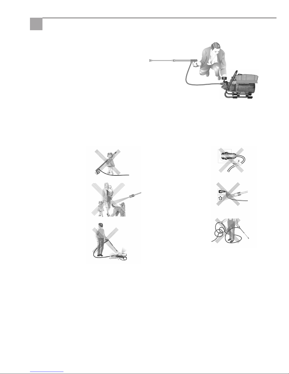
66
Změna nastavení tlaku
Pootočením ručního kolečka. Maximální tlak je předem
nastaven.
Ukončení provozu
1. Vypněte přístroj
2. Uzavřete přívod vody
3. Pistoli krátce otevřete, dokud se neodstraní tlak
4. Pistoli zablokujte
5. Odšroubujte hadici na vodu a vysokotlakou hadici
6. Vyprázdnění čerpadla: Zapněte motor na cca 20
sekund
7. Vytáhněte síťovou zástrčku ze zásuvky!
8. Zima: Čerpadlo skladujte v prostorách bez mrazu
9. Vyčistěte vodní filtr
To je zakázáno!
Je zakázáno, aby s vysokotlakým čistícím zařízením pracovaly děti!
Proud vody nikdy nesměrujte
na lidi ani zvířata!
Přístroj neostřikujte vysokotlakem ani proudem vody!
Kabel nepoškozujte a ani ho
neodborně neopravujte!
Proud vody nikdy nesměrujte
na elektrické zásuvky!
Vysokotlakou hadici netahejte se smyčkami nebo zalomením! Hadici netahejte přes
ostré hrany!
Page 67
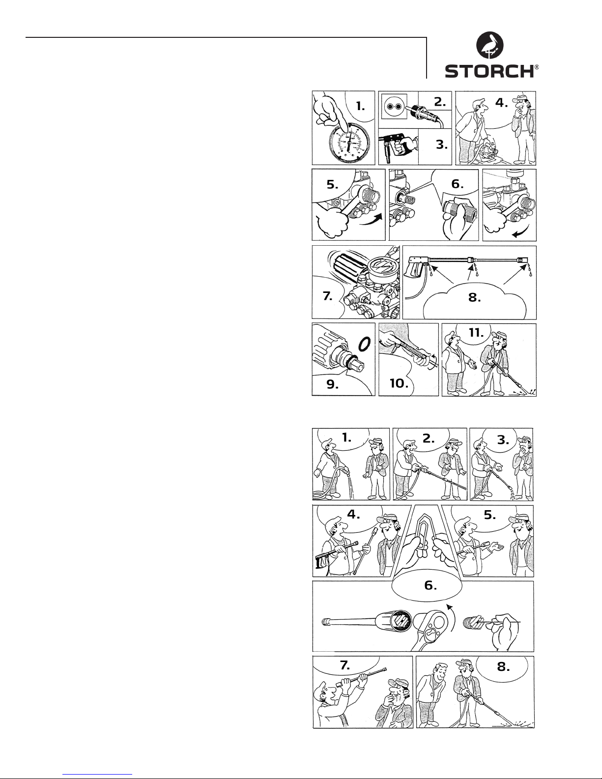
67
Odstraňte únik vody u hadice nebo pistole
Po uzavření pistole ukazuje manometr plný tlak!
Regulátor tlaku stále zapíná a vypíná!
1. Když tlakoměr ukazuje plný tlak
2. Vytáhněte síťovou zástrčku ze zásuvky!
3. Pistoli stiskněte tak, aby se snížil tlak
4. Nejdříve odmontujte hadici
5. Potom odšroubujte vidlicovým klíčem ústí čerpadla
6. Vyčistěte těleso se zpětným rázem nebo vyměňte
O-kroužek
7. Kvůli ztrátě tlaku stále zapíná a vypíná regulátor tla-
ku
8. Na těchto třech místech může vytékat voda. Zkon-
trolujte těsnění a pokud je třeba vyměňte O-kroužky
nebo nechte pistoli zkontrolovat výrobcem
9. Vždy vyměňte O-kroužek u trysky nebo u vysokotlaké
hadice
10. Hadici, pistoli a trysku opět sešroubujte dohromady
11. Tak rychle je porucha odstraněna
Ucpaná tryska
Z trysky nevytéká žádná voda, ale tlakoměr ukazuje plný
tlak!
1. Nejdříve vypláchněte hadici od zbytků
2. Obvykle nyní vytéká silný proud vody
3. Pokud z trysky jenom kape voda
4. odmontujte trysku a vyčistěte ji
5. U ploché trysky je pouze třeba vyčistit přední trysku
6. Vsuňte špičatý předmět do otvoru a krytku táhněte
dozadu - připravte si nyní kancelářskou sponku a
vyčistěte trysku
7. Zkontrolujte pohledem, zda je tryska vyčištěná
8. Nyní to funguje stejně dobře jako dřív
Page 68
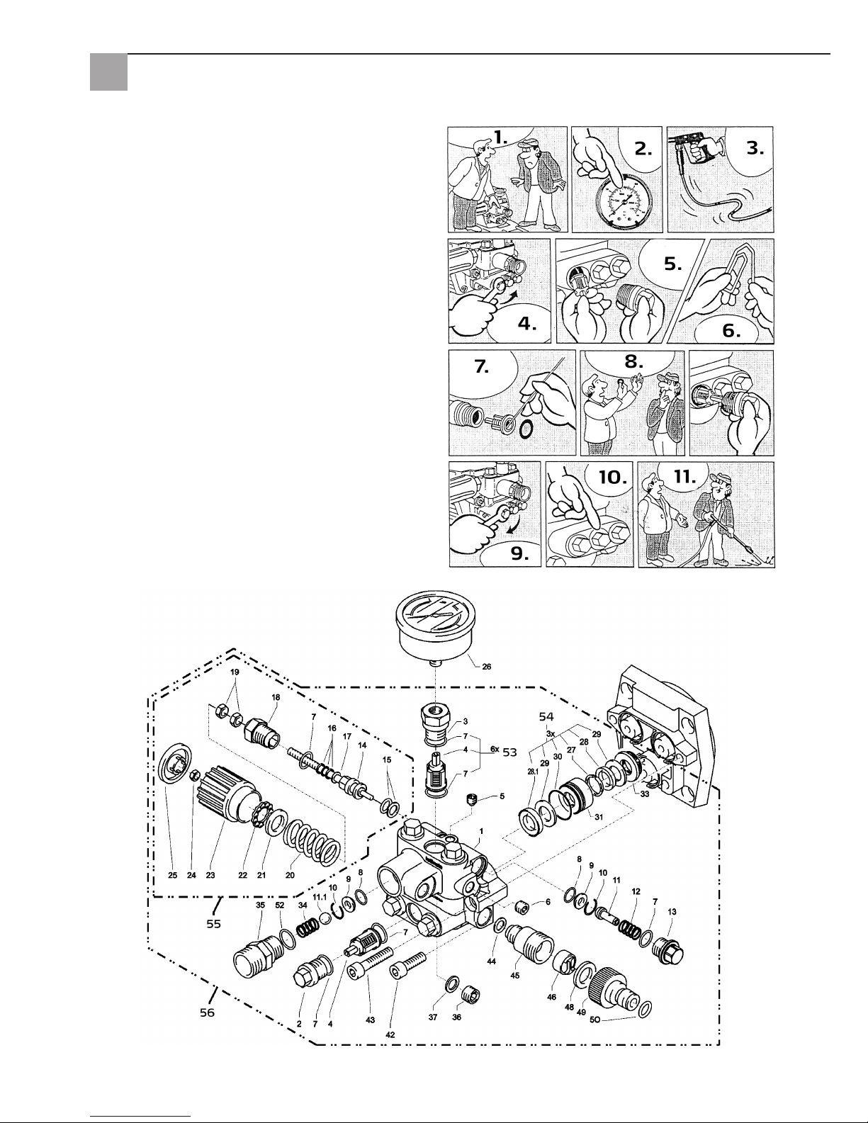
68
Ventil je znečištěný nebo slepený
• Tlakoměr neukazuje plný tlak
• vysokotlaká hadice vibruje
• Voda nárazově vytéká
• Ventily se mohou slepit, pokud přístroj nebyl dlouho
používán
1. pokud je ventil ucpaný
2. ukazuje manometr malý nebo vůbec žádný tlak
3. nebo vysokotlaká hadice vibruje
4. Odšroubujte očkovým klíčem ventil
5. a vyjměte šroub ventilu, ventil a pryžový kroužek
6. připravte si kancelářskou sponku...
7. a odstraňte nečistoty z ventilu
• ventil musí být uvnitř zavřený
8. Na těchto místech může vytékat voda. Pryžové
těsnění vzadu opět pevně přitiskněte
9. šroub ventilu opět pevně dotáhněte
10. ... a opakujte postup u všech 6 ventilů
11. Tak rychle je porucha odstraněna
Pouzdro ventilu
Page 69
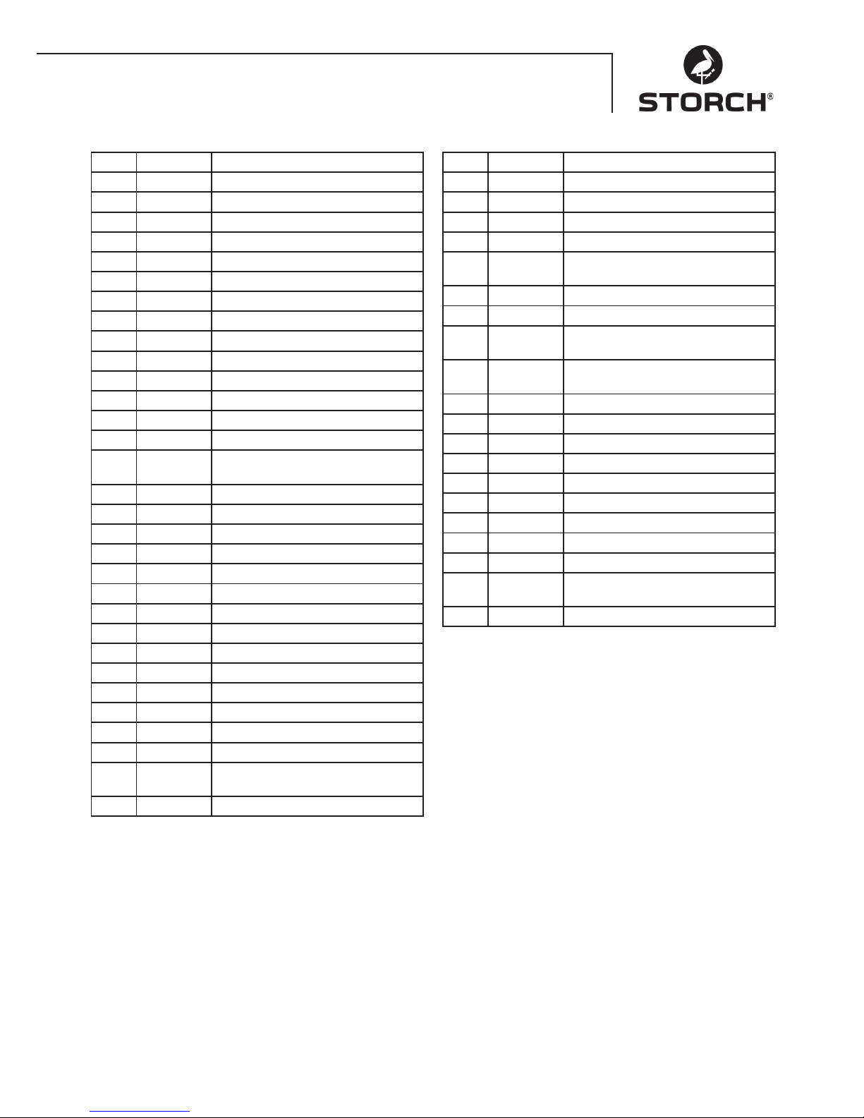
69
Pouzdro ventilu
Pol. Obj.č. Název
1 65 62 69 Pouzdro ventilu
2 65 62 71 Ventilová zátka
3 65 62 72 Ventilová zátka s R1/4"IG
4 65 63 26 Ventil
5 65 62 74 Těsnící zátka M 8 x 1
6 65 62 76 Těsnící zátka M 10 x 1
7 65 62 66 O-kroužek 12 x 2
8 65 62 77 O-kroužek 11 x 1,5
9 65 62 78 Sedlo z ušlechtilé oceli
10 65 62 79 Pojistný kroužek
11 65 62 81 Odpouštěcí ventil u náběhu
11.1 65 62 82 Kulička z ušlechtilé oceli 10,0 mm
12 65 62 83 Pružina z ušlechtilé oceli
13 65 62 84 Uzavírací šroub
14 65 62 86 Řídící píst 6 mm pro AZ s
těsněním
15 65 62 87 Parbaks pro píst 14 mm
16 65 62 88 Parbaks pro vřeteno 6 mm
17 65 62 89 Podložka MS
18 65 62 91 Vedení pístu 6 mm
19 65 62 92 Matice M6
20 65 62 93 Pružina černá pro čerpadlo AZ
21 65 62 94 Pružinová podložka
22 65 62 96 Kuličkové ložisko
23 65 62 97 Ruční kolo M6 pro čerpadlo AZ
24 65 62 98 Matice M6 s SW8
25 65 62 99 Krytka pro ruční kolo čerpadlo AZ
26 65 63 01 Tlakoměr
27 65 63 02 Opěrný kroužek
28 65 63 03 Manžeta 14 x 24 x 5/2,5
28.1 65 63 04 Manžeta tkanina
14 x 24 x 5/2,5
29 65 63 06 Zpětný kroužek 14 x 24
Pol. Obj.č. Název
30 65 63 07 O-kroužek 24 x 2
31 65 63 08 Kroužek proti úniku netěsností
32 65 63 09 Mezikroužek s podpěrou
33 65 63 11 Pružina proti zpětnému rázu
34 65 63 12 Výstupní díl pro
kulový zpětný ventil
35 65 63 13 Uzavírací ucpávka
36 65 62 37 Hliníkový těsnící kroužek
42 65 62 63 Vnitřní šestihranný šroub
M8 x 25 - A2
43 65 63 14 Vnitřní šestihranný šroub
M8 x 45 - A2
44 65 63 16 Měděný těsnící kroužek
45 65 63 17 Sací připojení
46 65 61 16 Vodní filtr
48 65 61 17 Pryžový těsnicí kroužek
49 65 61 18 Zasouvací spoj
50 65 63 18 O-kroužek
52 65 63 19 O-kroužek 18 x 2
53 65 63 27 Sada na opravy ventilů
54 65 63 22 Sada na opravy manžet
55 65 63 23 Řídicí píst kompletní s ručním
kolem
56 65 63 28 Pouzdro ventilu kompletní
Page 70
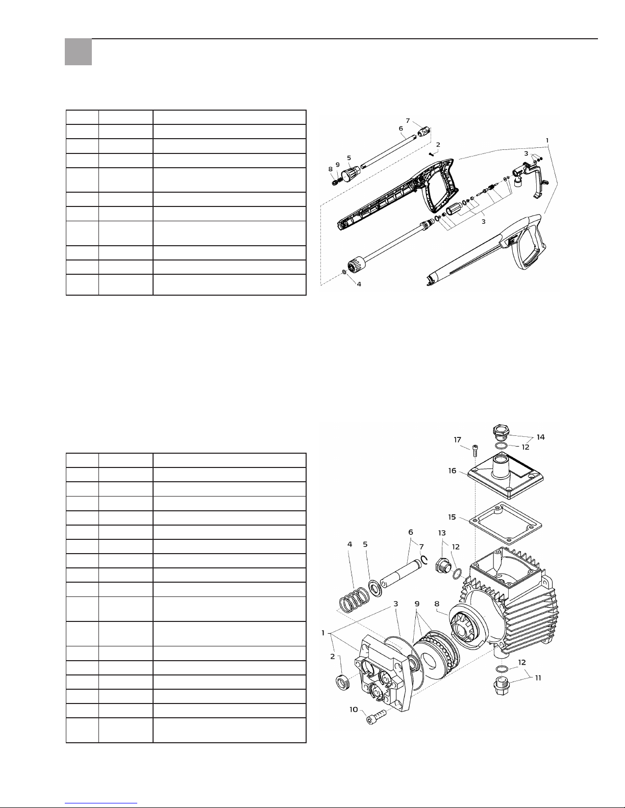
70
Pistole s tryskou
Převodový díl
Pol. Obj.č. Název
1 65 62 52 Krycí deska
2 65 62 53 Olejové těsnění 14 x 24 x 7
3 65 62 54 O-kroužek 83 x 2
4 65 62 56 Plunžrová pružina
5 65 62 57 Pružinová podložka 14 mm
6 65 62 58 Plunžr 14 mm AZ-L
7 65 62 59 Rozpěrný kroužek 14 mm
8 65 63 31 Chvějivý kotouč 9,5°
9 65 62 62 Axiální kuličkové ložisko 3-dílné
10 65 62 63 Šroub s vnitřním šestihranem
M8 x 25
11 65 62 64 Zátka k vypouštění oleje M18 x 1,5
s magnetem
12 65 62 66 O-kroužek 12 x 2
13 65 64 33 Olejové průzorové sklo
14 65 64 32 Šroub u uzávěru oleje červený
15 65 62 67 Těsnění olejové víko
16 65 62 68 Víko olejový kryt
17 65 60 98 Šroub s vnitřním šestihranem
M5 x 12
Pol. Obj.č. Název
1 65 62 28 Kryt pistole vpravo + vlevo
2 65 62 29 Šroub 3,5 x 14
3 65 62 31 Sada na opravy rukojeť pistole
4 65 65 59 O-kroužek ST30 pro vysokotlakou
hadici a trysku
5 65 62 32 Ochrana trysky M12 x 1
6 65 62 33 Trubka 500 mm
7 65 62 34 ST30 šroubení M22 x 1,5/R1/4" s
ISK
8 65 63 29 Plochá tryska
9 65 62 37 Hliníkový těsnící kroužek
bez
obr.
65 65 33 Rukojeť vysokotlaké pistole
Page 71
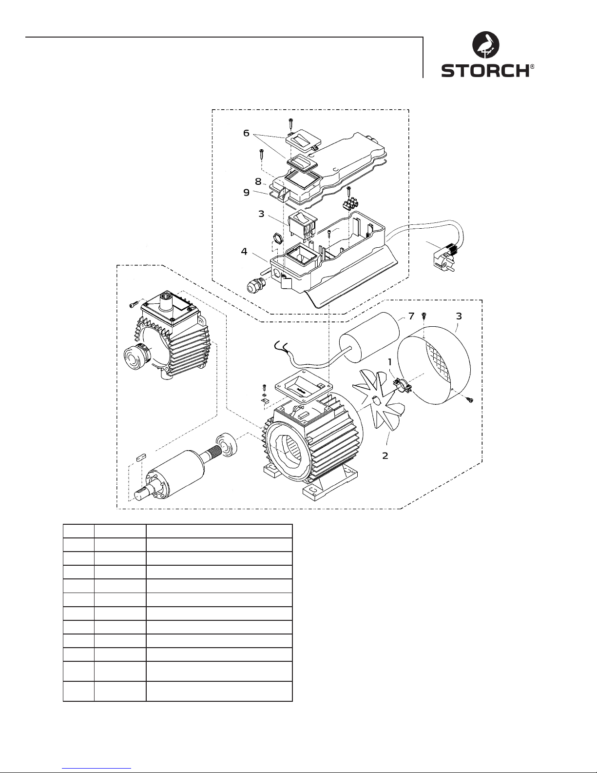
71
Motor
Pol. Obj.č. Název
1 65 62 38 Spona pro lopatkové kolo
2 65 62 39 Lopatkové kolo
3 65 62 41 Víko větráku
4 65 62 42 Spínací skříň - dolní díl
5 65 63 32 Spínač/vypínač 12 A
6 65 62 44 Kryt spínače včetně těsnění
7 65 65 64 Kondenzátor 40 mycroF
8 65 62 47 Kryt u spínací skříně
9 65 62 48 Těsnění u krytu
bez
obr.
65 63 33 Motor kompletní
bez
obr.
65 63 34 Spínací skříň kompletní
Page 72

72
Záruka
Záruční podmínky
U našich přístrojů platí zákonné záruční lhůty 12 měsíců od data zakoupení/data faktury obchodního konečného zákazníka. Pokud jsou delší lhůty v cestě námi vypsanému prohlášení o záruce, jsou zvláště vyznačeny v návodu k obsluze
příslušných přístrojů.
Uplatňování
V případě záručního příp. garančního případu žádáme, aby bylo zasláno kompletní zařízení dohromady s fakturou do
našeho střediska Logisitk Center v Berka nebo do námi autorizované servisní stanice.
Kontaktujte prosím nejdříve hotline servis firmy STORCH: +49 800. 7 86 72 47
Nárok na záruku příp. garanci
Nároky na záruku existují výhradně u materiálu nebo výrobní vady a také výhradně při používání přístroje v souladu s
určeným účelem. Díly podléhající opotřebení jako např. převodovka, těsnění, písty, ventily, ložiska nespadají do takovýchto nároků na záruku. Veškeré nároky zanikají zamontováním dílů cizího původu, při nepřiměřeném zacházení a
skladování a také při zřejmém nedodržování provozního návodu.
Provádění oprav
Veškeré opravy smějí být prováděny výhradně naším závodem nebo servisními stanicemi autorizovanými firmou
STORCH.
Zkoušky
Stroj je třeba dle „Směrnic pro kapalinové trysky“ v případě potřeby, avšak minimálně každých 12 měsíců, zkontrolovat
odborníkem ohledně toho, zda je dále zaručen bezpečný provoz. Výsledky zkoušky je třeba písemně zaznamenat. Stačí
neformální záznamy.
Ochrana před úrazem
Stroj je vybaven tak, že při vhodné obsluze jsou úrazy vyloučeny. Obsluhující osobu je třeba upozornit na nebezpečí
úrazu od horkých částí stroje a vysokotlakého proudu kapaliny. Je třeba dodržovat „Směrnice pro kapalinové trysky“.
Výměna oleje
Před každým uvedením do provozu zkontrolujte stav oleje u průzorového skla. (Dodržujte vodorovnou polohu!) Hladina
oleje by měla být u středu průzorového skla. Při vysoké vlhkosti vzduchu a výkyvech teploty je možná tvorba kondenzované vody, potom musí být vyměněn olej (šedá barva).
První výměna oleje po cca 50 provozních hodinách. Potom není třeba výměna oleje pro životnost přístroje. Pokud by
bylo třeba vyměnit olej, při opravě nebo protože má olej šedou barvu, tak je třeba otevřít nad nádrží šroub k vypouštění
oleje a přístroj vyprázdnit. Olej je nutno zachytit do nádrže a následně zlikvidovat podle předpisů. Nový olej: 0,25 l motorový olej W 15/40.
Únik oleje
Při úniku oleje okamžitě vyhledejte nejbližší zákaznickou službu (obchodníka). (Škody v oblasti životního prostředí,
poškození převodovky)
Page 73
73
Prohlášení o shodě ES
Název / adresa výstavce: STORCH Malerwerkzeuge & Profigeräte GmbH
Platz der Republik 6-8
D - 42107 Wuppertal
Tímto prohlašujeme, že dále uvedený stroj
Označení stroje: Vysokotlaké čistící zařízení 120 barů Compact
Typ stroje: Vysokotlaké čistící zařízení
odpovídá příslušným ustanovením následujících směrnic:
Směrnice o strojích: 2006 / 42 / EG
Směrnice o nízkém napětí: 2006 / 95 / EG
Směrnice ES
Elektromagnetická slučitelnost: 2004 / 108 / EG
Směrnice o hluku: 2005 / 88 EG, čl. 13
Stroje pro tryskání vysokotlakou vodou
Dodatek 3, díl B, oddíl 27
Zplnomocněnec k sestavení technických podkladů:
STORCH Malerwerkzeuge & Profigeräte GmbH
Platz der Republik 6-8
D-42107 Wuppertal
Jörg Heinemann
- Jednatel -
Wuppertal, 06 - 2013
Page 74

74
Page 75

75
Page 76
76
Malerwerkzeuge & Profigeräte GmbH
Platz der Republik 6 - 8
D-42107 Wuppertal
Telefon: +49 (0)2 02 . 49 20 - 0
Telefax: +49 (0)2 02 . 49 20 - 111
E-mail: [email protected]
Internet: www.storch.de
H 002698
06-2013
Art.-Nr. Bezeichnung
65 60 05 Hochdruckreiniger 120 Compact
Art. nr. Beschrijving
65 60 05 Hogedrukreiniger 120 Compact
Référence Désignation
65 60 05 Nettoyeur haute pression 120 Compact
N. art. Denominazione
65 60 05 Idropulitrice ad alta pressione
120 Compact
Art. no. Description
65 60 05 High pressure cleaner 120 Compact
Výr. č. Označení
65 60 05 Vysokotlaké čistící zařízení
120 Compact
 Loading...