

Page 1
InfoStation II Ultra160 I/O Kits
InfoStation II Ultra160 I/O Kits
CAUTION: Remove ALL power from the InfoStation II before removing the I/O module.
The I/O module contains NO USER SERVICEABLE PARTS inside the unit.
Refer ALL servicing to qualified service personnel!
NOTES: The I/O module is NOT hot-swappable! Remove ALL power to chassis
before removing and installing the I/O module.
Refer to both the InfoStation II Users Guide and InfoStation II Installation
Guide for further information.
A #2 Phillips screwdriver will be required for this procedure.
The InfoStation IIs scalable backplane design allows additional I/O module and terminator kits
to be offered, supporting a variety of Ultra160 drive-to-channel configurations. Additional
I/O module kits (P/N S10A117) and I/O repeater module kits (P/N DXIFS-RPTR160-KIT) are
available to upgrade the single and dual-channel InfoStation II models to support a total of four
(4) Ultra160 channels.
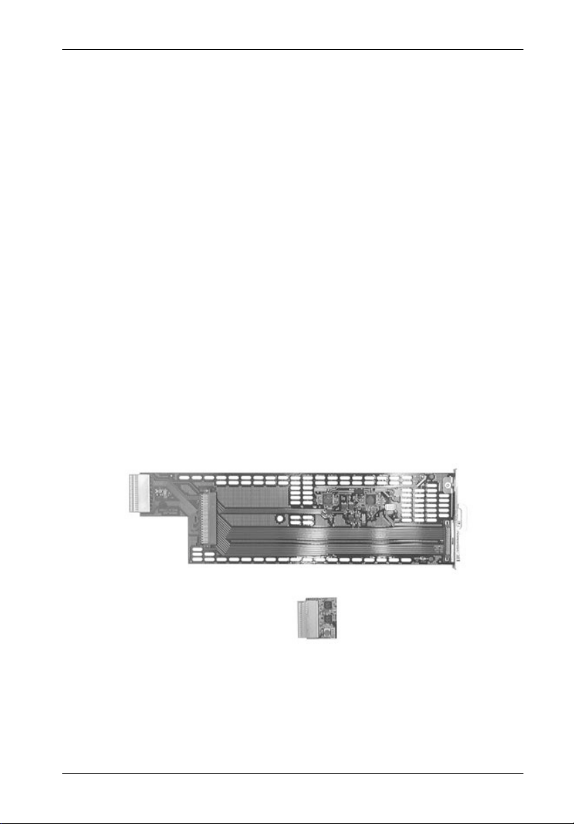
Each I/O kit comes with an I/O module and terminator.
Ultra160 I/O Module
IFS14_34
Terminator
Figure 1: I/O Module Kit
D89-0000-0176 Rev. A00 StorCase Technology, Inc.
Page 2
InfoStation II Ultra160 I/O Kits
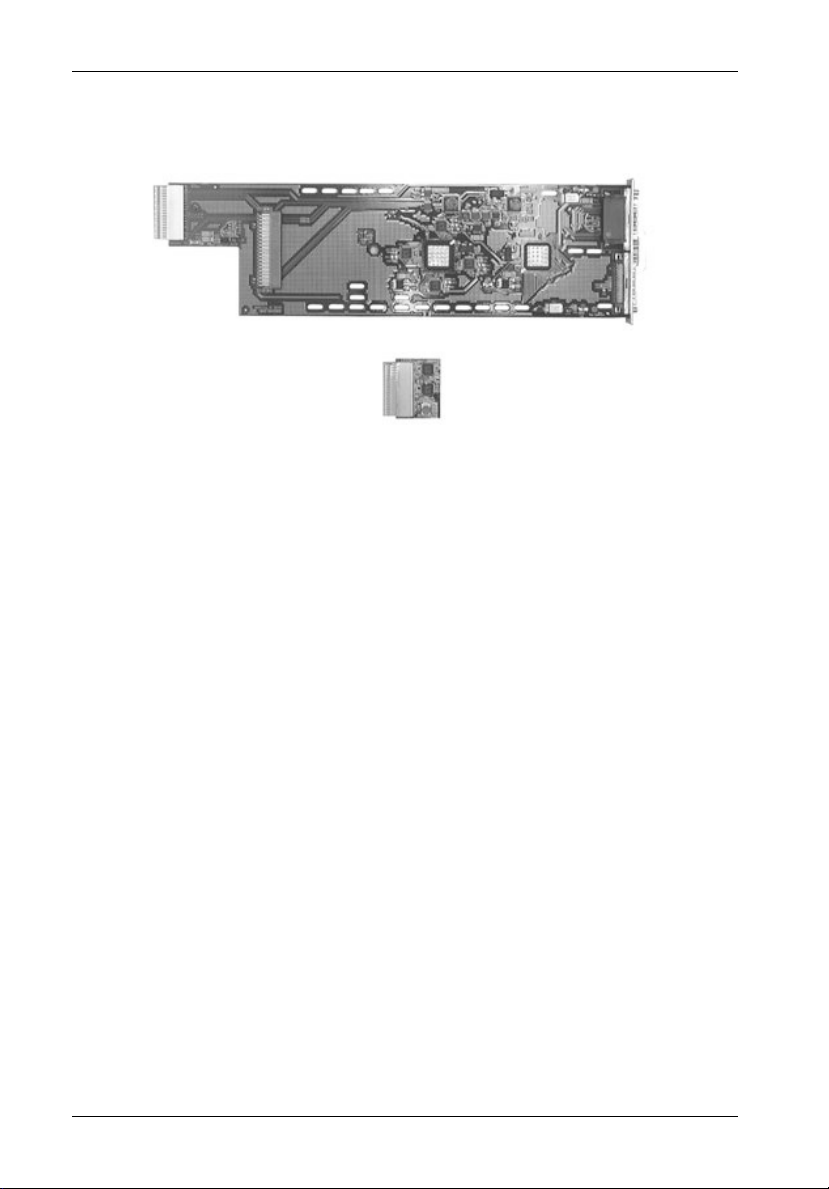
Ultra160 I/O Repeater Module
Terminator
Figure 2: I/O Repeater Module Kit
IFS14_35
StorCase Technology, Inc. D89-0000-0176 Rev.A00
Page 3
InfoStation II Ultra160 I/O Kits
Removing and Installing the I/O Module
(Procedure and information below applies to both the I/O Module and the optional I/O Repeater
Module)
CAUTION: Remove ALL power from the InfoStation II before removing the I/O module.
The I/O module contains NO USER SERVICEABLE PARTS inside the unit.
Refer ALL servicing to qualified service personnel!
NOTES: The I/O module is NOT hot-swappable! Remove ALL power to chassis
before removing and installing the I/O module.
A #2 Phillips screwdriver will be required for this procedure.
1. Unplug the InfoStation II and verify that ALL cables have been disconnected.
2. Place the InfoStation II on a soft clean surface to protect finish of the chassis.
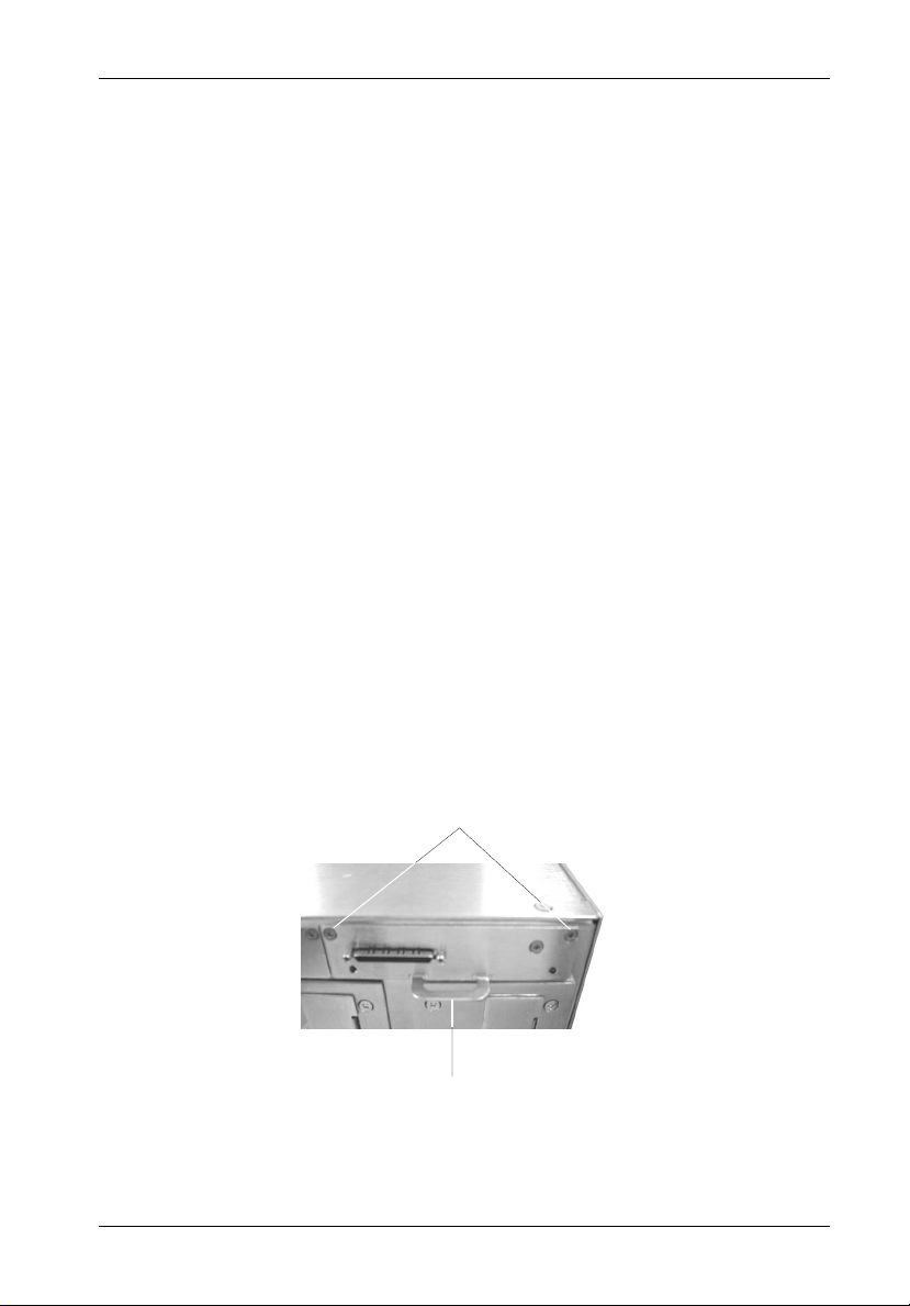
3. Loosen and remove the two (2) #6-32 Phillips Flat Hd. screws securing the I/O
module to the InfoStation II chassis (Figure 3).
4. Remove the I/O module by grasping handle and pulling out from chassis.
5. To reinstall I/O module, simply reverse above mentioned steps.
NOTE: Blank plate (provided) must be installed if module slot is left empty. Instal-
lation of the blank plate is necessary for proper cooling inside chassis.
#6-32 Phillips
Flat Hd. Screw
(2 Total)
IFS14_10
Module
Handle
Figure 3: Removing and Installing the I/O Module
D89-0000-0176 Rev. A00 StorCase Technology, Inc.
Page 4

Removing the InfoStation II Access Panel
InfoStation II Ultra160 I/O Kits
CAUTION: Remove ALL power from the InfoStation II before removing the access
panel(s). The InfoStation II contains NO USER SERVICEABLE PARTS
inside the unit. Warranty is VOID if any of the modules inside the
InfoStation II are opened. Refer ALL servicing to qualified service
personnel!
NOTE: A #2 Phillips screwdriver will be required for this procedure.
1. Unplug the InfoStation II and verify that ALL cables have been disconnected.
2. Place the InfoStation II on a soft clean surface to protect finish of the chassis.
3. Remove the ten (10) #6-32 Phillips Flat Head screws securing the access panel to
the InfoStation II chassis (Figure 4).
NOTE: Remove the access panel located on the RIGHT SIDE (Top) of the chassis
only.
4. Remove the access panel by carefully lifting the panel(s) off the chassis (Figure 8).
5. To reinstall panel, simply reverse the above mentioned steps.
#6-32 Phillips
Head Screw
(10 total)
Access Panel
(Right Side)
InfoStation II
Chassis
IFS14_19
Figure 4: Removing the Access Panel
StorCase Technology, Inc. D89-0000-0176 Rev.A00
Page 5

InfoStation II Ultra160 I/O Kits
Figure 5 below shows the inside of the InfoStation II chassis (single-channel configuration)
with the access panel removed.
I/O
Module
Jumper
Block
Jumper
Block
Jumper
Block
Terminator
Block
IFS14_20
Figure 5: Single-Channel Backplane Configuration
D89-0000-0176 Rev. A00 StorCase Technology, Inc.
Page 6

Configuring the InfoStation II for Dual-Channel
InfoStation II Ultra160 I/O Kits
CAUTION: Remove ALL power from the InfoStation II before removing the I/O module.
The I/O module contains NO USER SERVICEABLE PARTS inside the unit.
Refer ALL servicing to qualified service personnel!
NOTE: A #2 Phillips screwdriver will be required for this procedure.
1. Unplug the InfoStation II and verify that all cables have been disconnected.
2. Place the InfoStation II on a soft clean surface to protect finish of the chassis.
3. Loosen and remove the two (2) #6-32 Phillips Flat Hd. screws securing the I/O
blank plate (refer to Figure 7 for correct location) to the InfoStation II chassis (Figure
6).
4. Remove the I/O blank plate.
5. Remove access panel (Figure 4).
6. Remove the center jumper block so that the second I/O repeater module and terminator can be installed. Correct dual-channel backplane configuration is shown
in Figure 8.
#6-32 Phillips
Flat Hd. Screw
(2 Total)
I/O Blank
Plate
IFS14_11
Figure 6: Removing the I/O Blank Plate
StorCase Technology, Inc. D89-0000-0176 Rev.A00
Page 7

InfoStation II Ultra160 I/O Kits
Module #2
(Channel 2)
Module #1
(Channel 1)
InfoStation II Rear
Figure 7: Dual-Channel Rear Panel Configuration
I/O
Module
Jumper
Block
Terminator
Block
I/O
Module
IFS14_33
Jumper
Block
Terminator
Block
IFS14_21
Figure 8: Dual-Channel Backplane Configuration
D89-0000-0176 Rev. A00 StorCase Technology, Inc.
Page 8

Configuring the InfoStation II for 4-Channel
InfoStation II Ultra160 I/O Kits
CAUTION: Remove ALL power from the InfoStation II before removing the I/O module.
The I/O module contains NO USER SERVICEABLE PARTS inside the unit.
Refer ALL servicing to qualified service personnel!
NOTE: A #2 Phillips screwdriver will be required for this procedure.
1. Unplug the InfoStation II and verify that ALL cables have been disconnected.
2. Place the InfoStation II on a soft clean surface to protect finish of the chassis.
3. Loosen and remove the two (2) #6-32 Phillips Pan Head screws securing each I/O blank
plate to the InfoStation II chassis (Figure 6).
4. Remove all three (3) I/O blank plates.
5. Remove access panel (Figure 4).
6. Remove all the jumper blocks so that I/O modules ( #2, 3, and 4) and terminators (#2,
3, and 4) can be installed. Correct 4-channel backplane configuration is shown in
Figure 9.
I/O
Module
Terminator
Block
I/O
Module
Terminator
Block
I/O
Module
Terminator
Block
I/O
Module
Terminator
Block
IFS14_22
Figure 9: 4-Channel Backplane Configuration
StorCase Technology, Inc. D89-0000-0176 Rev.A00
 Loading...