

Page 1

StorCase® Technology
Rhino®JR
RJR100
Removable Drive Enclosure
User's Guide
Part No. D89-0000-0093 D02 December 2002
StorCase Technology, Inc.
17600 Newhope Street
Fountain Valley, CA 92708-9885
Phone (714) 438-1850
Fax (714) 438-1847
Page 2
STORCASE® TECHNOLOGY
RHINOJR
RJR100
The StorCase Technology RhinoJR (P/Ns RJR100-A100 and RJR100-SWU2X) removable
drive carrier and receiving frame provides low cost, durable and reliable mounting for 3.5
AT/IDE and Ultra ATA/100 or SCSI drives within 5.25 half-height peripheral slots. The
RhinoJR is constructed of lightweight, durable cast nickel and allows a drive to be removed
and transported to another RhinoJR-equipped computer or expansion chassis, and also
provides the ability to secure sensitive data by removing and storing the drive safely for
future use.
The RhinoJR carrier is also available separately. Contact your StorCase dealer for further
details and ordering information.
INTRODUCTION
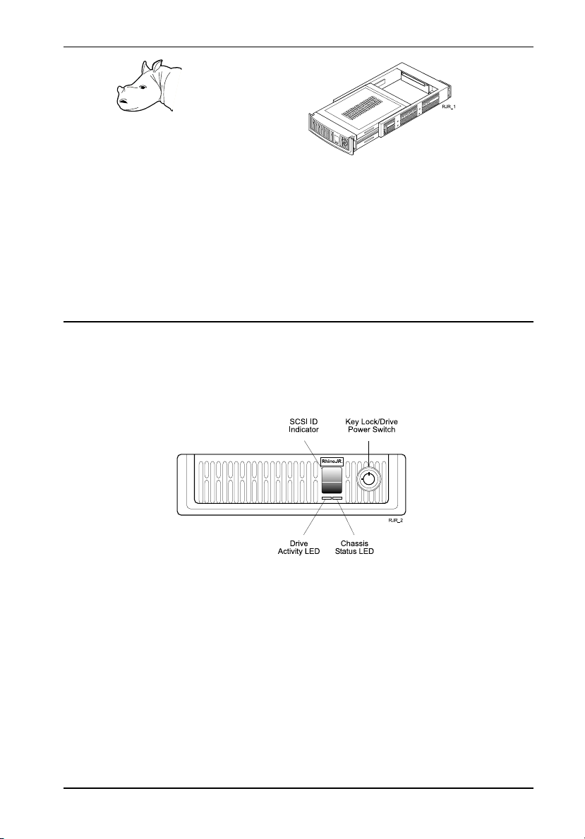
Drive Carrier
1
Key Lock/Drive Power Switch - Performs three functions. The key lock assures proper
seating of the drive carrier within the receiving frame, turns power to the drive carrier on and
off, and prevents unauthorized removal or installation of the carrier. For the computer to
access data on the RhinoJR drive, the key must be turned counterclockwise to the locked
position.
SCSI ID Indicator (Does not apply to the RJR100-A100 model) - Displays the physical SCSI
address of the RhinoJR carrier, but only when the carrier is Installed and Locked in the
receiving frame. The SCSI ID is selected by means of the SCSI ID select switch located
behind the drive carrier.
Drive Activity LED - Provides a visual indication of drive activity.
RJR100 Users Guide- Rev. D02
StorCase Technology, Inc.
Page 3
2
Chassis Status LED - Provides the following information:
Green = Power ON (and both fans working properly)
Red = Fan Failure (If either carrier or receiving fan fails)
NOTE: An audible alarm will also sound if either of the fans fail.
Front Cooling Fan (Not Shown) - Fan helps provide ample carrier ventilation (located inside
the front of the drive carrier).
NOTE: Front fan may be manually disabled for special applications. Refer to Front Fan
Alarm Disable SW2 (or S2...) for further information.
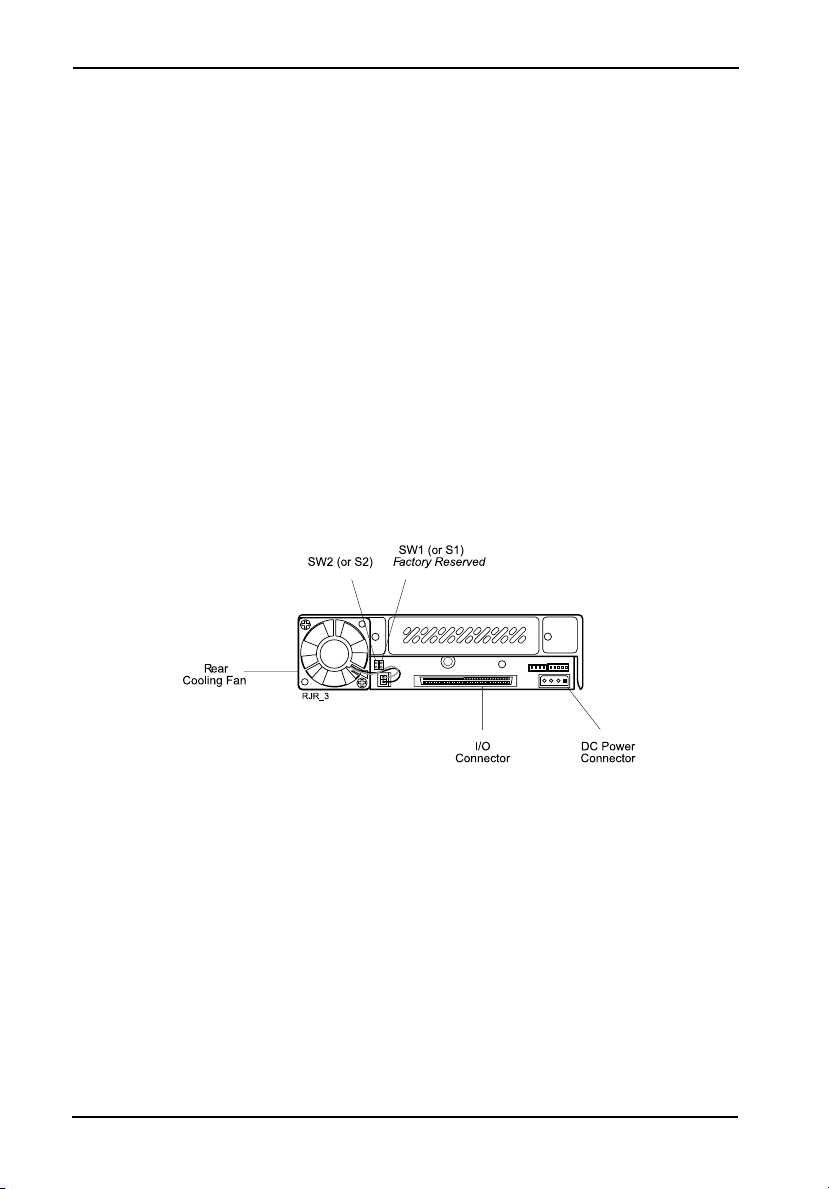
Receiving Frame Rear Panel
Rear Cooling Fan - Fan helps provide ample carrier ventilation.
I/O Connector - The input/output connector provides a standard interface for AT/IDE or
SCSI signals, depending on model.
DC Power Connector - The RhinoJR uses a standard 4-pin power connector to accept DC
power.
SW1 (or S1, depending on model) - Factory-reserved jumper option - Do Not Use!
StorCase Technology, Inc.
RJR100 Users Guide - Rev. D02
Page 4

Front Fan Alarm Disable SW2 (or S2, depending on model) - This jumper option allows the
front fan alarm to be disabled when the front fan is manually disabled (see figure on page 2).
Jumper is included in the RhinoJR accessory packet.
Although not recommended, the front fan may be manually disabled by disconnecting the
front fan power cable (red/black cable) from the drive carrier board, located inside the
carrier (see figure below).
NOTE: For high performance drives (10K RPM or higher), BOTH fans should be left enabled!
3
No jumper (Factory Default)- Audible alarm will sound and LED will turn red when
Jumper on SW2 (or S2) - Jumper installed on SW2 will disable front fan audi-
either fan fails.
ble alarm and LED when the front fan has been manually disabled. Rear fan audible alarm and LED will still
function in the case of rear fan failure.
RJR100 Users Guide- Rev. D02
StorCase Technology, Inc.
Page 5

4
INSTALLATION
NOTES: For SCSI Ultra2 (LVD) operation, the RJR100-SWU2X requires LVD chassis and
cabling. The RJR100-SWU2X supports LVD implementations with a maximum of 15
drives in one chassis.
For Ultra ATA/100 (100MByte/sec) operation, an Ultra ATA/100 controller and hard
drive(s), and appropriate 40-pin, 80-conductor cable are required.
Installing the Drive into the Carrier
While performing the steps in this section, work on a soft surface to prevent excessive
shock to the drive being installed. Also refer to the manufacturers documentation provided
with the drive. A Phillips #1 and #2, and flat head screwdriver will be required for installation.
1. Remove both top and bottom covers from the drive carrier as shown. If
NOTE: Both covers need to be removed in order to install the drive into the RhinoJR car-
rier.
needed, gently pry off covers with a flat head screwdriver.
StorCase Technology, Inc.
RJR100 Users Guide - Rev. D02
Page 6

2. Attach the I/O cable from the RhinoJR carrier to the disk drive.
3. Attach the DC power cable to the disk drive.
5
4. Attach the 5-pin ID select cable to the disk drive (Does not apply to the
5. Carefully insert the drive into the carrier. Make sure none of the cables are pinched.
Side-mount the drive into the carrier with the four (4) #6-32 small Phillips Pan Head screws
provided.
6. Reinstall the top and bottom covers on to the drive carrier.
RJR100-A100 model).
RJR100 Users Guide- Rev. D02
StorCase Technology, Inc.
Page 7

6
Installing the Receiving Frame
The drive should be installed into the carrier before installing the receiving frame into the
mounting bay of a computer or expansion chassis.
1. Turn OFF power to computer or expansion chassis.
2. Open computer or expansion chassis according to manufacturers in-
3. With the drive carrier locked into place inside the receiving frame, install
4. Adjust the front of the receiving frame so that the carrier slides freely in
5. Connect the I/O cable from the host adapter to the receiving frame.
6. Connect the DC power cable from the DC power supply in the computer
structions. If necessary, temporarily remove any expansion boards that
may make installation difficult.
the RhinoJR into the 5.25 drive opening in the computer or expansion
chassis. Fasten into place with the four (4) #6-32 large Phillips Pan Head
screws provided. Figure below illustrates the location of the mounting
holes.
and out of the receiving frame guides. The position of adjoining peripheral units may require adjustment.
or expansion chassis to the power connector on the RhinoJR receiving
frame rear panel.
7. Replace any expansion boards that may have been removed earlier.
Replace the system cover according to the manufacturers instructions.
8. Reconnect any system or peripheral cables removed earlier.
9. Turn on power to the computer. If the installation was successful, and
all cables have been properly attached, the system should boot normally.
Although the computer may not recognize the RhinoJR yet, the Chassis
Status LED indicator on the RhinoJR front panel should illuminate.
StorCase Technology, Inc.
RJR100 Users Guide - Rev. D02
Page 8

Selecting the SCSI ID Number
NOTE: There is no SCSI ID select switch on the RJR100-A100 model.
The RhinoJR SCSI ID selection switch is located on the rear of the carrier, as shown in the
figure below. Carefully select the appropriate SCSI ID number for the installed device.
Selecting an invalid ID number, or selecting the same number on different devices may cause
unpredictable results and the computer system may not recognize the installed device.
7
1. Verify that power is turned on to the RhinoJR receiving frame by turning
2. Unlock the carrier and remove it from the receiving frame.
WARNING: Unlocking the carrier unit turns DC power off to the drive. Since disk
3. After selecting an appropriate SCSI ID number, replace the RhinoJR
on the computer or external chassis. A number should appear in the
SCSI ID indicator window if the carrier is locked in place.
drives require a short amount of time to spin down, allow about 15 seconds before pulling the carrier unit out of the receiving frame to avoid
possible damage to the drive.
carrier in the receiving frame, and LOCK IT IN PLACE.
RJR100 Users Guide- Rev. D02
StorCase Technology, Inc.
Page 9

8
SPECIFICATIONS
SCSI RhinoJR subsystems conform to the Small Computer Systems Interface (SCSI) Standard set by the American National Standards Institute (ANSI).
Description
(1)
RJR100 Frame and Carrier
RJR100 Carrier Only
(1)
Available for AT/IDE (RJR100-A), Ultra ATA/100
(RJR100-A100), and SCSI Wide Ultra2 (RJR100SWU2X) drives.
Weight
2.0lb (0.91kg)
1.4lb (0.64kg)
Physical Specifications
Height
Width
Depth
Environmental Specifications
Operating
Ambient Temperature 5° C to 50° C -20° C to 60° C
Relative Humidity
Altitude
(2)
Shock
(1)
Non-condensing with maximum gradient of 10% per hour.
(2)
11 msec pulse width 1/2 sine wave.
(1)
10% to 80% 10% to 90%
-1000 to 50,000 ft -1000 to 50,000 ft
-304m to 15240m -304m to15240m
10g 60g
Storage
Chassis Reliability/Maintainability
MTBF 20,000 Hours
Preventive
Maintenance
None
Certification
EMI Standards
EMC Standards
FCC Part 15 Class B, CE CISPR22 Class B, C-Tick
EN55022, IEC1000-4-2, IEC1000-4-3, IEC1000-4-4
1.68 (42.7mm)
5.75 (146.0mm)
8.68 (220.5mm)
Fan Air Flow
Total for 2 Fans 9.6 CFM
RJR_specsb
These specifications are for reference only.
StorCase Technology, Inc.
RJR100 Users Guide - Rev. D02
Page 10

LIMITED WARRANTY
STORCASE TECHNOLOGY, Incorporated (StorCase) warrants that its products will be free
from defects in material and workmanship, subject to the conditions and limitations set forth
below. StorCase will, at its option, either repair or replace any part of its product that proves
defective by reason of improper workmanship or materials. Repair parts or replacement
products will be provided by StorCase on an exchange basis, and will be either new or
reconditioned to be functionally equivalent to new.
This warranty does not cover any product damage that results from accident, abuse, misuse,
natural or personal disaster, external power surge or failure, or any unauthorized disassembly, repair or modification. StorCase will not be responsible for any software, firmware or other
customer data stored within, or interfacing with a StorCase product.
Duration of Warranty
Seven-Year Warranty: The following StorCase products are covered by this warranty for
a period of seven (7) years from the original date of purchase from StorCase or its authorized
reseller: all Data Express® removable device enclosures and all StorCase interface cables and
accessories specifically intended for use with these products. Data Silo®, Data Stacker® and
InfoStation® products are covered by this warranty for a period of seven (7) years, excepting
the RAID controller, power supply, fan and blower components, which are covered by the
three-year warranty described below.
Three-Year Warranty: The following StorCase products are covered by this warranty for
a period of three (3) years from the original date of purchase from StorCase or its authorized
reseller: all Rhino®JR external expansion chassis and all RAID controller modules. In addition,
the following components of the Data Silo®, Data Stacker®, InfoStation® products are subject
to warranty for a period of three (3) years: all power supplies, fans and blowers.
9
Warranty Claim Requirements
To obtain warranty service, the defective product must be returned to your local authorized
StorCase dealer or distributor, or, with prior StorCase approval, to the StorCase factory
service center.
For defective products returned directly to StorCase, a Return Material Authorization (RMA)
number must be obtained by calling StorCase Customer Service at (714) 445-3455. The RMA
number must be prominently displayed on the outside of the return package. Shipments must
be freight-prepaid and insured, and must include the product serial number, a detailed
description of the problem experienced, and proof of the original retail purchase date. Products
must be properly packaged to prevent damage in transit. Damage resulting from improper
packaging will not be covered by this warranty. The StorCase factory service center is located
at 17650 Newhope Street, Receiving Dock, Gate #4, Fountain Valley, CA 92780, U.S.A.
RJR100 Users Guide- Rev. D02
StorCase Technology, Inc.
Page 11

10
Free Technical Support
StorCase provides free technical support. If you experience any difficulty during the
installation or subsequent use of a StorCase product, please contact StorCases Technical
Support Department prior to servicing your system. This warranty covers only repair or
replacement of defective StorCase products, as described above. StorCase is not liable for,
and does not cover under warranty, any costs associated with servicing and/or installation
of StorCase products.
StorCase Technical Support can be reached in the U.S. at (714) 438-1858 or toll-free at (888)
435-5460 (U.S. and Canada only). StorCase European Technical Support can be reached in
the U.K. at +44 (0) 1932 738900.
Disclaimers
The foregoing is the complete warranty for the products identified above and
supersedes all other warranties and representations, whether oral or written.
StorCase expressly disclaims all warranties for the identified products, which are
not stated herein, including, to the extent permitted by applicable law, any implied
warranty of merchantability or fitness for a particular purpose. In no event will
StorCase be liable to the purchaser, or to any user of a StorCase product, for any
damages, expenses, lost revenues, lost savings, lost profits, or any other
incidental or consequential damages arising from the purchase, use or inability
to use a StorCase product, even if StorCase has been advised of the possibility
of such damages.
Copyright © 2003 StorCase Technology. All rights reserved. All registered
trademarks are the property of StorCase Technology. All other logos and trademarks
are properties of their respective companies.
NOTICE: This User's Guide is subject to periodic updates without notice. While reason-
StorCase Technology, Inc.
able efforts have been made to ensure accuracy of this document, StorCase
Technology, Inc. assumes no liability resulting from errors or omissions in this
publication, or from the use of the information contained herein.
Please check the StorCase website at http://www.storcase.com or contact
your StorCase representative for the latest revision of this document.
RJR100 Users Guide - Rev. D02
 Loading...