

Page 1

StorCase
®
Technology
InfoSt ation
FC-to-SCSI Dual RAID
Controller Module Unit
User's Guide
®
Page 2

StorCase® Technology
i
InfoSt ation
®
FC-to-SCSI Dual RAID
Controller Module Unit
User's Guide
Part No. D89-0000-0207 A01 January 2003
StorCase Technology, Inc.
17600 Newhope Street
Phone (714) 438-1850 Fax (714) 438-1847
FC-SCSI Dual RAID Module User's Guide - Rev. A01 StorCase Technology, Inc.
Fountain Valley, CA 92708-9885
Page 3

ii
LIMITED WARRANTY
STORCASE TECHNOLOGY, Incorporated (StorCase) warrants that its products will be free
from defects in material and workmanship, subject to the conditions and limitations set forth
below. StorCase will, at its option, either repair or replace any part of its product that proves
defective by reason of improper workmanship or materials. Repair parts or replacement
products will be provided by StorCase on an exchange basis, and will be either new or
reconditioned to be functionally equivalent to new.
This warranty does not cover any product damage that results from accident, abuse, misuse,
natural or personal disaster, external power surge or failure, or any unauthorized disassembly, repair or modification. StorCase will not be responsible for any software, firmware or other
customer data stored within, or interfacing with a StorCase product.
Duration of Warranty
Seven-Year Warranty: The following StorCase products are covered by this warranty for
a period of seven (7) years from the original date of purchase from StorCase or its authorized
reseller: all Data Express® removable device enclosures and all StorCase interface cables and
accessories specifically intended for use with these products. Data Silo®, Data Stacker® and
InfoStation® products are covered by this warranty for a period of seven (7) years, excepting
the RAID controller, power supply, fan and blower components, which are covered by the
three-year warranty described below.
Three-Year Warranty: The following StorCase products are covered by this warranty for
a period of three (3) years from the original date of purchase from StorCase or its authorized
reseller: all Rhino®JR external expansion chassis, all RhinoJR removable drive enclosures,
and all RAID controller modules. In addition, the following components of the Data Express,
Data Silo, Data Stacker, InfoStation products are subject to warranty for a period of three (3)
years: all power supplies, fans and blowers.
Warranty Claim Requirements
To obtain warranty service, the defective product must be returned to your local authorized
StorCase dealer or distributor, or, with prior StorCase approval, to the StorCase factory
service center.
For defective products returned directly to StorCase, a Return Material Authorization (RMA)
number must be obtained by calling StorCase Customer Service at (714) 445-3455. The RMA
number must be prominently displayed on the outside of the return package. Shipments must
be freight-prepaid and insured, and must include the product serial number, a detailed
description of the problem experienced, and proof of the original retail purchase date. Products
must be properly packaged to prevent damage in transit. Damage resulting from improper
packaging will not be covered by this warranty. The StorCase factory service center is located
at 17650 Newhope Street, Receiving Dock, Gate #4, Fountain Valley, CA 92780, U.S.A.
StorCase Technology, Inc. FC-SCSI Dual RAID Module User's Guide - Rev. A01
Page 4

Free Technical Support
StorCase provides free technical support. If you experience any difficulty during the
installation or subsequent use of a StorCase product, please contact StorCases Technical
Support Department prior to servicing your system. This warranty covers only repair or
replacement of defective StorCase products, as described above. StorCase is not liable for,
and does not cover under warranty, any costs associated with servicing and/or installation
of StorCase products.
StorCase Technical Support can be reached in the U.S. at (714) 438-1858 or toll-free at (888)
435-5460 (U.S. and Canada only). StorCase European Technical Support can be reached in
the U.K. at +44 (0) 1932 738900.
Disclaimers
The foregoing is the complete warranty for the products identified above and
supersedes all other warranties and representations, whether oral or written.
StorCase expressly disclaims all warranties for the identified products, which are
not stated herein, including, to the extent permitted by applicable law, any implied
warranty of merchantability or fitness for a particular purpose. In no event will
StorCase be liable to the purchaser, or to any user of a StorCase product, for any
damages, expenses, lost revenues, lost savings, lost profits, or any other
incidental or consequential damages arising from the purchase, use or inability
to use a StorCase product, even if StorCase has been advised of the possibility
of such damages.
iii
Copyright © 2003 StorCase Technology. All rights reserved. All registered
trademarks are the property of StorCase Technology. All other logos and trademarks
are properties of their respective companies.
FC-SCSI Dual RAID Module User's Guide - Rev. A01 StorCase Technology, Inc.
Page 5
iv
Declaration of Conformity
Company Name:
Corporate Office Address:
Manufacturing Address:
Product Name:
Model Number:
Conforms to the following standards:
EMC Directives:
(89/336/EEC)
EMI Standards:
EMC Standards:
StorCase Technology, Inc.
17600 Newhope Street
Fountain Valley, CA 92708
17600 Newhope Street
Fountain Valley, CA 92708
InfoStation FC-to-SCSI Dual RAID Controller Module
Unit
S10C103, S10C104, S10C106
- EN 55022: 1998
- EN 61000-3-2 Harmonic Current
- EN 61000-3-3 Voltage Fluctuations and Flicker
EN 55024: 1998 ITE Immunity
- IEC 61000-4-2 - IEC 61000-4-6
- IEC 61000-4-3 - IEC 61000-4-8
- IEC 61000-4-4 - IEC 61000-4-11
- IEC 61000-4-5
FCC Part 15, Class A
AS/NZS 3548 Information Technology Equipment
Year of Manufacture:
Signature:___________________
Full name: Dieter Paul
Position: President
StorCase Technology, Inc. FC-SCSI Dual RAID Module User's Guide - Rev. A01
2002
Page 6

Federal Communications Commission (FCC) Statement
RADIO FREQUENCY INTERFERENCE STATEMENT
You are cautioned that changes or modifications not expressly approved by the party
responsible for compliance could void your authority to operate that equipment.
This device complies with part 15 of the FCC rules. Operation is subject to the following two
conditions: (1) This device may not cause harmful interference, and (2) This device must
accept any interference received, including interference that may cause undesired operation.
Important Safety Instructions
1. Read all these instructions.
2. Save these instructions for later use.
3. Follow all warnings and instructions marked on the product.
4. Do not use this product near water.
5. This product should be operated from the type of power source indicated on the
marking label. If you are not sure of the type of power available, consult your dealer
or local power company.
6. Do not attempt to service this product yourself, as opening or removing covers may
expose you to dangerous voltage points or other risk. Refer all servicing to service
personnel.
v
Wichtige Sicherheitshinweise
1. Diese Hinweise sollten vollständig durchgelesen werden.
2. Diese Hinweise für einen späteren Gebrauch aufbewahren.
3. Allen auf dem Gerät angebrachten Warnungen und Hinweisen folgen.
4. Das Gerät nicht in der Nähe von Wasser verwenden.
5. Das Gerät nur mit dem Aufkleber bezeichneten Netzspannung betreiben. Bei
Fragen über die Art der Netzspannung sollte der Händler oder das
Energieversorgungsunternehmen zu rate gezogen werden.
6. Nicht versuchen das Produkt selbst zu reparieren. In allen Produkten existieren
gefährliche elektrische Spannugen. Nicht das Gehäuse öffnen.
7. Wartungsarbeiten nur von qualifiziertern Kundendienstpersonal ausführen
laßen.
FC-SCSI Dual RAID Module User's Guide - Rev. A01 StorCase Technology, Inc.
Page 7

vi
Table of Contents
INTRODUCTION ..................................................................................................................... 1
Packaging Information .................................................................................................. 1
Serial Number ................................................................................................................ 1
General Description ...................................................................................................... 2
Dual RAID Controller Module Unit Panel ............................................................... 4
INSTALLATION ...................................................................................................................... 6
Installing the Dual RAID Controller Module Unit into the InfoStation ........................... 7
Installing the RAID Backup Unit(s) into the InfoStation ............................................... 7
DUAL RAID CHANNEL CONFIGURATIONS ........................................................................ 11
CONFIGURATION ................................................................................................................ 22
Configuration Overview ..................................................................................... 22
Starting the Administrator Utility ........................................................................ 22
InfoStation Serial Port Set-Up ............................................................................ 23
InfoStation Fibre Channel Speed Set-Up........................................................... 24
Selecting Menu Options ..................................................................................... 27
Creating and Managing Arrays and Partitions .......................................................... 28
Creating Arrays .................................................................................................. 28
Creating a Single-Partition Array ....................................................................... 29
Creating a Multiple-Partition Array ..................................................................... 35
Managing Arrays ........................................................................................................ 37
Viewing Array and Drive Status Information ................................................... 37
Viewing Array Status ........................................................................................ 37
Viewing Drive Status ......................................................................................... 40
Stopping the Array Initialization Process .......................................................... 41
Adding a Partition ............................................................................................... 42
Verifying an Array ............................................................................................. 45
Viewing Verification Status............................................................................... 46
Stopping the Verification ................................................................................... 47
Reconstructing an Array ................................................................................... 47
Expanding Array Capacity (OCE) ...................................................................... 48
Viewing Expand Status ..................................................................................... 51
Changing an Array Name ................................................................................... 51
Changing Array Ownership .............................................................................. 52
Trusting an Array ............................................................................................... 53
Deleting an Array ............................................................................................... 55
Managing Partitions .................................................................................................... 56
Understanding Partitions .................................................................................... 56
Viewing Partition Status Information ................................................................. 58
Viewing Partition Status .................................................................................... 58
Viewing Partition Statistics ................................................................................ 60
Resetting Partition Statistics .............................................................................. 63
Expanding a Partition .......................................................................................... 64
Changing a Partition Name ................................................................................. 66
Changing a Partition LUN ................................................................................... 67
Deleting a Partition .............................................................................................. 68
StorCase Technology, Inc. FC-SCSI Dual RAID Module User's Guide - Rev. A01
Page 8

Monitoring System Status .......................................................................................... 69
Displaying the Event Log ................................................................................... 69
Viewing the Most Recent Event ........................................................................ 70
Viewing One Event at a Time ............................................................................ 70
Viewing a Whole Screen of Events .................................................................. 72
Capturing the Event Log File .............................................................................. 73
Displaying Hardware and Configuration Information ....................................... 74
Displaying Overall Statistics .............................................................................. 76
Resetting Overall Statistics ................................................................................ 81
Managing Spares........................................................................................................ 82
Managing Dedicated Spares .............................................................................. 82
Adding a Dedicated Spare ................................................................................. 83
Deleting a Dedicated Spare ............................................................................... 84
Enabling Dynamic Spares .................................................................................. 84
Managing the Spare Pool ............................................................................................ 86
Adding a Spare to the Spare Pool ..................................................................... 86
Deleting a Spare from the Spare Pool ............................................................... 87
Displaying the Spare Pool .................................................................................. 88
Configuring the Controller .......................................................................................... 89
Rebooting the Controller .................................................................................... 90
Changing the Date and Time .............................................................................. 90
Configuring the Host Channels .......................................................................... 93
Understanding LUNs and Viewing LUN Information ................................................. 95
Viewing LUN Information ................................................................................... 96
Configuring the SCSI Channels .................................................................................. 97
Working with the Operating Modes ......................................................................... 100
Understanding Active-Active Configuration ................................................... 101
Active-Active Operation Scenarios ................................................................ 102
Changing the Operating Mode ......................................................................... 102
Managing the Other Controller ................................................................................. 105
Displaying Information about the Other Controller .......................................... 105
Shutting Down the Other Controller ................................................................ 107
Shutting Down Both Controllers ...................................................................... 107
Killing the Other Controller ............................................................................... 108
Unkilling the Other Controller............................................................................ 108
Changing the Sampling Rate .................................................................................... 109
Changing the Alarm Mute Setting ............................................................................. 110
Locking the Cache Setting ....................................................................................... 111
Configuring the Battery ............................................................................................ 112
Enabling/Disabling the Battery ......................................................................... 112
Changing the Battery Age and Disabling the Battery Life Monitor ................ 114
Changing the Utility Priority....................................................................................... 117
Rescanning All Channels ......................................................................................... 118
Pausing I/O ................................................................................................................ 118
Restore Default Settings .......................................................................................... 120
Managing Disk Drives and Enclosures .................................................................... 121
Managing Disk Drives ....................................................................................... 121
Displaying Drive Information ............................................................................ 121
Displaying All Drives ......................................................................................... 122
Viewing Drive Status ....................................................................................... 123
Clearing Metadata from a Drive ....................................................................... 125
vii
FC-SCSI Dual RAID Module User's Guide - Rev. A01 StorCase Technology, Inc.
Page 9

viii
Enabling/Disabling Write-back Cache.............................................................. 126
Displaying Disk Cache Status .......................................................................... 128
Enabling/Disabling SMART Changes ............................................................... 129
Blinking a Drive LED .......................................................................................... 130
Taking Down a Drive ........................................................................................ 121
Testing a Drive ................................................................................................. 132
Managing the SAF-TE Board ................................................................................... 132
Changing the SEP LUN ..................................................................................... 133
Changing the Additonal SAF-TE Board Settings ............................................ 135
APPENDICES .................................................................................................................. 139
Appendix A - Specifications/Dimensions ................................................................ 140
Appendix B - Array Basics...................................................................................... 142
Array Types...................................................................................................... 142
Mixing Disks from Different Manufacturers or with Different Capacities ..... 144
Mixing Disks on Different RAID Controller Channels ...................................... 144
Comparing RAID Levels ................................................................................... 145
Appendix C - Troubleshooting ................................................................................. 147
Terminal Emulator and COM Port Problems ..................................................... 147
Host Fibre Channel Problems ........................................................................... 148
Array Problems ................................................................................................. 149
Device SCSI Channel Problems ....................................................................... 150
Problems During Boot-Up ................................................................................. 151
Controller Problems .......................................................................................... 153
Replacing a Bad Controller When in Active-Active Mode ..................... 154
Problems Navigating Through Menu Options .......................................... 154
Warning and Error Events ............................................................................... 154
Warnings .................................................................................................. 154
Errors ........................................................................................................ 156
Running the Diagnostic Menu .......................................................................... 158
Using the Utility Menu ....................................................................................... 158
Disk Errors ........................................................................................................ 159
Disk Channel Errors.......................................................................................... 160
Voltage and Temperature Errors and Warnings ............................................ 151
Appendix D - Administrator Utility Menu Tree ......................................................... 163
Reader's Comments.......................................................................................................... 165
StorCase Technology, Inc. FC-SCSI Dual RAID Module User's Guide - Rev. A01
Page 10

List of Figures
Figure 1: FC-to-SCSI Dual RAID Controller Module Unit ............................................... 3
Figure 2A: Dual RAID Controller Module Unit Panel ........................................................ 5
Figure 2B: Enlarged View of LEDs .................................................................................. 5
Figure 3: RAID Battery Backup Unit .............................................................................. 7
Figure 4: Installation Location of RAID Battery Backup Unit ........................................ 8
Figure 5: Installing the RAID Battery Backup Unit into the Blower Module ................. 9
Figure 6: RAID Battery Backup Unit Installation Location .......................................... 10
Figure 7A: Typical Stand-Alone Single RAID, Dual Loop Configuration ...................... 13
Figure 7B: Typical Stand-Alone Single RAID, Dual Loop Configuration ...................... 14
Figure 7C: Typical Stand-Alone Single RAID, Dual Loop Configuration ...................... 15
Figure 8A: Typical Dual RAID, Single Host, Single Loop Configuration ....................... 16
Figure 8B: Typical Dual RAID, Dual Host, Dual Loop Configuration ............................. 17
Figure 8C: Typical Dual RAID, Dual Host, Dual Loop Configuration............................. 18
Figure 8D: Typical Dual RAID, Dual Host, Single Loop Configuration .......................... 19
Figure 9A: Typical Dual RAID, Dual Host, Dual Loop Configuration ............................. 20
Figure 9B: Typical Dual RAID, Dual Host, Dual Loop Configuration ............................. 21
Figure 10: InfoStation User Interface Module ............................................................... 22
Figure 11: Boot-Up Screen ............................................................................................ 26
Figure 12: Administrator Utility System Menu ............................................................... 27
Figure 13: Enter Array Name Screen ............................................................................ 29
Figure 14: Array LUN Screen ........................................................................................ 30
Figure 15: RAID Type Screen ........................................................................................ 31
Figure 16: Number of Drives Screen ............................................................................ 32
Figure 17: Select Drives Screen ................................................................................... 32
Figure 18: Chunk Size Screen ...................................................................................... 33
Figure 19: Select Array Screen .................................................................................... 38
Figure 20: Array Menu Screen ..................................................................................... 39
Figure 21: Array Status Screen .................................................................................... 39
Figure 22: Drive Status Screen ..................................................................................... 41
Figure 23: Select Free Partition Screen ........................................................................ 42
Figure 24: Partition Size Screen .................................................................................... 43
Figure 25: Partition Name Screen .................................................................................. 43
Figure 26: Partition LUN Screen .................................................................................... 44
Figure 27: Verify Menu Screen ..................................................................................... 45
Figure 28: Verify Status Screen ................................................................................... 46
Figure 29: Expand Function Screen .............................................................................. 49
Figure 30: Select Drives to Expand Screen ................................................................. 50
Figure 31: Configuration Menu Screen ......................................................................... 53
Figure 32: Option Configuration Screen ....................................................................... 54
Figure 33: Array Set-up for Partitions Before Creating Partitions .............................. 56
Figure 34: Array after Creating One Partition .............................................................. 57
Figure 35: Array after Creating Five Partitions ............................................................ 57
Figure 36: Array (with Five Partitions) after Expansion.............................................. 58
Figure 37: Partition Menu Screen .................................................................................. 59
Figure 38: Partition Status Screen ................................................................................ 60
Figure 39: Partition Statistics Menu Screen .................................................................. 62
Figure 40: Partition Statistics Screen ............................................................................ 62
ix
FC-SCSI Dual RAID Module User's Guide - Rev. A01 StorCase Technology, Inc.
Page 11

x
Figure 41: Expand Partition Screen ............................................................................... 65
Figure 42: Event Log Menu Screen ............................................................................... 71
Figure 43: Event Log Screen ......................................................................................... 71
Figure 44: Whole Screen of Events .............................................................................. 72
Figure 45: Utilities Menu Screen.................................................................................... 74
Figure 46: Hardware Information Screen ..................................................................... 75
Figure 47: HW Info Screen ............................................................................................ 75
Figure 48: CFG Info Screen ........................................................................................... 76
Figure 49: Overall Statistics Menu Screen ................................................................... 78
Figure 50: View Statistics Screen ................................................................................ 79
Figure 51: View R/W Histogram Screen ...................................................................... 80
Figure 52: Dynamic Spare Configuration Screen ........................................................ 85
Figure 53: Pool Spare Menu Screen ............................................................................. 86
Figure 54: Select Drives Screen ................................................................................... 87
Figure 55: Set Date/Time Menu Screen ........................................................................ 91
Figure 56: Set Date Screen ........................................................................................... 91
Figure 57: Set Time Screen ........................................................................................... 92
Figure 58: LUN Information Screen ............................................................................... 96
Figure 59: Channel Configuration Screen .................................................................... 98
Figure 60: Bus Speed Screen ....................................................................................... 98
Figure 61: Disable Domain Validation Screen ............................................................... 99
Figure 62: Initiator ID Screen ......................................................................................... 99
Figure 63: Other Controller Menu Screen ................................................................... 106
Figure 64: Other Information Screen .......................................................................... 106
Figure 65: Alarm Mute Screen .................................................................................... 111
Figure 66: Cache Lock Screen ................................................................................... 112
Figure 67: Battery Screen ........................................................................................... 113
Figure 68: Flash Utility Screen .................................................................................... 115
Figure 69: Flash Utility Menu Screen .......................................................................... 115
Figure 70: Flash Battery Life Monitor Menu Screen .................................................. 116
Figure 71: Utility Priority Screen .................................................................................. 117
Figure 72: Bus Paused Screen ................................................................................... 119
Figure 73: Display Drives Screen ............................................................................... 123
Figure 74: Drive Status Screen ................................................................................... 124
Figure 75: Drive Utilities Menu ..................................................................................... 125
FIgure 76: Disk Configuration Screen ......................................................................... 126
Figure 77: Write-Back Cache Screen ......................................................................... 127
Figure 78: Cache Status Screen ................................................................................. 128
Figure 79: SMART Screen ........................................................................................... 129
Figure 80: SEP Configuration Screen ......................................................................... 133
Figure 81: SEP LUNs Screen ....................................................................................... 134
Figure 82: SEP LUN Screen ......................................................................................... 134
Figure 83: Poll Rate Screen ......................................................................................... 136
Figure 84: Temperature Screen .................................................................................. 136
Figure 85: Slot Flags Screen ....................................................................................... 137
Figure 86: Global Flags Screen ................................................................................... 137
Figure A-1: Dual RAID Controller Module Physical Dimensions................................... 140
Figure C-1: Typical Disk Detected Error ....................................................................... 159
Figure C-2: Typical Disk Channel Error......................................................................... 160
Figure D-1: Administrator Utility Menu Tree .................................................................. 163
Figure D-2: Administrator Utility Menu Tree (cont'd) .................................................... 164
StorCase Technology, Inc. FC-SCSI Dual RAID Module User's Guide - Rev. A01
Page 12

List of Tables
Table 1: Operating Mode Settings .................................................................................... 12
Table 2: Terminal Program Preferences .......................................................................... 25
Table 3: Terminal Program Communications Parameters ............................................... 25
Table 4: Selecting Menu Options ..................................................................................... 27
Table 5: Drive Requirements for each RAID Level ......................................................... 28
Table 6: OCE Drive Additions by RAID Level .................................................................. 48
Table 7: Host Channel Settings ........................................................................................ 93
Table 8: Operating Mode Settings .................................................................................. 103
Table 9: Alarm Thresholds and Procedures ................................................................. 110
Table B-1: RAID Level Comparisons ................................................................................. 145
Table C-1: Warning Events ................................................................................................ 155
Table C-2: Error Events ...................................................................................................... 157
Table C-3: Sense Key Codes and Descriptions ............................................................... 159
Table C-4: ASC/ASCQ Codes and Descriptions ............................................................... 160
Table C-5: Disk Channel Error Codes and Descriptions ................................................... 161
xi
NOTICE: This User's Guide is subject to periodic updates without notice. While reasonable
FC-SCSI Dual RAID Module User's Guide - Rev. A01 StorCase Technology, Inc.
efforts have been made to ensure the accuracy of this document, Storcase
Technology, Inc. assumes no liability resulting from errors or omissions in this
publication, or from the use of the information contained herein.
Please check StorCase's web site at http://www.storcase.com or contact your
StorCase representative for the latest revision of this document.
Page 13

xii
This Page Left Blank Intentionally.
StorCase Technology, Inc. FC-SCSI Dual RAID Module User's Guide - Rev. A01
Page 14

Introduction 1
INTRODUCTION
PackagingInformation
The StorCase Technology InfoStation Fibre-to-SCSI Dual RAID Controller Module unit is shipped
in a container designed to provide protection and prevent damage during shipment. The unit
was carefully inspected before and during the packing procedure at the factory. Evidence
of any damage to the unit should be reported to the shipper immediately.
If the wrong model has been received, please call your reseller or StorCase at (800) 4350642 to arrange for a Return Material Authorization (RMA). StorCase cannot accept returns
which do not display an RMA number on the outside of the package. Return the unit with all
the original packing materials.
Before removing any component from its packaging, discharge any static electricity by
touching a properly grounded metal object.
Serial Number
The unit is labeled with a serial number. This number must be reported to the StorCase Customer
Service Representative in order to receive a Return Material Authorization (RMA) for warranty
claims. Locate the serial number label and record the number in the space provided below.
Serial Number:
FC-SCSI Dual RAID Module User's Guide - Rev. A01 StorCase Technology, Inc.
Page 15

2 Introduction
GeneralDescription
CAUTION: Remove ALL power from the InfoStation before installing the Dual RAID
WARNING: Danger of explosion if the RAID battery is incorrectly replaced! Replace
NOTES: The installation, configuration, and use of the Fibre-to-SCSI Dual RAID
Controller Module unit. The RAID Controller Module contains NO USER
SERVICEABLE PARTS. Warranty is VOID if module is opened. Refer ALL
servicing to qualified personnel!
DO NOT bend the LC (optical) cable beyond the cable's minimum bend
radius, data transmission degradation may occur. Follow cable manufacturer's guidelines for bend radius limitation.
VHDCI connectors are easily damaged by improper handling. Visually
inspect each connector for bent contacts and carefully align prior to
insertion.
only with the same or equivalent type recommended by the manufacturer.
Dispose of used batteries according to manufacturer's instructions.
DO NOT look directly into the open end of an active LC (optical) cable or
optical SFP module (with plugs removed)! Serious eye damage can occur
from direct exposure to the infrared light!
Controller Module option requires a certain level of expertise and experience on the part of the user/integrator. Since there are many configuration
options and variables (ie. host platforms, applications, etc.), only general
guidelines will be discussed in this User's Guide.
HSSDC2 (copper) SFP modules support 1Gbps operation only.
LC (optical) SFP modules support both 2Gbps and 1Gbps operation.
FC-to-SCSI RAID Controller Module will only work with InfoStation UI F/W
Rev. 2.0.11 or higher.
Refer to both the InfoStation User's Guide and Installation Guide for
additional operating and installation information. Also refer to the disk
manufacturer's documentation for specific information regarding the
disks.
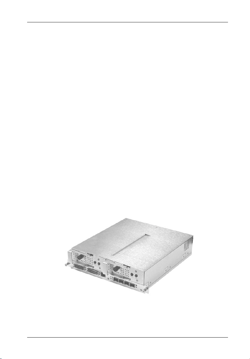
The StorCase Technology 2Gbps Fibre Channel-to-SCSI Ultra160 (FC-to-SCSI) Dual
RAID Controller Module option (P/N S10C104) is specifically designed for the InfoStation
external expansion chassis. The FC-to-SCSI Dual RAID Controller Module (Figure 1) is a dual
Fibre Channel host port controller with four (4) SCSI disk channels (supporting 2x4 configurations).
StorCase Technology, Inc. FC-SCSI Dual RAID Module User's Guide - Rev. A01
Page 16
Introduction 3
Product Features:
Superior performance in single and dual controller module configurations
Convenient, Dual Hot-Pluggable Controller Modules
Dual 2Gbps FC Host, quad SCSI Ultra160 Channel (2x4) Configuration
Active-Active or Active-Passive Failover Configurability
Supports 1Gbps or 2Gbps Fibre Channel Arbitrated Loop (FC-AL)
Supports 1Gbps or 2Gbps Fibre Channel Switch Fabric (FC-SW)
Supports RAID Levels 0, 1, 0/1, 3, 4, 5, 10, 50, or JBOD
Online Capacity Expansion (OCE) allows adding drives without interruptions
128MB of PC-133 Compatible SDRAM DIMM Cache Memory
NiMH Fast Charging Battery for Cache Back-up
Supports up to 60 Devices; up to 24 Arrays; up to 64 LUNs
Data Transfer Rate of Over 18,000 IOPS
OS-Independent
Downward-compatible with 80MB/sec LVD and Single-Ended Modes
Includes RJ45-DB9 serial cable for system integration & monitoring
Optional SFP cable kits available
This User's Guide describes the basic steps required to install the StorCase InfoStation
FC-to-SCSI Dual RAID Controller Module unit inside the InfoStation external expansion chassis.
This guide supplements documentation provided with the InfoStation.
IFSII_FDR2
Figure 1: FC-to-SCSI Dual RAID Controller Module Unit
FC-SCSI Dual RAID Module User's Guide - Rev. A01 StorCase Technology, Inc.
Page 17

4 Introduction
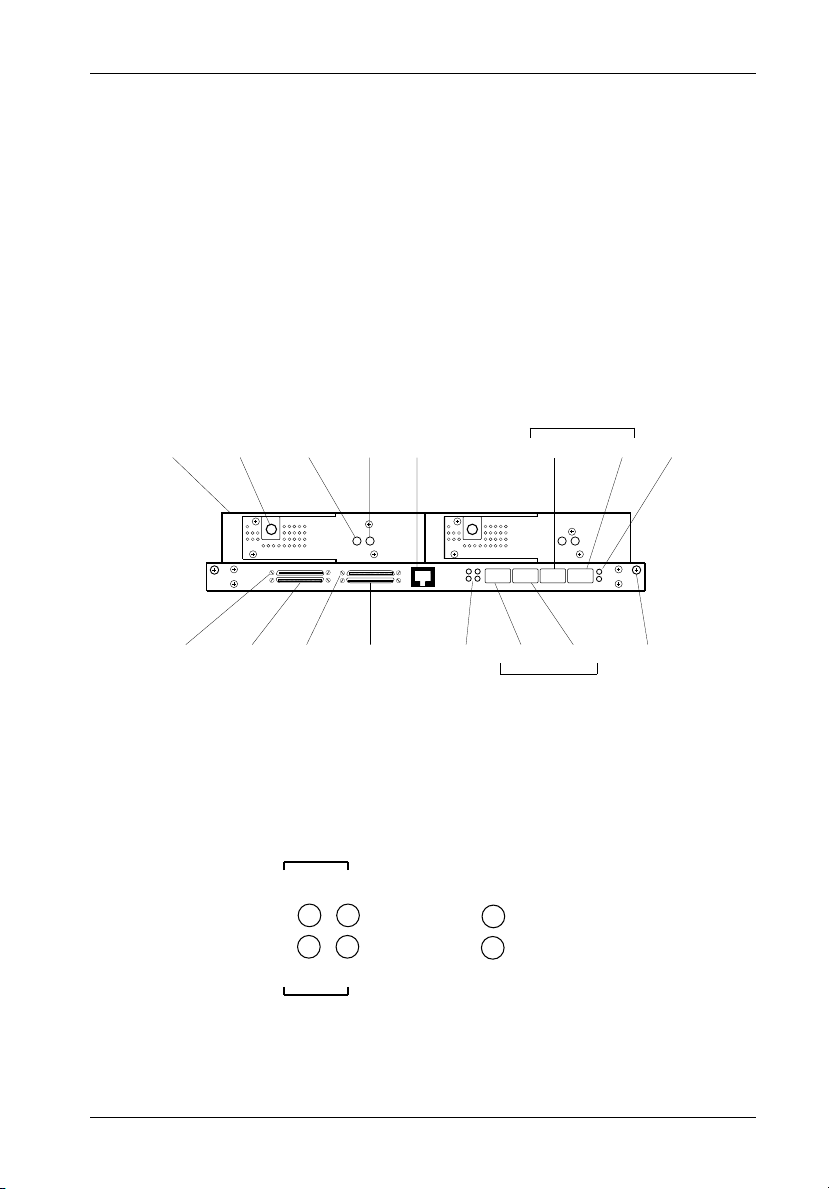
Dual RAID Controller Module Unit Panel
(Figure 2A)
RAID Controller A - Primary RAID controller
RAID Controller B - Secondary RAID controller
RAID Controller A
Host 0 - Connects to FC Host 0
Host 1 - Connects to FC Host 1
RAID Controller B
Host 0 - Connects to FC Host 0
Host 1 - Connects to FC Host 1
Disk Channel 0 - Connects to InfoStation I/O repeater module #1
Disk Channel 1 - Connects to InfoStation I/O repeater module #2
Disk Channel 2 - Connects to InfoStation I/O repeater module #3
Disk Channel 3 - Connects to InfoStation I/O repeater module #4
Cache LED (Green) - Provides the following information:
ON = Indicates that data is in Cache Memory
OFF= Indicates that data write to disk is complete
Fault LED (Red) - Provides the following information.
Flashing indicates a fan failure in either RAID Controller A or B (the InfoStation UI will
also display an error message).
Steady glow indicates a fault condition with the RAID Controller (the InfoStation UI will
also display an error message).
RS-232 Serial Port (RAID Configuration Port) - Connects to a VT-100/ANSI terminal
via an RJ45-DB9 cable (provided). Refer to section "Configuration" for further
information.
LEDs (Figure 2B) - Provide the following information:
Activity
B1 - ON = Indicates FC-AL is detected on Controller B FC Host 1
B0 - ON = Indicates FC-AL is detected on Controller B FC Host 0
A1 - ON = Indicates FC-AL is detected on Controller A FC Host 1
A0 - ON = Indicates FC-AL is detected on Controller A FC Host 0
NOTE: Flashing indicates activity.
StorCase Technology, Inc. FC-SCSI Dual RAID Module User's Guide - Rev. A01
Page 18
Introduction 5
2Gb/s ON = 2Gbps operation
OFF = 1Gbps operation
NOTES: HSSDC2 (copper) SFP modules support 1Gbps operation only.
LC (optical) SFP modules support both 2Gbps and 1Gbps operation.
RS-232 ON = RS-232 port is DISABLED.
DISABLED OFF = RS-232 port is ENABLED.
Eject
Handle
RAID Controller B
(Secondary)
Disk
Ch. 3
Locking
Thumbscrew
Disk
Ch. 2
Cache
LED
Disk
Ch. 1
Fault
LED
Disk
Ch. 0
RS-232
Serial Port
LEDs
RAID Controller A
Host 1
Host 0
Host 1
RAID Controller B
Host 0
IFSII_FDR1
Captive
Screw
LEDs
RAID Controller A
Figure 2A: FC-to-SCSI Dual RAID Controller Module Unit Panel
B0 A0
2Gb/s
RS-232
A C T I V I T Y
A1
B1
DISABLED
IFSII_FDR3
(Primary)
Figure 2B: Enlarged View of LEDs
FC-SCSI Dual RAID Module User's Guide - Rev. A01 StorCase Technology, Inc.
Page 19

6 Installation
INSTALLATION
CAUTION: Remove ALL power from the InfoStation before installing the Dual RAID
WARNING: Danger of explosion if the RAID battery is incorrectly replaced! Replace
NOTES: The installation, configuration, and use of the Fibre-to-SCSI Dual RAID
Controller Module unit. The RAID Controller Module contains NO USER
SERVICEABLE PARTS inside. Warranty is VOID if module is opened.
Refer ALL servicing to qualified service personnel!
DO NOT bend the LC (optical) cable beyond the cable's minimum bend
radius, data transmission degradation may occur. Follow cable manufacturer's guidelines for bend radius limitation.
VHDCI connectors are easily damaged by improper handling. Visually
inspect each connector for bent contacts and carefully align prior to
insertion.
only with the same or equivalent type recommended by the manufacturer.
Dispose of used batteries according to manufacturer's instructions.
DO NOT look directly into the open end of an active LC (optical) cable or
optical SFP module (with plugs removed)! Serious eye damage can occur
from direct exposure to the infrared light!
Controller Module option requires a certain level of expertise and experience on the part of the user/integrator. Since there are many configuration
options and variables (ie. host platforms, applications, etc.), only general
guidelines will be discussed in this User's Guide.
For stand-alone configurations, the Single RAID Controller Module should
be installed in the Controller A (Primary) location only.
HSSDC2 (copper) SFP modules support 1Gbps operation only.
LC (optical) SFP modules support both 2Gbps and 1Gbps operation.
FC-to-SCSI RAID Controller Module will only work with InfoStation UI F/W
Rev. 2.0.11 or higher.
Refer to both the InfoStation User's Guide and Installation Guide for
additional operating and installation information. Also refer to the disk
manufacturer's documentation for information regarding the disks.
StorCase Technology, Inc. FC-SCSI Dual RAID Module User's Guide - Rev. A01
Page 20
Installation 7
Installing the Dual RAID Controller Module Unit into the InfoStation
Please refer to the InfoStation Installation Guide for information regarding the installation of
the Dual RAID Controller Module unit into the InfoStation.
Installing the RAID Battery Backup Unit(s) into the InfoStation
CAUTION: Remove ALL power from the InfoStation before installing the RAID
Battery Module(s). The RAID Controller Module unit contains NO USER
SERVICEABLE PARTS inside. Warranty is VOID if module is opened.
Refer ALL servicing to qualified service personnel!
Danger of explosion if the RAID battery is incorrectly replaced! Replace
only with the same or equivalent type recommended by the manufacturer.
Dispose of used batteries according to the manufacturer's instructions.
NOTE: While performing the steps in this section, work on a soft surface to
prevent excessive shock to the RAID Controller Module and InfoStation II
chassis.
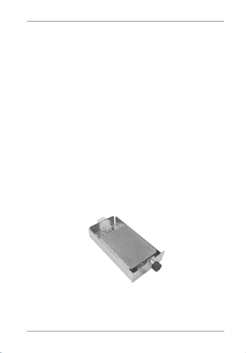
The Dual RAID Controller Module unit comes with two RAID Battery Backup Units (the Single
RAID Module unit only comes with one). The Battery Backup Unit (Figure 3) provides writeback
cache backup power to the RAID Controller Module unit should the power fail for any reason.
IFSII_DR10
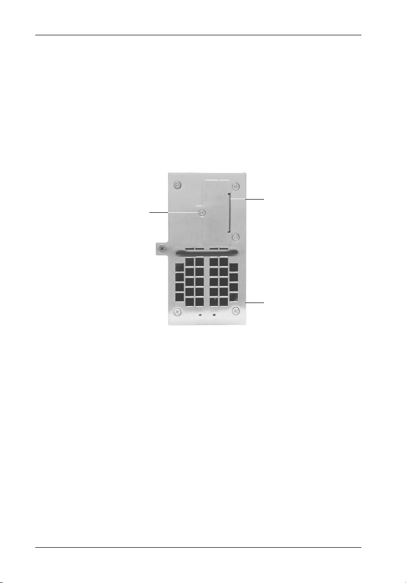
Figure 3: RAID Battery Backup Unit
FC-SCSI Dual RAID Module User's Guide - Rev. A01 StorCase Technology, Inc.
Page 21
8 Installation
To install the RAID Battery Backup Unit(s):
1. Loosen and remove the #6-32 Phillips F.H. screw securing the blank plate to the
Blower Module (Figure 4). Remove blank plate.
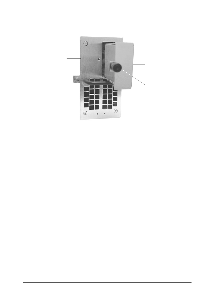
2. Install the RAID Battery Backup Unit into the blower module (Figure 5).
3. Tighten the thumbscrew to secure the Battery Backup Unit in place.
Blank
#6-32 Phillips
F.H. Screw
IFSII_DR8
Plate
Blower
module
Figure 4: Installation Location of RAID Battery Backup Unit
StorCase Technology, Inc. FC-SCSI Dual RAID Module User's Guide - Rev. A01
Page 22
Installation 9
Blower
Module
IFSII_DR9
RAID Battery
Backup Unit
Thumbscrew
Figure 5: Installing the RAID Battery Backup Unit into the Blower Module
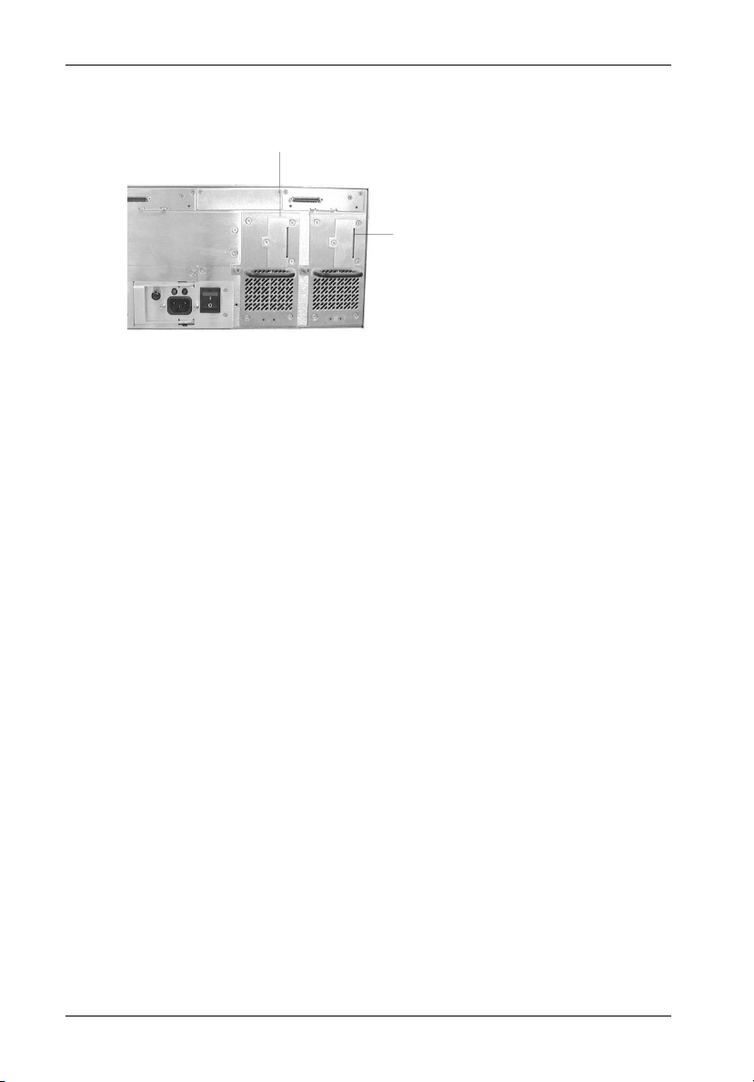
If installing only one (1) RAID Battery Backup Unit (for use with the Single RAID Controller Module
unit), the Battery Backup Unit must be installed into the correct blower module. Refer to Figure
6 for correct Battery Backup Unit installation locations.
NOTE: In case of blower module failure, be sure to reinstall the RAID Battery Backup Unit(s)
into the replacement blower module!
FC-SCSI Dual RAID Module User's Guide - Rev. A01 StorCase Technology, Inc.
Page 23
10 Installation
Battery Location for
RAID Controller B
Battery Location for RAID Controller A
NOTE: For Single RAID Module
IFSII_DR11
configurations, install
battery backup unit in this
blower module ONLY!
NOTE: For Dual RAID Module configurations, install
battery backup units in each blower module
Figure 6: RAID Battery Backup Unit Installation Location
StorCase Technology, Inc. FC-SCSI Dual RAID Module User's Guide - Rev. A01
Page 24

Installation 11
DUAL RAID CHANNEL CONFIGURATIONS
CAUTION: Offset VHDCI cable connectors must be used for proper fit. Failure to use
NOTES: StorCase recommends the use of SCSI Ports A-1 & A-2 on the I/O Repeater
proper cables may result in damage to the VHDCI connectors on the I/O
repeater modules and Dual RAID Controller Module unit! RAID Controller
"Kits" containing external I/O cables are available; contact StorCase for
further ordering information.
VHDCI connectors are easily damaged by improper handling. Visually
inspect each connector for bent contacts and carefully align prior to
insertion.
Modules when configuring typical RAID channels (as shown in Figures
7, 8, & 9). In the special cases where extra length cables are required
(up to 12m maximum), use Port B instead.
Controller A (Primary) disk channel SCSI ID (Initiator ID) is factory set to
SCSI ID7. DO NOT configure any other devices to ID7 on the disk channel,
or the configuration will fail to operate!
Controller B (Secondary) disk channel SCSI ID (Initiator ID) is factory set
to SCSI ID6. DO NOT configure any other devices to ID6 on the disk channel,
or the configuration will fail to operate!
StorCase does not recommend changing the factory default Initiator ID(s).
Up to 15 disks per SCSI channel with stand-alone RAID Controller Module
unit installed (15 Disks x 4 Channels = 60 Disks Total).
Up to 14 disks per SCSI channel with dual RAID Controller Module unit
installed (14 Disks x 4 Channels = 56 Disks Total).
Default operating mode for the Dual RAID Controller Module unit is Active-
Passive.
Default operating mode for the Single RAID Controller Module unit is Stand-
Alone Dual Port.
Default operating mode for the Single RAID Controller Module upgrade is
Stand-Alone Dual Port.
If upgrading a Single RAID Controller Module unit with the Single RAID
Controller Module upgrade (to a Dual RAID Controller Module configuration), make sure to reconfigure the operating mode accordingly.
I/O Repeater Modules must be used in conjunction with the FC-to-SCSI
RAID Controller Module unit.
FC-SCSI Dual RAID Module User's Guide - Rev. A01 StorCase Technology, Inc.
Page 25
12 Installation
CAUTION: DO NOT bend the LC (optical) cable beyond the cable's minimum bend
radius, data transmission degradation may occur. Follow cable manufacturer's guidelines for bend radius limitation.
WARNING: DO NOT look directly into the open end of an active LC (optical) cable or
optical SFP module (with plugs removed)! Serious eye damage can occur
from direct exposure to the infrared light!
NOTES: HSSDC2 (copper) SFP modules support 1Gbps operation only.
LC (optical) SFP modules support both 2Gbps and 1Gbps operation.
When in Active-Active mode, the dual controllers communicate with each other
using SCSI Initiator IDs 6 & 7 on the disk channels. IDs 6 & 7 are factory set to ensure
optimum communication between the two controllers. These IDs cannot be
changed while in Active-Active mode. DO NOT configure any other devices to IDs
6 & 7 on the disk channels, or the Active-Active configuration will fail to operate!
Refer to section "Working with Operating Modes" for further information on Operating Modes.
Table 1: Operating Mode Settings
Configuration
Single RAID
Module Unit
Dual RAID
Module Unit
Dual RAID
Module Unit
Dual RAID
Module Unit
Host Channel
Setting
Stand-Alone
Dual Port
Active-Active
Single Port
Active-Active
Dual Port
Active-Passive
Dual Port
Description
This option allows the controller to operate with two host ports. In
this mode, the same LUNs display on the two separate host ports.
Stand-Alone Dual Port mode allows the host to achieve greater
throughput by balancing I/O operations across the two host ports.
Host port fault tolerance is also achieved, since the host can continue accessing the controller if one host channel fails.
This option allows both controllers to operate independently and
in an active-active pair. Active-Active modes allow two controllers
to cooperate in system operation in a fault-tolerant manner. If one
controller fails while in Active-Active mode, the other controller
assumes its activities, allowing host access to continue.
When both controllers are online, each controller presents its
LUNs on only one port.
This option allows both controllers to operate independently and
in an active-active pair. Active-Active modes allow two controllers
to cooperate in system operation in a fault-tolerant manner. If one
controller fails while in Active-Active mode, the other controller
assumes its activities, allowing host access to continue.
When both controllers are online, each controller presents its
LUNs on both ports, permitting redundant host access to all LUNs
when there is a failure between host and controller. After failover,
one port of the surviving controller presents Controller As LUNs
and other port presents Controller Bs LUNs.
When changing to this mode on one controller, both controllers
must be rebooted at the same time. Upon reboot, both controllers
will automatically be in Active-Active Dual Port mode
This option allows the use of just one controller, with the second
controller acting only as a backup (in case of a failure of the controller in use).
When changing to this mode on one controller, both controllers
must be rebooted at the same time. Upon reboot, both controllers
will automatically be in Active-Passive Dual Port mode
IFSII_FDR21
StorCase Technology, Inc. FC-SCSI Dual RAID Module User's Guide - Rev. A01
Page 26
Installation 13
NOTES: For stand-alone configurations, the Single RAID Controller Module should be installed in
the Controller A (Primary) location only.
For stand-alone configurations, only RAID Controller A Host ports should be used to connect to FC Hosts 0 & 1. RAID Controller B Host ports are for loop expansion only.
Auto Loopback is enabled when there are no SFP Modules installed in the open Host ports.
Cover plate (provided) must be installed if module slot is left empty. Installation of
cover plate is necessary for proper cooling inside chassis.
Up to 15 disks per SCSI Channel with Single RAID Controller Module Unit installed.
(15 Disks x 4 Channels = 60 Disks Total)
Disk Ch. 3
(3 Drives)
T
14-Bay InfoStation
(Single RAID Controller Module Installed)
FC HBA
Host 1
Disk Ch. 2
(4 Drives)
FC-AL #2
Disk Ch. 1
(3 Drives)
T
T
FC-AL #1
Disk Ch. 0
(4 Drives)
FC HBA
Host 0
T
IFSII_FDR8
= No SFP
Module Installed
(Auto-Loopback)
= SFP Module
PC
Installed
T
= SCSI Terminator
PC
Figure 7A: Typical Stand-Alone Single RAID, Dual Loop Configuration
(Single 14-Bay Chassis with Single RAID Controller Module Unit Installed)
FC-SCSI Dual RAID Module User's Guide - Rev. A01 StorCase Technology, Inc.
Page 27
14 Installation
NOTES: For stand-alone configurations, the Single RAID Controller Module should be installed in
the Controller A (Primary) location only.
For stand-alone configurations, only RAID Controller A Host ports should be used to connect to FC Hosts 0 & 1. RAID Controller B Host ports are for loop expansion only.
Auto Loopback is enabled when there are no SFP Modules installed in the open Host ports.
Cover plate (provided) must be installed if module slot is left empty. Installation of
cover plate is necessary for proper cooling inside chassis.
Up to 15 disks per SCSI Channel with Single RAID Controller Module Unit installed.
(15 Disks x 4 Channels = 60 Disks Total)
T
14-Bay InfoStation JBOD
Disk Ch. 3
(3 Drives)
Disk Ch. 2
(4 Drives)
T
Disk Ch. 1
(3 Drives)
T
T
Disk Ch. 0
(4 Drives)
14-Bay InfoStation
(Single RAID Controller Module Installed)
FC HBA
Host 1
FC-AL #2 FC-AL #1
PC
= No SFP
Module Installed
(Auto-Loopback)
= SFP Module
Installed
T
= SCSI Terminator
FC HBA
IFSII_FDR7
Host 0
PC
Figure 7B: Typical Stand-Alone Single RAID, Dual Loop Configuration
(Multiple 14-Bay Chassis with Single RAID Controller Module Unit Installed)
StorCase Technology, Inc. FC-SCSI Dual RAID Module User's Guide - Rev. A01
Page 28
Installation 15
NOTES: For stand-alone configurations, the Single RAID Controller Module should be installed in
the Controller A (Primary) location only.
For stand-alone configurations, only RAID Controller A Host ports should be used to connect to FC Hosts 0 & 1. RAID Controller B Host ports are for loop expansion only.
Auto Loopback is enabled when there are no SFP Modules installed in the open Host ports.
Cover plate (provided) must be installed if module slot is left empty. Installation of
cover plate is necessary for proper cooling inside chassis.
Up to 15 disks per SCSI Channel with Single RAID Controller Module Unit installed.
(15 Disks x 4 Channels = 60 Disks Total)
T
14-Bay InfoStation JBOD
Disk Ch. 3
(3 Drives)
Disk Ch. 2
(4 Drives)
T
Disk Ch. 1
(3 Drives)
T
T
Disk Ch. 0
(4 Drives)
FC-AL #2
FC-AL #1
Loop Expansion
14-Bay InfoStation
(Single RAID Controller Module Installed)
FC HBA
Host 1
FC-AL #2 FC-AL #1
PC
= SFP Module
Installed
T
= SCSI Terminator
FC HBA
Host 0
IFSII_FDR7A
PC
Figure 7C: Typical Stand-Alone Single RAID, Dual Loop Configuration
with Optional Loop Expansion
(Multiple 14-Bay Chassis with Single RAID Controller Module Unit Installed)
FC-SCSI Dual RAID Module User's Guide - Rev. A01 StorCase Technology, Inc.
Page 29
16 Installation
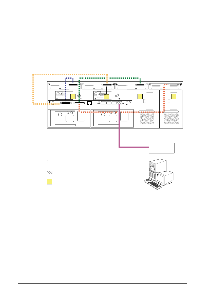
NOTE: Up to 14 disks per SCSI Channel with Dual RAID Controller Module Unit installed.
(14 Disks x 4 Channels = 56 Disks Total)
Auto Loopback is enabled when there are no SFP Modules installed in the open Host ports.
Disk Ch. 3
(3 Drives)
T
14-Bay InfoStation
(Dual RAID Controller Module Installed)
= No SFP
Module Installed
(Auto-Loopback)
= SFP Module
Installed
T
= SCSI Terminator
Disk Ch. 2
(4 Drives)
Disk Ch. 1
(3 Drives)
T
T
FC-AL #1
Disk Ch. 0
(4 Drives)
FC HBA
Host 0
T
IFSII_FDR5
PC
Figure 8A: Typical Dual RAID, Single Host, Single Loop Configuration
(Single 14-Bay Chassis with Dual RAID Controller Module Unit Installed)
StorCase Technology, Inc. FC-SCSI Dual RAID Module User's Guide - Rev. A01
Page 30
Installation 17
NOTE: Up to 14 disks per SCSI Channel with Dual RAID Controller Module Unit installed.
(14 Disks x 4 Channels = 56 Disks Total)
Auto Loopback is enabled when there are no SFP Modules installed in the open Host ports.
PC
Disk Ch. 2
(4 Drives)
FC-AL #2
T
= No SFP
Module Installed
(Auto-Loopback)
= SFP Module
Installed
T
= SCSI Terminator
Disk Ch. 1
(3 Drives)
FC-AL #1
Disk Ch. 0
(4 Drives)
T
FC HBA
Host 0
Disk Ch. 3
(3 Drives)
T
14-Bay InfoStation
(Dual RAID Controller Module Installed)
FC HBA
Host 1
T
IFSII_FDR26
PC
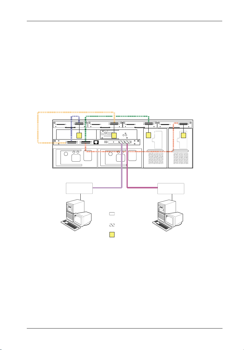
Figure 8B: Typical Dual RAID, Dual Host, Dual Loop Configuration
(Single 14-Bay Chassis with Dual RAID Controller Module Unit Installed)
FC-SCSI Dual RAID Module User's Guide - Rev. A01 StorCase Technology, Inc.
Page 31

18 Installation
NOTE: Up to 14 disks per SCSI Channel with Dual RAID Controller Module Unit installed.
(14 Disks x 4 Channels = 56 Disks Total)
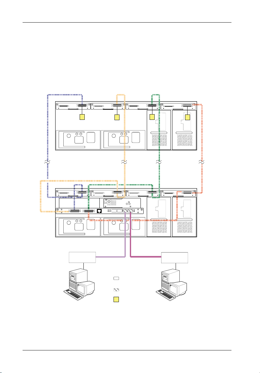
SFP Modules installed in Controller B Host ports allow for Loop Expansion.
Disk Ch. 3
(3 Drives)
T
Disk Ch. 2
(4 Drives)
Disk Ch. 1
(3 Drives)
T
T
Disk Ch. 0
(4 Drives)
FC-AL #2
FC-AL #1
14-Bay InfoStation
(Dual RAID Controller Module Installed)
FC HBA
Host 1
FC-AL #2
FC-AL #1
FC HBA
Host 0
Loop Expansion
T
IFSII_FDR26A
= SFP Module
Installed
T
PC
= SCSI Terminator
PC
Figure 8C: Typical Dual RAID, Dual Host, Dual Loop Configuration
with Optional Loop Expansion
(Single 14-Bay Chassis with Dual RAID Controller Module Unit Installed)
StorCase Technology, Inc. FC-SCSI Dual RAID Module User's Guide - Rev. A01
Page 32

Installation 19
NOTE: Up to 14 disks per SCSI Channel with Dual RAID Controller Module Unit installed.
(14 Disks x 4 Channels = 56 Disks Total)
Auto Loopback is enabled when there are no SFP Modules installed in the open Host ports.
Disk Ch. 3
(3 Drives)
T
14-Bay InfoStation
(Dual RAID Controller Module Installed)
FC HBA
Host 1
Disk Ch. 2
(4 Drives)
Disk Ch. 1
(3 Drives)
T
FC-AL #1 FC-AL #1
Disk Ch. 0
(4 Drives)
T
FC HBA
Host 0
LAN Segment
T
IFSII_FDR27
= No SFP
PC
Module Installed
(Auto-Loopback)
= SFP Module
Installed
T
= SCSI Terminator
PC
Figure 8D: Typical Dual RAID, Dual Host, Single Loop Configuration for Clustering
(Single 14-Bay Chassis with Dual RAID Controller Module Unit Installed)
FC-SCSI Dual RAID Module User's Guide - Rev. A01 StorCase Technology, Inc.
Page 33

20 Installation
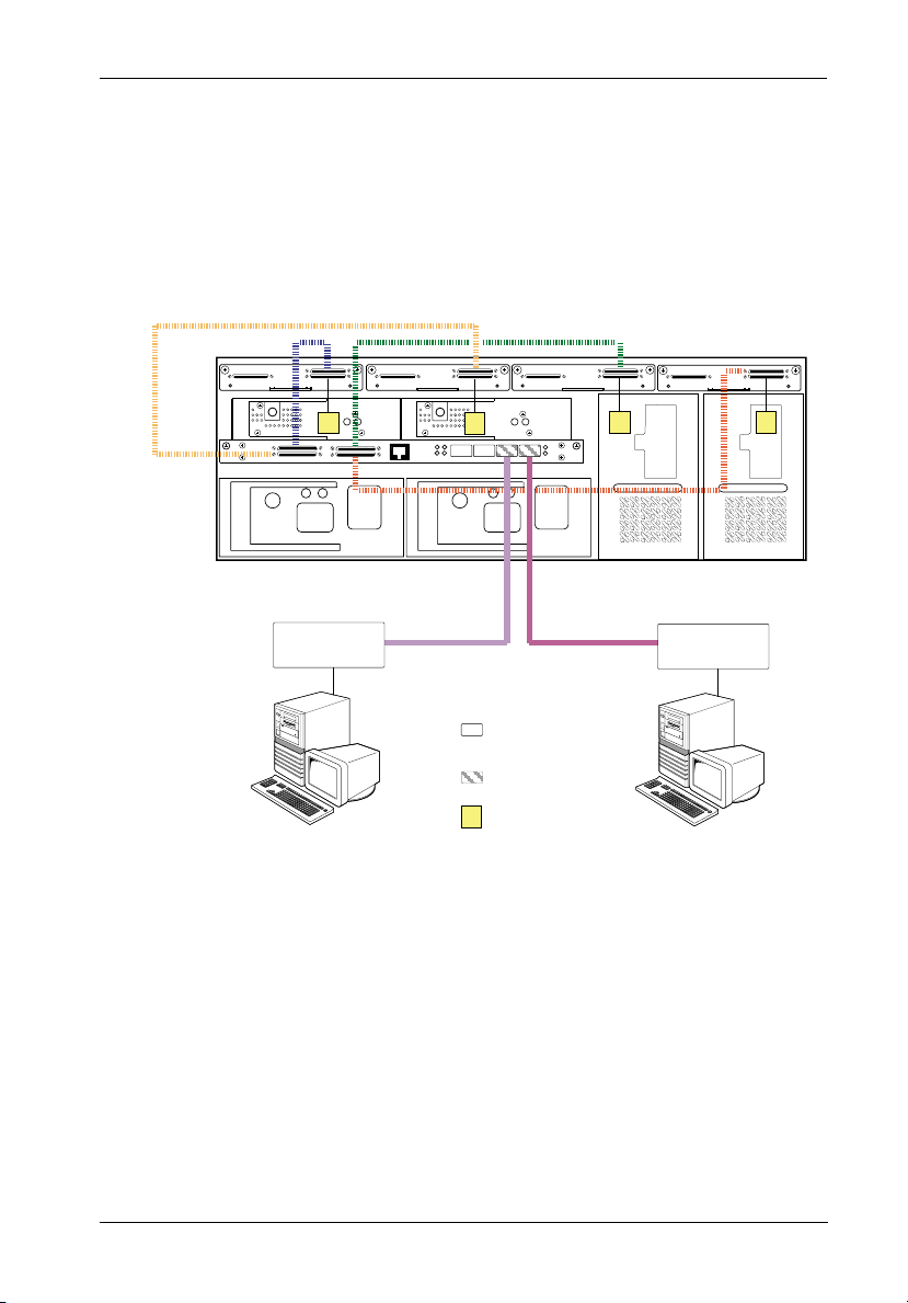
NOTE: Up to 14 disks per SCSI Channel with Dual RAID Controller Module Unit installed.
(14 Disks x 4 Channels = 56 Disks Total)
Disk Ch. 3
(3 Drives)
Disk Ch. 2
(4 Drives)
T
14-Bay InfoStation
(Dual RAID Controller Module Installed)
FC HBA
FC-AL #2
Disk Ch. 1
(3 Drives)
T
T
Disk Ch. 0
(4 Drives)
FC-AL #1
FC HBA
FC-AL #2FC-AL #1
LAN Segment
T
IFSII_FDR28
PC
= SFP Module
Installed
T
= SCSI Terminator
PC
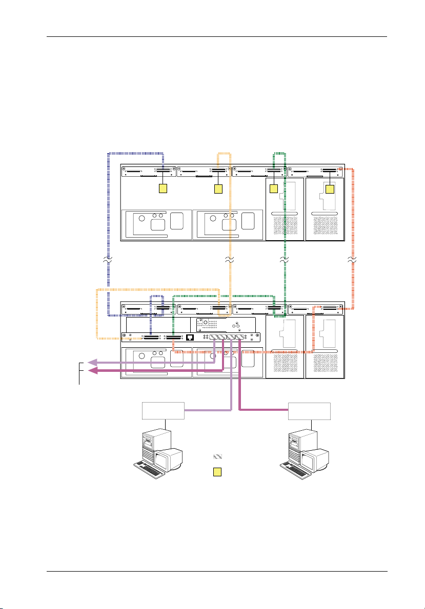
Figure 9A: Typical Dual RAID, Dual Host, Dual Loop Configuration for Clustering
(Single 14-Bay Chassis with Dual RAID Controller Module Unit Installed)
StorCase Technology, Inc. FC-SCSI Dual RAID Module User's Guide - Rev. A01
Page 34

Installation 21
NOTE: Up to 14 disks per SCSI Channel with Dual RAID Controller Module Unit installed.
(14 Disks x 4 Channels = 56 Disks Total)
T
14-Bay InfoStation JBOD
Disk Ch. 3
(3 Drives)
Disk Ch. 2
(4 Drives)
Disk Ch. 1
(3 Drives)
T
T
T
Disk Ch. 0
(4 Drives)
14-Bay InfoStation
(Dual RAID Controller Module Installed)
FC-AL #2
FC HBA
FC-AL #1
IFSII_FDR29
FC HBA
FC-AL #2FC-AL #1
LAN Segment
PC
= SFP Module
Installed
T
= SCSI Terminator
PC
Figure 9B: Typical Dual RAID, Dual Host, Dual Loop Configuration for Clustering
(Multiple 14-Bay Chassis with Dual RAID Controller Module Unit Installed)
FC-SCSI Dual RAID Module User's Guide - Rev. A01 StorCase Technology, Inc.
Page 35

22 Configuration
CONFIGURATION
Configuration Overview
To configure the FC-to-SCSI Dual RAID Controller Module unit, run the Administrator Utility via
a computer serial port (cable provided). This utility allows the user to:
Create arrays
Delete arrays
Monitor array statistics
Verify array integrity
Change array configurations
Monitor drive failures and use spare drives
Monitor controller environmental, configuration, and status information
Starting the Administrator Utility
NOTES: Microsoft® Windows® 3.x and Windows® NT 3.5x include a program called Terminal
which does not support ANSI color. If using either O/S, select VT-100 for terminal
emulation or use a third-party software program such as Procomm for Windows.
Microsoft® Windows® 95/98/NT/2000 includes a program called HyperTerminal that
supports ANSI color.
FC-to-SCSI RAID Controller Module will only work with InfoStation UI F/W Rev. 2.0.11
or higher.
The Administrator Utility is implemented with a VT-100 or ANSI terminal connected through the
RS-232 serial port on the Dual RAID Controller Module unit (Figure 2A). This utility is embedded
in the firmware; software loading is not required unless for upgrade purposes.
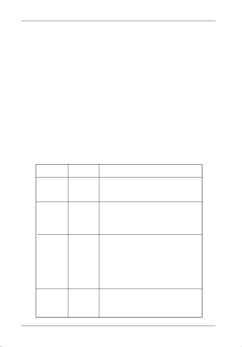
The Administrator Utility can also be implemented through the RS-232 serial port on the
InfoStation User Interface Module, as shown in Figure 10. This is especially convenient in rackmount environments where it may be difficult to access the Dual RAID Controller Module unit
directly.
RS-232
Serial Port
IFS_6a
Figure 10: InfoStation User Interface Module
StorCase Technology, Inc. FC-SCSI Dual RAID Module User's Guide - Rev. A01
Page 36

Configuration 23
InfoStation Serial Port Set-Up
To access the Administrator Utility via the UI Module RS-232 serial port, the user must first
configure the Serial Port Set-Up in the UI Module (see below).
Refer to the InfoStation User's Guide (specifically, sections "InfoStation User Interface" and
"Serial Port Set-Up") for further information.
NOTES: Press CANCEL at anytime to exit the menu system and return to the Default
T E M P : x x C
ENTER
S t a t u s
DOWN
S e t u p
Display. The menu system will automatically cancel after 15 seconds of
User inactivity.
Factory default is S.Port0.
1. Press ENTER at the Default Display so that
display = Status.
2. Press DOWN until display = Setup.
ENTER
E n c . I D
DOWN
S e r . P o r t
ENTER
S - P o r t = 0
UP/DOWN
S - P o r t = 1
ENTER
S - P o r t = 1
3. Press ENTER so that display = Enc. ID.
4. Press DOWN until display = Ser.Port
5. Press ENTER so that display = S-Portx .
This is the current serial port set-up.
6. Press UP or DOWN to change the serial port
option.
7. Press ENTER to accept the change.
The following lists each InfoStation serial port option and its description.
S.Port0 = InfoMon monitoring via the UI Module Serial Port (refer to the InfoMon User's
Guide for further information).
S.Port1 = RAID configuration through the Primary RAID Controller Module via the
UI Module Serial Port.
S.Port2 = RAID configuration through the Secondary RAID Controller Module via the
UI Module Serial Port.
FC-SCSI Dual RAID Module User's Guide - Rev. A01 StorCase Technology, Inc.
Page 37

24 Configuration
S.Port3 = RAID configuration through the Primary RAID Controller Module via the
RAID Controller Module Serial Port.
InfoMon can also be monitored simultaneously via the UI Module Serial Port.
S.Port4 = RAID configuration through the Secondary RAID Controller Module via the
RAID Controller Module Serial Port.
InfoMon can also be monitored simultaneously via the UI Module Serial Port.
InfoStation Fibre Channel Speed Set-Up
The following steps show how to change the InfoStation Fibre Channel Speed. Refer to the
InfoStation User's Guide (specifically, sections "InfoStation User Interface" and "Fibre
Channel Speed Set-Up") for further information.
Fibre Channel speed must also be set in the RAID Controller and FC HBA (refer to section
"Configuring the Host Channels" and FC HBA documentation for further information).
NOTES: Press CANCEL at anytime to exit the menu system and return to the Default
T E M P : x x C
Display. The menu system will automatically cancel after 15 seconds of
User inactivity.
FC Speed 0 = 1Gbps
FC Speed 1 = 2Gbps (Factory Default)
ENTER
S t a t u s
DOWN
S e t u p
ENTER
E n c . I D
DOWN
F C S p e e d
ENTER
F C S P D = 1
UP/DOWN
F C S P D = 0
ENTER
F C S P D = 0
1. Press ENTER at the Default Display so that
display = Status.
2. Press DOWN until display = Setup.
3. Press ENTER so that display = Enc. ID.
4. Press DOWN until display = FC Speed.
5. Press ENTER so that display = FC SPD=1.
This is the current Fibre Channel speed.
6. Press UP or DOWN to change the Fibre Channel
speed.
7. Press ENTER to accept the change.
StorCase Technology, Inc. FC-SCSI Dual RAID Module User's Guide - Rev. A01
Page 38

Configuration 25
To find HyperTerminal in Windows:
1. Click on Start (normally located at the bottom left of the Windows desktop)
2. Go to Programs
3. Go to Accessories
4. Go to HyperTerminal
Set the preferences as follows:
Table 2: Terminal Program Preferences
Setting
Terminal Emulation
Font
Translations
Columns
Set the communications parameters as follows:
Table 3: Terminal Program Communications Parameters
Setting
Baud Rate
Data Bits
Stop Bits
Parity
Flow Control
Connector
Value
VT-100 or ANSI
Terminal
None
80
Value
115,200
8
1
None
None
COM1
(typical)
IFS_46
IFS_47
FC-SCSI Dual RAID Module User's Guide - Rev. A01 StorCase Technology, Inc.
Page 39

26 Configuration
Once the Dual RAID Controller Module unit is booted and the preferences have been set, a
screen (Figure 11) appears displaying the following information:
Controller
Configuration
Array information
Time/Date
Board Temperature
Press Enter to display the Administrator Utility System Menu Screen (Figure 12).
Figure 11: Boot-Up Screen
StorCase Technology, Inc. FC-SCSI Dual RAID Module User's Guide - Rev. A01
Page 40

Configuration 27
Figure 12: Administrator Utility System Menu
Selecting Menu Options
NOTE: The Administrator Utility has an Online Help option. Enabling this option (Ctrl-H) after
setting the terminal mode and color is highly recommended!
Use the following information to navigate through the Administrator Utility menu options:
Table 4: Selecting Menu Options
Menu Options
Exit
Move Up
Move Down
Select
Refresh
(between ANSI or
Toggle
VT-100 modes)
Color Toggle
Event Log
(HW info screen)
Enable Online Help
Press
Esc or or Ctrl-Z
Enter
Ctrl-R
Ctrl-A
Ctrl-B
Ctrl-E
Ctrl-H
IFS_48
FC-SCSI Dual RAID Module User's Guide - Rev. A01 StorCase Technology, Inc.
Page 41

28 Configuration
Creating and Managing Arrays and Partitions
Using the Disk Array Administrator, the user can create and manage arrays and partitions.
The following array-related functions can be performed:
Create arrays
Manage arrays
Manage partitions
Creating Arrays
NOTE: Before creating more than one array, make sure that the host operating system
supports multiple LUNs. Most operating systems do, or have an option to enable
multiple LUN support. If the host system does not support multiple LUNs, the host
will only see one array at LUN 0.
An array can be created at anytime. Table 5 below describes the drive requirements for each
RAID level.
Table 5: Drive Requirements for each RAID Level
RAID Level Min. # of Drives Max. # of Drives
0
3
4
5
50 6
Mirrored
Volume Set
2
3
3
3
2
11
15
15
15
15
30
15
IFSII_FDR15
NOTE: Up to 15 disks per SCSI channel with Single FC-to-SCSI RAID Controller Module Unit
installed (15 Disks x 4 Channels = 60 Disks Total).
Up to 14 disks per SCSI channel with Dual FC-to-SCSI RAID Controller Module Unit
installed (14 Disks x 4 Channels = 56 Disks Total).
StorCase Technology, Inc. FC-SCSI Dual RAID Module User's Guide - Rev. A01
Page 42

Configuration 29
Before an array is created, the user must decide whether or not to partition the array. There
are two (2) ways to partition an array:
1. Single-partition array - an array that stores all data in a single partition and is ac-
2. Multiple-partition array - an array that can have one or more partitions, with each
Refer to section "Understanding Partitions" for further information
cessed by a single LUN.
partition assigned its own LUN.
Creating a Single-Partition Array
This function allows the user to create single-partition arrays. Once a single-partition array
has been created, more partitions can be added later. Single-partition arrays work well in
environments that need one large, fault-tolerant storage space for data on one server.
To create a single-partition array:
1. Select Add an Array from the System Menu and press Enter.
The Enter Array Name screen should now display (Figure 13).
Figure 13: Enter Array Name Screen
FC-SCSI Dual RAID Module User's Guide - Rev. A01 StorCase Technology, Inc.
Page 43

30 Configuration
2. Enter a name for the array and press Enter.
Up to 20 characters (any character, including spaces) can be used. If no name is to
be used, just press Enter (a name may be added or changed later).
The system will now ask if you want to create one partition for the entire array.
3. Select Yes to create a single-partition array and press Enter (for creating multiple-
partition arrays, refer to section "Creating a Multiple-Partition Array" for further
information).
The LUN screen should now display (Figure 14).
The LUN displayed is the suggested default LUN assignment.
Figure 14: Array LUN Screen
4. Select the LUN for the array and press Enter.
If the letters OV appear before a LUN, this indicates that the selection overlaps with
a soft LUN, most likely the controller or SAF-TE Environmental Processor (SEP) LUN.
An array at an overlapped LUN may be created, but it will not be seen by the host
system until the controller is rebooted.
StorCase Technology, Inc. FC-SCSI Dual RAID Module User's Guide - Rev. A01
Page 44
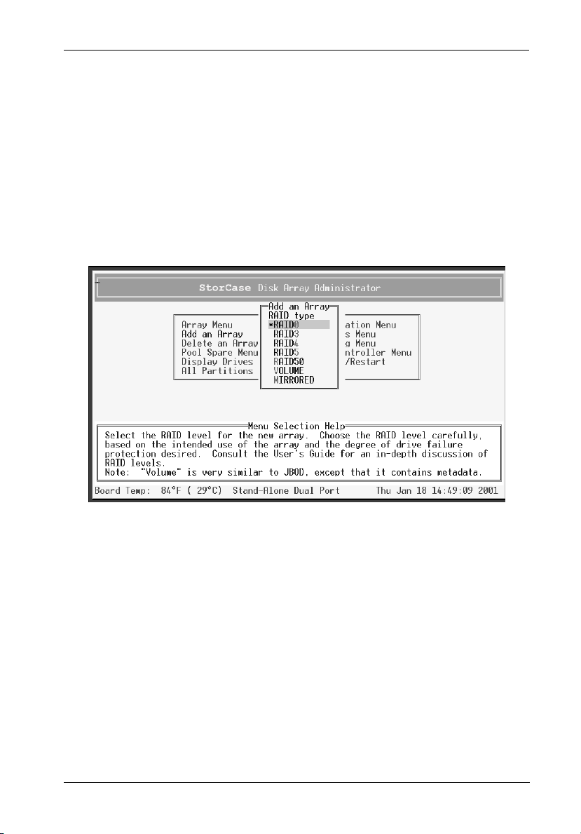
Configuration 31
NOTES: Most UNIX, LINUX, and Macintosh operating systems require the controller
LUN to be a higher value than all array LUNs. Before creating the first array,
change the controller LUN to a higher value or choose NONE (best option)
if not using CAPI to manage the arrays. This allows the first array to be
seen at LUN 0.
The system will now warn you about the LUN for UNIX and Macintosh (see
notes above), the first time an array is created. Press Enter and the
system will ask if you want to be warned again. Select No to avoid receiving this warning again (otherwise, select Yes to be warned the next
time an array is created).
The RAID Type screen should now display (Figure 15).
Figure 15: RAID Type Screen
5. Select the array type (RAID0, RAID3, RAID4, RAID5, RAID50, Volume, or Mirrored)
and press Enter.
NOTES: A RAID 10 array is created when there are more than two (2) drives in a mirrored
FC-SCSI Dual RAID Module User's Guide - Rev. A01 StorCase Technology, Inc.
array.
If RAID 50 is selected as the RAID type, the Select RAID 50 Array Size screen displays
all possible configurations for the array and drive combinations. Select the desired
configuration and press Enter. Skip to Step 7.
For all other RAID types, the Number of Drives screen will display (Figure 16).
Page 45
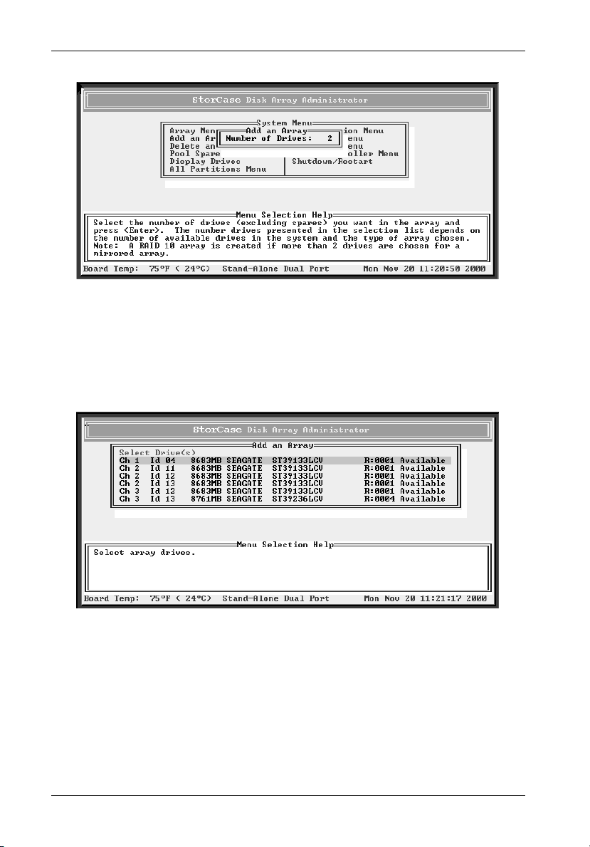
32 Configuration
Figure 16: Number of Drives Screen
6. Enter the number of drives (excluding spares) to be used in the array and press Enter.
The Select Drives screen should now display (Figure 17).
Figure 17: Select Drives Screen
7. Select the drives to be used for the array and press Enter.
A drive is selected by highlighting it and then pressing Enter. Each selected drive turns
gray in the drive list. To skip a drive, use the é or ê key.
If the array is mirrored, RAID 3, RAID 4, RAID 5, or RAID 50 and there are one or more
drives left, the Number of Spares screen will display.
StorCase Technology, Inc. FC-SCSI Dual RAID Module User's Guide - Rev. A01
Page 46
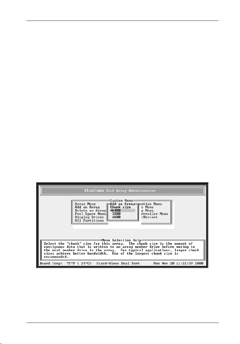
Configuration 33
8. If the Number of Spares screen displays, enter the number of spares to add and press
Enter.
This creates dedicated spares that can only be used in this array. A dedicated spare
drive will not be available for any other use (refer to section "Managing Spares" for
further information).
If no spare is desired, simply enter 0.
The Select Drives screen should now display (Figure 17).
9. Select the drive to be used as a dedicated spare and press Enter.
NOTES: Only available drives (drives that aren't members of an array and are not assigned
as dedicated or pool spares) will be displayed. A drive is selected by highlighting
it and then pressing Enter. Each selected drive turns gray in the drive list. To skip
a drive, use the é or ê key.
A dedicated spare can be deleted from the array at any time (refer to section
"Deleting a Dedicated Spare" for further information).
If the array created is RAID 3, RAID 4, RAID 5, or RAID 50, the Chunk Size screen
will display (Figure 18).
Figure 18: Chunk Size Screen
FC-SCSI Dual RAID Module User's Guide - Rev. A01 StorCase Technology, Inc.
Page 47

34 Configuration
10. Select the chunk size and press Enter.
The chunk size is the amount of contiguous data that is written to an array member
before moving to the next member of the array. To determine the appropriate chunk
size, refer to the operating system's documentation (for example, the default chunk
size for Windows NT and many other operating systems is 64KB).
The system will now confirm your request to create the array.
11. Select the desired option and press Enter.
Offline Initialization - Using this option means the user must wait for the
Online Initialization - Using this option means the user may use the array
The system will now confirm your request to create the array.
12. Select Yes and press Enter.
A message will notify you that the array is being created and will show the progress
of the initialization process. The array initialization process takes from several minutes
to more than an hour depending on the array type (RAID 0, RAID 1, and Volume are
the quickest), array size, drive speed, and other processes running the controller.
array initialization process to finish before using the
array. It uses the zero method to create the array,
which is faster than the verify method.
immediately after creating it, while the array initialization process runs. It uses the verify method to create
the array, which takes longer than the zero method.
Press Esc to return to the Disk Array Administrator Utility and perform other functions.
To check the progress of the array initialization, select Array Menu from the System
Menu. The status of the initialization will display in the list of arrays.
The array initialization process can be stopped (refer to section "Stopping the Array
Initialization Process" for further information).
NOTE: Most operating systems (such as Windows NT 4.0) require the host system to be
StorCase Technology, Inc. FC-SCSI Dual RAID Module User's Guide - Rev. A01
rebooted to see the new array. NetWare v3.45 (and later) can recognize new
devices by typing the command SCAN FOR NEWDEVICES at the console prompt.
Other operating systems might have similar features.
Page 48

Configuration 35
Creating a Multiple-Partition Array
This function allows the user to create multiple-partition arrays. Multiple-partition arrays work
well with very large disk drives and make the most efficient use of disk space for fault tolerance
(parity and spares). Refer to section "Understanding Partitions" for further information.
To create a multiple-partition array:
1. Select Add an Array from the System Menu and press Enter.
The Enter Array Name screen should now display (Figure 13).
2. Enter a name for the array and press Enter.
Up to 20 characters (any character, including spaces) can be used. If no name is to
be used, just press Enter (a name may be added or changed later).
The system will now ask if you want to create one partition for the entire array.
3. Select No to create a multiple-partition array and press Enter.
The RAID Type screen should now display (Figure 15).
4. Select the array type (RAID0, RAID3, RAID4, RAID5, RAID50, VOLUME, or MIRRORED)
and press Enter.
NOTE: A RAID 10 array is created when there are more than two drives in a mirrored array.
If RAID 50 is selected as the RAID type, the Select RAID 50 Array Size screen displays
all possible configurations for the array and drive combinations. Select the desired
configuration and press Enter. Skip to Step 7.
For all other RAID types, the Number of Drives screen will display (Figure 16).
5. Enter the number of drives (excluding spares) to be used in the array and press Enter.
The Select Drives screen should now display (Figure 17).
6. Select the drives to be used for the array and press Enter.
A drive is selected by highlighting it and then pressing Enter. Each selected drive
turns gray in the drive list. To skip a drive, use the é or ê key.
If the array is mirrored, RAID 3, RAID 4, RAID 5, or RAID 50 and there are one or more
drives left, the Number of Spares screen will display.
7. Enter the number of spares to be added and press Enter.
This creates dedicated spares that can only be used in this array. A dedicated spare
drive will not be available for any other use (refer to section "Managing Spares" for
further information).
FC-SCSI Dual RAID Module User's Guide - Rev. A01 StorCase Technology, Inc.
Page 49

36 Configuration
If no spare is desired, simply enter 0.
The Select Drives screen should now display (Figure 17).
8. Select the drive to be used as a dedicated spare and press Enter.
NOTES: Only available drives (drives that aren't members of an array and are not assigned
9. Select the chunk size and press Enter.
10. Select the desired option and press Enter.
11. Select Yes and press Enter.
as dedicated or pool spares) will be displayed. A drive is selected by highlighting
it and then pressing Enter. Each selected drive turns gray in the drive list. To skip
a drive, use the é or ê key.
A dedicated spare can be deleted from the array at any time (refer to section
"Deleting a Dedicated Spare" for further information).
If the array created is RAID 3, RAID 4, RAID 5, or RAID 50, the Chunk Size screen will
display (Figure 15).
The chunk size is the amount of contiguous data that is written to an array member
before moving to the next member of the array. To determine the appropriate chunk
size, refer to the operating system's documentation (for example, the default chunk
size for Windows NT and many other operating systems is 64KB).
The system will now confirm your request to create the array.
Offline Initialization - Using this option means the user must wait for the
array initialization process to finish before using the
array. It uses the zero method to create the array,
which is faster than the verify method.
Online Initialization - Using this option means the user may use the array
immediately after creating it, while the array initialization process runs. It uses the verify method to create
the array, which takes longer than the zero method.
The system will now confirm your request to create the array.
A message will notify you that the array is being created and will show the progress
of the initialization process. The array initialization process takes from several minutes
to more than an hour depending on the array type (RAID 0, RAID 1, and Volume are
the quickest), array size, drive speed, and other processes running the controller.
Press Esc to return to the Disk Array Administrator menus and perform other functions.
To check the progress of the array initialization, select Array Menu from the System
Menu. The status of the initialization will display in the list of arrays.
The array initialization process can be stopped (refer to section "Stopping the Array
Initialization Process" for further information).
StorCase Technology, Inc. FC-SCSI Dual RAID Module User's Guide - Rev. A01
Page 50

Configuration 37
Managing Arrays
The Disk Array Administrator allows the management of arrays, including:
View array and drive status
Stop the initialization process
Add a partition
Verify an array
Reconstruct an array
Expand array capacity
Change array name
Change array ownership
Trust array
Delete array
Viewing Array and Drive Status Information
Array and drive status information is available in two (2) ways:
View array status
View drive status
Viewing Array Status
This function allows the user to view the status of an array, including:
State - Online, Offline, Critical, or Fault-tolerant
Serial Number - A unique number the controller assigns to each array.
Name - The name given to the array.
RAID Level - Array type (0, 3, 4, 5, 50, Volume, or Mirrored). The term "mirrored"
is used for both RAID 1 and RAID 10 arrays.
Number of Drives - The number of drives in the array when fault-tolerant (for
example, if a three drive RAID 5 array was created and one drive is lost, the number
will still show three drives).
FC-SCSI Dual RAID Module User's Guide - Rev. A01 StorCase Technology, Inc.
Page 51

38 Configuration
Number of Drives per Subarray - (for RAID 50 only) The number of drives in each
underlying RAID 5 array.
Number of Spare Drives - The number of spare drives dedicated to the array.
Size - The size of the entire array (expressed in MB or GB for arrays larger than
10GB).
Chunk Size - The array's chunk size.
Date Created - The date the array was created.
Utility - The utility running (None, Verify, Reconstruct, Expand, or Initialize).
Number or Partitions - The number of partitions created on the array.
Free Partition Total - The amount of free space (no partition) on the array.
To view the status of an array:
1. Select Array Menu from the System Menu and press Enter.
The Select Array screen should now display, along with a list of existing arrays (Figure
19).
Figure 19: Select Array Screen
StorCase Technology, Inc. FC-SCSI Dual RAID Module User's Guide - Rev. A01
Page 52

Configuration 39
2. Select the array to be viewed and press Enter.
The Array Menu should now display (Figure 20).
Figure 20: Array Menu Screen
3. Select Array Status and press Enter.
The Array Status screen should now display, showing the status of the array selected
(Figure 21).
Figure 21: Array Status Screen
4. Press Esc to return to the Array Menu.
FC-SCSI Dual RAID Module User's Guide - Rev. A01 StorCase Technology, Inc.
Page 53

40 Configuration
Viewing Drive Status
This function allows the user to view the status of the drives in an array, including:
Drive Number - The drive's sequential position in the controller's drive list.
Drive Status - Indicates the condition of the drive (whether it is up or down).
Channel Number - Back-end disk bus number.
Target ID
Size - Size of the drive in MB.
Status - Indicates the array name and member number (if drive is part of an array).
If the drive is not part of an array, it will indicate status as "Available". If the drive
was part of an array that no longer exists, it will indicate status as "Leftover".
NOTE: The drive may not be listed if it has failed or malfunctioned.
To view the status of a drive:
1. Select Array Menu from the System Menu and press Enter.
The Select Array screen should now display, along with a list of existing arrays (Figure
19).
2. Select the desired array and press Enter.
The Array Menu should now display (Figure 20).
3. Select Drive Status and press Enter.
The Drive Status screen should now display, showing all drives that are members of
the array as well as those assigned as dedicated spares (Figure 22).
StorCase Technology, Inc. FC-SCSI Dual RAID Module User's Guide - Rev. A01
Page 54

Configuration 41
Figure 22: Drive Status Screen
Use the é o r ê key to scroll through the drives. These are the drives that are currently
members of the array.
4. Press Esc to return to the Array Menu.
Stopping the Array Initialization Process
This function allows the user to stop the initialization process during an array initialization.
After the process is stopped, the array is marked as offline and cannot be used. The drives
will remain array members and the array must be deleted before the drives can be used again.
To stop the initialization process:
1. Select Array Menu from the System Menu and press Enter.
The Select Array screen should now display, along with a list of existing arrays (Figure
19).
2. Select the array to be stopped and press Enter.
The Array Menu should now display (Figure 20).
3. Select Abort Initialization and press Enter.
FC-SCSI Dual RAID Module User's Guide - Rev. A01 StorCase Technology, Inc.
Page 55

42 Configuration
The system will now confirm your request to stop the initialization process.
4. Select Yes and press Enter.
Adding a Partition
In order to create a multiple-partition array, at least one partition on the array must be created
before the array can be used. Partitions on a multiple-partition array can be created as long
as there is free space (refer to section "Understanding Partitions" for further information).
To add a partition:
1. Select Array Menu from the System Menu and press Enter.
The Select Array screen should now display, along with a list of existing arrays (Figure
19).
2. Select the desired multiple-partition array and press Enter.
The Array Menu should now display (Figure 20).
3. Select Add a Partition and press Enter.
The Select Free Partition screen should now display, along with a list of free partitions
(Figure 23).
A free partition is free space that has not yet been partitioned, or space that used to
have a partition (before it was deleted).
Figure 23: Select Free Partition Screen
StorCase Technology, Inc. FC-SCSI Dual RAID Module User's Guide - Rev. A01
Page 56

Configuration 43
4. Select the free partition desired and press Enter.
The Partition Size screen should now display (Figure 24).
Figure 24: Partition Size Screen
5. Enter the desired partition size and press Enter.
The Partition Name screen should now display (Figure 25).
Figure 25: Partition Name Screen
FC-SCSI Dual RAID Module User's Guide - Rev. A01 StorCase Technology, Inc.
Page 57
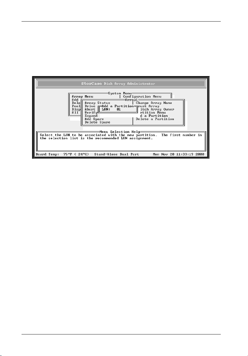
44 Configuration
6. Enter a name for the partition and press Enter.
Up to 20 characters (any character, including spaces) can be used. If no name is to
be used, just press Enter (a name may be added or changed later).
The Partition LUN screen should now display (Figure 26).
Figure 26: Partition LUN Screen
7. Select the LUN for the partition and press Enter.
The LUN displayed is the suggested default LUN assignment.
If the letters OV appear before a LUN, this indicates that the selection overlaps with
a soft LUN, most likely the controller or SAF-TE Environmental Processor (SEP) LUN.
An array at an overlapped LUN may be created, but it will not be seen by the host
system until the controller is rebooted.
NOTE: Most UNIX, LINUX, and Macintosh operating systems require the controller LUN to
8. Select Yes and press Enter.
StorCase Technology, Inc. FC-SCSI Dual RAID Module User's Guide - Rev. A01
be a higher value than all array LUNs. Before creating the first array, change the
controller LUN to a higher value or choose NONE (best option) if not using CAPI to
manage the arrays. This allows the first array to be seen at LUN 0.
The system will now confirm the change.
Page 58

Configuration 45
Verifying an Array
This function allows the user to verify data on a specified array (RAID 3, RAID 4, RAID 5, RAID
50, and Mirrored arrays only).
RAID 3, RAID 4, RAID 5, and RAID 50 - Verifies all parity blocks in the selected array
and corrects any bad parity.
Mirrored - Compares the primary and secondary drives. If a mismatch occurs, the
primary is copied to the secondary.
Verify an array whenever a problem is suspected.
To verify an array:
1. Select Array Menu from the System Menu and press Enter.
The Select Array screen should now display, along with a list of existing arrays (Figure
19).
2. Select the array to verify and press Enter.
The Array Menu should now display (Figure 20).
3. Select Verify Function and press Enter.
The Verify Menu should now display (Figure 27).
Figure 27: Verify Menu Screen
4. Select Start Verify and press Enter.
FC-SCSI Dual RAID Module User's Guide - Rev. A01 StorCase Technology, Inc.
Page 59

46 Configuration
Verification will begin and the percentage of verification will now be displayed. The
array can be used during the verification process.
5. Press Esc to return to the Verify Menu.
Viewing Verification Status
This function allows the user to view the status of the verification process while it is running.
To view verification status:
1. Select Array Menu from the System Menu and press Enter.
The Select Array screen should now display, along with a list of existing arrays (Figure
19).
2. Select the array to view and press Enter.
The Array Menu should now display (Figure 20).
3. Select Verify Function and press Enter.
The Verify Menu should now display (Figure 27).
4. Select View Verify Status and press Enter.
The Verify Status screen should now display (Figure 28).
Figure 28: Verify Status Screen
5. Press Esc to return to the Verification Menu.
StorCase Technology, Inc. FC-SCSI Dual RAID Module User's Guide - Rev. A01
Page 60

Configuration 47
Stopping the Verification
This function allows the user to stop the verification process. Normally, it is best to let the
verification process finish, although stopping the verification does not cause any damage to
the data.
To stop the verification process:
1. Select Array Menu from the System Menu and press Enter.
The Select Array screen should now display, along with a list of existing arrays (Figure
19).
2. Select the desired array and press Enter.
The Array Menu should now display (Figure 20).
3. Select Verify Function and press Enter.
The Verify Menu should now display (Figure 27).
4. Select Abort Verify and press Enter.
The system will now confirm your request to stop the verification process.
5. Select Yes and press Enter.
Reconstructing an Array
The controller automatically reconstructs redundant arrays (RAID 3, RAID 4, RAID 5, RAID 50,
and Mirrored) if an array becomes critical and if a spare drive (with enough space) is available.
An array becomes critical when one or more member drives fail.
If a reconstruct does not start automatically, it is because there are no valid spares available.
To start a reconstruct, replace the failed drive and add it as a spare (refer to sections "Adding
a Dedicated Spare" and "Enabling Dynamic Spares" for further information).
NOTE: Any pool spares added may be used by any critical array, and not necessarily by
FC-SCSI Dual RAID Module User's Guide - Rev. A01 StorCase Technology, Inc.
the intended array.
Page 61

48 Configuration
Expanding Array Capacity (OCE)
Online Capacity Expansion (OCE) allows the user to expand the arrays without having to stop
I/O activity. Only one array can be expanded at a time, and the expansion of the array must
be completed before expanding another array.
NOTES: Expanding an array does not change the size of the host operating system partitions
that reside on the array (the controller only works at the block level, not at the file
system level of the operating system). To use the new space, a new partition must
be created (using the newly added space) or a third-party application (specific to
the operating system) must be used to change the partition size.
The OCE function may take an hour or more to complete, depending on the array type,
array size, drive speed, and other processes running the controller.
Once an OCE has started, it cannot be aborted!
The number of drives that can be added to an array depends upon the RAID level.
Table 6: OCE Drive Additions by RAID Level
RAID Level # of Drives that can be Added
RAID 0
RAID 1
RAID 3, 4, or 5
RAID 10
RAID 50 3-5
Volume Set
1-4
Does not support OCE
1-4
2 or 4
Does not support OCE
Max. # of Drives
15
N/A
15
15
30
N/A
IFSII_FDR16
To expand multiple-partition arrays, free space is added at the end of the array (refer to section
"Understanding Partitions" for further information).
StorCase Technology, Inc. FC-SCSI Dual RAID Module User's Guide - Rev. A01
Page 62

Configuration 49
To expand an array:
1. Select Array Menu from the System Menu and press Enter.
The Select Array screen should now display, along with a list of existing arrays (Figure
19).
2. Select the array to expand and press Enter.
The Array Menu should now display (Figure 20).
3. Select Expand Function and press Enter.
The Expand Menu should now display.
4. Select Start Expand and press Enter.
The Number of Drives screen should now display (Figure 29).
Figure 29: Expand Function Screen
5. Enter the number of drives to be added and press Enter.
The Select Drives screen should now display (Figure 30).
FC-SCSI Dual RAID Module User's Guide - Rev. A01 StorCase Technology, Inc.
Page 63

50 Configuration
Figure 30: Select Drives to Expand Screen
6. Select the drives to be added (from the list of available drives) and press Enter.
Expansion will begin and the percentage of expansion will now display.
NOTE: Only available drives (drives that aren't members of an array and are not assigned
7. Press Esc to return to the Array Menu.
StorCase Technology, Inc. FC-SCSI Dual RAID Module User's Guide - Rev. A01
as dedicated or pool spares) will be displayed. A drive is selected by highlighting
it and then pressing Enter. Each selected drive turns gray in the drive list. To skip
a drive, use the é or ê key.
Page 64

Configuration 51
Viewing Expand Status
This function allows the user to view the status of the expansion process while it is running.
To view expand status:
1. Select Array Menu from the System Menu and press Enter.
The Select Array screen should now display, along with a list of existing arrays (Figure
19).
2. Select the array to view and press Enter.
The Array Menu should now display (Figure 20).
3. Select Expand Function and press Enter.
The Expand Menu should now display.
4. Select View Expand Status and press Enter.
The Expand Status screen should now display.
5. Press Esc to return to the Expand Menu.
Changing an Array Name
This function allows the user to change the name of an array. This does not affect the target
ID or LUN values of an array. The controller will not allow an array name to be changed while
a utility is running.
To change an array name:
1. Select Array Menu from the System Menu and press Enter.
The Select Array screen should now display, along with a list of existing arrays (Figure
19).
2. Select the array to view and press Enter.
The Array Menu should now display (Figure 20).
3. Select Change Array Name and press Enter.
The Enter New Name screen should now display.
FC-SCSI Dual RAID Module User's Guide - Rev. A01 StorCase Technology, Inc.
Page 65

52 Configuration
4. Enter a name for the array and press Enter.
Up to 20 characters (any character, including spaces) can be used.
The system will now confirm the change.
5. Select Yes and press Enter.
Changing Array Ownership
If using the Active-Active mode, this function allows the user to change the ownership of any
array between the controllers.
Changing ownership lets the user continue using an array without interruption and makes the
array visisble on the controller the user changes it to (the user will no longer see the array
ion the original controller).
To change array ownership:
1. Select Array Menu from the System Menu and press Enter.
The Select Array screen should now display, along with a list of existing arrays (Figure
19).
2. Select the desired array and press Enter.
The Array Menu should now display (Figure 20).
3. Select Switch Array Owner and press Enter.
The system will now confirm your request to change ownership.
4. Select Yes and press Enter.
5. Assign a new LUN to each array partition.
StorCase Technology, Inc. FC-SCSI Dual RAID Module User's Guide - Rev. A01
Page 66

Configuration 53
Trusting an Array
This function allows the user to bring an array back online by resynchronizing the time/date
stamp and any other metadata on a bad disk. This will make the disk an active member of the
array again. Use this function whenever:
One or more disks of an array start up more slowly or were powered ON after the
rest of the disks in the array. This will cause the time/date stamps to differ, which
the controller will interpret as a problem with the "late" disks. In such a case, the
array will function normally after using the Trust Array function.
An array is offline because a drive is failing, there is no data backup, and the user
is attempting to recover data from the array. In such a case, the Trust Array function
may work but only as long as the failing drive continues to operate.
Before using this function, it must be enabled in the Option Configuration Menu (default setting
is DISABLED).
CAUTION: The Trust Array function can cause unstable operation and data loss if
To trust an array:
1. Select Configuration Menu from the System Menu and press Enter.
The Configuration Menu should now display (Figure 31).
used improperly! This feature is intended for disaster recovery only!
Figure 31: Configuration Menu Screen
FC-SCSI Dual RAID Module User's Guide - Rev. A01 StorCase Technology, Inc.
Page 67

54 Configuration
2. Select Option Configuration and press Enter.
The Option Configuration Menu should now display (Figure 32).
Figure 32: Option Configuration Screen
3. Select Enable Trust Array and press Enter.
The Enable Trust Array screen should now display.
4. Select Enable and press Enter.
NOTE: The Enable Trust Array option is only enabled until it is used. Once the Trust Array
StorCase Technology, Inc. FC-SCSI Dual RAID Module User's Guide - Rev. A01
option is used for an array, the option is automatically disabled.
Page 68

Configuration 55
5. Press Esc twice to return to the System Menu.
6. Select Array Menu from the System Menu and press Enter.
The Select Array screen should now display, along with a list of existing arrays (Figure
19).
7. Select the desired array and press Enter.
The Array Menu should now display (Figure 20).
8. Select Trust Array and press Enter.
The system will now confirm your request to trust the array.
9. Select Yes and press Enter.
NOTE: If the array does not come back online, it may be because there are too many members
offline. Or, it may be because the array may have additional failures on the bus (or
enclosure) that the Trust Array option cannot fix.
Deleting an Array
This function allows the user to delete an array when the array is no longer needed or when
the drives are needed for another use.
CAUTION: Deleting an array will delete all partitions and data stored in that array!
NOTE: An array cannot be deleted while any utility (Initialize, Verify, Expand, or Reconstruct)
is running on the array. The utility must be stopped (if possible) or completed before
the array can be deleted.
To delete an array:
1. Select Delete an Array from the System Menu and press Enter.
The Select Array screen should now display (Figure 19).
2. Select the array to be deleted and press Enter.
The system will now confirm your request to delete the array.
3. Select Yes and press Enter.
Before reusing the drives, performing a low-level format on each drive is
recommended.
FC-SCSI Dual RAID Module User's Guide - Rev. A01 StorCase Technology, Inc.
Page 69

56 Configuration
Managing Partitions
The Disk Array Administrator software allows the user to manage partitions, including:
View partition status information
Add a partition
Expand a partition
Change a partition name
Change a partition LUN
Delete a partition
Understanding Partitions
When an array is created, the array can either be all one partition or it can be set up with multiplepartitions. Using multiple-partitions, allows the user to create one very large array (making
efficient use of the drives). For example, one very large RAID 5 array can be created with
one dedicated spare assigned to the array. This minimizes the amount of disk space allocated
to parity and spares (compared to the disk space required for 5-6 smaller RAID 5 arrays).
Once an array is set up for multiple-partitions, the user must create each partition by setting
the partition size and assigning the partition a LUN. It is recommended that each partition be
assigned a name that will indicate how each partition will be used (for example, if the first
partition is used to store a customer database, name it "cust data base").
When a multiple-partition array is first created, all the space on the array is designated as free
space (Figure 33).
Free Space
IFS_76
Figure 33: Array Set-up for Partitions Before Creating Partitions
StorCase Technology, Inc. FC-SCSI Dual RAID Module User's Guide - Rev. A01
Page 70

Configuration 57
When a partition is created, the user must specify the size (in MB) of the partition (Figure 34).
Partition 1
Free Space
IFS_77
Figure 34: Array after Creating One Partition
The Disk Array Administrator assigns each partition a unique serial number and sequence
number. Sequence numbers are assigned in the order the partitions are created. Once one
or more partitions are created on an array, additional partitions may be created in the remaining
free space or a partition may be expanded (with some limitations).
A partition can only be expanded into contiguous, free space following the partition.
After all of the free space has been partitioned, the partition can only be expanded by deleting
a partition that follows (the next highest in sequence) the partition to be expanded. In Figure
35, partition 3 can be deleted so that partition 2 can be expanded to use some or all of partition
3's space.
CAUTION: Deleting a partition also deletes all data stored in that partition! Be sure to
back up all data before deleting a partition!
Partition 1 Partition 2 Partition 3 Partition 4 Partition 5
IFS_78
Figure 35: Array after Creating Five Partitions
When expanding an array, free space is added at the end of the array as shown in Figure 36
(refer to section "Expanding Array Capacity" for further information).
FC-SCSI Dual RAID Module User's Guide - Rev. A01 StorCase Technology, Inc.
Page 71

58 Configuration
Partition 1 Partition 2 Partition 3 Partition 4 Partition 5 Free Space
IFS_79
Figure 36: Array (with Five Partitions) after Expansion
After an array is expanded, the user can either add a partition or expand the last partition to
utilize the free space. One or more partitions can also be deleted to expand the last partition.
Viewing Partition Status Information
The user can perform three functions related to partition status information:
View Partition Status
View Partition Statistics
Reset Partition Statistics
Viewing Partition Status
This function allows the user to view the status the partition, including the following:
Array State - Online, Offline, Critical, or Fault-tolerant
Array Type - RAID level (0, 3, 4, 5, 50, Volume, or Mirrored). The term "mirrored"
is used for both RAID 1 and RAID 10 arrays.
Array Drives - Number of drives in the array when fault-tolerant (for example, if
a three drive RAID 5 array was created and one drive is lost, the number will still
show three drives).
Name - The name of the partition.
Serial Number - Target ID: LUN - Target ID and LUN presented to the host system.
Partition Size - Size of the partition (in MB).
Percentage of Total Array - The percentage of the total array that this partition
represents.
Write-back Caching - Status of the write-back cache (enabled or disabled) for
this array.
StorCase Technology, Inc. FC-SCSI Dual RAID Module User's Guide - Rev. A01
Page 72

Configuration 59
To view the status of a partition:
1. Display the Partition Menu.
From the Array Menu From the All Partitions Menu
1. Select Array Menu from the
System Menu and press Enter.
The Select Array screen should now display, along with a
list of existing arrays.
2. Select the desired array and
press Enter.
The Array Menu screen should now display.
3. Select Partition Menu and press
Enter.
The Select Partition screen should now display along with a
list of exisiting partitions for the selected array.
4. Select the partition to be viewed
and press Enter.
The Partition Menu screen should now display.
1. Select All Partitions Menu from the
System Menu and press Enter.
The Select Partition or Free Area screen should now display,
along with a list of existing partitions and free space.
2. Select the desired partition and
press Enter.
The Partition Menu screen should now display.
IFSII_FDR17
The Partition Menu should now display (Figure 37).
Figure 37: Partition Menu Screen
FC-SCSI Dual RAID Module User's Guide - Rev. A01 StorCase Technology, Inc.
Page 73
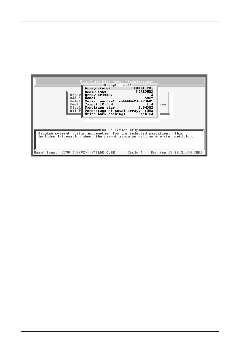
60 Configuration
2. Select Partition Status and press Enter.
The Partition Status screen should now display (Figure 38).
3. Press Esc to return to the Partition Menu.
Figure 38: Partition Status Screen
Viewing Partition Statistics
This function allows the user to view the statistics of the partition, including the following:
Read - Total number of host read requests directed to the partition.
Write - Total number of host write requests directed to the partition.
SecRd - Total number of sectors read from the partition.
SecWt - Total number of sectors written to the partition.
Queue Depth - Current number of queued up commands from the host.
I/O Size - Last host I/O block size request (in 512-byte sectors).
Similar statistics are also available on an aggregate basis for all partition LUNs (refer to section
"Displaying Overall Statistics" for further information).
StorCase Technology, Inc. FC-SCSI Dual RAID Module User's Guide - Rev. A01
Page 74

Configuration 61
To view the statistics of a partition:
1. Display the Partition Menu.
From the Array Menu From the All Partitions Menu
1. Select Array Menu from the
System Menu and press Enter.
The Select Array screen should now display, along with a
list of existing arrays.
2. Select the desired array and
press Enter.
The Array Menu screen should now display.
3. Select Partition Menu and press
Enter.
The Select Partition screen should now display along with a
list of exisiting partitions for the selected array.
4. Select the partition to be viewed
and press Enter.
The Partition Menu screen should now display.
1. Select All Partitions Menu from the
System Menu and press Enter.
The Select Partition or Free Area screen should now display,
along with a list of existing partitions and free space.
2. Select the desired partition and
press Enter.
The Partition Menu screen should now display.
IFSII_FDR17
The Partition Menu should now display (Figure 37).
2. Select Partition Statistics and press Enter.
The Partition Statistics Menu should now display (Figure 39).
FC-SCSI Dual RAID Module User's Guide - Rev. A01 StorCase Technology, Inc.
Page 75

62 Configuration
Figure 39: Partition Statistics Menu Screen
3. Select View Statistics and press Enter.
The Partition Statistics screen should now display (Figure 40).
4. Press Esc to return to the Statistics Menu.
Figure 40: Partition Statistics Screen
StorCase Technology, Inc. FC-SCSI Dual RAID Module User's Guide - Rev. A01
Page 76
Configuration 63
Resetting Partition Statistics
This function allows the user to reset the following partition statistics to zero:
Read
Write
SecRd
SecWt
I/O Size
NOTES: Resetting statistics also resets the statistics for this partition that are included in the
total overall statistics (refer to section "Displaying Overall Statistics" for further
information).
Queue depth vaule cannot be reset. It will always reflect the current I/O queue depth.
You may want to reset the statistics after monitoring performance, benchmark testing, or after
a change in how the partition is used.
To reset partition statistics:
1. Display the Partition Menu.
From the Array Menu From the All Partitions Menu
1. Select Array Menu from the
System Menu and press Enter.
The Select Array screen should now display, along with a
list of existing arrays.
2. Select the desired array and
press Enter.
The Array Menu screen should now display.
3. Select Partition Menu and press
Enter.
The Select Partition screen should now display along with a
list of exisiting partitions for the selected array.
4. Select the partition to be viewed
and press Enter.
The Partition Menu screen should now display.
1. Select All Partitions Menu from the
System Menu and press Enter.
The Select Partition or Free Area screen should now display,
along with a list of existing partitions and free space.
2. Select the desired partition and
press Enter.
The Partition Menu screen should now display.
IFSII_FDR17
The Partition Menu should now display (Figure 37).
FC-SCSI Dual RAID Module User's Guide - Rev. A01 StorCase Technology, Inc.
Page 77

64 Configuration
2. Select Partition Statistics and press Enter.
The Partition Statistics Menu should now display (Figure 40).
3. Select Reset Statistics and press Enter.
The system will now confirm your request to reset the statistics.
4. Select Yes and press Enter.
Expanding a Partition
This function allows the user to expand an existing partition (with some limitations). A partition
can only be expanded into contiguous, free space following the partition (refer to section
"Understanding Partitions" for further information).
To expand a partition:
1. Display the Partition Menu.
From the Array Menu From the All Partitions Menu
1. Select Array Menu from the
System Menu and press Enter.
The Select Array screen should now display, along with a
list of existing arrays.
2. Select the desired array and
press Enter.
The Array Menu screen should now display.
3. Select Partition Menu and press
Enter.
The Select Partition screen should now display along with a
list of exisiting partitions for the selected array.
4. Select the partition to be viewed
and press Enter.
The Partition Menu screen should now display.
1. Select All Partitions Menu from the
System Menu and press Enter.
The Select Partition or Free Area screen should now display,
along with a list of existing partitions and free space.
2. Select the desired partition and
press Enter.
The Partition Menu screen should now display.
IFSII_FDR17
The Partition Menu should now display (Figure 37).
StorCase Technology, Inc. FC-SCSI Dual RAID Module User's Guide - Rev. A01
Page 78

Configuration 65
2. Select Expand Partition and press Enter.
The Expand Partition screen should now display (Figure 41).
Figure 41: Expand Partition Screen
3. Enter the desired size and press Enter.
The system will now confirm your request to expand the partition.
4. Select Yes and press Enter.
FC-SCSI Dual RAID Module User's Guide - Rev. A01 StorCase Technology, Inc.
Page 79

66 Configuration
Changing a Partition Name
This function allows the user to change the name of a partition. This does not affect the Target
ID or LUN values of the partition. The controller does not allow the partition name to be changed
while a utility is running.
To change a partition name:
1. Display the Partition Menu.
From the Array Menu From the All Partitions Menu
1. Select Array Menu from the
System Menu and press Enter.
The Select Array screen should now display, along with a
list of existing arrays.
2. Select the desired array and
press Enter.
The Array Menu screen should now display.
3. Select Partition Menu and press
Enter.
The Select Partition screen should now display along with a
list of exisiting partitions for the selected array.
4. Select the partition to be viewed
and press Enter.
The Partition Menu screen should now display.
1. Select All Partitions Menu from the
System Menu and press Enter.
The Select Partition or Free Area screen should now display,
along with a list of existing partitions and free space.
2. Select the desired partition and
press Enter.
The Partition Menu screen should now display.
IFSII_FDR17
The Partition Menu should now display (Figure 37).
2. Select Change Partition Name and press Enter.
The Enter New Name screen should now display.
3. Enter the new name and press Enter.
Up to 20 characters (any character, including spaces) can be used.
The system will now confirm your request to change the partition name.
4. Select Yes and press Enter.
StorCase Technology, Inc. FC-SCSI Dual RAID Module User's Guide - Rev. A01
Page 80

Configuration 67
Changing a Partition LUN
This function allows the user to change the LUN assigned to a partition, as it appears under
the controller's Target ID. The change is immediate, although the host system may need to be
rebooted for the partition to reflect the new LUN (refer to section "Understanding LUNs and
Viewing LUN Information" for further information).
NOTE: The partition LUN cannot be changed to a LUN that is already in use (the LUN must
be reassigned before it can be used).
To change a partition LUN:
1. Display the Partition Menu.
From the Array Menu From the All Partitions Menu
1. Select Array Menu from the
System Menu and press Enter.
The Select Array screen should now display, along with a
list of existing arrays.
2. Select the desired array and
press Enter.
The Array Menu screen should now display.
3. Select Partition Menu and press
Enter.
The Select Partition screen should now display along with a
list of exisiting partitions for the selected array.
4. Select the partition to be viewed
and press Enter.
The Partition Menu screen should now display.
1. Select All Partitions Menu from the
System Menu and press Enter.
The Select Partition or Free Area screen should now display,
along with a list of existing partitions and free space.
2. Select the desired partition and
press Enter.
The Partition Menu screen should now display.
IFSII_FDR17
The Partition Menu should now display (Figure 37).
2. Select Change LUN and press Enter.
The New LUN screen should now display.
3. Enter the new LUN and press Enter.
The system will now confirm your request to change the partition LUN.
4. Select Yes and press Enter.
FC-SCSI Dual RAID Module User's Guide - Rev. A01 StorCase Technology, Inc.
Page 81

68 Configuration
Deleting a Partition
This function allows the user to delete a partition.
CAUTION: Deleting a partition also deletes all data stored in that partition! Be sure to
back up all data before deleting a partition!
NOTES: A partition cannot be deleted while any utility (Initialize, Verify, Expand, or Reconstruct)
is running on the array. The utility must be stopped (if allowed) or completed before
the partition can be deleted.
There is also a Delete Partition option available in the Array Menu.
To delete a partition:
1. Display the Partition Menu.
From the Array Menu From the All Partitions Menu
1. Select Array Menu from the
System Menu and press Enter.
The Select Array screen should now display, along with a
list of existing arrays.
2. Select the desired array and
press Enter.
The Array Menu screen should now display.
3. Select Partition Menu and press
Enter.
The Select Partition screen should now display along with a
list of exisiting partitions for the selected array.
4. Select the partition to be viewed
and press Enter.
The Partition Menu screen should now display.
1. Select All Partitions Menu from the
System Menu and press Enter.
The Select Partition or Free Area screen should now display,
along with a list of existing partitions and free space.
2. Select the desired partition and
press Enter.
The Partition Menu screen should now display.
IFSII_FDR17
The Partition Menu should now display (Figure 37).
2. Select Delete this Partition and press Enter.
The system will now confirm your request to delete the partition.
3. Select Yes and press Enter.
StorCase Technology, Inc. FC-SCSI Dual RAID Module User's Guide - Rev. A01
Page 82

Configuration 69
Monitoring System Status
The user should monitor the system regularly to ensure that the controller, disks, and arrays
are working properly. The Disk Array Administrator allows the user to monitor the system,
including the following:
Event Log
Hardware Information
Array Status Screen
Disk Status Screen
Power ON Self-Test (POST)
Overall Statistics Screen
Displaying the Event Log
The controller's event log contains important information regarding the status of the controller,
disks, and arrays. The user should check the log regularly to monitor the status of the system
Refer to sections "Warning and Error Events" (regarding specific warning and error events)
and "Understanding SCSI Errors" (regarding specific SCSI disk and channel errors) for further
information.
Below is a list of some of the key warning and failure events included in the Event Log during
operation:
Disk detected error
Disk channel error
Battery failure
Drive down
Power up
Array critical
Array offline
Temperature warning
Temperature failure (will lead to a shutdown, which is logged)
Voltage warning
Voltage failure (will lead to a shutdown, which is logged)
FC-SCSI Dual RAID Module User's Guide - Rev. A01 StorCase Technology, Inc.
Page 83

70 Configuration
The event log will store the most recent 400 events. Events are numbered sequentially from
001-999. The event number resets to 001 after 999 events have been logged.
NOTE: If there is a problem with the controller or an array, check the event log before calling
The event information can be viewed in three (3) ways:
The user can also capture the event log to a file (refer to section "Capturing the Event Log
File" for further information).
technical support. Event log messages can help resolve the problem without having
to call technical support. Refer to section "Troubleshooting" for further information.
Most recent event
One event at a time (most recent event first)
Full screen of events
Viewing the Most Recent Event
The most recent voltage or temperature event will display in rotation with the date and time
(whenever the Disk Array Administrator times out and returns to its initial screen).
Viewing One Event at a Time
This function allows the user to view controller-related events one at a time. The most recent
event will be displayed first.
To view one event at a time:
1. Select Event Log Menu from the System Menu and press Enter.
The Event Log Menu should now display (Figure 42).
StorCase Technology, Inc. FC-SCSI Dual RAID Module User's Guide - Rev. A01
Page 84

Configuration 71
Figure 42: Event Log Menu Screen
2. Select View Event Log and press Enter.
The Event Log screen should now display the last event that occurred (Figure 43).
Event Date
Event
Array Serial
Number
Figure 43: Event Log Screen
3. Press é to view the previous event.
Press é to continue viewing previous events.
4. Press Esc to return to the Event Log Menu.
FC-SCSI Dual RAID Module User's Guide - Rev. A01 StorCase Technology, Inc.
Event Time
Event Type (Blank
is an information
event, a W is a
warning event, an
E is an error event)
Page 85

72 Configuration
Viewing a Whole Screen of Events
This function allows the user to view events from the log file a whole screen at a time. This
allows the user to review all recent events quickly (the events will display in chronological
order, the most recent event being last in the list).
To view a whole screen of events:
1. Press CTRL-E from anywhere in the Disk Array Administrator Utility.
The first screen of events should now display (Figure 44).
Figure 44: Whole Screen of Events
Third column shows event type:
"Blank" = Information event
W= Warning event
E = Error event
2. Press U to page up or D to page down in the log.
3. Press CTRL-E to page through the other information screens and to return to the menu.
StorCase Technology, Inc. FC-SCSI Dual RAID Module User's Guide - Rev. A01
Page 86

Configuration 73
Capturing the Event Log File
This function allows the user to capture the entire event log (which is saved as a file on the
user's hard drive). This allows the user to print the log or even attach it to an email.
The steps below are for HyperTerminal. The procedure may differ for different terminal emulators.
To capture the event log file:
1. With HyperTerminal running, press CTRL-E until the Event Log displays.
2. Select Capture Text from the Transfer Menu (in HyperTerminal).
The Capture Text screen should now display.
3. Enter the desired path and file name to store the log file contents.
4. Click Start.
5. Press P (on the keyboard) to begin the transfer.
6. Select Capture Text from the Transfer Menu (in HyperTerminal).
The Capture Text screen should now display.
7. Click Stop.
FC-SCSI Dual RAID Module User's Guide - Rev. A01 StorCase Technology, Inc.
Page 87
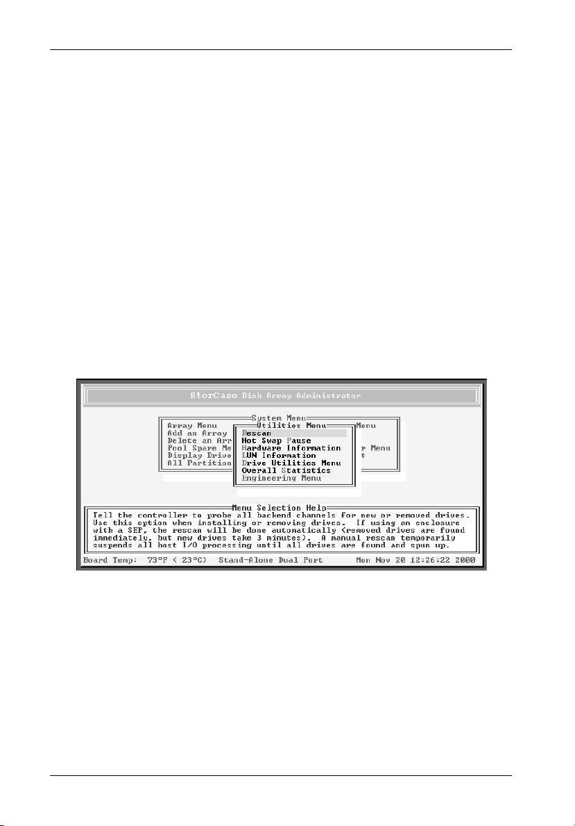
74 Configuration
Displaying Hardware and Configuration Information
This function allows the user to display the controller's hardware and configuration information. For example, the firmware version can be found here (technical support may request
this information when troubleshooting).
The hardware and configuration information can be displayed in two (2) ways:
Hardware information only
Hardware and configuration information
To view hardware information only:
1. Select Utilities Menu from the System Menu and press Enter.
The Utilities Menu should now display (Figure 45).
Figure 45: Utilities Menu Screen
2. Select Hardware Information and press Enter.
The Hardware Information screen should now display (Figure 46).
StorCase Technology, Inc. FC-SCSI Dual RAID Module User's Guide - Rev. A01
Page 88
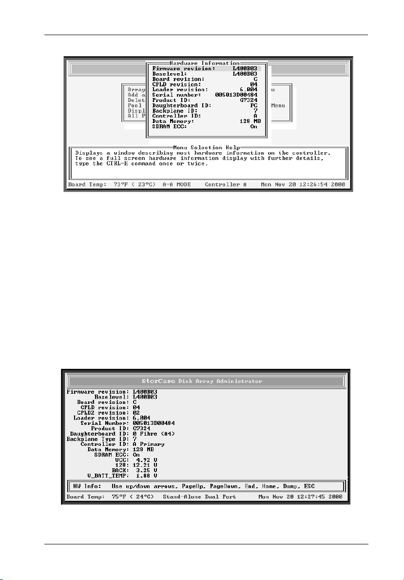
Configuration 75
Figure 46: Hardware Information Screen
3. Press Esc to return to the Utilities Menu.
To view hardware and configuration information:
1. Press CTRL-E from anywhere in the Disk Array Administrator Utility.
The first screen of events should now display (Figure 44).
2. Press CTRL-E again.
The HW Info screen should now display (Figure 47).
Figure 47: HW Info Screen
FC-SCSI Dual RAID Module User's Guide - Rev. A01 StorCase Technology, Inc.
Page 89

76 Configuration
3. Press CTRL-E again.
Press Esc to return to the previous screen.
The CFG Info screen should now display (Figure 48).
Figure 48: CFG Info Screen
4. Press CTRL-E or ESC to return.
Displaying Overall Statistics
This function allows the user to view two (2) types of aggregate statistics for all partition LUNs:
General statistics - (Similar statistics are also available for individual partition LUNs.
- I/O operations per second (IOPS)
- Bandwidth (in MBytes/second)
- Number of read operations
- Number of write operations
- Total sectors written
- Total current command queue depth across all LUNs
StorCase Technology, Inc. FC-SCSI Dual RAID Module User's Guide - Rev. A01
Refer to section "Viewing Partition Statistics" for further information.)
Page 90

Configuration 77
Host read/write histogram - shows how many host reads and writes fall into a
- 1 Sector
- 2-3 Sectors
- 4-7 Sectors
- 8-15 Sectors
- 16-31 Sectors
- 32-63 Sectors
- 64-127 Sectors
- 128-255 Sectors
- 256-511 Sectors
- 512-1023 Sectors
- 1024-2047 Sectors
- 2048 (and up) Sectors
This information may be helpful in interpreting performance based on individual system
configurations and operating systems. The information displayed here can be useful in profiling
applications and their usage of the partition, and determining what type of RAID level is
applicable to the user's needs.
particular size range (I/O ranges are based on powers of two).
NOTE: The statistics are provided as general information. They are not intended for bench-
FC-SCSI Dual RAID Module User's Guide - Rev. A01 StorCase Technology, Inc.
marking purposes.
Page 91

78 Configuration
To access the general array statistics:
1. Select Utilities Menu from the System Menu and press Enter.
The Utilities Menu should now display (Figure 45).
2. Select Overall Statistics and press Enter.
The Overall Statistics Menu should now display (Figure 49).
Figure 49: Overall Statistics Menu Screen
3. Select View Statistics and press Enter.
The View Statistics screen should now display (Figure 50).
StorCase Technology, Inc. FC-SCSI Dual RAID Module User's Guide - Rev. A01
Page 92
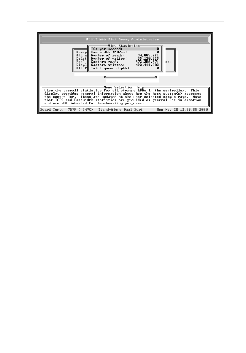
Configuration 79
Figure 50: View Statistics Screen
4. Press Esc to return to the Overall Statistics Menu.
FC-SCSI Dual RAID Module User's Guide - Rev. A01 StorCase Technology, Inc.
Page 93

80 Configuration
To access the read/write histogram:
1. Select Utilities Menu from the System Menu and press Enter.
The Utilities Menu should now display (Figure 45).
2. Select Overall Statistics and press Enter.
The Overall Statistics Menu should now display (Figure 49).
3. Select View R/W Histogram and press Enter.
The View R/W histogram should now display (Figure 51).
Figure 51: View R/W Histogram Screen
4. Press Esc to return to the Overall Statistics Menu.
StorCase Technology, Inc. FC-SCSI Dual RAID Module User's Guide - Rev. A01
Page 94

Configuration 81
Resetting Overall Statistics
This function allows the user to reset ALL of the overall statistics back to zero (useful when
monitoring performance or when performing benchmark testing).
NOTE: Resetting overall statistics will also reset the statistics for each individual partition
To reset the overall statistics:
1. Select Utilities Menu from the System Menu and press Enter.
2. Select Overall Statistics and press Enter.
3. Select Reset All Statistics and press Enter.
4. Select Yes and press Enter.
(refer to section " Resetting Partition Statistics" for further information).
The Utilities Menu should now display (Figure 45).
The Overall Statistics Menu should now display (Figure 49).
The system will now confirm your request to reset the statistics.
FC-SCSI Dual RAID Module User's Guide - Rev. A01 StorCase Technology, Inc.
Page 95

82 Configuration
Managing Spares
The controller will automatically reconstruct redundant (fault-tolerant) arrays (RAID 3, RAID
4, RAID 5, and RAID 50, and Mirrored) if an array becomes critical (and a sufficiently-sized
spare drive is available). An array becomes critical when one or more member drives fail.
The user can set up two (2) types of spare drives:
Dedicated - Available drive that is assigned to a specific array.
Pool - Available drive that is assigned to the pool, which can provide a spare for
any failed drive in any redundant array.
In addition, if the Dynamic Spares option is enabled and a drive fails, the drive can be replaced
and the controller will rescan the bus; it will then find the new disk drive and automatically start
reconstruction of the array.
The controller will look for a dedicated spare first. If it does not find a sufficiently-sized
dedicated spare, it will then look for a pool spare.
If a reconstruct does not start automatically, it means that there are no valid spares available.
To start a reconstruct, the user must:
1. Replace the failed drive, if no other drive is available.
2. Add the new drive or another available drive as a dedicated spare to the array (or as
a pool spare).
NOTE: Any pool spares added may be used by any critical array, and not necessarily by
the intended array.
Managing Dedicated Spares
Dedicated spares are unused disk drives that are assigned to a specific array. The disk must
be as large as the smallest member in the array. A dedicated spare drive cannot be used in
an array, nor as a pool spare.
Although using a dedicated spare is the most secure way of providing a spare for an array,
it is not very cost-effective keeping an idle drive assigned to the array. An alternative method
is to assign one or more idle drives to the spare pool (refer to section "Managing the Spare
Pool" for further information).
StorCase Technology, Inc. FC-SCSI Dual RAID Module User's Guide - Rev. A01
Page 96

Configuration 83
Adding a Dedicated Spare
This function allows the user to add dedicated spares to a specific array. If a member drive
in the array fails, the controller will use a dedicated spare drive to automatically reconstruct
the array. The user can add dedicated spares to Mirrored (RAID 1 and RAID 10) and parity
(RAID 3, RAID 4, RAID 5, and RAID 50) arrays at anytime. Up to four (4) dedicated spare drives
can be added to an array (refer to section "Creating Arrays" for further information).
NOTES: A spare cannot be added unless it has enough capacity to replace the smallest
To add a dedicated spare:
1. Select Array Menu from the System Menu and press Enter.
2. Select the desired array and press Enter.
3. Select Add Spare and press Enter.
4. Select the drive to add as a spare and press Enter.
5. Select Yes and press Enter.
member in the array.
If a drive was a member of an array and was removed from the array, it cannot be
used as a spare until all the metadata is cleared from the drive (refer to section
"Clearing Metadata from a Drive" for further information).
The Select Array screen will display, along with a list of existing arrays (Figure 19).
The Array Menu should now display (Figure 20).
The List of Available Drives screen should now display.
The system will confirm your request to add the spare.
FC-SCSI Dual RAID Module User's Guide - Rev. A01 StorCase Technology, Inc.
Page 97

84 Configuration
Deleting a Dedicated Spare
This function allows the user to delete a dedicated spare drive from an array at anytime.
To delete a dedicated spare:
1. Select Array Menu from the System Menu and press Enter.
The Select Array screen will display, along with a list of existing arrays (Figure 19).
2. Select the desired array and press Enter.
The Array Menu should now display (Figure 20).
3. Select Delete Spare and press Enter.
The List of Available Drives screen should now display.
4. Select the drive to delete as a spare and press Enter.
The system will confirm your request to delete the spare.
5. Select Yes and press Enter.
Enabling Dynamic Spares
This function allows the user to use all of the disk drives in redundant arrays, without assigning
one as a spare. For example, if the Dynamic Spares option is enabled and a drive fails, the
drive can be replaced and the controller will rescan the bus; it will then find the new disk drive
and automatically start reconstruction of the array.
With the Dynamic Spares option enabled, the controller will first look for a dedicated (or a pool
spare, if no dedicated drives are available) drive for reconstruction (if spares or drives are
available).
NOTES: The spare or available drive must have enough capacity to replace the smallest
StorCase Technology, Inc. FC-SCSI Dual RAID Module User's Guide - Rev. A01
member in the array, otherwise the controller cannot use it.
Make sure the spare or available drive does not contain any metadata (refer to
section "Clearing Metadata from a Drive" for further information).
Performance in systems without a SAF-TE Processor Board will decrease if an array
becomes critical (with this option enabled) and there are no available drives to start
a reconstruct. To minimize performance impact, increase the rescan rate.
Page 98

Configuration 85
To enable dynamic spares:
1. Select Configuration Menu from the System Menu and press Enter.
The Configuration Menu should now display (Figure 31).
2. Select Option Configuration and press Enter.
The Option Configuration Menu should now display (Figure 32).
3. Select Dynamic Spare Configuration and press Enter.
The Dynamic Spare Configuration screen will display (Figure 52).
The current setting is marked with an * next to it.
Figure 52: Dynamic Spare Configuration Screen
4. Select Enabled press Enter.
The Rescan Rate screen should now display.
5. Enter the rescan rate (in minutes).
This tells the controller how often it should look for an available drive by rescanning
the bus. Rescanning the bus frequently can affect performance.
The system will confirm the rescan rate.
6. Select Yes and press Enter.
FC-SCSI Dual RAID Module User's Guide - Rev. A01 StorCase Technology, Inc.
Page 99

86 Configuration
Managing the Spare Pool
The spare pool allows the user to have one or more disk drives available for the reconstruction
of redundant arrays (Mirrored and Parity). Once a drive is assigned to the spare pool, it is no
longer available for use as an array member or as a dedicated spare. If a pool spare is too
small (not enough capacity to replace the smallest member in the array), the controller cannot
use it.
Adding a Spare to the Spare Pool
This function allows the user to add up to eight (8) drives to the spare pool to reconstruct any
critical array on the controller. After an array has started using a pool spare, other critical
arrays are prevented from using it. If a pool spare is too small (not enough capacity to replace
the smallest member in the array), the controller cannot use it.
To add a pool spare:
1. Select Pool Spare Menu from the System Menu and press Enter.
The Pool Spare Menu should now display (Figure 53).
Figure 53: Pool Spare Menu Screen
2. Select Add Pool Spare and press Enter.
The Select Drives screen should now display (Figure 54).
StorCase Technology, Inc. FC-SCSI Dual RAID Module User's Guide - Rev. A01
Page 100

Configuration 87
Figure 54: Select Drives Screen
3. Select drive(s) to add as spares and press Enter.
Deleting a Spare from the Spare Pool
This function allows the user to delete a spare from the spare pool at anytime.
To delete a spare from the spare pool:
1. Select Pool Spare Menu from the System Menu and press Enter.
The Pool Spare Menu should now display (Figure 53).
2. Select Delete Pool Spare and press Enter.
The Delete Pool Spare screen will display, along with a list of drives assigned to the
pool spare.
3. Select the pool spare to delete and press Enter.
FC-SCSI Dual RAID Module User's Guide - Rev. A01 StorCase Technology, Inc.
 Loading...