

Page 1

DX500-BBRKT
DS500 Battery Bracket
(Part Number DX500-BBRKT)
StorCase will not be responsible for any damages caused by improper installation of this
product. READ THESE INSTRUCTIONS CAREFULLY!
CAUTION: Remove ALL power from the DS500 before removing any chassis
covers.
Danger of explosion if battery is incorrectly installed! Install only with
the same or equivalent type battery recommended by the manufacturer. Dispose of used batteries according to manufacturer's
instructions.
DO NOT SHIP/TRANSPORT DS500 CHASSIS WITH BATTERY
INSTALLED! Battery may loosen from bracket which can result in fire
and/or explosion!
NOTES: The DS500 Battery Bracket is designed to house a RAID-compatible
back-up battery with approximate dimensions of 6"(L) x 4"(H) x 1"(W)
or 6"(L) x 4"(H) x 2"(W).
This option is designed only for DS500 units containing Rev. G and
above Motherboard Mounting Brackets. Rev. F and earlier
Motherboard Mounting Brackets can be identified by an open slot and
do not have the mounting holes required to mount the Battery Bracket.
(Figure 2).
This document provides information for installing the StorCase DS500 RAID controller
Battery Bracket (DX500-BBRKT) into either a tower or rack mount DS500 9-bay chassis.
These instructions supplement the DS500 User's Guide which should be used for
additional reference during the conversion process.
469a
Figure 1: DS500 Battery Bracket
D89-0000-0049 Rev. B00 StorCase Technology, Inc.
Page 2
DX500-BBRKT
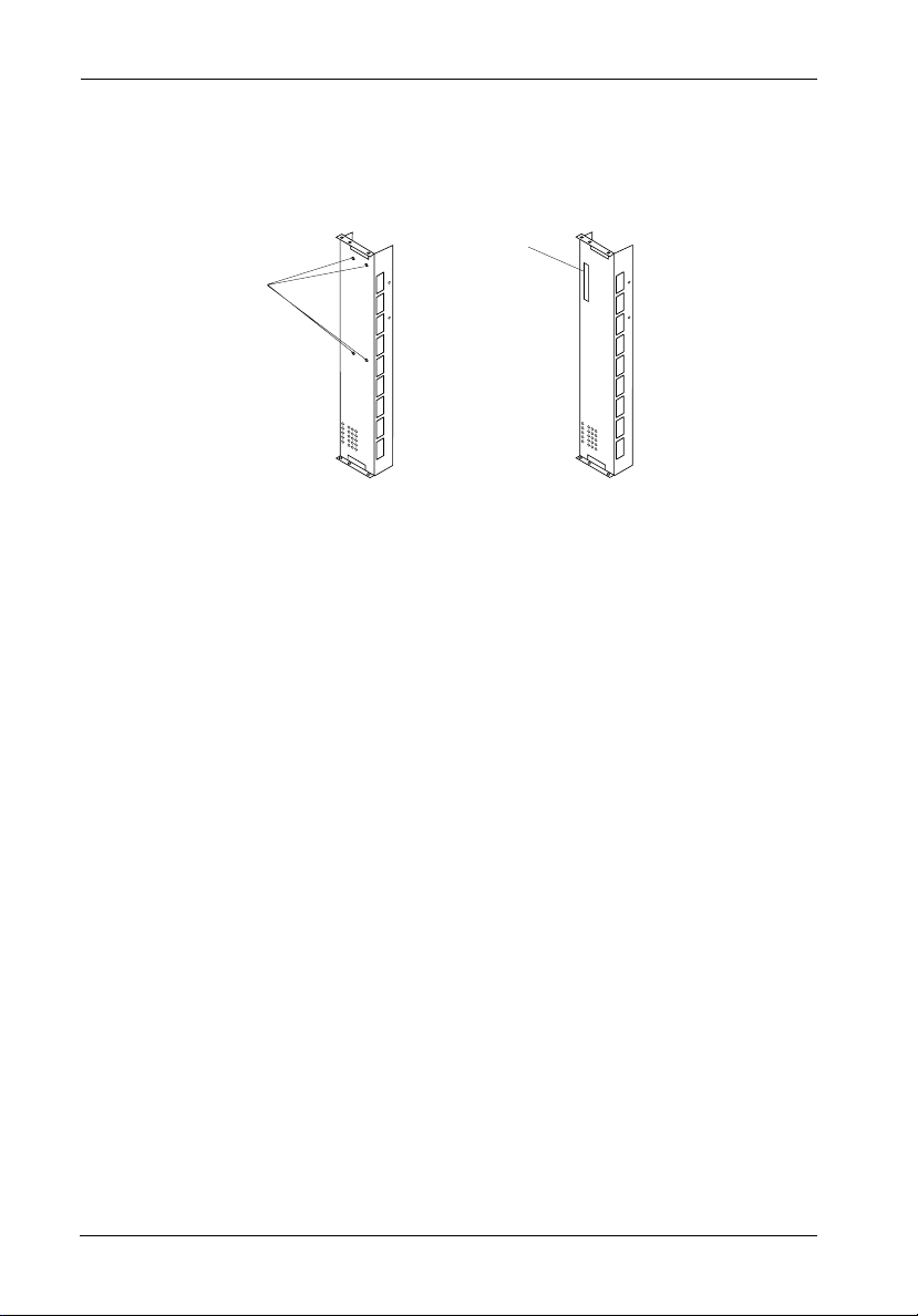
4 Mounting Holes
for Mounting
Battery Bracket
DS500 Motherboard Mounting Bracket
Open
Slot
Rev. G
(Compatible with
Battery Bracket)
469c
Rev. F and Earlier
(Not Compatible
with Battery Bracket)
Figure 2: Distinguishing Between DS500 Motherboard
Mounting Bracket Revisions
Installation
A #2 Phillips screwdriver is required to complete the following steps.
1. If installing the Battery Bracket into a rack mounted DS500, both the front and
StorCase Technology, Inc. D89-0000-0049 Rev. B00
rear panels will need to be removed.
Remove the eight (8) screws and the front panel as shown in Figure 3.
Page 3

DX500-BBRKT
Figure 3: Removing the Rack Mount Front Panel
Remove the eight (8) screws and the rear panel as shown in Figure 4.
Top Rear Cover
Screw Location
(8 plcs)
0270
Remove this cover to install/remove I/O connectors or to route
cables in the rear portion of the chassis.
Figure 4: Removing the Rack Mount Rear Panel
D89-0000-0049 Rev. B00 StorCase Technology, Inc.
Page 4

DX500-BBRKT
2. If adding the Battery Bracket to a DS500 tower, remove the right side panel as
shown in Figure 5.
Figure 5: Removing the Side Panel
3. Install the Battery Bracket into the DS500 as shown in Figure 6.
StorCase Technology, Inc. D89-0000-0049 Rev. B00
Page 5

Attach the Battery
Bracket to the DS500
Motherboard Mounting
Bracket with the 4
Countersink
screws provided
Battery
Bracket
469f
DS500
Motherboard
Mounting Bracket
DX500-BBRKT
Figure 6: Attaching the Battery Bracket to the DS500
Motherboard Mounting Bracket
4. Once the bracket is secured to the DS500 Motherboard Mounting Bracket, insert
and secure the battery as shown in Figures 7 and 8. Be careful not to damage
the battery terminals when installing the battery into the bracket. Refer to the
RAID controller manufacturer's instructions for battery type and connection
information.
NOTE: Insert battery into the
Battery Bracket after the
bracket is secured to the
DS500 Motherboard
Mounting Bracket.
1
Insert Battery into the
Battery Bracket.
2
Attach with (2) #6-32
Phillips Pan Head
screws provided
469b
Battery
(Not Included)
Figure 7: Installing the Battery into the Battery Bracket Overview
D89-0000-0049 Rev. B00 StorCase Technology, Inc.
Page 6

DX500-BBRKT
Insert battery (Not Included)
into the Battery Bracket.
DX500-BBRKT
Battery Bracket
Slot for
Adjustability
2
Attach with (2)
#6-32 Phillips
Pan Head screws
1
provided
469e
With a 1 wide
battery, use the
hole on the left
With a 2 wide
battery, use the
hole on the right
Figure 8: Installing the Battery into the Battery Bracket
NOTE: StorCase does not supply the battery cables. Contact the RAID controller
manufacturer for cable information.
4. Verify that the battery has been properly connected to the RAID controller per
the manufacturer's instructions.
5. Reinstall all DS500 screws and side panels removed earlier.
6. Connect all cables and power cords removed earlier.
StorCase Technology, Inc. D89-0000-0049 Rev. B00
 Loading...