

Page 1
DX150-ZIPKIT Installation 1
DX150-ZIPKIT Installation Instructions
This document provides detailed installation information for the StorCase DX150-ZIPKIT. This kit
adapts one internal ZIP® drive to the open front Data Express® carrier unit (P/N DE150i-CSD).
Refer to the StorCase Data Express User's Guide for additional operating and installation
information. Refer to the device manufacturer's documentation for additional information
regarding jumper settings, connector locations, and operating instructions.
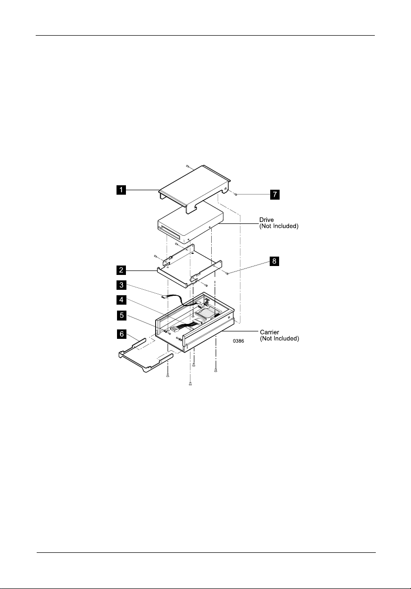
Figure 1: DX150-ZIPKIT Illustrated Parts Breakdown
The DX150-ZIPKIT includes the following items:
1. Drive Cover 1 ea.
2. Drive Bracket 1 ea.
3. ID Select Cable 1 ea.
4. Power Cable Adapter 1 ea.
5. Filament Washer 4 ea.
6. Low Profile Carrier Handle 1 ea.
7. #6-32 x 0.230" Flat Hd. Screw 4 ea.
8. M3, Phillips Flat Hd. Screw 8 ea.
Please note that the drive and carrier unit shown in the illustration above ARE NOT part of the
DX150-ZIPKIT.
DX150-ZIPKIT User's Guide - Rev. A01 StorCase Technology, Inc.
Page 2
2 DX150-ZIPKIT Installation
1. Unpack the DX150-ZIPKIT and compare it with the Illustrated Parts Breakdown shown
in Figure 1 for an overview of the entire assembly to verify that the kit is complete. A
#2 Phillips screwdriver is required to complete the installation.
2. If installing the DX150-ZIPKIT into a carrier unit that already has an installed drive, remove
the power, I/O and ID select cables from the drive. Remove the drive from the carrier.
3. Place the Data Express carrier unit on a soft, clean surface to protect the finish. Choose
a suitable area that allows ample working space around the unit.
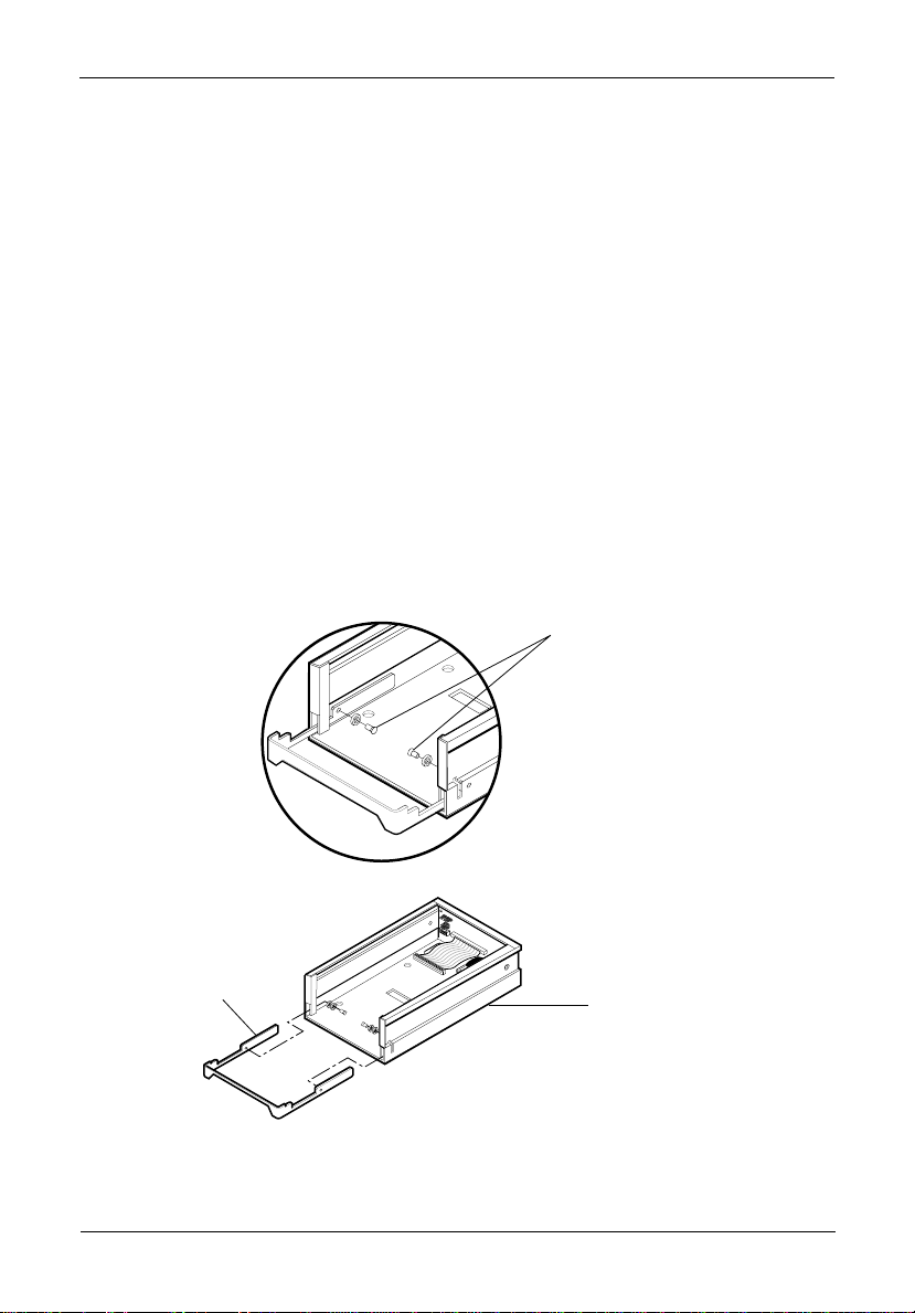
4. Remove the handle and replace it with the new low-profile handle included in the kit, as
shown in Figure 2.
Fully extend the existing handle and carefully remove the two (2) #6-32 x .230" retaining
screws with a Phillips screwdriver. Remove and replace the handle with the new low
profile handle (new handle uses two filament washers per screw).
With the handle fully
extended, remove the two
retaining screws.
Remove Existing
Open Front Carrier Handle
Low Profile
Handle
Carrier
(Not Included)
0382
Figure 2: Replacing the Handle
StorCase Technology, Inc. DX150-ZIPKIT User's Guide - Rev. A01
Page 3

DX150-ZIPKIT Installation 3
5. Attach the drive to the adapter bracket using four (4) M3 screws, as shown in Figure
3.
6. Attach the Power Cable Adapter (included) to the Data Express power cable (Figure 1).
7. Attach the ID select cable (included - Figure 4), the I/O and power cables to the drive.
Refer to the Data Express User's Guide and the drive manufacturer's documentation for
information on these procedures.
Drive Sits Flush with Drive
Bracket Filler Panel
Drive
(Not Included)
M3 x 5MM
Screws (4 ea.)
Drive Bracket
0616
Figure 3: Installing the Drive Into the Bracket
I/O Connector
Data Express
Carrier Board
ID Select
Cable (Black)
(Pin 1)
Zip Drive
Rear Panel
Power
Connector
(Red)
ID Select
Cable (Black)
0615
Figure 4: Connecting the ID Select Cable
DX150-ZIPKIT User's Guide - Rev. A01 StorCase Technology, Inc.
Page 4

4 DX150-ZIPKIT Installation
8. Place the Drive Bracket assembly into the carrier unit and fasten in place with four (4)
M3 Phillips flat hd. screws as shown in Figure 5.
9. Complete the installation by installing the cover (Figure 6). Carefully insert the sides of
the cover between the carrier and the drive. Slide the cover towards the rear of the
carrier making certain that the lip on the rear portion of the cover is underneath the lip
on the rear of the carrier. Fasten the cover to the carrier with two (2) #6-32 x 0.230"
Flat Hd. screws.
Drive
Bracket
Carrier
(Not Included)
Cables are not shown attached to the carrier
in this illustration for clarity.
M 3x5 MM Phillips
Flat HD Screws
(4 ea.)
0617
Figure 5: Installing the Bracket Assembly into the Carrier
Drive Cover
6-32 x .230"
Flat HD Screws
(2 ea.)
0618
Figure 6: Attaching the Cover the Carrier
StorCase Technology, Inc. DX150-ZIPKIT User's Guide - Rev. A01
 Loading...