

Page 1

StorCase® Technology
Data Stacker
®
DS60
External SCSI
Expansion Chassis
Installation Instructions
Page 2
StorCase® Technology
DS60
Data Stacker
External SCSI
Expansion Chassis
Installation Instructions
Part No. D89-0000-0066 C02 August 2002
®
i
StorCase Technology, Inc.
17600 Newhope Street
Phone (714) 438-1850 Fax (714) 438-1847
DS60 Installation Instructions - Rev. C02 StorCase Technology, Inc.
Fountain Valley, CA 92708-9885
Page 3

ii
Important Safety Instructions
1. Read all these instructions.
2. Save these instructions for later use.
3. Follow all warnings and instructions marked on the product.
4. Do not use this product near water.
5. This product should be operated from the type of power source indicated on the
marking label. If you are not sure of the type of power available, consult your dealer
or local power company.
6. Do not attempt to service this product yourself, as opening or removing covers may
expose you to dangerous voltage points or other risk. Refer all servicing to service
personnel.
Wichtige Sicherheitshinweise
1. Diese Hinweise sollten vollständig durchgelesen werden.
2. Diese Hinweise für einen späteren Gebrauch aufbewahren.
3. Allen auf dem Gerät angebrachten Warnungen und Hinweisen folgen.
4. Das Gerät nicht in der Nähe von Wasser verwenden.
5. Das Gerät nur mit dem Aufkleber bezeichneten Netzspannung betreiben. Bei
Fragen über die Art der Netzspannung sollte der Händler oder das
Energieversorgungsunternehmen zu rate gezogen werden.
6. Nicht versuchen das Produkt selbst zu reparieren. In allen Produkten existieren
gefährliche elektrische Spannugen. Nicht das Gehäuse öffnen.
7. Wartungsarbeiten nur von qualifiziertern Kundendienstpersonal ausführen
StorCase Technology, Inc. DS60 Installation Instructions - Rev. C02
Page 4
Installation 1
DATA STACKER INSTALLATION
Installing the Drive(s) into the Data Stacker
While performing the steps in this section, work on a soft surface to prevent excessive shock
to the drive(s) being installed. Also refer to the manufacturer's documentation provided with
the drive(s). Phillips #1 and #2 screwdrivers will be required during this procedure.
NOTE: For the DS60 2-bay model, always install bottom drive first!
Removing the DS60 Cover
WARNING: Remove ALL power from the Data Stacker before removing the cover. The Data
1. Unplug the Data Stacker and verify that ALL cables have been disconnected.
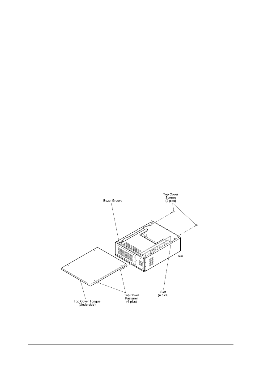
2. Remove the two (2) screws located on the back of the unit as shown (Figure 1).
3. Carefully slide the cover forward, then lift upward and off the chassis.
Stacker contains NO USER SERVICEABLE PARTS inside the unit.
Figure 1: Removing the Cover
DS60 Installation Instructions - Rev. C02 StorCase Technology, Inc.
(1-Bay Shown)
Page 5

2 Installation
Drive Preparation
1. Remove the drive from its protective packaging.
2. Plastic Drive Bezel - If installing a hard drive which is equipped with a plastic front
bezel, remove the drive bezel.
3. SCSI Drive Termination - Disable SCSI termination from the drive. Refer to the
documentation provided by the drive manufacturer for the location of these terminators
or jumpers. Termination is provided by an external terminator on the Data Stacker rear
panel. External active termination is recommended for best SCSI performance
(terminator not included with the Data Stacker).
4. SCSI Drive ID Select Jumpers - Locate the SCSI ID select jumper pins on the drive,
and remove any jumpers on these pins. The Data Stacker SCSI ID cable will be attached
to these pins on each drive (Figures 7 and 8). Refer to the device manufacturer's
documentation for the location of these pins.
Drive Installation
NOTE: For the DS60 2-bay model, always install bottom drive first!
Removal of the Data Stacker chassis side panel (Figure 2) and sliding drive bracket (Figure
3) is required in order to install the drive. Once the drive is installed into the bracket, the entire
drive/bracket assembly can then be reinstalled into the DS60 chassis.
1. Remove the two chassis side panel screws (Figure 2).
2. Gently slide the panel toward the rear of the chassis, then pull straight out to remove.
3. Remove the sliding drive bracket retaining screw (Figure 3).
4. Remove the drive mounting bracket from the chassis by sliding it out through the front
bezel. Be careful not to damage the connector pins on the backside of the bezel (behind
the LEDs).
StorCase Technology, Inc. DS60 Installation Instructions - Rev. C02
Page 6

Installation 3
Figure 2: Removing the Chassis Side Panel
Figure 3: Removing the Sliding Drive Bracket
DS60 Installation Instructions - Rev. C02 StorCase Technology, Inc.
Page 7

4 Installation
5. If installing a removable media device, replace the slot patterned drive bezel with the
open front drive bezel as shown in Figure 4. The bezel can easily be removed by
applying gentle pressure with the tip of a flat blade screwdriver.
6. Install the drive(s) into the drive mounting bracket. Side-mount 1-inch high drives (i.e.
DAT drives) using four (4) M3 x 5 metric screws (Figure 5). Make certain that
removable media devices align with the drive bezel. Bottom mount hard drives with
#6-32 x 0.230" screws (Figure 6).
NOTE: If installing a 1" high front-loading device, side-mount it to the drive bracket and
install the appropriate filler panel to the top of the drive bezel as shown in Figure
5.
Figure 4: Replacing the Drive Bezel
StorCase Technology, Inc. DS60 Installation Instructions - Rev. C02
Page 8

Installation 5
Figure 5: Installing a Removable Media 1" High Drive
DS60 Installation Instructions - Rev. C02 StorCase Technology, Inc.
into the Sliding Drive Bracket
Figure 6: Installing a Hard Drive
Page 9

6 Installation
7. SCSI ID Cable - One SCSI ID select cable is provided per each Data Stacker drive bay.
The ID cable permits external unit ID selection via a small switch located behind a sliding
door on the front panel of the Data Stacker. This cable provides 2mm connectors and
attaches to the drive SCSI ID pins. It is secured to the sliding drive bracket with tiewraps.
IF INSTALLING AN 8-BIT SCSI DEVICE:
The SCSI ID cable contains single black, brown, red, and orange wires. Attach three
(3) connectors from the SCSI ID select cable to the appropriate 2mm drive pins (Figure
7). The fourth (orange) wire is not used for the 8-bit installation.
The black wire plugs into the drive pin used to select ID0, the brown wire plugs into
the drive pin for ID1, the red wire plugs into the drive pin for ID2. The orange wire
is not used for this interface.
In most cases, the drive manufacturer labels each pair of SCSI ID select pins in
significant bit order (0, 1 and 2). One row of drive pins is the signal row, and one row
is designated for ground. Refer to the drive manufacturer's documentation for specific
pin configurations.
The Data Stacker ID select cable provides 2mm, 2-conductor drive connectors. A
single wire attaches to one side of each connector. The cable side of each connector
must align with the signal pin on the drive.
Figure 7: 8-Bit SCSI ID Cable Connection
StorCase Technology, Inc. DS60 Installation Instructions - Rev. C02
Page 10

Installation 7
2mm ID Select Cable from
Data Stacker ID Select Switch
Orange (ID3)
Signal Row
GND Row
Black (ID0)
Brown (ID1)
Red (ID2)
IF INSTALLING A 16-BIT SCSI DEVICE:
The SCSI ID cable contains black, brown, red, and orange wires. Attach four (4)
connectors from the SCSI ID select cable to the appropriate 2mm drive pins (Figure 8).
The black wire plugs into the drive pin used to select ID0, the brown wire plugs into
the drive pin for ID1, the red wire plugs into the drive pin for ID2, and the orange wire
plugs into the drive pin to select ID3.
In most cases, the drive manufacturer labels each pair of SCSI ID select pins in
significant bit order (0, 1, 2 and 3). One row of drive pins is the signal row, and one
row is designated for ground. Refer to the drive manufacturer's documentation for
specific pin configurations.
The Data Stacker ID select cable provides 2mm, 2-conductor drive connectors. A
single wire attaches to one side of each connector. The cable side of each connector
must align with the signal pin on the drive.
Figure 8: 16-Bit SCSI ID Cable Connection
DS60 Installation Instructions - Rev. C02 StorCase Technology, Inc.
Page 11

8 Installation
8. Locate the device activity connector on the drive and connect the black/green wires
to these pins. Black is connected to the cathode output and green is connected to the
anode output.
9. Locate the device fault connector on the drive and connect the black/yellow wires to
these pins. Black is connected to the cathode output and yellow is connected to the
anode output.
Refer to the device manufacturer's documentation for the location of these pins.
10. Carefully reinstall the sliding drive bracket/drive into the Data Stacker chassis and
fasten it into place with the retaining screw.
IMPORTANT NOTE: Be careful not to damage the connector pins on the backside of the
11. Attach the 4-pin DC power cable to the drive.
12. Attach the I/O cable to the drive.
13. Reinstall the chassis side panel.
14. Reinstall the Data Stacker top cover in the reverse manner in which it was removed.
Make certain that the tongue on the underside of the cover mates with the groove in
the front bezel (Figure 1).
15. Connect the power cable to the Data Stacker and turn on the power switch. Should
there be any unusual sound, turn the Data Stacker off immediately, disconnect the
power cable, and remove the cover to locate the source of the problem. Verify that
the power, SCSI ID select cables and LED cables are securely fastened with the
provided tie wraps and are not contacting the fan. Replace the cover.
interchangeable drive bezel (behind the LEDs) when installing the
sliding drive bezel into the chassis! If you encounter resistance,
do not force the bracket into place!
StorCase Technology, Inc. DS60 Installation Instructions - Rev. C02
Page 12

Installation 9
Connecting the Data Stacker to the Computer System
If the DS60 is the last device in a SCSI daisy chain, it will require the appropriate termination
(Figure 9).
Figure 9: Typical Daisy Chain Connections
DS60 Installation Instructions - Rev. C02 StorCase Technology, Inc.
Page 13

10 Installation
Selecting the SCSI ID Number and Fan Speed
The SCSI ID is an address number (0 through 7 for 8-bit interface and 0 through 15 for 16-bit
interface) that is assigned to each SCSI device. In a SCSI daisy-chain, each device in the chain
must have a unique SCSI ID number. SCSI ID 7 is usually reserved for the host controller. If
the computer system is already equipped with internal or external SCSI storage devices, some
ID numbers will already be reserved. For instance, if the computer system came with an internal
SCSI hard drive, it may be designated as SCSI device 0. Refer to the computer system
documentation for additional information.
The Data Stacker SCSI ID selection switch(es) is located on the front panel of the chassis
enclosure, concealed behind a sliding door (Figure 10). The rotating switch can be adjusted
with the provided adjustment tool.
Carefully select the appropriate SCSI ID number(s) for the installed device(s). Note that some
switch settings may be invalid for your interface type. Selecting an invalid ID number, or
selecting the same number on different devices may cause unpredictable results and the
computer system may not recognize the installed device(s). If the computer system can not
recognize the boot disk, the computer system may fail to properly start-up.
NOTE: A small dip switch located below the rotating SCSI ID selection switch is provided
for fan speed adjustment. The fan may be set for high or low speed (Figure 12).
Figure 10: SCSI ID Selection Switch and Fan Speed Switch
StorCase Technology, Inc. DS60 Installation Instructions - Rev. C02
Page 14

Installation 11
Figure 11: SCSI ID Selection Switch Settings
The Fan Speed Selector Switch (Figure 12) has two settings - High and Low speed. High speed
(factory setting) is suitable for all drive capacities but is recommended for drives exceeding
4GB. Low speed may be used for removable media drives or drives with less than 4GB.
Figure 12: Fan Speed Switch
DS60 Installation Instructions - Rev. C02 StorCase Technology, Inc.
Page 15

12 Installation
This Page Left Blank Intentionally.
StorCase Technology, Inc. DS60 Installation Instructions - Rev. C02
 Loading...