

Page 1

Kingston Technology
Data Silo
®
DS350
External SCSI Expansion Chassis
User's Guide
Page 2

Kingston Technology
DS350
i
Data Silo
®
External SCSI Expansion Chassis
User's Guide
Part No. D89-0000-0089 A00 May 1999
Kingston Technology Company
17600 Newhope Street
Phone (714) 438-1850 Fax (714) 438-1847
DS350 User's Guide - Rev. A00 Kingston Technology Company
Fountain Valley, CA 92708-9885
Page 3

Kingston Storage Products Warranty & Return Guidelines
KINGSTON TECHNOLOGY COMPANY'S STORAGE PRODUCT DIVISION warrants that its core
products are free from defects in material and workmanship. Subject to the conditions and
limitations set forth below, Kingston will, at its option, either repair or replace any part of its
product that proves defective by reason of improper workmanship or materials. Repair parts
or replacement products will be provided by Kingston on an exchange basis, and will be either
new or refurbished to be functionally equivalent to new.
Core products that have been slightly modified (e.g. paint, handle, etc.) by Kingston will be
covered for repair only, for the same warranty period specified for the unmodified version
of the product, as defined below. Special request designs are not subject to Kingston's
standard warranty and will be assigned a product-specific warranty at the time of bid. Stock
rotation and return for credit does not apply to modified and/or new design products.
This warranty does not cover any product damage that results from accident, abuse, misuse,
natural or personal disaster, external power surge or failure, or any unauthorized disassembly, repair or modification. Kingston will not be responsible for any software, firmware or other
customer data stored within, or interfacing with a Kingston Storage Product.
Duration of Warranty
Seven Year Warranty: The following Kingston Storage Products are covered by this
warranty for a period of seven years from the date of original end user purchase: all Data
Silo® and Data Stacker external chassis, all Data Express® removable device carriers and
receiving frames, and all integrated or separately-purchased power supplies, cooling fans,
interface cables, terminators, and any other Kingston accessories specifically meant for use
with these products.
ii
Modified Product Warranty: Under certain agreements where Kingston core products
are slightly modified (e.g. paint, handle, etc.) by Kingston at the customer's request, the
products will be covered for repair only, for the same duration defined for the unmodified
version of the product.
Special Request Product Warranty: Kingston's warranty for component-level modifications, or for products newly-designed to meet a specific customer's request will be negotiated
with the applicable customer on a case-by-case basis.
Return Policy:
Kingston offers a 30-day "no questions asked" return policy (from the original date of end user
purchase) on all core Storage Products. Products returned within the 30-day period must be
returned in the original Kingston shipping package and in new condition. Product returned
beyond the 30-day period is eligible for repair only. Modified products or special request
designs may be returned for repair only, as defined above.
DS350 User's Guide - Rev. A00 Kingston Technology Company
Page 4

Warranty Claim Requirements
To obtain warranty service, the defective product must be returned to your local authorized
Kingston dealer or distributor, or to the Kingston factory service center.
For defective returns directly to Kingston, shipments must be freight-prepaid and
insured, and must include the product serial number, a detailed description of the problem
experienced, and proof of the original retail purchase date. A Return Material Authorization
("RMA") number must also be obtained by calling Kingston Customer Service at (714) 445-
3455. The RMA number must be prominently displayed on the outside of the return package.
Products must be properly packaged to prevent damage in transit and to allow Kingston to
issue full credit. The Kingston factory service center is located at 17580 Newhope Street,
Fountain Valley, California 92708, U.S.A.
Free Technical Support
Kingston provides free technical support. If you experience any difficulty during the installation
or subsequent use of a Kingston product, please contact the Kingston Technical Support
Department at either (888) 435-5460 or (714) 438-1858 prior to servicing your system. This
warranty covers only repair or replacement of defective Kingston products, as described
above. Kingston is not liable for, and does not cover under warranty, any costs associated
with servicing and/or installation of Kingston products.
Disclaimers
The foregoing is the complete warranty for Kingston Storage Products and
supersedes all other warranties and representations, whether oral or written.
Except as expressly set forth above, no other warranties are made with respect
to Kingston Storage Products and Kingston expressly disclaims all warranties not
stated herein, including, to the extent permitted by applicable law, any implied
warranty of merchantability or fitness for a particular purpose. In no event will
Kingston be liable to the purchaser, or to any user of the Kingston product, for any
damages, expenses, lost revenues, lost savings, lost profits, or any other
incidental or consequential damages arising from the purchase, use or inability
to use the Kingston Storage Product, even if Kingston has been advised of the
possibility of such damages.
iii
Copyright© 1999 Kingston Technology. All rights reserved. All registered trademarks are the
property of Kingston Tecnology. Printed in the U.S.A.
DS350 User's Guide - Rev. A00 Kingston Technology Company
Page 5

Declaration of Conformity
iv
Companys Name:
Companys Address:
Manufacturers Address:
Product Name:
Model Number:
Conforms to the following specifications:
Safety Agencies:
CSA (NRTL/C)
TÜV
Safety Directive:
EMC Directive:
Kingston Technology Company
Storage Products Division
17600 Newhope Street
Fountain Valley, CA 92708
17600 Newhope Street
Fountain Valley, CA 92708
Data Silo DS350
DS350-XX/X
Safety Tests:
CAN/CSA-C22.2 No950-93
UL 1950
EN 60950: 1992
A1+A2+A3+A4+A11
CB Scheme G 9973039.01
73/23/EEC low voltage
EMC Tests:
EN 50081-1:1992 for Generic Emission
CISPR22:1995/EN 55022:1987 Class A
EN 50082-1:1992 for Generic Immunity
IEC 1000-4-2:1994 ESD
IEC 1000-4-3:1994 Radiated EM Field
IEC 1000-4-4:1994 Fast Transient/Burst
89/336/EEC
FCC Part 15, Class A
Reference #:
LR 90843-17
E 9973038.01
Year of Manufacture:
Signature:___________________
Full name: Dieter Paul
Position: Vice President of Engineering
DS350 User's Guide - Rev. A00 Kingston Technology Company
1999
Page 6

Important Safety Instructions
1. Read all these instructions.
2. Save these instructions for later use.
3. Follow all warnings and instructions marked on the product.
4. Do not use this product near water.
5. This product should be operated from the type of power source indicated on the
marking label. If you are not sure of the type of power available, consult your
dealer or local power company.
6. Do not attempt to service this product yourself, as opening or removing covers
may expose you to dangerous voltage points or other risk. Refer all servicing to
service personnel.
Wichtige Sicherheitshinweise
1. Diese Hinweise sollten vollständig durchgelesen werden.
2. Diese Hinweise für einen späteren Gebrauch aufbewahren.
3. Allen auf dem Gerät angebrachten Warnungen und Hinweisen folgen.
4. Das Gerät nicht in der Nähe von Wasser verwenden.
5. Das Gerät nur mit dem Aufkleber bezeichneten Netzspannung betreiben. Bei
Fragen über die Art der Netzspannung sollte der Händler oder das
Energieversorgungsunternehmen zu rate gezogen werden.
6. Nicht versuchen das Produkt selbst zu reparieren. In allen Produkten existieren
gefährliche elektrische Spannugen. Nicht das Gehäuse öffnen.
7. Wartungsarbeiten nur von qualifiziertern Kundendienstpersonal ausführen
laßen.
v
DS350 User's Guide - Rev. A00 Kingston Technology Company
Page 7

Table of Contents
DATA SILO DS350 INTRODUCTION ..................................................................................... 1
Packaging Information .................................................................................................. 1
Serial Number ................................................................................................................ 1
General Description ...................................................................................................... 2
DS350 Front Panel ................................................................................................ 4
DS350 Rear Panel ................................................................................................ 5
DS350 INSTALLATION .......................................................................................................... 6
Installing the Drive(s) into the DS350 .......................................................................... 6
Removing the Access Panel ................................................................................ 6
Drive Preparation .................................................................................................. 7
Removing the Drive Bracket ................................................................................ 7
Installing the Drive into the Bracket ..................................................................... 8
Connecting the DS350 to the Computer System ...................................................... 11
APPENDICES ........................................................................................................................ 13
Appendix A - Specifications/Dimensions .................................................................. 14
Appendix B - Drive Interface Adapter Options ........................................................ 16
Appendix C - Cables, Connectors, and Terminators ................................................ 17
Appendix D - Slide Rail Kit .......................................................................................... 24
vi
Reader's Comments ............................................................................................................ 25
DS350 User's Guide - Rev. A00 Kingston Technology Company
Page 8

List of Figures
Figure 1: Data Silo DS350 .............................................................................................. 2
Figure 2: DS350 Drive Installation Overview ............................................................... 3
Figure 3: DS350 Front Panel.......................................................................................... 4
Figure 4: DS350 Rear Panel .......................................................................................... 5
Figure 5: Access Panel ................................................................................................. 6
Figure 6: Removing the Drive Bracket .......................................................................... 7
Figure 7: Removing the Filler Panel ............................................................................... 8
Figure 8: Installing a Drive into the Drive Bracket ........................................................ 9
Figure 9: Installing the Drive/Bracket Assembly into the Chassis ............................... 9
Figure 10: DS350 Power Strip ...................................................................................... 10
Figure 11: Typical Daisy-Chain Connections ................................................................ 11
Figure 12: Dual Host Daisy-Chain Connection.............................................................. 12
Figure A-1: DS350 Physical Dimensions ........................................................................ 15
Figure B-1: Drive Interface Adapters ............................................................................. 16
Figure D-1: Rack Mount Slide Rail Kit .............................................................................. 24
List of Tables
vii
Table C-1: External Cables and Part Numbers .................................................................... 17
Table C-2: International Power Cables ................................................................................ 19
Table C-3: System Connectors ............................................................................................ 20
Table C-4: Terminators ......................................................................................................... 21
Table C-5: Internal SCSI Cables ........................................................................................... 23
NOTICE: This User's Guide is subject to periodic updates without notice. Please check Kingston's
DS350 User's Guide - Rev. A00 Kingston Technology Company
website at http://www.kingston.com or contact your Kingston representative for the latest
revision of this document.
Page 9

This Page Left Blank Intentionally.
viii
DS350 User's Guide - Rev. A00 Kingston Technology Company
Page 10

Introduction 1
DATA SILO® DS350 INTRODUCTION
PackagingInformation
The Kingston Technology Data Silo® external expansion chassis is shipped in a container
designed to provide protection and prevent damage during shipment. The Data Silo was
carefully inspected before and during the packing procedure at the factory. Evidence of any
damage to the Data Silo should be reported to the shipper immediately.
If the wrong Data Silo model has been received, please call Kingston's Storage Product Division
at (800) 435-0642. A staff member will give you a Return Material Authorization (RMA) number
to facilitate processing. Kingston cannot accept returns which do not display an RMA number
on the outside of the package. Return the unit with all the original packing materials.
Before removing any component from its packaging, discharge any static electricity by
touching a properly grounded metal object.
Serial Number
The Data Silo is labeled with a serial number. This number must be reported to the Kingston
Customer Service Representative in order to receive a Return Material Authorization (RMA)
for warranty claims. Locate the serial number label and record the number in the space
provided below.
Data Silo Serial Number:
DS350 User's Guide - Rev. A00 Kingston Technology Company
Page 11
2 Introduction
GeneralDescription
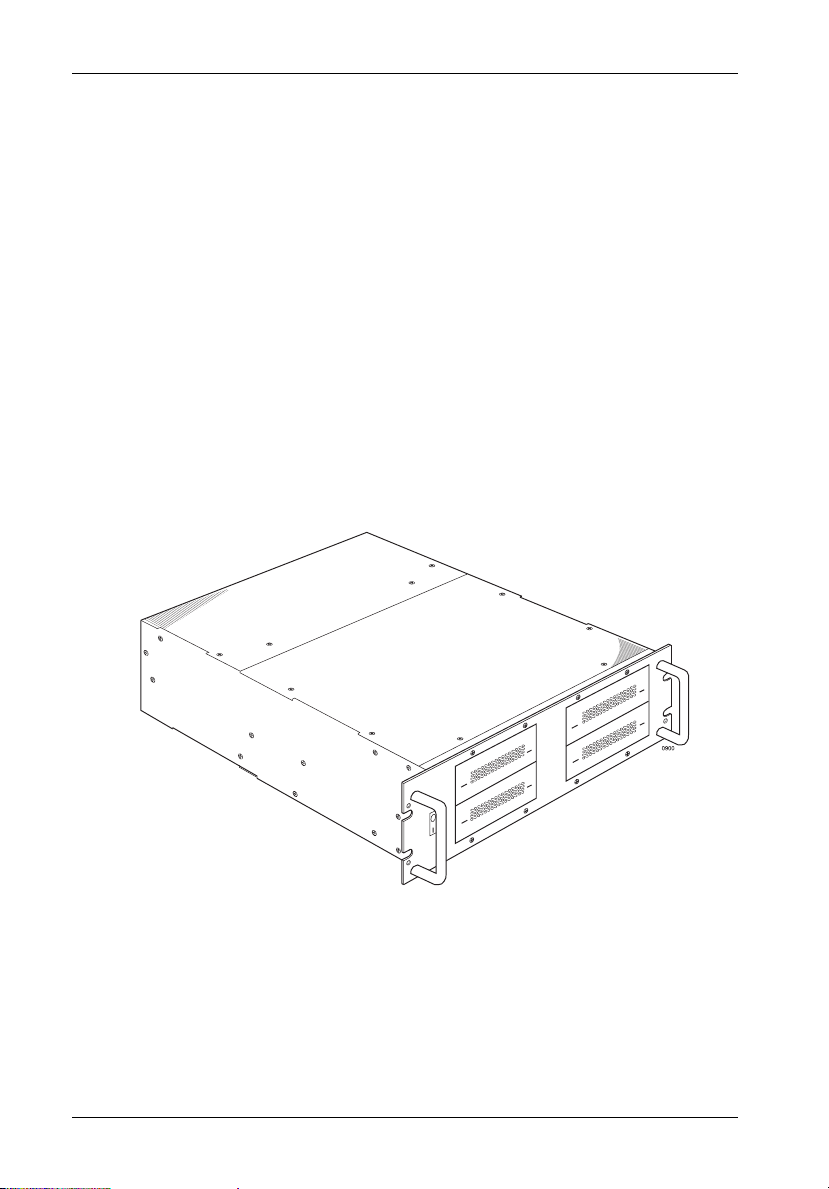
The Kingston Technology Data Silo® DS350 expansion chassis provides rugged and reliable
housing for SCSI storage devices. The DS350 is designed to support 3.5 inch and 5.25 inch
form factor, full-height, half-height, and low profile (1 inch high) removable media devices. The
DS350 can house Kingston's own Data Express® removable drive enclosures as well.
The DS350 is available in a rack mount, quad (4) bay configuration (Figure 1). Each chassis
is constructed of rugged steel and is equipped with two (2) 65 watt, auto-ranging power
supply(ies), power-on LEDs, three (3) high-speed cooling fan(s), and all necessary mounting
hardware.
The DS350 can support single or dual-host 50-pin MM (HD50) SCSI 2, 68-pin Wide SCSI 3, and
Wide 68-pin VHDCI (used for Ultra2 LVD) interfaces. Internal cables for the DS350 are not
included and must be ordered separately, providing either two (2) or four (4) drive daisy-chain
connections. Refer to Appendix C for these and other available cable options.
Figure 1: Data Silo DS350
Kingston Technology Company DS350 User's Guide - Rev. A00
Page 12

Introduction 3
This User's Guide describes the steps required for installing drive(s) into the DS350 external
expansion chassis.
This guide is intended to supplement documentation provided with the host computer system,
the operating system, and the drive(s) to be installed within the DS350. Figure 2 below
illustrates a typical drive installation into a DS350 external expansion chassis.
Figure 2: DS350 Drive Installation Overview
DS350 User's Guide - Rev. A00 Kingston Technology Company
Page 13

4 Introduction
DS350 FrontPanel
(See Figure 3)
Chassis LED/Audio Indicator - Provides the following operating information:
Green = Power On
Red = Power Supply Failure (alarm will continually buzz)
Flash Red = Fan Failure (alarm will continually buzz)
Removable Filler Panel(s) - Accommodate up to four (4) low-profile or half-height,
or two (2) full-height removable media devices (CD-ROM, DAT drives, etc.).
Chassis Handle(s) - Provide a sturdy grip for the installation and removal of the rack
mount chassis.
Power Switch - Rocker switch controls power to the DS350 chassis.
Chassis Temperature Exceeds 40° C (alarm will intermittently buzz)
Figure 3: DS350 Front Panel
Kingston Technology Company DS350 User's Guide - Rev. A00
Page 14

Introduction 5
DS350 RearPanel
(See Figure 4)
Diagnostic Connector - Provides DS350 system status for diagnostic testing.
Provides signals for: power supply status
A Molex 3.00mm (0.118") pitch Micro-Fit plug (part number 4302) is provided on the
DS350 back panel. A Molex 3.00mm (0.118") pitch Micro-Fit receptacle (part number
42025) is required for mating connection. The above signals are active low and require
a 10K pull-up resistor.
SCSI I/O Connector(s) - The DS350 can be equipped with 50-pin MM (HD50) SCSI
2, 68-pin Wide SCSI 3, or 68-pin VHDCI I/O connectors. Up to two (2) SCSI channels
can be supported.
Power Supply LED(s) - Illuminate while power supply is on and functioning normally.
Cooling Fan(s) - Three (3) 80mm back panel fans provide ample chassis ventilation
(37.4 CFM each).
A/C Power In - Accepts U.S. and other available international standard power cables
(Refer to Appendix C for more information).
fan failure
over temperature condition
Figure 4: DS350 Rear Panel
DS350 User's Guide - Rev. A00 Kingston Technology Company
Page 15

6 Installation
DS350 INSTALLATION
Installing the Drive(s) into the DS350
While performing the steps in this section, work on a soft surface to prevent excessive shock
to the drive(s) being installed. Also refer to the manufacturer's documentation provided with
the drive(s). A #2 Phillips and a flat blade screwdriver will be required.
Removing the Access Panel
WARNING: Remove ALL power from the DS350 before removing the access panel. The
1. Unplug the DS350 and verify that all cables have been disconnected.
2. Place the DS350 on a soft clean surface to protect finish of the chassis.
3. Remove the eight (8) screws located on the top of the unit (Figure 5).
4. Remove access panel by carefully lifting the front of the panel and sliding forward off
5. To reinstall panel, simply reverse the above mentioned steps.
DS350 contains NO USER SERVICEABLE PARTS inside the unit.
the chassis (Figure 5).
Figure 5: Access Panel
Kingston Technology Company DS350 User's Guide - Rev. A00
Page 16

Installation 7
Drive Preparation
1. Remove the drive from its protective packaging.
2. SCSI Drive Termination - The last drive on any SCSI channel must have termination
enabled. In most instances, depending upon cable configuration, termination will be
handled by an external terminator on the DS350 back panel. If using an external
terminator, disable onboard termination. Refer to the documentation provided by the
drive manufacturer for the location of these terminators or jumpers. External active
termination is recommended for best SCSI performance (terminator not included with
the DS350).
Removing the Drive Bracket
NOTE: Removal of the access panel (Figure 5) and drive bracket (Figure 6) is required
in order to install the drive(s). Once the drive(s) are installed into the bracket,
the entire drive/bracket assembly can then be installed into the chassis.
1. Remove the access panel (Figure 5).
2. Remove the two (2) screws securing the drive bracket to the chassis (Figure 6).
3. Remove the drive bracket from the chassis by carefully lifting the rear of the
bracket and sliding it toward the chassis back panel (Figure 6).
Figure 6: Removing the Drive Bracket
DS350 User's Guide - Rev. A00 Kingston Technology Company
Page 17

8 Installation
Installing the Drive into the Bracket
NOTE: Removal of the filler panel(s) is required in order to install the drive(s) into the
1. Remove filler panel(s) by applying gentle pressure to the tabs with the tip of a flat
blade screwdriver (Figure 7).
drive bracket.
Figure 7: Removing the Filler Panel
2. Install the drive(s) into the drive bracket. Drive(s) must be side-mounted to the drive
brackets using either M3 or #6-32 screws (Figure 8).
NOTE: Do not fully tighten the screws that fasten removable media devices into the drive
3. After the drive(s) have been installed into the drive bracket, carefully insert the
bracket back into the chassis (Figure 9).
NOTE: Make any adjustments necessary to the drive(s) to ensure a good fit between the
4. Secure the drive/bracket assembly to the chassis with two (2) screws (Figure 9).
Kingston Technology Company DS350 User's Guide - Rev. A00
bracket at this point. The screws should be tightened after the drive bezel
clearance has been checked with the chassis bezel.
drive bezel and the chassis bezel at this point. Tighten screws after necessary
adjustments have been made.
Page 18

Installation 9
Figure 8: Installing a Drive into the Drive Bracket
Figure 9: Installing the Drive/Bracket Assembly into the Chassis
DS350 User's Guide - Rev. A00 Kingston Technology Company
Page 19

10 Installation
5. Connect the I/O cable(s) to the drive(s). Verify that the Pin 1 indicator on the cable is
properly aligned (Refer to the drive manufacturer's documentation for more information).
6. Connect the 4-pin DC power cable(s) from the DS350 power strip to the drive(s)
(Figure 10).
Figure 10: DS350 Power Strip
7. Reinstall the access panel and fasten all screws.
8. Connect the AC power cable to the DS350 and turn on power. Should there be any
unusual sound, turn the DS350 off immediately. Disconnect the power cable and
remove the access panel to locate the source of the problem.
Kingston Technology Company DS350 User's Guide - Rev. A00
Page 20

Installation 11
Connecting the DS350 to the Computer System
If the DS350 is the last device in a SCSI daisy chain, it will require the appropriate termination
(Figures 11 and 12). Refer to Appendix C for available terminators.
The DS350 is can be configured with two (2) external rear panel SCSI I/O connectors designed
for a single host (single-port) connection, or four (4) rear panel SCSI I/O connectors designed
for dual host (dual-port) connection.
The four (4) connector (dual-port) configuration permits two (2) separate host/daisy-chain
connections; some drives within the DS350 chassis can be connected to one host/daisychain, and the remainder of the devices can be connected to a second host/daisy-chain (Figure
12).
Figure 11: Typical Daisy-Chain Connections
DS350 User's Guide - Rev. A00 Kingston Technology Company
Page 21

12 Installation
Figure 12: Dual Host Daisy-Chain Connection
Kingston Technology Company DS350 User's Guide - Rev. A00
Page 22

Appendix A - Specifications/Dimensions 13
Appendices
DS350 User's Guide - Rev. A00 Kingston Technology Company
Page 23

14 Appendix A - Specifications/Dimensions
Appendix A - Specifications/Dimensions
SCSI Data Silo chassis conform to the Small Computer Systems Interface (SCSI) Standard
set by the American National Standards Institute (ANSI). The following DS350 specifications and dimensions are provided for reference only.
Kingston Technology Company DS350 User's Guide - Rev. A00
Page 24

Appendix A - Specifications/Dimensions 15
Figure A-1: DS350 Physical Dimensions
(Dimensions are for reference only)
DS350 User's Guide - Rev. A00 Kingston Technology Company
Page 25

16 Appendix B - Drive Interface Adapters
Appendix B - Drive Interface Adapter Options
Kingston provides several drive interface adapter options that permit various DS350/drive
connector combinations. Contact Kingston for additional ordering information.
Adapts 16-bit, 68-pin Wide device to 8-bit,
50-pin SCSI cable connector.
Adapts 8-bit, 50-pin device to 16-bit, 68pin Wide SCSI cable connector.
Figure B-1: Drive Interface Adapters
Adapts 16-bit, 68-pin SCSI cable connector
to Single-Connect (SCA) drive interface
connector (includes power, ID selection
and device activity connections). Also
supports Ultra2 (LVD) interfaces.
Kingston Technology Company DS350 User's Guide - Rev. A00
Page 26

Appendix C - Cables, Connectors, and Terminators 17
Appendix C - Cables, Connectors, and
Terminators
Table C-1: External Cables and Part Numbers
DS350 User's Guide - Rev. A00 Kingston Technology Company
Page 27

18 Appendix C - Cables, Connectors, and Terminators
Table C-1: External Cables and Part Numbers (cont'd)
(Not to scale - Illustration is for reference only)
Kingston Technology Company DS350 User's Guide - Rev. A00
Page 28

Appendix C - Cables, Connectors, and Terminators 19
Table C-2: International Power Cables
Model Number Country Cable Type
DC100-US United States
DC100-CE Continental Europe
DC100-UK United Kingdom
DC100-SW Switzerland
DC100-IT Italy
DC100-AZ Australia/New Zealand
0301
The DS350 is shipped with one (1) power cable per chassis. Please specify the appropriate
part number if ordering non-U.S. cables.
DS350 User's Guide - Rev. A00 Kingston Technology Company
Page 29

20 Appendix C - Cables, Connectors, and Terminators
Table C-3: System Connectors
Note: Not all connector/cable configurations illustrated are available from Kingston.
(Not to scale - Illustration is for reference only)
Kingston Technology Company DS350 User's Guide - Rev. A00
Page 30

Appendix C - Cables, Connectors, and Terminators 21
Table C-4: Terminators
(Not to scale - Illustration is for reference only)
DS350 User's Guide - Rev. A00 Kingston Technology Company
Page 31

22 Appendix C - Cables, Connectors, and Terminators
Table C-4: Terminators (continued)
(Not to scale - Illustration is for reference only)
Kingston Technology Company DS350 User's Guide - Rev. A00
Page 32

Appendix C - Cables, Connectors, and Terminators 23
Table C-5: Internal SCSI Cables
DS350 User's Guide - Rev. A00 Kingston Technology Company
Page 33

24 Appendix D - Slide Rail Kit
Appendix D - Slide Rail Kit
The optional slide rail kit (Part Number DXRCK-SLIDE) provides a convenient method to
attach the DS350 to a rack mount enclosure (Figure D-1). Kingston's high quality, durable
rails provide 24 ball bearing rollers and have a quick release button which allows quick
and easy installation and removal of the DS350 unit from its rack enclosure. Contact
Kingston for further ordering information.
Figure D-1: Rack Mount Slide Rail Kit
Kingston Technology Company DS350 User's Guide - Rev. A00
Page 34

Reader's Comments 25
READERS COMMENTS
Please take a few moments when your computer system is up and running to send us your ideas
and suggestions for improving our products and documentation. Did the installation go smoothly
for you? Are there any changes you would like us to make, either with the hardware itself, or
with the installation instructions? Everyone at Kingston Technology is working toward the goal
of providing you with the highest quality, most cost effective, products available on the market,
and we need your comments to guide our efforts. We look forward to hearing from you soon!
Date:
Your Name:
Address:
Telephone: ( )
To mail this page, carefully remove it from the manual, fold it, staple or tape it shut, and drop it
in the mail. To FAX this page, carefully remove it from the manual (or make a photocopy) and FAX
it to us at (714) 438-1847. Thank you for taking the time to help us make our products better!
DE350 User's Guide - Rev. A00 Kingston Technology Company
Page 35

26 Reader's Comments
FOLD ALONG THIS LINE AND STAPLE SHUT
CUT ALONG THIS LINE FROM BOTTOM TO TOP OF PAGE
NO POSTAGE
NECESSARY
IF MAILED
IN THE
UNITED STATES
BUSINESS REPLY MAIL
FIRST CLASS MAIL PERMIT NO. 10686 SANTA ANA, CA
POSTAGE WILL BE PAID BY ADDRESSEE
TECHNOLOGY CORPORATION
17600 NEWHOPE STREET
FOUNTAIN VALLEY CA 92708-9885
Kingston Technology Company DE350 User's Guide - Rev. A00
 Loading...