

Page 1

StorCase
®
Technology
InfoSt ation
External SCSI
Expansion Chassis
Installation Guide
Page 2
StorCase® Technology
i
InfoSt ation
External SCSI
Expansion Chassis
Installation Guide
Part No. D89-0000-0112 C01 August 2001
StorCase Technology, Inc.
17600 Newhope Street
Phone (714) 438-1850 Fax (714) 438-1847
InfoStation Installation Guide - Rev. C01 StorCase Technology, Inc.
Fountain Valley, CA 92708-9885
Page 3

ii
Important Safety Instructions
1. Read all these instructions.
2. Save these instructions for later use.
3. Follow all warnings and instructions marked on the product.
4. Do not use this product near water.
5. This product should be operated from the type of power source indicated on the
marking label. If you are not sure of the type of power available, consult your dealer
or local power company.
6. Do not attempt to service this product yourself, as opening or removing covers may
expose you to dangerous voltage points or other risk. Refer all servicing to service
personnel.
Wichtige Sicherheitshinweise
1. Diese Hinweise sollten vollständig durchgelesen werden.
2. Diese Hinweise für einen späteren Gebrauch aufbewahren.
3. Allen auf dem Gerät angebrachten Warnungen und Hinweisen folgen.
4. Das Gerät nicht in der Nähe von Wasser verwenden.
5. Das Gerät nur mit dem Aufkleber bezeichneten Netzspannung betreiben. Bei Fragen
über die Art der Netzspannung sollte der Händler oder das
Energieversorgungsunternehmen zu rate gezogen werden.
6. Nicht versuchen das Produkt selbst zu reparieren. In allen Produkten existieren
gefährliche elektrische Spannugen. Nicht das Gehäuse öffnen.
7. Wartungsarbeiten nur von qualifiziertern Kundendienstpersonal ausführen laßen.
StorCase Technology, Inc. InfoStation Installation Guide - Rev. C01
Page 4

Table of Contents
INFOSTATION INSTALLATION ............................................................................................. 1
Installing the Drive(s) into the InfoStation ................................................................... 1
Drive Preparation .................................................................................................. 1
Removing a Drive Carrier (without a Drive Installed) ......................................... 2
Installing a Drive into the Drive Carrier ................................................................ 2
Inserting a Drive into the Chassis ....................................................................... 3
Removing a Drive from the Chassis .................................................................... 4
Removing the Blower Module ...................................................................................... 5
Removing the Power Supply Module ........................................................................... 6
Removing and Installing the I/O Repeater Module ....................................................... 7
Removing the InfoStation Access Panel ..................................................................... 8
Configuring the InfoStation for Dual-Channel ........................................................... 10
Configuring the InfoStation for 4-Channel ................................................................. 12
DXIFS-160/RAID MODULE INSTALLATION ........................................................................ 14
Installing the RAID Module into the InfoStation .......................................................... 14
Removing the InfoStation Module Option Cover Plate ............................................... 14
Installing the RAID Module into the InfoStation Chassis ........................................... 16
Replacing the RAID Controller Battery ...................................................................... 17
iii
List of Figures
FIgure 1: Drive Carrier ................................................................................................... 2
Figure 2: Drive Installation ............................................................................................. 3
Figure 3: Removing the Drive Carrier ............................................................................ 4
Figure 4: Removing the Blower Module ........................................................................ 5
Figure 5: Removing the Power Supply Module ............................................................. 6
Figure 6: Removing and Installing the I/O Repeater Module ........................................ 7
Figure 7: Removing the Access Panel ......................................................................... 8
Figure 8: Single-Channel Configuration ........................................................................ 9
Figure 9: Removing the I/O Blank Plate for Dual-Channel Configuration ................... 10
Figure 10: Dual-Channel Configuration ......................................................................... 11
Figure 11: Removing the I/O Blank Plates for 4-Channel Configuration ...................... 12
Figure 12: 4-Channel Configuration .............................................................................. 13
Figure 13: Removing the Module Option Cover Plate ................................................... 15
Figure 14: Disassembling the Module Option Cover Plate ........................................... 15
Figure 15: Installing the RAID Module into the Chassis ................................................ 16
Figure 16: Removing the Battery Cover ....................................................................... 17
Figure 17: Unplugging the Battery from the RAID Module ........................................... 18
Figure 18: Removing the Battery Bracket ..................................................................... 19
InfoStation Installation Guide - Rev. C01 StorCase Technology, Inc.
Page 5

iv
NOTICE: This User's Guide is subject to periodic updates without notice. While reasonable
efforts have been made to ensure accuracy of this document, StorCase Technology, Inc. assumes no liability resulting from errors or omissions in this publication,
or from the use of the information contained herein.
Please check the StorCase web site at http://www.storcase.com or contact your
StorCase representative for the latest revision of this document.
StorCase Technology, Inc. InfoStation Installation Guide - Rev. C01
Page 6

Installation 1
INFOSTATION INSTALLATION
CAUTION: The InfoStation contains NO USER SERVICEABLE PARTS inside the unit.
WARNING: Before adding or removing DRAM modules, disconnect the battery pack
Warranty is VOID if any of the modules inside the InfoStation are opened.
Refer ALL servicing to qualified service personnel!
Danger of explosion if the battery is incorrectly replaced! Replace only
with the same or equivalent type recommended by the manufacturer.
Dispose of used batteries according to the manufacturer'sinstructions.
from the battery back-up module.
Installing the Drive(s) into the InfoStation
While performing the steps in this section, work on a soft surface to prevent excessive shock
to the drive(s) being installed. Also refer to the manufacturer's documentation provided with
the drive(s). A #2 Phillips screwdriver will be required.
Drive Preparation
1. Remove the drive from its protective packaging.
2. SCSI Drive Termination - Disable SCSI termination from the drive. Refer to the
documentation provided by the drive manufacturer for the location of these terminators
or jumpers.
Refer to section "Termination of the SCSI Bus at the VHDCI Connectors" in the
InfoStation User's Guide for further information.
InfoStation Installation Guide - Rev. C01 StorCase Technology, Inc.
Page 7
2 Installation
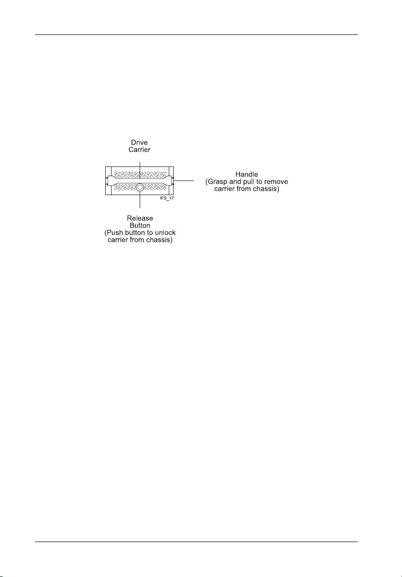
Removing a Drive Carrier (without a Drive Installed)
Remove the drive carrier by grasping carrier handle and pushing in the carrier release button
simultaneously. Pushing in the carrier release button will unlock carrier and allow removal from
the InfoStation drive bay (Figure 1 and 3).
Figure 1: Drive Carrier
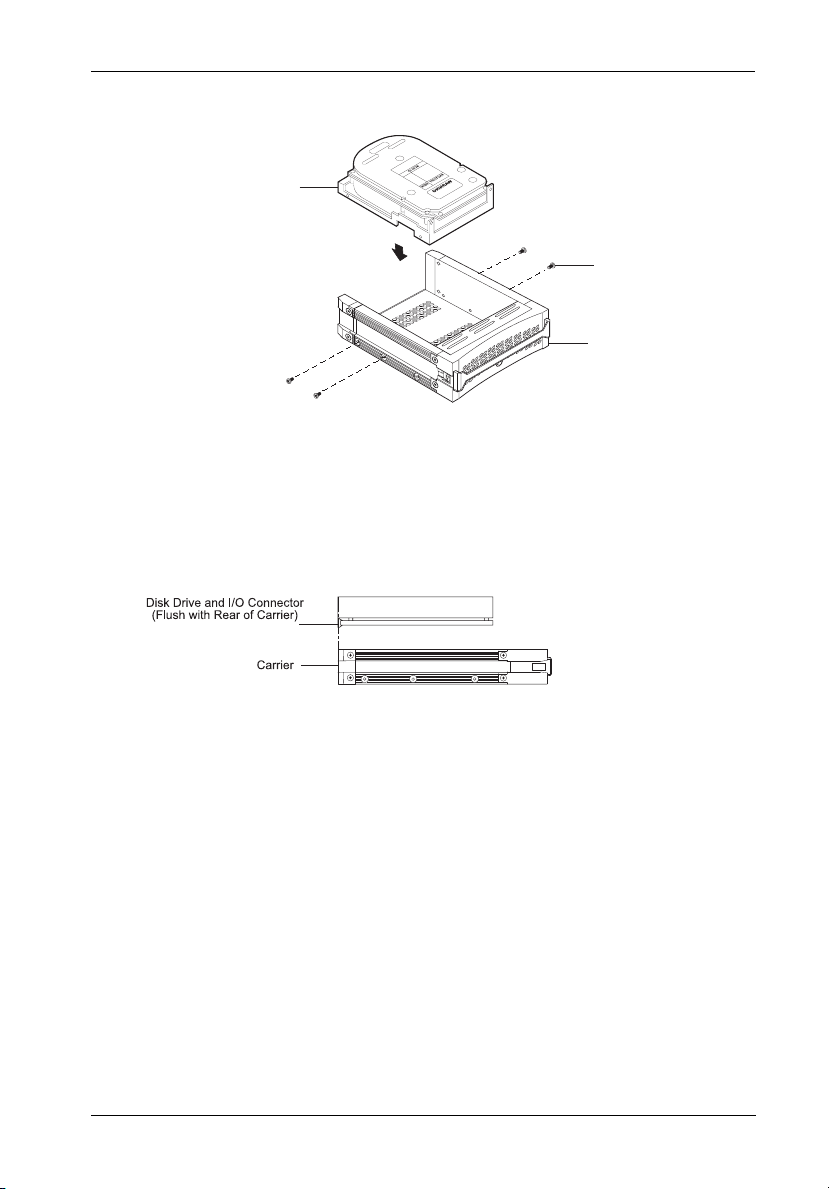
Installing a Drive into the Drive Carrier
NOTE: Before installing the drive into the carrier, the ID jumpers and spin-up option jumper
1. Install the drive(s) into the drive carrier(s). Drive(s) must be side-mounted into the
2. After the drive(s) have been installed in to the drive carrier(s), carefully insert the
StorCase Technology, Inc. InfoStation Installation Guide - Rev. C01
on the disk drive must be removed. This is required so that the InfoStation itself can
set the drive SCSI ID and spin-up option.
drive carrier(s) using #6-32 screws (Figure 2).
carrier(s) back into the chassis.
Page 8
Installation 3
Drive
(Not Included)
#6-32 Phillips Head
Mounting Screw
(4 total)
InfoStation
Drive Carrier
IFS_18
Figure 2: Drive Installation
Inserting a Drive into the Chassis
NOTE: A new drive carrier can be inserted into an empty bay at anytime. However, the
1. Press and hold the Insert/Remove button in until the Drive Ready LED starts to flash
2. Drive is ready to be accessed when the Drive Ready LED glows instead of flashes.
InfoStation Installation Guide - Rev. C01 StorCase Technology, Inc.
drive will not be ready for access until the following procedure is followed.
(approximately 3 seconds).
Page 9

4 Installation
Removing a Drive from the Chassis
(Refer to section "Drive Bay Interface Panel" in the InfoStation User's Guide for further
information)
NOTE: Proper procedure must be followed when removing a drive from the drive bay. It
is the responsibility of the User to ensure that the host does not access the drive
while attempting to remove the drive, and to follow the procedure outlined below.
Failure to do so may result in loss of data and/or damage to the drive itself!
1. Press and hold the Insert/Remove button in until the Drive Ready LED starts to flash
(approximately 3 seconds).
2. Drive is ready to be removed when the Drive Ready LED is OFF.
3. Remove the drive carrier by grasping carrier handle and pushing in the carrier
release button simultaneously. Pushing in the release button will unlock carrier and
allow removal from the InfoStation drive bay (Figures 1 and 3).
InfoStation
Chassis
IFS_19
Drive
Carrier
Figure 3: Removing the Drive Carrier
StorCase Technology, Inc. InfoStation Installation Guide - Rev. C01
Page 10

Installation 5
Removing the Blower Module
CAUTION: The blower module contains NO USER SERVICEABLE PARTS inside the
unit. Warranty is VOID if module is opened. Refer ALL servicing to
qualified service personnel!
NOTE: The blower module is hot-swappable. The chassis may remain on when
removing and installing the blower module.
1. Loosen and remove the #6-32 Phillips Pan Head screw securing the blower module
to the InfoStation chassis (Figure 4).
2. Remove the blower module by grasping handle and pulling out from chassis.
3. To reinstall blower module, simply reverse above mentioned steps.
InfoStation
Chassis
IFS_20
Blower
Module
#6-32 Phillips
Pan Head Screw
(1 total)
Figure 4: Removing the Blower Module
InfoStation Installation Guide - Rev. C01 StorCase Technology, Inc.
Page 11
6 Installation
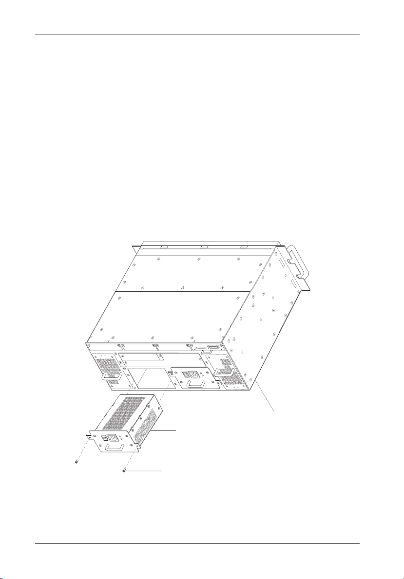
Removing the Power Supply Module
CAUTION: The power supply module contains NO USER SERVICEABLE PARTS inside
the unit. Warranty is VOID if module is opened. Refer ALL servicing to
qualified service personnel!
NOTE: The power supply module is hot-swappable. The chassis may remain on
when removing and installing the power supply module.
1. Turn OFF power to the power supply module via the Power Switch located on the
module itself.
2. Loosen and remove the two (2) #6-32 Phillips Pan Head screws securing the power
supply module to the InfoStation chassis (Figure 5).
3. Remove the power supply module by grasping handle and pulling out from chassis.
4. To reinstall power supply module, simply reverse above mentioned steps.
IFS_21
InfoStation
Power Supply
Module
#6-32 Phillips
Pan Head Screw
(2 total)
Chassis
Figure 5: Removing the Power Supply Module
StorCase Technology, Inc. InfoStation Installation Guide - Rev. C01
Page 12

Installation 7
Removing and Installing the I/O Repeater Module
CAUTION: Remove ALL power from the InfoStation before removing the I/O repeater
module. The I/O repeater module contains NO USER SERVICEABLE PARTS inside
the unit. Refer ALL servicing to qualified service personnel!
NOTE: The I/O repeater module is NOT hot-swappable! Remove ALL power to chassis
before removing and installing the I/O repeater module.
1. Unplug the InfoStation and verify that all cables have been disconnected.
2. Place the InfoStation on a soft clean surface to protect finish of the chassis.
3. Loosen and remove the two (2) #6-32 Phillips Pan Head screws securing the I/O
repeater module to the InfoStation chassis (Figure 6).
4. Remove the I/O repeater module by grasping handle and pulling out from chassis.
5. To reinstall I/O repeater module, simply reverse above mentioned steps.
IFS_22
InfoStation
Chassis
I/O Repeater
Module
#6-32 Phillips
Head Screw
(2 places)
Figure 6: Removing and Installing the I/O Repeater Module
InfoStation Installation Guide - Rev. C01 StorCase Technology, Inc.
Page 13
8 Installation
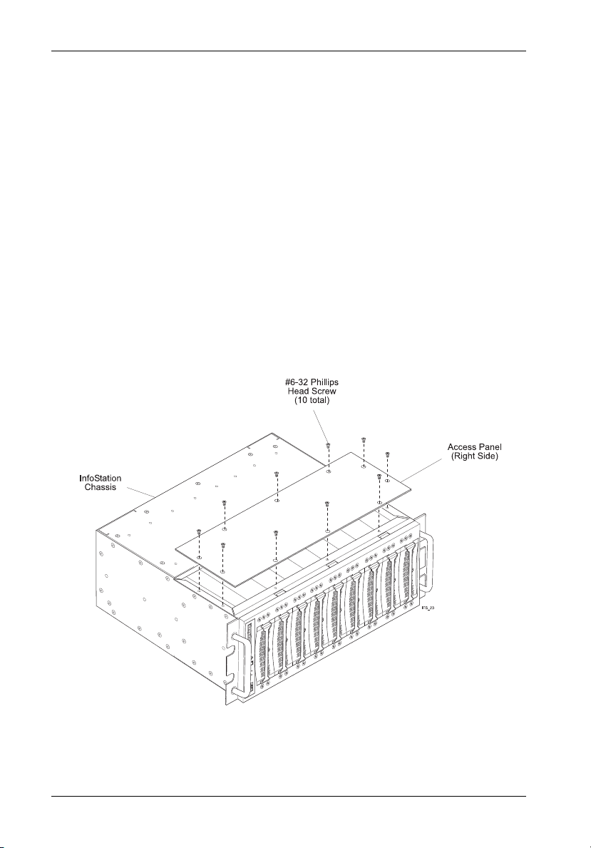
Removing the InfoStation Access Panel
CAUTION: Remove ALL power from the InfoStation before removing the access panel(s).
1. Unplug the InfoStation and verify that all cables have been disconnected.
2. Place the InfoStation on a soft clean surface to protect finish of the chassis.
3. Remove the ten (10) #6-32 Phillips Flat Head screws securing the access panel to
NOTE: Remove the access panel located on the RIGHT SIDE of the chassis only.
4. Remove the access panel by carefully lifting the panel(s) off the chassis (Figure 7).
5. To reinstall panel, simply reverse the above mentioned steps.
The InfoStation contains NO USER SERVICEABLE PARTS inside the unit.
Warranty is VOID if any of the modules inside the InfoStation are opened. Refer
ALL servicing to qualified service personnel!
the InfoStation chassis (Figure 7).
Figure 7: Removing the Access Panel
StorCase Technology, Inc. InfoStation Installation Guide - Rev. C01
Page 14

Installation 9
Figure 8 below shows the inside of the InfoStation chassis (single-channel configuration) with
the access panel removed.
Figure 8: Single-Channel Configuration
InfoStation Installation Guide - Rev. C01 StorCase Technology, Inc.
Page 15

10 Installation
Configuring the InfoStation for Dual-Channel
CAUTION: Remove ALL power from the InfoStation before removing the I/O repeater
module. The I/O repeater module contains NO USER SERVICEABLE PARTS inside
the unit. Refer ALL servicing to qualified service personnel!
1. Unplug the InfoStation and verify that all cables have been disconnected.
2. Place the InfoStation on a soft clean surface to protect finish of the chassis.
3. Loosen and remove the two (2) #6-32 Phillips Pan Head screws securing the I/O
blank plate to the InfoStation chassis (Figure 9).
4. Remove the I/O blank plate as shown in Figure 9.
5. Remove access panel (as described on page 8).
6. Remove the center jumper block so that the second I/O repeater module and terminator can be installed. Correct dual-channel configuration is shown in Figure 10.
IFS_25
I/O Repeater
Module
I/O Blank
Plate
InfoStation
#6-32 Phillips
Head Screw
(2 per Plate)
Chassis
Figure 9: Removing the I/O Blank Plate for Dual-Channel Configuration
StorCase Technology, Inc. InfoStation Installation Guide - Rev. C01
Page 16

Installation 11
Figure 10: Dual-Channel Configuration
InfoStation Installation Guide - Rev. C01 StorCase Technology, Inc.
Page 17

12 Installation
Configuring the InfoStation for 4-Channel
CAUTION: Remove ALL power from the InfoStation before removing the I/O repeater
module. The I/O repeater module contains NO USER SERVICEABLE PARTS inside
the unit. Refer ALL servicing to qualified service personnel!
1. Unplug the InfoStation and verify that all cables have been disconnected.
2. Place the InfoStation on a soft clean surface to protect finish of the chassis.
3. Loosen and remove the two (2) #6-32 Phillips Pan Head screws securing each
I/O blank plate to the InfoStation chassis (Figure 11).
4. Remove all three (3) I/O blank plates as shown in Figure 11.
5. Remove access panel (as described on page 8).
6. Remove all the jumper blocks so that I/O repeater modules ( #2, 3, and 4) and terminators (#2, 3, and 4) can be installed. Correct 4-channel configuration is shown
in Figure 12.
IFS_27
I/O Repeater
Module
I/O Blank
Plates
#6-32 Phillips
Head Screw
(2 per Plate)
InfoStation
Chassis
Figure 11: Removing the I/O Blank Plates for 4-Channel Configuration
StorCase Technology, Inc. InfoStation Installation Guide - Rev. C01
Page 18

Installation 13
Figure 12: 4-Channel Configuration
InfoStation Installation Guide - Rev. C01 StorCase Technology, Inc.
Page 19

14 Installation
RAID MODULE INSTALLATION
CAUTION: Remove ALL power from the InfoStation before installing the RAID
NOTES: The installation, configuration, and use of the RAID module option for the
Module. The RAID Module contains NO USER SERVICEABLE PARTS inside the unit. Warranty is VOID if module is opened. Refer ALL servicing to qualified service personnel!
StorCase InfoStation chassis requires a certain level of expertise and
experience on the part of the user/integrator. Since there are many configuration options and variables (ie. host platforms, applications, etc), only
general guidelines will be discussed in this Installation Guide.
Installing the RAID Module into the InfoStation
While performing the steps in this section, work on a soft surface to prevent excessive shock
to the RAID module and InfoStation chassis. Also refer to the manufacturer's documentation
provided with the drive(s). A #2 Phillips and a flat blade screwdriver will be required.
Removing the InfoStation Module Option Cover Plate
CAUTION: Remove ALL power from the InfoStation before removing any panels or cover
1. Loosen and remove the three (3) #6-32 Phillips screws securing the module option
2. Remove the remaining screw on the cover plate and disassemble into two pieces
3. To reinstall cover plate, simply reverse the above mentioned steps.
plates. The InfoStation contains NO USER SERVICEABLE PARTS inside the unit.
Refer ALL servicing to qualified service personnel!
cover plate to the InfoStation chassis (Figure 13). Remove the cover plate.
(Figure 14). Save the smaller section, it will be used later in Step 2 of "Installing the
RAID Module into the InfoStation Chassis".
StorCase Technology, Inc. InfoStation Installation Guide - Rev. C01
Page 20

Installation 15
InfoStation
Chassis
(Rear)
Module Option
Cover Plate
#6-32 Phillips
Head Screw
(3 per Plate)
IFS_43
Figure 13: Removing the Module Option Cover Plate
Module Option
Save this
Section!
#6-32 Phillips
Head Screw
(1 Place)
Cover Plate
IFS_44
Figure 14: Disassembling the Module Option Cover Plate
InfoStation Installation Guide - Rev. C01 StorCase Technology, Inc.
Page 21

16 Installation
Installing the RAID Module into the InfoStation Chassis
1. Carefully slide the RAID module into the chassis and tighten screws (Figure 15).
2. Attach the smaller section of the disassembled cover plate to the module and chassis
and secure with two (2) #6-32 Phillips Head screws (Figure 15).
DXIFS_45
InfoStation Chassis
(Rear)
DXIFS-160/RAID
Controller Module
#6-32 Phillips
Head Screw
(2 Places)
Figure 15: Installing the RAID Module into the Chassis
StorCase Technology, Inc. InfoStation Installation Guide - Rev. C01
Page 22

Installation 17
Replacing the RAID Controller Battery
CAUTION: Remove ALL power from the InfoStation before uninstalling the RAID
Module. The RAID Module contains NO USER SERVICEABLE PARTS inside
the unit (only the battery is user serviceable). Warranty is VOID if module
is opened (only the battery cover may be opened by user). Refer ALL other
servicing to qualified personnel!
Danger of explosion if the RAID battery is incorrectly replaced! Replace
only with the same or equivalent type recommended by the manufacturer.
Dispose of used batteries according to the manufacturer's instructions.
NOTE: While performing the steps in this section, work on a soft surface to pre-
vent excessive shock to the RAID module and InfoStation chassis.
1. Remove RAID module from the InfoStation chassis by simply reversing steps in section
"Installing the RAID Module into the InfoStation Chassis" (Figure 15).
2. Once module is removed, loosen and remove the two (2) screws securing the battery
cover to the module (Figure 16). Remove cover.
Remove These
Two Screws
Battery
Cover
E
/S
D
V
L
I
S
C
S
ULTRA160
IFS_72
RAID
Module
Figure 16: Removing the Battery Cover
InfoStation Installation Guide - Rev. C01 StorCase Technology, Inc.
Page 23

18 Installation
3. Once the battery cover is removed, unplug the battery cable from the RAID module
(Figure 17).
4. Carefully turn the RAID Module over to access the two (2) screws securing the battery
bracket to the module (Figure 18). Loosen and remove the screws. The bracket and
battery should now drop out when the RAID Module is lifted.
Battery
Cable
3-Cell
NiMH
Battery
IFS_74
Disconnect
Cable Here
Figure 17: Unplugging the Battery from the RAID Module
5. Replace battery and install by simply reversing the above mentioned steps. MAKE
SURE THAT THE BATTERY IS INSTALLED CORRECTLY!
CAUTION: Danger of explosion if the battery is incorrectly replaced! Replace
StorCase Technology, Inc. InfoStation Installation Guide - Rev. C01
only with the same or equivalent type recommended by the manufacturer. Dispose of used batteries according to the manufacturer's
instructions.
Page 24

Installation 19
Battery
Bracket
E
/S
D
LV
I
S
C
S
ULTRA160
3-Cell
NiMH
Battery
Remove These
Two Screws
IFS_73
Figure 18: Removing the Battery Bracket
InfoStation Installation Guide - Rev. C01 StorCase Technology, Inc.
 Loading...