

Page 1

StorCase® Technology
InfoSt ation
External SCSI
4-Bay Expansion Chassis
User's Guide
®
Page 2
StorCase® Technology
i
InfoSt ation
®
External SCSI
4-Bay Expansion Chassis
User's Guide
Part No. D89-0000-0178 C01 May 2004
StorCase Technology, Inc.
17600 Newhope Street
Phone (714) 438-1850 Fax (714) 438-1847
InfoStation 4-Bay User's Guide - Rev. C01 StorCase Technology, Inc.
Fountain Valley, CA 92708-9885
Page 3

ii
LIMITED WARRANTY
STORCASE TECHNOLOGY, Incorporated (StorCase) warrants that its products will be free
from defects in material and workmanship, subject to the conditions and limitations set forth
below. StorCase will, at its option, either repair or replace any part of its product that proves
defective by reason of improper workmanship or materials. Repair parts or replacement
products will be provided by StorCase on an exchange basis, and will be either new or
reconditioned to be functionally equivalent to new.
This warranty does not cover any product damage that results from accident, abuse, misuse,
natural or personal disaster, external power surge or failure, or any unauthorized disassembly, repair or modification. StorCase will not be responsible for any software, firmware or other
customer data stored within, or interfacing with a StorCase product.
Duration of Warranty
Seven-Year Warranty: The following StorCase products are covered by this warranty for
a period of seven (7) years from the original date of purchase from StorCase or its authorized
reseller: all Data Express® removable device enclosures and all StorCase interface cables and
accessories specifically intended for use with these products. Data Silo®, Data Stacker® and
InfoStation® products are covered by this warranty for a period of seven (7) years, excepting
the RAID controller, power supply, fan and blower components, which are covered by the
three-year warranty described below.
Three-Year Warranty: The following StorCase products are covered by this warranty for
a period of three (3) years from the original date of purchase from StorCase or its authorized
reseller: all Rhino®JR external expansion chassis, all RhinoJR removable drive enclosures,
and all RAID controller modules. In addition, the following components of the Data Express,
Data Silo, Data Stacker, InfoStation products are subject to warranty for a period of three (3)
years: all power supplies, fans and blowers.
Warranty Claim Requirements
To obtain warranty service, the defective product must be returned to your local authorized
StorCase dealer or distributor, or, with prior StorCase approval, to the StorCase factory
service center.
For defective products returned directly to StorCase, a Return Material Authorization (RMA)
number must be obtained by calling StorCase Customer Service at (714) 445-3455. The RMA
number must be prominently displayed on the outside of the return package. Shipments must
be freight-prepaid and insured, and must include the product serial number, a detailed
description of the problem experienced, and proof of the original retail purchase date. Products
must be properly packaged to prevent damage in transit. Damage resulting from improper
packaging will not be covered by this warranty. The StorCase factory service center is located
at 17650 Newhope Street, Receiving Dock, Gate #4, Fountain Valley, CA 92780, U.S.A.
StorCase Technology, Inc. InfoStation 4-Bay User's Guide - Rev. C01
Page 4

Free Technical Support
StorCase provides free technical support. If you experience any difficulty during the
installation or subsequent use of a StorCase product, please contact StorCases Technical
Support Department prior to servicing your system. This warranty covers only repair or
replacement of defective StorCase products, as described above. StorCase is not liable for,
and does not cover under warranty, any costs associated with servicing and/or installation
of StorCase products.
StorCase Technical Support can be reached in the U.S. at (714) 438-1858 or toll-free at (888)
435-5460 (U.S. and Canada only). StorCase European Technical Support can be reached in
the U.K. at +44 (0) 1932 738900.
Disclaimers
The foregoing is the complete warranty for the products identified above and
supersedes all other warranties and representations, whether oral or written.
StorCase expressly disclaims all warranties for the identified products, which are
not stated herein, including, to the extent permitted by applicable law, any implied
warranty of merchantability or fitness for a particular purpose. In no event will
StorCase be liable to the purchaser, or to any user of a StorCase product, for any
damages, expenses, lost revenues, lost savings, lost profits, or any other
incidental or consequential damages arising from the purchase, use or inability
to use a StorCase product, even if StorCase has been advised of the possibility
of such damages.
iii
Copyright © 2003 StorCase Technology. All rights reserved. All registered
trademarks are the property of StorCase Technology. All other logos and trademarks
are properties of their respective companies.
InfoStation 4-Bay User's Guide - Rev. C01 StorCase Technology, Inc.
Page 5
iv
Declaration of Conformity
Company Name:
Corporate Office Address:
Manufacturing Address:
Product Name:
Model Number:
Conforms to the following standards:
EMC Directives:
(89/336/EEC)
Low Voltage Directive:
(73/23/EEC)
Safety Standards:
CSA (NRTL/C)
TUV:
StorCase Technology, Inc.
17600 Newhope Street
Fountain Valley, CA 92708
17600 Newhope Street
Fountain Valley, CA 92708
InfoStation 4-Bay
S10A119, S10A120
ITE Emission
- EN 55022: 1998
- EN 61000-3-2 Harmonic Current
- EN 61000-3-3 Voltage Fluctuations and Flicker
EN 55024: 1998 ITE Immunity
- EN 61000-4-2 - EN 61000-4-5
- EN 61000-4-3 - EN 61000-4-6
- EN 61000-4-4 - EN 61000-4-8
- EN 61000-4-11
EN 60950
CAN/CSA-C22.2 No. 60950
UL 60950, Third Edition
EN 60950: 2000
EMI Standards:
EMC Standards:
Year of Manufacture:
Signature:___________________
Full Name: Dieter Paul
Position: President
StorCase Technology, Inc. InfoStation 4-Bay User's Guide - Rev. C01
FCC Part 15, Class B
AS/NSZ 3548 Information Technology Equipment
2002
Page 6

Federal Communications Commission (FCC) Statement
RADIO FREQUENCY INTERFERENCE STATEMENT
You are cautioned that changes or modifications not expressly approved by the party
responsible for compliance could void your authority to operate that equipment.
This device complies with part 15 of the FCC rules. Operation is subject to the following two
conditions: (1) This device may not cause harmful interference, and (2) This device must
accept any interference received, including interference that may cause undesired operation.
Important Safety Instructions
1. Read all these instructions.
2. Save these instructions for later use.
3. Follow all warnings and instructions marked on the product.
4. Do not use this product near water.
5. This product should be operated from the type of power source indicated on the
marking label. If you are not sure of the type of power available, consult your dealer
or local power company.
6. Do not attempt to service this product yourself, as opening or removing covers may
expose you to dangerous voltage points or other risk. Refer all servicing to service
personnel.
v
Wichtige Sicherheitshinweise
1. Diese Hinweise sollten vollständig durchgelesen werden.
2. Diese Hinweise für einen späteren Gebrauch aufbewahren.
3. Allen auf dem Gerät angebrachten Warnungen und Hinweisen folgen.
4. Das Gerät nicht in der Nähe von Wasser verwenden.
5. Das Gerät nur mit dem Aufkleber bezeichneten Netzspannung betreiben. Bei Fragen
über die Art der Netzspannung sollte der Händler oder das
Energieversorgungsunternehmen zu rate gezogen werden.
6. Nicht versuchen das Produkt selbst zu reparieren. In allen Produkten existieren
gefährliche elektrische Spannugen. Nicht das Gehäuse öffnen.
7. Wartungsarbeiten nur von qualifiziertern Kundendienstpersonal ausführen laßen.
InfoStation 4-Bay User's Guide - Rev. C01 StorCase Technology, Inc.
Page 7

vi
Table of Contents
INTRODUCTION ..................................................................................................................... 1
Packaging Information .................................................................................................. 1
Serial Number ................................................................................................................ 1
General Description ...................................................................................................... 2
Front Panel ............................................................................................................ 3
Rear Panel ............................................................................................................. 5
INSTALLATION ...................................................................................................................... 7
Installing the Drive(s) into the InfoStation ................................................................... 7
Drive Preparation .................................................................................................. 7
Inserting a Drive Carrier (without a Drive Installed) ........................................... 8
Drive Bay Interface Panel .................................................................................... 8
Installing a Drive into the Drive Carrier .............................................................. 10
Inserting a Drive into the Chassis ..................................................................... 10
Removing a Drive from the Chassis .................................................................. 11
Selecting the SCSI ID Number .................................................................................... 12
Removing and Installing the SCSI I/O Module ............................................................ 13
Typical SCSI Channel Configurations........................................................................ 14
Single-Channel InfoStation................................................................................. 14
Dual-Channel InfoStation ................................................................................... 16
APPENDICES ........................................................................................................................ 17
Appendix A - Specifications/Dimensions .................................................................. 18
Appendix B - Optional Accessories......................................................................... 21
SCSI I/O Repeater Modules ................................................................................ 21
SCSI Terminator Board ....................................................................................... 22
SAF-TE Processor Board .................................................................................. 23
Replacement Blower .......................................................................................... 24
Drive Carrier ........................................................................................................ 25
Carrying Case ..................................................................................................... 26
Reader's Comments............................................................................................................ 27
StorCase Technology, Inc. InfoStation 4-Bay User's Guide - Rev. C01
Page 8

List of Figures
Figure 1: InfoStation 4-Bay ............................................................................................ 2
Figure 2: InfoStation Front Panel ................................................................................... 4
Figure 3: InfoStation Rear Panel .................................................................................... 6
Figure 4: Drive Carrier ................................................................................................... 8
Figure 5: InfoStation Drive Bay Interface Panel ........................................................... 9
Figure 6: Drive Installation ........................................................................................... 10
Figure 7: Removing the Drive Carrier........................................................................... 11
Figure 8: SCSI ID Selection Switches ......................................................................... 12
Figure 9: Removing and Installing the I/O Module ........................................................ 13
Figure 10: Typical Single SCSI Host Connection to InfoStation ..................................... 14
Figure 11: Typical Single SCSI Host Connection to InfoStation ..................................... 15
Figure 12: Typical Dual SCSI Host Connection to InfoStation ....................................... 16
Figure 13: Typical Dual SCSI Host Connection to InfoStation ....................................... 16
Figure A-1: InfoStation 4-Bay Physical Dimensions ...................................................... 20
Figure B-1: SCSI I/O Repeater Module ............................................................................ 21
Figure B-2: Terminator Board .......................................................................................... 22
Figure B-3: SAF-TE Processor Board ............................................................................ 23
Figure B-4: Blower .......................................................................................................... 24
Figure B-5: Drive Carrier ................................................................................................. 25
Figure B-6: Carrying Case ............................................................................................... 26
vii
List of Tables
Table 1: Drive Bay Interface Components ...................................................................... 10
NOTICE: This User's Guide is subject to periodic updates without notice. While reason-
InfoStation 4-Bay User's Guide - Rev. C01 StorCase Technology, Inc.
able efforts have been made to ensure accuracy of this document, Storcase
Technology, Inc. assumes no liability resulting from errors or omissions in this
publication, or from the use of the information contained herein.
Please check the StorCase web site at http://www.storcase.com or contact
your StorCase representative for the latest revision of this document.
Page 9

Introduction 1
INTRODUCTION
PackagingInformation
The StorCase Technology InfoStation external expansion chassis is shipped in a container
designed to provide protection and prevent damage during shipment, as confirmed by the
International Safe Transit Association (ISTA Procedure 1A). The InfoStation was carefully
inspected before and during the packing procedure at the factory. Evidence of any damage
to the InfoStation should be reported to the shipper immediately.
If the wrong InfoStation model has been received, please call your reseller or StorCase at
(800) 435-0642 to arrange for a Return Material Authorization (RMA). StorCase cannot accept
returns which do not display an RMA number on the outside of the package. Return the unit
with all the original packing materials.
Before removing any component from its packaging, discharge any static electricity by
touching a properly grounded metal object.
Serial Number
The InfoStation is labeled with a serial number. This number must be reported to the StorCase
Customer Service Representative in order to receive a Return Material Authorization (RMA)
for warranty claims. Locate the serial number label and record the number in the space
provided below.
InfoStation Serial Number:
InfoStation 4-Bay User's Guide - Rev. C01 StorCase Technology, Inc.
Page 10
2 Introduction
GeneralDescription
CAUTION: The InfoStation contains NO USER SERVICEABLE parts inside the unit. Refer
ALL servicing to qualified service personnel!
VHDCI connectors are easily damaged by improper handling. Visually inspect
each connector for bent contacts and carefully align prior to insertion.
NOTES: The installation, configuration, and use of the StorCase InfoStation chassis
requires a certain level of expertise and experience on the part of the user/
integrator. Since there are many configuration options and variables (ie. host
platforms, applications, etc), only general/typical configuration guidelines will
be discussed in this User's Guide.
Daisy-chaining requires the optional SCSI I/O Repeater Module(s). Refer to
Appendix B for further information.
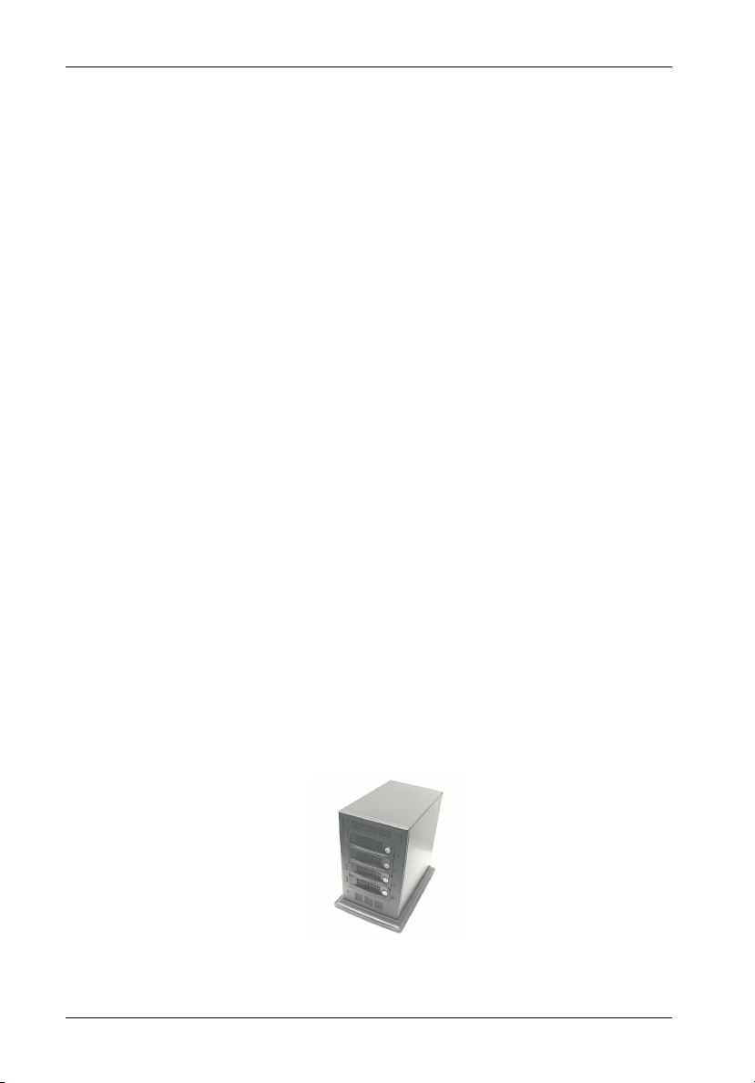
The StorCase® Technology InfoStation® 4-bay expansion chassis is designed to support
the latest high-density, high-speed SCSI disk drive technologies. The InfoStation is designed to support 3.5" form factor, half-height (up to 1.6" high) SCSI Ultra320 devices.
The InfoStation's dual backplane design can accommodate up to four (4) half-height, singleconnect SCA SCSI devices (Figure 1). Each chassis is constructed of rugged steel, lightweight
aluminum and plastic, and is equipped with one (1) 250W auto-switching power supply and
one (1) high-pressure, self-adjusting blower (39.5 CFM).
The InfoStation SCSI backplane comes standard with one (1) or two (2) Ultra320 channel
interfaces. InfoStation can also be uniquely daisy-chained for Ultra1320 operation (optional
Ultra320 I/O repeater modules are required), supporting up to fifteen (15) devices per channel
(refer to Appendix B for further information on optional InfoStation accessories).
A SAF-TE Processor Board (factory-installed) is also available as an InfoStation upgrade
option. Refer to Appendix B for further information on optional InfoStation accessories.
IFS4_8
Figure 1: InfoStation 4-Bay
StorCase Technology, Inc. InfoStation 4-Bay User's Guide - Rev. C01
Page 11

Introduction 3
This User's Guide describes the steps required for installing drive(s) into the InfoStation
external expansion chassis. This guide is intended to supplement documentation provided with
the host computer system, the operating system, and the drive(s) to be installed within the
InfoStation.
Features:
Compact enclosure (ideal for desktop applications)
Four (4) removable half-height SCA drive carriers
SCSI Ultra320 drive support
Available in Single or Dual-Channel configuration
Corrosion-resistant steel construction
One (1) high pressure, self-adjusting variable-speed blower (39.5 CFM)
One (1) 250W auto-ranging power supply
Audible alarm
Status indicators at each bay
Optional SCSI I/O Repeater Modules available
Optional SAF-TE Processor Board (factory-installed) available
7-year warranty and free 24/7 technical support
FrontPanel
(Figure 2)
Filler Panel - Allows the installation of future StorCase upgrade products.
LED(s) - Provide the following information:
Drive Ready - Indicates that the drive is properly installed and ready for ac-
Drive Activity - Indicates that the drive is being accessed.
Drive Fault - Indicates a drive failure.
InfoStation 4-Bay User's Guide - Rev. C01 StorCase Technology, Inc.
cess.
Page 12

4 Introduction
Power Supply LED -
Green - Steady glow indicates normal power supply operation.
No glow indicates no A/C power.
Amber - Indicates undervoltage (DC power) conditions or abnormal DC voltage
range.
Drive Carrier(s) - Accommodate up to four (4) 3.5" half-height single-connect SCA
devices. Backplane design with direct-connect SCA connectors eliminates cable
connections to SCSI drives, increases data integrity, and supports drive hot swappability.
Key Lock(s) - Prevent unauthorized removal or installation of the carrier(s).
NOTE: The key lock is only to prevent unauthorized removal or installation of the
drive carrier. Locking the key lock is not required for drive carrier operation.
Insert/Remove Push Button(s) - Allow the drive carriers to be removed and
installed at anytime (refer to sections "Inserting a Drive into the Chassis" and "Re-
moving a Drive from the Chassis" for further information).
Filler Panel
LEDs
Drive Ready
Drive Activity
Drive Fault
Drive Carrier
Key Lock
Carrier Handle
Insert/Remove
Power
Supply LED
IFS4_9
Push Button
Figure 2: InfoStation Front Panel
StorCase Technology, Inc. InfoStation 4-Bay User's Guide - Rev. C01
Page 13

Introduction 5
RearPanel
(Figure 3)
SCSI ID Select Switch(es) - Provide SCSI ID selection for each drive bay (4 total).
The InfoStation uses four (4) rotating switches (refer to section "Selecting the SCSI
ID Number" for further information).
Fault LED -
OFF - Indicates normal temperature and fan conditions.
Red - Slow blink indicates overtemperature conditions. Audible alarm
Alarm Mute Switch - Mutes audible alarm.
Alarm Mute LED -
OFF - Indicates that alarm is enabled (audible alarm will sound).
Amber - Indicates that alarm is muted (audible alarm will not sound).
Reset Switch - Resets controller module (will not reset the SCSI bus).
SCSI I/O Module(s) - Available with single or dual 68-pin VHDCI connectors for
single or dual-channel Ultra320 configurations.
NOTE: Daisy-chaining requires the optional SCSI I/O Repeater Module(s). Refer
to Appendix B for further information.
Power Switch - Rocker switch controls power to the power supply.
will also sound (if enabled).
Fast blink indicates both overtemperature and fan failure conditions. Audible alarm will also sound (if enabled).
Steady glow indicates fan failure. Audible alarm will also sound
(if enabled).
A/C Power In - Accepts U.S. and other available international standard power
cables.
Blower Vent - High-pressure blower inside provides ample cooling (39.5 CFM) for
high speed drives. Self-adjusting variable-speed blower for optimal cooling
performance.
Power Supply (Not Shown) - One (1) 250W auto-switching power supply.
InfoStation 4-Bay User's Guide - Rev. C01 StorCase Technology, Inc.
Page 14

6 Introduction
SCSI ID
Select
Alarm Mute
Switch
Alarm Mute
LED
Power Switch
A/C Power In
Switches
IFS4_10
Reset Switch
Fault LED
Ultra320
I/O Module
Blower Vent
Ultra320
I/O Module
Figure 3: InfoStation Rear Panel
(with SCSI I/O Modules Installed)
StorCase Technology, Inc. InfoStation 4-Bay User's Guide - Rev. C01
Page 15

Installation 7
INSTALLATION
CAUTION: The InfoStation contains NO USER SERVICEABLE PARTS inside the unit.
NOTES: Before removing any component from its packaging, discharge any static
Warranty is VOID if any of the modules inside the InfoStation are opened.
Refer ALL servicing to qualified service personnel!
electricity by touching a properly grounded metal object.
Daisy-chaining requires the optional SCSI I/O Repeater Module(s). Refer to
Appendix B for further information.
Installing the Drive(s) into the InfoStation
While performing the steps in this section, work on a soft surface to prevent excessive shock
to the drive(s) being installed. Also refer to the manufacturer's documentation provided with
the drive(s).
Drive Preparation
1. Remove the drive from its protective packaging.
2. SCSI Drive Termination - Disable SCSI termination from the drive. Refer to the
documentation provided by the drive manufacturer for the location of these terminators or jumpers.
Refer to section "Typical SCSI Channel Configurations" for further information.
InfoStation 4-Bay User's Guide - Rev. C01 StorCase Technology, Inc.
Page 16

8 Installation
Inserting a Drive Carrier (without a Drive Installed)
Lift the carrier handle while inserting drive carrier into chassis. Push down on carrier handle
once carrier is pushed all the way in. The carrier should latch into place if inserted correctly.
Lock the key lock to prevent unauthorized removal or installation of drive carrier (locking the
key lock is not required for drive carrier operation).
Key
Lock
Carrier
Handle
IFS4_2
Figure 4: Drive Carrier
Drive Bay Interface Panel
Each InfoStation drive bay provides a User interface for individual bay operation (Figure 5).
Drive Bay
Drive Ready LED
Drive Activity LED
Insert/Remove
Drive Fault LED
Figure 5: InfoStation Drive Bay Interface Panel
StorCase Technology, Inc. InfoStation 4-Bay User's Guide - Rev. C01
Push Button
Page 17

Installation 9
The Drive Bay Interface Panel consists of the following indicators and buttons (Table 1):
Table 1: Drive Bay Interface Components
Drive Ready LED
Drive Activity LED
Drive Fault LED
Insert/Remove
Push Button
Steady glow indicates that drive is inserted
and ready for access.
Flashing indicates that drive is inserted and
in the process of being powered up.
Steady glow indicates drive is being accessed.
Steady glow indicates drive failure.
Used to put the drive in Online (insert) or
Offline (remove) mode.
InfoStation 4-Bay User's Guide - Rev. C01 StorCase Technology, Inc.
Page 18

10 Installation
Installing a Drive into the Drive Carrier
NOTES: Before installing the drive into the carrier, the ID jumpers and spin-up option
jumper on the disk drive must be removed. This is required so that the InfoStation
itself can set the drive SCSI ID and spin-up option.
A #2 Phillips screwdriver will be required for this procedure.
1. Install the drive(s) into the drive carrier(s). Drive(s) must be side-mounted into the
drive carrier(s) using #6-32 Phillips Pan Hd. screws (Figure 6).
2. After the drive(s) have been installed in to the drive carrier(s), carefully insert the
carrier(s) back into the chassis (refer to section "Inserting a Drive into the Chassis"
for further information).
Ultra320
SCA Drive
(Not Included)
IFS4_1
Drive
Carrier
#6-32 Phillips
Pan Hd. Screw
(2 on each side)
Figure 6: Drive Installation
Inserting a Drive into the Chassis
NOTES: A new drive can be inserted into an empty bay at anytime. However, the drive
1. Press and hold the Insert/Remove button (Figure 5) in until the Drive Ready LED
2. Drive is ready to be accessed when the Drive Ready LED glows instead of flashes.
StorCase Technology, Inc. InfoStation 4-Bay User's Guide - Rev. C01
will not be ready for access until the following procedure is followed.
The key lock is only to prevent unauthorized removal or installation of the drive
carrier. Locking the key lock is not required for drive carrier operation.
starts to flash (approximately 3 seconds).
Page 19

Installation 11
Removing a Drive from the Chassis
NOTE: Proper procedure must be followed when removing a drive from the drive bay.
It is the responsibility of the User to ensure that the host does not access the
drive while attempting to remove the drive, and to follow the procedure outlined
below. Failure to do so may result in loss of data and/or damage to the drive
itself!
1. Press and hold the Insert/Remove button (Figure 5) in until the Drive Ready LED
starts to flash (approximately 3 seconds).
2. Drive is ready to be removed when the Drive Ready LED is OFF.
3. Unlock the key lock (if locked) and remove the drive carrier by pulling on carrier handle
(Figures 4 & 7).
Lift Handle
and Pull to
Remove Carrier
from Chassis
IFS4_7
Figure 7: Removing the Drive Carrier
InfoStation 4-Bay User's Guide - Rev. C01 StorCase Technology, Inc.
Page 20

12 Installation
Selecting the SCSI ID Number
NOTE: The InfoStation needs to be powered DOWN/UP for any SCSI ID changes to
take effect.
The SCSI ID is an address number (0-7 for 8-bit protocol and 0-15 for 16-bit protocol) that is
assigned to each SCSI device. Each device in the chain must have a unique SCSI ID number.
SCSI ID 7 is usually reserved for the host controller. If the computer system is already equipped
with internal or external SCSI storage devices, some ID numbers will already be reserved. For
instance, if the computer system came with an internal SCSI hard drive, it may be designated
as SCSI device 0 (refer to the computer system documentation for additional information).
Four (4) SCSI ID selection switches are located on the rear panel of the InfoStation enclosure
(Figures 3 & 8). These rotating switches can be adjusted with the provided alignment tool.
Carefully select the appropriate SCSI ID number(s) for the installed device(s). Note that some
switch settings may be invalid for your interface type. Selecting an invalid ID number, or
selecting the same number on different devices may cause unpredictable results and the
computer system may not recognize the installed device(s). If the computer system can not
recognize the boot disk, the computer system may fail to properly start-up.
BAY 1 BAY 2 BAY 3 BAY 4
Some SCSI unit ID numbers on the selection switches may be invalid for your interface type.
Valid 8-bit ID numbers include 0-7. Valid 16-bit ID numbers include 0-15 (Do not use ID7. It
is usually reserved for the host.) Refer to your drive manufacturers documentation for further
information.
0636c
Figure 8: SCSI ID Selection Switches
StorCase Technology, Inc. InfoStation 4-Bay User's Guide - Rev. C01
Page 21

Installation 13
NOTES: Each bay has a factory default SCSI ID as follows:
Bay 1 = SCSI ID 0 Bay 3 = SCSI ID 2
Bay 2 = SCSI ID 1 Bay 4 = SCSI ID 3
Factory default SAF-TE Processor Board SCSI ID (if factory-installed) is
15.
Removing and Installing the SCSI I/O Module
(Procedure and information below applies to both the SCSI I/O Module and the optional SCSI
I/O Repeater Modules)
CAUTION: Remove ALL power from the InfoStation before removing and/or installing
the SCSI I/O module. The SCSI I/O module contains NO USER SERVICE
ABLE PARTS inside the unit. Refer ALL servicing to qualified service
personnel!
VHDCI connectors are easily damaged by improper handling. Visually
inspect each connector for bent contacts and carefully align prior to
insertion.
NOTES: The SCSI I/O module is NOT hot-swappable! Remove ALL power to
chassis before removing and installing the SCSI I/O module.
An optional SCSI I/O Repeater Module is available as an upgrade. Contact
StorCase for further information.
1. Unplug the InfoStation and verify that ALL cables have been disconnected.
2. Place the InfoStation on a soft clean surface to protect finish of the chassis.
3. Loosen and remove the two (2) #6-32 Phillips Flat Hd. screws securing the SCSI
I/O module to the InfoStation chassis (Figure 9).
4. Remove the SCSI I/O module by grasping handle and pulling out from chassis.
5. To install SCSI I/O module, simply reverse above mentioned steps.
I/O Module
#6-32 Phillips
F.H. Screw
(2 Total)
Figure 9: Removing and Installing the SCSI I/O Module
InfoStation 4-Bay User's Guide - Rev. C01 StorCase Technology, Inc.
Page 22

14 Installation
Typical SCSI Channel Configurations
CAUTION: When using the double-stacked VHDCI connectors simultaneously, offset
VHDCI cable connectors must be used for proper fit. Failure to use proper
cables may result in damage to the InfoStation VHDCI connectors!
VHDCI connectors are easily damaged by improper handling. Visually inspect
each connector for bent contacts and carefully align prior to insertion.
NOTES: Daisy-chaining requires the optional SCSI I/O Repeater Module(s). Refer to
Appendix B for further information.
Up to fifteen (15) drives maximum per SCSI channel.
The InfoStation scalable backplane design allows either a single or dual-channel configuration.
Single-Channel InfoStation
Single-channel InfoStations must be externally terminated (terminator not included) as shown
in Figures 10 & 11.
SCSI Host
PC
T
= Terminator
T
InfoStation 4-Bay
Chassis
Figure 10: Typical Single SCSI Host Connection to InfoStation
(Single-Channel InfoStation with SCSI I/O Modules Installed)
StorCase Technology, Inc. InfoStation 4-Bay User's Guide - Rev. C01
IFS4_11
Page 23

Installation 15
PC
= Terminator
T
SCSI Host
T
InfoStation 4-Bay
Chassis
Terminate or Cascade
to Another InfoStation
NOTE: Optional Terminator
IFS4_18
Board is available.
Refer to Appendix B
for further information.
Figure 11: Typical Single SCSI Host Connection to InfoStation
(Single-Channel InfoStation with Optional SCSI I/O Repeater Module Installed)
InfoStation 4-Bay User's Guide - Rev. C01 StorCase Technology, Inc.
Page 24

16 Installation
Dual-Channel InfoStation
SCSI Host A
PC
InfoStation 4-Bay
Chassis
SCSI Host B
Figure 12: Typical Dual SCSI Host Connection to InfoStation
(Dual-Channel InfoStation with SCSI I/O Modules Installed)
SCSI Host A
PC
Terminate or Cascade
to Another InfoStation
InfoStation 4-Bay
Chassis
SCSI Host B
PC
Terminate or Cascade
to Another InfoStation
PC
IFS4_13
IFS4_12
(Dual-Channel InfoStation with Optional SCSI I/O Repeater Modules Installed)
Figure 13: Typical Dual SCSI Host Connection to InfoStation
StorCase Technology, Inc. InfoStation 4-Bay User's Guide - Rev. C01
Page 25

Appendix A - Specifications/Dimensions 17
APPENDICES
InfoStation 4-Bay User's Guide - Rev. C01 StorCase Technology, Inc.
Page 26

18 Appendix A - Specifications/Dimensions
Appendix A - Specifications/Dimensions
The following InfoStation 4-bay specifications and dimensions are provided for reference only.
Environmental Specifications
Operating
Ambient Temperature 0° C to 35° C -40° C to 70° C
Relative Humidity
Altitude
(2)
Shock
(1)
Non-condensing with maximum gradient of 10% per hour
(2)
11 msec pulse width 1/2 sine wave
(1)
10% to 80% 10% to 90%
-1000 to 10,000 ft -1000 to 40,000 ft
-305m to 3048m -305m to 12195m
10g 60g
Storage
Physical
Specifications
Height
Width
Depth 13.21" (335.5mm)
Weight
(1)
Measured at the base
(2)
Weight of empty chassis (no drives installed)
11.94" (303.3mm)
8.70" (221.0mm)
(2)
26 lbs
Chassis Reliability/Maintainability
MTBF (at 25 C)
300,000 Hours
(1)
(1)
Electrical
Specifications
AC Input
DC Output
Cooling (1 Blower)
Air Flow
Noise Level
RPM
250W Power Supply
100 to 240VAC, 50/60 Hz
5V at 15A, 12V at 15A
39 CFM
51-56.5 dB-A
3100 RPM
StorCase Technology, Inc. InfoStation 4-Bay User's Guide - Rev. C01
Page 27

Appendix A - Specifications/Dimensions 19
StorCase InfoStation
SCSI Ultra320 Tower Enclosure
4 Bay
# of BaySupported 4
# of Drive Carriers Included 4
Max. # of Drives Supported 4
Max. Storage Capacity 292GB
(Based on 73GB Drives)
SCSI ID Setting Manual Config
Hot Swappable Carriers Yes
LED Status Indicators Yes
Interface SCA
SCSI Protocol LVD/SE Ultra320
Transfer Rate 320MB/sec
# of Power Supplies 1
# of Cooling Blowers 1
Speed-Variable Auto
Blowers/Fans 1 Blower (39 CFM)
# of I/O Modules 1 or 2
Max. # of Configurable 2
I/O Channels
Audible Alarm Yes
Technical Support Toll-Free
Warranty 7 Years
Regulatory Approvals
EMI FCC/CE/C-tick
Safety Agency CSA/CSA US/TUV
InfoStation 4-Bay User's Guide - Rev. C01 StorCase Technology, Inc.
Page 28

20 Appendix A - Specifications/Dimensions
6.90
(175.3mm)
8.70
(221.0mm)
11.41
(289.8mm)
11.94
(303.3mm)
Top View
Right Side ViewFront View
(335.5mm)
13.21
Figure A-1: InfoStation 4-Bay Physical Dimensions
(Dimensions are for reference only)
StorCase Technology, Inc. InfoStation 4-Bay User's Guide - Rev. C01
Page 29

Appendix B - Optional Accessories 21
Appendix B - Optional Accessories
SCSI I/O Repeater Modules
NOTE: Daisy-chaining requires the optional SCSI I/O Repeater Module(s).
Optional Ultra160 and Ultra320 I/O repeater modules (P/Ns S10A121 & S10A118) are available
to upgrade the InfoStation 4-Bay for cascading to another InfoStation chassis or other SCSI
devices as shown in Figure B-1. Each repeater module comes with dual VHDCI I/Os for dual
channel configurability. Contact StorCase for further ordering information.
IFS4_14
Figure B-1: SCSI I/O Repeater Module
InfoStation 4-Bay User's Guide - Rev. C01 StorCase Technology, Inc.
(P/N S10A121 shown)
Page 30

22 Appendix B - Optional Accessories
SCSI Terminator Board
Optional SCSI terminator boards (P/N S10A129) are available to upgrade the InfoStation 4-Bay
as shown in Figure B-2. These terminator boards offer a low cost alternative to external
terminators. Contact StorCase for further ordering information.
IFS4_15
Figure B-2: Terminator Board
StorCase Technology, Inc. InfoStation 4-Bay User's Guide - Rev. C01
Page 31

Appendix B - Optional Accessories 23
SAF-TE Processor Board
The SAF-TE Processor Board (P/N S10A159) is an optional factory-installed upgrade for the
InfoStation as shown in Figure B-3. Contact StorCase for further ordering information.
Features include:
- Monitors status of blower, power supply, and bays
- Monitors all five (5) chassis temperature sensors
- Dedicated, user-selectable SCSI ID
- Supports multi-mode (LVD/S.E.) SCSI bus communication
- SAFTEmon® management software included
- Fully compliant with SAF-TE Specification Rev. 1.0
IFS_75
Figure B-3: SAF-TE Processor Board
InfoStation 4-Bay User's Guide - Rev. C01 StorCase Technology, Inc.
Page 32

24 Appendix B - Optional Accessories
Replacement Blower
CAUTION: The blower contains NO USER SERVICEABLE PARTS inside the unit. Refer
ALL servicing to qualified service personnel!
A replacement blower is available for the InfoStation 4-Bay as shown in Figure B-4. Contact
StorCase for further ordering information.
IFS4_16
Figure B-4: Blower
StorCase Technology, Inc. InfoStation 4-Bay User's Guide - Rev. C01
Page 33

Appendix B - Optional Accessories 25
Drive Carrier
Spare drive carriers (P/N S10A108) are available for the InfoStation as shown in Figure
B-5. Contact StorCase for further ordering information.
IFS4_17
Figure B-5: Drive Carrier
InfoStation 4-Bay User's Guide - Rev. C01 StorCase Technology, Inc.
Page 34

26 Appendix B - Optional Accessories
Carrying Case
The optional molded plastic carrying case (P/N S20E104) is designed to transport the InfoStation drive carrier from one site to another in a safe, impact and moisture resistant
environment as shown in Figure B-6. Its compact dimensions, 7" long x 9" wide x 4" high, make
it easy to carry and store. The foam lining is contoured to fit a single InfoStation carrier. Contact
your StorCase dealer for further details and ordering information.
320FW_13
Figure B-6: Carrying Case
StorCase Technology, Inc. InfoStation 4-Bay User's Guide - Rev. C01
Page 35

Reader's Comments 27
Reader's Comments
Please take a few moments when your computer system is up and running to send us your
ideas and suggestions for improving our products and documentation. Did the installation go
smoothly for you? Are there any changes you would like us to make, either with the hardware
itself, or with the installation instructions? Everyone at StorCase Technology is working
toward the goal of providing you with the highest quality, most cost effective, products
available on the market, and we need your comments to guide our efforts. We look forward
to hearing from you soon!
Date:
Your Name:
Address:
Telephone: ( )
To mail this page, carefully remove it from the manual, fold it, staple or tape it shut, and drop
it in the mail. To FAX this page, carefully remove it from the manual (or make a photocopy) and
FAX it to us at (714) 438-1847. Thank you for taking the time to help us make our products
better!
InfoStation 4-Bay User's Guide - Rev. C01 StorCase Technology, Inc.
Page 36

28 Reader's Comments
FOLD ALONG THIS LINE AND STAPLE SHUT
NO POSTAGE
NECESSARY
IF MAILED
IN THE
UNITED STATES
CUT ALONG THIS LINE FROM BOTTOM TO TOP OF PAGE
BUSINESS REPLY MAIL
FIRST CLASS MAIL PERMIT NO. 10686 SANTA ANA, CA
POSTAGE WILL BE PAID BY ADDRESSEE
TECHNOLOGY CORPORATION
17600 NEWHOPE STREET
FOUNTAIN VALLEY CA 92708-9885
StorCase Technology, Inc. InfoStation 4-Bay User's Guide - Rev. C01
 Loading...