

Page 1

InfoStation LAN Management 1
StorCase® Technology
InfoSt ation
®
LAN Management Utility
for the InfoStation 16-Bay
3U SATA RAID Enclosure
User's Guide
Part No. D89-0000-0299 Rev. A01 November 2005
StorCase Technology, Inc.
17600 Newhope Street
Fountain Valley, CA 92708-9885
Phone (714) 438-1850 Fax (714) 438-1847
D89-0000-0299 Rev. A01 StorCase Technology, Inc.
Page 2

2 InfoStation LAN Management
Table of Contents
GENERAL DESCRIPTION .......................................................................................................... 5
System Requirements ..................................................................................................... 5
INSTALLATION ......................................................................................................................... 6
LAN Cable Connection .................................................................................................... 6
LAN MANAGEMENT ................................................................................................................. 7
Set-Up .............................................................................................................................. 7
Basic LAN Configuration....................................................................................... 10
Advanced LAN Configuration ............................................................................... 11
Basic Serial Configuration ............................................................................................. 12
Advanced Serial Configuration ..................................................................................... 13
System Status ................................................................................................................ 14
System Time................................................................................................................... 15
System View Log .......................................................................................................... 16
System Default............................................................................................................... 17
Changing Adminstrator Password ............................................................................... 18
System Upgrade ............................................................................................................ 19
Downloading Configuration........................................................................................... 20
Restoring Configuration................................................................................................. 20
Adding User Access Rights ......................................................................................... 21
Help ................................................................................................................................22
Logout ............................................................................................................................ 23
ENCLOSURE MANAGEMENT ................................................................................................. 24
RAID MANAGEMENT.............................................................................................................. 25
Set-Up ............................................................................................................................ 25
StorCase Technology, Inc. D89-0000-0299 Rev. A01
Page 3

InfoStation LAN Management 3
List of Figures
Figure 1: InfoStation LAN Cable Installation ...................................................................... 6
Figure 2: Login..................................................................................................................... 7
Figure 3: LAN Management Start Screen.......................................................................... 8
Figure 4: LAN Management Home Screen ........................................................................ 9
Figure 5: Basic Network Configuration Screen .............................................................. 10
Figure 6: Advanced Network Configuration Screen ...................................................... 11
Figure 7: Basic Serial Port Configuration Screen ........................................................... 12
Figure 8: Advanced Serial Port Configuration Screen .................................................... 13
Figure 9: System Status Screen ...................................................................................... 14
Figure 10: System Time Screen ......................................................................................... 15
Figure 11: System View Log .............................................................................................. 16
Figure 12: System Default .................................................................................................. 17
Figure 13: Admin Password Change Screen .................................................................... 18
Figure 14: System Upgrade Screen ................................................................................... 19
Figure 15: Add User Screen .............................................................................................. 21
Figure 16: Help Screen ....................................................................................................... 22
Figure 17: Logout Screen ................................................................................................... 23
Figure 18: InfoMon Main Screen ........................................................................................ 24
Figure 19: SCRAIDMGMT Box............................................................................................. 25
Figure 20A: Login Screen ..................................................................................................... 26
Figure 20B: Command Screen .............................................................................................. 26
Figure 20C: Minicom Screen ................................................................................................. 27
Figure 20D: RAID Configuration Menu Screen ..................................................................... 27
Figure 20E: Help Screen ....................................................................................................... 28
D89-0000-0299 Rev. A01 StorCase Technology, Inc.
Page 4

4 InfoStation LAN Management
NOTICE: This User's Guide is subject to periodic updates without notice. While reason-
able efforts have been made to ensure accuracy of this document, StorCase
Technology, Inc. assumes no liability resulting from errors or omissions in this
publication, or from the use of the information contained herein.
Please check the StorCase web site at http://www.storcase.com or contact
yourStorCase representative for the latest revision of this document.
StorCase Technology, Inc. D89-0000-0299 Rev. A01
Page 5

InfoStation LAN Management 5
GENERAL DESCRIPTION
The InfoStation LAN Management Utility allows the user to connect the InfoS t ation 16-Bay 3U
chassis to a network, allowing enclosure monitoring and configuration via LAN.
The InfoStation LAN Management Utility consists of three (3) parts:
• LAN Management - LAN set-up by network administrator
• Enclosure Management - Enclosure monitoring via LAN
• RAID Configuration - Setting up RAID configuration via LAN
System Requirements
For InfoStation LAN management, the computer system must meet the following requirements:
Internet Connection: Required only if monitoring via the web
Internet Browser: Microsoft® Internet Explorer® 5.0 (or higher) or
Mozilla® Firefox® (or other web browser)
D89-0000-0299 Rev. A01 StorCase Technology, Inc.
Page 6
6 InfoStation LAN Management
INSTALLATION
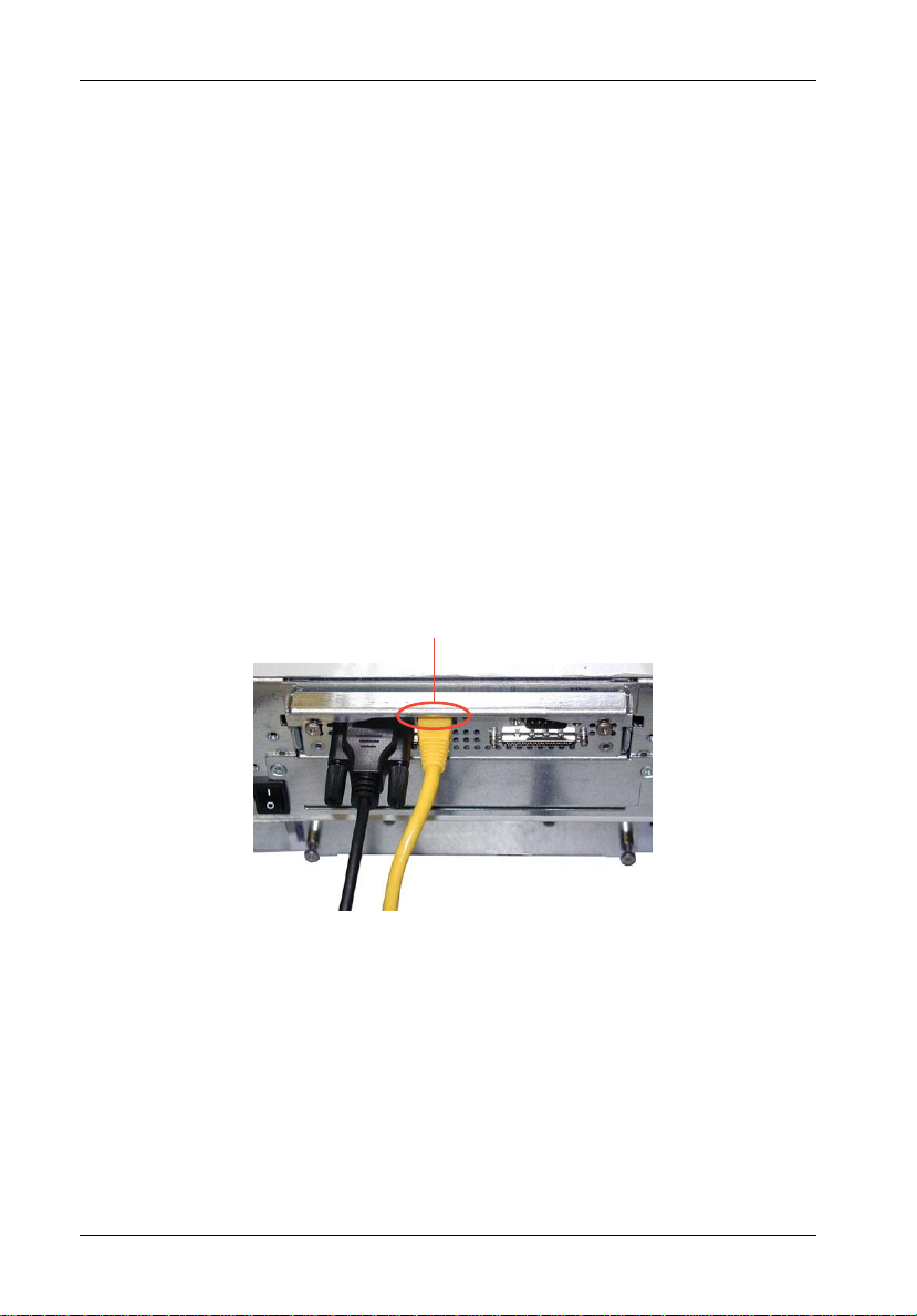
LAN Cable Connection:
NOTE: If necessary, use a small flathead screwdriver to press down on the plug re-
1. If necessary, turn OFF the InfoStation chassis.
2. Connect the InfoStation LAN Port to the LAN 10/100 hub with RJ-45 CAT5 cable (not
3. Power ON the InfoStation chassis.
lease tab when removing RJ-45 cable from the InfoStation RAID module.
Future revision will eliminate this issue.
included).
If necessary, use a small flathead screwdriver to press down on the
plug release tab when removing RJ-45 cable from the InfoStation
RAID module. Future revision will eliminate this issue.
RJ-45 CAT5 Cable
(LAN Connection)
Figure 1: InfoStation LAN Cable Installation
StorCase Technology, Inc. D89-0000-0299 Rev. A01
Page 7
InfoStation LAN Management 7
LAN MANAGEMENT
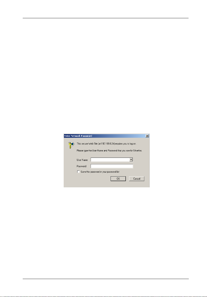
NOTE: Default InfoStation LAN IP address is 192.168.0.24. If a different IP is required,
Set-Up:
1. Verify that the InfoStation power is ON.
2. Open web browser (e.g. Microsoft IE).
3. Enter 192.168.0.24 (default IP) in the web browser's address field. You will then be
contact your network administrator for proper IP address scheme.
prompted to enter user name (default = admin) and password (default = 00000000)
as shown in Figure 2.
Figure 2: Login
D89-0000-0299 Rev. A01 StorCase Technology, Inc.
Page 8
8 InfoStation LAN Management
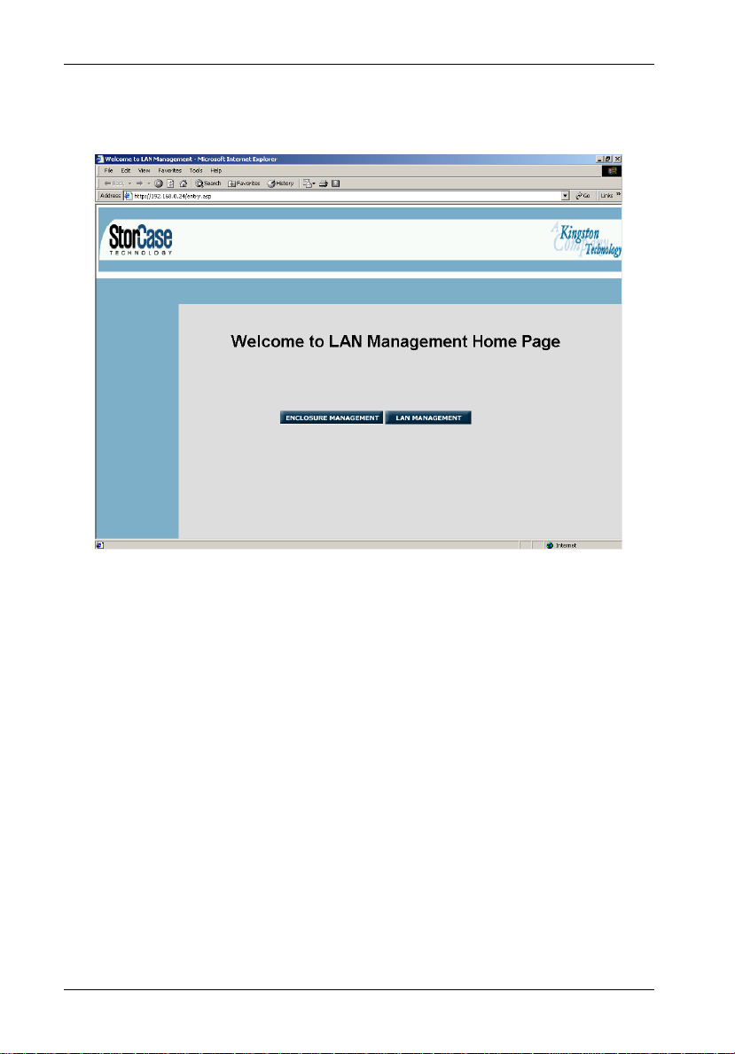
The following screen should appear (Figure 3).
Figure 3: LAN Management Start Screen
Click on LAN Management to configure LAN settings. Proceed to Figure 4.
For enclosure monitoring, click on Enclosure Management. Proceed to section "Enclosure
Management" on page xx for further information.
StorCase Technology, Inc. D89-0000-0299 Rev. A01
Page 9
InfoStation LAN Management 9
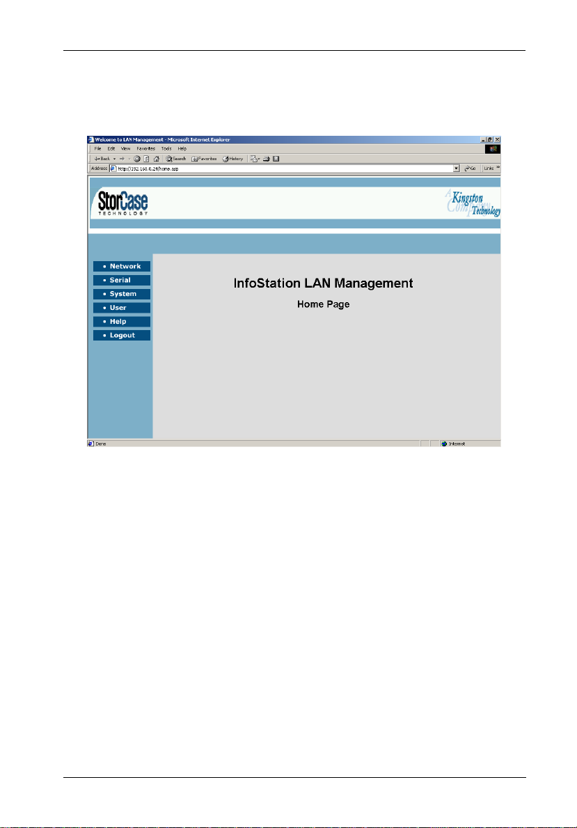
The LAN Management Home Page should appear (Figure 4).
Figure 4: LAN Management Home Screen
Proceed to section “Basic LAN Configuration" on next page.
D89-0000-0299 Rev. A01 StorCase Technology, Inc.
Page 10

10 InfoStation LAN Management
Basic LAN Configuration:
This screen allows the user to configure basic network parameters.
1. From the Home Page, click on Network.
The following screen should appear (Figure 5).
Figure 5: Basic Network Configuration Screen
2. If necessary, select the desired IP option (Dynamic, Auto, or Static) and enter the
appropriate IP, Netmask, and Gateway addresses.
NOTES: Default InfoStation LAN IP address is 192.168.0.24. If a different IP is
3. Confirm all settings and click Save.
StorCase Technology, Inc. D89-0000-0299 Rev. A01
required, contact your network administrator for proper IP address
scheme.
Static IP (default) is recommended.
Dynamic IP requires DHCP server.
Page 11

InfoStation LAN Management 11
Advanced LAN Configuration:
NOTE: Contact your network administrator for assistance with advanced LAN con-
This screen allows the user to configure advanced network parameters and email alert option.
1. From the Network screen, click on Advanced.
figuration.
The following screen should appear (Figure 6).
Figure 6: Advanced Network Configuration Screen
2. Do not change Web Server Port Number (default = 80).
3. Do not change Telnet Server (default = enabled) or Server Port number (default = 23).
4. If desired, enter an email address to which email alerts can be sent to.
5. Enter the proper DNS Primary Server and Secondary Server IP addresses in their
respective fields.
6. Confirm all settings and click Save.
D89-0000-0299 Rev. A01 StorCase Technology, Inc.
Page 12

12 InfoStation LAN Management
Basic Serial Configuration
This screen allows the user to configure basic serial port parameters.
1. From the left navbar (InfoStation LAN Management), click on Serial.
Once the top navbar appears, click on Basic.
The following screen should appear (Figure 7).
Figure 7: Basic Serial Port Configuration Screen
2. Verify that the Port option is set to com1. If necessary, select com1 from the
dropdown list.
3. Click Save.
StorCase Technology, Inc. D89-0000-0299 Rev. A01
Page 13

InfoStation LAN Management 13
Advanced Serial Configuration
This allows the user to disable the serial port (DB9). Disabling the serial port enables LAN
connection via RJ-45 port (required for LAN management).
To verify:
1. From the left navbar (InfoStation LAN Management), click on Serial.
Once the top navbar appears, click on Advanced.
The following screen should appear (Figure 8).
Figure 8: Advanced Serial Port Configuration Screen
2. Verify that the DB9 option is set to Disable. If necessary, select Disable from the
dropdown list.
3. Click Save.
You are now ready to proceed with RAID Configuration Set-Up.
D89-0000-0299 Rev. A01 StorCase Technology, Inc.
Page 14

14 InfoStation LAN Management
System Status
This screen allows the user to view system information, such as software revision and IP/
MAC addresses. No changes can be made in this screen.
1. From the left navbar (InfoStation LAN Management), click on System.
Once the top navbar appears, click on Status.
The following screen should appear (Figure 9).
Figure 9: System Status Screen
StorCase Technology, Inc. D89-0000-0299 Rev. A01
Page 15

InfoStation LAN Management 15
System Time
This screen allows the user to configure system time and date.
1. From the left navbar (InfoStation LAN Management), click on System.
Once the top navbar appears, click on Time.
The following screen should appear (Figure 10).
Figure 10: System Time Screen
2. Select either Manual (default) or Auto.
3. If Manual is selected, enter the correct date/time/location settings.
4. Confirm all settings and click Save.
D89-0000-0299 Rev. A01 StorCase Technology, Inc.
Page 16

16 InfoStation LAN Management
System View Log
This screen allows the user to refresh or clear event logs.
1. From the left navbar (InfoStation LAN Management), click on System.
Once the top navbar appears, click on View Log.
The following screen should appear (Figure 11).
Figure 11: System View Log
2. Click Refresh to refresh event log.
3. Click Clear to clear event log.
StorCase Technology, Inc. D89-0000-0299 Rev. A01
Page 17

InfoStation LAN Management 17
System Default
NOTE: This will reset the system to default configuration!
This screen allows the user to reset system to default configuration. Previous configuration will be lost.
1. From the left navbar (InfoStation LAN Management), click on System.
Once the top navbar appears, click on Default.
The following screen should appear (Figure 12).
Figure 12: System Default
2. Click Confirm to reset system to default configuration.
D89-0000-0299 Rev. A01 StorCase Technology, Inc.
Page 18

18 InfoStation LAN Management
Changing Administrator Password
NOTES: Default user name = admin
1. From the left navigation bar (navbar), click on System.
Default password = 00000000
Password can be any combination of letters and numbers, but must be eight
(8) characters long.
Once the top navbar appears, click on Password.
The following screen should appear (Figure 13).
Figure 13: Admin Password Change Screen
2. Enter the new password (must be 8 characters long) in the "New Password" field.
3. Re-enter the new password in the "Verify Password" field.
4. Click on Change Password.
The admin password is now changed.
StorCase Technology, Inc. D89-0000-0299 Rev. A01
Page 19

InfoStation LAN Management 19
System Upgrade
NOTE: This option is reserved for future use.
TBA.
Figure 14: System Upgrade Screen
D89-0000-0299 Rev. A01 StorCase Technology, Inc.
Page 20

20 InfoStation LAN Management
Downloading Configuration
NOTE:
1. Click Download Now.
Save the configuration file to a known directory on your host computer's hard drive.
Restoring Configuration
NOTE:
1. Browse to the known directory and select the configuration file.
2. Click Restore.
StorCase Technology, Inc. D89-0000-0299 Rev. A01
Page 21

InfoStation LAN Management 21
Adding User Access Rights
NOTE: Password can be any combination of letters and numbers, but must be eight
1. From the left navbar, click on User .
(8) characters long.
The following screen should appear (Figure 15).
Figure 15: Add User Screen
2. Enter the user name in the "Name" field.
3. Enter the user password in the "Password" field.
3. Re-enter the new password in the "Verify Password" field.
4. Click on Save.
The user name should now appear in the "List of Users" section.
5. If necessary, repeat Steps 2-4 to add more users.
6. To delete user access rights, simply select the name from the "List of Users" section
and click Delete.
D89-0000-0299 Rev. A01 StorCase Technology, Inc.
Page 22

22 InfoStation LAN Management
Help
1. From the left navbar, click on Help.
The following screen should appear (Figure 16).
Figure 16: Help Screen
2. Click on the link corresponding to the desired topic to view information.
StorCase Technology, Inc. D89-0000-0299 Rev. A01
Page 23

InfoStation LAN Management 23
Logout
1. From the left navbar, click on Logout.
The following screen should appear (Figure 17).
Figure 17: Logout Screen
D89-0000-0299 Rev. A01 StorCase Technology, Inc.
Page 24

24 InfoStation LAN Management
ENCLOSURE MANAGEMENT
NOTES: Some Task Menu options are not available for all InfoStation models (unavailable
1. From the LAN Management Start page (Figure 3), click on Enclosure Management.
options will be grayed-out).
Refer to the InfoMon User's Guide for further information.
The InfoMon main screen should appear (Figure 18).
You are now ready to view chassis environmental information with InfoMon.
Figure 18: InfoMon Main Screen
(Actual screen may vary)
Refer to the InfoMon User's Guide for further information.
StorCase Technology, Inc. D89-0000-0299 Rev. A01
Page 25

InfoStation LAN Management 25
RAID MANAGEMENT
Before proceeding with set-up, verify that the InfoStation LAN Management Serial Port (DB9)
option is Disabled. Refer to section "Advanced Serial Configuration" (page 13) for further
information.
Set-Up:
1. Insert the CD (provided) into your computer's CD-ROM drive.
2. Open the CD-ROM directory through "My Computer" or Windows Explorer.
3. Save the SCRAIDMGMT.exe file on to your computer's desktop.
4. Once the file has been saved, double-click the icon to open SCRAIDMGMT.
The following box should appear (Figure 19).
Figure 19: SCRAIDMGMT Box
5. The default IP (192.168.0.24) will display in the "Host" field.
If default IP is used, click OK to proceed.
If a different IP is used, enter the new IP in the "Host" field and click OK to proceed.
The following screen should appear (Figure 20A).
D89-0000-0299 Rev. A01 StorCase Technology, Inc.
Page 26

26 InfoStation LAN Management
Figure 20A: Login Screen
6. Login as root (or by user name and password, if already set) and press <ENTER>.
The following screen should appear (Figure 20B).
Figure 20B: Command Screen
StorCase Technology, Inc. D89-0000-0299 Rev. A01
Page 27

InfoStation LAN Management 27
7. Run minicom (type minicom and press <ENTER>).
The following screen should appear (Figure 20C).
Figure 20C: Minicom Screen
8. Press <CTRL-D> to open the RAID Configuration menu (Figure 20D).
Refer to the appropriate InfoStation User's Guide for further information regarding
RAID configuration.
Figure 20D: RAID Configuration Menu Screen
D89-0000-0299 Rev. A01 StorCase Technology, Inc.
Page 28

28 InfoStation LAN Management
To exit:
9. Press <CTRL-A Z> to open the Help screen (Figure 20E).
10. Press <x> to exit.
Figure 20E: Help Screen
StorCase Technology, Inc. D89-0000-0299 Rev. A01
 Loading...