

Page 1

StorCase® Technology
InfoSt ation
14-Bay SCSI Ultra320
External Expansion Chassis
User's Guide
®
Page 2

StorCase® Technology
i
InfoSt ation
®
14-Bay SCSI Ultra320
External Expansion Chassis
User's Guide
Part No. D89-0000-0238 A00 June 2003
StorCase Technology, Inc.
17600 Newhope Street
Phone (714) 438-1850 Fax (714) 438-1847
InfoStation 14-Bay U320 User's Guide - Rev. A00 StorCase Technology, Inc.
Fountain Valley, CA 92708-9885
Page 3

ii
LIMITED WARRANTY
STORCASE TECHNOLOGY, Incorporated (StorCase) warrants that its products will be free
from defects in material and workmanship, subject to the conditions and limitations set forth
below. StorCase will, at its option, either repair or replace any part of its product that proves
defective by reason of improper workmanship or materials. Repair parts or replacement
products will be provided by StorCase on an exchange basis, and will be either new or
reconditioned to be functionally equivalent to new.
This warranty does not cover any product damage that results from accident, abuse, misuse,
natural or personal disaster, external power surge or failure, or any unauthorized disassembly, repair or modification. StorCase will not be responsible for any software, firmware or other
customer data stored within, or interfacing with a StorCase product.
Duration of Warranty
Seven-Year Warranty: The following StorCase products are covered by this warranty for
a period of seven (7) years from the original date of purchase from StorCase or its authorized
reseller: all Data Express® removable device enclosures and all StorCase interface cables and
accessories specifically intended for use with these products. Data Silo®, Data Stacker® and
InfoStation® products are covered by this warranty for a period of seven (7) years, excepting
the RAID controller, power supply, fan and blower components, which are covered by the
three-year warranty described below.
Three-Year Warranty: The following StorCase products are covered by this warranty for
a period of three (3) years from the original date of purchase from StorCase or its authorized
reseller: all Rhino®JR external expansion chassis, all RhinoJR removable drive enclosures,
and all RAID controller modules. In addition, the following components of the Data Express,
Data Silo, Data Stacker, InfoStation products are subject to warranty for a period of three (3)
years: all power supplies, fans and blowers.
Warranty Claim Requirements
To obtain warranty service, the defective product must be returned to your local authorized
StorCase dealer or distributor, or, with prior StorCase approval, to the StorCase factory
service center.
For defective products returned directly to StorCase, a Return Material Authorization (RMA)
number must be obtained by calling StorCase Customer Service at (714) 445-3455. The RMA
number must be prominently displayed on the outside of the return package. Shipments must
be freight-prepaid and insured, and must include the product serial number, a detailed
description of the problem experienced, and proof of the original retail purchase date. Products
must be properly packaged to prevent damage in transit. Damage resulting from improper
packaging will not be covered by this warranty. The StorCase factory service center is located
at 17650 Newhope Street, Receiving Dock, Gate #4, Fountain Valley, CA 92780, U.S.A.
StorCase Technology, Inc. InfoStation 14-Bay U320 User's Guide - Rev. A00
Page 4

Free Technical Support
StorCase provides free technical support. If you experience any difficulty during the
installation or subsequent use of a StorCase product, please contact StorCases Technical
Support Department prior to servicing your system. This warranty covers only repair or
replacement of defective StorCase products, as described above. StorCase is not liable for,
and does not cover under warranty, any costs associated with servicing and/or installation
of StorCase products.
StorCase Technical Support can be reached in the U.S. at (714) 438-1858 or toll-free at (888)
435-5460 (U.S. and Canada only). StorCase European Technical Support can be reached in
the U.K. at +44 (0) 1932 738900.
Disclaimers
The foregoing is the complete warranty for the products identified above and
supersedes all other warranties and representations, whether oral or written.
StorCase expressly disclaims all warranties for the identified products, which are
not stated herein, including, to the extent permitted by applicable law, any implied
warranty of merchantability or fitness for a particular purpose. In no event will
StorCase be liable to the purchaser, or to any user of a StorCase product, for any
damages, expenses, lost revenues, lost savings, lost profits, or any other
incidental or consequential damages arising from the purchase, use or inability
to use a StorCase product, even if StorCase has been advised of the possibility
of such damages.
iii
Copyright © 2003 StorCase Technology. All rights reserved. All registered
trademarks are the property of StorCase Technology. All other logos and trademarks
are properties of their respective companies.
InfoStation 14-Bay U320 User's Guide - Rev. A00 StorCase Technology, Inc.
Page 5
iv
Declaration of Conformity
Company Name:
Corporate Office Address:
Manufacturing Address:
Product Name:
Model Number:
Conforms to the following standards:
EMC Directives:
(89/336/EEC)
Safety Standards:
CSA (NRTL/C)
TUV:
EMI Standards:
StorCase Technology, Inc.
17600 Newhope Street
Fountain Valley, CA 92708
17600 Newhope Street
Fountain Valley, CA 92708
InfoStation 14-Bay Ultra320
S10A168, S10A169, S10A170
EN 50081-1: 1992 Generic Emission
- EN 55022/CISPR22 Class A
EN 55024: 1998 ITE Immunity
- EN 61000-4-2 - EN 61000-4-6
- EN 61000-4-3 - EN 61000-4-8
- EN 61000-4-4 - EN 61000-4-11
- EN 61000-4-5
CAN/CSA-C22.2 No. 60950
UL 60950, Third Edition
EN 60950: 2000
FCC Part 15, Class A
EMC Standards:
Year of Manufacture:
Signature:___________________
Full Name: Dieter Paul
Position: President
StorCase Technology, Inc. InfoStation 14-Bay U320 User's Guide - Rev. A00
AS/NSZ 3548 Information Technology Equipment
2003
Page 6

Federal Communications Commission (FCC) Statement
RADIO FREQUENCY INTERFERENCE STATEMENT
You are cautioned that changes or modifications not expressly approved by the party
responsible for compliance could void your authority to operate that equipment.
This device complies with part 15 of the FCC rules. Operation is subject to the following two
conditions: (1) This device may not cause harmful interference, and (2) This device must
accept any interference received, including interference that may cause undesired operation.
Important Safety Instructions
1. Read all these instructions.
2. Save these instructions for later use.
3. Follow all warnings and instructions marked on the product.
4. Do not use this product near water.
5. This product should be operated from the type of power source indicated on the
marking label. If you are not sure of the type of power available, consult your dealer
or local power company.
6. Do not attempt to service this product yourself, as opening or removing covers may
expose you to dangerous voltage points or other risk. Refer all servicing to service
personnel.
v
Wichtige Sicherheitshinweise
1. Diese Hinweise sollten vollständig durchgelesen werden.
2. Diese Hinweise für einen späteren Gebrauch aufbewahren.
3. Allen auf dem Gerät angebrachten Warnungen und Hinweisen folgen.
4. Das Gerät nicht in der Nähe von Wasser verwenden.
5. Das Gerät nur mit dem Aufkleber bezeichneten Netzspannung betreiben. Bei Fragen
über die Art der Netzspannung sollte der Händler oder das
Energieversorgungsunternehmen zu rate gezogen werden.
6. Nicht versuchen das Produkt selbst zu reparieren. In allen Produkten existieren
gefährliche elektrische Spannugen. Nicht das Gehäuse öffnen.
7. Wartungsarbeiten nur von qualifiziertern Kundendienstpersonal ausführen laßen.
InfoStation 14-Bay U320 User's Guide - Rev. A00 StorCase Technology, Inc.
Page 7

vi
Table of Contents
INTRODUCTION ..................................................................................................................... 1
Packaging Information .................................................................................................. 1
Serial Number ................................................................................................................ 1
General Description ...................................................................................................... 2
Front Panel ............................................................................................................ 4
Rear Panel ............................................................................................................. 6
INFOSTATION USER INTERFACE ......................................................................................... 8
Display and Control Panel ............................................................................................ 8
Default Display Mode.......................................................................................... 10
InfoStation Menu System ................................................................................... 12
InfoStation Environmental Information and Set-Up ................................................... 13
System Error Status ........................................................................................... 14
Drive Bay SCSI ID Configuration ........................................................................ 15
Spin-Up Option Set-Up ....................................................................................... 17
SAF-TE Processor Board SCSI ID Set-Up ........................................................ 19
SAF-TE Processor Board Multiple LUN Set-Up ................................................ 20
Enabling/Disabling the Buzzer ........................................................................... 21
Enclosure ID Set-Up ........................................................................................... 22
Changing the Blower Speed.............................................................................. 23
Serial Port Set-Up ............................................................................................... 24
Fibre Channel Speed Set-Up ............................................................................. 26
Banner Set-Up .................................................................................................... 27
Firmware Revision ............................................................................................. 28
Drive Bay Interface Panel .......................................................................................... 29
Insert/Remove Push Button ............................................................................... 30
Inserting a Drice Carrier (with Drive Installed) ................................................. 30
Removing a Drive Carrier (with Drive Installed) ............................................... 30
SCSI CHANNEL CONFIGURATIONS ................................................................................... 31
Termination of the SCSI Bus at the VHDCI Connectors ........................................... 31
Ultra320 I/O Repeater Module ............................................................................ 31
Single-Channel InfoStation ......................................................................................... 32
Dual-Channel InfoStation............................................................................................ 33
4-Channel InfoStation ................................................................................................. 34
Typical SCSI Channel Configurations........................................................................ 35
StorCase Technology, Inc. InfoStation 14-Bay U320 User's Guide - Rev. A00
Page 8

Table of Contents (cont'd)
APPENDICES ........................................................................................................................ 39
Appendix A - Specifications/Dimensions .................................................................. 40
Appendix B - Optional Accessories......................................................................... 44
Ultra320 I/O Repeater Kit ................................................................................... 44
SAF-TE Processor Board .................................................................................. 45
RAID Controller Modules .................................................................................... 46
SNMP Module ...................................................................................................... 49
Slide Rail Kit......................................................................................................... 50
Optional Power Supply Module .......................................................................... 51
Optional Blower Module ..................................................................................... 52
Drive Carrier ........................................................................................................ 52
Carrying Case ..................................................................................................... 53
InfoStation Monitoring Utility (InfoMon) .............................................................. 54
Reader's Comments............................................................................................................ 55
List of Figures
Figure 1: InfoStation 14-Bay.......................................................................................... 2
Figure 2: InfoStation Front Panel ................................................................................... 5
Figure 3: InfoStation Rear Panel .................................................................................... 7
Figure 4: Display and Control Panel .............................................................................. 8
Figure 5: InfoStation Drive Carrier Interface .............................................................. 29
Figure 6: InfoStation VHDCI Connectors (Ultra320 I/O Repeater Module) ................ 31
Figure 7: Single-Channel InfoStation I/O Module Location ......................................... 32
Figure 8: Dual-Channel InfoStation I/O Module Location............................................ 33
Figure 9: 4-Channel InfoStation I/O Module Location ................................................. 34
Figure 10: Typical Single SCSI Host Connection to InfoStation ................................... 35
Figure 11: Typical Dual SCSI Host Connection to InfoStation ...................................... 36
Figure 12: Typical Quad SCSI Host Connection to InfoStation .................................... 37
vii
Figure A-1: InfoStation 14-Bay Physical Dimensions .................................................... 43
Figure B-1: Ultra320 I/O Repeater Kit ............................................................................. 44
Figure B-2: SAF-TE Processor Board ............................................................................ 45
Figure B-3: SCSI-to-SCSI Dual RAID Controller Module Unit ......................................... 46
Figure B-4: FC-to-SCSI Dual RAID Controller Module Unit ............................................. 47
Figure B-5: Single RAID Controller Module Upgrade ...................................................... 48
Figure B-6: SNMP Module ................................................................................................ 49
Figure B-7: Rack Mount Slide Rail Kit .............................................................................. 50
Figure B-8: Power Supply Module .................................................................................. 51
Figure B-9: Blower Module .............................................................................................. 52
Figure B-10: Drive Carrier ................................................................................................. 52
Figure B-11: Carrying Case ............................................................................................... 53
InfoStation 14-Bay U320 User's Guide - Rev. A00 StorCase Technology, Inc.
Page 9

viii
List of Tables
Table 1: Display and Control Panel Components .............................................................. 9
Table 2: InfoStation Menu Navigation Switches ............................................................. 12
Table 3: Default Bay SCSI ID Assignments ..................................................................... 15
Table 4: Motor Spin Functions ......................................................................................... 18
Table 5: Drive Carrier Interface Components ................................................................. 29
NOTICE: This User's Guide is subject to periodic updates without notice. While reasonable
StorCase Technology, Inc. InfoStation 14-Bay U320 User's Guide - Rev. A00
efforts have been made to ensure accuracy of this document, Storcase Technology, Inc. assumes no liability resulting from errors or omissions in this publication,
or from the use of the information contained herein.
Please check the StorCase web site at http://www.storcase.com or contact your
StorCase representative for the latest revision of this document.
Page 10

Introduction 1
INTRODUCTION
CAUTION: The InfoStation contains NO USER SERVICEABLE parts inside the unit.
NOTES: The installation, configuration, and use of the StorCase InfoStation chas-
Refer ALL servicing to qualified service personnel!
VHDCI connectors are easily damaged by improper handling. Visually
inspect each connector for bent contacts and carefully align prior to
insertion.
sis requires a certain level of expertise and experience on the part of the
user/integrator. Since there are many configuration options and variables
(ie. host platforms, applications, etc), only general/typical configuration
guidelines will be discussed in this User's Guide.
For installation information, refer to the InfoStation Installation Guide.
PackagingInformation
The StorCase Technology InfoStation external expansion chassis is shipped in a container
designed to provide protection and prevent damage during shipment, as confirmed by the
International Safe Transit Association (ISTA Procedure 1A). The InfoStation was carefully
inspected before and during the packing procedure at the factory. Evidence of any damage
to the InfoStation should be reported to the shipper immediately.
If the wrong InfoStation model has been received, please call your reseller or StorCase at
(800) 435-0642 to arrange for a Return Material Authorization (RMA). StorCase cannot accept returns which do not display an RMA number on the outside of the package. Return the
unit with all the original packing materials.
Before removing any component from its packaging, discharge any static electricity by
touching a properly grounded metal object.
Serial Number
The InfoStation is labeled with a serial number. This number must be reported to the StorCase
Customer Service Representative in order to receive a Return Material Authorization (RMA)
for warranty claims. Locate the serial number label and record the number in the space
provided below.
InfoStation Serial Number:
InfoStation 14-Bay U320 User's Guide - Rev. A00 StorCase Technology, Inc.
Page 11
2 Introduction
GeneralDescription
NOTE: For SCSI Ultra320 operation, the InfoStation requires Ultra320 drives,
Ultra320 HBA, Ultra320-compliant cabling (internal and external), and
Ultra320 repeater modules installed.
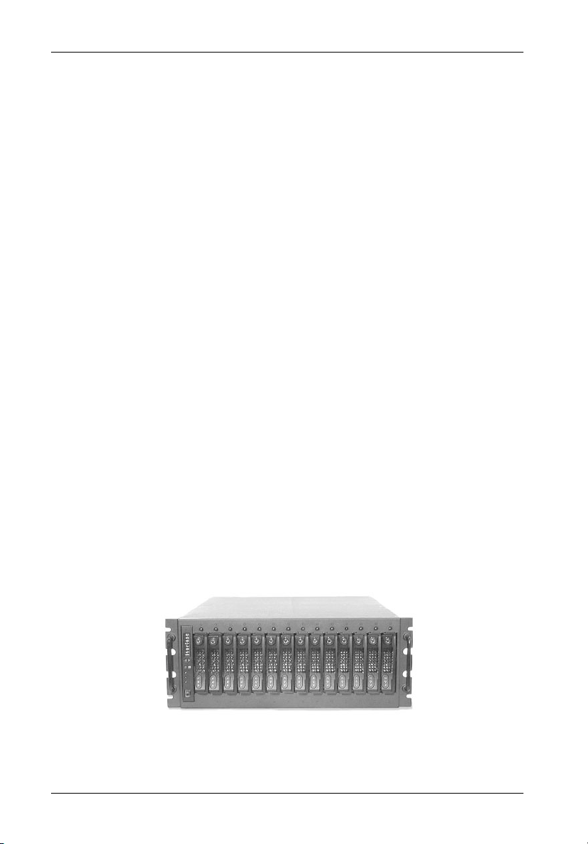
The StorCase® Technology InfoStation® intelligent rack-mount expansion chassis is
designed to support the latest high-density, high-speed SCSI disk drive technologies for use
in network server, fault-tolerant and/or mission-critical applications. The InfoStation is
designed to support 3.5" form factor, low profile (1" high) SCSI Ultra320 devices.
The InfoStation's backplane design can accommodate up to fourteen (14) single-connect SCA
SCSI devices (Figure 1). Each chassis is constructed of rugged steel, lightweight aluminum
and plastic, and is equipped with Two (2) 650 watt redundant, hot-swappable power supply
modules, Two (2) redundant, hot swappable blower modules (depending on the model) and
a User Interface module designed to provide continual chassis data feedback and control of
drive configurations.
The InfoStation SCSI backplane comes standard with either one (1), two (2), or four (4) Ultra320
repeater modules (for Ultra320 operation and daisy-chaining applications). InfoStation can
easily be upgraded with additional I/O repeater modules to support up to four channels (refer
to Appendix B for further information).
The InfoStation also incorporates "Soft Start" circuitry which eliminates in-rush current to each
of the installed drives during spin-up, as well as avoid power arcing during drive insertion.
Another unique feature of the InfoStation is the InfoMon® monitoring utility program. InfoMon
is a console utility that provides the InfoStation with web-based monitoring capability via a serial
connection. InfoMon also provides the User the ability to easily configure both device and
chassis settings with a few clicks of the mouse! Refer to Appendix B for further information
on InfoMon.
IFS14_1
Figure 1: InfoStation 14-Bay
StorCase Technology, Inc. InfoStation 14-Bay U320 User's Guide - Rev. A00
Page 12

Introduction 3
The latest versions of the InfoMon utility program and User's Guide can be downloaded (free
of charge) from the StorCase web site (http://www.storcase.com). Contact StorCase for
further information. Refer to Appendix B for further information on optional InfoStation
accessories.
A SAF-TE Processor Board is also available as an InfoStation upgrade option. Refer to
Appendix B for further information on optional InfoStation accessories.
Using a modular approach supported by redundant features and hot swapping capabilities,
the InfoStation will provide continued data availability and allow for ease of maintenance and
minimal system down time.
The modular and scalable design of the InfoStation chassis also allows a variety of product
upgrades to be offered, such as Dual SCSI-to-SCSI and FC-to-SCSI RAID Controller modules.
Upgrade modules (such as SNMP) are anticipated InfoStation options.
This User's Guide describes the steps required for installing drive(s) into the InfoStation
external expansion chassis. This guide is intended to supplement documentation provided with
the host computer system, the operating system, and the drive(s) to be installed within the
InfoStation.
Features:
4U Rack Mount Chassis
Fourteen (14) removable low-profile drive carriers
SCSI Ultra320 drive support
Scalable backplane design
Corrosion-resistant steel construction
Two (2) hot-swappable high-pressure/variable-speed blower modules
Two (2) 650W hot-swappable power supply modules
Eight-Character scrolling display and control panel
Audible alarm
Status indicators at each bay
1, 2, or 4-Channel Configurable
RAID ready (Optional SCSI-to-SCSI and FC-to-SCSI RAID Controller Modules
"Soft Start" circuitry
Web-based monitoring utility
7-year limited warranty* and free 24/7 technical support
available)
* 3 year limited warranty on Power & Cooling modules
InfoStation 14-Bay U320 User's Guide - Rev. A00 StorCase Technology, Inc.
Page 13

4 Introduction
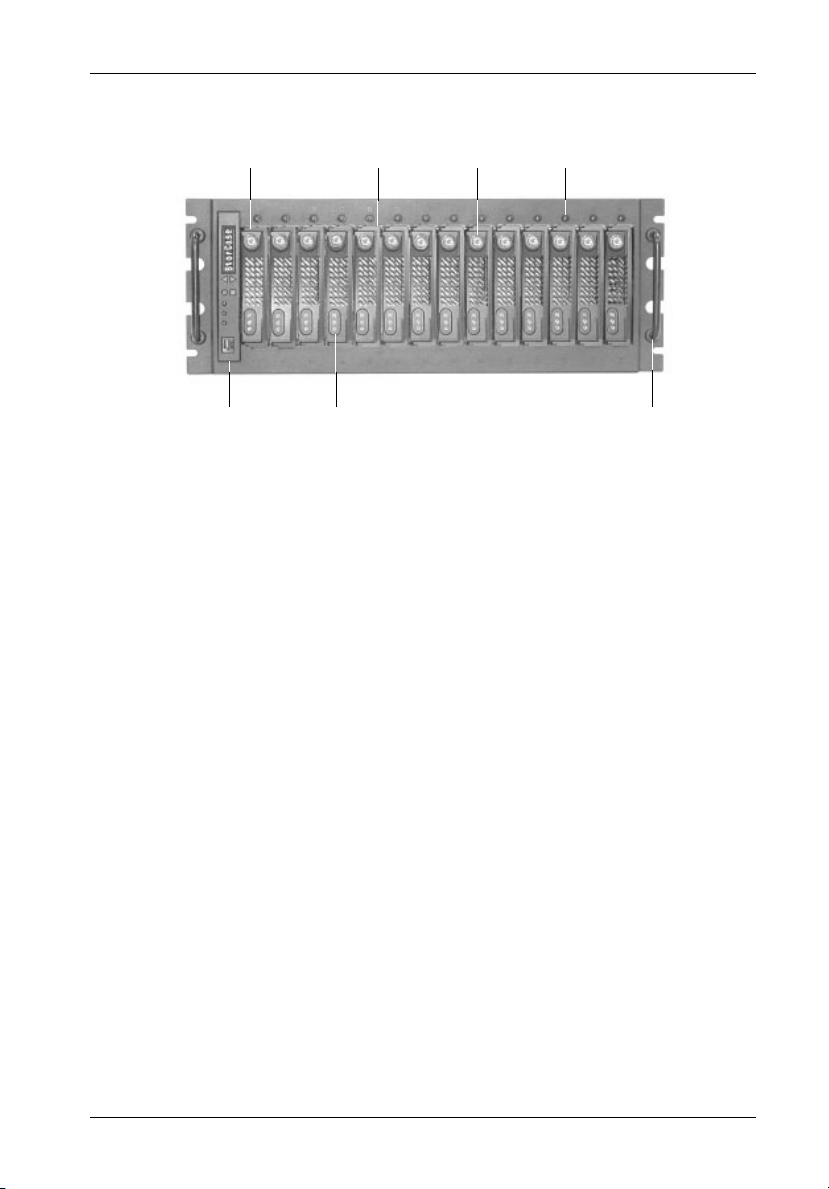
FrontPanel
(Figure 2)
User Interface Module (UIM) - Provides control of drive set-up options while the
8-character LED panel displays system statuses, alarms, and warnings. Refer to
section "InfoStation User Interface" for further information.
SCA Drive Carrier(s) - Accommodate up to fourteen (14) 3.5" low-profile single-
connect SCSI devices. Backplane design with direct-connect SCA connectors
eliminates cable connections to SCSI drives, increases data integrity, and supports
drive hot swappability.
Drive Carrier LED(s) - Provides the following information:
Drive Ready - Indicates that the drive is properly installed and ready for
access.
Drive Activity - Indicates that the drive is being accessed.
Drive Fault - Indicates a drive failure.
Key Lock(s) - Assure proper seating of the drive carrier within the chassis and
prevent unauthorized removal or installation of the carrier.
NOTE: The key lock is only to prevent unauthorized removal or installation of the
Insert/Remove Push Button(s) - Allow the drive carrier(s) to be removed and
installed at anytime (Refer to the InfoStation Installation Guide for further information).
Chassis Handle(s) - Provide a sturdy grip for the installation and removal of the
rack-mount chassis.
StorCase Technology, Inc. InfoStation 14-Bay U320 User's Guide - Rev. A00
drive carrier. Locking the key lock is not requried for drive carrier operation.
Page 14
Introduction 5
SCA Drive
Carrier
User Interface
Module
Drive Carrier
Drive Carrier
LEDs
Handle
Top
Key
Lock
Figure 2: InfoStation Front Panel
Insert/Remove
Push Button
IFS14_2
Chassis
Handle
InfoStation 14-Bay U320 User's Guide - Rev. A00 StorCase Technology, Inc.
Page 15

6 Introduction
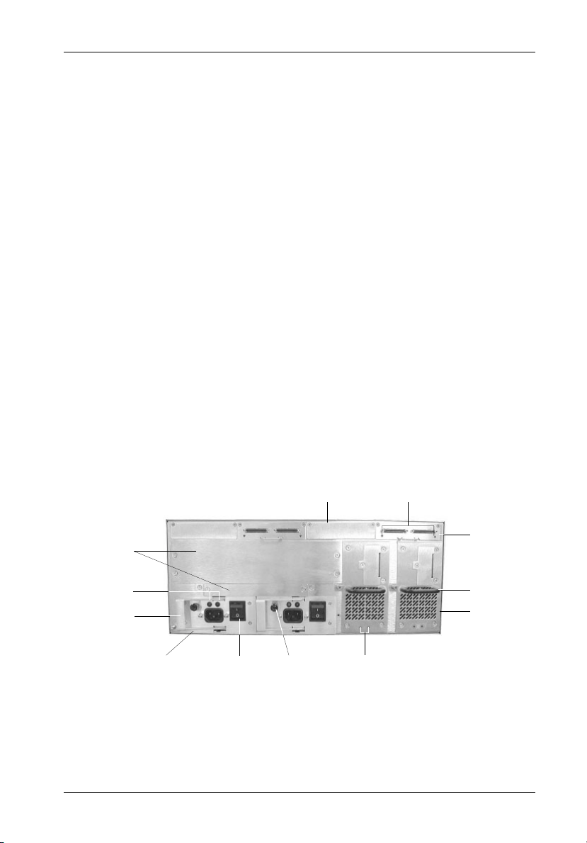
RearPanel
(Figure 3)
I/O Repeater Module(s) - InfoStation comes equipped with either one, two, or four
Ultra320 repeater modules. Additional I/O repeater modules are available, for up to
four (4) channels. Refer to Appendix B for further information.
NOTE: For SCSI Ultra320 operation, the InfoStation requires Ultra320 drives,
I/O Repeater Module LED(s) -
Refer to the UIM or InfoMon for detailed information on I/O repeater module status.
I/O Blank Plate(s) - May be removed when installing additional I/O repeater modules.
NOTE: Blank plate (provided) must be installed if any module slot is left
Blower Module(s) - Depending on the model, either single or dual redundant, hot
swappable modules each with two (2) high-pressure blowers inside, provide ample
cooling for high speed drives (79 CFM each module). Each module features blower
fault detection, total usage hours, and self-adjusting blowers for optimal cooling
performance.
Ultra320 HBA, Ultra320-compliant cabling (internal and external), and
Ultra320 repeater modules installed.
Error LED (Amber) - Flashing indicates a detection in either:
1. Over temperature
2. Low termination voltage
3. Invalid differential voltage
Activity LED (Green) - ON indicates activity is present.
OFF indicates there is no activity present.
empty. Installation of the blank plate is necessary for proper
cooling inside chassis.
Blower Module LED(s) -
Green LED - Steady glow indicates normal blower operation.
Red LED - Flashing indicates at least one blower failure.
Module Handle(s) - Provide a sturdy grip for the installation and removal of the
InfoStation modules.
WARNING: DO NOT USE MODULE HANDLES TO LIFT CHASSIS! These
StorCase Technology, Inc. InfoStation 14-Bay U320 User's Guide - Rev. A00
handles are specifically designed for the installation and removal of modules only!
Page 16
Introduction 7
Power Supply Module(s) - Depending on the model, either one (1) or two (2) 650W
redundant, hot swappable power supply modules. Each module features overvoltage and overcurrent protection, total usage hours, and power supply fault detection.
Power Supply Module LED(s) -
Green LED - Steady glow indicates normal power supply operation.
No glow indicates no A/C power or abnormal DC voltage range.
Red LED - Flashing indicates temperature or over/undervoltage condi-
tions.
Power Supply Handle(s) with Locking Thumbscrew(s) - Lock the power
supply module into the InfoStation chassis and allow for easy installation and removal
of the power supply module(s).
Power Switch(es) - Rocker switch(es) control power to the power supply
module(s).
A/C Power In - Accepts U.S. and other available international standard power
cables.
Module Options - Allow the installation of StorCase upgrade products such as
optional Dual SCSI-to-SCSI or FC-to-SCSI RAID controller modules. Upgrade modules
(such as SNMP), are also anticipated InfoStation options.
I/O Repeater
Module LEDs
I/O Repeater
Module
Module
Options
I/O Blank
Plate
Power Supply
Module LEDs
Power Supply
Handle
Power Supply
Module
Power
Switch
Locking
Thumbscrew
Blower
Module
LEDs
Module
Handle
Blower
Module
Figure 3: InfoStation Rear Panel
(Dual-Channel Version shown)
InfoStation 14-Bay U320 User's Guide - Rev. A00 StorCase Technology, Inc.
Page 17
8 InfoStation User Interface
INFOSTATION USER INTERFACE
CAUTION: The User Interface Module contains NO USER SERVICEABLE PARTS in-
side the unit. Warranty is VOID if module is opened. Refer all servicing
to qualified service personnel!
The StorCase InfoStation is an intelligent external expansion chassis. Each InfoStation is
equipped with a comprehensive User Interface (UI) which provides chassis status based on
several internal environmental sensors. This section describes the InfoStation UI features and
functions.
The UI has two (2) main functions:
1. To display the enclosure's environmental status and indicate alarm conditions
2. To interact with the User to select drive bay SCSI IDs and the Enclosure ID
The UI is comprised of the following two components:
1. Display and Control Panel
2. Drive Carrier Indicators (LEDs) and Insert/Remove Push Buttons (14 total)
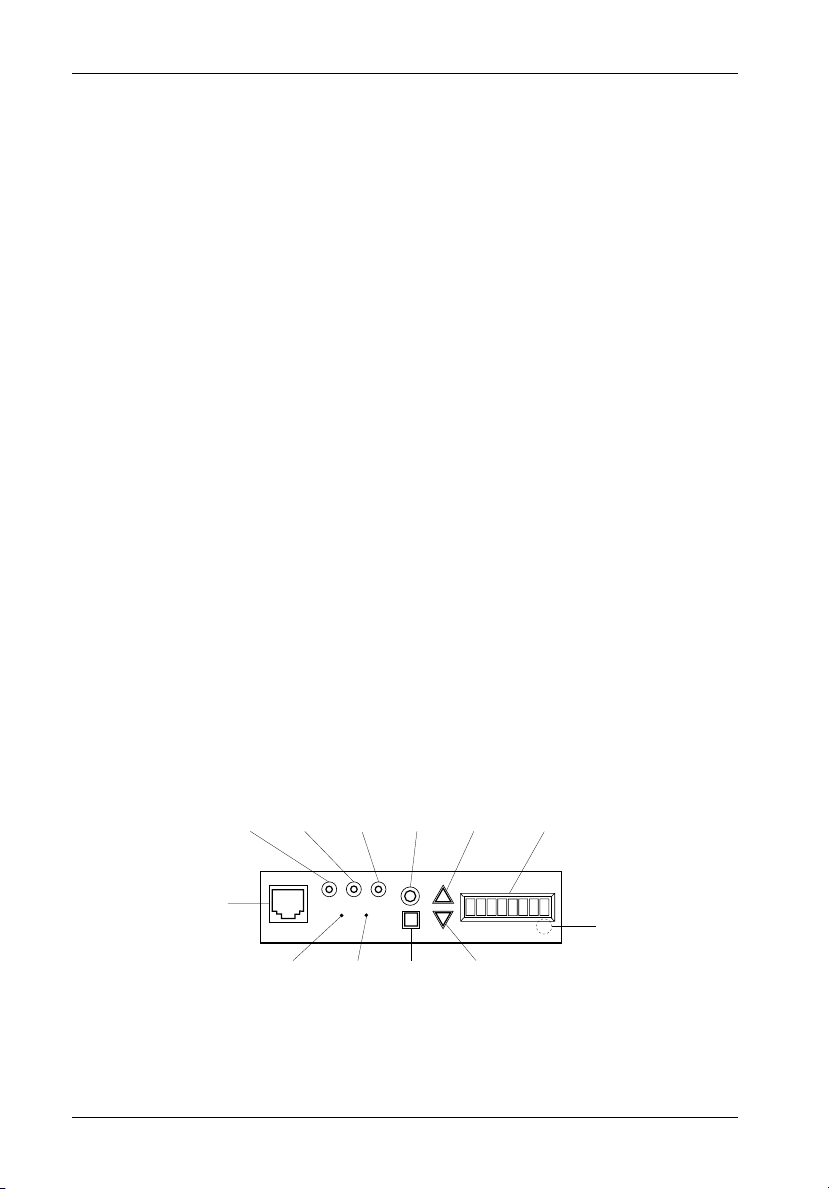
Display and Control Panel
(Figure 4)
The InfoStation Display and Control Panel provides an 8-character scrolling display, system
status LEDs and control buttons (which allow the User to select system drive bay SCSI IDs,
Enclosure ID, etc.), and also to view up-to-date chassis environmental conditions.
Mute
LED
Drive
Shutdown
Override
LED
Shutdown
Override
Switch
Enter
Button
Cancel
Button
Scroll
Up
Button
Scroll
Down
Button
LED
Display
IFS_6
Hidden
Buzzer
RJ45
Connector
(Serial Port)
System
Error
LED
Buzzer
Master
Reset
Switch
Figure 4: Display and Control Panel
StorCase Technology, Inc. InfoStation 14-Bay U320 User's Guide - Rev. A00
Page 18
InfoStation User Interface 9
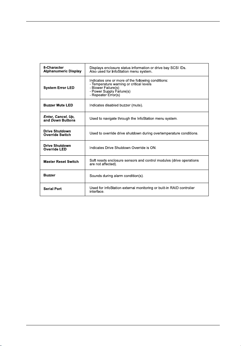
Table 1: Display and Control Panel Components
NOTE: Alarm conditions cannot be reset! An alarm condition will automatically
InfoStation 14-Bay U320 User's Guide - Rev. A00 StorCase Technology, Inc.
reset when the status of the failed component returns to normal.
Page 19

10 InfoStation User Interface
The UI Module (together with the drive bay, blower, power supply, and I/O modules) provides
the following enclosure monitoring and control capabilities:
1. Average internal temperature and the ambient external temperature of the InfoStation
2. InfoStation system 5V and 12V readings
3. SCSI mode for each channel - LVD or SE
4. Type of RAID Controller Module installed
5. Buzzer enable/disable
6. Drive bay SCSI ID set-up
7. Drive bay spin-up options set-up
8. Start-up banner set-up
9. Enclosure ID set-up
10. Serial port set-up
11. Variable blower speed levels
12. Fibre channel speed set-up
13. SAF-TE SCSI ID set-up
14. SAF-TE Board multiple LUN set-up
chassis
Default Display Mode
After the InfoStation's start up sequence, the front panel display will show the temperature
inside the enclosure. Under normal operation, the display shows the average temperature
of the enclosure:
T e m p : x x C
This display mode shows the enclosure's average temperature reading, with xx representing
the degrees in Celsius. The colon (:) will blink, indicating that the IFS II monitoring circuitry is
working.
NOTE: This display will be referred to as the Factory-Default Display.
StorCase Technology, Inc. InfoStation 14-Bay U320 User's Guide - Rev. A00
Page 20

InfoStation User Interface 11
At the Factory-Default Display, the user can view the User-Selectable Default Displays
(shown below) by simply using the UP and DOWN keys (refer to section "InfoStation Menu
System" for further information).
B A N N E R
This display shows either the factory-default banner (StorCase), or a user-defined one. A
user-defined banner can be up to 8-characters long. The banner can be set with either the
UI Module (refer to section "Banner Set-Up" for further information) or via the InfoMon software
(refer to the InfoMon User's Guide for further information).
h h : m m z
This display shows the time maintained by the InfoStation. hh represents the hour and mm
is the minute. z represents A or P in the 12-hour time format (or blank if in the 24-hour time
format). The colon (:) will blink, indicating that the IFS II monitoring circuitry is working.
NOTE: The 24-hour time format is factory-default. To change into the 12-hour time
(AM/PM) format, the InfoMon software must be used (refer to the InfoMon
User's Guide for further information).
E n c I D : x x
This display shows the enclosure ID, with xx representing the ID number. The colon (:) will
blink, indicating that the IFS II monitoring circuitry is working.
InfoStation 14-Bay U320 User's Guide - Rev. A00 StorCase Technology, Inc.
Page 21

12 InfoStation User Interface
InfoStation Menu System
The menu system navigation is done using the Enter, Cancel, Up, and Down switches.
The following table describes the specific function of each navigation button.
Table 2: InfoStation Menu Navigation Switches
Switch
Enter
Description
This button is used to select an item at any level. If the Enter
button is pushed at the last menu item, a detailed description
of that particular menu item will be scrolled across the display.
Up
Down
These buttons are used to scroll through the available options
for any particular menu list.
This button is used to terminate the menu system and return
Cancel
to the Default Display Mode. The menu system will automatically cancel after 15 seconds of User inactivity.
The first menu level is entered when the Enter button is pushed at the Default Display. Only
one menu item of a particular menu level can be displayed at one time.
StorCase Technology, Inc. InfoStation 14-Bay U320 User's Guide - Rev. A00
Page 22

InfoStation User Interface 13
InfoStation Environmental Information and Set-Up
Status
The following steps show how to access the various InfoStation status information.
NOTE: Press CANCEL at anytime to exit the menu system and return to the Default
Display. The menu system will automatically cancel after 15 seconds of
User inactivity.
T E M P : x x C
ENTER
S t a t u s
ENTER
1. Press ENTER at the Default Display so that
display = Status.
2. Press ENTER so that display = Avg:xxC.
This display shows the average temperature inside the InfoStation chassis.
DOWN
A v g : x x C
3. Press DOWN until display = DUALxxxx.
This display shows the type of RAID Controller
DOWN
UP/DOWN
DOWN
DOWN
DOWN
DOWN
D U A L x x x x
4. Press DOWN until display = Ch3:xxx.
C h 3 : x x x
C h 0 : x x x
5. Press DOWN until display = NumCha:x.
N u m C h a : x
6. Press DOWN until display = Fans:x.
F a n s : x
7. Press DOWN until display = 12.xxV.
1 2 . x x V
Module installed (if installed).
This display shows the SCSI mode of Channel 3
(xxx represents either LVD or SE).
Press DOWN to scroll through Channels 2-0.
This display shows the number of channels
configured for the InfoStation chassis.
This display shows the number of blowers
configured for the InfoStation chassis.
This display shows the InfoStation system 12V
reading.
8. Press DOWN until display = 5.xxV.
DOWN
5 . x x V
E x t : x x C
9. Press DOWN so that display = Ext:xxC.
This display shows the InfoStation system 5V
reading.
This display shows the temperature outside the
InfoStation chassis.
InfoStation 14-Bay U320 User's Guide - Rev. A00 StorCase Technology, Inc.
Page 23

14 InfoStation User Interface
System Error Status
The following steps show how to view InfoStation error conditions.
NOTE: Press CANCEL at anytime to exit the menu system and return to the Default
Display.
1. Press ENTER at the Default Display so that
display = Status.
2. Press DOWN until display = Error.
3. Press ENTER and any errors present will be
displayed.
Press Up or Down to scroll through the error list.
If no error is present, then display will read "No
Error".
NOTE: Press ENTER after each individual error to view a detailed description of
StorCase Technology, Inc. InfoStation 14-Bay U320 User's Guide - Rev. A00
the abbreviated error conditions. The error is reported in "real-time." For
this reason, it is possible that an error condition can appear during the first
pass-thru of the error list, but not on subsequent pass-thrus. It is also
possible for a new error condition to appear during subsequent passthrus.
Page 24

InfoStation User Interface 15
Drive Bay SCSI ID Configuration
Although the InfoStation will operate properly without the Display and Control Panel, no status
will be reported, and the drive bay SCSI IDs must be configured as follows:
- If a drive bay's SCSI ID has not been configured previously, the SCSI ID will default to the values
listed in Table 3 below.
- If a drive bay's SCSI ID has been configured previously, the configured SCSI ID will be
assumed.
Table 3: Default Bay SCSI ID Assignments
Bay SCSI ID
1
2
3
4
5
6
7
8
9
10
11
12
13
14
0
1
2
3
4
5
6
8
9
10
11
12
13
14
NOTE: Factory default SAF-TE Processor Board SCSI ID (if installed) is 15.
SCSI ID Indicators:
- A blinking SCSI ID value indicates that the bay is either empty or contains a drive
- A non-blinking SCSI ID value indicates that the bay contains a drive that is currently
InfoStation 14-Bay U320 User's Guide - Rev. A00 StorCase Technology, Inc.
that is offline. SCSI ID can only be changed in this mode.
active.
Page 25

16 InfoStation User Interface
The following steps show how to set-up the drive bay SCSI ID via the Display and Control Panel.
NOTE: Press CANCEL at anytime to exit the menu system and return to the Default
Display. The menu system will automatically cancel after 15 seconds of
User inactivity.
T E M P : x x C
ENTER
1. Press ENTER at the Default Display so that
display = Status.
S t a t u s
DOWN
2. Press DOWN until display = Bay Cfg.
B a y C f g .
3. Press ENTER so that display = SCSI ID.
ENTER
S C S I I D
ENTER
B A Y 1 : x
ENTER
4. Press ENTER again until display = BAY1:0.
The drive bay can be configured only when the
SCSI ID number is blinking. If the drive bay
contains a drive or is online, SCSI ID will not blink.
5. Press ENTER to change the SCSI ID.
The * next to the ID number indicates current
SCSI ID.
B A Y 1 = x *
UP/DOWN
6. Press UP or DOWN to change the SCSI ID value.
B A Y 1 = x ?
ENTER
7. Press ENTER to accept the change.
The ? indicates possible SCSI ID conflict with the
other drive bays in the same enclosure.
B A Y 1 : x
8. Press UP or DOWN to scroll through each bay
UP/DOWN
and repeat steps 5-7 to change bay configuration.
B A Y 14 : x
NOTE: The drive bay SCSI ID can only be set when the drive bay is inactive (e.g.
StorCase Technology, Inc. InfoStation 14-Bay U320 User's Guide - Rev. A00
when Drive Ready LED is OFF).
Page 26

InfoStation User Interface 17
Spin-Up Option Set-Up
The following steps show how to change the InfoStation drive bay spin-up option.
NOTE: Press CANCEL at anytime to exit the menu system and return to the Default
Display. The menu system will automatically cancel after 15 seconds of
User inactivity.
1. Press ENTER at the Default Display so that
display = Status.
2. Press DOWN until display = Bay Cfg.
3. Press ENTER so that display = SCSI ID.
4. Press DOWN until display = Spin up.
5. Press ENTER to change the spin-up option.
This is the current spin-up setting.
6. Press UP or DOWN to change the spin-up option.
7. Press ENTER to accept the change.
NOTE: If the enclosure is already powered up, then the spin-up option will be
InfoStation 14-Bay U320 User's Guide - Rev. A00 StorCase Technology, Inc.
applied to the drive immediately after it has been inserted.
Page 27

18 InfoStation User Interface
Table 4: Spin-Up Option Settings
StorCase Technology, Inc. InfoStation 14-Bay U320 User's Guide - Rev. A00
Page 28

InfoStation User Interface 19
SAF-TE Processor Board SCSI ID Set-Up
The following steps show how to change the SAF-TE processor board SCSI ID.
NOTES: Only necessary if the optional SAF-TE processor board is installed.
Factory default SAF-TE Processor Board SCSI ID is 15.
Press CANCEL at anytime to exit the menu system and return to the Default
Display. The menu system will automatically cancel after 15 seconds of
User inactivity.
1. Press ENTER at the Default Display so that
2. Press DOWN until display = SAFT Cfg.
3. Press ENTER so that display = SCSI ID.
4. Press ENTER again so that display = SAFT1:xx.
5. Press UP or DOWN to change the SAF-TE pro-
6. Press ENTER to accept the change.
NOTE: The SAF-TE processor board SCSI ID can be changed anytime. However,
it will only take effect after a system power up.
display = Status.
This is the current SAF-TE SCSI ID.
cessor board SCSI ID.
InfoStation 14-Bay U320 User's Guide - Rev. A00 StorCase Technology, Inc.
Page 29

20 InfoStation User Interface
SAF-TE Processor Board Multiple LUN Set-Up
The following steps show how to change the SAF-TE processor board Multiple LUN set-up.
The Multiple LUN feature is only supported by the StorCase RAID Controller. Change the setting
(to Single LUN) when using the optional SAF-TE board in conjunction with a non-StorCase RAID
Controller (such as a PCI-based controller).
NOTES: Only necessary if the optional SAF-TE board is installed and used in con-
T E M P : x x C
ENTER
S t a t u s
DOWN
S A F T C f g
ENTER
S C S I I D
DOWN
M u l t i L U N
junction with a non-StorCase RAID Controller.
MulLUN 0 = Single LUN
MulLUN 1 = Multiple LUN (Factory Default)
Press CANCEL at anytime to exit the menu system and return to the Default
Display.The menu system will automatically cancel after 15 seconds of
User inactivity.
1. Press ENTER at the Default Display so that
display = Status.
2. Press DOWN until display = SAFT Cfg.
3. Press ENTER so that display = SCSI ID.
4. Press DOWN so that display = MultiLUN.
ENTER
M u l L U N = 1
UP/DOWN
M u l L U N = 0
ENTER
M u l L U N = 0
StorCase Technology, Inc. InfoStation 14-Bay U320 User's Guide - Rev. A00
5. Press ENTER so that display = MulLUN=x.
This is the current MultiLUN setting.
6. Press UP or DOWN to change the MultiLUN
setting.
7. Press ENTER to accept the change.
Page 30

InfoStation User Interface 21
Enabling/Disabling the Buzzer
The following steps show how to enable/disable the InfoStation alarm/warning buzzer.
NOTE: Press CANCEL at anytime to exit the menu system and return to the Default
Display. The menu system will automatically cancel after 15 seconds of
User inactivity.
1. Press ENTER at the Default Display so that
display = Status.
2. Press DOWN until display = Buzzer.
3. Press ENTER so that display = BUZ=ON (or
BUZ=OFF).
This is the current buzzer setting.
4. Press UP or DOWN to enable or disable the
buzzer.
5. Press ENTER to accept the change.
InfoStation 14-Bay U320 User's Guide - Rev. A00 StorCase Technology, Inc.
Page 31

22 InfoStation User Interface
Enclosure ID Set-Up
The following steps show how to view and change the InfoStation Enclosure ID.
NOTE: Press CANCEL at anytime to exit the menu system and return to the Default
T E M P : x x C
ENTER
S t a t u s
DOWN
ENTER
ENTER
E n c . I D = 0
UP/DOWN
E n c . I D = 8
ENTER
E n c . I D = 8
Display. The menu system will automatically cancel after 15 seconds of
User inactivity.
1. Press ENTER at the Default Display so that
display = Status.
2. Press DOWN until display = Setup.
S e t u p
3. Press ENTER so that display = Enc. ID.
E n c . ID
4. Press ENTER so that display = Enc. ID=x.
This is the current enclosure ID.
5. Press UP or DOWN to change the enclosure ID
number.
6. Press ENTER to accept the change.
StorCase Technology, Inc. InfoStation 14-Bay U320 User's Guide - Rev. A00
Page 32

InfoStation User Interface 23
Changing the Blower Speed
The following steps show how to change the InfoStation blower speed.
NOTE: Press CANCEL at anytime to exit the menu system and return to the Default
T E M P : x x C
ENTER
S t a t u s
DOWN
ENTER
E n c . I D
DOWN
F a n S p e e d
ENTER
F A N S P D = 0
UP/DOWN
Display. The menu system will automatically cancel after 15 seconds of
User inactivity.
1. Press ENTER at the Default Display so that
display = Status.
2. Press DOWN until display = Setup.
S e t u p
3. Press ENTER so that display = Enc. ID.
4. Press DOWN until display = FanSpeed.
5. Press ENTER so that display = FANSPD=x.
This is the current blower speed level.
6. Press UP or DOWN to change the blower speed
level.
F A N S P D = 3
ENTER
F A N S P D = 3
InfoStation 14-Bay U320 User's Guide - Rev. A00 StorCase Technology, Inc.
7. Press ENTER to accept the change.
Page 33

24 InfoStation User Interface
Serial Port Set-Up
The following steps show how to view and change the InfoStation serial port option.
NOTE: Press CANCEL at anytime to exit the menu system and return to the Default
T E M P : x x C
ENTER
S t a t u s
DOWN
ENTER
E n c . I D
DOWN
S e r . P o r t
ENTER
S - P o r t = 0
UP/DOWN
S - P o r t = 1
Display. The menu system will automatically cancel after 15 seconds of
User inactivity.
1. Press ENTER at the Default Display so that
display = Status.
2. Press DOWN until display = Setup.
S e t u p
3. Press ENTER so that display = Enc. ID.
4. Press DOWN until display = Ser.Port
5. Press ENTER so that display = S-Portx .
This is the current serial port set-up.
6. Press UP or DOWN to change the serial port
option.
ENTER
S - P o r t = 1
StorCase Technology, Inc. InfoStation 14-Bay U320 User's Guide - Rev. A00
7. Press ENTER to accept the change.
Page 34

InfoStation User Interface 25
Serial Port Set-Up (cont'd)
NOTES: Press CANCEL at anytime to exit the menu system and return to the Default
The following lists each InfoStation serial port option and its description.
S.Port0 = InfoMon monitoring via the UI Module Serial Port (refer to the InfoMon
S.Port1 = RAID configuration through the Primary RAID Controller Module via the
S.Port2 = RAID configuration through the Secondary RAID Controller Module via
S.Port3 = RAID configuration through the Primary RAID Controller Module via the
S.Port4 = RAID configuration through the Secondary RAID Controller Module via
Display. The menu system will automatically cancel after 15 seconds of
User inactivity.
Factory default Serial Port Set-Up is S.Port0.
User's Guide for further information).
UI Module Serial Port.
the UI Module Serial Port.
RAID Controller Module Serial Port.
InfoMon can also be monitored simultaneously via the UI Module Serial Port.
the RAID Controller Module Serial Port.
InfoMon can also be monitored simultaneously via the UI Module Serial
Port.
InfoStation 14-Bay U320 User's Guide - Rev. A00 StorCase Technology, Inc.
Page 35

26 InfoStation User Interface
Fiber Channel Speed Set-Up
The following steps show how to change the InfoStation Fibre Channel Speed.
NOTES: This option only applies to FC-to-SCSI RAID InfoStation applications.
Press CANCEL at anytime to exit the menu system and return to the Default
Display. The menu system will automatically cancel after 15 seconds of
User inactivity.
T E M P : x x C
ENTER
DOWN
ENTER
DOWN
F C S p e e d
ENTER
F C S P D = 1
UP/DOWN
F C S P D = 0
ENTER
F C S P D = 0
1. Press ENTER at the Default Display so that
display = Status.
S t a t u s
2. Press DOWN until display = Setup.
S e t u p
3. Press ENTER so that display = Enc. ID.
E n c . I D
4. Press DOWN until display = FC Speed.
5. Press ENTER so that display = FC SPD=1.
This is the current Fibre Channel speed.
6. Press UP or DOWN to change the Fibre Channel
speed.
7. Press ENTER to accept the change.
NOTES: FC Speed 0 = 1Gbps
StorCase Technology, Inc. InfoStation 14-Bay U320 User's Guide - Rev. A00
FC Speed 1 = 2Gbps
Factory default is 2Gbps (FC Speed 1).
Page 36

InfoStation User Interface 27
Banner Set-Up
The following steps show how to customize the InfoStation start-up banner.
NOTE: Press CANCEL at anytime to exit the menu system and return to the Default
T E M P : x x C
ENTER
S t a t u s
DOWN
ENTER
E n c . I D
DOWN
B a n n e r
ENTER
B a n n e r
UP/DOWN
C a n n e r
Display. The menu system will automatically cancel after 15 seconds of
User inactivity.
1. Press ENTER at the Default Display so that
display = Status.
2. Press DOWN until display = Setup.
S e t u p
3. Press ENTER so that display = Enc. ID.
4. Press DOWN until display = Banner.
5. Press ENTER to change the Banner.
The first letter/character will start to blink.
6. Press UP or DOWN to change the first letter/
character.
ENTER
C a n n e r
InfoStation 14-Bay U320 User's Guide - Rev. A00 StorCase Technology, Inc.
7. Press ENTER to accept the new or existing
letter/character.
8. Repeat Steps 6-7 to change banner characters
2-8.
Pressing ENTER at the last letter/character will
accept the new banner altogether.
Page 37

28 InfoStation User Interface
Firmware Revision
The following steps show how to access InfoStation firmware revision information.
NOTE: Press CANCEL at anytime to exit the menu system and return to the Default
Display. The menu system will automatically cancel after 15 seconds of
User inactivity.
T E M P : x x C
ENTER
1. Press ENTER at the Default Display so that
display = Status.
S t a t u s
DOWN
2. Press DOWN until display = Version.
V e r s i o n
ENTER
3. Press ENTER to display the Firmware revision
V x . x . x x
number.
NOTE: This User Interface Module option can not be changed.
StorCase Technology, Inc. InfoStation 14-Bay U320 User's Guide - Rev. A00
Page 38

InfoStation User Interface 29
Drive Carrier Interface Panel
Each InfoStation drive carrier provides a User interface for individual carrier operation.
LEDs
Carrier
Handle
Drive
Ready
Drive
Activity
Drive
Fault
Key
Lock
IFS14_3
Figure 5: InfoStation Drive Carrier Interface
The Drive Carrier Interface consists of the following indicators and buttons:
Table 5: Drive Carrier Interface Components
Drive Ready LED
Drive Activity LED
Steady glow indicates that drive is inserted
and ready for access.
Flashing indicates that drive is inserted and
in the process of being powered up.
Steady glow indicates drive is being accessed.
Drive Fault LED
Steady glow indicates drive failure.
Insert/Remove
Push Button
Used to put the drive in Online (insert) or
Offline (remove) mode.
NOTE: Button is located on chassis, next
to each drive bay (not on the carrier).
InfoStation 14-Bay U320 User's Guide - Rev. A00 StorCase Technology, Inc.
Page 39

30 InfoStation User Interface
Insert/Remove Push Button
NOTE: Refer to the InfoStation Installation Guide for detailed information on
The operator must follow the procedures below to remove or insert a drive carrier (with drive
installed) into the InfoStation drive bay.
inserting/ removing drives from the InfoStation chassis.
Inserting a Drive Carrier (with Drive Installed)
NOTES: A new drive can be inserted into an empty bay at anytime. However, the
1. Press and hold the Insert/Remove button in until the Drive Ready LED starts to flash
(approximately 3 seconds).
2. Drive is ready to be accessed when the Drive Ready LED glows instead of flashes.
drive will not be ready for access until the following procedure is followed.
The key lock is only to prevent unauthorized removal or installation of the
drive carrier. Locking the key lock is not required for drive carrier operation.
Removing a Drive Carrier (with Drive Installed)
CAUTION: Proper procedure must be followed when removing a disk drive from the
drive bay. It is the responsibility of the operator to ensure that the host
does not access the drive while attempting to remove the disk drive, and
to follow the procedure outlined below. Failure to do so may result in loss
of data and/or damage to the drive itself!
NOTE: Refer to the InfoStation Installation Guide for detailed information on
1. Press and hold the Insert/Remove button in until the Drive Ready LED starts to flash
(approximately 3 seconds).
2. Drive is ready to be removed when the Drive Ready LED is OFF.
3. Unlock the key lock (if locked) and remove the drive carrier by pulling on carrier handle.
StorCase Technology, Inc. InfoStation 14-Bay U320 User's Guide - Rev. A00
inserting/ removing drives from the InfoStation chassis.
Page 40

SCSI Channel Configurations 31
SCSI CHANNEL CONFIGURATIONS
Termination of the SCSI Bus at the VHDCI Connectors
Ultra320 I/O Repeater Module
CAUTION: VHDCI connectors are easily damaged by improper handling. Visually
inspect each connector for bent contacts and carefully align prior to
insertion.
NOTES: Port-A (In) connects to SCSI Host/Disk Channel.
Port A (Out) connects to a terminator or daisy-chained to another InfoStation chassis or SCSI device.
For SCSI Ultra320 operation, the InfoStation requires Ultra320 drives,
Ultra320 HBA, Ultra320-compliant cabling (internal and external), and
Ultra320 repeater modules installed.
For daisy-chaining applications, total device-to-host cable length must not
exceed 12m (approx. 39ft) per SCSI specifications.
ULTRA320
SCSI LVD/SE
Error
PORT A (IN)PORT A (OUT)
Activity
IFS14_1
Figure 6: InfoStation VHDCI Connectors
(Ultra320 I/O Repeater Module)
I/O Repeater Module LEDs
Error LED (Amber) - Flashing indicates a detection in either:
1. Over temperature
2. Low termination voltage
3. Invalid differential voltage
Activity LED (Green) - ON indicates that activity is present.
OFF indicates that there is no activity present.
InfoStation 14-Bay U320 User's Guide - Rev. A00 StorCase Technology, Inc.
Page 41

32 SCSI Channel Configurations
Single-Channel InfoStation
NOTES: Up to fifteen (15) drives maximum per SCSI channel.
Additional I/O repeater modules are available as an upgrade. Refer to
Appendix B for further information.
The InfoStation scalable backplane design allows either a single, dual, or four channel
configuration.
Figure 8 below shows the location of the I/O repeater module on the chassis rear panel for
a single-channel configuration.
Module #1
(Channel 1)
InfoStation Rear
Channel 1
IFS14_2
Figure 7: Single-Channel InfoStation I/O Module Location
(and Corresponding Drive Channel Assignment)
StorCase Technology, Inc. InfoStation 14-Bay U320 User's Guide - Rev. A00
Page 42

SCSI Channel Configurations 33
Dual-Channel InfoStation
NOTES: Up to fifteen (15) drives maximum per SCSI channel.
Additional I/O repeater modules are available as an upgrade. Refer to
Appendix B for further information.
Figure 8 below shows the location of the I/O repeater modules on the chassis rear panel for
a dual-channel configuration, and the corresponding drive-to-channel assignments.
Module #2
(Channel 2)
InfoStation Rear
Channel 1 Channel 2
Figure 8: Dual-Channel InfoStation I/O Module Location
(and Corresponding Drive Channel Assignments)
Module #1
(Channel 1)
IFS14_3
InfoStation 14-Bay U320 User's Guide - Rev. A00 StorCase Technology, Inc.
Page 43

34 SCSI Channel Configurations
4-Channel InfoStation
NOTES: Up to fifteen (15) drives maximum per SCSI channel.
Additional I/O repeater modules are available as an upgrade. Refer to
Appendix B for further information.
Figure 10 below shows the location of the I/O repeater modules on the chassis rear panel
for a 4-channel configuration, and the corresponding drive-to-channel assignments.
Module #4
(Channel 4)
Channel 1 Channel 2
Figure 9: 4-Channel InfoStation I/O Module Location
(and Corresponding Drive Channel Assignments)
Module #3
(Channel 3)
InfoStation Rear
Module #2
(Channel 2)
Channel 3 Channel 4
Module #1
Module #1
(Channel 1)
(Channel 1)
IFS14_4
StorCase Technology, Inc. InfoStation 14-Bay U320 User's Guide - Rev. A00
Page 44

SCSI Channel Configurations 35
Typical SCSI Channel Configurations
CAUTION: VHDCI connectors are easily damaged by improper handling. Visually
inspect each connector for bent contacts and carefully align prior to
insertion.
NOTES: The installation, configuration, and use of the StorCase InfoStation chas-
sis requires a certain level of expertise and experience on the part of the
user/integrator. Since there are many configuration options and variables
(ie. host platforms, applications, etc), only general/typical configuration
guidelines will be discussed in this User's Guide.
Up to fifteen (15) drives maximum per SCSI channel.
For SCSI Ultra320 operation, the InfoStation requires Ultra320 drives,
Ultra320 HBA, Ultra320-compliant cabling (internal and external), and
Ultra320 repeater modules installed.
Additional I/O repeater modules are available as an upgrade. Refer to
Appendix B for further information.
T
PC
I/O Repeater
Module #1
= Terminator
T
IFS14_01
Figure 10: Typical Single SCSI Host Connection to InfoStation
(Single-Channel InfoStation with I/O Repeater Module)
InfoStation 14-Bay U320 User's Guide - Rev. A00 StorCase Technology, Inc.
Page 45

36 SCSI Channel Configurations
PC
I/O Repeater
T
I/O Repeater
Module #2
Module #2
I/O Repeater
Module #1
T
I/O Repeater
Module #1
IFS14_02
= Terminator
T
PC
Figure 11: Typical Dual SCSI Host Connection to InfoStation
(Dual-Channel InfoStation with I/O Repeater Module)s
StorCase Technology, Inc. InfoStation 14-Bay U320 User's Guide - Rev. A00
Page 46

SCSI Channel Configurations 37
PC
I/O Repeater
Module #4
I/O Repeater
Module #4
I/O Repeater
Module #3
I/O Repeater
Module #3
PC
I/O Repeater
Module #2
I/O Repeater
Module #2
PC
I/O Repeater
Module #1
I/O Repeater
Module #1
PC
IFS14_03
Terminate
or Cascade
to another
InfoStation
Terminate
or Cascade
to another
InfoStation
Terminate
or Cascade
to another
InfoStation
Terminate
or Cascade
to another
InfoStation
Figure 12: Typical Quad SCSI Host Connection to InfoStation
(4-Channel InfoStation with I/O Repeater Modules)
InfoStation 14-Bay U320 User's Guide - Rev. A00 StorCase Technology, Inc.
Page 47

38 SCSI Channel Configurations
This Page Left Blank Intentionally.
StorCase Technology, Inc. InfoStation 14-Bay U320 User's Guide - Rev. A00
Page 48

Appendix A - Specifications/Dimensions 39
APPENDICES
InfoStation 14-Bay U320 User's Guide - Rev. A00 StorCase Technology, Inc.
Page 49

40 Appendix A - Specifications/Dimensions
Appendix A - Specifications/Dimensions
The following InfoStation 14-bay specifications and dimensions are provided for reference only.
Environmental Specifications
Ambient Temperature 0° C to 35° C -40° C to 70° C
Relative Humidity
Altitude
Shock
(1)
Non-condensing with maximum gradient of 10% per hour
(2)
11 msec pulse width 1/2 sine wave
(1)
10% to 80% 10% to 90%
-1000 to 10,000 ft -1000 to 40,000 ft
(2)
-305m to 3048m -305m to 12195m
10g 60g
Operating
Storage
Physical
Specifications
Height
Width
Rack Mount
6.95" (176.5mm)
16.92" (429.8mm)
Depth 20.57" (522.5mm)
Weight
(1)
Weight of empty chassis (no drives installed)
58.0 lbs (26.4kg)
Chassis Reliability/Maintainability
MTBF 100,000 Hours
Preventive
Maintenance
Power Supply Module
Blower Module
I/O Module
Electrical
Specifications
(1)
(per 650W Power Supply Module)
AC Input
100 to 120VAC or 200 to 240VAC, 50/60 Hz
DC Output
Cooling
(per Blower Module)
5V at 53A, 12V at 32A
79 CFM
StorCase Technology, Inc. InfoStation 14-Bay U320 User's Guide - Rev. A00
Page 50

Appendix A - Specifications/Dimensions 41
StorCase InfoStation
SCSI Ultra320 Rack Mount Enclosure
14 Bay
# of BaySupported 14
# of Drive Carriers Included 14
Max. # of Drives Supported 14
Max. Storage Capacity 2.05TB
(Based on 147GB Drives)
SCSI ID Setting Auto/SW Config
Hot Swappable Carriers Yes
Individual Bay Management Yes
LED Status Indicators Yes
Interface SCA
SCSI Protocol Ultra320
Transfer Rate 320MB/sec
User Interface LED Read-Out and Yes
Control Panel
# of Power Supplies 2
Redundant Yes
Hot Swappable Yes
# of Cooling Modules 2
Redundant Yes
Hot Swappable Yes
Speed-Variable Auto
Blowers/Fans 2 Blowers Each
# of I/O Repeater Modules 1, 2, or 4
Max. # of Configurable 4
I/O Channels
Distributed Environmental Monitoring Yes
Diffsense Validation on Auto
all SCSI Channels
InfoStation 14-Bay U320 User's Guide - Rev. A00 StorCase Technology, Inc.
Page 51

42 Appendix A - Specifications/Dimensions
StorCase InfoStation
SCSI Ultra320 Rack Model Enclosure
External Monitoring Utility Yes
via RS-232 Port
Power-On-Hour (POH) Yes
Monitoring
Audible Alarm Yes
Standard 19 Rack-Mount Height = 4U
Technical Support Toll-Free
Warranty 7 Years*
Regulatory Approvals
EMI FCC/CE/C-tick
Safety Agency CSA/CSA US/TUV
* 3-year limited warranty on Power & Cooling Modules
StorCase Technology, Inc. InfoStation 14-Bay U320 User's Guide - Rev. A00
Page 52

Appendix A - Specifications/Dimensions 43
16.92
(429.8mm)
Front View
18.98
(482.1mm)
20.57
(522.5mm)
Top View
Figure A-1: InfoStation 14-Bay Physical Dimensions
(Dimensions are for reference only)
Right Side View
6.95
(176.5mm)
InfoStation 14-Bay U320 User's Guide - Rev. A00 StorCase Technology, Inc.
Page 53

44 Appendix B - Optional Accessories
Appendix B - Optional Accessories
Ultra320 I/O Repeater Kit
NOTE: For SCSI Ultra320 operation, the InfoStation requires Ultra320 drives,
The InfoStation's scalable backplane design allows additional I/O repeater module and
terminator kits to be offered, supporting a variety of Ultra320 drive-to-channel configurations.
Additional I/O repeater module kits (P/N S10A164) are available to upgrade the single and dualchannel models to a total of four (4) Ultra320 channels.
Each I/O repeater module kit comes with an I/O repeater module and terminator (Figure B-1).
Contact StorCase for further ordering information.
Ultra320 HBA, Ultra320-compliant cabling (internal and external), and
Ultra320 repeater modules installed.
Figure B-1: Ultra320 I/O Repeater Module Kit
(Terminator not shown)
StorCase Technology, Inc. InfoStation 14-Bay U320 User's Guide - Rev. A00
Page 54

Appendix B - Optional Accessories 45
SAF-TE Processor Board
(Figure B-2)
NOTE: The StorCase SAF-TE Processor Board for the InfoStation enclosure has been
The SAF-TE Processor Board (P/N S10A100) is an optional upgrade for the InfoStation which
is easily installed on the InfoStation's I/O Repeater Module.
Features include:
- Monitors status of each InfoStation blower, power supply module, and bay
- Monitors all fourteen (14) chassis temperature sensors
- Dedicated, user-selectable SCSI ID (via the InfoStation User Interface)
- Supports multi-mode (LVD/S.E.) SCSI bus communication
- SAFTEmon® management software included
- Field-upgradable firmware
- Fully compliant with SAF-TE Specification Rev. 1.0
designed and tested for use with StorCase SCSI-to-SCSI and Fibre-to-SCSI RAID
Controller Modules. Due to the many options and configuration types associated with
PCI-based RAID controllers, you may or may NOT experience incompatibility when
using the SAF-TE Board option in PCI-based RAID applications. Please contact
StorCase Technical Support at (888) 435-5460 regarding apparent SAF-TE incompatibilities experienced with your implementation.
Figure B-2: SAF-TE Processor Board
(shown with SAFTEmon Diskette)
InfoStation 14-Bay U320 User's Guide - Rev. A00 StorCase Technology, Inc.
Page 55

46 Appendix B - Optional Accessories
RAID Controller Modules
NOYE: RAID Controller modules are for Ultra160 operation only.
SCSI-to-SCSI RAID Controller Module
The SCSI-to-SCSI RAID Controller Module units are internal RAID controllers specifically
designed for the InfoStation chassis.
The Single RAID Controller Module unit (P/N S10A122) is an Ultra160-to-Ultra160 stand-alone,
dual host port controller with two SCSI disk channels (supporting 2x2 configurations).
The Dual RAID Controller Module unit (P/N S10A126) is an Ultra160-to-Ultra160 failover, dual
host port controller with two SCSI disk channels (supporting 2x2 configurations). See Figure
B-3 below.
A separate upgrade module (P/N S20A125) is also available to upgrade the Single RAID
Controller Module unit to a Dual RAID Controller Module configuration (Figure B-5).
Both units include a 10' RJ45-DB9 serial cable for connection between controller and ANSI
Display Terminal (or PC). RAID Controller "Kits" containing external I/O cables are also available.
Contact StorCase for further ordering information.
IFS9_13
Figure B-3: SCSI-toSCSI Dual RAID Controller Module Unit
StorCase Technology, Inc. InfoStation 14-Bay U320 User's Guide - Rev. A00
Page 56

Appendix B - Optional Accessories 47
FC-to-SCSI RAID Controller Module
The Fibre Channel-to-SCSI RAID Controller Module units are internal RAID controllers specifically
designed for the InfoStation chassis.
The Single RAID Controller Module unit (P/N S10C103) is an FC-to-SCSI (Ultra160) stand-alone,
dual host port controller with four (4) SCSI disk channels (supporting 2x4 configurations).
The Dual RAID Controller Module unit (P/N S10C104) is an FC-to-SCSI (Ultra160) failover, dual
host port controller with four (4) SCSI disk channels (supporting 2x4 configurations). See
Figure B-4 below.
A separate upgrade module (P/N S10C106) is also available to upgrade the Single RAID
Controller Module unit to a Dual RAID Controller Module configuration (Figure B-6).
Both units include a 10' RJ45-DB9 serial cable for connection between controller and ANSI
Display Terminal (or PC). RAID Controller "Kits" containing external I/O cables and SFP modules
are also available. Contact StorCase for further ordering information.
IFSII_FDR2
Figure B-4: FC-to-SCSI Dual RAID Controller Module Unit
InfoStation 14-Bay U320 User's Guide - Rev. A00 StorCase Technology, Inc.
Page 57

48 Appendix B - Optional Accessories
IFS9_14
Figure B-5: Single RAID Controller Module Upgrade
StorCase Technology, Inc. InfoStation 14-Bay U320 User's Guide - Rev. A00
Page 58

Appendix B - Optional Accessories 49
SNMP Module
NOTE: The InfoStation UI firmware must be at least Rev. 2.0.12 or higher to sup-
The InfoStation Remote Diagnostics (SNMP) Module is an optional upgrade for the InfoStation
backplane enclosure (Figure B-6).
Features:
Allows monitoring of chassis environmental parameters and component statuses
(drive bays, power supplies, cooling modules, I/O repeater modules, RAID modules,
SAF-TE processor boards)
Compatible with third party management software (ie. HP Openview, CA Unicenter, IBM
NetView, SunNet Manager)
Complies with IEEE 802.3i 10BASE-T, IEEE 802.3 CSMA/CD
RJ-45 UTP port provided
Diagnostic LED identifies link status and activity
Supports 10Mbps
Supports TCP/IP, UDP, SNMP/v1, Telnet, ICMP, ARP, Ping, and DHCP communication
protocols
MIB support: MIB II, RFC1406, Proprietary Extension MIB
Trap support: MIB II SNMP Trap, Proprietary Enterprise Trap
Hot swappable
7-year limited warranty and free 24/7 technical support
port the SNMP Module. The latest InfoStation UI firmware can be downloaded from the StorCase web site.
Figure B-6: SNMP Module
InfoStation 14-Bay U320 User's Guide - Rev. A00 StorCase Technology, Inc.
Page 59

50 Appendix B - Optional Accessories
Slide Rail Kit
The optional slide rail kit (P/N DXRCK-SLIDE) provides a convenient method to attach the
InfoStation to a rack mount enclosure (Figure B-6). These high quality, durable rails provide
24 ball bearing rollers and have a quick-release button which allows quick and easy installation
and removal of the InfoStation unit from its rack enclosure. Contact StorCase for further
ordering information.
IFS14_29
Figure B-7: Rack Mount Slide Rail Kit
StorCase Technology, Inc. InfoStation 14-Bay U320 User's Guide - Rev. A00
Page 60

Appendix B - Optional Accessories 51
Optional Power Supply Module
CAUTION: The power supply module contains NO USER SERVICEABLE PARTS inside
the unit. Warranty is VOID if module is opened. Refer ALL servicing to
qualified service personnel!
NOTE: Refer to the InfoStation Installation Guide for further information.
An optional second 650W power supply module (P/N S10A115) is available for the InfoStation
chassis as shown in Figure B-8. Contact StorCase for further ordering information.
IFS14_28
Figure B-8: Power Supply Module
InfoStation 14-Bay U320 User's Guide - Rev. A00 StorCase Technology, Inc.
Page 61

52 Appendix B - Optional Accessories
Optional Blower Module
CAUTION: The blower module contains NO USER SERVICEABLE PARTS inside the
unit. Warranty is VOID if module is opened. Refer ALL servicing to
qualified service personnel!
NOTE: Refer to the InfoStation Installation Guide for further information.
An optional second blower module (P/N S10A110) is available for the InfoStation chassis as
shown in Figure B-9. Contact StorCase for further ordering information.
IFS14_27
Figure B-9: Blower Module
Drive Carrier
Spare drive carriers (P/N S10A116) are available for the InfoStation chassis as shown in Figure
B-9. Contact StorCase for further ordering information.
IFS14_25
Figure B-10: Drive Carrier
StorCase Technology, Inc. InfoStation 14-Bay U320 User's Guide - Rev. A00
Page 62

Appendix B - Optional Accessories 53
Carrying Case
(Figure B-11)
The optional molded plastic carrying case (P/N S20E104) is designed to transport the
InfoStation drive carrier from one site to another in a safe, impact and moisture resistant
environment. Its compact design makes it easy to carry and store. The foam lining is contoured
to fit a single InfoStation carrier. Contact your StorCase dealer for further details and ordering
information.
320FW_13
Figure B-11: Carrying Case
InfoStation 14-Bay U320 User's Guide - Rev. A00 StorCase Technology, Inc.
Page 63

54 Appendix B - Optional Accessories
InfoStation Monitoring Utility (InfoMon®)
InfoMon is a web-based monitoring utility that runs under the Windows O/S. This free utility
(and its accompanying User's Guide) is available for download at the StorCase web site
(http://www.storcase.com).
The primary purpose of InfoMon is to continuously monitor the environmental status and
indicate alarm conditions inside the InfoStation chassis via a serial connection to a PC. InfoMon
also provides the User the ability to easily configure both device and chassis settings with
a few clicks of the mouse!
In addition, InfoMon allows the User to monitor the statuses and temperatures of individual
InfoStation modules and drive bays, etc., and can provide "real-time" updates via an Internet
connection. With the recent addition of the InfoMon Call Home feature, this information can
also be sent to a specific site for access by StorCase technical support staff in order to assist
with system troubleshooting. The Call Home feature also provides the ability to set-up a paging
function for notification of environmental alarm or warning conditions.
To install and operate the InfoMon software, the computer system must meet the following
requirements:
Operating System: Microsoft® Windows® 95/98/NT/2000/XP
CPU: IBM-compatible 486 or higher
Memory: 32MB RAM
Hard Disk Space: 12MB
Internet Connection: Required only if monitoring via the web
Internet Browser: Microsoft Internet Explorer 5.0 (or higher) or
Netscape Communicator 4.7 (or higher)
StorCase Technology, Inc. InfoStation 14-Bay U320 User's Guide - Rev. A00
Page 64

Reader's Comments 55
Reader's Comments
Please take a few moments when your computer system is up and running to send us your
ideas and suggestions for improving our products and documentation. Did the installation go
smoothly for you? Are there any changes you would like us to make, either with the hardware
itself, or with the installation instructions? Everyone at StorCase Technology is working
toward the goal of providing you with the highest quality, most cost effective, products
available on the market, and we need your comments to guide our efforts. We look forward
to hearing from you soon!
Date:
Your Name:
Address:
Telephone: ( )
To mail this page, carefully remove it from the manual, fold it, staple or tape it shut, and drop
it in the mail. To FAX this page, carefully remove it from the manual (or make a photocopy) and
FAX it to us at (714) 438-1847. Thank you for taking the time to help us make our products
better!
InfoStation 14-Bay User's Guide - Rev. C01 StorCase Technology, Inc.
Page 65

56 Reader's Comments
FOLD ALONG THIS LINE AND STAPLE SHUT
NO POSTAGE
NECESSARY
IF MAILED
IN THE
UNITED STATES
CUT ALONG THIS LINE FROM BOTTOM TO TOP OF PAGE
BUSINESS REPLY MAIL
FIRST CLASS MAIL PERMIT NO. 10686 SANTA ANA, CA
POSTAGE WILL BE PAID BY ADDRESSEE
TECHNOLOGY CORPORATION
17600 NEWHOPE STREET
FOUNTAIN VALLEY CA 92708-9885
StorCase Technology, Inc. InfoStation 14-Bay User's Guide - Rev. C01
 Loading...