

Page 1

StorCase
®
Technology
InfoSt ation
14-Bay SCSI Ultra160
External Expansion Chassis
Installation Guide
®
Page 2
StorCase® Technology
i
InfoSt ation
®
14-Bay SCSI Ultra160
External Expansion Chassis
Installation Guide
Part No. D89-0000-0174 C00 October 2002
StorCase Technology, Inc.
17600 Newhope Street
Phone (714) 438-1850 Fax (714) 438-1847
InfoStation 14-Bay Installation Guide - Rev. C00 StorCase Technology, Inc.
Fountain Valley, CA 92708-9885
Page 3

ii
Important Safety Instructions
1. Read all these instructions.
2. Save these instructions for later use.
3. Follow all warnings and instructions marked on the product.
4. Do not use this product near water.
5. This product should be operated from the type of power source indicated on the
marking label. If you are not sure of the type of power available, consult your dealer
or local power company.
6. Do not attempt to service this product yourself, as opening or removing covers may
expose you to dangerous voltage points or other risk. Refer all servicing to service
personnel.
Wichtige Sicherheitshinweise
1. Diese Hinweise sollten vollständig durchgelesen werden.
2. Diese Hinweise für einen späteren Gebrauch aufbewahren.
3. Allen auf dem Gerät angebrachten Warnungen und Hinweisen folgen.
4. Das Gerät nicht in der Nähe von Wasser verwenden.
5. Das Gerät nur mit dem Aufkleber bezeichneten Netzspannung betreiben. Bei Fragen
über die Art der Netzspannung sollte der Händler oder das
Energieversorgungsunternehmen zu rate gezogen werden.
6. Nicht versuchen das Produkt selbst zu reparieren. In allen Produkten existieren
gefährliche elektrische Spannugen. Nicht das Gehäuse öffnen.
7. Wartungsarbeiten nur von qualifiziertern Kundendienstpersonal ausführen laßen.
StorCase Technology, Inc. InfoStation 14-Bay Installation Guide - Rev. C00
Page 4

Table of Contents
INFOSTATION INSTALLATION ............................................................................................. 1
Installing the Drive(s) into the InfoStation ................................................................... 1
Drive Preparation .................................................................................................. 1
Carrier Preparation ............................................................................................... 1
Inserting a Drive Carrier (without a Drive Installed) ........................................... 2
Drive Carrier Interface Panel ............................................................................... 2
Installing a Drive into the Drive Carrier ................................................................ 2
Inserting a Drive into the Chassis ....................................................................... 3
Removing a Drive from the Chassis .................................................................... 3
Removing the Blower Module ...................................................................................... 5
Removing the Power Supply Module ........................................................................... 6
Installing the Power Cord Retainer Clip ....................................................................... 7
Removing and Installing the I/O Module ....................................................................... 9
Removing the InfoStation Access Panel ................................................................... 10
Configuring the InfoStation for Dual-Channel ................................................... 12
Configuring the InfoStation for 4-Channel ........................................................ 14
Dual RAID Controller Module Installation .................................................................... 15
Removing the InfoStation Module Option Cover Plate ...................................... 15
Installing the Dual RAID Controller Module Unit ................................................. 16
Installing/Removing a Single RAID Controller Module ....................................... 17
Installing the RAID Battery Backup Unit(s) into the InfoStation ....................... 18
iii
List of Figures
FIgure 1: Drive Carrier ................................................................................................... 2
Figure 2: Drive Carrier Interface ................................................................................... 2
Figure 3: Drive Installation ............................................................................................. 3
Figure 4: Removing the Blower Module ........................................................................ 5
Figure 5: Removing the Power Supply Module ............................................................. 6
Figure 6: Power Cord Retainer Clip .............................................................................. 7
Figure 7: Installing the Power Cord Retainer Clip ......................................................... 8
Figure 8: Removing and Installing the I/O Module ......................................................... 9
Figure 9: Removing the Access Panel ....................................................................... 10
Figure 10: Single-Channel Backplane Configuration .................................................... 11
Figure 11: Removing the I/O Blank Plate ....................................................................... 12
Figure 12: Dual-Channel Rear Panel Configuration ...................................................... 13
Figure 13: Dual-Channel Backplane Configuration ...................................................... 13
Figure 14: 4-Channel Backplane Configuration............................................................ 14
Figure 15: Removing the Module Option Cover Plate ................................................... 16
Figure 16: Installing the Dual RAID Controller Module Unit ........................................... 16
InfoStation 14-Bay Installation Guide - Rev. C00 StorCase Technology, Inc.
Page 5

iv
List of Figures (cont'd)
Figure 17: Installing/Removing a Single-Channel RAID Controller Module .................. 17
Figure 18: RAID Battery Backup Unit ............................................................................ 18
Figure 19: Installation Location of RAID Battery Backup Unit ...................................... 19
Figure 20: Installing the RAID Battery Backup Unit into the Blower Module ............... 19
Figure 21: RAID Battery Backup Unit Installation Location .......................................... 20
NOTICE: This User's Guide is subject to periodic updates without notice. While reasonable
StorCase Technology, Inc. InfoStation 14-Bay Installation Guide - Rev. C00
efforts have been made to ensure accuracy of this document, StorCase Technology, Inc. assumes no liability resulting from errors or omissions in this publication,
or from the use of the information contained herein.
Please check the StorCase web site at http://www.storcase.com or contact your
StorCase representative for the latest revision of this document.
Page 6

Installation 1
INFOSTATION INSTALLATION
CAUTION: The InfoStation contains NO USER SERVICEABLE PARTS inside the unit.
NOTES: A #2 Phillips screwdriver will be required.
Warranty is VOID if any of the modules inside the InfoStation are opened.
Refer ALL servicing to qualified service personnel!
Before removing any component from its packaging, discharge any
static electricity by touching a properly grounded metal object.
VHDCI connectors are easily damaged by improper handling. Visually
inspect each connector for bent contacts and carefully align prior to
insertion.
For user information, refer to the InfoStation User's Guide.
Installing the Drive(s) into the InfoStation
While performing the steps in this section, work on a soft surface to prevent excessive shock
to the drive(s) being installed. Also refer to the manufacturer's documentation provided with
the drive(s).
Drive Preparation
1. Remove the drive from its protective packaging.
2. SCSI Drive Termination - Disable SCSI termination from the drive. Refer to the
documentation provided by the drive manufacturer for the location of these termi-
nators or jumpers.
Refer to section "Termination of the SCSI Bus at the VHDCI Connectors" in the
InfoStation User's Guide for further information.
Carrier Preparation
The InfoStation is shipped in a container designed to provide protection and prevent damage
during shipment, as confirmed by the International Safe Transit Association (ISTA Procedure
1A).
The drive carriers are individually packed in a special foam insert within the InfoStation shipping
carton. Simply remove them from the foam insert when ready for use.
InfoStation 14-Bay Installation Guide - Rev. C00 StorCase Technology, Inc.
Page 7
2 Installation
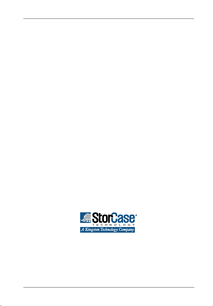
Inserting a Drive Carrier (without a Drive Installed)
Lift carrier handle while inserting drive carrier into chassis. Push down on carrier handle once
carrier is pushed all the way in. The carrier should latch into place if inserted correctly.
Lock the key lock to prevent unauthorized removal or installation of drive carrier.
Key
Lock
Carrier
Handle
Drive Carrier
IFS14_4
Figure 1: Drive Carrier
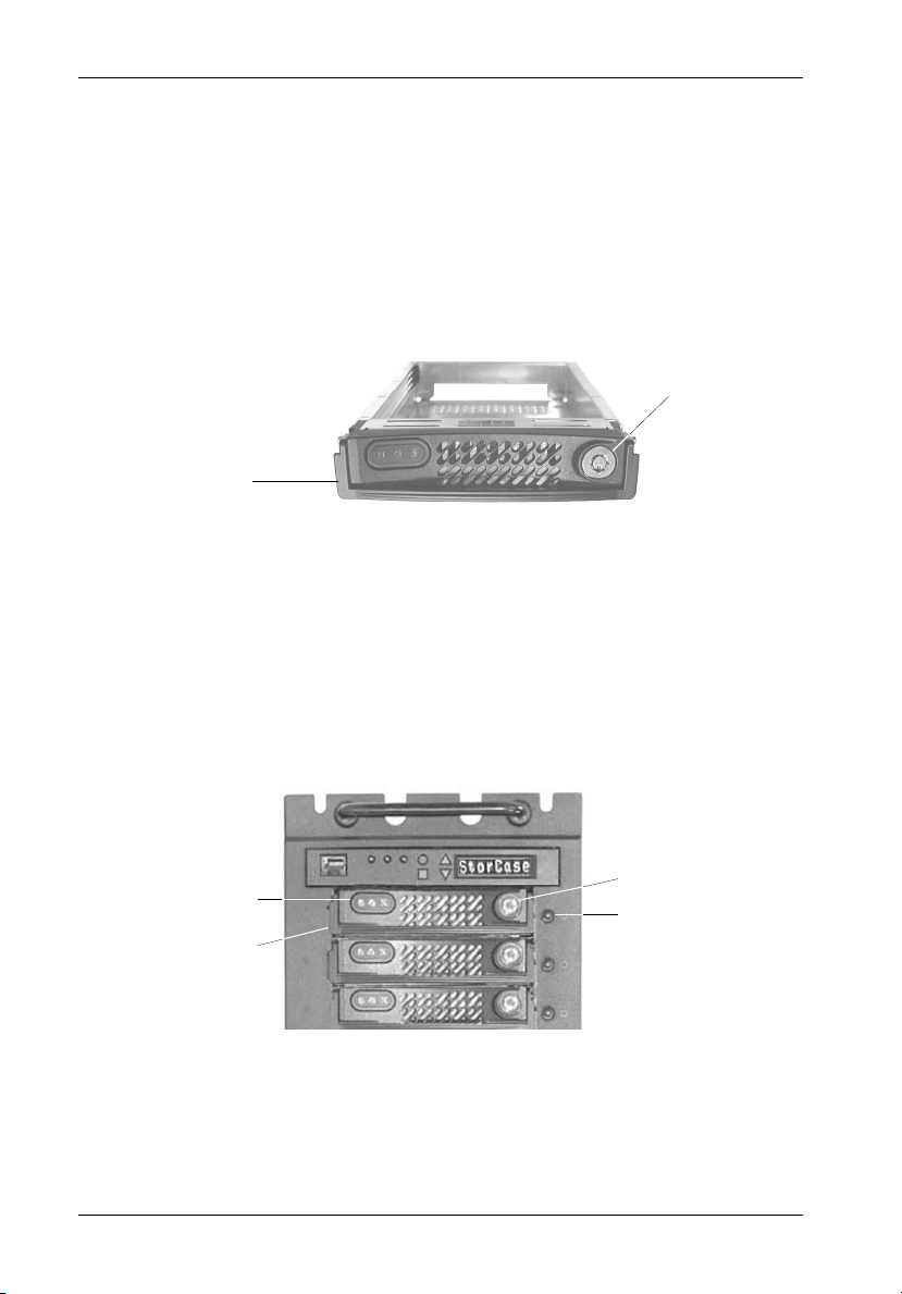
Drive Carrier Interface Panel
Each InfoStation drive carrier provides a User Interface for individual carrier operation (Figure
2).
Drive Carrier
LEDs
Drive Carrier
Handle
IFS14_18
Key Lock
Insert/Remove
Push Button
Figure 2: Drive Carrier Interface
StorCase Technology, Inc. InfoStation 14-Bay Installation Guide - Rev. C00
Page 8
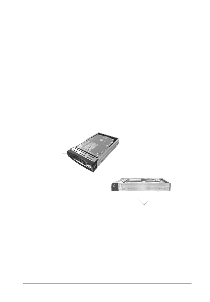
Installation 3
#6-32 Phillips
Pan Hd. Screw
(2 on each side)
IFS14_9
Installing a Drive into the Drive Carrier
NOTE: Before installing the drive into the carrier, the ID jumpers and spin-up option
jumper on the disk drive must be removed. This is required so that the
InfoStation itself can set the drive SCSI ID and spin-up option.
1. Install the drive(s) into the drive carrier(s). Drive(s) must be side-mounted into the
drive carrier(s) using #6-32 Phillips Pan Hd. screws (Figure 3).
2. After the drive(s) have been installed in to the drive carrier(s), carefully insert the
carrier(s) back into the chassis (refer to section "Inserting a Drive into the Chassis"
for further information).
Ultra160
SCA Drive
(Not Included)
Drive
Carrier
IFS14_8
Figure 3: Drive Installation
InfoStation 14-Bay Installation Guide - Rev. C00 StorCase Technology, Inc.
Page 9

4 Installation
Inserting a Drive into the Chassis
NOTES: A new drive can be inserted into an empty bay at anytime. However, the
1. Press and hold the Insert/Remove button (Figure 2) in until the Drive Ready LED
starts to flash (approximately 3 seconds).
2. Drive is ready to be accessed when the Drive Ready LED glows instead of flashes.
drive will not be ready for access until the following procedure is
followed.
The key lock is only to prevent unauthorized removal or installation of the
drive carrier. Locking the key lock is not required for drive carrier
operation.
Removing a Drive from the Chassis
(Refer to section "Drive Carrier Interface" in the InfoStation User's Guide for further information)
NOTE: Proper procedure must be followed when removing a drive from the drive
1. Press and hold the Insert/Remove button (Figure 2) in until the Drive Ready LED
starts to flash (approximately 3 seconds).
bay. It is the responsibility of the User to ensure that the host does not
access the drive while attempting to remove the drive, and to follow the
procedure outlined below. Failure to do so may result in loss of data and/
or damage to the drive itself!
2. Drive is ready to be removed when the Drive Ready LED is OFF.
3. Unlock the key lock (if locked) and remove the drive carrier by pulling on carrier handle
StorCase Technology, Inc. InfoStation 14-Bay Installation Guide - Rev. C00
(Figure 1).
Page 10

Installation 5
Removing the Blower Module
CAUTION: The blower module contains NO USER SERVICEABLE PARTS inside the
unit. Warranty is VOID if module is opened. Refer ALL servicing to
qualified service personnel!
WARNING: DO NOT USE MODULE HANDLES TO LIFT CHASSIS! These handles are
specifically designed for the installation and removal of modules only!
NOTE: The blower module is hot-swappable. The chassis may remain on when
removing and installing the blower module.
1. Loosen the captive pan head screw securing the blower module to the InfoStation
chassis (Figure 4).
2. Remove the blower module by grasping handle and pulling out from chassis.
3. To reinstall blower module, simply reverse above mentioned steps.
NOTE: Blank plate (provided) must be installed if module slot is left empty. Instal-
lation of the blank plate is necessary for proper cooling inside chassis.
Captive
Screw
Module
Handle
Blower
Module
IFS14_6
Figure 4: Removing the Blower Module
InfoStation 14-Bay Installation Guide - Rev. C00 StorCase Technology, Inc.
Page 11

6 Installation
Removing the Power Supply Module
CAUTION: The power supply module contains NO USER SERVICEABLE PARTS inside
the unit. Warranty is VOID if module is opened. Refer ALL servicing to
qualified service personnel!
NOTE: The power supply module is hot-swappable. The chassis may remain on
when removing and installing the power supply module.
1. Turn OFF power to the power supply module via the power switch located on the
module itself.
2. Loosen the locking thumbscrew securing the power supply module to the InfoStation
chassis (Figure 5).
3. Remove the power supply module by grasping handle outwards and pulling out from
chassis.
NOTE: Make sure the retainer clip (if installed) is not blocking the power supply
module handle (handle pivots outward). Damage to the retainer clip may
occur otherwise.
4. To reinstall power supply module, simply reverse above mentioned steps.
NOTE: Blank plate (provided) must be installed if module slot is left empty. Instal-
lation of the blank plate is necessary for proper cooling inside chassis.
IFS14_7
Locking
Thumbscrew
Handle
Power Supply
Module
Figure 5: Removing the Power Supply Module
StorCase Technology, Inc. InfoStation 14-Bay Installation Guide - Rev. C00
Page 12

Installation 7
Installing the Power Cord Retainer Clip
NOTE: Turn OFF power supply module and unplug power supply cord before
installing retainer clip (included in the InfoStation accessory packet).
1. Turn OFF power to the power supply module via the power switch located on the
module itself. If plugged in, unplug the power cord from the module.
2. Squeeze the retainer clip (Figure 6) and install onto the power supply module (as
shown in Step 1 of Figure 7).
3. Flip the retainer clip up and plug in the power cord (as shown in Step 2 of Figure
7).
4. Once cord is plugged in, push down the retainer clip so that it locks onto the power
cord (as shown in Step 3 of Figure 7).
IF14_23
Figure 6: Power Cord Retainer Clip
InfoStation 14-Bay Installation Guide - Rev. C00 StorCase Technology, Inc.
Page 13

8 Installation
1
Power Supply
Module
Retainer
Clip
3
2
IFS14_24
Retainer
Clip
AC Power
Cord
Retainer
Clip
AC Power
Cord
Figure 7: Installing the Power Cord Retainer Clip
NOTE: When removing the power supply module, make sure the retainer clip (if installed)
is not blocking the power supply module handle (handle pivots outward).
Damage to the retainer clip may occur otherwise.
StorCase Technology, Inc. InfoStation 14-Bay Installation Guide - Rev. C00
Page 14

Installation 9
Removing and Installing the I/O Module
(Procedure and information below applies to both the I/O Module and I/O Repeater Module)
CAUTION: Remove ALL power from the InfoStation before removing the I/O module.
The I/O module contains NO USER SERVICEABLE PARTS inside the unit.
Refer ALL servicing to qualified service personnel!
VHDCI connectors are easily damaged by improper handling. Visually
inspect each connector for bent contacts and carefully align prior to
insertion.
NOTES: The I/O module is NOT hot-swappable! Remove ALL power to chassis
before removing and installing the I/O module.
Optional I/O interfaces are available as an upgrade. Contact StorCase for
further ordering information.
1. Unplug the InfoStation and verify that ALL cables have been disconnected.
2. Place the InfoStation on a soft clean surface to protect finish of the chassis.
3. Loosen and remove the two (2) #6-32 Phillips F. H. screws securing the I/O
module to the InfoStation chassis (Figure 8).
4. Remove the I/O module by grasping handle and pulling out from chassis.
5. To reinstall I/O module, simply reverse above mentioned steps.
NOTE: Blank plate (provided) must be installed if module slot is left empty. Instal-
lation of the blank plate is necessary for proper cooling inside chassis.
#6-32 Phillips
Flat Hd. Screw
(2 Total)
Module
Handle
IFS14_10
Figure 8: Removing and Installing the I/O Module
InfoStation 14-Bay Installation Guide - Rev. C00 StorCase Technology, Inc.
Page 15

10 Installation
Removing the InfoStation Access Panel
CAUTION: Remove ALL power from the InfoStation before removing the access
panel(s). The InfoStation contains NO USER SERVICEABLE PARTS
inside the unit. Warranty is VOID if any of the modules inside the
InfoStation are opened. Refer ALL servicing to qualified service
personnel!
1. Unplug the InfoStation and verify that ALL cables have been disconnected.
2. Place the InfoStation on a soft clean surface to protect finish of the chassis.
3. Remove the ten (10) #6-32 Phillips F. H. screws securing the access panel to the
InfoStation chassis (Figure 9).
NOTE: Remove the access panel located on the RIGHT SIDE (Top) of the chassis
only.
4. Remove the access panel by carefully lifting the panel(s) off the chassis (Figure 9).
5. To reinstall panel, simply reverse the above mentioned steps.
#6-32 Phillips
Flat Hd. Screw
(10 total)
Access Panel
(Right Side)
InfoStation
Chassis
IFS14_19
Figure 9: Removing the Access Panel
StorCase Technology, Inc. InfoStation 14-Bay Installation Guide - Rev. C00
Page 16

Installation 11
Figure 10 below shows the inside of the InfoStation chassis (single-channel configuration)
with the access panel removed.
I/O
Module
Jumper
Block
Jumper
Block
Jumper
Block
Terminator
Block
IFS14_20
Figure 10: Single-Channel Backplane Configuration
InfoStation 14-Bay Installation Guide - Rev. C00 StorCase Technology, Inc.
Page 17

12 Installation
Configuring the InfoStation for Dual-Channel
CAUTION: Remove ALL power from the InfoStation before removing the I/O module.
The I/O module contains NO USER SERVICEABLE PARTS inside the unit.
Refer ALL servicing to qualified service personnel!
NOTE: Optional I/O interfaces are available as an upgrade. Contact StorCase for
further ordering information.
1. Unplug the InfoStation and verify that all cables have been disconnected.
2. Place the InfoStation on a soft clean surface to protect finish of the chassis.
3. Loosen and remove the two (2) #6-32 Phillips F. H. screws securing the I/O blank
plate to the InfoStation chassis (Figure 11). Correct dual-channel rear configuration
is shown in Figure 12.
4. Remove the I/O blank plate.
5. Remove access panel (as described on page 10).
6. Remove the center jumper block so that the second I/O module and terminator can
be installed. Correct dual-channel backplane configuration is shown in Figure 13.
#6-32 Phillips
Flat Hd. Screw
(2 Total)
I/O Blank
Plate
IFS14_11
Figure 11: Removing the I/O Blank Plate
StorCase Technology, Inc. InfoStation 14-Bay Installation Guide - Rev. C00
Page 18

Installation 13
Module #2
(Channel 2)
Module #1
(Channel 1)
InfoStation Rear
Figure 12: Dual-Channel Rear Panel Configuration
I/O
Module
Jumper
Block
Terminator
Block
I/O
Module
IFS14_33
Jumper
Block
Terminator
Block
IFS14_21
Figure 13: Dual-Channel Backplane Configuration
InfoStation 14-Bay Installation Guide - Rev. C00 StorCase Technology, Inc.
Page 19

14 Installation
Configuring the InfoStation for 4-Channel
CAUTION: Remove ALL power from the InfoStation before removing the I/O module.
The I/O module contains NO USER SERVICEABLE PARTS inside the unit.
Refer ALL servicing to qualified service personnel!
NOTE: Optional I/O interfaces are available as an upgrade. Contact StorCase for
further ordering information.
1. Unplug the InfoStation and verify that ALL cables have been disconnected.
2. Place the InfoStation on a soft clean surface to protect finish of the chassis.
3. Loosen and remove the two (2) #6-32 Phillips F. H. screws securing each I/O blank
plate to the InfoStation chassis (Figure 11).
4. Remove all three (3) I/O blank plates.
5. Remove access panel (as described on page 10).
6. Remove all the jumper blocks so that I/O modules ( #2, 3, and 4) and terminators (#2,
3, and 4) can be installed. Correct 4-channel backplane configuration is shown in
Figure 14.
I/O
Module
Terminator
Block
I/O
Module
Terminator
Block
I/O
Module
Terminator
Block
I/O
Module
Terminator
Block
IFS14_22
Figure 14: 4-Channel Backplane Configuration
StorCase Technology, Inc. InfoStation 14-Bay Installation Guide - Rev. C00
Page 20

Installation 15
Dual RAID Controller Module Unit Installation
CAUTION: Remove ALL power from the InfoStation before installing the Dual RAID
NOTES: The installation, configuration, and use of the Dual RAID Controller Module
While performing the steps in this section, work on a soft surface to prevent excessive shock
to the RAID Controller Module and InfoStation chassis. Also refer to the manufacturer's
documentation provided with the drive(s). A #2 Phillips and a flat blade screwdriver will be
required.
Controller Module unit. The RAID Controller Module contains NO USER
SERVICEABLE PARTS inside. Warranty is VOID if module is opened.
Refer ALL servicing to qualified service personnel!
option for the StorCase InfoStation chassis requires a certain level of
expertise and experience on the part of the user/integrator. Since there
are many configuration options and variables (ie. host platforms, applications, etc), only general guidelines will be discussed in this User's Guide.
Refer to both the InfoStation User's Guide and InfoStation Dual RAID
Controller Module User's Guide for additional operating and installation
information. Also refer to the disk manufacturer's documentation for information regarding the disks.
Removing the InfoStation Module Option Cover Plate
CAUTION: Remove ALL power from the InfoStation before removing any panels or
cover plates. The InfoStation contains NO USER SERVICEABLE PARTS
inside the unit. Refer ALL servicing to qualified service personnel!
NOTE: Cover plate must be installed if module slot is left empty. Installation of the
1. Loosen and remove the four (4) #6-32 Phillips F. H. screws securing the module option
cover plate to the InfoStation chassis (Figure 15). Remove the cover plate (save the
cover plate and screws for future use).
2. To reinstall cover plate, simply reverse the above mentioned steps.
InfoStation 14-Bay Installation Guide - Rev. C00 StorCase Technology, Inc.
cover plate is necessary for proper cooling inside chassis.
Page 21

16 Installation
Module Option
Cover Plate
Phillips F.H. Screw
(4 Total)
IFS9_2
Figure 15: Removing the Module Option Cover Plate
Installing the Dual RAID Controller Module Unit
1. Carefully slide the Dual RAID Controller Module Unit into the chassis and tighten the
two (2) captive screws (Figure 16).
Captive
Screw
(2 Total)
Dual RAID Controller
Module Unit
InfoStation Chassis
IFS9_11
Figure 16: Installing the Dual RAID Controller Module Unit
StorCase Technology, Inc. InfoStation 14-Bay Installation Guide - Rev. C00
Page 22

Installation 17
Installing/Removing a Single RAID Controller Module
NOTE: Cover plate (provided) must be installed if a module slot is left empty. Installation of
the cover plate is necessary for proper cooling inside chassis.
1. To remove a Single RAID Controller Module, loosen the Locking Thumbscrew and
pull on handle to slide out the Single RAID Controller Module (Figure 17).
2. To install a Single RAID Controller Module, simply reverse above mentioned steps.
Secondary RAID
Controller Module
Handle
Locking
Thumbscrew
Primary RAID
Controller Module
InfoStation Chassis
IFS9_12
Figure 17: Installing/Removing a Single RAID Controller Module
(RAID Controller A Shown)
InfoStation 14-Bay Installation Guide - Rev. C00 StorCase Technology, Inc.
Page 23

18 Installation
Installing the RAID Battery Backup Unit(s) into the InfoStation
CAUTION: Remove ALL power from the InfoStation before installing the RAID
Battery Module(s). The RAID Controller Module unit contains NO USER
SERVICEABLE PARTS inside. Warranty is VOID if module is opened.
Refer ALL servicing to qualified service personnel!
Danger of explosion if the RAID battery is incorrectly replaced! Replace
only with the same or equivalent type recommended by the manufacturer.
Dispose of used batteries according to the manufacturer's instructions.
NOTE: While performing the steps in this section, work on a soft surface to
prevent excessive shock to the RAID Controller Module and InfoStation
chassis.
The Dual RAID Controller Module unit comes with two RAID Battery Backup Units (the Single
RAID Module unit only comes with one). The Battery Backup Unit (Figure 18) provides
writeback cache backup power to the RAID Controller Module unit should the power fail for
any reason.
IFSII_DR10
Figure 18: RAID Battery Backup Unit
To install the RAID Battery Backup Unit(s):
1. Loosen and remove the #6-32 Phillips F.H. screw securing the blank plate to the
Blower Module (Figure 18). Remove blank plate.
2. Install the RAID Battery Backup Unit into the blower module (Figure 19).
3. Tighten the thumbscrew to secure the Battery Backup Unit in place.
StorCase Technology, Inc. InfoStation 14-Bay Installation Guide - Rev. C00
Page 24

Installation 19
Blank
#6-32 Phillips
F.H. Screw
IFSII_DR8
Plate
Blower
module
Figure 19: Installation Location of RAID Battery Backup Unit
Blower
Module
IFSII_DR9
RAID Battery
Backup Unit
Thumbscrew
Figure 20: Installing the RAID Battery Backup Unit into the Blower Module
InfoStation 14-Bay Installation Guide - Rev. C00 StorCase Technology, Inc.
Page 25

20 Installation
If installing only one (1) RAID Battery Backup Unit (for use with the Single RAID Controller Module
unit), the Battery Backup Unit must be installed into the correct blower module. Refer to Figure
21 for correct Battery Backup Unit installation locations.
NOTE: In case of blower module failure, be sure to reinstall the RAID Battery
Backup Unit(s) into the replacement blower module!
Battery Location for
RAID Controller B
Battery Location for RAID Controller A
IFSII_DR11
NOTE: For Dual RAID Module configurations, install
battery backup units in each blower module
NOTE: For Single RAID Module
configurations, install
battery backup unit in this
blower module ONLY!
Figure 21: RAID Battery Backup Unit Installation Location
StorCase Technology, Inc. InfoStation 14-Bay Installation Guide - Rev. C00
 Loading...