

Page 1

StorCase® T echnology
InfoSt ation
12-Bay Ultra320-to-Serial ATA RAID
12-Bay FC-to-Serial ATA RAID
External Expansion Chassis
User's Guide
®
Page 2
StorCase® Technology
i
InfoSt ation
®
12-Bay Ultra320-to-Serial ATA
12-Bay FC-to-Serial ATA
RAID External Expansion Chassis
User's Guide
Part No. D89-0000-0249 D00 February 2006
StorCase Technology, Inc.
17600 Newhope Street
Phone (714) 438-1850 Fax (714) 438-1847
InfoStation 12-Bay RAID User's Guide - Rev. D00 StorCase Technology, Inc.
Fountain Valley, CA 92708-9885
Page 3

ii
LIMITED WARRANTY
STORCASE TECHNOLOGY, Incorporated (“StorCase”) warrants that its products will be free
from defects in material and workmanship, subject to the conditions and limitations set forth
below. StorCase will, at its option, either repair or replace any part of its product that proves
defective by reason of improper workmanship or materials. Repair parts or replacement
products will be provided by StorCase on an exchange basis, and will be either new or
reconditioned to be functionally equivalent to new.
This warranty does not cover any product damage that results from accident, abuse, misuse,
natural or personal disaster, external power surge or failure, or any unauthorized disassembly, repair or modification. StorCase will not be responsible for any software, firmware or other
customer data stored within, or interfacing with a StorCase product.
Duration of Warranty
Seven-Year Warranty: The following StorCase products are covered by this warranty for a
period of seven (7) years from the original date of purchase from StorCase or its authorized
resellers: all Data Express® removable device enclosures and all Data Silo®, Data Stacker® and
InfoStation® external expansion chassis, except for those components integrated into or
purchased separately for use with these products which are identified and covered by the threeyear or hard drive warranties described below. All StorCase interface cables and other
accessories specifically intended for use with the StorCase products identified above are also
covered by this (7) year warranty.
Three-Year Warranty: The following components integrated into or purchased separately for
use with StorCase Data Express, Data Silo, Data Stacker and/or InfoStation products are subject
to warranty for a period of three (3) years from the original date of purchase from StorCase or
its authorized resellers: all RAID controllers, power supplies, fans and blowers.
Two-Year Warranty: The following StorCase products are covered by this warranty for a
period of two (2) years from the original date of purchase from StorCase or its authorized
resellers: all Rhino®JR fixed external expansion chassis (model types “FJR”) and all RhinoJR
removable device enclosures (model types “RJR”).
One-Year Warranty: All StorCase products identified as Reconditioned or “Special Inventory”
are covered by this warranty for a period of one (1) year from the original date of purchase from
StorCase or its authorized resellers. Reconditioned products may only be exchanged for
reconditioned products.
Hard Disk Drive Warranty: All hard disk drives purchased from StorCase or through its
authorized resellers, whether purchased separately or integrated into StorCase products, are
subject to the warranty terms and conditions provided by the drive manufacturer.
Third Party Software Warranty: All third party software purchased from StorCase for use
with and/or as part of StorCase products is subject to the warranty terms and conditions
provided by the software manufacturer.
StorCase Technology, Inc. InfoStation 12-Bay RAID User's Guide - Rev. D00
Page 4

Warranty Claim Requirements
To obtain warranty service, the defective product must be returned to your local authorized
StorCase dealer or distributor, or, with prior StorCase approval, to the StorCase factory
service center.
For defective products returned directly to StorCase, a Return Material Authorization (“RMA”)
number must be obtained by calling StorCase Customer Service at (714) 445-3455. The RMA
number must be prominently displayed on the outside of the return package. Shipments must
be freight-prepaid and insured, and must include the product serial number, a detailed
description of the problem experienced, and proof of the original retail purchase date. Products
must be properly packaged to prevent damage in transit. Damage resulting from improper
packaging will not be covered by this warranty. The StorCase factory service center is located
at 17650 Newhope Street, Receiving Dock, Gate #4, Fountain Valley, CA 92780, U.S.A.
Free Technical Support
StorCase provides free technical support. If you experience any difficulty during the
installation or subsequent use of a StorCase product, please contact StorCase’s Technical
Support Department prior to servicing your system. This warranty covers only repair or
replacement of defective StorCase products, as described above. StorCase is not liable for,
and does not cover under warranty, any costs associated with servicing and/or installation
of StorCase products.
StorCase Technical Support can be reached in the U.S. at (714) 438-1858 or toll-free at (888)
435-5460 (U.S. and Canada only). StorCase European Technical Support can be reached in
the U.K. at +44 (0) 1932 738900.
iii
Disclaimers
The foregoing is the complete warranty for the products identified above and
supersedes all other warranties and representations, whether oral or written.
StorCase expressly disclaims all warranties for the identified products, which are
not stated herein, including, to the extent permitted by applicable law, any implied
warranty of merchantability or fitness for a particular purpose. In no event will
StorCase be liable to the purchaser, or to any user of a StorCase product, for any
damages, expenses, lost revenues, lost savings, lost profits, or any other
incidental or consequential damages arising from the purchase, use or inability
to use a StorCase product, even if StorCase has been advised of the possibility
of such damages.
Copyright © 2004 StorCase Technology. All rights reserved. All registered
trademarks are the property of StorCase Technology. All other logos and trademarks
are properties of their respective companies.
InfoStation 12-Bay RAID User's Guide - Rev. D00 StorCase Technology, Inc.
Page 5
iv
Declaration of Conformity
Company Name:
Corporate Office Address:
Manufacturing Address:
Product Name:
Model Number:
Conforms to the following standards:
EMC Directives:
(89/336/EEC)
Low Voltage Directive:
(73/23/EEC)
Safety Standards:
CSA (NRTL/C)
StorCase Technology, Inc.
17600 Newhope Street
Fountain Valley, CA 92708
17600 Newhope Street
Fountain Valley, CA 92708
InfoStation 12-Bay SCSI-to-SATA RAID Chassis
InfoStation 12-Bay FC-to-SATA RAID Chassis
S10B100, S10J100, S10H104, S10H105, S10H108,
S10H112, S10K102, S10K104
ITE Emission
- EN 55022: 1998
- EN 61000-3-2 Harmonic Current
- EN 61000-3-3 Voltage Fluctuations and Flicker
EN 55024: 1998 ITE Immunity
- IEC 61000-4-2 - IEC 61000-4-5
- IEC 61000-4-3 - IEC 61000-4-6
- IEC 61000-4-4 - IEC 61000-4-8
- IEC 61000-4-11
EN 60950
CAN/CSA-C22.2 No. 60950
UL 60950, Third Edition
TUV
EMI Standards:
EMC Standards:
Year of Manufacture:
Signature:___________________
Full name: Dieter Paul
Position: President
StorCase Technology, Inc. InfoStation 12-Bay RAID User's Guide - Rev. D00
EN 60950: 2000
FCC Part 15, Class A
AS/NSZ 3548 Information Technology Equipment
Supplier's Code Number N10664
2004
Page 6

Federal Communications Commission (FCC) Statement
RADIO FREQUENCY INTERFERENCE STATEMENT
You are cautioned that changes or modifications not expressly approved by the party
responsible for compliance could void your authority to operate that equipment.
This device complies with part 15 of the FCC rules. Operation is subject to the following two
conditions: (1) This device may not cause harmful interference, and (2) This device must
accept any interference received, including interference that may cause undesired operation.
Important Safety Instructions
1. Read all these instructions.
2. Save these instructions for later use.
3. Follow all warnings and instructions marked on the product.
4. Do not use this product near water.
5. This product should be operated from the type of power source indicated on the
marking label. If you are not sure of the type of power available, consult your dealer
or local power company.
6. Do not attempt to service this product yourself, as opening or removing covers may
expose you to dangerous voltage points or other risk. Refer all servicing to service
personnel.
v
Wichtige Sicherheitshinweise
1. Diese Hinweise sollten vollständig durchgelesen werden.
2. Diese Hinweise für einen späteren Gebrauch aufbewahren.
3. Allen auf dem Gerät angebrachten Warnungen und Hinweisen folgen.
4. Das Gerät nicht in der Nähe von Wasser verwenden.
5. Das Gerät nur mit dem Aufkleber bezeichneten Netzspannung betreiben. Bei Fragen
über die Art der Netzspannung sollte der Händler oder das
Energieversorgungsunternehmen zu rate gezogen werden.
6. Nicht versuchen das Produkt selbst zu reparieren. In allen Produkten existieren
gefährliche elektrische Spannugen. Nicht das Gehäuse öffnen.
7. Wartungsarbeiten nur von qualifiziertern Kundendienstpersonal ausführen laßen.
InfoStation 12-Bay RAID User's Guide - Rev. D00 StorCase Technology, Inc.
Page 7

vi
Table of Contents
INTRODUCTION ..................................................................................................................... 1
Packaging Information .................................................................................................. 1
Serial Number................................................................................................................ 1
General Description...................................................................................................... 2
Front Panel............................................................................................................ 5
Rear Panel............................................................................................................. 6
LED Indicator and User Interface Panel ...................................................................... 8
LED Indicator/UI Panel Components .................................................................... 8
Drive Carrier Interface Panel ............................................................................... 9
Inserting a Drice Carrier (with Drive Installed) ................................................. 10
Removing a Drive Carrier (with Drive Installed) ............................................... 10
Configuring Device and Chassis Settings ........................................................ 10
TYPICAL SCSI CHANNEL CONFIGURATION ..................................................................... 11
TYPICAL FIBRE CHANNEL CONFIGURATION.................................................................... 12
RAID CONTROLLER CONFIGURATION .............................................................................. 14
RAID Management Connection .................................................................................. 14
Configuring the RAID Controller ................................................................................. 16
RAID Configuration via Data Master GUI ................................................................... 17
Data Master Connection..................................................................................... 17
Quick RAID Setup ............................................................................................... 22
Customized RAID Setup ..................................................................................... 24
Partitions ............................................................................................................. 26
Partitions Greater than 2TB ....................................................................... 26
Setting Up Multiple Partitions...................................................................... 27
LUN Mapping ....................................................................................................... 32
Deleting an Array ............................................................................................... 35
RAID Configuration via HyperTerminal ...................................................................... 36
HyperTerminal Connection................................................................................. 36
To Find HyperTerminal in Windows........................................................... 36
Settings....................................................................................................... 36
Selecting Menu Options ............................................................................. 38
Quick RAID Setup ............................................................................................... 39
Customized RAID Setup ..................................................................................... 40
Partitions ............................................................................................................. 42
Partitions Greater than 2TB ....................................................................... 42
Viewing Default Partition Configuration .................................................... 42
Setting Up Multiple Partitions...................................................................... 43
LUN Mapping ....................................................................................................... 46
Deleting an Array ............................................................................................... 49
StorCase Technology, Inc. InfoStation 12-Bay RAID User's Guide - Rev. D00
Page 8

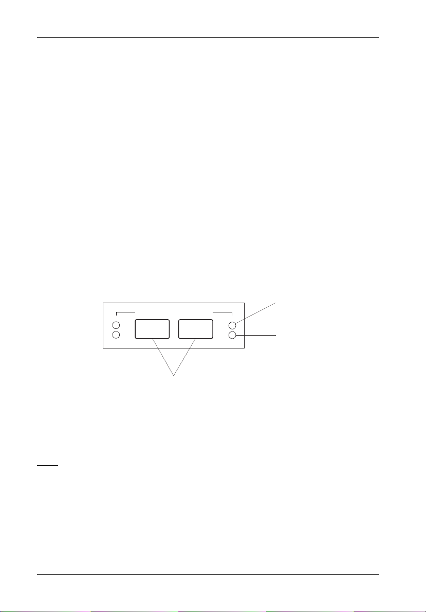
RAID Configuration via InfoStation RAID Control Panel ............................................ 50
RAID Control Panel ............................................................................................. 50
LEDs ................................................................................................................ 51
Control Panel Buttons..................................................................................... 51
Operation Mode .................................................................................................. 52
Mode Operation .................................................................................................. 53
Self-Diagnostic Mode ..................................................................................... 53
Configuration Mode ........................................................................................ 53
Entering a Password ..................................................................................... 53
Main Menu Options ............................................................................................. 54
Quick RAID Setup ............................................................................................... 55
Customized RAID Setup ..................................................................................... 56
Partitions ............................................................................................................. 58
Partitions Greater than 2TB ....................................................................... 58
Setting Up Multiple Partitions...................................................................... 58
LUN Mapping ....................................................................................................... 60
Deleting an Array ............................................................................................... 61
RAID Controller Configuration Overview .................................................................. 62
1 RAID Params................................................................................................... 62
1.1 Array 1 .................................................................................................... 63
1.1.1 Reconfigure RAID ............................................................................ 63
1.1.2 RAID Level........................................................................................ 63
1.1.3 Disk Number ..................................................................................... 63
1.1.4 Slice .................................................................................................. 64
1.2 - 1.8 Arrays 2-8 ...................................................................................... 64
1.9 Stripe Size ............................................................................................... 64
1.A Write Buffer ............................................................................................ 65
1.B Performance ........................................................................................... 65
vii
Array Management ............................................................................................. 66
RAID Levels .................................................................................................... 66
2 SCSI Params (SCSI-to-SATA version only) ................................................. 67
2.1 Primary SCSI............................................................................................ 67
2.1.1 Set SCSI ID ....................................................................................... 67
2.1.2 Speed ............................................................................................... 67
2.1.3 Wide.................................................................................................. 67
2.1.4 LUN Map ........................................................................................... 68
2.1.5 QAS .................................................................................................. 68
2.2 Secondary SCSI ...................................................................................... 68
2 Fibre Params (FC-to-SATA version only)..................................................... 69
2.1 Primary FC ............................................................................................... 69
2.1.1 Enable Hard Loop ID ........................................................................ 69
2.1.2 Set Hard Loop ID .............................................................................. 69
2.1.3 Set Connection Mode ...................................................................... 70
2.1.4 Set Data Rate ................................................................................... 70
2.1.5 LUN Map ........................................................................................... 70
2.2 Secondary FC ......................................................................................... 70
InfoStation 12-Bay RAID User's Guide - Rev. D00 StorCase Technology, Inc.
Page 9

viii
2.3 SAN Mask ................................................................................................ 70
2.3.1 Visible for All Hosts ......................................................................... 70
2.3.1.1 Port 1 ......................................................................................... 70
2.3.1.2 Port 2 ......................................................................................... 70
2.3.2 SAN Mapping ................................................................................... 71
2.3.2.1 Port 1 ......................................................................................... 71
2.3.2.1.1 - 2.3.2.1.8 Select Host ...................................................... 71
2.3.2.2 Port 2 ......................................................................................... 71
2.3.2.2.1 - 2.3.2.2.8 Select Host ...................................................... 71
2.3.3 Edit WWN Table................................................................................ 71
2.3.3.1 - 2.3.3.8 Select Host................................................................. 71
2.3.4 View WWN Table............................................................................. 71
2.3.5 View SAN Mapping .......................................................................... 72
2.3.5.1 Port 1 ......................................................................................... 72
2.3.5.2 Port 2 ......................................................................................... 72
3 RS232 Params................................................................................................ 73
3.1 Modem Port.............................................................................................. 73
3.1.1 Bau d R at e ......................................................................................... 73
3.1.2 Stop Bit ............................................................................................. 73
3.1.3 Data Bit ............................................................................................. 73
3.1.4 Parity................................................................................................. 73
3.2 Terminal Port............................................................................................ 74
3.2.1 Bau d R at e ......................................................................................... 74
3.2.2 Stop Bit ............................................................................................. 74
3.2.3 Data Bit ............................................................................................. 74
3.2.4 Parity................................................................................................. 74
4 System Params .............................................................................................. 75
4.1 Password Info ......................................................................................... 75
4.1.1 Password Check ............................................................................ 75
4.1.2 Set Password .................................................................................. 75
4.2 Pager Info ................................................................................................ 76
4.2.1 Paging ............................................................................................... 76
4.2.2 Pager 1 No. ...................................................................................... 77
4.2.3 Pager 2 No. ...................................................................................... 77
4.2.4 Code ................................................................................................. 77
4.2.5 Repeat .............................................................................................. 77
4.2.6 Interval.............................................................................................. 77
4.2.7 Page Now ......................................................................................... 77
4.3 Fax Info.................................................................................................... 78
4.3.1 Fax.................................................................................................... 78
4.3.2 Fax Class ......................................................................................... 78
4.3.3 Fax 1 No. .......................................................................................... 78
4.3.4 Fax 2 No. .......................................................................................... 79
4.3.5 Retry # .............................................................................................. 79
4.3.6 Fax Now ........................................................................................... 79
4.4 Company Info .......................................................................................... 79
4.4.1 String 1 ............................................................................................. 79
4.4.2 String 2 ............................................................................................. 80
StorCase Technology, Inc. InfoStation 12-Bay RAID User's Guide - Rev. D00
Page 10

4.5 Modem Init St ........................................................................................... 80
4.5.2 String 2 ............................................................................................. 80
5 NVRAM ........................................................................................................... 81
5.1 Update NVRAM ....................................................................................... 81
5.2 Erase NVRAM ......................................................................................... 81
5.3 Restart ..................................................................................................... 81
6 RAID Functions............................................................................................... 82
6.1 Init Parity .................................................................................................. 83
6.2 Parity Check ............................................................................................ 83
6.3 Beeper ..................................................................................................... 83
6.4 Stop Modem............................................................................................. 83
6.5 Add Disk .................................................................................................. 83
6.6 Remove Disk............................................................................................ 83
6.7 Statistic .................................................................................................... 84
6.8 Expand Array .......................................................................................... 84
6.9 Update ROM ............................................................................................ 84
6.9 Log Event................................................................................................. 84
6.9.1 Erase ................................................................................................ 84
6.9.2 Statistic ............................................................................................. 84
6.9.3 RTC ................................................................................................... 85
6.9.3.1 Set RTC ..................................................................................... 85
6.9.3.2 Show RTC................................................................................. 85
6.A Utility ........................................................................................................ 85
6.A.1 Disk Self-Test (DST) ....................................................................... 85
6.A.1.1-6.A.1.2 Short Self Test or Extended Self Test ...................... 85
6.A.1.3 Stop DST .................................................................................. 86
6.A.2 Disk Scrubbing ................................................................................ 86
6.A.2.1 Overwrite Parity ...................................................................... 86
6.A.2.2 Scrub Mode .............................................................................. 86
6.A.2.2.1 Manual Scrubbing ............................................................. 86
6.A.2.2.2 Schedule Scrubbing ......................................................... 87
6.A.2.2.3 View Schedule ................................................................. 87
6.A.3 Disk Clone ........................................................................................ 87
6.A.3.1 Start Disk Clone ....................................................................... 87
6.A.3.1.1-6.A.3.1.2 Source Disk and Target Disk........................... 88
6.A.3.1.3 Start Permanent Clone...................................................... 88
6.A.3.1.4 Start Swap after Clone .................................................... 88
6.A.3.2 Stop Disk Clone........................................................................ 88
6.A.3.3 Replace Source Disk ............................................................... 88
6.A.4 SMART ............................................................................................. 88
6.A.4.1 Test Disk SMART ..................................................................... 89
6.A.4.2 SMART Mode............................................................................ 89
6.A.4.3 SMART Check Time ................................................................. 89
6.A.4.4 Bad Blocks ............................................................................... 89
6.A.4.4.1 View Statistics ................................................................. 89
6.A.4.4.2 Threshold for Clone .......................................................... 90
6.A.4.4.3 Threshold for Swap ......................................................... 90
6.B Update Rom............................................................................................. 90
ix
InfoStation 12-Bay RAID User's Guide - Rev. D00 StorCase Technology, Inc.
Page 11

x
APPENDICES........................................................................................................................ 91
Appendix A - Specifications/Dimensions .................................................................. 92
Appendix B - Optional Accessories .......................................................................... 97
Slide Rail Kit......................................................................................................... 98
RAID Controller Memory Modules ...................................................................... 99
Optional Power Supply Module........................................................................ 100
Replacement Fan Module ................................................................................. 101
Drive Carrier...................................................................................................... 102
SFP Module (For FC-to-SATA version only)................................................... 102
Carrying Case ................................................................................................... 103
RAID Battery Backup Kit .................................................................................. 104
InfoStation Monitoring Utility (InfoMon) ............. ... ............................................ 105
Appendix C - Troubleshooting ................................................................................. 106
StorCase Technical Support ............................................................................ 106
Setup Problems................................................................................................. 106
Operation Problems .......................................................................................... 107
Remote Terminal Problems............................................................................... 108
Alert Message Problems .................................................................................. 108
SCSI Problems .................................................................................................. 109
Error Messages ................................................................................................ 110
Reader's Comments.......................................................................................................... 113
StorCase Technology, Inc. InfoStation 12-Bay RAID User's Guide - Rev. D00
Page 12

List of Figures
Figure 1: InfoStation 12-Bay RAID Chassis.................................................................. 4
Figure 2: InfoStation Front Panel ................................................................................... 5
Figure 3A: SCSI-to-SATA InfoStation Rear Panel .......................................................... 7
Figure 3B: FC-to-SATA InfoStation Rear Panel .............................................................. 7
Figure 4: UI Module......................................................................................................... 8
Figure 5: InfoStation Drive Carrier Interface ................................................................ 9
Figure 6: Typical Dual SCSI Host Connection to InfoStation ...................................... 11
Figure 7: FC Ports and LEDs ....................................................................................... 12
Figure 8: Typical Dual FC Loops Connection to InfoStation ...................................... 13
Figure 9: DB9 Port Location......................................................................................... 15
Figure 10A: Connection Name Setup Screen ................................................................. 17
Figure 10B: Connection Screen ...................................................................................... 18
Figure 10C: Location Type Setup Screen ....................................................................... 19
Figure 10D: Serial Port Setup Screen ............................................................................. 19
Figure 10E: Baud Rate Setup Screen ............................................................................. 20
Figure 10F: Set Access Screen ..................................................................................... 20
Figure 10G: Password Screen........................................................................................ 21
Figure 10H: Confirmation Screen .................................................................................... 21
Figure 11: Data Master Quick Setup Screen ................................................................ 22
Figure 12: Data Master RAID Creation Screen ............................................................. 23
Figure 13: Data Master Create Array Option................................................................ 24
Figure 14: Data Master Create Array Screen .............................................................. 25
Figure 15: Data Master Partitions Option ...................................................................... 27
Figure 16: Data Master Create Partitions Screen ........................................................ 28
Figure 17: Data Master Reconfigure Partitions Option................................................. 29
Figure 18A: Example of a RAID 0 Creation with 2.2TB Total Capacity ......................... 30
Figure 18B: Example of a RAID 0 Creation with 2.2TB Total Capacity ......................... 31
Figure 19: Data Master LUN Mapping Option................................................................ 32
Figure 20A: Example of One Array and One Partition.................................................... 33
Figure 20B: Example of Two Arrays and Two Partitions .............................................. 34
Figure 21A: HyperTerminal Connection Screen.............................................................. 37
Figure 21B: Monitor Utility (HyperTerminal) Screen ....................................................... 37
Figure 22: Example of a RAID 0 Creation with 2.2TB Total Capacity ......................... 45
Figure 23: HyperTerminal LUN Map Option ................................................................... 47
Figure 24: Example of One Array and Two Slices ...................................................... 48
Figure 25: LCD Display and Control Panel .................................................................... 50
xi
Figure A-1: InfoStation Physical Dimensions .................................................................. 97
Figure B-1: Rack Mount Slide Rail Kit.............................................................................. 98
Figure B-2: RAID Controller Memory Module .................................................................. 99
Figure B-3: Power Supply Module ................................................................................ 100
Figure B-4: Fan Module ................................................................................................. 101
Figure B-5: Drive Carrier ............................................................................................... 102
Figure B-6: LC (optical) SFP Module ............................................................................. 102
Figure B-7: Carrying Case ............................................................................................. 103
Figure B-8: RAID Battery Backup Kit ............................................................................ 104
InfoStation 12-Bay RAID User's Guide - Rev. D00 StorCase Technology, Inc.
Page 13

xii
List of Tables
Table 1: Drive Carrier Interface Components ................................................................... 9
Table 2: Communications Parameters ............................................................................. 15
Table 3: Selecting Menu Options ..................................................................................... 38
Table 4: LCD Display Components................................................................................... 51
Table 5: Main Menu Options ............................................................................................. 54
Table 6: RAID Level Comparisons ................................................................................... 66
Table 7: SCSI Set-Up ........................................................................................................ 68
Table C-1: Error Messages ................................................................................................ 110
NOTICE: This User's Guide is subject to periodic updates without notice. While reason-
StorCase Technology, Inc. InfoStation 12-Bay RAID User's Guide - Rev. D00
able efforts have been made to ensure accuracy of this document, Storcase
Technology, Inc. assumes no liability resulting from errors or omissions in this
publication, or from the use of the information contained herein.
Please check the StorCase web site at http://www.storcase.com or contact
your StorCase representative for the latest revision of this document.
Page 14

Introduction 1
INTRODUCTION
Packaging Information
The StorCase Technology InfoStation external expansion chassis is shipped in a container
designed to provide protection and prevent damage during shipment, as confirmed by the
International Safe Transit Association (ISTA Procedure 1A). The InfoStation was carefully
inspected before and during the packing procedure at the factory. Evidence of any damage
to the InfoStation should be reported to the shipper immediately.
If the wrong InfoStation model has been received, please call your reseller or StorCase at
(800) 435-0642 to arrange for a Return Material Authorization (RMA). StorCase cannot accept returns which do not display an RMA number on the outside of the package. Return the
unit with all the original packing materials.
Before removing any component from its packaging, discharge any static electricity by
touching a properly grounded metal object.
Serial Number
The InfoStation is labeled with a serial number. This number must be reported to the StorCase
Customer Service Representative in order to receive a Return Material Authorization (RMA)
for warranty claims. Locate the serial number label and record the number in the space
provided below.
InfoStation Serial Number:
InfoStation 12-Bay RAID User's Guide - Rev. D00 StorCase Technology, Inc.
Page 15

2 Introduction
General Description
CAUTION: The InfoStation chassis contains NO USER SERVICEABLE parts inside the unit.
NOTES: The configuration and use of the InfoStation RAID Controller requires a certain
High performance InfoStation 12-bay SCSI-to-Serial ATA and FC-to-Serial ATA RAID enclosures are designed to support low-profile Serial ATA (SATA) or Parallel ATA (Ultra ATA/100)
drives for RAID applications. The SCSI-to-SATA enclosures (P/Ns S10H108 & S10H112)
support dual SCSI Ultra320 host channels and are downward-compatible with earlier SCSI
Wide Single-Ended or LVD interface technologies (i.e. Ultra2 or Ultra). Daisy-chaining chassis
for extended storage is also possible with optionally available SCSI Ultra320 repeater kits. The
FC-to-SATA enclosures (P/Ns S10K102 & S10K104) support dual Fibre Channel Arbitrated
Loops (FC-ALs) with 2Gbps operation.
Each standard 4U rack mount 12-bay RAID InfoStation chassis comes equipped with a RAID
controller, (12) removable drive carriers and an open 5.25" half-height device bay. These
enclosures are constructed of corrosion-resistant steel and each include (2) hot-swappable,
redundant 460W power supply modules and (2) hot-swappable, redundant, variable-speed
fan modules.
Both the SCSI-to-SATA and FC-to-SATA RAID chassis support RAID levels 0, 1, 0+1, 3, 5, 30,
and 50, and is OS independent. Online Capacity Expansion (OCE) and LUN support, up to
1GB DDR PC2100 SODIMM cache memory, as well as automatic hot swap, hot spare and
drive rebuild support are all included. An audible alarm on the InfoStation alerts the User to
system hardware failures and warning conditions. LED indicators at each drive bay provide
additional User feedback for drive activity, drive readiness and drive faults.
Refer ALL servicing to qualified personnel!
level of expertise and experience on the part of the user/integrator. Since there
are many configuration options and variables (ie. host platforms, applications,
etc.), only general guidelines will be discussed in this User's Guide.
Refer to the disk manufacturer's documentation for specific information regarding the disks.
The InfoStation also incorporates "Soft Start" circuitry which eliminates in-rush current to each
of the installed drives during spin-up, as well as avoid power arcing during drive insertion.
A User Interface Module on the 12-bay InfoStation provides the User with a visual indication
of chassis configurations and communication statuses, in addition to providing an RS232
connection for system environmental monitoring, configuration and control. InfoMon®, a
downloadable chassis monitoring utility program, provides the InfoStation with a customizable,
web-based monitoring capability via the RS-232 serial connection. InfoMon includes a “Call
Home” feature, which enables chassis log information to be conveniently sent to a predetermined FTP site for trouble shooting and analysis. InfoMon also provides the User the ability to
easily configure both device and chassis settings with a few clicks of the mouse! Refer to
Appendix B for further information on InfoMon.
StorCase Technology, Inc. InfoStation 12-Bay RAID User's Guide - Rev. D00
Page 16

Introduction 3
The latest versions of the InfoMon utility program and User's Guide can be downloaded (free
of charge) from the StorCase web site (http://www.storcase.com). Contact StorCase for
further information. Refer to Appendix B for further information on optional InfoStation
accessories.
Using a modular approach supported by redundant features and hot swapping capabilities,
the InfoStation will provide continued data availability and allow for ease of maintenance and
minimal system down time.
The modular and scalable design of the InfoStation chassis also allows a variety of future
product upgrades to be offered. Upgrade modules are anticipated InfoStation options.
This User's Guide describes the steps required for installing drive(s) into the InfoStation
external expansion chassis. This guide is intended to supplement documentation provided with
the host computer system, the operating system, and the drive(s) to be installed within the
InfoStation.
Features:
• 4U Rack Mount Chassis
• One (1) 5.25" half-height bay (for canister-type SCSI device)
• Supports dual SCSI Ultra320 host channels (SCSI-to-SATA version only)
• Supports dual FC-ALs (FC-to-SATA version only)
• Supports either twelve (12) Serial ATA or Ultra ATA/100 drives
• Supports RAID levels 0, 1, 0+1, 3, 5, 30, 50
• Supports 8 arrays and 128 LUNs
• Corrosion-resistant steel construction
• Two (2) 460W hot-swappable power supply modules
• Two (2) hot-swappable variable-speed fan modules
• Audible alarm
• Status indicators at each bay
• "Soft Start" circuitry
• Web-based monitoring utility (InfoMon)
• Data Master® Storage Manager GUI
• Online Capacity Expansion (OCE)
• Hot spare and automatic drive rebuild
• Fax/Pager notification
• OS independent (no software or special drivers required)
• RS-232 connector for system environmental monitoring, configuration, and control
• 128MB PC2100 DDR SODIMM memory
• 7-year limited warranty* and free 24/7 technical support
* 3-year limited warranty on RAID controller and Power & Cooling Modules
InfoStation 12-Bay RAID User's Guide - Rev. D00 StorCase Technology, Inc.
Page 17
4 Introduction
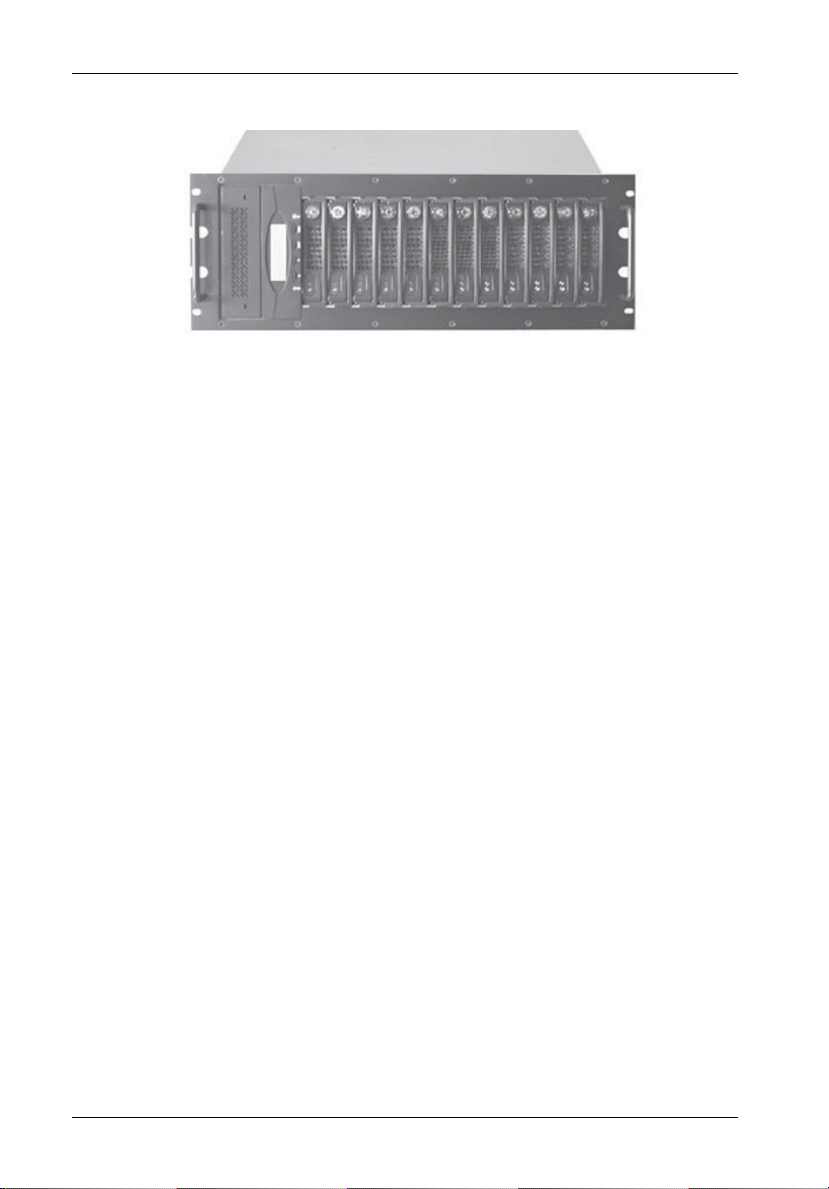
Figure 1: InfoStation 12-Bay RAID Chassis
StorCase Technology, Inc. InfoStation 12-Bay RAID User's Guide - Rev. D00
Page 18
Introduction 5
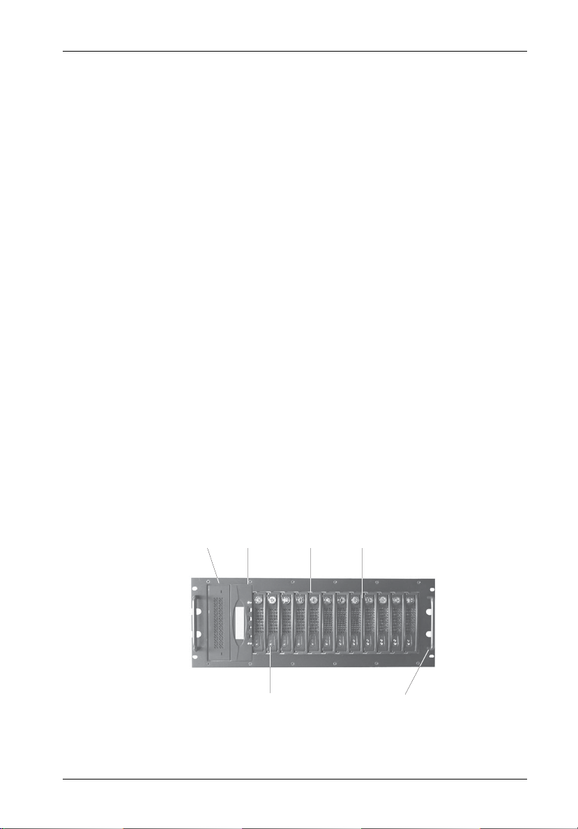
Front Panel
(Figure 2)
• 5.25" Bay - One bay can accommodate one (1) half-height SCSI device.
• RAID Control Panel - Refer to Figure 8.
• Drive Carrier(s) - Accommodate up to twelve (12) 3.5" low-profile Parallel ATA or
Serial ATA devices. Backplane design eliminates cable connections to drives,
increases data integrity, and supports drive hot swappability.
• Drive Carrier LED(s) - Provides the following information:
Drive Ready (Blue) - Indicates that the drive is properly installed and ready
Drive Fault (Red) - Indicates a drive failure.
Drive Activity (Amber) - Indicates that the drive is being accessed.
Refer to Figure 5 & Table 1 for further information.
• Key Lock(s) - Assure proper seating of the drive carrier within the chassis and
prevent unauthorized removal or installation of the carrier.
for access.
NOTE: The key lock is only to prevent unauthorized removal or installation of the
drive carrier. Locking the key lock is not requried for drive carrier operation.
• Chassis Handle(s) - Provide a sturdy grip for the installation and removal of the
rack-mount chassis.
5.25
Bay
Panel
Drive Carrier
Drive Carrier
LEDs
Handle
Key
Lock
Chassis
Handle
RAID
Control
Figure 2: InfoStation Front Panel
InfoStation 12-Bay RAID User's Guide - Rev. D00 StorCase Technology, Inc.
Page 19

6 Introduction
Rear Panel
(Figure 3)
NOTE: Blank plate (provided) must be installed if any module slot is left empty. Instal-
• UI Module - LED panel displays system statuses, alarms, and warnings. Refer to
• I/O Panel - Provides two (2) DB9 connectors for RS-232 and Modem, and two (2)
• Power Supply Module(s) - Two (2) 460W redundant, hot swappable power
lation of the blank plate is necessary for proper cooling inside chassis.
section "User Interface Module" for further information.
HD68 I/Os for SCSI Host channels (SCSI-to-SATA version only) or two (2) FC ports
for dual FC-ALs (FC-to-SATA version only). Also provides space for up to four (4)
extra I/Os if desired.
supply modules. Each module features overvoltage and overcurrent protection, total
usage hours, and power supply fault detection.
Module LED(s) -
Green LED - Steady glow indicates normal power supply operation.
No glow indicates no A/C power.
Red LED - Steady glow indicates either:
Power supply failure.
or
A/C cord is plugged in, but power switch is in the OFF position.
WARNING: DO NOT USE MODULE HANDLES TO LIFT CHASSIS! These
handles are specifically designed for the installation and removal of modules only!
Power Switch(es) - Rocker switch(es) control power to the power supply
module(s).
A/C Power In - Accepts U.S. and other available international standard power
cables.
• Fan Module(s) - Two (2) redundant, hot swappable fan modules. Each module
contains two (2) high-pressure, variable-speed fans for ample chassis cooling (160
CFM per module).
• Module Option - Allows the installation of StorCase upgrade products such as an
optional SNMP upgrade module. Contact StorCase for further information.
StorCase Technology, Inc. InfoStation 12-Bay RAID User's Guide - Rev. D00
Page 20

Introduction 7
Fan
Module
Power Supply
Module
Fan
Module
A/C
Power In
Module
Option
Power
Switch
UI
Module
DB9
Connectors
SCSI
Connectors
Figure 3A: SCSI-to-SATA InfoStation Rear Panel
Module
Option
UI
Module
DB9
Connectors
I/O
Panel
I/O
Panel
Power Supply
Module
A/C
Power In
Power
Switch
FC
Ports
Figure 3B: FC-to-SATA InfoStation Rear Panel
InfoStation 12-Bay RAID User's Guide - Rev. D00 StorCase Technology, Inc.
Page 21
8 User Interface
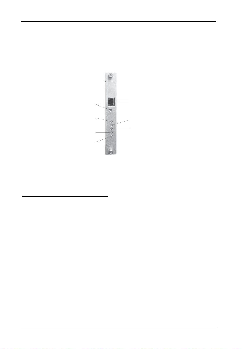
LED Indicator and User Interface Panel
Each InfoStation provides the user with a visual indication of chassis environmental and
configuration statuses, in addition to providing an RS-232 connection for system environmental
monitoring, configuration, and control (Figure 4).
RS-232
Reset
Serial Port
Override
Fault
Power
Mute
Warning
Figure 4: UI Module
LED Indicator/UI Panel Components
RS-232 - RS-232 serial connection used for InfoStation external monitoring and
Serial Port configuration
Reset Switch - Resets InfoStation User Interface Module (will not reset SCSI bus)
Override - ON = Warning condition commands are overridden
(Amber)
NOTE: Factory default is OFF (recommended).
Mute - ON = Audible alarm is disabled
(Amber)
Fault - ON = One or more fault conditions
(Red)
Warning - ON = One or more warning conditions
(Amber)
Power - ON = Power to the chassis is ON
(Green)
StorCase Technology, Inc. InfoStation 12-Bay RAID User's Guide - Rev. D00
Page 22
User Interface 9
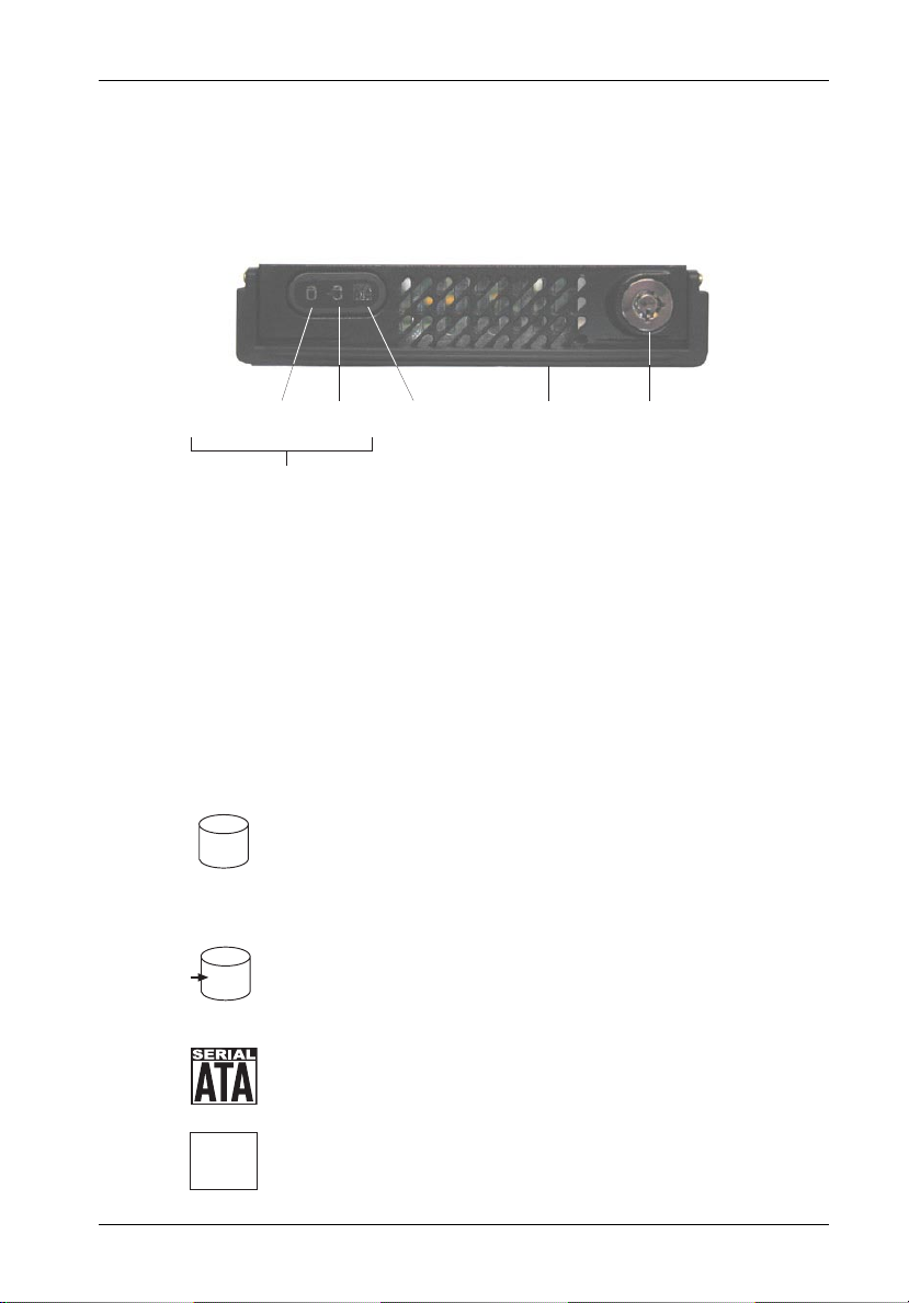
Drive Carrier Interface Panel
Each InfoStation drive carrier provides a User interface for individual carrier operation.
Drive Ready
(or Drive Fault)
LEDs
Drive
Activity
Serial ATA
Logo
Carrier
handle
Figure 5: InfoStation Drive Carrier Interface
The Drive Carrier Interface consists of the following indicators:
Table 1: Drive Carrier Interface Components
Drive Ready/
Drive Fault LED
Drive Activity LED
BLUE glow indicates that drive is inserted
and ready for access.
RED glow indicates drive failure.
AMBER glow indicates drive is being
accessed.
Key
Lock
Serial ATA logo indicates drive carrier is
for Serial ATA drives.
NO logo indicates drive carrier is for
Parallel ATA drives.
InfoStation 12-Bay RAID User's Guide - Rev. D00 StorCase Technology, Inc.
Page 23

10 User Interface
Inserting a Drive Carrier (with Drive Installed)
NOTES: A new drive can be inserted into an empty bay at anytime. However, the drive
1. Simply insert the drive carrier into the empty bay.
2. Drive is ready to be accessed when the Drive Ready LED glows BLUE.
will not be ready for access until the following procedure is followed.
The key lock is only to prevent unauthorized removal or installation of the drive
carrier. Locking the key lock is not required for drive carrier operation.
Removing a Drive Carrier (with Drive Installed)
CAUTION: Proper procedure must be followed when removing a disk drive from the drive
NOTE: Refer to the InfoStation Installation Guide for detailed information on inserting/
1. Verify that the Drive Activity LED is OFF before removing drive.
2. Unlock the key lock (if locked) and remove the drive carrier by pulling on carrier handle.
bay. It is the responsibility of the operator to ensure that the host does not
access the drive while attempting to remove the disk drive, and to follow the
procedure outlined below. Failure to do so may result in loss of data and/or
damage to the drive itself!
removing drives from the InfoStation chassis.
Configuring Device and Chassis Settings
NOTE: Refer to the InfoMon User's Guide for further information.
If necessary, use InfoMon to change any factory default device or chassis settings. Please
refer to the InfoMon User's Guide for further information.
StorCase Technology, Inc. InfoStation 12-Bay RAID User's Guide - Rev. D00
Page 24
SCSI Channel and FC Configurations 11
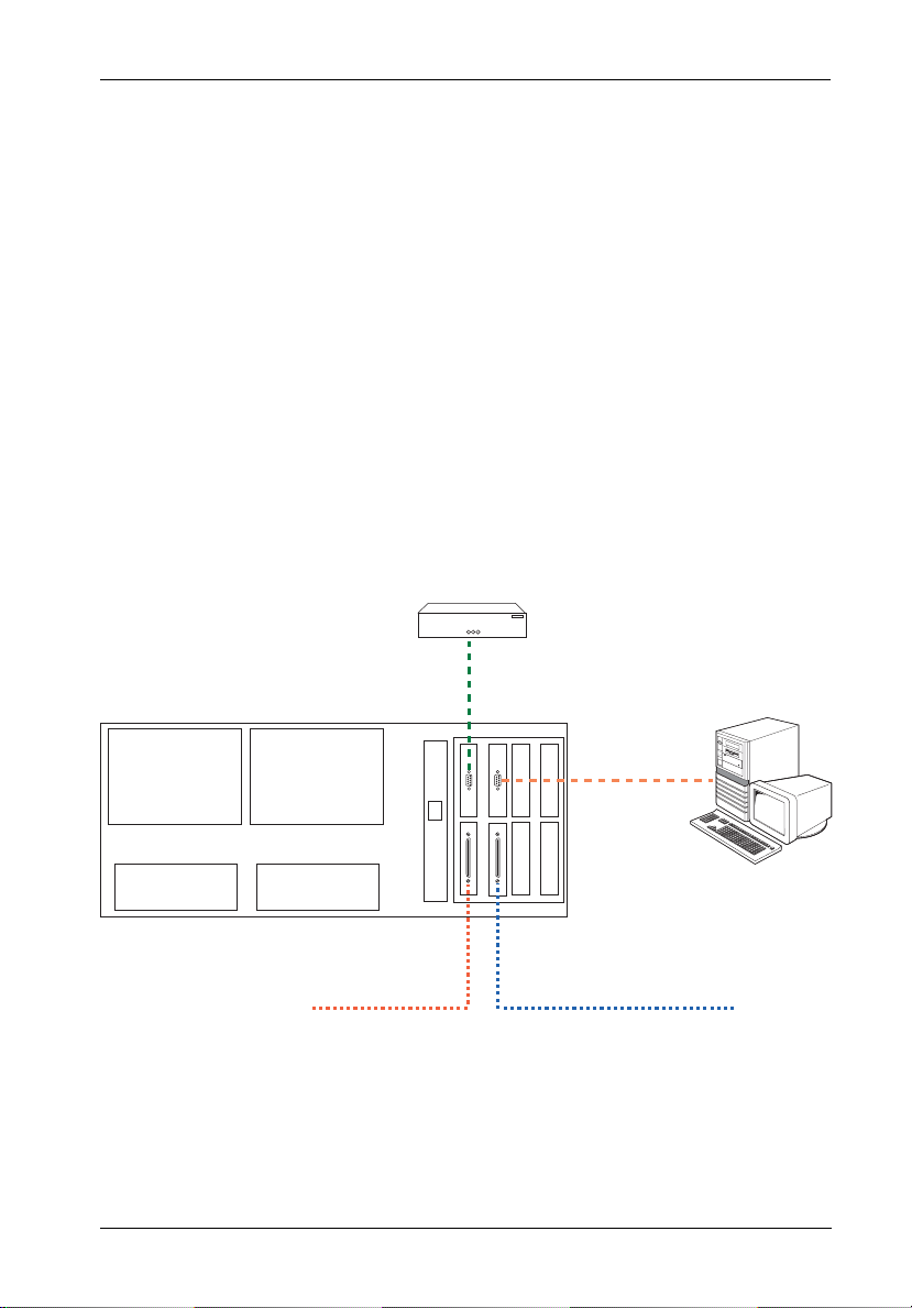
TYPICAL SCSI CHANNEL CONFIGURATION
(For SCSI-to-SATA version only)
CAUTION: VHDCI connectors are easily damaged by improper handling. Visually inspect
NOTES: The configuration and use of the InfoStation RAID Controller requires a certain
each connector for bent contacts and carefully align prior to insertion.
level of expertise and experience on the part of the user/integrator. Since there
are many configuration options and variables (ie. host platforms, applications,
etc.), only general guidelines will be discussed in this User's Guide.
For daisy-chaining applications, total device-to-host cable length should not
exceed 12m (approx. 39ft) per SCSI specifications.
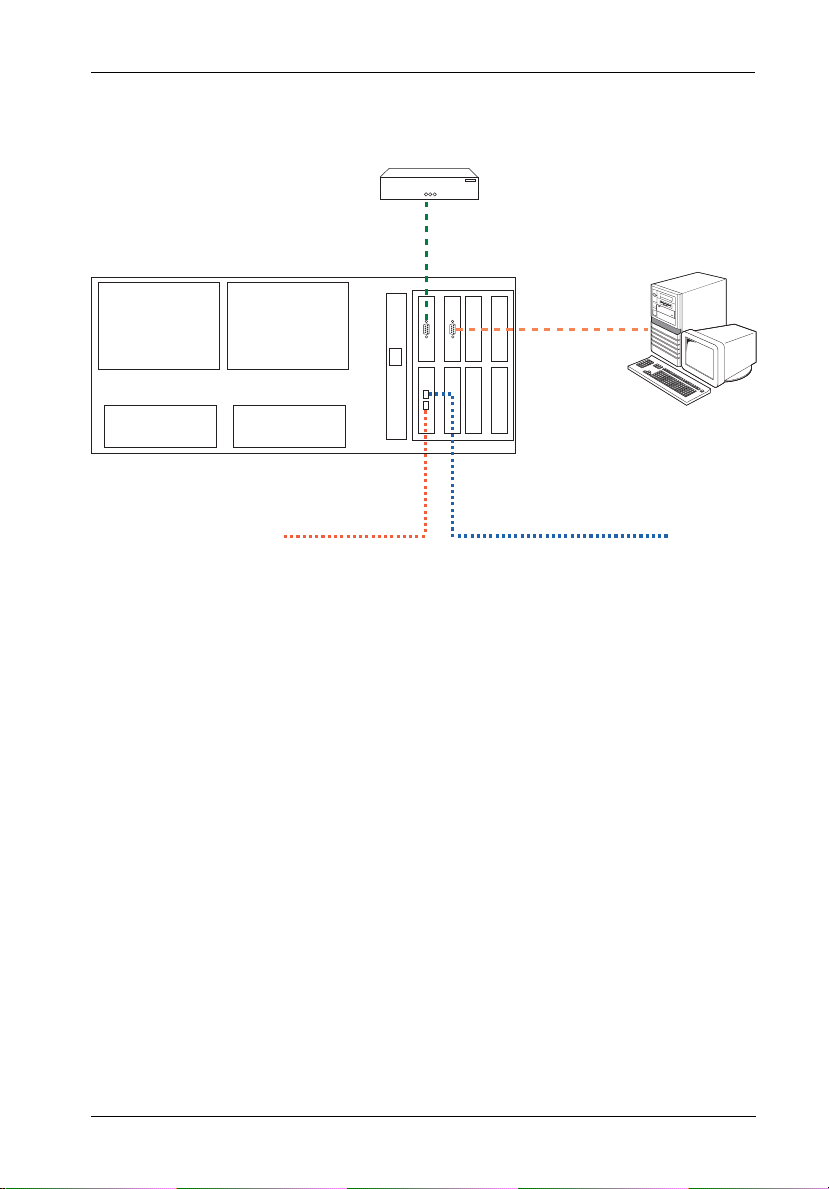
External
Modem
VT-100/ANSI
Terminal
To SCSI
Host 1
Figure 6: Typical Dual SCSI Host Connection to InfoStation
InfoStation 12-Bay RAID User's Guide - Rev. D00 StorCase Technology, Inc.
To SCSI
Host 0
Page 25
12 SCSI Channel and FC Configurations
TYPICAL FIBRE CHANNEL CONFIGURATION
(For FC-to-SATA version only)
CAUTION: DO NOT bend the LC (optical) cable beyond the cable's minimum bend radius,
data transmission degradation may occur. Follow cable manufacturer's
guidelines for bend radius limitation.
WARNING: DO NOT look directly into the open end of an active LC (optical) cable or optical
SFP module (with plugs removed)! Serious eye damage can occur from direct
exposure to the infrared light!
NOTES: The configuration and use of the InfoStation RAID Controller requires a certain
level of expertise and experience on the part of the user/integrator. Since there
are many configuration options and variables (ie. host platforms, applications,
etc.), only general guidelines will be discussed in thisUser's Guide.
LC (optical) SFP Modules support both 2Gbps and 1Gbps operation.
Status LED
Loop BLoop A
ST
ACT
FC Ports
ACT
ST
Activity LED
Figure 7: FC Ports and LEDs
LEDs
Status - ON = Steady glow during power up indicates RAID controller initialization
(will turn OFF once initialization is complete and if SFP is not connected to Host). LED will remain ON if SFP is connected to Host.
Activity - ON = Steady glow indicates activity
(Blue)
StorCase Technology, Inc. InfoStation 12-Bay RAID User's Guide - Rev. D00
Page 26
SCSI Channel and FC Configurations 13
External
Modem
VT-100/ANSI
Terminal
FC-AL #1FC-AL #2
To FC
Host 1
To FC
Host 0
Figure 8: Typical Dual FC Loops Connection to InfoStation
InfoStation 12-Bay RAID User's Guide - Rev. D00 StorCase Technology, Inc.
Page 27

14 RAID Controller Configuration
RAID CONTROLLER CONFIGURATION
NOTES: The configuration and use of the InfoStation RAID Controller requires a certain
level of expertise and experience on the part of the user/integrator. Since there
are many configuration options and variables (i.e.. host platforms, applications,
etc.), only general guidelines will be discussed in this User's Guide.
Also refer to the disk manufacturer's documentation for specific information
regarding the disks.
RAID Management Connection
NOTES: Microsoft® Windows® 3.x and Windows® NT™ 3.5x include a program called
Terminal which does not support ANSI color. If using either O/S, select VT-100
for terminal emulation or use a third-party software program such as Procomm
for Windows.
Microsoft® Windows® 95/98/NT/2000 includes a program called HyperTerminal
that supports ANSI color.
Macintosh O/S includes a program called ZTerm for terminal emulation.
The Data Master Storage Manager GUI is included on the StorCase Resource
Kit CD (provided with each InfoStation). The latest version can also be downloaded from the StorCase web site at: http://www.storcase.com/support/
datamaster.asp
Refer to the Data Master User's Guide for further information.
Both the Monitor Utility (HyperTerminal) and Data Master GUI are implemented with a VT-100
or ANSI terminal connected through the DB9 port on the rear of the InfoStation chassis (Figure 9).
StorCase Technology, Inc. InfoStation 12-Bay RAID User's Guide - Rev. D00
Page 28
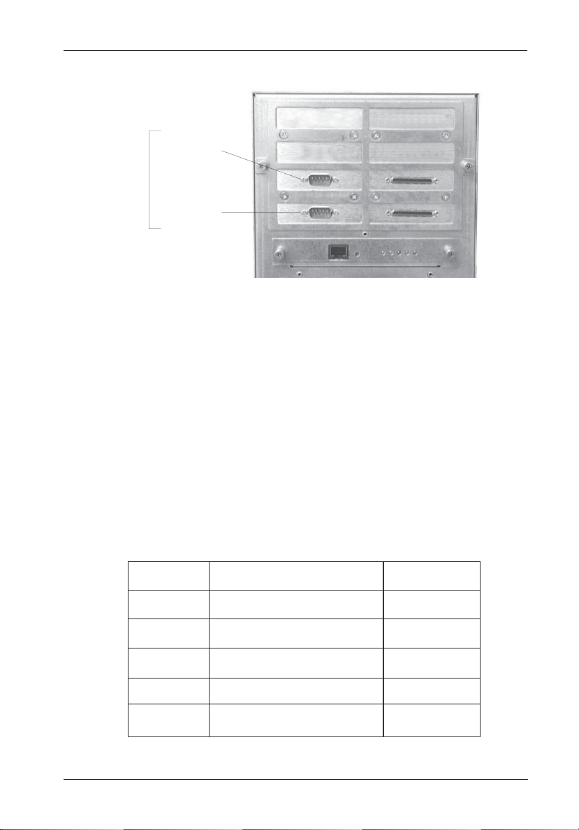
RAID Controller Configuration 15
Connect to
VT-100/ANSI
Terminal or
DataMaster
DB9
Connectors
Connect to
External
Modem
Figure 9: DB9 Port Location
(SCSI-to-SATA version shown)
Set the communications parameters (Table 2):
NOTE: The same parameters apply to both HyperTerminal and Data Master GUI.
Table 2: Communications Parameters
Setting
Baud Rate
Stop Bits
Data Bits
Parity
Flow Control
2400, 4800, 9600, 14400, 19200,
28800, 38400, 57600, 115200
Values
1, 2
7, 8
None, Odd, Even
Xon/Xoff, Hardware, None
Default Value
115200
1
8
None
None
InfoStation 12-Bay RAID User's Guide - Rev. D00 StorCase Technology, Inc.
Page 29

16 RAID Controller Configuration
Configuring the RAID Controller
There are two aspects to configuring the RAID controller:
• Configuration of the RAID system and communication parameters
• Setting up and configuration of arrays within the RAID system
Users are advised to configure the system first, then the arrays.
The following sections provide instructions on how to setup a RAID configuration for the first
time.
Choose one of the three following methods:
RAID Configuration via Data Master GUI Page
• Data Master Connection (Read FIRST before proceeding to RAID Setup) 17
• Quick RAID Setup (One array using all disks installed) 22
• Customized RAID Setup (Multiple arrays & custom number of disks in an array) 24
• Partitions 26
• LUN Mapping 32
• Deleting an Array 35
RAID Configuration via Monitor Utility (HyperTerminal) Page
• HyperTerminal Connection (Read FIRST before proceeding to RAID Setup) 36
• Quick RAID Setup (One array using all disks installed) 39
• Customized RAID Setup (Multiple arrays & custom number of disks in an array) 40
• Partitions 42
• LUN Mapping 46
• Deleting an Array 49
RAID Configuration via InfoStation RAID Control Panel Page
• RAID Control Panel (Read FIRST before proceeding to RAID Setup) 50
• Quick RAID Setup (One array using all disks installed) 55
• Customized RAID Setup (Multiple arrays & custom number of disks in an array) 56
• Partitions 58
• LUN Mapping 60
• Deleting an Array 61
StorCase Technology, Inc. InfoStation 12-Bay RAID User's Guide - Rev. D00
Page 30
RAID Controller Configuration 17
RAID Configuration via Data Master GUI
NOTES: The Data Master Storage Manager GUI is included on the StorCase Resource
Data Master Storage Manager GUI may be used to configure the InfoStation RAID controller.
Data Master makes it very easy to manage and monitor the StorCase InfoStation RAID system. The system can be managed and monitored from a remote location using the Internet
or Intranet. Also, multiple systems can be managed and monitored from a single screen (with
the Multiple Version).
Kit CD (provided with each InfoStation).
The latest version can also be downloaded from the StorCase web site at:
http://www.storcase.com/support/datamaster.asp
Refer to the Data Master User's Guide for further information.
Data Master Connection
1. Install and insert all drives to be used in the array, and power up the InfoStation by
turning on both power supply modules simultaneously.
2. Connect the COM1 port to the InfoStation RS-232 port using the provided serial cable.
3. Install Data Master onto the workstation connected to the InfoStation
(www.storcase.com/support/datamaster.asp).
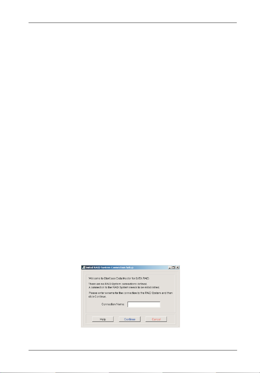
4. If you are opening Data Master for the first time, you will be prompted to enter the
name of your connection (Figure 10A). Enter the desired name in the "Connection
Name" field.
Confirm that all settings are correct and click Continue.
Figure 10A: Connection Name Setup Screen
InfoStation 12-Bay RAID User's Guide - Rev. D00 StorCase Technology, Inc.
Page 31

18 RAID Controller Configuration
If this not the first time opening Data Master and there is already a connection to an
InfoStation, the following screen should appear (Figure 10B).
(If there is already a connection to an InfoStation)
Confirm that all settings are correct and click Update.
If successful, Data Master will open with InfoStation connection present. Skip
Steps 5-10 and proceed to sections "Quick Setup" or "Customized Setup" on
pages 23-29 of this User's Guide.
5. Select the location of the InfoStation RAID system (Figure 10C).
Check “Local” connection if RAID system is connected via RS-232.
Check “Remote” connection if RAID system is connected via TCP/IP (refer to the
Data Master User’s Guide for further information).
Confirm that all settings are correct and click Continue.
StorCase Technology, Inc. InfoStation 12-Bay RAID User's Guide - Rev. D00
Figure 10B: Connection Screen
Page 32

RAID Controller Configuration 19
Figure 10C: Location Type Setup Screen
6. Select the connection type from the "Serial Port" dropdown menu (Figure 10D).
If using a “Local” connection (via RS-232), Serial Port should be set to COM1.
For “Remote” connection (via TCP/IP), refer to the Data Master User’s Guide for
further information.
Confirm that all settings are correct and click Continue.
Figure 10D: Serial Port Setup Screen
InfoStation 12-Bay RAID User's Guide - Rev. D00 StorCase Technology, Inc.
Page 33
20 RAID Controller Configuration
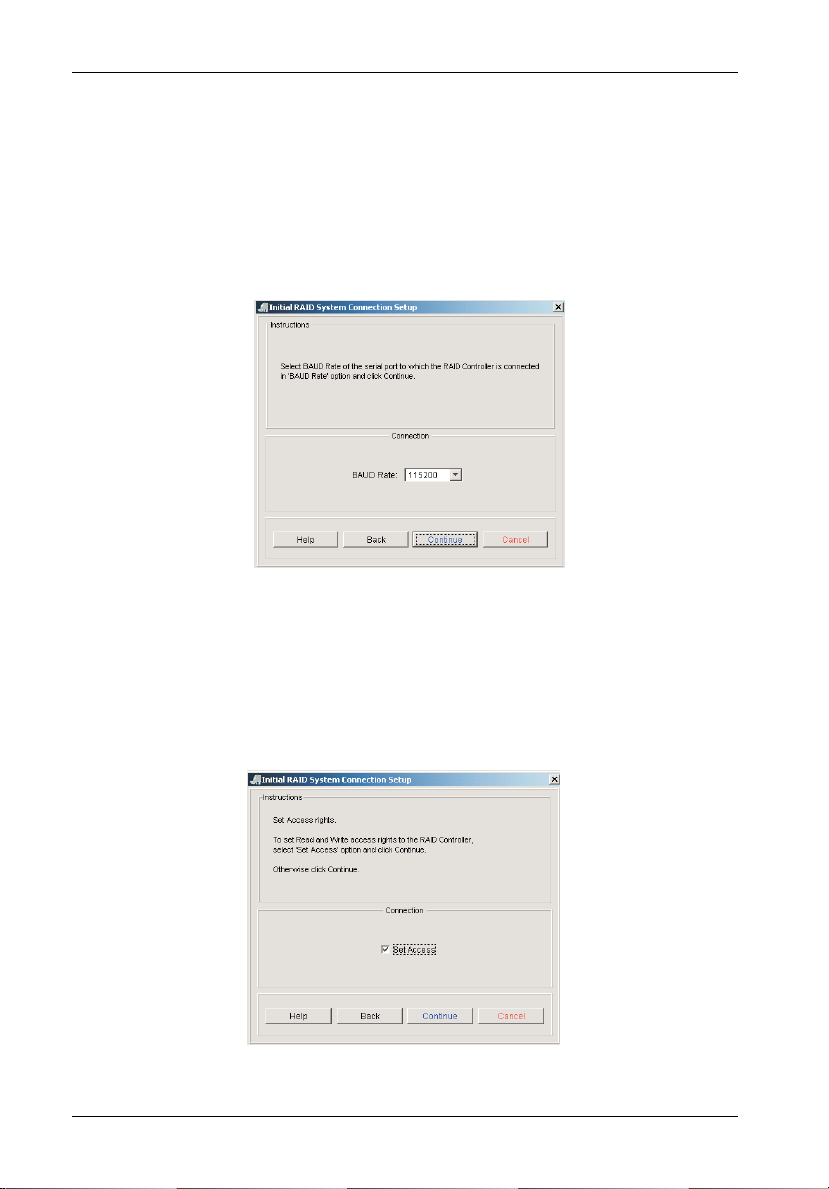
7. Select the Baud Rate from the "Baud Rate" dropdown menu (Figure 10E).
If using a “Local” connection (via RS-232), Baud Rate should be set to 115200.
For “Remote” connection (via TCP/IP), refer to the Data Master User’s Guide for
further information.
Confirm that all settings are correct and click Continue.
Figure 10E: Baud Rate Setup Screen
8. To set access rights, check the Set Access box (Figure 10F).
Confirm that all settings are correct and click Continue.
Figure 10F: Set Access Screen
StorCase Technology, Inc. InfoStation 12-Bay RAID User's Guide - Rev. D00
Page 34
RAID Controller Configuration 21
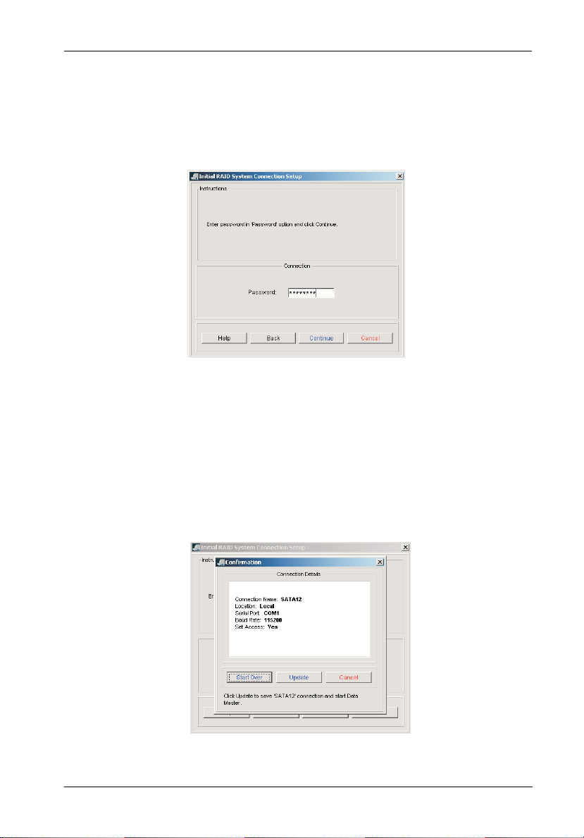
9. Enter password (default password = 00000000) in the "Password" field (Figure
10G).
Confirm that all settings are correct and click Continue.
Figure 10G: Password Screen
10. Confirm that all settings are correct and click Update (Figure 10H).
If successful, Data Master will open with InfoStation connection present.
If a change is necessary, click Start Over instead.
Figure 10H: Confirmation Screen
InfoStation 12-Bay RAID User's Guide - Rev. D00 StorCase Technology, Inc.
Page 35
22 RAID Controller Configuration
QUICK RAID SETUP
(One array using all disks installed)
1. Remove any disks unintended for the array (any disks intended for use as spares
should be physically removed prior to creating the array).
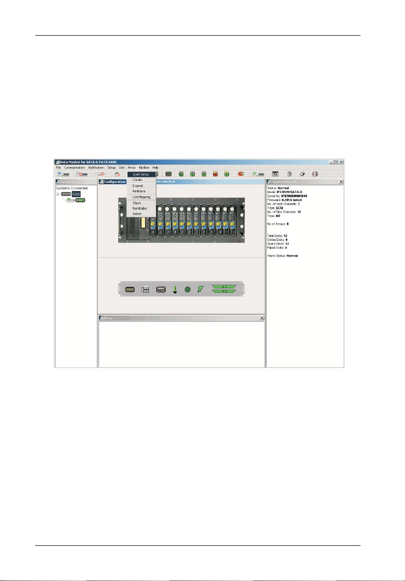
2. To create an array, select the Quick Setup option from the Array dropdown
menu (Figure 11).
Figure 11: Data Master Quick Setup Option
3. Select the desired RAID level.
4. Select the desired stripe size (default = 128MB).
5. Select the desired number of partitions.
NOTES: When using the Quick Setup option, the array will be created on
StorCase Technology, Inc. InfoStation 12-Bay RAID User's Guide - Rev. D00
ALL disks within the InfoStation (any disks intended for use as
spares should be physically removed prior to creating the array).
OS limitation is 2.0 TB maximum. However, multiple arrays or partitions can be created to achieve over 2.0 TB capacity (e.g. one
array/partition with 2.0 TB, the other array/partition with 1.0 TB, or
a combination thereof).
Page 36

RAID Controller Configuration 23
Confirm that all settings are correct and click the Update button located on the
RAID Creation screen (Figure 12).
Any disks not included in the array will automatically be added as spares.
Figure 12: Data Master RAID Creation Screen
6. After the array is created, insert any disks for use as spares.
7. Once setup is complete:
• If multiple partitions are required, proceed to section "Partitions" on page 26 of
this User's Guide.
• If no additional partitions are required, proceed to section "LUN Mapping" on
page 32 of this User's Guide.
InfoStation 12-Bay RAID User's Guide - Rev. D00 StorCase Technology, Inc.
Page 37

24 RAID Controller Configuration
CUSTOMIZED RAID SETUP
(Multiple arrays and custom number of disks in an array)
NOTE: Please familiarize yourself with section "Data Master Connection " on page
1. To create an array, select the Create option from the Array dropdown menu
17 before proceeding with customized RAID setup.
(Figure 13).
Figure 13: Data Master Create Array Option
The following screen (Figure 14) will appear.
StorCase Technology, Inc. InfoStation 12-Bay RAID User's Guide - Rev. D00
Page 38

RAID Controller Configuration 25
Figure 14: Data Master Create Array Screen
(Example shown, actual screen may vary)
2. Select the desired Array number in the "Select Array" section.
3. Select the desired RAID level in the "Select RAID Level" section.
4. Select the desired stripe size in the "Stripe Size" field.
5. Select either Random or Sequential in the "Select Performance" section.
6. If any partition in any of the arrays is over 2TB capacity:
a. Select Enable in the "Larger Than 2TB" section.
b. Select the desired sector size in the "Sector Size" section. Partition sector size
depends on the OS.
7. Select the quantity of disks for creating the Array in the "Number of Disk Drives" field.
Selected disks will display in both the "List" and "Physical View" sections.
InfoStation 12-Bay RAID User's Guide - Rev. D00 StorCase Technology, Inc.
Page 39

26 RAID Controller Configuration
8. Select the desired quantity of partitions in the "Number of Partitions" field. Available
partitions depend on the InfoStation model.
The size of each partition is shown in the "Size (GB)" field (size of all partitions are
equal). If another size is desired, enter the desired GB value in the "Size (GB)" field.
9. Select a LUN for the Primary Host Channel in the "Primary Host Channel LUN" dropdown field.
10. Select a LUN for the Secondary Host Channel in the "Secondary Host Channel LUN"
dropdown field.
11. Confirm that all settings are correct and click Create to save changes.
12. Once setup is complete:
• If multiple partitions are required, proceed to section "Setting Up Multiple Part-
itions" on page 27 of this User's Guide.
• If no additional partitions are required, proceed to section "LUN Mapping" on
page 32 of this User's Guide.
Partitions
NOTE: Please familiarize yourself with the following information before proceeding
Partitions Greater than 2TB
If creating a RAID array larger than 2TB in total capacity, two (2) partitions will automatically
be created (Figures 18A & 18B).
• Partition 1 will be approximately 2TB.
• Partition 2 will be the remaining capacity beyond 2TB (unless otherwise specified).
• If equal partitions are desired, change Partition 2 to capacity = 0GB. Once Partition 2
You are now ready to proceed to section "Setting Up Multiple Partitions" on the next page.
StorCase Technology, Inc. InfoStation 12-Bay RAID User's Guide - Rev. D00
to section "Setting Up Multiple Partitions" on page 27.
capacity is changed, change Partition 1 to desired capacity.
Page 40
RAID Controller Configuration 27
SETTING UP MULTIPLE PARTITIONS
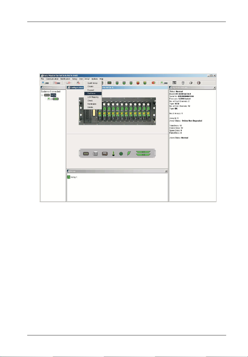
1. To create an array, select the Partitions option from the Array dropdown menu
(Figure 15).
Figure 15: Data Master Partitions Option
2. Unlock default partitions by un-checking boxes located to the left of the partition list
(highlighted in Figure 16).
3. Choose desired number of partitions in the Number of Partitions drop down menu
at the top of the partition configuration page (Figure 15).
All partitions will be divided into equal capacities.
InfoStation 12-Bay RAID User's Guide - Rev. D00 StorCase Technology, Inc.
Page 41

28 RAID Controller Configuration
Figure 16: Data Master Create Partitions Screen
4. If unequal capacities are desired, enter the desired partition sizes into the Reconfigure Size (GB) field for each partition (highlighted in Figure 17).
StorCase Technology, Inc. InfoStation 12-Bay RAID User's Guide - Rev. D00
Page 42

RAID Controller Configuration 29
Figure 17: Data Master Reconfigure Partitions Option
5. Confirm that all settings are correct and click Reconfigure Partitions (Figure 17).
6. Once partitions are created, proceed to section "LUN Mapping" on page 32 of this
User's Guide.
InfoStation 12-Bay RAID User's Guide - Rev. D00 StorCase Technology, Inc.
Page 43

30 RAID Controller Configuration
Example:
RAID 0 being created with approximately 2.2TB total capacity.
Figure 18A: Example of a RAID 0 Creation with 2.2TB Total Capacity
StorCase Technology, Inc. InfoStation 12-Bay RAID User's Guide - Rev. D00
Page 44

RAID Controller Configuration 31
Figure 18B: Example of a RAID 0 Creation with 2.2TB Total Capacity
You will notice that by default, two partitions were created (Figure 18B).
P1 = 2048GB
P2 = 182GB
InfoStation 12-Bay RAID User's Guide - Rev. D00 StorCase Technology, Inc.
Page 45

32 RAID Controller Configuration
LUN Mapping
1. After the array and Partitions have been created, each partition needs to be assigned a LUN and mapped to the appropriate SCSI Channel.
2. Select the LUN Mapping option from the Array dropdown menu (Figure 19).
Figure 19: Data Master LUN Mapping Option
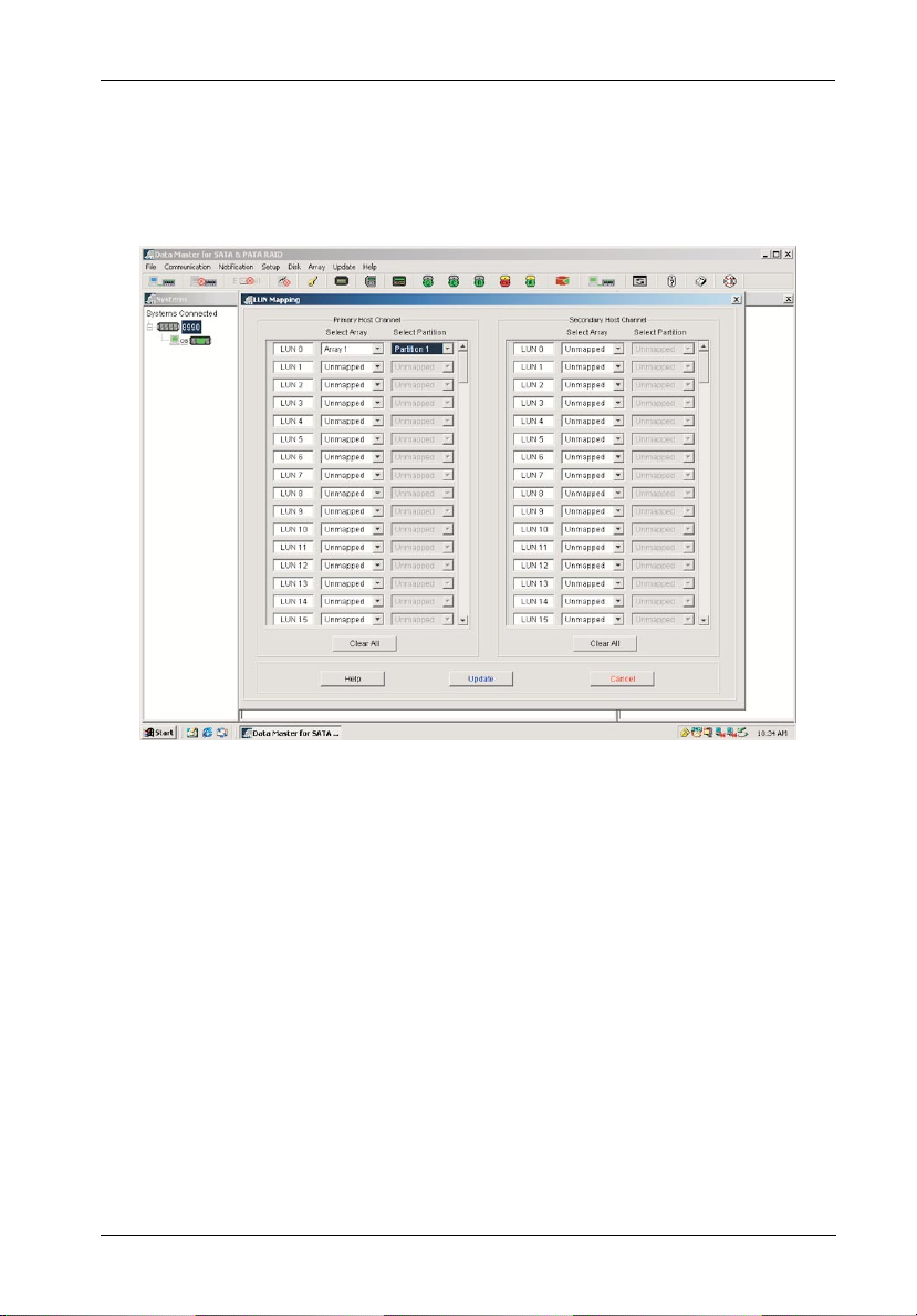
3. Starting With LUN 0, assign one LUN to each partition of each array.
Select the array(s) and partition(s) in the Select Array and Select Partition
fields in the LUN Mapping screen (Figures 20A or 20B).
4. Confirm that all settings are correct and click Update (Figures 20A & 20B).
StorCase Technology, Inc. InfoStation 12-Bay RAID User's Guide - Rev. D00
Page 46
RAID Controller Configuration 33
Example:
One Array and one Partition mapped to the Primary SCSI channel only.
Figure 20A: Example of One Array and One Partition
InfoStation 12-Bay RAID User's Guide - Rev. D00 StorCase Technology, Inc.
Mapped to Primary SCSI Channel
Page 47

34 RAID Controller Configuration
Example:
Two Arrays and two Partitions, each mapped to both Primary and Secondary SCSI channels.
Figure 20B: Example of Two Arrays and Two Partitions
Mapped to both Primary and Secondary SCSI Channels
StorCase Technology, Inc. InfoStation 12-Bay RAID User's Guide - Rev. D00
Page 48

RAID Controller Configuration 35
Deleting an Array
1. Select the Delete option from the Array dropdown menu (Figure 19).
2. Select the desired array to be deleted.
3. Click Delete located at the bottom of the screen.
InfoStation 12-Bay RAID User's Guide - Rev. D00 StorCase Technology, Inc.
Page 49

36 RAID Controller Configuration
RAID Configuration via HyperTerminal
NOTES: Microsoft® Windows® 3.x and Windows® NT™ 3.5x include a program called
The Monitor Utility (HyperTerminal) may be used to configure the InfoStation RAID controller.
Terminal which does not support ANSI color. If using either O/S, select VT-100
for terminal emulation or use a third-party software program such as Procomm
for Windows.
Microsoft® Windows® 95/98/NT/2000 includes a program called HyperTerminal
that supports ANSI color.
Macintosh O/S includes a program called ZTerm for terminal emulation.
HyperTerminal Connection
To find HyperTerminal in Windows:
1. Click on Start (normally located at the bottom left of the Windows desktop)
2. Go to Programs
3. Go to Accessories
4. Go to HyperTerminal
Settings
(Figure 21A)
· Select the appropriate COM port that the StorCase serial cable is connected to on the host
(default = COM1).
· Set Bits Per Second to 115200.
· Set Data Bits to 8.
· Set Parity to None.
· Set Stop Bits to 1.
· Set Flow Control to None.
StorCase Technology, Inc. InfoStation 12-Bay RAID User's Guide - Rev. D00
Page 50

RAID Controller Configuration 37
Figure 21A: HyperTerminal Connection Screen
When blank connection page displays, press <CTRL D> twice.
HyperTerminal should now be connected to the InfoStation RAID system (Figure 21B).
Figure 21B: Monitor Utility (HyperTerminal) Screen
InfoStation 12-Bay RAID User's Guide - Rev. D00 StorCase Technology, Inc.
(Actual screen may vary)
Page 51
38 RAID Controller Configuration
Selecting Menu Options
Use the following information (Table 3) to navigate through the Monitor Utility (HyperTerminal)
menu options:
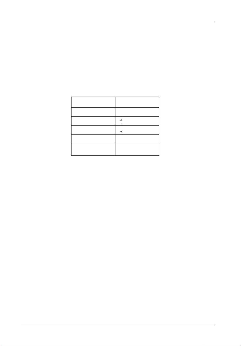
Table 3: Selecting Menu Options
Menu Options
Exit
Move Up
Move Down
Select
Switch the MENU or
OUTPUT screen
Press
Esc
or A
or Z
Enter
Tab
S_IDE05
StorCase Technology, Inc. InfoStation 12-Bay RAID User's Guide - Rev. D00
Page 52

RAID Controller Configuration 39
QUICK RAID SETUP
1. Invoke the HyperTerminal screen.
2. <TAB> to the Menu side of the screen and press <ENTER>. Enter password
(default password = 00000000).
3. Remove any disks unintended for the array (any disks intended for use as spares
should be physically removed prior to creating the array).
4. Select the Quick Setup option to create an array. Press <ENTER>.
You will be prompted to select the RAID level to create.
5. Select desired RAID level and press <ENTER>.
Select Yes and press <ENTER>.
NOTES: When using the Quick Setup option, the array will be created on
6. After the array is created, insert remaining disks for use as spares (spares are
added automatically).
7. Once setup is complete:
• If multiple partitions are required, proceed to section "Partitions" on page 42 of
this User's Guide.
• If no additional partitions are required, proceed to section "LUN Mapping" on
page 46 of this User's Guide.
ALL disks within the InfoStation (any disks unintended for the array
should be physically removed prior to creating the array).
OS limitation is 2.0 TB maximum. However , multiple arrays or partitions can be created to achieve over 2.0 TB capacity (e.g. one
array/partitions with 2.0 TB, the other array/partitions with 1.0 TB,
or a combination thereof).
InfoStation 12-Bay RAID User's Guide - Rev. D00 StorCase Technology, Inc.
Page 53

40 RAID Controller Configuration
CUSTOMIZED RAID SETUP
NOTE: Please familiarize yourself with section "HyperTerminal Connection " on page
1. Invoke the HyperTerminal screen.
2. <TAB> to the Menu side of the screen and press <ENTER>. Enter password
3. RAID configuration:
36 before proceeding with customized RAID setup.
(default password = 00000000).
a. Use keys to select RAID PARAMS. Press <ENTER>.
b. Select Array 1 and press <ENTER>.
c. Select Reconfig-RAID and press <ENTER>.
Select Yes and press <ENTER>.
d. Arrow down and select RAID Level. Press <ENTER>.
Select x (x = desired RAID level) and press <ENTER>.
e. Arrow down and select Disk Number. Press <ENTER>.
Select the number of disks to be used in the array and press <ENTER>.
NOTES: Any disks not selected for the array will automatically be added
as spares.
OS limitation is 2.0 TB maximum. However, multiple arrays or
partitions can be created to achieve over 2.0 TB capacity (e.g.
one array/partition with 2.0 TB, the other array/partition with
1.0 TB, or a combination thereof).
f . Press <ESC> twice.
StorCase Technology, Inc. InfoStation 12-Bay RAID User's Guide - Rev. D00
Page 54

RAID Controller Configuration 41
g. Arrow down and select NVRAM. Press <ENTER>.
Select Update NVRAM and press <ENTER>.
Select Yes and press <ENTER>.
Arrow down and select Restart. Press <ENTER>.
Select Yes and press <ENTER>.
4. Controller will now reboot and the RAID x array will start initialization.
NOTE: Initialization may take several hours, depending on the overall capa-
5. For additional arrays, repeat Steps 1-3.
6. Once setup is complete:
• If multiple partitions are required, proceed to section "Partitions" on page 42 of
this User's Guide.
• If no additional partitions are required, proceed to section "LUN Mapping" on
page 46 of this User's Guide.
city of the array being configured.
InfoStation 12-Bay RAID User's Guide - Rev. D00 StorCase Technology, Inc.
Page 55

42 RAID Controller Configuration
Partitions
NOTE: Please familiarize yourself with the following information before proceeding
Partitions Greater than 2TB
If creating a RAID array larger than 2TB in total capacity, two (2) partitions will be created.
1. Partition 1 will be approximately 2TB.
2. Partition 2 will be the remaining capacity beyond 2TB (unless otherwise specified).
3. If equal partitions are desired, change Slice 01 to capacity = 0GB. Once Slice 01
You are now ready to proceed to section "Viewing Default Partition Configuration".
VIEWING DEFAULT PARTITION CONFIGURATION
1. <TAB> to the Menu (left) side of the screen and press <ENTER>.
2. Enter password (default password = 00000000).
3. Select RAID Funcs. Press <ENTER>.
to section "Setting Up Multiple Partitions" on page 43.
capacity is changed, change Slice 00 to desired capacity.
4. Select Statistics. Press <ENTER>.
5. <TAB> to the Output (right) side of the screen and press <ENTER>.
6. Scroll up to the "RAID Statistics" section to view Partition values.
StorCase Technology, Inc. InfoStation 12-Bay RAID User's Guide - Rev. D00
Page 56

RAID Controller Configuration 43
SETTING UP MULTIPLE PARTITIONS
1. <TAB> to the Menu (left) side of the screen and press <ENTER>.
2. Enter password (default password = 00000000).
3. Partition configuration:
a. Use keys to select RAID PARAMS. Press <ENTER>.
b. Select Array x (x=desired array) and press <ENTER>.
c. Select Reconfig-RAID and press <ENTER>.
Select Yes and press <ENTER>.
d. Arrow down and select Slice. Press <ENTER>.
NOTE: If creating a RAID array larger than 2TB in total capacity, two (2)
e. Select Slice 0 and press <ENTER>.
Enter desired slice (partition) capacity and press <ENTER>.
If new partition/slice is smaller than default partition/slice, clear any remaining
numbers by pressing <SPACEBAR>.
NOTE: Remaining capacity will be added to Slice 1 as a second partition.
f . If three (3) or more partitions are desired, repeat Step e for last created slice.
NOTE: Changing last slice to desired capacity will result in remaining
g. Press <ESC> three times.
partitions will be created. If equal partitions are desired, change
Slice 01 to capacity = 0GB. Once Slice 01 capacity is changed,
change Slice 00 to desired capacity. Proceed to "Step e".
Confirm the partition size by reentering the number displayed in
Slice 1 and press <ENTER>.
capacity being added to an additional slice.
InfoStation 12-Bay RAID User's Guide - Rev. D00 StorCase Technology, Inc.
Page 57

44 RAID Controller Configuration
h. Arrow down and select NVRAM. Press <ENTER>.
Select Update NVRAM and press <ENTER>.
Select Yes and press <ENTER>.
Arrow down and select Restart. Press <ENTER>.
Select Yes and press <ENTER>.
Verify the newly saved slice settings by viewing default slice configuration (refer to section
"Viewing Default Partition Configuration" on page 42 of this User's Guide for further
information) .
StorCase Technology, Inc. InfoStation 12-Bay RAID User's Guide - Rev. D00
Page 58

RAID Controller Configuration 45
Example:
RAID 0 being created with approximately 2.2TB total capacity.
Figure 22: Example of a RAID 0 Creation with 2.2TB Total Capacity
You will notice that by default, two partitions were created (Figure 22).
P1 = 2097GB (located in Output, or right side of the screen)
P2 = 186GB
InfoStation 12-Bay RAID User's Guide - Rev. D00 StorCase Technology, Inc.
Page 59

46 RAID Controller Configuration
LUN Mapping
1. After the array and partitions have been created, each partition needs to be assigned a LUN and mapped to the appropriate SCSI Channel.
2. <TAB> to the Menu (left) side of the screen and press <ENTER>.
3. Enter password (default password = 00000000).
4. Select SCSI Params and press <ENTER>.
a. Select the SCSI channel your host server is connected to (Primary or Sec-
ondary SCSI) and press <ENTER>.
b. Select LUN MAP and press <ENTER>.
c. Starting with LUN 0, assign one LUN number to each partition (slice).
Select LUN number and press <ENTER>.
d. After selecting LUN number, select the array the partition is in and press
<ENTER>.
e. Select the partition (slice) you would like to assign this LUN number to and
press <ENTER> (Figure 23).
Slices always start with “00” and increase sequentially according to the
number of partitions that have been created.
StorCase Technology, Inc. InfoStation 12-Bay RAID User's Guide - Rev. D00
Page 60

RAID Controller Configuration 47
Figure 23: HyperTerminal LUN Map Option
5. Press <ESC> four times to return to the Main Menu.
6. Arrow down and select NVRAM. Press <ENTER>.
7. Select Update NVRAM and press <ENTER>.
Select Yes and press <ENTER>.
8. Select Restart and press <ENTER>.
Select Yes and press <ENTER>.
9. Controller will now reboot (LUN will be mapped upon reboot).
10. To verify LUN Mapping settings, select RAID FUNCS from the Main Menu and press
<ENTER>.
11. Select Statistics and press <ENTER>.
12. <TAB> to highlight the Output (right) side of the HyperTerminal screen. Use the
keys to scroll through Output to view either the “Primary SCSI Channel” or
“Secondary SCSI Channel” (depending where the LUNs were mapped to).
13. If the LUN settings were successfully applied, you should see the array number
and slice numbers listed in the LUN Map section (Figure 24).
InfoStation 12-Bay RAID User's Guide - Rev. D00 StorCase Technology, Inc.
Page 61

48 RAID Controller Configuration
Example:
One Array and two Slices mapped to Primary SCSI channel.
Figure 24: Example of One Array and Two Slices
Mapped to the Primary SCSI Channel
You will notice there are two sets of numbers in the LUN Map section (highlighted in Figure
24).
a. First number ( 10 11 xxxxx...) represents the Array #
b. Second number ( 10 11 xxxxx...) represents the LUN #
StorCase Technology, Inc. InfoStation 12-Bay RAID User's Guide - Rev. D00
Page 62

RAID Controller Configuration 49
Deleting an Array
1. Invoke the HyperTerminal screen.
2. <TAB> to the Menu side of the screen and press <ENTER>. Enter password
(default password = 00000000).
3. Deleting an array:
a. Use keys to select RAID PARAMS. Press <ENTER>.
b. Select array to be deleted and press <ENTER>.
c. Select Reconfig-RAID and press <ENTER>.
Select Yes and press <ENTER>.
d. Arrow down and select RAID Level. Press <ENTER>.
Arrow down and select None. Press <ENTER>.
e. Press <ESC> twice.
f . Arrow down and select NVRAM. Press <ENTER>.
Select Update NVRAM and press <ENTER>.
Select Yes and press <ENTER>.
Arrow down and select Restart. Press <ENTER>.
Select Yes and press <ENTER>.
InfoStation 12-Bay RAID User's Guide - Rev. D00 StorCase Technology, Inc.
Page 63
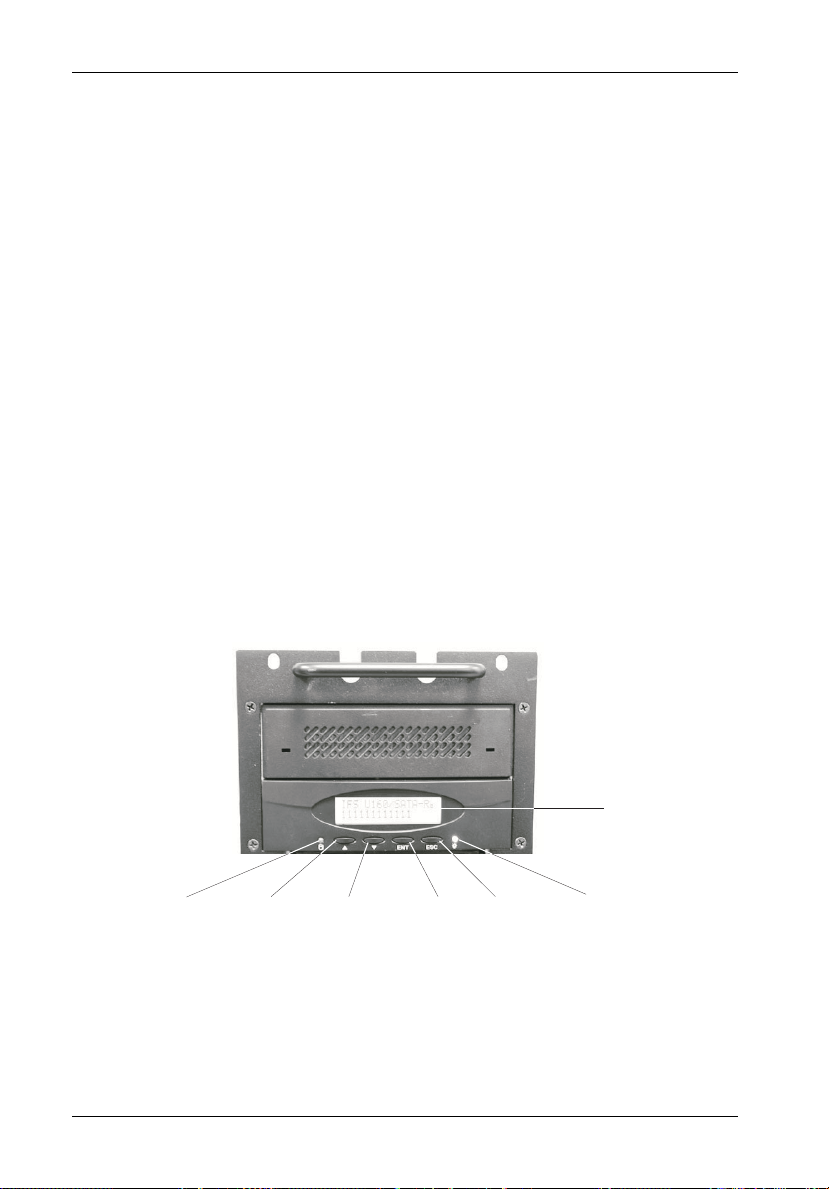
50 RAID Controller Configuration
RAID Configuration via InfoStation RAID Control Panel
The InfoStation RAID Control Panel may be used to configure the InfoStation RAID controller.
RAID Control Panel
The RAID control panel (Figure 25) allows for exploration of all configuration options. However,
the LCD screen can only display limited amounts of information at a time.
To display all information on a larger terminal screen, the RAID Controller can be accessed via
a computer serial port (female DB9-female DB9 cable provided) using either the Monitor Utility
(HyperTerminal) or Data Master GUI.
NOTE: The Monitor Utility and the front control panel cannot be used at the same time.
When one is active, the other is disabled.
LCD
Display
Activity
LED
Scroll UP
Button
Scroll DOWN
Button
Enter
Button
Escape
Button
Power
LED
Figure 25: LCD Display and Control Panel
StorCase Technology, Inc. InfoStation 12-Bay RAID User's Guide - Rev. D00
Page 64

RAID Controller Configuration 51
LEDs
Activity Indicates data is being accessed
Power Indicates power is ON
Control Panel Buttons
Use to scroll UP through the menu items
Use to scroll DOWN through the menu items
ENT Use to select a menu item, open a sub-menu, or to select a a value
ESC Use to exit a sub-menu and return to the previous menu
Table 4: LCD Display Components
Field
IFS xxxx/xATA - R
OOOOOOOOOOOS
Rx
ID:x
* IFS U320/SATA-R = InfoStation U320-to-Serial ATA RAID enclosure
IFS U320/PATA-R = InfoStation U320-to-Parallel ATA RAID enclosure
IFS FC/SATA-R = InfoStation FC-to-Serial ATA RAID enclosure
IFS FC/PATA-R = InfoStation FC-to-Parallel ATA RAID enclosure
IFS U320/SATA-J = InfoStation U320-to-Serial ATA JBOD enclosure
IFS U320/PATA-J = InfoStation U320-to-Parallel ATA JBOD enclosure
IFS FC/SATA-J = InfoStation FC-to-Serial ATA JBOD enclosure
IFS FC/PATA-J = InfoStation FC-to-Parallel ATA JBOD enclosure
Description
Model number*
Disk status. The farthest O to the left is Disk 1.
Press button to view the next page.
Symbol
RAID level (x = 0, 0+1, 1, 3, 5, 30, or 50) configuration.
SCSI ID configuration (x=0-15).
Alternating cursor indicating operational status.
Description
X
Disk is not installed.
Disk is being added.
A
Disk is Online (Single Array).
O
Array 1 Online (Multiple Array).
1
2
Array 2 Online (Multiple Array).
3
Array 3 Online (Multiple Array).
4
Array 4 Online (Multiple Array).
J
JBOD (Just a Bunch of Disks)
Disk is a spare disk.
S
R
Disk is removed.
I
Disk is being checked.
When the Enter button is pressed in Operation Mode, the RAID Controller will go into
Configuration Mode.
NOTE: Configuration Mode will automatically cancel after 3 minutes (180 seconds) of
User inactivity.
InfoStation 12-Bay RAID User's Guide - Rev. D00 StorCase Technology, Inc.
Page 65

52 RAID Controller Configuration
Operation Mode
The front panel LCD continuously displays the current status of the RAID Controller. A typical
display will look like the following:
IFS xxxx/xATA - x
OOOOOOOOOOOS
Press
Installed Memory
MBytes
Press
Array 1 Capacity
MBytes
Press
Array 8 Capacity
MBytes
Press
Firmware Revision
Press
Serial Number
Press
CPU Type
80321
Press
Array 1 Rx
Press
Array 8 Rx
Press
Disk 1
Press
Disk 12
StorCase Technology, Inc. InfoStation 12-Bay RAID User's Guide - Rev. D00
Page 66

RAID Controller Configuration 53
Mode Operation
The SCSI-to-SATA RAID Controller operates in three (3) modes:
• Self-Diagnostic Mode
• Configuration Mode
• Operation Mode
Self-Diagnostic Mode
To ensure flawless operation, the RAID Controller has a built-in self-diagnostic utility. SelfDiagnostic Mode occurs automatically upon power up, or after the RAID Controller has been
reset. During this mode, all components are tested and any potential problems are reported.
The Self-Diagnostic Mode runs three major diagnostic tests. The first diagnostic includes
testing the CPU and supporting core logic chips, the internal bus, memory, SCSI controller,
SATA controllers, and RS-232 controllers. The second diagnostic tests for the presence of
disks on each individual disk channel. It also checks the functionality of each disk found. The
final diagnostic tests the RAID functionality.
Configuration Mode
NOTE: The RAID Controller should be OFFLINE (disconnected from the host system)
Configuration Mode may be selected whenever <ENTER> is pressed during Operation Mode
or when the Monitor Utility is invoked from the remote terminal. In Configuration Mode, the user
is able to modify the settings of the RAID Controller and perform different functions to the
controller.
Entering a Password
If the password-check feature is enabled, the user will be prompted to enter a password
before proceeding (the default password is "00000000"). Refer to section "4 Password
Security" for information on how to change the default password.
The user may use the front control panel buttons to enter the password. Use the and
keys to scroll through the available characters, then press <ENTER> to select the character
and move to the next position. Once all the characters have been entered, press <ENTER>
to access the Configuration Mode.
InfoStation 12-Bay RAID User's Guide - Rev. D00 StorCase Technology, Inc.
when Configuration Mode is running.
Page 67

54 RAID Controller Configuration
The Main Menu consists of six (6) categories, as shown in Table 5.
Table 5: Main Menu Options
Main Menu
0 Quick Setup
1 RAID Params
or
(SCSI-to-SATA version only)
(FC-to-SATA version only)
2 SCSI Params
2 Fibre Params
3 RS232 Params
4 System Params
5 NVRAM
6 RAID Funcs
Main Menu Options Functions
Quick Setup Quick setup of single RAID array
RAID Params Set parameters for single or multiple arrays
SCSI Params Set SCSI parameters such as SCSI ID, speed, and LUN Mapping
(For SCSI-to-SATA only)
Fibre Params Set fibre parameters such as hard loop ID, connection mode,
(For FC-to-SATA only) data rate, LUN mapping and enabling/disabling SAN masking
RS232 Params Set parameters for modem connection and RS232 connection
to terminal
System Params Set/enable/disable password security
Configure fax and pager alert settings
NVRAM Save new configurations and restart RAID controller
RAID Funcs Initialize and check RAID 3/5 arrays
Add/remove disks to existing arrays
View system statistics
Cancel error messages
Alarm settings
Expand array
Update firmware
For detailed information regarding these Main Menu options and all their functions, refer to
section "RAID Controller Configuration Overview" on pages 62-84 of this User's Guide.
StorCase Technology, Inc. InfoStation 12-Bay RAID User's Guide - Rev. D00
Page 68

RAID Controller Configuration 55
QUICK RAID SETUP
1. Install and insert all drives to be used in the array, and power up the InfoStation by
turning on both power supply modules simultaneously. Any disks intended for use
as spares should be physically removed prior to creating the array.
2. Use the InfoStation RAID Control Panel to create an array (Figure 25).
3. Press <ENTER> once to invoke the 0 Quick Setup option. Press <ENTER> again
to select option.
Main Menu
0 Quick Setup
4. Use the keys to browse through the various RAID levels. Press <ENTER>
to select the desired RAID level.
0 Quick Setup
Level x
5. Once the desired RAID level is selected, you will be prompted to confirm your selection. Select Yes to confirm.
NOTES: When using the Quick Setup option, the array will be created on
ALL disks within the InfoStation (any disks intended for use as
spares should be physically removed prior to creating the array).
OS limitation is 2.0 TB maximum. However , multiple arrays or partitions can be created to achieve over 2.0 TB capacity (e.g. one
array/partitions with 2.0 TB, the other array/partitions with 1.0 TB,
or a combination thereof).
Level x
Yes/No
6. After the array is created, insert any disks for use as spares.
7. Once setup is complete:
• If multiple partitions are required, proceed to section "Partitions" on page 58 of
this User's Guide.
• If no additional partitions are required, proceed to section "LUN Mapping" on
page 60 of this User's Guide.
InfoStation 12-Bay RAID User's Guide - Rev. D00 StorCase Technology, Inc.
Page 69

56 RAID Controller Configuration
CUSTOMIZED RAID SETUP
NOTES: Please familiarize yourself with section "RAID Control Panel" on page 50
1. Press <ENTER> to invoke the Password screen.
2. Enter password (default password = 00000000).
3. RAID configuration:
before proceeding with customized RAID setup.
Refer to sections "1 RAID Params" and "5 NVRAM" of this User's Guide for
further information.
a. Use keys to select 1 RAID PARAMS. Press <ENTER>.
b. Select 1.1 Array 1 and press <ENTER>.
c. Select 1.1.1 Reconfig-RAID and press <ENTER>.
Select Yes and press <ENTER>.
d. Arrow down and select 1.1.2 RAID Level. Press <ENTER>.
Select x (x = desired RAID level) and press <ENTER>.
e. Arrow down and select 1.1.3 Disk Number. Press <ENTER>.
Select the number of disks to be used in the array and press <ENTER>.
NOTES: Any disks not selected for the array will automatically be added
as spares.
OS limitation is 2.0 TB maximum. However, multiple arrays or
partitions can be created to achieve over 2.0 TB capacity (e.g.
one array/partition with 2.0 TB, the other array/partition with
1.0 TB, or a combination thereof).
f . Press <ESC> twice.
StorCase Technology, Inc. InfoStation 12-Bay RAID User's Guide - Rev. D00
Page 70

RAID Controller Configuration 57
g. Arrow down and select 5 NVRAM. Press <ENTER>.
Select 5.1 Update NVRAM and press <ENTER>.
Select Yes and press <ENTER>.
Arrow down and select 5.3 Restart. Press <ENTER>.
Select Yes and press <ENTER>.
4. For additional arrays, repeat Step 3.
5. Once setup is complete:
• If multiple partitions are required, proceed to section "Partitions" on page 58 of
this User's Guide.
• If no additional partitions are required, proceed to section "LUN Mapping" on
page 60 of this User's Guide.
InfoStation 12-Bay RAID User's Guide - Rev. D00 StorCase Technology, Inc.
Page 71

58 RAID Controller Configuration
Partitions
Partitions Greater than 2TB
If creating a RAID array larger than 2TB in total capacity, two (2) partitions will be created.
1. Partition 1 will be approximately 2TB.
2. Partition 2 will be the remaining capacity beyond 2TB (unless otherwise specified).
3. If equal partitions are desired, set Partition 2 to capacity = 0GB. Once Partition 2
capacity is changed, change Partition 1 to desired capacity.
SETTING UP MULTIPLE PARTITIONS
NOTE: Refer to sections "1 RAID Params" and "5 NVRAM" of this User's Guide for further
information.
1. Press <ENTER> to invoke the Password screen.
2. Enter password (default password = 00000000).
3. Partition configuration:
a. Use keys to select 1 RAID PARAMS. Press <ENTER>.
b. Select 1.1 Array x (x=desired array) and press <ENTER>.
c. Select 1.1.1 Reconfig-RAID and press <ENTER>.
Select Yes and press <ENTER>.
d. Arrow down and select 1.1.4 Slice. Press <ENTER>.
e. Select Slice 0 and enter desired slice (partition) capacity. Press <ENTER>.
NOTE: Remaining capacity will be added to Slice 1 as a second partition.
StorCase Technology, Inc. InfoStation 12-Bay RAID User's Guide - Rev. D00
Page 72

RAID Controller Configuration 59
f . If three or more partitions are desired, repeat "Step e" for last created slice.
NOTE: Changing last slice to desired capacity will result in remaining ca-
g. Press <ESC> twice.
h. Arrow down and select 5 NVRAM. Press <ENTER>.
Select 5.1 Update NVRAM and press <ENTER>.
Select Yes and press <ENTER>.
Arrow down and select 5.3 Restart. Press <ENTER>.
Select Yes and press <ENTER>.
pacity being added to an additional slice.
InfoStation 12-Bay RAID User's Guide - Rev. D00 StorCase Technology, Inc.
Page 73

60 RAID Controller Configuration
LUN Mapping
NOTE: Refer to sections "2 SCSI Params" and "5 NVRAM" of this User's Guide for further
information.
1. After the array and partitions have been created, each partition needs to be assigned a LUN and mapped to the appropriate SCSI Channel.
2. Press <ENTER> to invoke the Password screen.
3. Enter password (default password = 00000000).
4. Select 2 SCSI Params and press <ENTER>.
a. Select the SCSI channel your host server is connected to (Primary or Sec-
ondary SCSI) and press <ENTER>.
b. Select 2.1.4 LUN MAP and press <ENTER>.
c. Starting with LUN 0, assign one LUN number to each partition (slice) of each
array.
Select LUN number and press <ENTER>.
d. After selecting LUN number, select the array the partition is in and press
<ENTER>.
e. Select the partition (slice) you would like to assign this LUN number to and
press <ENTER>.
Slices always start with “00” and increase sequentially according to the
number of partitions that have been created.
5. Press <ESC> four times to return to the Main Menu.
6. Arrow down and select 5 NVRAM. Press <ENTER>.
7. Select 5.1 Update NVRAM and press <ENTER>.
Select Yes and press <ENTER>.
8. Select 5.3 Restart and press <ENTER>.
Select Yes and press <ENTER>.
9. Controller will now reboot (LUN will be mapped upon reboot).
StorCase Technology, Inc. InfoStation 12-Bay RAID User's Guide - Rev. D00
Page 74

RAID Controller Configuration 61
Deleting an Array
NOTE: Refer to sections "1 RAID Params" and "5 NVRAM" of this User's Guide for further
information.
1. Press <ENTER> to invoke the Password screen.
2. Enter password (default password = 00000000).
3. Deleting an array:
a. Use keys to select 1 RAID PARAMS. Press <ENTER>.
b. Select array to be deleted and press <ENTER>.
c. Select 1.1.1 Reconfig-RAID and press <ENTER>.
Select Yes and press <ENTER>.
d. Arrow down and select 1.1.2 RAID Level. Press <ENTER>.
Arrow down and select None. Press <ENTER>.
e. Press <ESC> twice.
f . Arrow down and select 5 NVRAM. Press <ENTER>.
Select 5.1 Update NVRAM and press <ENTER>.
Select Yes and press <ENTER>.
Arrow down and select 5.3 Restart. Press <ENTER>.
Select Yes and press <ENTER>.
InfoStation 12-Bay RAID User's Guide - Rev. D00 StorCase Technology, Inc.
Page 75

62 RAID Controller Configuration
RAID Controller Configuration Overview
Refer to pages 62-84 for an overview of the InfoStation RAID configuration options. The
following sections contain detailed information regarding each option and all their functions.
1 RAID Params
NOTE: Configuration changes made in the RAID Params menu must be saved and the
controller restarted before changes can take effect. Refer to section "5
NVRAM" of this User's Guide for further information.
1.1.1
1 RAID Params 1.1 Array 1
1.2 Array 2*
1.3 Array 3*
1.4 Array 4*
1.5 Array 5*
1.6 Array 6*
1.7 Array 7*
1.8 Array 8*
1.9 Stripe Size
* Submenus are the same as 1.1 Array 1
Array 1
Re-conf RAID
1.1.2 RAID Level
1.1.3 Disk
Number
1.1.4 Slice
1024 / 512 / 256 /
128 / 64 / 32 / 16 / 8
No / Yes
0 / 1 / 3 / 5 / 0+1 /
30 / 50 / None
Choices dependent
on RAID level
Create slices,
set slice size
Enable / Disable1.A Write Buffer
1.B Performance
Random /
Sequential
StorCase Technology, Inc. InfoStation 12-Bay RAID User's Guide - Rev. D00
Page 76

RAID Controller Configuration 63
RAID Params Menu
1.1 Array 1
This function enables the user to configure/reconfigure Array 1.
1.1.1 Array 1 Reconfigure RAID
CAUTION: Data lost during reconfiguration cannot be recovered! StorCase strongly
NOTE: To avoid accidental erasure of existing RAID configurations, Yes must be
Select either No or Yes.
1.1.2 RAID Level
NOTE: To remove an existing RAID level, reconfigure the array with RAID level None.
Select either 0, 1, 0+1, 3, 5, 30, 50, or None.
1.1.3 Disk Number
NOTES: Verify that the required number of disks for all arrays are connected before
Select the number of disks in the RAID.
recommends the user to backup all data before reconfiguring.
selected prior to saving any new RAID configurations.
configuring an array. Refer to Table 4 for further information.
The number of disks in the array does not include the "hot spare" disk.
InfoStation 12-Bay RAID User's Guide - Rev. D00 StorCase Technology, Inc.
Page 77

64 RAID Controller Configuration
1.1.4 Slice
NOTE: A slice must be mapped to a LUN before it can be accessed. Refer to section
This function enables the user to partition the array into different slices (identified as Slice 0,
Slice 1, etc.). All RAID capacity is assigned by default to Slice 0.
Input the size of each slice in MB. All RAID capacity is assigned by default to Slice 0. If Slice
0 is reduced in size, all excess capacity will be automatically assigned to Slice 1, and so forth.
If no capacity is allocated to a slice, then that slice will not be created.
1.2 Array 2
1.3 Array 3
1.4 Array 4
1.5 Array 5
1.6 Array 6
1.7 Array 7
1.8 Array 8
This function enables the user to configure/reconfigure Arrays 2-8 (skip these sections if
single array is sufficient).
1.9 Stripe Size
NOTES: Stripe size remains constant for any RAID, for both single and multiple arrays.
"2 SCSI Params" of this User's Guide for further information.
Smaller stripe sizes provide faster access for small randomly-accessed files.
Larger stripe sizes increase transfer rates for large sequentially-accessed
files (such as video).
Set the striping block size in either 8, 16, 32, 64, 128 (default), 256, 512, or 1024 sectors.
StorCase Technology, Inc. InfoStation 12-Bay RAID User's Guide - Rev. D00
Page 78

RAID Controller Configuration 65
1.A Write Buffer
Select either Enable (default) or Disable buffer for write operations to memory.
1.B Performance
NOTES: Sequential is best for saving large amounts of data. Random is best for saving
Set writing method as either Random or Sequential.
smaller amounts of data.
Configuration changes made in the RAID Params menu must be saved and
controller restarted before changes can take effect. Refer to section "5
NVRAM" of this User's Guide for further information.
InfoStation 12-Bay RAID User's Guide - Rev. D00 StorCase Technology, Inc.
Page 79

66 RAID Controller Configuration
Array Management
The unique RAID Controller array management firmware utilizes multi-tasking real-time kernel
technology to manage the controller. Additional features are real-time load analysis, online
diagnostics, event logging and broadcasting, and device inventory management.
RAID Levels
The RAID Controller supports RAID levels 0, 0+1, 1, 3, 5, 30, and 50. Depending on the
application that will be used, each RAID level offers a difference in performance, functionality,
and fault tolerance as shown in Table 6.
Table 6: RAID Level Comparisons
RAID
Level
RAID 0
Minimum
# of Drives
2
Description
Data striping without
redundancy
Pros Cons
Highest performance
No data protection - if one drive fails,
all data is lost
RAID 1
RAID 3
RAID 5 3
RAID 10
RAID 0/1
RAID 30 6
RAID 50
2
Disk mirroring
Block-level data striping
with dedicated parity
3
drive
Block-level data striping
with distributed parity
Combination of
RAID 0 (data striping)
3
and RAID 1 (mirroring)
Data striping across two
RAID 3 arrays
Data striping across two
6
RAID 5 arrays
Very high performance and
data protection
Good write performance
Excellent performance for
large, sequential data
requests
Best cost and performance
for transaction-oriented
networks
Very high performance and
data protection
Supports multiple
simultaneous read/writes
Can also be optimized for
large, sequential requests
Highest performance and
data protection (can tolerate
multiple drive failures)
*See RAID 3
Allows one drive failure in
each array
High redundancy
*See RAID 5
Allows one drive failure in
each array
High redundancy
High redundancy costs - twice the
storage capacity is required
Poorly suited for transaction-oriented
network applications
Single parity drives do not support
multiple, simultaneous read/write
requests
Write performance is slower than
RAID 0 or RAID 1
High redundancy costs - twice the
storage is capacity required
* See RAID 3
High redundancy costs - twice the
storage is capacity required
* See RAID 5
High redundancy costs - twice the
storage is capacity required
StorCase Technology, Inc. InfoStation 12-Bay RAID User's Guide - Rev. D00
Page 80

RAID Controller Configuration 67
2 SCSI Params (For SCSI-to-SATA version only)
NOTE: Configuration changes made in the SCSI Params menu must be saved and the
RAID controller restarted before changes can take effect. Refer to section "5
NVRAM" of this User's Guide for further information.
2 SCSI Params 2.1 Primary SCSI
2.2 Secondary
SCSI*
* Submenus are the same
as 2.1 Primary SCSI
2.1.1 Set SCSI ID
2.1.2 Speed
2.1.3 Wide
2.1.4 LUN Map
2.1.5 QAS
0-14 / Multiple
Ultra320 / Ultra3 /
Ultra2 / Ultra / Fast
Enable / Disable
Match slices in
existing arrays
(up to 128 LUNs)
Enable / Disable
Enable / Disable
SCSI Params Menu
2.1 Primary SCSI
This function enables the user to configure Primary SCSI settings.
2.1.1 Set SCSI ID
Select either 0-14 or Multiple (default =0). ID7 is reserved for the SCSI card.
2.1.2 Speed
Select either Ultra320, Ultra3, Ultra2, Ultra, or Fast. Refer to Table 7 for settings.
2.1.3 Wide
Select either Enable (default) or Disable. Refer to Table 7 for settings.
InfoStation 12-Bay RAID User's Guide - Rev. D00 StorCase Technology, Inc.
Page 81

68 RAID Controller Configuration
Table 7: SCSI Setup
SCSI
Interface
SCSI-2
Wide SCSI
Ultra SCSI
Ultra Wide SCSI
Ultra2 SCSI
Ultra160 SCSI
Ultra320 SCSI
Wide Fast
Disable
Enable
Disable
Enable
Enable
Enable
Enable
Ultra
[ENT]
[ENT]
[ENT]
[ENT]
Ultra2
[ENT]
2.1.4 LUN Map
Select a LUN (0-127) and a corresponding slice to map to.
2.1.5 QAS
Select either Enable (default) or Disable.
HBA Vendor QAS Setting
Adaptec
LSI
ATT O
Enable (default)
Disable
N/A
Ultra3
[ENT]
Ultra320
[ENT]
2.2 Secondary SCSI
This function enables the user to configure Secondary SCSI settings for use in multiple host
applications. Submenus are the same as 2.1 Primary SCSI.
StorCase Technology, Inc. InfoStation 12-Bay RAID User's Guide - Rev. D00
Page 82

RAID Controller Configuration 69
2 Fibre Params (For FC-to-SATA version only)
NOTE: Configuration changes made in the Fibre Params menu must be saved and the
RAID controller restarted before changes can take effect. Refer to section "5
NVRAM" of this User's Guide for further information.
2 Fibre Params 2.1 Primary FC
2.2 Secondary
FC*
* Submenus are the same
as 2.1 Primary FC
2.3 SAN Mask
2.1.1 Enable Hard
Loop ID
2.1.2 Set Hard
Loop ID
2.1.3 Set Connection
Mode
2.1.4 Set Data Rate
2.1.5 LUN Map
2.3.1 Visible For
All Hosts
2.3.2 SAN Mapping
2.3.3 Edit WWN
Table
2.3.4 View WWN
Table
2.3.5 View SAN
Mapping
Enable / Disable
Arbitration Loop /
Point-to-Point
1Gbit / 2Gbit /
Auto-Negotiated
Match slices in
existing arrays
(up to 16 LUNs)
2.3.1.1 Port 1
2.3.1.2 Port 2
2.3.2.1 Port 1
2.3.2.2 Port 2**
** Submenus are the same
as 2.3.2.1 Port 1
2.3.3.1 - 2.3.3.8
Select Host
2.3.5.1 Port 1
2.3.5.2 Port 2
Enable / Disable
Enable / Disable
2.3.2.1.1 - 2.3.2.1.8
Select Host
Select LUN
Yes / No
2.1 Primary FC
This function enables the user to configure Primary FC settings.
2.1.1 Enable Hard Loop ID
Select either Enable or Disable (default). Enable allows the user to set the ID manually. Disable allows the controller to set the ID.
2.1.2 Set Hard Loop ID
Enter the Hard Loop ID for this controller (Hard Loop ID must be enabled).
InfoStation 12-Bay RAID User's Guide - Rev. D00 StorCase Technology, Inc.
Page 83

70 RAID Controller Configuration
2.1.3 Set Connection Mode
Select either Arbitration Loop (default) or Point-to-Point.
2.1.4 Set Data Rate
Select either 1 Gbit, 2 Gbit, or Auto-Negotiated (default).
2.1.5 LUN Map
Select a LUN (0-15) and a corresponding slice to map to.
2.2 Secondary FC
This function enables the user to configure Secondary FC settings for use in multiple host
applications. Submenus are the same as 2.1 Primary FC.
2.3 SAN Mask
SAN Masking (also known as LUN Masking) is a differentiation tool for use on fibre networks
based on the unique Worldwide Name (WWN) of each fibre card. This function enables the
user to specify which hosts are able to see the RAID controller.
2.3.1 Visible for All Hosts
This function enables the user to select whether or not the RAID controller is visible to
connected hosts.
2.3.1.1 Port 1
Select either Enable or Disable. Enable allows hosts connected to Port 1 to view the RAID
controller.
2.3.1.2 Port 2
Select either Enable or Disable. Enable allows hosts connected to Port 2 to view the RAID
controller.
StorCase Technology, Inc. InfoStation 12-Bay RAID User's Guide - Rev. D00
Page 84

RAID Controller Configuration 71
2.3.2 SAN Mapping
This function enables the user to map individual LUNs to a specified host, thereby limiting
access to certain slices to single hosts (even in dual host configurations).
2.3.2.1 Port 1
Hit Enter to proceed to 2.3.2.1.1 - 2.3.2.1.8 Select Host .
2.3.2.1.1 - 2.3.2.1.8 Select Host
Select Host 1 - Host 8, then select LUN (0-7). Select Yes or No to confirm selection.
2.3.2.2 Port 2
Hit Enter to proceed to 2.3.2.2.1 - 2.3.2.2.8 Select Host .
2.3.2.2.1 - 2.3.2.2.8 Select Host
Select Host 1 - Host 8, then select LUN (0-7). Select Yes or No to confirm selection.
2.3.3 Edit WWN Table
This function enables the user to enter individual host WWNs to the RAID controller.
2.3.3.1 - 2.3.3.8 Select Host
Select Host 1 - Host 8 and enter WWN value (default = 0000000000000000).
2.3.4 View WWN Table
This function enables the user to view a list of host WWNs in the Monitor Utility (cannot be
viewed from the control panel).
InfoStation 12-Bay RAID User's Guide - Rev. D00 StorCase Technology, Inc.
Page 85

72 RAID Controller Configuration
2.3.5 View SAN Mapping
This function enables the user to view LUN mapping to hosts in the Monitor Utility (cannot be
viewed from the control panel).
2.3.5.1 Port 1
Hit Enter to view SAN Mapping on Port 1.
2.3.5.2 Port 2
Hit Enter to view SAN Mapping on Port 2.
StorCase Technology, Inc. InfoStation 12-Bay RAID User's Guide - Rev. D00
Page 86

RAID Controller Configuration 73
3 RS232 Params
3 RS232 Params 3.1 Modem Port
3.2 Terminal Port*
* Submenus are the same
as 3.1 Modem Port
3.1.1 Baud Rate
3.1.2 Stop Bit
3.1.3 Data Bit
3.1.4 Parity Bit
2400, 4800, 9600,
14400, 28800, 38400,
57600, or 115200
1 / 2
7 / 8
None / Odd / Even
Modem Port Menu
3.1 Modem Port
This function enables the user to set the Baud Rate, Stop Bit, Data Bit, and Parity parameters
for the modem port to match those of the modem. Refer to your modem manufacturer's
documentation for further information.
3.1.1 Baud Rate
Select either 2400, 4800, 9600, 14400, 19200 , 28800, 38400, 57600, or 115200 (default).
3.1.2 Stop Bit
Select either 1 (default) or 2.
3.1.3 Data Bit
Select either 7 or 8 (default).
3.1.4 Parity
Select either None (default), Odd, or Even.
InfoStation 12-Bay RAID User's Guide - Rev. D00 StorCase Technology, Inc.
Page 87

74 RAID Controller Configuration
Terminal Port Menu
NOTES: The RAID controller's terminal port settings must match the settings of the re-
3.2 Terminal Port
This function enables the user to set the Baud Rate, Stop Bit, Data Bit, and Parity parameters
for the terminal port to match those of the host.
3.2.1 Baud Rate
Select either 2400, 4800, 9600, 14400, 19200 , 28800, 38400, 57600, or 115200 (default).
3.2.2 Stop Bit
Select either 1 (default) or 2.
3.2.3 Data Bit
Select either 7 or 8 (default).
mote terminal on the host.
Flow control should be set to "NONE" on the host terminal (refer to section
"RAID Management Connection Setup" and Table 1 for further information).
3.2.4 Parity
Select either None (default), Odd, or Even.
StorCase Technology, Inc. InfoStation 12-Bay RAID User's Guide - Rev. D00
Page 88

RAID Controller Configuration 75
4 System Params
Password Security
NOTE: Configuration changes made in the System Params menu must be saved before
changes can take effect. Refer to section "5 NVRAM" of this User's Guide for
further information.
4 System Params 4.1 Password Info
4.1.1 Password
Check
4.1.2 Set
Password
Enable/Disable
Password Info Menu
4.1 Password Info
This function enables the user to enable password security or change password.
4.1.1 Password Check
Select either Enable or Disable (default). When enabled, the user will be prompted to enter
a password when first accessing the main menu.
4.1.2 Set Password
Enter a password of up to 8 alphanumeric characters. Default password is 00000000.
InfoStation 12-Bay RAID User's Guide - Rev. D00 StorCase Technology, Inc.
Page 89

76 RAID Controller Configuration
Pager Alert Settings
NOTES: A modem must be connected to the RAID controller for the alert feature to work.
Configuration changes made in the System Params menu must be saved before
changes can take effect. Refer to section "5 NVRAM" of this User's Guide for
further information.
4 System Params 4.2 Pager Info
Pager Info Menu
4.2 Pager Info
4.2.1 Paging
4.2.2 Pager 1
No.
4.2.3 Pager 2
No.
4.2.4 Code
4.2.5 Repeat #
4.2.6 Interval
4.2.7 Page Now
Enable / Disable
4.2.2.1
Telephone
No.
4.2.2.2 Pin No.
4.2.3.1
Telephone
No.
4.2.3.2 Pin No.
4.2.4.1 Part 1
4.2.4.2 Part 2
5 / 10 / 15 / 20
5 / 10 / 15 / 20
This function enables the user to configure pager alert settings.
4.2.1 Paging
Select either Enable or Disable (default).
StorCase Technology, Inc. InfoStation 12-Bay RAID User's Guide - Rev. D00
Page 90

RAID Controller Configuration 77
4.2.2 Pager 1 No.
Enter the first pager's terminal telephone number (also called the 'port number' or 'TAP port
number') and the pager PIN (if required). Maximum 16 characters.
4.2.3 Pager 2 No.
Enter the second pager's terminal telephone number (also called the 'port number' or 'TAP port
number') and the pager PIN (if required). Maximum 16 characters.
4.2.4 Code
NOTE: Pager alert messages may be up to 16 alphanumeric characters in length.
Enter the alert message for Pager 1 under Part 1. Enter the alert message for Pager 2 under
Part 2.
4.2.5 Repeat
Select either 5 (default), 10, 15, or 20. This is the number of times the alert message will be
sent.
4.2.6 Interval
Select either 5 (default), 10, 15, or 20. This is the interval (in minutes) at which the alert message
will be repeated.
4.2.7 Page Now
This function enables the user to send a test pager alert immediately.
InfoStation 12-Bay RAID User's Guide - Rev. D00 StorCase Technology, Inc.
Page 91

78 RAID Controller Configuration
Fax Alert Settings
NOTE: Configuration changes made in the System Params menu must be saved before
changes can take effect. Refer to section "5 NVRAM" of this User's Guide for
further information.
4 System Params 4.3 Fax Info
4.3.1 Fax
4.3.2 Fax Class
4.3.3 Fax 1 No.
4.3.4 Fax 2 No.
4.3.5 Retry #
4.3.6 Fax Now
Enable / Disable
1 / 2
5 / 10 / 15 / 20
Fax Info Menu
4.3 Fax Info
This function enables the user to configure fax alert settings.
4.3.1 Fax
Select either Enable or Disable (default).
4.3.2 Fax Class
Select either 1 or 2. This defines the Fax class supported by the modem.
4.3.3 Fax 1 No.
Enter the first Fax telephone number.
StorCase Technology, Inc. InfoStation 12-Bay RAID User's Guide - Rev. D00
Page 92

RAID Controller Configuration 79
4.3.4 Fax 2 No.
Enter the second Fax telephone number.
4.3.5 Retry #
Select either 5 (default), 10, 15, or 20. This is the number of times the alert message will be
sent.
4.3.6 Fax Now
This function enables the user to send a test Fax alert immediately.
Company Info
NOTE: Configuration changes made in the System Params menu must be saved before
changes can take effect. Refer to section "5 NVRAM" of this User's Guide for
further information.
4 System Params 4.4 Company Info
4.4.1 String 1
4.4.2 String 2
Company Info Menu
4.4 Company Info
This function enables the user to configure company info on fax alerts.
4.4.1 String 1
Enter the first line of information to be used as the alert Fax header (up to 16 alphanumeric
characters maximum).
InfoStation 12-Bay RAID User's Guide - Rev. D00 StorCase Technology, Inc.
Page 93

80 RAID Controller Configuration
4.4.2 String 2
Enter the second line of information to be used as the alert Fax header (up to 16 alphanumeric
characters maximum).
Modem Settings
NOTE: Configuration changes made in the System Params menu must be saved before
changes can take effect. Refer to section "5 NVRAM" of this User's Guide for
further information.
4 System Params 4.5 Modem Init St
4.5.1 String 1
Modem Init St Menu
4.5 Modem Init St
NOTES: The default string is a generic string compatible with most modems. Refer to
the modem manufacturer's documentation for further information.
Configuration changes made in the System Params menu must be saved before
changes can take effect. Refer to section "5 NVRAM" of this User's Guide for
further information.
This function enables the user to configure the modem used for the remote notification
feature.
4.5.2 String 2
Enter the second line of information to be used as the alert Fax header (up to 16 alphanumeric
characters maximum).
StorCase Technology, Inc. InfoStation 12-Bay RAID User's Guide - Rev. D00
Page 94

RAID Controller Configuration 81
5 NVRAM
Saving Configurations
CAUTION: Any changes made in this menu will permanently erase data on disks! RAID
controller should be offline before any configuration changes are made.
NOTES: The RAID controller must be restarted for any configuration changes (in Quick
Setup, RAID Params, and SCSI Params) to take effect.
Configuration changes in RS232 Params, System Params, and RAID Funcs do
not require a restart of the RAID controller.
5 NVRAM
5.1 Update
NVRAM
5.2 Erase
NVRAM
5.3 Restart
Yes / No
Yes / No
Yes / No
NVRAM Menu
5.1 Update NVRAM
Select Yes or No (default). Select Yes to store latest configuration settings in NVRAM.
5.2 Erase NVRAM
Select Yes or No (default). Select Yes to clear contents of NVRAM and restore configuration
defaults.
5.3 Restart
Select Yes or No (default). Select Yes to restart the RAID controller.
InfoStation 12-Bay RAID User's Guide - Rev. D00 StorCase Technology, Inc.
Page 95

82 RAID Controller Configuration
6 RAID Functions
Saving Configurations
CAUTION: Initialization of an existing array will erase all data on the array!
Checking of an existing array will permanently erase on the array!
6 RAID Functions
6.1 Init Parity
6.2 Parity Check
6.3 Beeper
6.4 Stop Modem
6.5 Add Disk
6.6 Remove Disk
6.7 Statistic
6.8 Expand Array
6.9 Log Event
6.A Utility
6.B Update ROM
Select Array
Select Array
Clear / Enable /
Disable
No / Yes
Select Disk
Number
Select Disk
Number
Select Array
6.9.1 Erase
6.9.2 Statistic
6.9.3 RTC
6.A.1 Disk Self
Test
6.A.2 Disk
Scrubbing
6.A.3 Disk
Clone
6.A.4 SMART
Stop / Start
Stop / Start
Select Number of
Disks
6.9.3.1 Set RTC
6.9.3.2 Show
RTC
6.9.3.3 Stop
RTC
6.A.1.1 Short
Self Test
6.A.1.2 Extended
Self Test
6.A.1.3 Stop
DST
6.A.2.1 Overwrite
Parity
6.A.2.2 Scrub
Mode
6.A.3.1 Start Disk
Clone
6.A.3.2 Stop Disk
Clone
6.A.3.3
Replace
Source Disk
6.A.4.1 Test Disk
SMART
6.A.4.2 SMART
Mode
6.A.4.3
SMART
Check Time
6.A.4.4 Bad
Blocks
Yes / No
No/Yes
Manual Scrubbing/
Schedule Scrubbing/
View Schedule
Source Disk/Target Disk/
Start Permanent Clone/
Start Swap after Clone
Disk 1 - Disk 16
Disk 1 - Disk 16
Select Disk
Number
Disable/Enable (Alert only)/
Enable (Permanent clone)/
Enable (Start swap after
clone)
60 mins/30 mins/
15 mins/1 min
6.A.4.4.1
Statistics
6.A.4.4.2
for Clone
6.A.4.4.3
for Swap
View
Threshold
Threshold
StorCase Technology, Inc. InfoStation 12-Bay RAID User's Guide - Rev. D00
Page 96

RAID Controller Configuration 83
RAID Functions Menu
6.1 Init Parity
This function enables the user to initialize an existing RAID 3, RAID 5, RAID 30, or RAID 50 array.
Select either Array 1, 2, 3, 4, 5, 6, 7, or 8 and then either Stop (default) or Start.
6.2 Parity Check
This function enables the user to check an existing RAID 3, RAID 5, RAID 30, or RAID 50 array
for errors.
Select either Array 1, 2, 3, 4, 5, 6, 7, or 8 and then either Stop (default) or Start.
6.3 Beeper
Select either Clear, Enable (default), or Disable. Clear is used to stop a sounding beeper.
6.4 Stop Modem
Select either No (default) or Yes. Select Yes to halt the transmission of subsequent alert
pager/Fax messages once the message has been received and acknowledged.
6.5 Add Disk
NOTE: Add disk(s) to an existing configuration while the RAID controller is online.
Select disk number (1-12).
6.6 Remove Disk
NOTE: Remove disk(s) from an existing configuration while the RAID controller is on-
Select disk number (1-12). This function enables the user to shutdown a potentially faulty disk.
If a spare disk is available, it will automatically be added (default = None).
InfoStation 12-Bay RAID User's Guide - Rev. D00 StorCase Technology, Inc.
line.
Page 97

84 RAID Controller Configuration
6.7 Statistic
NOTE: This option cannot be viewed from the Control Panel (it can only be viewed from
This function enables the user to display system data. Data includes:
• Current settings saved in NVRAM
• Statistical analysis of read and write operations, plus the percentage of cache hits
6.8 Expand Array
CAUTION: Data may be lost during the expansion process! StorCase strongly recommends
NOTE: Make sure that new disk capacity is equal to or larger than the current online
Select array to be expanded (Array 1-8), then the number of disks in the new array.
To expand disk capacity:
1. Connect new disk.
2. Use Expand Array menu to select the number of disks in the array.
the Monitor Utility).
the user to backup all data before expanding.
capacity.
3. Go to the 1.1.4 Slice menu. The new capacity should appear as a new slice. If no
slices were created previously, the new capacity will appear as Slice 1.
6.9 Log Event
6.9.1 Erase
This function enables the user to erase the event log.
6.9.2 Statistic
StorCase Technology, Inc. InfoStation 12-Bay RAID User's Guide - Rev. D00
Page 98

RAID Controller Configuration 85
6.9.3 RTC
NOTE: When using the RAID controller for the first time, users will need to set the RTC
This function enables the user to adjust real-time clock settings.
6.9.3.1 Set RTC
Enter the time in MM/DD/YY W HH:MM format.
(MM = Month, DD=Day, YY=Year, W=Week, HH=Hour, MM=Minute)
6.9.3.2 Show RTC
Select to have time displayed on control panel.
6.9.3.2 Stop RTC
Select to turn off RTC.
Parameters. Setting the RTC parameters will enable the RTC function on the
controller. When an event occurs, the Log Event wil then be able to record the
event in real-time.
6.A. Utility
6.A.1 Disk Self Test (DST)
This function enables the user to detect the disk's status.
6.A.1.1-6.A.1.2 Short Self Test or Extended Self Test
Select one of the two functions to do all disks or Disk 1-16 detection.
InfoStation 12-Bay RAID User's Guide - Rev. D00 StorCase Technology, Inc.
Page 99

86 RAID Controller Configuration
6.A.1.3 Stop DST
6.A.2 Disk Scrubbing
NOTES: For disk scrubbing to start, the array must be at its optimum. There cannot be
This function enables the user to prevent unrecoverable data loss, recover bad blocks, and
fix parity errors.
Disk scrubbing provides the following advantages:
1. Disk scrubbing will not prevent normal host access. It will slow down the system's
2. Disk scrubbing can be started and processed simultaneously for multiple arrays.
6.A.2.1 Overwrite Parity
Select either No (Default) or Yes. Select Yes to overwrite parity if inconsistency is detected
during disk scrubbing.
6.A.2.2 Scrub Mode
any failed member disks or background tasks (such as adding a disk or expanding an array).
Once disk scrubbing starts, the user cannot start any other background task
and array cannot be deleted.
overall performance however.
6.A.2.2.1 Manual Scrubbing
This function enables the user to select one array or all arrays to start disk scrubbing. This
function also enables the user to stop disk scrubbing at anytime.
StorCase Technology, Inc. InfoStation 12-Bay RAID User's Guide - Rev. D00
Page 100

RAID Controller Configuration 87
6.A.2.2.2 Schedule Scrubbing
NOTES: If the array is not at its optimum, the controller will cancel disk scrubbing and
This function enables the user to schedule disk scrubbing for one array or all arrays.
If enabled, the user can then select Once, Once per week, Once per 4 weeks, Once per
8 weeks, Once per 12 weeks, Once per 16 weeks, Once per 20 weeks, or Once per
24 weeks to schedule disk scrubbing.
6.A.2.2.3 View Schedule
This function enables the user to check the disk scrubbing schedule.
6.A.3 Disk Clone
NOTES: For disk cloning to start, the array must be at its optimum. There cannot be
record this event in the event log.
If the InfoStation is not ON at the time of a scheduled scrub, disk scrubbing will
not occur and controller will record this event in the event log.
any failed member disks or background tasks (such as adding a disk or expanding an array).
Once disk scrubbing starts, the user cannot start any other background task
and array cannot be deleted.
Disk cloning, like mirroring, prevents failure of disks from data loss and unscheduled performance degradation.
Disk cloning provides the following advantages:
1. Disk cloning will not prevent normal host access. It will slow down the system's
overall performance however.
2. Disk cloning can be started and processed simultaneously for multiple arrays.
6.A.3.1 Start Disk Clone
This function enables the user to start disk cloning.
InfoStation 12-Bay RAID User's Guide - Rev. D00 StorCase Technology, Inc.
 Loading...