

Page 1

Removable
SCSI Single-Ended
Drive Enclosure
User's Guide
StorCase® Technology
Data Express
®
DE75i-S
Page 2

i
DE75i-S User's Guide - Rev. A01 StorCase Technology, Inc.
StorCaseTechnology, Inc.
17600 Newhope Street
Fountain Valley, CA 92708-9885
Phone (714) 438-1850 Fax (714) 438-1847
StorCase® Technology
Data Express
®
DE75i-S
Removable
SCSI Single-Ended
Drive Enclosure
User's Guide
Part No. D89-0000-0065 A01 December 2002
Page 3

ii
StorCase Technology, Inc. DE75i-S User's Guide - Rev. A01
LIMITED WARRANTY
STORCASE TECHNOLOGY, Incorporated (StorCase) warrants that its products will be free
from defects in material and workmanship, subject to the conditions and limitations set forth
below. StorCase will, at its option, either repair or replace any part of its product that proves
defective by reason of improper workmanship or materials. Repair parts or replacement
products will be provided by StorCase on an exchange basis, and will be either new or
reconditioned to be functionally equivalent to new.
This warranty does not cover any product damage that results from accident, abuse, misuse,
natural or personal disaster, external power surge or failure, or any unauthorized disassembly, repair or modification. StorCase will not be responsible for any software, firmware or other
customer data stored within, or interfacing with a StorCase product.
Duration of Warranty
Seven-Year Warranty: The following StorCase products are covered by this warranty for
a period of seven (7) years from the original date of purchase from StorCase or its authorized
reseller: all Data Express® removable device enclosures and all StorCase interface cables and
accessories specifically intended for use with these products. Data Silo®, Data Stacker® and
InfoStation® products are covered by this warranty for a period of seven (7) years, excepting
the RAID controller, power supply, fan and blower components, which are covered by the
three-year warranty described below.
Three-Year Warranty: The following StorCase products are covered by this warranty for
a period of three (3) years from the original date of purchase from StorCase or its authorized
reseller: all Rhino®JR external expansion chassis and all RAID controller modules. In addition,
the following components of the Data Silo®, Data Stacker®, InfoStation® products are subject
to warranty for a period of three (3) years: all power supplies, fans and blowers.
Warranty Claim Requirements
To obtain warranty service, the defective product must be returned to your local authorized
StorCase dealer or distributor, or, with prior StorCase approval, to the StorCase factory
service center.
For defective products returned directly to StorCase, a Return Material Authorization (RMA)
number must be obtained by calling StorCase Customer Service at (714) 445-3455. The RMA
number must be prominently displayed on the outside of the return package. Shipments must
be freight-prepaid and insured, and must include the product serial number, a detailed
description of the problem experienced, and proof of the original retail purchase date. Products
must be properly packaged to prevent damage in transit. Damage resulting from improper
packaging will not be covered by this warranty. The StorCase factory service center is located
at 17650 Newhope Street, Receiving Dock, Gate #4, Fountain Valley, CA 92780, U.S.A.
Page 4

iii
DE75i-S User's Guide - Rev. A01 StorCase Technology, Inc.
Free Technical Support
StorCase provides free technical support. If you experience any difficulty during the
installation or subsequent use of a StorCase product, please contact StorCases Technical
Support Department prior to servicing your system. This warranty covers only repair or
replacement of defective StorCase products, as described above. StorCase is not liable for,
and does not cover under warranty, any costs associated with servicing and/or installation
of StorCase products.
StorCase Technical Support can be reached in the U.S. at (714) 438-1858 or toll-free at (888)
435-5460 (U.S. and Canada only). StorCase European Technical Support can be reached in
the U.K. at +44 (0) 1932 738900.
Disclaimers
The foregoing is the complete warranty for the products identified above and
supersedes all other warranties and representations, whether oral or written.
StorCase expressly disclaims all warranties for the identified products, which are
not stated herein, including, to the extent permitted by applicable law, any implied
warranty of merchantability or fitness for a particular purpose. In no event will
StorCase be liable to the purchaser, or to any user of a StorCase product, for any
damages, expenses, lost revenues, lost savings, lost profits, or any other
incidental or consequential damages arising from the purchase, use or inability
to use a StorCase product, even if StorCase has been advised of the possibility
of such damages.
Copyright © 2003 StorCase Technology. All rights reserved. All registered
trademarks are the property of StorCase Technology. All other logos and trademarks
are properties of their respective companies.
Page 5
iv
StorCase Technology, Inc. DE75i-S User's Guide - Rev. A01
Declaration of Conformity
StorCase Technology, Inc.
17600 Newhope Street
Fountain Valley, CA 92708
17600 Newhope Street
Fountain Valley, CA 92708
Data Express DE75
DE75i-XXXX/XXX
EN 50081-1: 1992 Generic Emission
- EN 55022/CISPR22 Class B
EN 50082-1: 1992 Generic Immunity
- IEC 1000-4-2 ESD
- IEC 1000-4-3 Radiated Immunity
- IEC 1000-4-4 Electrical Fast Transient
EN 60950
CAN/CSA-C22.2 No. 950-95
UL 1950
EN 60950: 1988 EN 60950/A2: 1991
EN 60950/A1: 1990
FCC Part 15, Class B
AS/NZS 3548 Information Technology Equipment
1998
Company Name:
Corporate Office Address:
Manufacturing Address:
Product Name:
Model Number:
Conforms to the following standards:
EMC Directives:
(89/336/EEC)
Low Voltage Directive:
(73/23/EEC)
Safety Standards:
CSA (NRTL/C)
TUV
EMI Standards:
EMC Standards:
Year of Manufacture:
Signature:___________________
Full name: Dieter Paul
Position: President
Page 6

v
DE75i-S User's Guide - Rev. A01 StorCase Technology, Inc.
Table of Contents
INTRODUCTION ..................................................................................................................... 1
Packaging Information .................................................................................................. 1
Serial Numbers .............................................................................................................. 1
Package Contents ......................................................................................................... 2
General Description ...................................................................................................... 3
Receiving Frame Front Panel ............................................................................... 4
Receiving Frame Rear Panel ................................................................................ 6
INSTALLATION ...................................................................................................................... 7
Installing the Drive into the Carrier ............................................................................... 7
Preparation ............................................................................................................ 7
Installation ............................................................................................................. 8
Installing the Receiving Frame ................................................................................... 10
Selecting the Unit ID Number ...................................................................................... 13
Spin Down/Up Timer ................................................................................................... 15
SCSI Interface Connector .......................................................................................... 16
APPENDICES ........................................................................................................................ 17
Appendix A - Specifications/Dimensions .................................................................. 18
Appendix B - Attaching the ON/OFF Key .................................................................. 20
Appendix C - Optional Accessories .......................................................................... 21
Carrying Case ..................................................................................................... 21
Reader's Comments............................................................................................................ 23
Page 7

vi
StorCase Technology, Inc. DE75i-S User's Guide - Rev. A01
List of Figures
Figure 1: Package Contents .............................................................................................. 2
Figure 2: DE75i-S Receiving Frame and Carrier .............................................................. 3
Figure 3: Receiving Frame Front Panel ............................................................................. 4
Figure 4: Receiving Frame Unit ID Number and Activity Display ..................................... 5
Figure 5: Receiving Frame Motherboard (Rear View) ..................................................... 6
Figure 6: Drive Installation Assembly ................................................................................ 8
Figure 7: Typical SCSI ID Select Connections (2mm Drive Pins) ..................................... 9
Figure 8: Receiving Frame Motherboard Option Pins ..................................................... 10
Figure 9: Receiving Frame Mounting Holes .................................................................... 12
Figure 10: Unit ID Select Switch Location ........................................................................ 14
Figure 11: Device Spin Down/Up Timer ............................................................................ 15
Figure A-1: DE75i-S Physical Dimensions .......................................................................... 19
Figure B-1: Attaching the ON/OFF Key .............................................................................. 20
Figure C-1: Carrying Case ................................................................................................... 21
List of Tables
Table 1: Option Pin Signal Descriptions ......................................................................... 11
Table 2: SCSI Interface Connector Pin Assignments ................................................... 16
NOTICE: This User's Guide is subject to periodic updates without notice. While reasonable
efforts have been made to ensure the accuracy of this document, StorCase
Technology, Inc. assumes no liability resulting from errors or omissions in this
publication, or from the use of the information contained herein.
Please check the StorCase web site at http://www.storcase.com or contact your
StorCase representative for the latest revision of this document.
Page 8

Introduction 1
DE75i-S User's Guide - Rev. A01 StorCase Technology, Inc.
INTRODUCTION
PackagingInformation
The StorCase Technology Data Express® system is shipped in a container designed to provide
protection and prevent damage during shipment. The Data Express unit was carefully
inspected before and during the packing procedure at the factory. Bent or broken connectors,
or evidence of other damage to the Data Express should be reported to the shipper immediately.
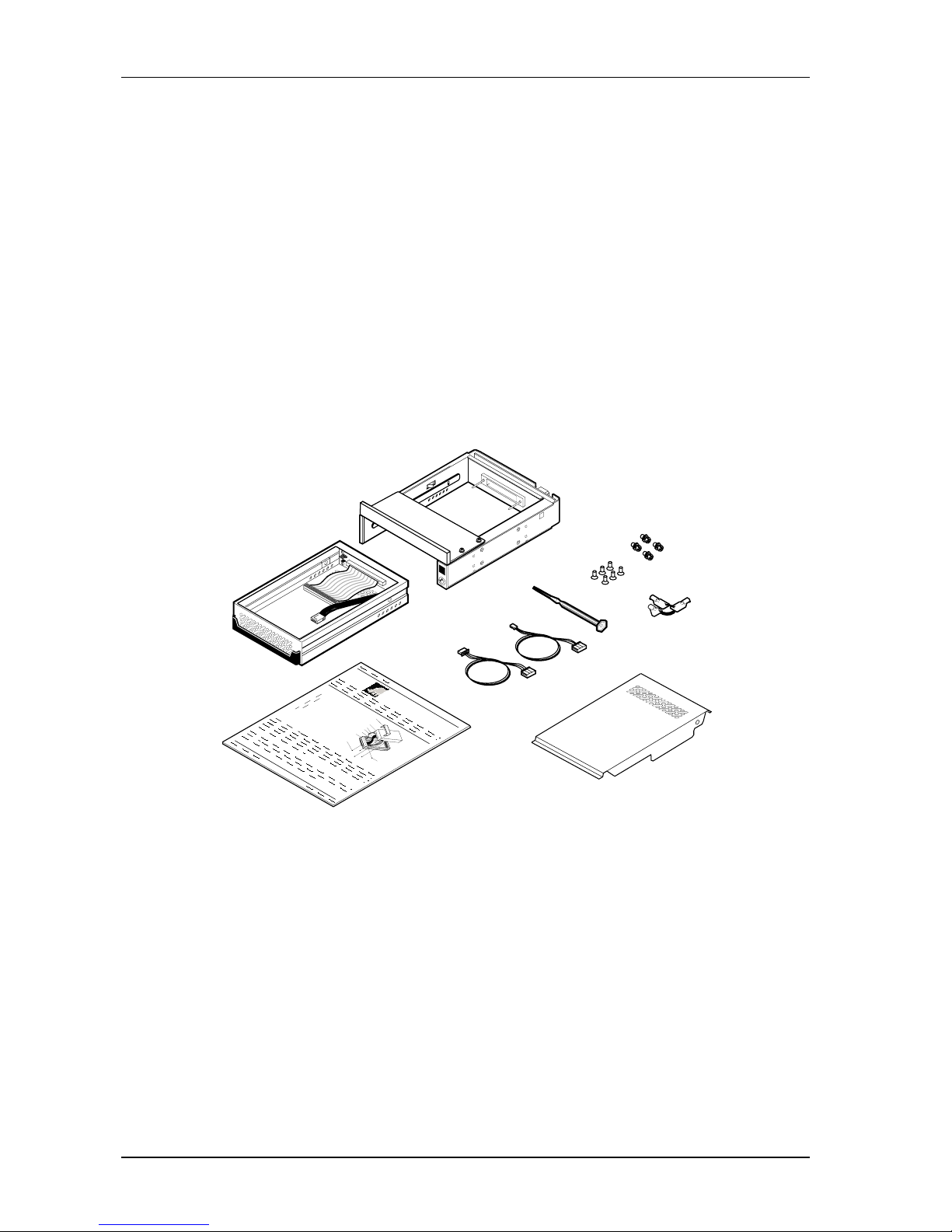
Refer to Figure 1 for the package contents.
If the wrong Data Express model has been received, please call your reseller or StorCase at
(800) 435-0642 to arrange for a Return Material Authorization (RMA). StorCase cannot accept returns which do not display an RMA number on the outside of the package. Return the
unit with all the original packing materials.
Before removing any component from its packaging, discharge any static electricity by
touching a properly grounded metal object.
Serial Numbers
Both the Data Express receiving frame and carrier are labeled with serial numbers. These
numbers must be reported to the StorCase Customer Service Representative in order to
receive a Return Material Authorization (RMA) for warranty claims. Locate the serial number
labels and record the numbers in the spaces provided below.
Receiving Frame:
Device Carrier:
Page 9
2 Introduction
StorCase Technology, Inc. DE75i-S User's Guide - Rev. A01
PackageContents
The DE75i-S product shipment should include the following items. If any item is missing or
damaged, contact your StorCase dealer for a replacement.
Figure 1: Package Contents
6. #6-32 Phillips F.H. Mounting Screws
7. Alignment Tool
8. SCSI ID Select Cable (0.1"/1.25mm)
9. SCSI ID Select Cable (0.1"/2mm)
10. Drive Cover
11. Insert Sheet
1. Drive Carrier
2. 5.25" Adapter Bracket
(shown installed)
3. Receiving Frame
4. #6-32 Phillips Machine Hd.
Screws
5. Drive Lock Keys
4
7
10
5
1
3
8
9
6
2
11
D
a
ta
E
x
p
re
s
s
D
r
i
v
e
C
a
r
r
i
e
r
D
i
s
k
D
r
i
v
e
(
N
o
t
I
n
c
l
u
d
e
d
)
P
o
w
e
r
C
a
b
l
e
I
/
O
C
a
b
l
e
D
r
i
v
e
M
o
u
n
t
i
n
g
H
a
r
d
w
a
r
e
(
4
e
a
)
P
h
i
l
l
i
p
s
#
6
3
2
x
3
/
1
6
F
l
a
t
H
D
I
D
S
e
l
e
c
t
C
a
b
l
e
0
1
5
1
C
a
b
l
e
C
o
v
e
r
(
P
r
o
v
i
d
e
d
)
C
a
b
l
e
C
o
v
e
r
S
c
r
e
w
s
(
2
p
l
c
s
)
#
6
3
2
x
3
/
1
6
F
l
a
t
H
D
0667a
Page 10
Introduction 3
DE75i-S User's Guide - Rev. A01 StorCase Technology, Inc.
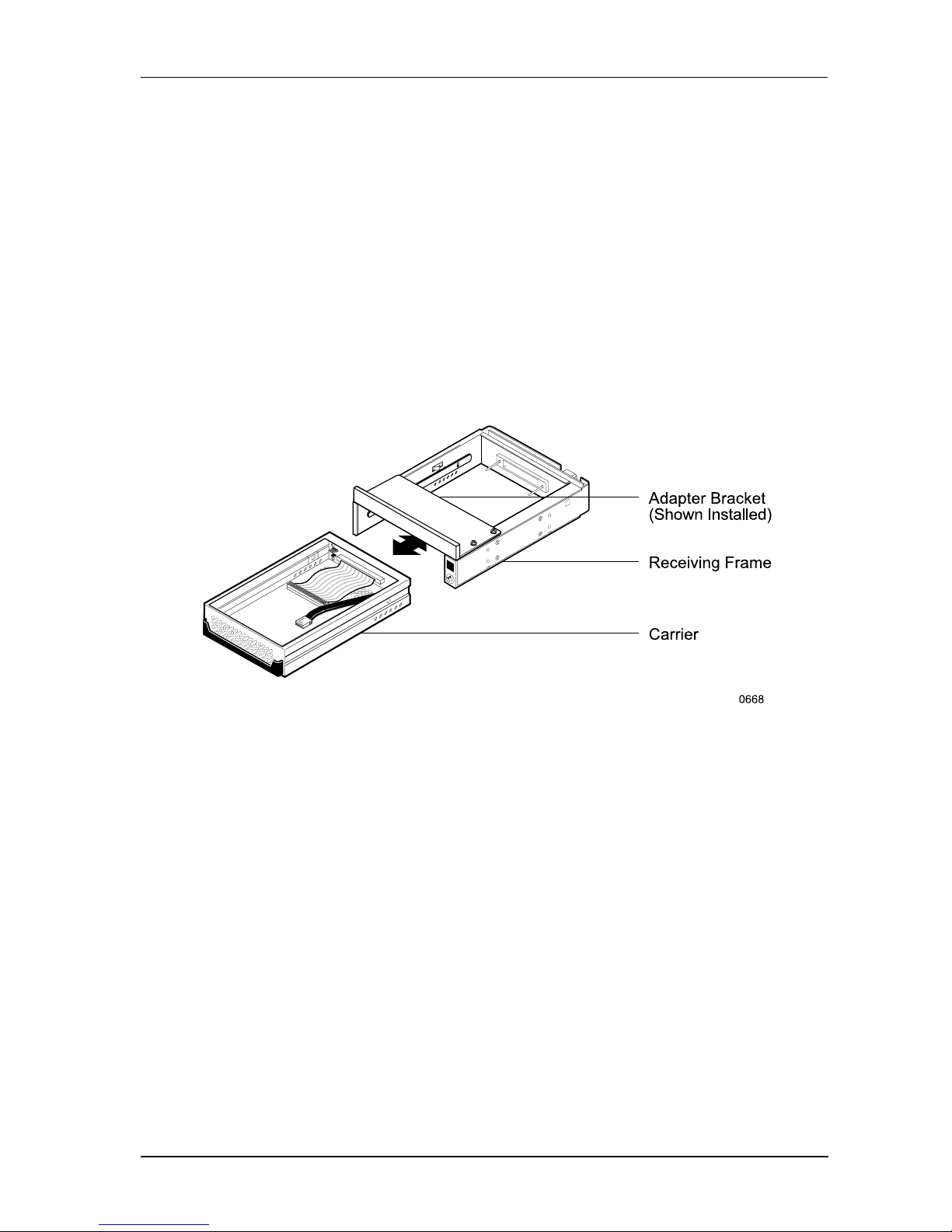
Figure 2: DE75i-S Receiving Frame and Carrier
This User's Guide describes the steps required to install the StorCase Data Express
DE75i-S removable enclosure inside a computer peripheral bay or external expansion chassis.
This guide supplements documentation provided with the host computer system, operating
system, and the drive to be installed within the Data Express carrier.
GeneralDescription
The StorCase Technology Data Express® DE75i-S is a removable drive carrier and receiving
frame designed to provide durable and reliable mounting for 3.5 form factor, low-profile (up
to 1" high), SCSI drives (Figure 2).
The DE75i-S allows a drive to be removed and transported to another DE75i-S-equipped
computer or expansion chassis, and also provides the ability to secure sensitive data by
removing and storing the drive safely for future use.
Page 11
4 Introduction
StorCase Technology, Inc. DE75i-S User's Guide - Rev. A01
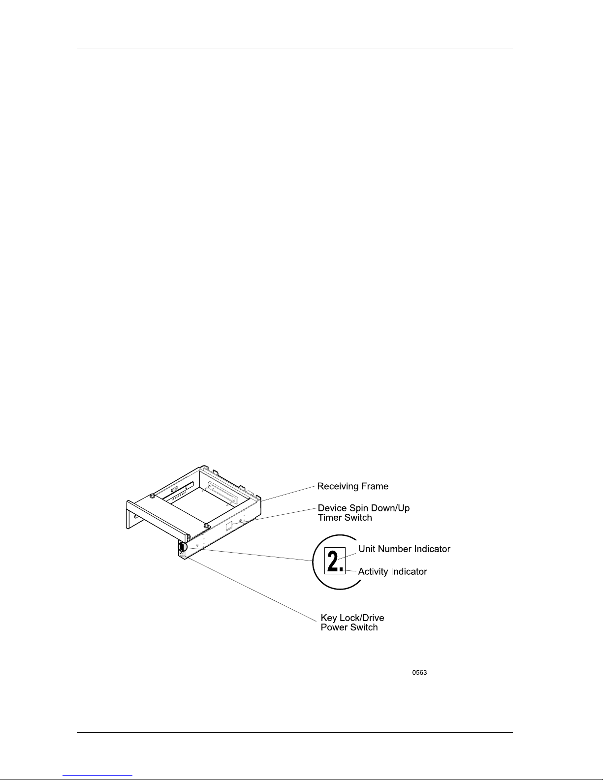
Figure 3: Receiving Frame Front Panel
ReceivingFrameFrontPanel
(Figure 3)
Key Lock and Power Switch (Figure 3) - This key switch assures proper seating
of the drive carrier within the receiving frame, turns power to the drive carrier on
and off, and prevents unauthorized removal or installation of the carrier. For the
computer to access data on the DE75i-S drive, the key must be turned counterclockwise to the locked position. The key can be configured as either fixed or removable
as shown in Appendix B.
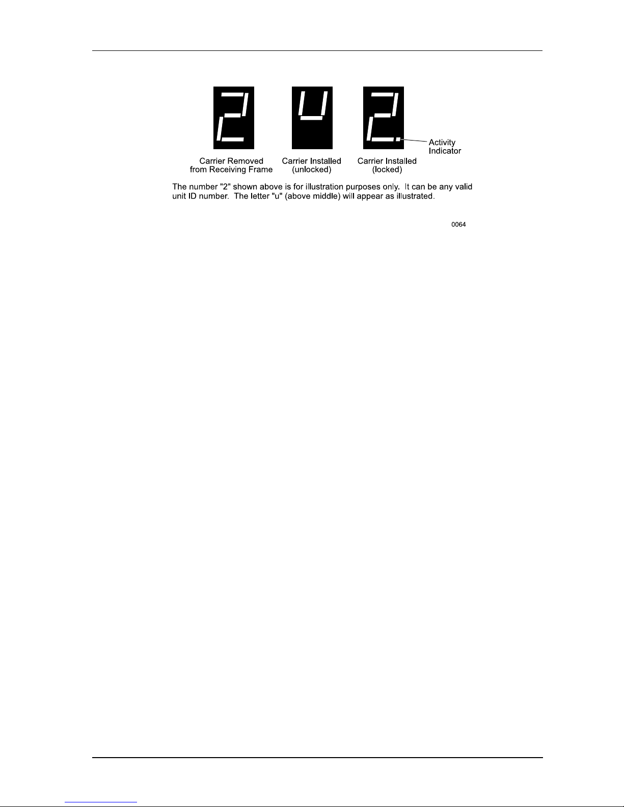
Unit ID Number Indicator (Figures 3 & 4) - This LED displays the physical address
of the DE75i-S device carrier if the carrier is installed and locked in the receiving
frame or if the carrier is removed from the receiving frame. If the carrier is installed
but not locked in the receiving frame, a "u" will be displayed to indicate an unlocked
condition. The unit ID number is selected by means of the unit ID select switch inside
the receiving frame using a special alignment tool supplied with the DE75i-S (see
Figure 10).
The Activity Indicator (Figures 3 & 4) - A small dot next to the unit ID number
illuminates to indicate when the host computer is accessing the data on the
DE75i-S carrier. This dot will flash during communication with the host computer.
Device Spin Down/Up Timer (Figure 3) - This timer controls the length of time that
the unit number display flashes during device spin down/up, providing a visual
indication of drive activity. Refer to Figure 11 for switch settings.
Page 12
Introduction 5
DE75i-S User's Guide - Rev. A01 StorCase Technology, Inc.
Figure 4: Receiving Frame Unit ID Number and Activity Display
Page 13
6 Introduction
StorCase Technology, Inc. DE75i-S User's Guide - Rev. A01
ReceivingFrameRearPanel
(Figure 5)
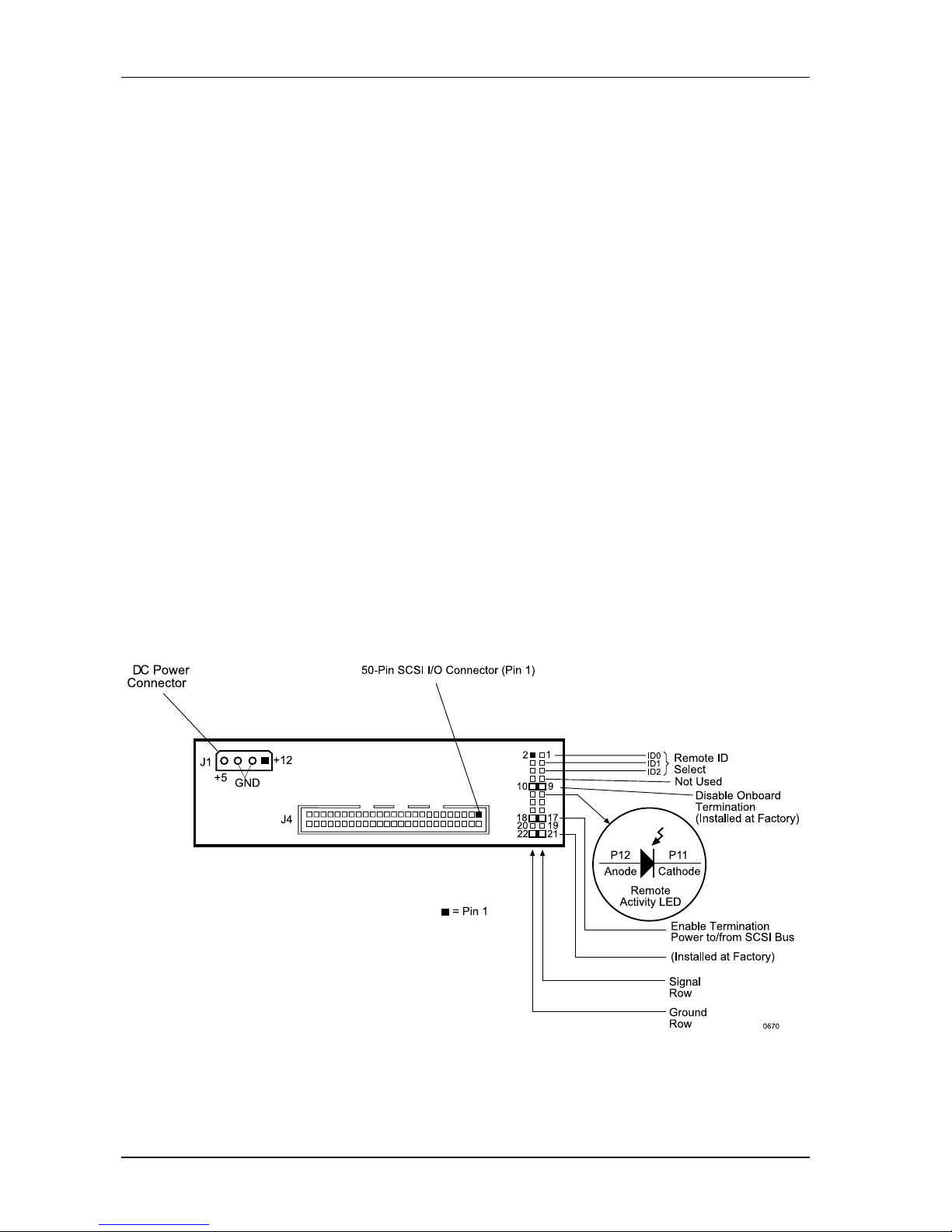
I/O Connector - These connectors provide a standard interface for all SCSI signals
(Figure 5). See Table 2 for pin assignments.
DC Power Connector (J1) - A standard 4-pin DC power connector is used to accept
DC power.
Option Pins
Remote Unit ID Selection - Pins 1-6 of this connector provide unit SCSI ID selection for
the computer system or expansion chassis. For remote ID selection through an expansion
chassis, an appropriate cable must be attached to these pins and the unit ID must be set
to "0". The unit ID can be set with a rotating switch located inside the receiving frame
(Figure 10).
Disable Termination (DT) - A factory-installed jumper on these pins disables termination. Removing this jumper will enable termination. Remove this jumper if the drive is
physically located at the end of a SCSI daisy chain.
Remote Activity LED (RLED) - These pins provide power for a remote LED device
activity indicator (Pin 11=Cathode, Pin 12=Anode).
Enable Termination Power To/From SCSI Bus (TPWR) - This jumper is installed at
the factory.
Figure 5: Receiving Frame Motherboard (Rear View)
Page 14

DE75i-S User's Guide - Rev. A01 StorCase Technology, Inc.
Installation 7
INSTALLATION
InstallingtheDriveintotheCarrier
Preparation
While performing the steps in this section, work on a soft surface to prevent excessive shock
to the drive being installed. Also refer to the manufacturer's documentation provided with the
drive.
NOTE: A #2 Phillips screwdriver will be required during this procedure.
1. Remove the drive from its protective packaging.
2. Plastic Drive Bezel: If the drive to install is equipped with a plastic front bezel,
remove it.
3. SCSI Drive Termination: Disable or remove the termination resistor packs
from the drive. Termination is performed by an external terminator in the DE75iS receiving frame (Figure 5). Refer to the documentation provided by the drive
manufacturer for the location of these terminators or jumpers.
4. SCSI Drive ID Select Jumpers: Locate the SCSI ID select jumper positions on
the drive, and remove any jumper plugs in this area. The SCSI ID cable will be
installed into this section of the drive (Figure 6).
5. SCSI ID Cable: This cable carries the SCSI ID signal between the drive and the
carrier. The signal is transferred to/from the receiving frame via the carrier and
receiving frame mating connectors. The ID cable permits unit ID selection via a
small switch located on the inside of the receiving frame (Figure 10). The DE75iS carrier is supplied with two (2) 3-wire cables. One cable contains 0.1" and
2mm connectors, the other cable uses 0.1" and 1.25mm connectors. One end
of the SCSI ID cable attaches to the carrier signal distribution board (inside the
carrier), the other end of the cable attaches to the ID pins on the drive (Figure
7). Use the appropriate ID cable for your specific drive.
The unit ID cable contains black, brown, and, red wires. The black wire plugs
into the drive pin used to select ID0, the brown wire plugs into the drive pin for
ID1, and the red wire plugs into the drive pin for ID2. Most drive manufacturers
label these pins as ID0, ID1 and ID2, or similar identification. LED activity is handled
through the Data Express logic (Figure 5).
Drives use a row of pins to provide ground to the ID signals. This row of pins
is not used for the Data Express installation. One end of the unit ID cable connects
to the signal row of ID pins on the drive. The other end of this cable attaches
to the ID select connector on the inside of the carrier (Figures 6 & 7). Refer to
the drive manufacturer's documentation for more information.
Page 15
StorCase Technology, Inc. DE75i-S User's Guide - Rev. A01
8 Installation
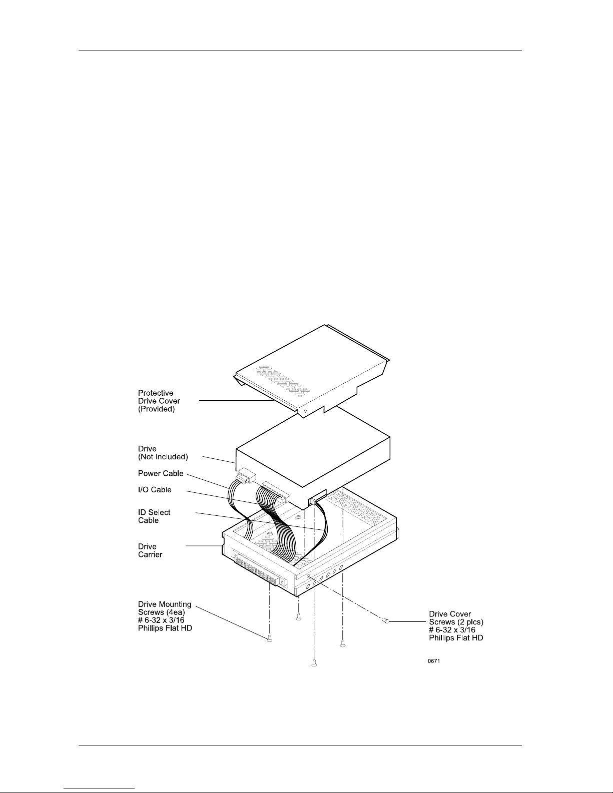
Figure 6: Drive Installation Assembly
Installation
1. Attach the I/O cable from the carrier board to the drive (Figure 6).
2. Attach the 4-pin power cable from the carrier board to the drive (Figure 6).
3. Attach the appropriate ID select cable to the carrier board connector (Figure
7).
4. Carefully insert the drive into the carrier at an angle, cable-end first. Make sure
that none of the cables are pinched. Lower the front of the drive carefully
into place. Fasten the drive into the carrier with four (4) # 6-32 Phillips Flat Hd.
screws provided.
5. Attach the provided drive cover with two (2) #6-32 Phillips Flat Hd. screws.
Page 16
DE75i-S User's Guide - Rev. A01 StorCase Technology, Inc.
Installation 9
TYPICAL 2MM DRIVE ID PIN CONFIGURATION
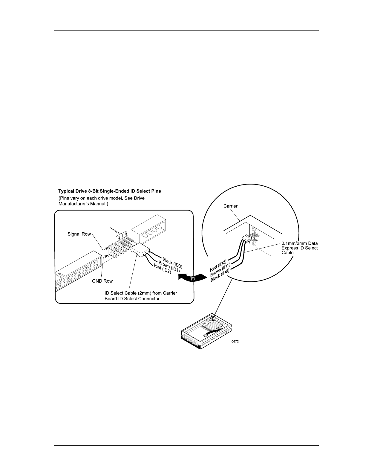
Figure 7 illustrates a typical SCSI ID select connection to a drive with 2mm ID select pins. In
most cases, the drive manufacturer labels each pair of SCSI ID select pins in their significant
bit order (0, 1, 2 as shown in Figure 7). In other cases, the manufacturer does not label these
pins in their significant bit order, but instead, assigns pin numbers only. In any case, all odd
numbered pins or all even numbered pins will be the signal row. The wires on the wire harness
connect to the positive pin (or signal pins) on the drive. Refer to the device manufacturer's
documentation for additional pin numbering and jumper option information.
Attach the ID select cable to the drive using the 2mm connectors. Align the ID0 pin with the
black wire. Attach the other end of the ID select cable to the ID select connector located on
the carrier board, inside the carrier. Refer to the manufacturers documentation to disable
termination on the drive.
Figure 7: Typical SCSI ID Select Connections (2mm Drive Pins)
Page 17
StorCase Technology, Inc. DE75i-S User's Guide - Rev. A01
10 Installation
InstallingtheReceivingFrame
The drive should be installed into the carrier before installing the receiving frame into the
mounting bay of a computer or expansion chassis.
NOTE: Use a #2 Phillips screwdriver during this procedure.
1. Turn OFF power to the computer.
2. Open the computer system according to the manufacturers instructions. If
necessary, temporarily remove any expansion boards that may make installation
difficult.
3. To select the DE75i-S unit ID remotely through the computer system or external
expansion chassis, the appropriate cable from the system must be attached to
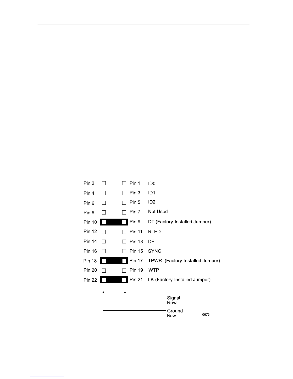
option Pins 1-8 on the rear of the receiving frame (Figure 8). Set the unit ID to '0'
for remote ID selection (Figure 10).
Figure 8: Receiving Frame Motherboard Option Pins
Page 18

DE75i-S User's Guide - Rev. A01 StorCase Technology, Inc.
Installation 11
PIN Signal Function
1 ID0 SCSI ID
2 GND Ground
3 ID1 SCSI ID
4 GND Ground
5 ID2 SCSI ID
6 GND Ground
7 ID3 Not Used
8 GND Ground
9 DT Disable On Board Terminator
10 GND Ground
11 RLEDC Remote LED Cathode
12 RLEDA Remote LED Anode
13 DFAULT Force Drive Fault Signal to Display
14 GND Ground
15 SYNC Drive Synchronization Signal
16 GND Ground
17 TPWR Terminate Power To/From SCSI Bus
18 GND Ground
19 WTP Reserved
20 GND Ground
21 LKA Disable Isolator Functions
22 LKB Disable Isolator Functions
Table 1: Option Pin Signal Descriptions
Page 19
StorCase Technology, Inc. DE75i-S User's Guide - Rev. A01
12 Installation
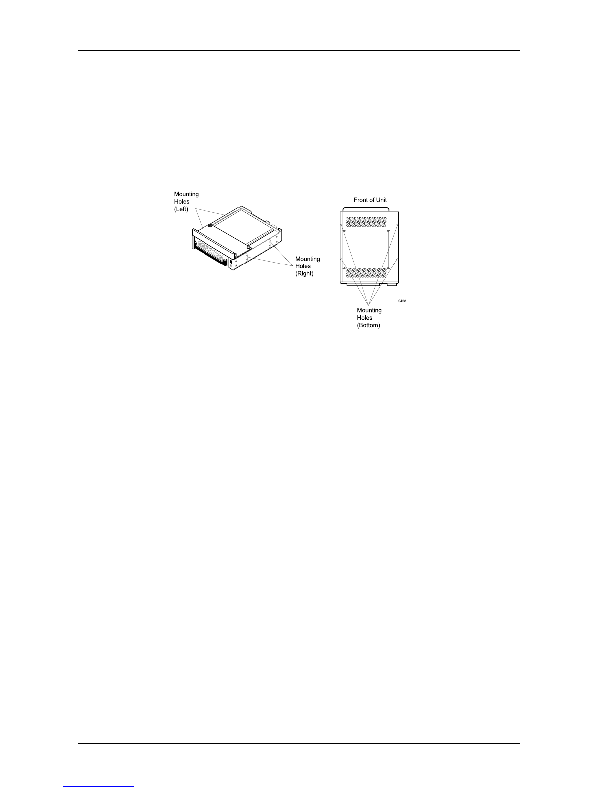
Figure 9: Receiving Frame Mounting Holes
5. Adjust the front of the receiving frame so the carrier slides freely in and out on the
receiving frame guides. The position of adjoining peripheral units may require
adjustment.
6. To connect a drive to a remote activity LED in the computer system or expansion chassis,
connect the appropriate cable(s) to the receiving frame motherboard option Pins 11&
12 as shown in Figure 5.
7. Connect the I/O cable from the host adapter to the receiving frame. The Pin 1 indicator
on the cable must be properly aligned. Refer to Figure 5 for the correct Pin 1 location.
8. When installing the DE75i-S into a computer system, make sure that only the last SCSI
device is terminated. If the DE75i-S is at the end of a daisy chain, the receiving frame
termination must be enabled by removing the appropriate jumper. If the
DE75i-S is in the middle of a daisy chain, termination should be disabled (factory-installed
jumper) at option Pins 9 & 10 (Figure 8).
In most cases, if installing the DE75i-S into an external expansion chassis, the factory
installed jumper on option Pins 9 and 10 (disable termination) should be left in place.
Termination will be handled by an external terminator on the expansion chassis.
9. Connect the power cable from the DC power supply in the computer or expansion
chassis to the power connector on the DE75i-S receiving frame. Refer to Figure 5 for
the receiving frame power connector location.
4. With the drive carrier locked into place inside the receiving frame, install the
DE75i-S receiving frame into the drive opening in the computer or expansion
chassis. Use the appropriate guides to position the DE75i-S, and fasten it into
place with four (4) #6-32 x 1/4 screws provided. Figure 9 illustrates the location
of the mounting holes. Mounting holes are provided on each side and the bottom of
the receiving frame to accommodate a variety of mounting configurations. Use the
mounting holes which best suit the computer or expansion chassis configuration.
Page 20

DE75i-S User's Guide - Rev. A01 StorCase Technology, Inc.
Installation 13
10. Replace any expansion boards that may have been removed earlier. Replace the
system cover according to the manufacturers instructions.
11. Reconnect any system or peripheral cables removed earlier.
12. If the DE75i-S has been installed into an external expansion chassis, connect the SCSI
and power cables to the chassis. If the expansion chassis is at the end of a daisy
chain, make certain that it is properly terminated. Refer to the computer system and
expansion chassis manuals for information on how to do this. Turn on the expansion
chassis power before turning on the computer system power.
13. Turn ON power to the computer. If the installation has been successful, and all cables
have been properly attached, the system should boot normally. Although the
computer may not recognize the DE75i-S yet, the appropriate front panel LED
indicators on the Data Express should illuminate. If the system does not boot properly,
there could be a SCSI ID conflict. Refer to the following section "Selecting the Unit
Number" for further information.
NOTE: The lock on the DE75i-S receiving frame functions as a lock and a DC power
switch for the carrier unit. The lock must be engaged (turned counterclockwise)
in order to supply power to the carrier and installed drive unit.
14. The new drive may need to be formatted or initialized prior to use with the operating
system and applications software. Additionally, an appropriate driver may need to
be installed for the host controller to recognize the newly installed device. Refer to
the drive and/or computer manufacturer's documentation for formatting information.
Refer to the host controller instructions for driver information.
SelectingtheUnitID Number
Each SCSI device on the computer system requires a separate SCSI ID number.
8-bit SCSI interface protocol permits 8 (0-7) unique SCSI ID numbers. Usually, ID7 is reserved
for the host controller. If the computer system has any internal or external SCSI devices, some
ID numbers may already be reserved. For instance, if the computer system is already equipped
with an internal SCSI hard drive, the drive may be designated as SCSI device "0". Refer to
the computer system documentation for additional information.
1. Verify that power is turned ON to the DE75i-S receiving frame by turning on the
computer or external expansion chassis. A number should appear in the unit ID display
window if the carrier is locked into place.
Page 21
StorCase Technology, Inc. DE75i-S User's Guide - Rev. A01
14 Installation
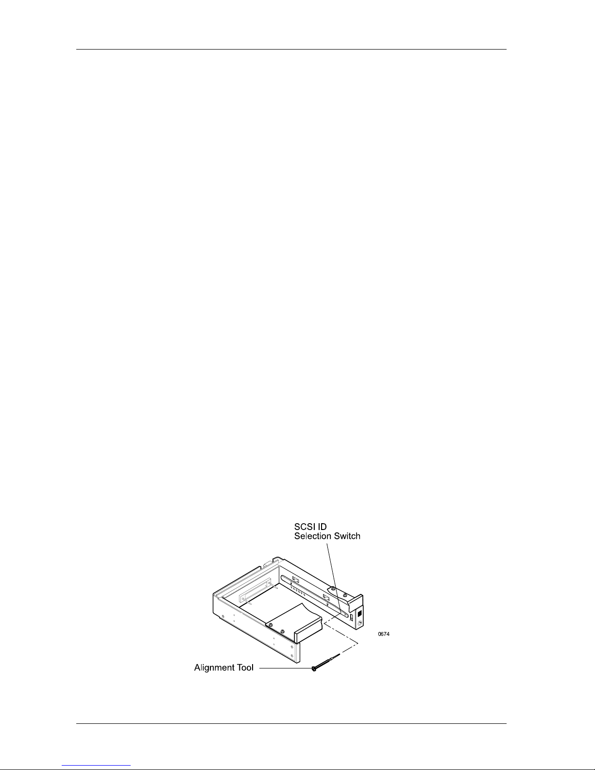
Figure 10: Unit ID Select Switch Location
WARNING: Unlocking the carrier unit switches DC power off to the drive. Since
drives require a short amount of time to spin down, allow at least 15
seconds before pulling the carrier unit out of the receiving frame to
avoid possible damage to the drive.
3. A "u" will be displayed once the drive has completed spin down and is ready to be
removed from the receiving frame. The indicator will return to the SCSI ID number when
the carrier is removed from the receiving frame.
4. Use the alignment tool supplied with the DE75i-S to select the ID number of the disk drive.
Refer to Figure 10 for the location of the ID select switch inside the receiving frame.
WARNING: Selecting an invalid ID number, or selecting the same unit ID number on
different devices may cause unpredictable results and the computer
system may not recognize the installed device(s). If the computer
system can not recognize the boot disk, the computer system may fail
to start-up properly.
5. After selecting an appropriate unit ID number, replace the DE75i-S carrier in the
receiving frame, and LOCK IT IN PLACE.
6. If the DE75i-S has been installed into an external expansion chassis, verify that power
is on to the chassis and that the last device in the SCSI daisy chain is properly terminated.
7. Reboot the computer system.
2. Unlock the DE75i-S carrier from the receiving frame. The unit number will begin flashing,
indicating that the drive is spinning down. DO NOT REMOVE THE CARRIER FROM THE
RECEIVING FRAME WHILE THE UNIT ID NUMBER IS FLASHING. The length of time that
the unit ID number flashes is controlled by a small timing switch located on the side of
the receiving frame. Refer to Figure 11 for adjusting the spin down/up timer.
Page 22
DE75i-S User's Guide - Rev. A01 StorCase Technology, Inc.
Installation 15
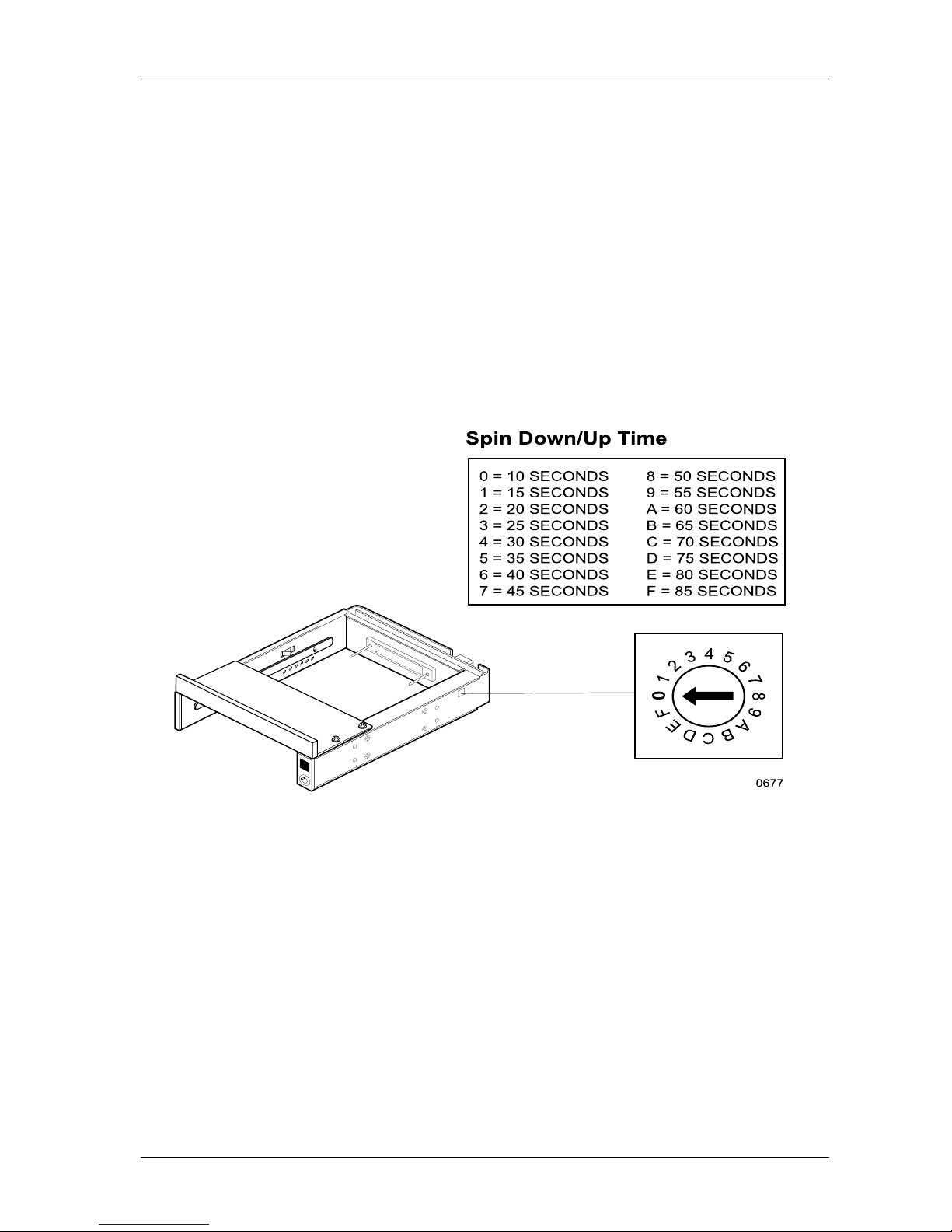
Figure 11: Device Spin Down/Up Timer
Adjusting the Spin Down/Up Timer
The timer for device spin down is controlled by a small selector, located in a cutout on the side
of the DE75i-S receiving frame as shown in Figure 11. The amount of time required for a drive
to spin down is approximately 15 seconds or more. This number can vary depending on the
type of SCSI device and manufacturer (some drives may require 45 seconds or more). The
factory configuration is set for 20 seconds. A different delay time may be selected with the
provided adjustment tool. Refer to the SCSI device manufacturers manual for more information
on required device spin down/up time.
Page 23
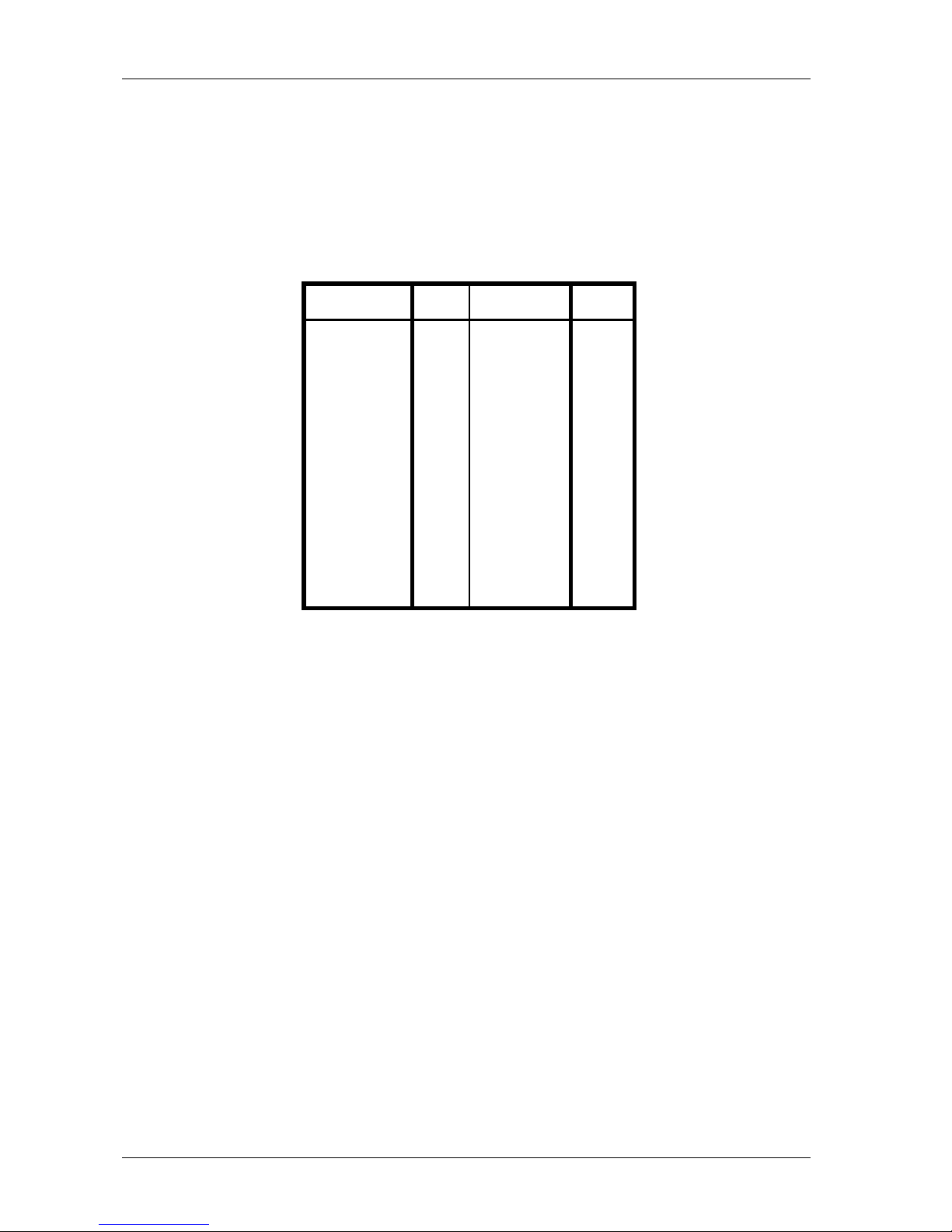
StorCase Technology, Inc. DE75i-S User's Guide - Rev. A01
16 Installation
Signal Pin Signal Pin
-DB(0) 2 Ground 30
-DB(0) 4 -ATN 32
-DB(0) 6 Ground 34
-DB(0) 8 -BSY 36
-DB(0) 10 -ACK 38
-DB(0) 12 -RST 40
-DB(0) 14 -MSG 42
-DB(0) 16 -SEL 44
-DB(0) 18 -C/D 46
Ground 20 -REQ 48
Ground 22 -I/O 50
Ground 24
TRMPWR 26
Ground 28
Table 2: SCSI Interface Connector Pin Assignments
SCSI Interface Connector
The SCSI interface connector pin assignments are supplied for your convenience.
NOTE: All odd pins except Pins 23, 25, 27 and 29 are connected to ground. Pin
25 is left open.
CAUTION: Pin 25 must not be connected to ground at the HOST end or the drive end
of the cable. If the I/O connector is accidentally plugged upside down,
terminator power on Pin 26 will be shorted to ground.
The minus (-) sign next to the signals indicates asserted state is the low
voltage of the two levels used for logic signals.
Pins 23, 27, and 29 are reserved.
Page 24

Appendix A - Specifications/Dimensions 17
DE75i-S User's Guide - Rev. A01 StorCase Technology, Inc.
APPENDICES
Page 25
18 Appendix A - Specifications/Dimensions
StorCase Technology, Inc. DE75i-S User's Guide - Rev. A01
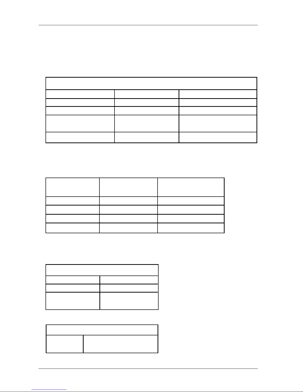
SCSI Data Express subsystems conform to the Small Computer Systems Interface (SCSI)
Standard set by the American National Standards Institute (ANSI).
Environmental Specifications
Operating Storage
Ambient Temperature -5° C to 50° C -45° C to 75° C
Relative Humidity
( 1 )
10% to 80% 10% to 90%
Altitude -1000 to 50,000 ft -1000 to 50,000 ft
-304m to 15240m -304m to 15240m
Shock
(2)
10g 60g
(1)
Non-condensing with maximum gradient of 10% per hour.
(2)
11 msec pulse width 1/2 sine wave.
Physical
Specifications Carrier Receiving Frame
Height 1.07" (27.2mm) 1.13" (28.7mm)
(1)
Width 4.67" (118.6mm) 5.75" (146.1mm)
Depth 7.38" (187.5mm) 8.15" (207.0mm)
Weight 1.1lb. (0.50kg) 1.1lb (0.50kg)
(2)
Chassis Reliability/Maintainability
MTBF 500,000 Hours
MTTR 5 Minutes
Preventive
Maintenance None
Electrical Specifications
Input +5V 65mA
+12V 400µA
(1)
With adapter bezel removed.
(2)
With carrier removed.
Appendix A - Specifications/Dimensions
Page 26
Appendix A - Specifications/Dimensions 19
DE75i-S User's Guide - Rev. A01 StorCase Technology, Inc.
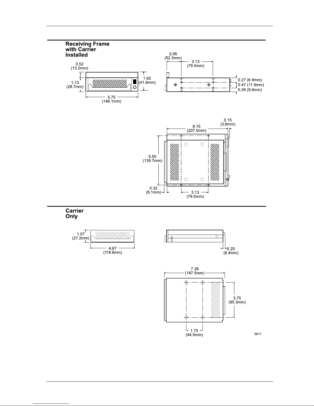
Figure A-1: DE75i-S Physical Dimensions
(Dimensions are for reference only)
Page 27
StorCase Technology, Inc. DE75i-S User's Guide - Rev. A01
20 Appendix B - Attaching the ON/OFF Key
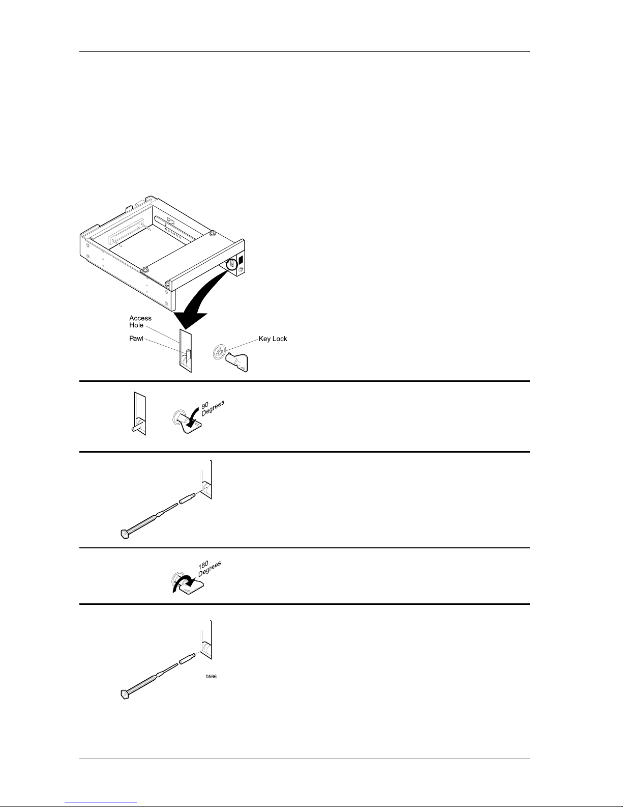
Figure B-1: Attaching the ON/OFF Key
Appendix B - Attaching the ON/OFF Key
The following information will provide the necessary steps to attach the ON/OFF key to the
key lock mechanism so that it is non-removable, preventing accidental key loss. The procedure
can be reversed at a later date to revert back to a removable key.
1. Make certain power is OFF to the receiving
frame.
Locate the rectangular shaped key lock mechanism access hole on the inside of the receiving
frame. Note that the pawl is in an upright position.
Insert the key into the key lock.
2. Rotate the key 90 degrees counterclockwise so
that the pawl is visible in the access hole as
shown in the figure at left.
3. Using the provided alignment tool, unscrew and
remove the pawl from the access hole.
4. Rotate the key 180 degrees clockwise.
5. Reinstall the pawl into the access hole with the
alignment tool.
Your key is now attached to the key lock mechanism.
Page 28
DE75i-S User's Guide - Rev. A01 StorCase Technology, Inc.
Appendix C - Optional Accessories 21
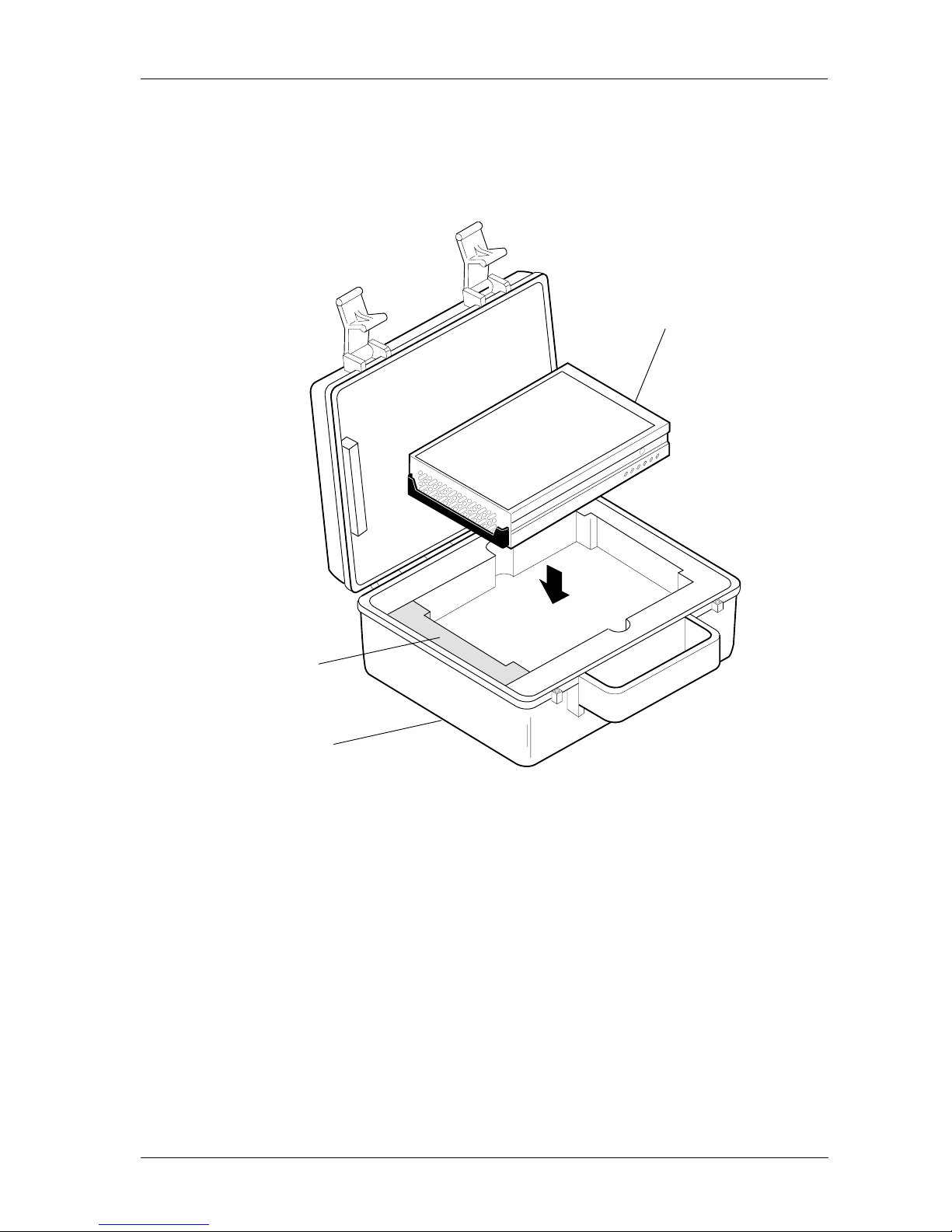
Figure C-1: Carrying Case
The optional molded plastic carrying case is designed to transport the DE75i-S carrier
from one location to another in a safe, impact and moisture resistant environment. Its
compact dimensions, 7 long x 9 wide x 3.5 high, make it easy to carry and to store. The
foam lining is contoured to fit a single DE75i-S carrier with a 1-inch form factor (remove
the foam piece shown in the illustration above). Contact StorCase for further details and
ordering information.
Drive
Carrier
DX300-DE-C
Carrying Case
0524
Remove this
Piece of Foam
Appendix C - Optional Accessories
Carrying Case
Page 29

StorCase Technology, Inc. DE75i-S User's Guide - Rev. A01
22 Appendix C - Optional Accessories
This Page Left Blank Intentionally.
Page 30

DS75i-S User's Guide - Rev. A00 StorCase Technology Inc.
Reader's Comments 23
Reader's Comments
Please take a few moments when your computer system is up and running to send us your
ideas and suggestions for improving our products and documentation. Did the installation go
smoothly for you? Are there any changes you would like us to make, either with the hardware
itself, or with the installation instructions? Everyone at StorCase Technology is working
toward the goal of providing you with the highest quality, most cost effective, products
available on the market, and we need your comments to guide our efforts. We look forward
to hearing from you soon!
Date:
Your Name:
Address:
Telephone: ( )
To mail this page, carefully remove it from the manual, fold it, staple or tape it shut, and drop
it in the mail. To FAX this page, carefully remove it from the manual (or make a photocopy) and
FAX it to us at (714) 438-1847. Thank you for taking the time to help us make our products
better.
Page 31
FOLD ALONG THIS LINE AND STAPLE SHUT
CUT ALONG THIS LINE FROM BOTTOM TO TOP OF PAGE
BUSINESS REPLY MAIL
POSTAGE WILL BE PAID BY ADDRESSEE
NO POSTAGE
NECESSARY
IF MAILED
IN THE
UNITED STATES
FIRST CLASS MAIL PERMIT NO. 10686 SANTA ANA, CA
TECHNOLOGY CORPORATION
17600 NEWHOPE STREET
FOUNTAIN VALLEY CA 92708-9885
17600 NEWHOPE STREET
FOUNTAIN VALLEY CA 92708-9885
 Loading...