

Page 1

SWXTL-BL 50/100 GB, 5-Cartridge
DLT Tape Drive Mini-Library
User’s Guide
Order Number EK-SM1TC-UG. A01
Page 2

Page 3

02-17-94: Dick Desjardins asked me to work out a convenient way to establish the correct title placement for
the StorageWorks covers, which will have a diecut aperture in the cover, with the title showing through.
Dick says that Al Mayer’s design specs call for the title to be set in 42-point Palatino. At the same time,
however, the design specs provided by the printing department indicate the text is to fit in a space that is
designed to be 2.17” high by 5.33” wide, with the bottom edge being 6.5” from the bottom of the page and the
left edge being 2.25” from the left edge of the page, with the aperture having slightly rounded corners.
The obvious approach should be to create that page (via a template) either as a separate document or as a
separate section, with the Page Setup values adjusted to leave only the actual space available. The writer then
must make his/her title fit within that space—which can be encouraged by supplying a “dummy” text string
with the desired font and font size, with the writer then simply replacing that text with his/her title—which
will be displaced to the next page of the work document if it is too long. The need to include any other text on
the page (such as a repetition of the StorageWorks log at the top and/or the Digital address at the bottom) can
be taken care of simply by preprinting a stock of such pages, to obtain the unchanging information, and then
using the preprinted page when it is time to print a cover.
The cover setup is relatively straightforward. To compensate for the rounded corners, I simply added
0.05” to the applicable measurements, finding that the Page Setup utility will accept some values but round
others off. At the moment, for example, the cover aperture, shown in Section 1 of this file, is set to be 2.4”
below the top of the page, 2.4” from the left edge (2.33” rounded off), 6.55” from the bottom, and 1.0” (0.97”
rounded off) from the right side. This leaves a printable “hole” that measures 2.05” high by 5.1” wide.
As should be patently obvious, however, this space restriction severely limits how much text can be fit
into that space ... which becomes a problem to us, because the engineering minds that create these titles like
Germanic constructions full of semi-informative adjectives.
Since a “point” equals 0.01384 inch, and since WinWord presumably adds a standard 2-point (or more)
gutter spacing between lines, this means that each line of text will consume 44 x 0.01384 = 0.609 inches,
which means that three lines (1.827”) will fit comfortably within the 2.05”-high aperture—but that those lines
will be limited to a length of approximately 30 picas each, meaning that there will not be space for more than
two or three words per line (four if they are fairly short words).
Experimentation indicates that this all changes with different fonts, however. I find that I can get three
lines of Times New Roman at 42 points and four lines at 31 points ... but that Palatino (on my home system)
requires reduction to 41 points (as currently shown here) in order to get three lines, meaning that restricting
the title to 42 points will limit the title to two lines of text, containing between four and eight words!
02-18-94: All of that went out the window with the further clarification that the aperture also had to include a
line under the title, followed by the publication category (User Manual, etc.), followed—with an appreciable
space—by the order number ... with the additional news that the coversheet font was Arial (which is a
TrueType font that gets translated into Helvetica in our print setup, anyway).
So—I’ve incorporated those into the template setup, finding that the title is restricted to two lines for a
total of three or four words at 42 points ... and works down from there.
02-18-94: While I was typing that, it changed again. The semiofficial word currently is that the title will be
24-point Palatino, while the category will be 14-point Helvetica and the order number will be 9-point
Helvetica.
I’ve also set up the second page of this template to print the StorageWorks logo, currently set up at a size
that met Carl Peterson’s approval, which will be preprinted on the sheet used for the title page. For the record,
the preprinted page has to be put in the 4M machine upside down (logo image on bottom), bottom end first
into the paper tray.
Page 4

First Edition, April 1994
The information in this document is subject to change without notice and should not be construed as a commitment by Digital
Equipment Corporation. Digital Equipment Corporation assumes no responsibility for any errors that may appear in this
document.
Restricted Rights: Use, duplication, or disclosure by the U.S. Government is subject to restrictions as set forth in
subparagraph (c) (1) (ii) of the Rights in Technical Data and Computer Software clause at DFARS 252.227-7013.
Digital Equipment Corporation does not give a warranty of any kind regarding the fitness or applicability of the information
content for a particular purpose. The user assumes all responsibility for understanding the interrelationships of this enclosed
information with other affected software or system products.
The disclosure of this information does not grant to the user a license under any patents, pending patents, trademarks, or
copyrights or other rights of Digital Equipment Corporation, or of any third party.
FCC Notice: This equipment generates, uses, and may emit radio frequency energy. The equipment has been type tested
and found to comply with the limits for a Class A computing device pursuant to Subpart J of Part 15 of FCC Rules, which are
designed to provide reasonable protection against such radio frequency interference when operated in a commercial
environment. Any changes or modifications made to this equipment may void the user's authority to operate the equipment.
Operation of this equipment in a residential area may cause interference, in which case the user, at his own expense, may
be required to take measures to correct the interference.
Copyright © Digital Equipment Corporation 1994
All Rights Reserved
Printed in U. S. A
The following are trademarks of Digital Equipment Corporation:
StorageWorks, and the Digital Logo.
All other trademarks and registered trademarks are the property of their respective owners.
Page 5

Contents
Revision Record................................................................................................................... vi
About This Manual............................................................................................................vii
1 Introduction
1.1 Product Overview ...............................................................................................1–1
1.1.1 Fast Data Transfer Rate.................................................................................1–1
1.1.2 High Capacity...............................................................................................1–1
1.1.3 Compaction ..................................................................................................1–2
1.1.4 Media Durability...........................................................................................1–2
1.1.5 Compatibility................................................................................................1–2
1.1.6 Code Update Capability................................................................................1–3
1.1.7 Embedded Diagnostics..................................................................................1–3
2 Installing and Operating the Mini-Library
2.1 Unpacking the Mini-Library................................................................................2–1
2.2 Power and SCSI Bus Terminator Connections.....................................................2–2
2.3 Introduction to the Mini-Library..........................................................................2–5
2.4 Configuring and Installing the Mini-Library........................................................2–6
2.4.1 Configuration Guidelines..............................................................................2–6
2.4.2 SCSI Cable Connection................................................................................2–6
2.5 POST Test..........................................................................................................2–6
2.6 Mini-Library Operator Control Panel ..................................................................2–7
2.7 Key Lock............................................................................................................2–9
2.8 Operator Control Panel Locked (Disabled)..........................................................2–9
2.9 Operator Control Panel Unlocked (Enabled)......................................................2–10
2.10 Setting the SCSI ID of the Mini-Library............................................................2–10
2.11 Select Density...................................................................................................2–10
2.11.1 Front Panel Density Select Mode................................................................2–11
2.11.2 Programmable Host Selection via Your Operating System..........................2–12
2.11.3 Native Default Density 10 GB and Compress..............................................2–12
2.12 Default Operating Modes..................................................................................2–12
2.12.1 Normal Mode .............................................................................................2–12
2.12.2 Density Select Mode...................................................................................2–13
2.12.3 SCSI ID Select Mode..................................................................................2–13
2.12.4 Code Update Mode.....................................................................................2–14
2.13 Tape Cartridge Description ...............................................................................2–14
2.13.1 Cartridge Write-Protect Switch................................................................... 2–14
2.13.2 Data Protection........................................................................................... 2–15
2.13.3 Ordering Cartridges ....................................................................................2–15
Tape Mini-Library User’s Guide iii
Page 6

StorageWorks Tape Mini-Library
2 Installing and Operating the Mini-Library (Con't)
2.14 Description of the Magazine.............................................................................2–16
2.14.1 Inserting a Cartridge into the Front of the Magazine ...................................2–16
2.15 When to Use the Cleaning Cartridge.................................................................2–17
2.16 Removing a Cartridge from the Magazine.........................................................2–18
2.17 Removing the Magazine from the Mini-Library................................................2–19
2.18 Installing the Magazine into the Mini-Library...................................................2–19
2.19 Selecting a Cartridge from the Magazine ..........................................................2–19
2.20 Loading the Cartridge ......................................................................................2–19
2.21 Unloading the Cartridge....................................................................................2–20
2.22 Opening the Magazine Door.............................................................................2–20
3 Code Update (From Tape)
3.1 Code Update Overview.......................................................................................3–1
3.1.1 Updating Code on a Standalone SWXTL-BL ...............................................3–1
3.2 Code Update Procedure ......................................................................................3–1
3.2.1 Updating the Code on the SWXTL-BL.........................................................3–2
3.2.2 Interpreting the Results.................................................................................3–3
4 Troubleshooting
4.1 Mini-Library Push-button Conditions.................................................................4–1
4.2 Backup Operation Failures..................................................................................4–2
4.3 Avoiding Basic Problems...................................................................................4–2
4.4 Error Conditions.................................................................................................4–3
4.4.1 Magazine Error Condition Cases..................................................................4–3
4.4.2 Loader Error Description..............................................................................4–3
4.4.3 Clearing the Loader Error............................................................................. 4–3
4.4.4 Drive Error Description................................................................................4–3
4.4.5 Clearing a Drive Error..................................................................................4–4
4.4.6 Controller Error Description.........................................................................4–4
4.4.7 Clearing the Controller Error........................................................................4–4
4.5 Power Problems..................................................................................................4–4
Appendix A Specifications............................................................................................A–1
Appendix B Product Notes for Novell™ and MS-DOS™ ....................................... B–1
Index ............................................................................................................................Index–1
Reader Comment Form............................................................................Inside Back Cover
Figures
1-1 SWXTL-BL Tape Mini-Library..........................................................................1–2
2-1 Shipping Screw under the Mini-Library..............................................................2–3
2-2 Mini-Library Rear Panel.....................................................................................2–3
2-3 Mini-Library Front Panel....................................................................................2–4
2-4 Mini-Library Operator Control Panel..................................................................2–7
2-5 Tape Cartridge Write-Protect Switch................................................................2–15
iv Tape Mini-Library User’s Guide
Page 7

Figures (Con't)
2-6 SWXTL-BL Magazine......................................................................................2–16
2-7 Inserting a Cartridge into the Magazine.............................................................2–17
2-8 Removing a Cartridge from the Magazine.........................................................2–18
4-1 Opening the Cartridge Door to Check the Tape Leader........................................4–2
Tables
1-1 Read/Write Cartridge Compatibility....................................................................1–3
2-1 Mini-Library Components...................................................................................2–1
2-2 Mini-Library SCSI Interface Cables....................................................................2–2
2-3 Adding a SCSI Bus Terminator...........................................................................2–4
2-4 SCSI-2 Command Conditions.............................................................................2–5
2-5 Configuration Guidelines....................................................................................2–6
2-6 POST Test Messages ..........................................................................................2–7
2-7 POST Test Analysis............................................................................................2–7
2-8 Operator Control Panel Functions .......................................................................2–8
2-9 Operator Control Panel Display Messages...........................................................2–8
2-10 Results of not Using or Using Density Select Mode..........................................2–12
2-11 Normal Mode Definitions.................................................................................2–13
2-12 Density Select Definitions.................................................................................2–13
2-13 SCSI ID Select Mode........................................................................................2–14
2-14 Before Loading the Cartridge............................................................................2–15
2-15 Cartridge Order Numbers..................................................................................2–15
2-16 Setting the Write-Protect Switch.......................................................................2–16
2-17 When to Use the Cleaning Cartridge................................................................. 2–17
2-18 Cartridge Loading Sequence..............................................................................2–20
2-19 Unloading the Cartridge....................................................................................2–20
2-20 Opening the Magazine Door..............................................................................2–21
3-1 Code Update Results...........................................................................................3–3
4-1 Mini-Library Push-button Conditions..................................................................4–1
A-1 Mini-Library Specifications ...............................................................................A–1
A-2 DLT2000 Tape Drive Specifications..................................................................A–2
A-3 SCSI Command Set...........................................................................................A–3
Contents
Tape Mini-Library User’s Guide v
Page 8

Revision Record
This Revision Record provides a concise publication history of this guide. It lists the manual revision levels,
release dates, and reasons for the revisions. It also describes how the changes to affected pages are
marked in the guide.
The following revision history lists all revisions of this publication and their effective dates. The
publication part number is included in the Revision Level column, with the last entry denoting the
latest revision. This publication supports the StorageWorks SWXTL-BL five-cartridge tape drive
mini-library.
Revision Level Date Summary of Changes
EK-SM1TC-UG. A01 April 1994 Original release
Tape Mini-Library User's Guide vii
Page 9

StorageWorks 4 mm Cassette Tape Drive
x Utility for Novell NetWare / preliminary
Page 10

About This Guide
This section identifies the users of this guide and describes the contents and structure. In addition, it
includes a list of conventions used in this guide.
StorageWorks 50/100 GB, 5-Cartridge, DLT Tape Drive Mini-Library User's Guide
This guide provides product overview, installation, operation, and maintenance
information for the 50/100 GB, 5-Cartridge, DLT Tape Drive Mini-Library.
Intended Audience
This guide is intended for people who will install, operate, and maintain the tape drive
mini-library.
Document Structure
This guide contains the following chapters:
Chapter 1: Introduction
Introduction gives an overview of the SWXTL-BL 50/100 GB, tape drive mini-library,
describes its components, and discusses the drive features.
Chapter 2: Installing and Operating the Mini-Library
Installing and operating the mini-library describes unpacking, cable connections,
configuring and installing the mini-library, setting the SCSI ID address, and the
mini-library POST test. It also describes all of the functions of the mini-library operator
control panel and the tape cartridge cassette.
Chapter 3 Code Update (From Tape)
Code Update (From Tape) describes the code-update procedure for updating the code
of the drive controller module in the mini-library.
Chapter 4 Troubleshooting
Troubleshooting provides a troubleshooting table to help diagnose common problems
with the mini-library.
Appendix A: Specifications
Specifications lists the technical specifications for the mini-library and the DLT2000
tape drive, and defines the SCSI command signal set.
Tape Mini-Library User's Guide ix
Page 11

StorageWorks Tape Mini-Library
Appendix B: Product Notes for Novell™ and MS-DOS
Product Notes for Novell™ and MS-DOS™ provides information that should be read
by the system administrator before installing the mini-library when it will be used with a
host operating under the Novell, MS-DOS, or MS-DOS/WINDOWS operating systems.
Conventions
This guide uses the following conventions:
Documentation Conventions
Style Meaning
boldface type For emphasis
italic type For emphasis and manual titles
x Tape Mini-Library User's Guide
Page 12

Introduction
This chapter introduces and describes the product features of the SWXTL-BL Tape Mini-Library.
1.1 Product Overview
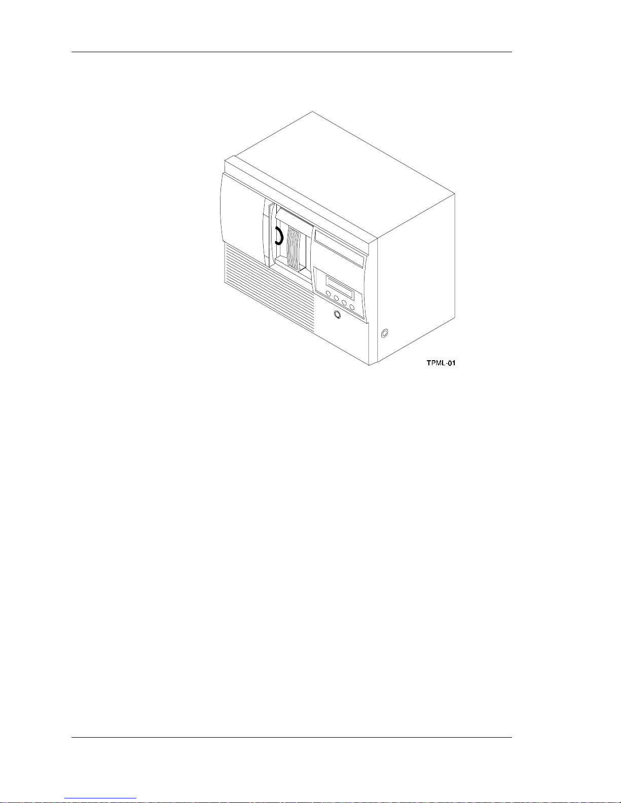
The SWXTL-BL tape mini-library (Figure 1-1) is a high performance, streaming
cartridge tape product designed for use on mid-range, and high-end computing systems.
As a mini-library that performs automatic tape operations, the SWXTL-BL contains a
high-capacity DLT tape drive and a five-cartridge, SCSI-2 medium changer device
(loader). With a typical load /unload cycle time of 20 seconds, the mini-library can
provide unattended back-up of 100 GB (compressed) in about 11 hours.
The half inch tape drive uses data compression and compaction. The drive features a
formatted capacity of 20 GB per cartridge (compressed) and a sustained user data transfer
rate of 2.5 Mbytes/second (assumes a 2:1 data compression factor). The drive has a dualchannel read/write head and Digital Lempel-Ziv (DLZ) high-efficiency data
compression. The drive tape mark directory maximizes data throughput and minimizes
data access time. The mini-library is housed in a tabletop enclosure and includes singleended or differential driver/receivers.
1
1.1.1 Fast Data Transfer Rate
Used for unattended backups or archiving, the mini-library allows you to back-up a high
data capacity at a high speed. When the SWXTL-BL operates in a non-compressed
mode, the mini-library drive has a maximum transfer rate of 1.25 Mbytes/second. When
operating in the compressed mode, the maximum transfer rate is 2.5 Mbytes/second write
and 3 Mbytes/second read.
1.1.2 High Capacity
The amount of data you can store on a tape cartridge can be 10 GB native capacity
(uncompressed), or if you select the compression mode, 20 GB compressed. Built-in data
compression increases the cartridge capacity and transfer rate 2 to 2.5 times.
The removable magazine in the mini-library has the capacity for five cartridges,
providing a total capacity of 100 Mbytes compressed, or 50 Mbytes uncompressed. You
can select compression on the mini-library front panel or through the host by using the
SCSI MODE SELECT command.
Tape Mini-Library User's Guide 1
Page 13
StorageWorks Tape Mini-Library
Figure 1-1. SWXTL-BL Tape Mini-Library
1.1.3 Compaction
The compaction feature of the mini-library tape drive helps you store data efficiently. A
read/write data cache of 2.0 Mbytes allows working space for the compaction, enabling
maximum use of available tape space.
1.1.4 Media Durability
The tape cartridge media, which provides superior media durability and data reliability,
can endure 500,000 passes and has a shelf life of 20 years.
1.1.5 Compatibility
Digital Equipment Corp. is committed to maintaining compatibility within the DLT
family of tape products. The SWXTL-BL, the second generation of the mini-library
family, offers users a smaller form factor and low cost alternative to the first generation
mini-library, the TZ877 (Digital Part No.). This device features an LCD display that
shows the operation of the mini-library with abbreviated messages.
The mini-library drive’s default density is 10 Gbytes (TZ87 format) compressed. The
mini-library drive can write 2.6 (TK85 format), 6.0 (TK86 format), and 10 Gbytes
(TZ87) tape formats for 100% interchange compatibility with earlier TZ8x drives. On a
write from BOT, the mini-library reformats the cartridge if a different density is selected.
2 Tape Mini-Library User's Guide
Page 14
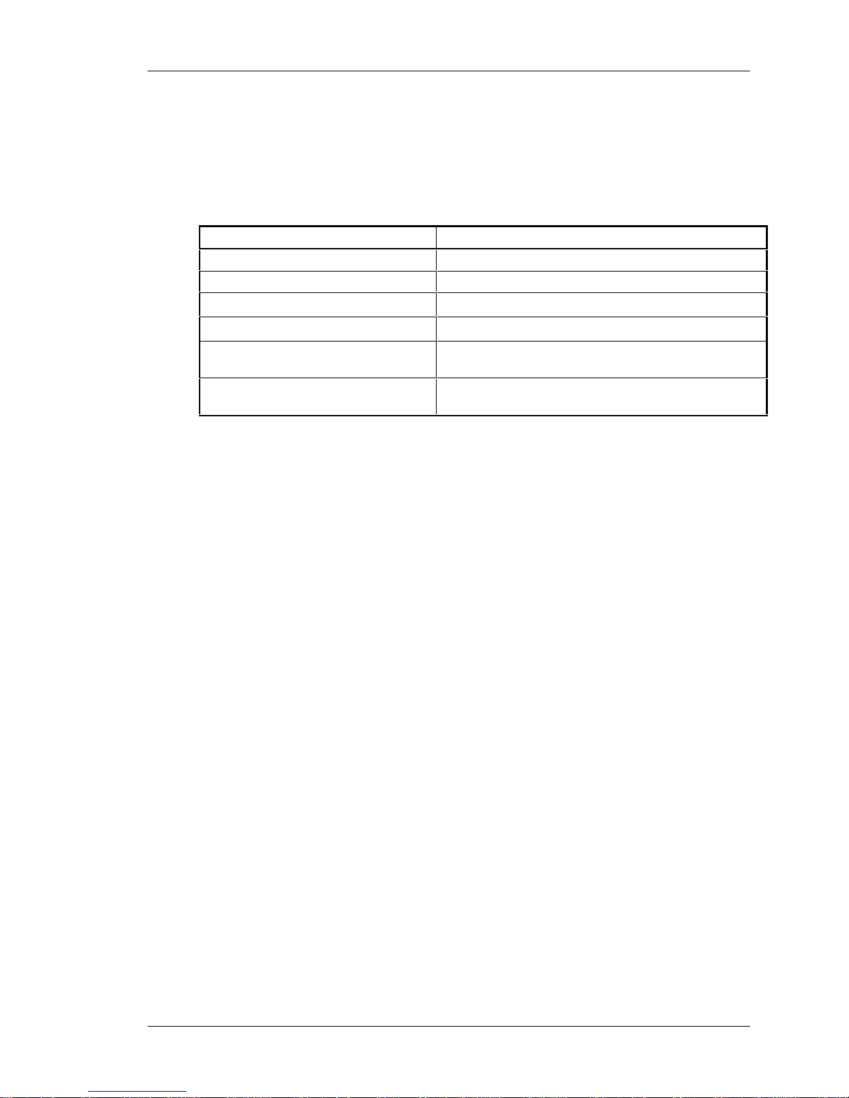
Older data cartridges can be loaded for read or read/write purposes into the SWXTL-BL
mini-library. Any cartridges recorded in 2.6, 6.0, 10, or 20 Gbyte (assumes 2:1 data
compression) can be read and written by the drive in the SWXTL-BL. Refer to Table 1-1
to determine cartridge compatibility with the SWXTL-BL mini-library.
Table 1-1. Read/Write Cartridge Compatibility with the SWXTL-BL Mini-Library
Cartridge Type/Format (Capacity) Read/Write Ability in the SWXTL-BL
CompacTape/TK50 (95 MBF) Read only
CompacTape III/TK70 (296 MBF) Read only
CompacTape III/TK85 (2.6 GBF)
CompacTape III/TK86 (6.0 GBF)
CompacTape III/TK87 (10 GBF or 20
GBF (assumes 2:1 compression)
CompacTape III/blank Read/write in 2.61, 6.01, 10, or 10C (20.0 GBF, assumes
1
Read/write, backward compatible with drive of selected density.
2
Recording format can be changed to 2.6, 6.0, 10, or 10C (compressed) GB mode on a write
from BOT (beginning of tape).
Chapter 1. Introduction
Read/write in 2.6 GB mode
Read/write in 6.0 GB mode
Read/write in 10 GB mode or 10C (compressed) GB
1, 2
mode
2:1 data compression) GB mode, as selected
.
1, 2
1, 2
The SWXTL-BL complies with the ANSI standard for SCSI-2. The tape media format
follows applicable ECMA approved and ANSI proposed standards.
1.1.6 Code Update Capability
The mini-library drive includes Flash EEPROM technology that allows easy on-site
installation of code updates from tape or over the SCSI bus.
1.1.7 Embedded Diagnostics
The mini-library has embedded power-on self-test (POST) and diagnostics that run
automatically when you turn on the power.
Tape Mini-Library User's Guide 3
Page 15
2
Installing and Operating the Mini-Library
This chapter describes the unpacking, installation, general configuration rules, POST test, and operation
for the tape drive mini-library. It also describes the tape cartridge and magazine, and when to insert a
cleaning tape cartridge.
2.1 Unpacking the Mini-Library
Before unpacking the mini-library, check the packing slip to ensure that the correct
equipment has been shipped. Inspect the shipping carton for damage (crushed corners,
punctures, etc.). The carton and packing material should be retained at the installation
site for reshipment.
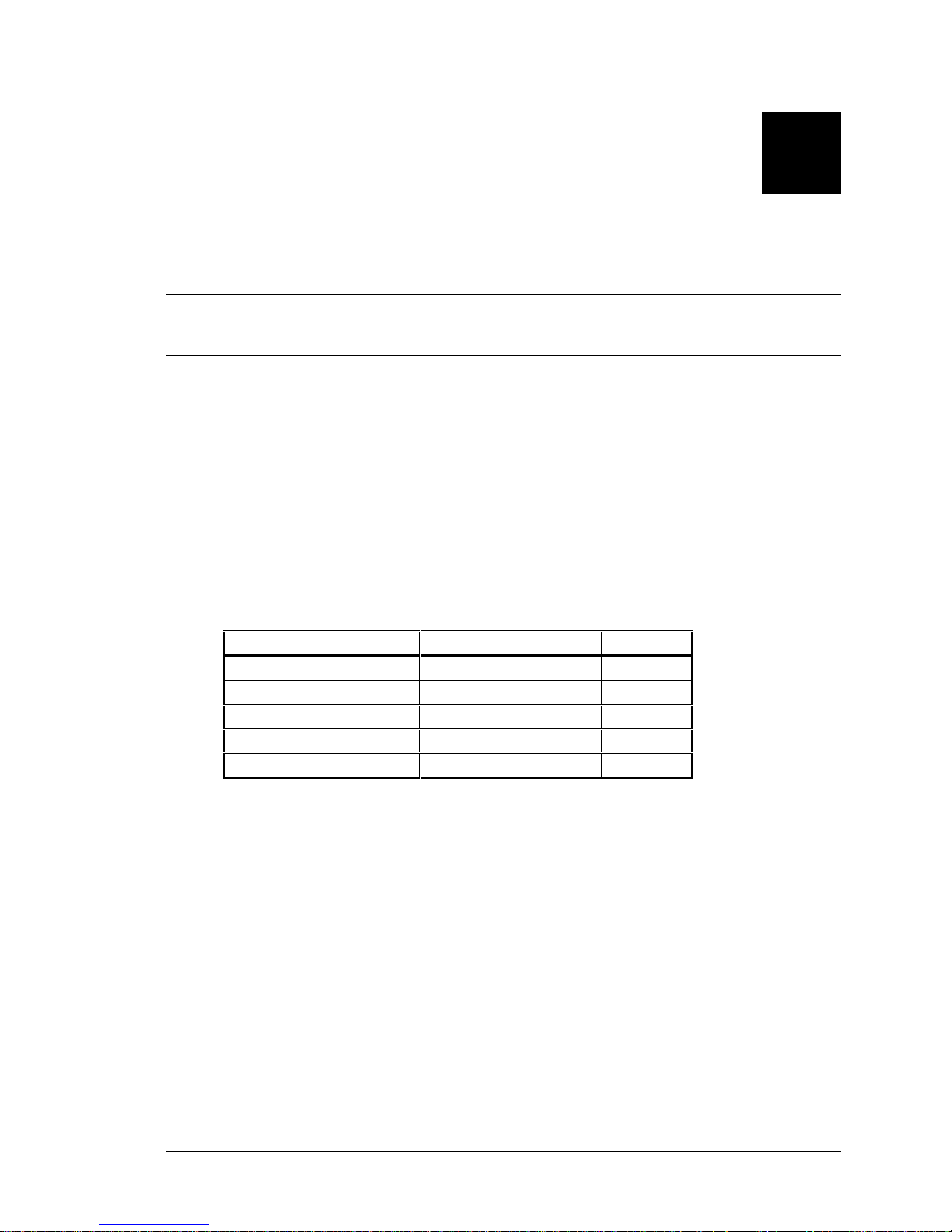
Unpack the mini-library and inventory the contents of the shipment. It should contain the
following components:
Table 2-1. Mini-Library Components
Item Digital Part Number Quantity
5-cartridge mini-library SWXTL-BL 1
Single tape cartridge unit TK85K-01 5
Head cleaning cartridge TK85-HC 1
SCSI terminator connector 12-30552-01 1
User’s guide EK-SM1TC-UG. A01 1
Also, confirm that you have received, either as a separate shipment or as part of the same
order (depending on your reseller), an appropriate SCSI-bus interface cable. Table 2-2
lists the SCSI cables corresponding to the type of SCSI interface controller mounted in
your computer system.
Tape Mini-Library User's Guide 2-1
Page 16

StorageWorks Tape Mini-Library
Digital SCSI Cable
Part Number
BC19J-1E (18 inches)
BC19J-06 (6.0 feet)
BC09D-03 (3.0 feet))
BC09D-06 (6.0 feet)
Table 2-2. Mini-Library SCSI Interface Cables
Application Drive-end
Connector
Low-Density toLow-Density Cable
Low-Density toHow-Density Cable
1
The 50-pin low-to low-density cable is compatible with most ISA-type SCSI-bus adapters.
2
The 50-pin high-dendsity is compatible with either of:
a. Most EISA-bus SCSI adapters.
b. Daisy-chain connection to DEC BA350 (Pedestal) or DEC BA353 (Desktop) SCSI storage expansion
cabinets.
Low-Density (50-pin) Low-Density (50-pin)
1
Low-Density (50-pin) How-Density (50-pin)
2
If you are connecting the mini-library to a fast, single-ended
SCSI bus, the interface cable cannot exceed three meters
(9.8 feet). If you are connecting the mini-library to a slow,
single-ended SCSI bus, the interface cable can be up to six
meters (19.7 feet) in length. Table 2-2 provides the partnumber identifications for ordering the appropriate cables.
Host-end
Connector
NOTE
2.2 Power and SCSI Bus Terminator Connections
NOTE
The purpose of the shipping screw is to secure the mini-library
elevator mechanism during shipment. Ensure the power
switch is set to
shipping screw. Also, always remove the tape cartridges from
the magazine before shipping the mini-library.
off
whenever loosening or tightening the
After unpacking the mini-library, be sure to:
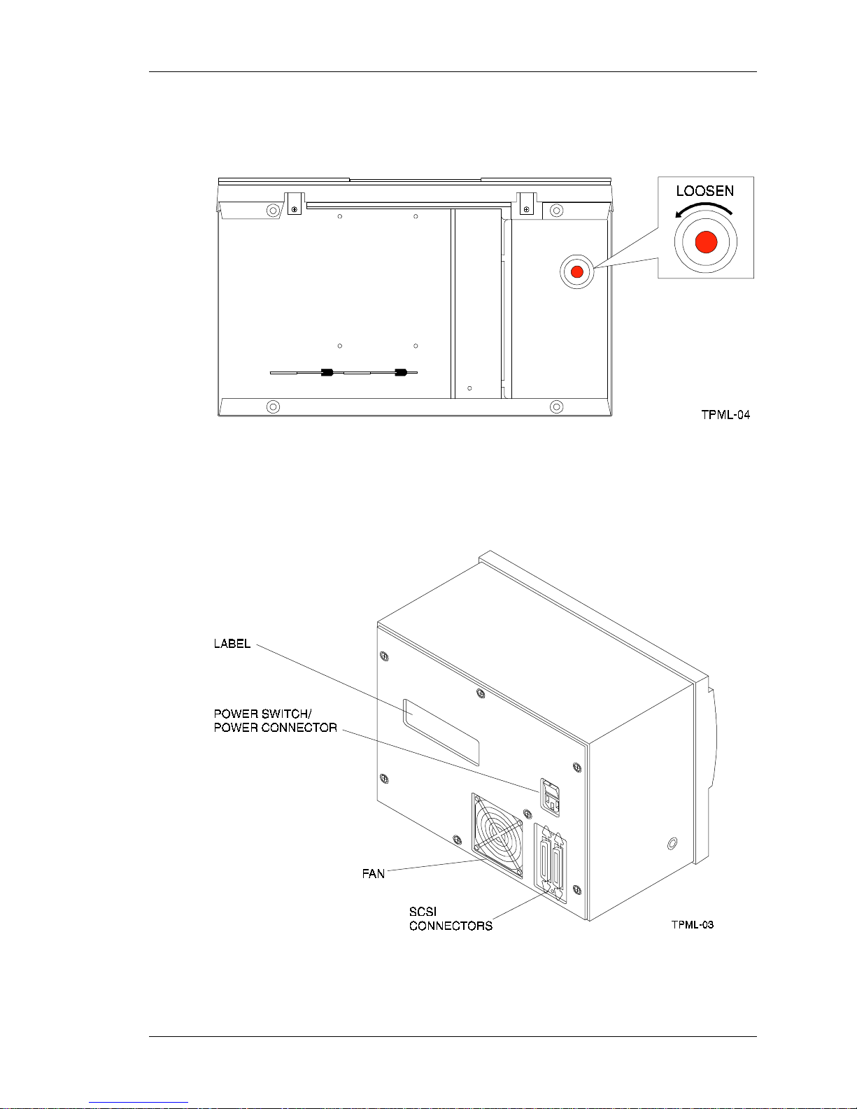
1. Loosen the shipping screw (Figure 2-1) by turning it counter clockwise before
turning on the power.
2. Ensure the power switch on the rear panel of the mini-library is set to off
(Figure 2-2).
3. Connect the power cord to the rear panel of the mini-library (Figure 2-2).
4. Connect the other end of the cord to a nearby ac outlet.
2-2 Tape Mini-Library User's Guide
Page 17
Chapter 2. Installing and Operating the Mini-Library
Figure 2-1. Shipping Screw under the Mini-Library
Figure 2-2. Mini-Library Rear Panel
Tape Mini-Library User's Guide 2-3
Page 18
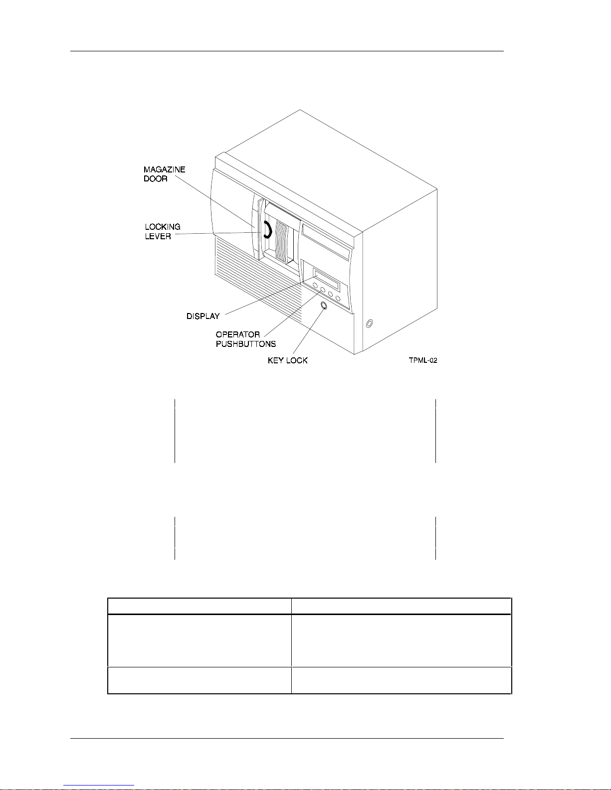
StorageWorks Tape Mini-Library
Figure 2-3. Mini-Library Front Panel
NOTE
The mini-library uses an auto-ranging power supply and will
accept a voltage range of 100 to 240 Vac and a frequency
range from 50 to 60 Hz.
5. Terminate the SCSI bus as described in Table 2-3 below.
NOTE
The SCSI bus must be terminated at both ends of the bus,
and at least one device must supply terminator power.
Table 2-3. Adding a SCSI Bus Terminator
If the mini-library is . . . Then . . .
The last or only device on the bus and you
are going to terminate the cables
externally
Not the last or only device on the SCSI
bus
1. Connect the SCSI terminator to the right SCSI
connector on the mini-library rear panel (Figure 2-2)
2. Snap the wire cable clamps into place to secure
the terminator.
Ensure to install the terminator at the end of the
SCSI bus.
2-4 Tape Mini-Library User's Guide
Page 19
Chapter 2. Installing and Operating the Mini-Library
6. Power on the mini-library by setting the power switch on the rear panel to on (1)
(Figure 2-2) and observe the LDR RDY (loader ready) message in the mini-library
display (Figure 2-3).
7. Unlock (enable) the operator control panel by turning the key in the keylock towards
the unlock icon on the mini-library (Figure 2-3).
8. To open the magazine door, press the Open push-button on the front panel
(Figure 2-4).
CAUTION
Never force or try to open the magazine door manually.
Always use the OPEN push-button on the operator control
panel which opens it electronically.
9. Turn the locking lever counter clockwise at the front of the mini-library (Figure 2-3)
to rotate the magazine locking mechanism. This allows you to remove the magazine
from the mini-library.
2.3 Introduction to the Mini-Library
The mini-library includes a DLT2000 tape drive, a media loader, and a five-cartridge
removable magazine. The same SCSI target controller controls the tape drive and the
media loader. If the controller detects the loader’s presence when the system is turned on,
the loader is presented as a SCSI-2 medium changer device on LUN (Logical Unit) 1. If
you issue the SCSI-2 medium changer commands to the SWXTL-BL:
• Random access is enabled to the media stored in the magazine slots
• Sequential access is disabled to the media supported automatically in the
auto-loading mode
If you do not issue the SCSI-2 medium changer commands, the default mode of
operation is sequential access to the media supported in the auto-loading mode. Auto
loading is implemented as a side effect of the SCSI UNLOAD command (Table 2-4).
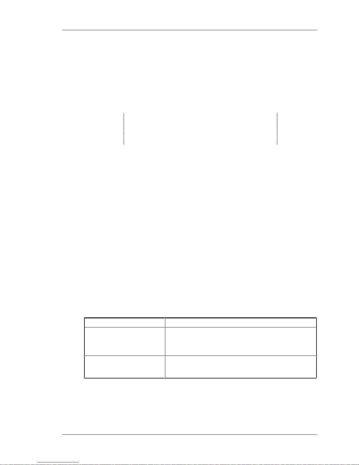
Table 2-4. SCSI-2 Command Conditions
IF. . . Then . . .
An unload is specified. After winding the tape back into the cartridge and moving the
cartridge from the drive to the magazine slot from which it
came, the cartridge in the next slot is moved from the
magazine into the drive and made ready.
The next slot is empty, or the
cartridge unloaded was for the
last slot in the magazine.
No cartridge is loaded into the drive.
Tape Mini-Library User's Guide 2-5
Page 20
StorageWorks Tape Mini-Library
2.4 Configuring and Installing the Mini-Library
This section describes the configuration rules and SCSI cable connections for the
mini-library.
NOTE
Unless otherwise specified, the mini-library is set to SCSI ID 0
at the library.
2.4.1 Configuration Guidelines
Your system uses the SCSI ID to identify, or address, the mini-library. Follow these
guidelines when configuring (Table 2-5) the mini-library for use on your system.
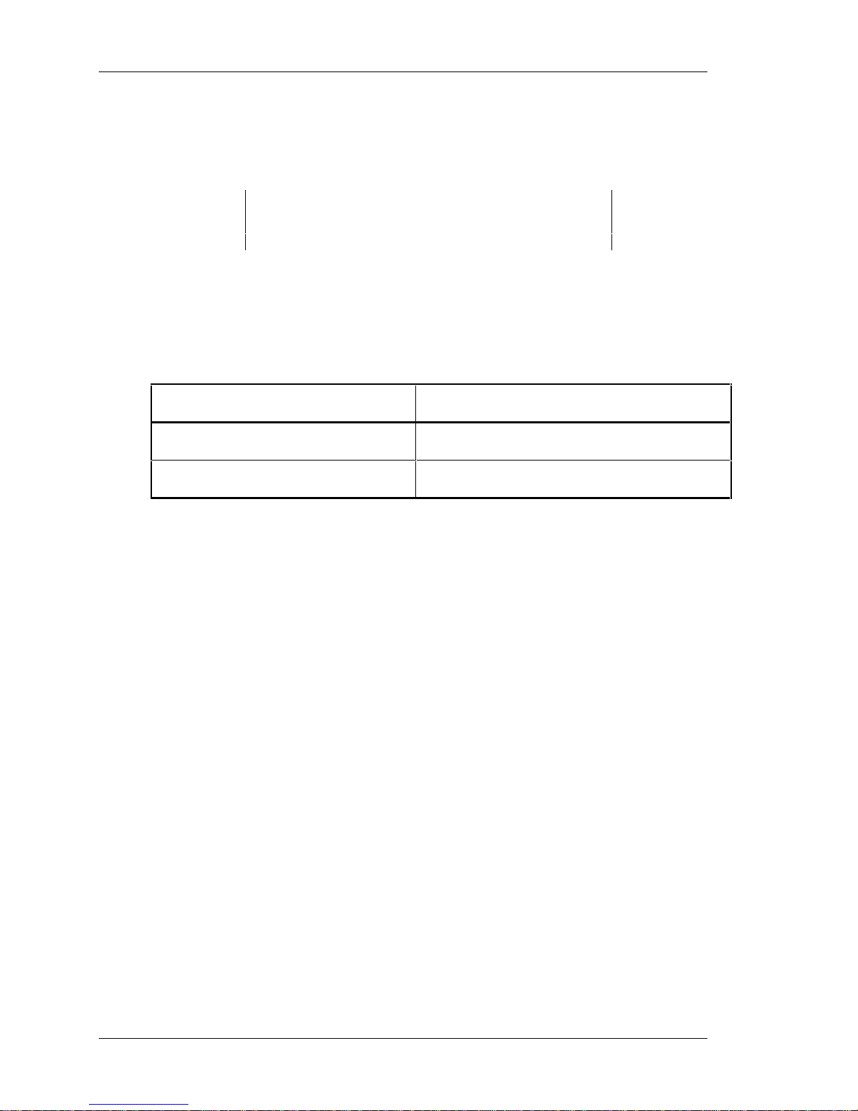
Table 2-5. Configuration Guidelines
If you are installing the mini-library as . ..Then . . .
The only SCSI device on the bus or one of
multiple SCSI devices on the bus.
The last or only device on the SCSI bus. You must terminate the bus by installing a
2.4.2 SCSI Cable Connection
Make the SCSI cable connection between the mini-library and the host system as
follows:
1. Ensure the power switch on the mini-library is turned off.
2. Connect one end of the SCSI cable to the left most connector on the rear panel of the
mini-library (see Figure 2-2) and snap the wire cable clamps into place to secure the
cable.
3. Connect the other end of the SCSI cable to the SCSI connector on the host system,
or for daisy-chained configurations, another SCSI device.
4. If the mini-library is the last SCSI device on the bus, ensure a SCSI bus terminator is
connected to the other SCSI connector on the rear panel of the mini-library.
2.5 POST Test
The POST (Power On Self Test) test runs automatically when the mini-library is turned
on. The POST test checks the integrity of the installation to ensure it is wired and
functioning properly. Perform the POST test as follows:
Be sure to use a SCSI ID that is unique from any
other device or system ID on the SCSI bus.
terminator.
1. Set the power switch on the rear panel of the mini-library to on (1).
2. Observe the sequence of events on the front panel display of the mini-library. They
should be as defined in Table 2-6.
3. If any of the display messages in the sequence of events did not occur, refer to
Table 2-7 for a POST test analysis.
2-6 Tape Mini-Library User's Guide
Page 21
Chapter 2. Installing and Operating the Mini-Library
Table 2-6. POST Display Messages
Event Display Message
1 LDR RST (loader reset)
2 LDR ACT (loader active)
3 Series of numbers displayed while mini-library elevator goes up and down (audible).
4 LDR RDY (loader ready)
Table 2-7. POST Test Analysis
If ... Then ...
All events in the Table occurred. POST succeeded. The mini-library is ready for operation.
All events in the Table did not
occur.
POST failed. You should see the display message LDR
RST (loader reset). Verify the following:
1. SCSI bus is terminated properly.
2. Set the mini-library power switch to off and then back
on. If the POST test fails again, call your service
representative.
2.6 Mini-Library Operator Control Panel
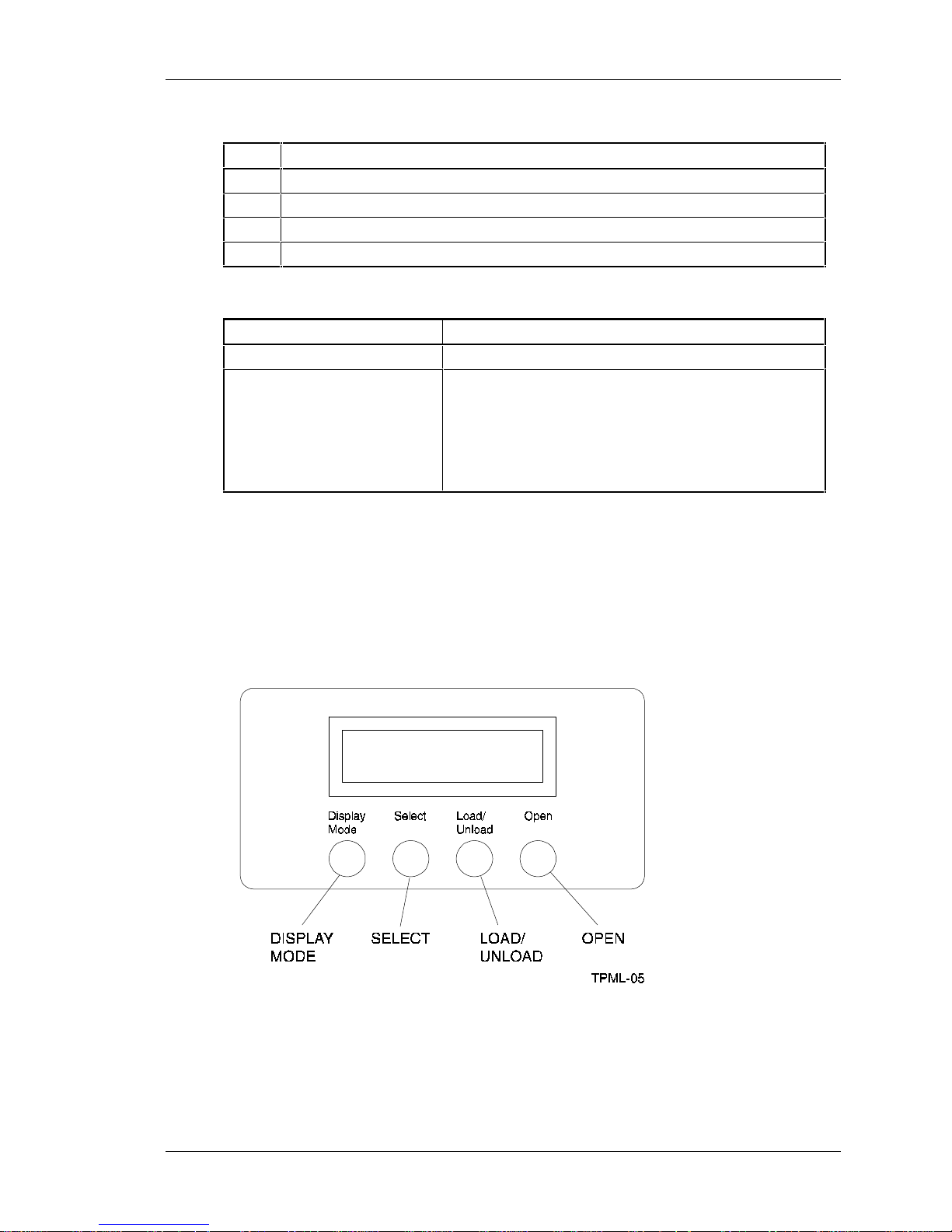
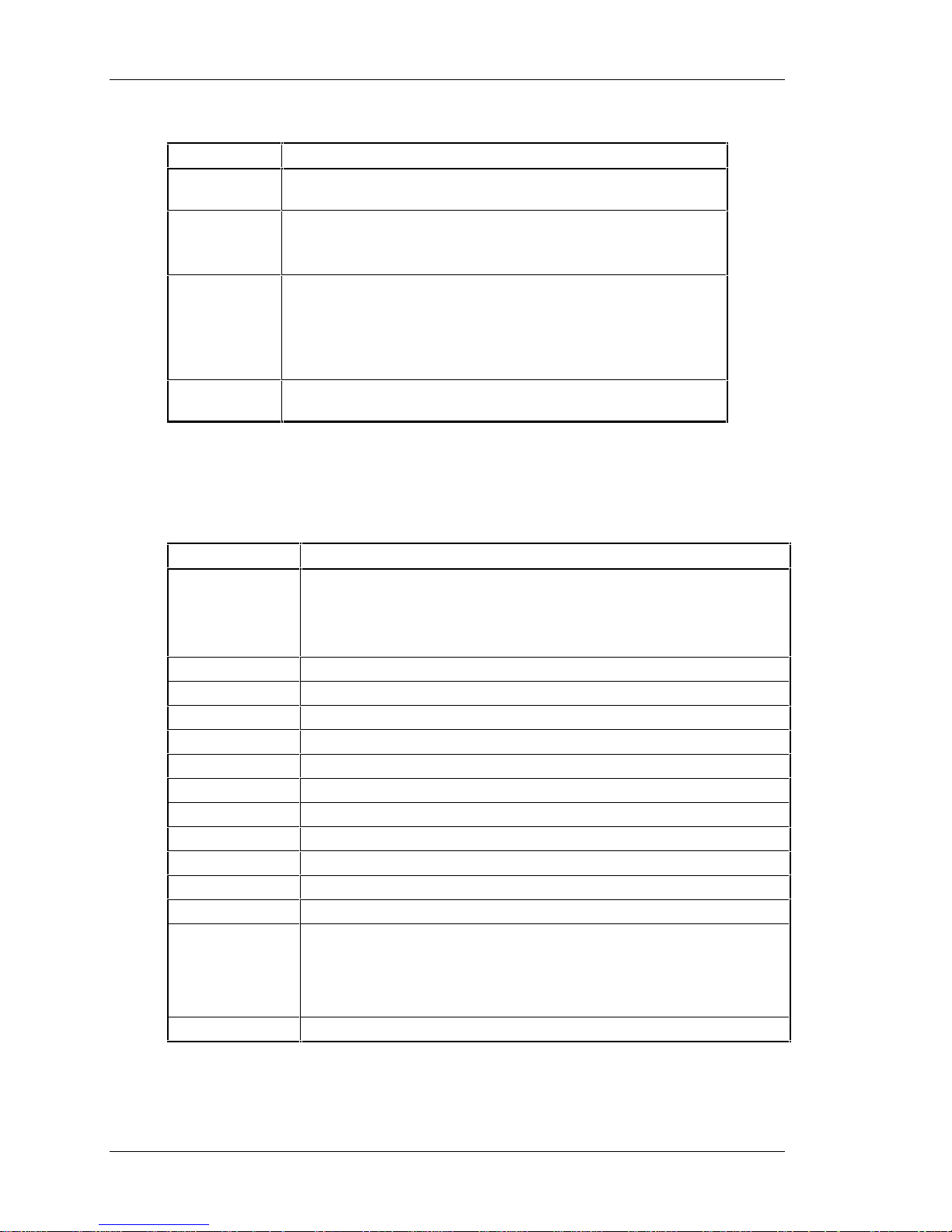
The operator control panel contains four push-button switches as shown in Figure 2-4.
Table 2-8 identifies the switches and defines their functions.
Figure 2-4. Mini-Library Operator Control Panel
Tape Mini-Library User's Guide 2-7
Page 22
StorageWorks Tape Mini-Library
Table 2-8. Operator Control Panel Functions
Push-button Function
Display Mode Puts the mini-library in the Normal, Density Select, or SCSI ID
Select mode.
Select • Selects SCSI ID and density.
• Moves, in increments, the current slot number on the display to
the next slot number.
Load/Unload • Loads the cartridge currently selected into the tape drive.
• Unloads the cartridge currently in the drive.
• Resets the mini-library if a loader error has occurred. When the
ERR LDR message displays, press the Load/Unload button to
reset the mini-library
Open • Opens the magazine door allowing access to the magazine for
loading and unloading cartridges.
Table 2-9 lists and describes the possible display messages which may be seen on the
operator control panel during normal operation.
Table 2-9. Operator Control Panel Display Messages
Display Message Description
WP The cartridge in the drive is write-protected by one of the following:
• The write-protect switch on the cartridge is set to the write protect
position
• Host software write-protect qualifiers
DRIVE ACT Tape is reading or writing.
DRIVE RDY A cartridge is in the drive and the tape is not moving.
DRIVE REW Tape is rewinding.
HC The read/write head needs cleaning.
LDR RDY Power is on and no cartridge is in drive.
LDR ACT Loader is moving a cartridge.
ERR MAG The status of cartridges reported by the loader and drive is inconsistent.
ERR LDR A loader transfer assembly error has occurred.
ERR DRV A drive error has occurred.
ERR CTL A controller error has occurred.
ERR UNK An error of unknown origin has occurred.
SLOT 0
SLOT 1
SLOT 2
SLOT 3
SLOT 4
DNS SEL The mini-library is in the Density Select mode.
The current slot containing the cartridge. Each current slot number flashes
on the display when its corresponding cartridge moves to or from the drive.
Also used with the ERR MAG or ERR LDR message to show error type.
2-8 Tape Mini-Library User's Guide
Page 23

Chapter 2. Installing and Operating the Mini-Library
Table 2-9. Operator Control Panel Display Messages (Con’t)
OVR Tape drive activity is as follows:
On
•
•
•
2.6 Tape drive activity is as follows:
•
•
6 Tape drive activity is as follows:
•
•
10 Tape drive activity is as follows:
•
•
10C Tape drive activity is as follows:
•
•
continuously indicates “density” on front panel
Off
(default) indicates “density” selected automatically
Flashing
On
Flashing
selected this density for a write from BOT
On
Flashing
selected this density for a write from BOT
On
Flashing
selected this density for a write from BOT
On
Off
indicates mini-library is in “density selection” mode
continuously indicates tape is recorded in 2.6 format
indicates the tape is recorded in another density. You have
continuously indicates tape is recorded in 6 GB format
indicates the tape is recorded in another density. You have
continuously indicates tape is recorded in 10 GB format
indicates the tape is recorded in another density. You have
indicates Compression mode enabled (10 GB density only)
indicates Compression mode disabled
2.7 Key Lock
The key lock on the front panel of the mini-library (Figure 2-3) enables the operator
control panel. The key lock prevents unauthorized removal of the magazine or cartridges,
providing a measure of data security. To unlock (or enable) the operator control panel,
insert and turn the key toward the opened lock icon next to the key lock (Figure 2-3). To
lock (or disable) the operator control panel, insert and turn the key to the locked icon
next to the key lock.
CAUTION
Never force or try to open the magazine door manually.
Always use the OPEN push-button on the operator control
panel which opens it electronically.
2.8 Operator Control Panel Locked (Disabled)
When the magazine is inserted into the mini-library and the door is closed, the elevator
scans the magazine. The first cartridge in the magazine automatically loads into the
drive. When you are copying data to the tape, mini-library operations stop if one of the
following conditions occurs:
• The storage capacity of the last tape cartridge is exceeded
• No tape cartridge is in the next sequential slot in the magazine
• The operator control panel pushbuttons are disabled
Tape Mini-Library User's Guide 2-9
Page 24

StorageWorks Tape Mini-Library
2.9 Operator Control Panel Unlocked (Enabled)
The operator control panel push-buttons are unlocked or enabled, it allows the operator
intervene. This enables the mini-library to load or unload cartridges as needed during
backup procedures. When you are copying data to the tape, operations stop if one of the
following conditions occurs:
• The storage capacity of the last tape cartridge is exceeded
• No tape cartridge is in the next sequential slot in the magazine
2.10 Setting the SCSI ID of the Mini-Library
To set the SCSI ID of the mini-library, you must first choose an unused SCSI ID
between 0 and 7. Then set the SCSI ID from the operator control panel as follows:
1. Press and hold the Display Mode push-button (about five seconds) until the
SCSI ID SEL message is displayed including the factory set SCSI ID.
Example:
SCSI ID SEL
SCSI ID 0
2. Press the Select push-button with quick presses until you see the ID number you
want in the display (Figure 2-4).
3. Press the Display Mode push-button again. When the display message LDR RDY
appears, the mini-library drive cannot recognize the SCSI ID yet.
4. Issue a “bus reset” or turn the mini-library power off and on again for the drive to
recognize the new SCSI ID.
2.11 Select Density
This section describes the mini-library’s density select feature. You can select density by
using any of the following steps:
1. On a Write from BOT, the tape density is selected by one of the following:
• Front panel Density Select mode
• Programmable host selection via your operating system
NOTE
You can do a front panel density selection at any time, but the
selection takes effect only on the next write from BOT.
• Native default density 10 GB and compress (assuming you did not use the Select
Mode or the host selection)
2. On all read operations and all write append operations, the recorded density is the
density to be used.
2-10 Tape Mini-Library User's Guide
Page 25

Chapter 2. Installing and Operating the Mini-Library
CAUTION
Executing any “Write from BOT” operations destroys existing
data on tape.
2.11.1 Front Panel Density Select Mode
To select density via the front panel:
1. If a tape is loaded in the drive, the display shows the tape’s pre-recorded density.
2. You can use the mini-library operator control panel at various times, not just after
loading a tape. Density selection is inactive until the write from BOT command is
issued. The controller remembers the density selection state until you do one of the
following:
• Change the density selection
• Press the Open push-button to open the door
3. Enter the Density Select mode by pressing the Display Mode push-button and then
the Select push-button on the operator control panel. Using the Density Select mode
always overrides a host selection.
Example:
If you have loaded a tape with a pre-recorded density of 2.6 and you use the
Density Select mode to select a density of 10:
Before a “Write from BOT” occurs, you should see the 2.6 continuously displayed, and
the 10 and OVR flashing in the display, as shown:
LDR RDY
2.6 10 OVR
After a “Write from BOT” occurs, you should see the selected density of 10 and the
OVR should be continuously displayed as shown below
LDR RDY
10 OVR
Table 2-10 shows the results.
Tape Mini-Library User's Guide 2-11
Page 26

StorageWorks Tape Mini-Library
Table 2-10. Results of not Using or Using Density Select Mode
If . . . Then . . .
You did not use the Density Select
mode
You used the Density Select mode and
the actual tape density is the same as
the density you selected.
You used the Density Select mode and
the actual tape density differs from the
density you selected.
The display shows the actual density when the tape
is reading and writing.
The display shows the actual density and OVR on
continuously.
On operation before “Write from BOT”, the display
shows:
• Actual tape density on continuously
• Selected density flashing
• OVR flashing
On operation after “Write from BOT”, the display
shows:
• Selected density on continuously
• OVR on continuously
2.11.2 Programmable Host Selection via Your Operating System
To select density via the SCSI bus:
1. Do a SCSI MODE SELECT with the density you want. For more details, see the
DLT2000 Series Magnetic Tape Product Manual, (EK-TH4XX-IM).
2. Write data to the tape from BOT.
2.11.3 Native Default Density 10 GB and Compress
If you did not use the front panel Density Select mode or Programmable Host
selection, the selection becomes the native default density of 10 GB and Compress.
2.12 Default Operating Modes
The mini-library operates in four modes: Normal, Density Select, SCSI ID Select, and
Code Select.
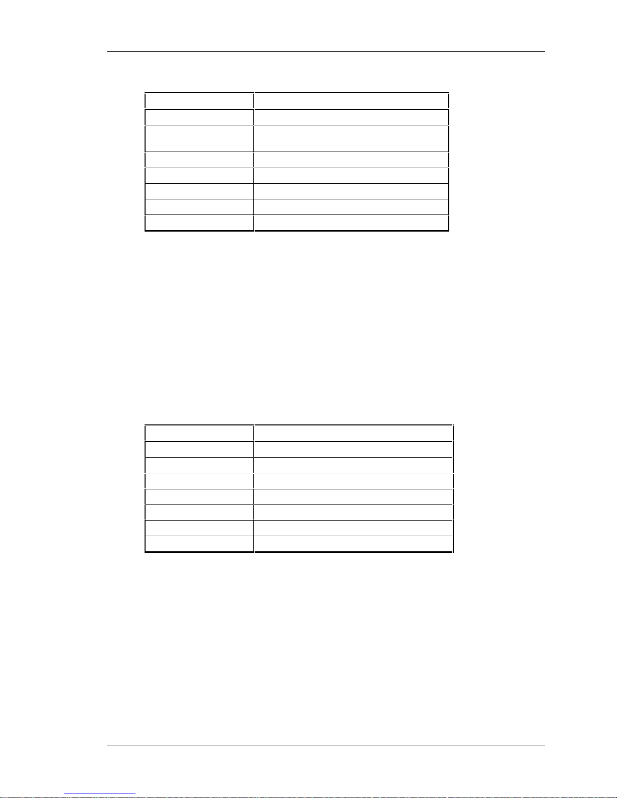
2.12.1 Normal Mode
The Normal mode is used by default after you turn on or reset the mini-library. The
information displayed during this mode depends on the state of the mini-library as
follows:
2-12 Tape Mini-Library User's Guide
Page 27
Chapter 2. Installing and Operating the Mini-Library
Table 2-11. Normal Mode Definitions
If the display says . . . It means the . . .
LDR ACT Loader is active
LDR RDY Loader is inactive and no cartridge is in
drive.
DRV RDY Drive is ready
DRV ACT Drive is active
DRV REW Tape is rewinding
HC Use cleaning tape
WP Drive is in write-protect status
The push-button switch functions while in the Normal mode operates as follows:
• When you press and release the Display Mode push-button, the mini-library enters
the Density Select mode of operation
• When you press and hold the Display Mode push-button for about 5 seconds, the
mini-library enters the SCSI ID Select mode of operation
2.12.2 Density Select Mode
The Density Select mode allows you to select the drive density. The information
displayed during this mode depends on the state of the mini-library as follows:
Table 2-12. Density Select Definitions
If the display says . . . It means the . . .
DNS SEL Mini-library is in the Density Select mode.
OVR Front panel selection overrides host selection
DRV RDY Drive is ready
DRV ACT Drive is active
DRV REW Tape is rewinding
HC Use cleaning tape
WP Drive is in write-protect status
When you press and release the Display Mode push-button switch once in the Density
Select mode, the mini-library enters the Normal mode of operation.
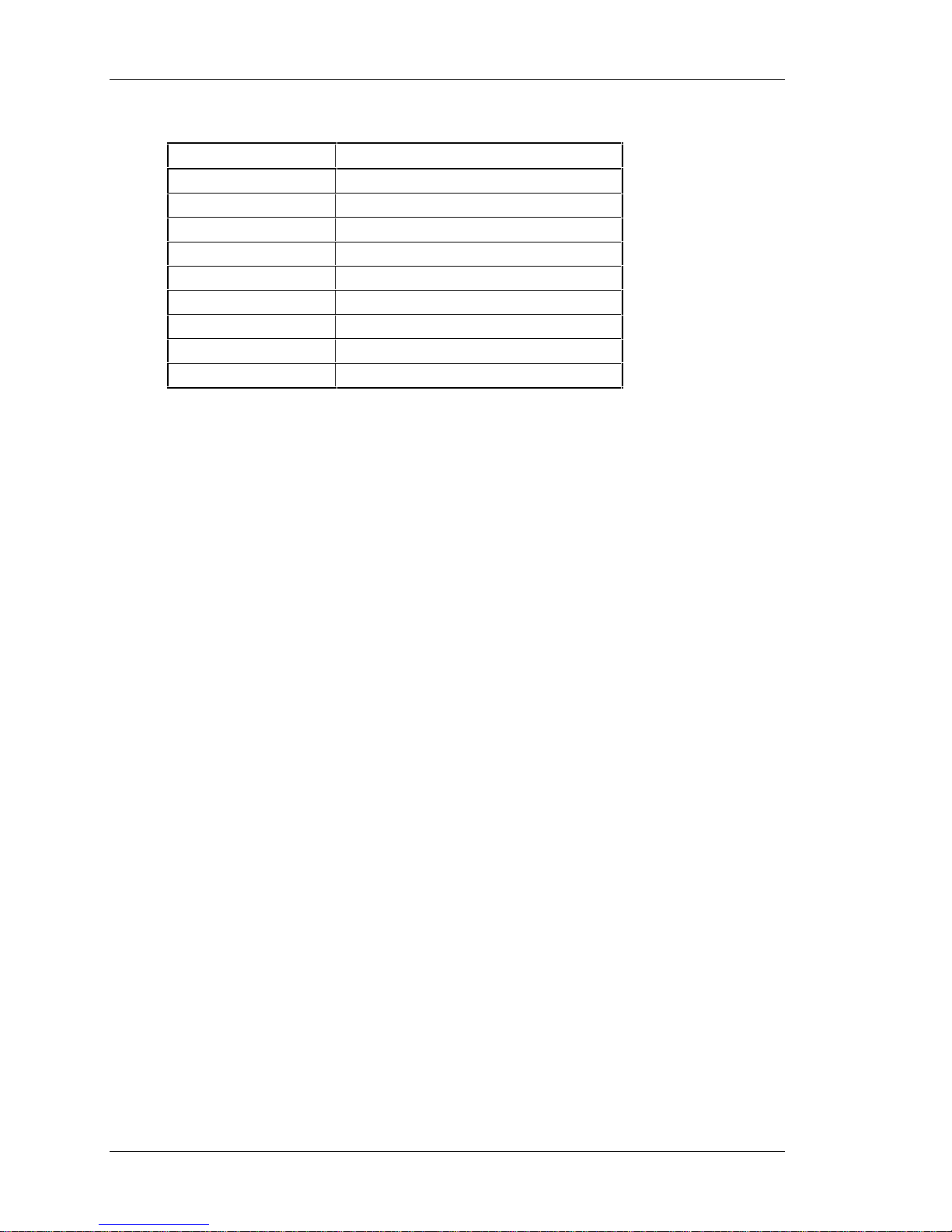
2.12.3 SCSI ID Select Mode
The SCSI ID Select mode allows you to select the SCSI ID for the tape drive and to
enter the Code Update mode of operation. If you turn off and turn on the power again or
reset the mini-library, the SCSI ID you chose reappears after being stored. The
information displayed during this mode depends on the state of the mini-library as
follows:
Tape Mini-Library User's Guide 2-13
Page 28
StorageWorks Tape Mini-Library
Table 2-13. SCSI ID Select Mode
If the display says . . . It means the . . .
SCSI ID SEL Mini-library is in the SCSI ID Select mode.
SCSI ID 0 SCSI ID is set to 0
SCSI ID 1 SCSI ID is set to 1
SCSI ID 2 SCSI ID is set to 2
SCSI ID 3 SCSI ID is set to 3
SCSI ID 4 SCSI ID is set to 4
SCSI ID 5 SCSI ID is set to 5
SCSI ID 6 SCSI ID is set to 6
SCSI ID 7 SCSI ID is set to 7
If you press the Select push-button while in the SCSI ID Select mode, the stored SCSI
ID you chose moves by one increment. If you press the Select push-button when the
stored SCSI ID is 7, then the SCSI ID moves to 0.
If you press and release the Display Mode push-button in the Density Select mode, the
mini-library enters the Normal mode of operation.
2.12.4 Code Update Mode
Refer to Chapter 3 to place the mini-library in the Code Update mode.
2.13 Tape Cartridge Description
The tape cartridge is a four-inch, gray, plastic cartridge containing 1,100 feet of 1/2 inch
magnetic metal particle tape.
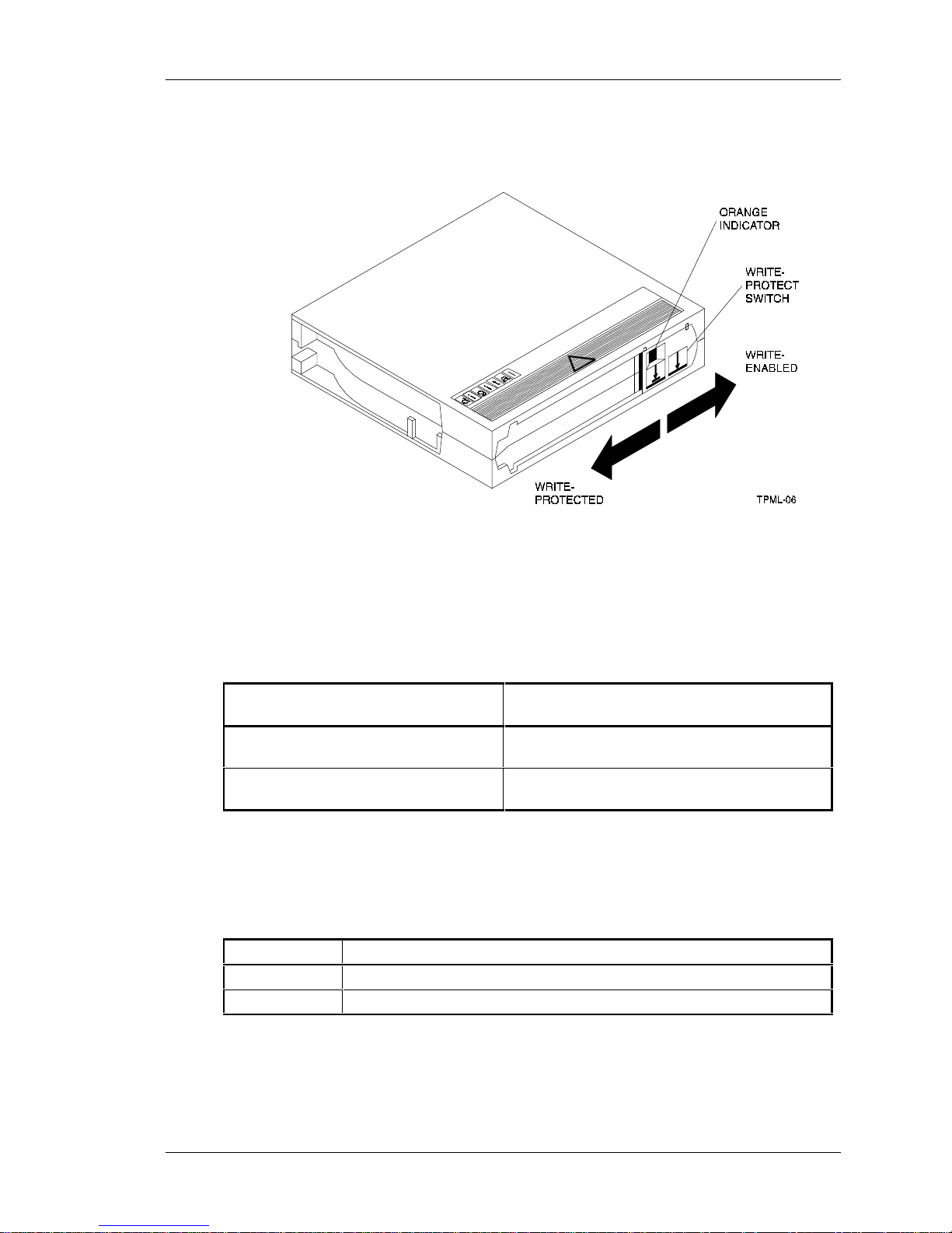
2.13.1 Cartridge Write-Protect Switch
The tape cartridge has a write-protect switch to prevent accidental erasure of data. Before
loading the tape cartridge into the drive, position the write-protect switch on the front of
the cartridge (Figure 2-5). When the switch is moved to the left, the cartridge is writeprotected. When the switch is moved to the right, the cartridge is write enabled.
When you slide the switch to the left, the small orange rectangle is visible, which means
data cannot be written to the tape. The arrow (beneath the orange rectangle and over the
two lines on the write-protect switch) indicates that data cannot be written to the tape.
On the right side of the write-protect switch is another symbol: an arrow over one line.
This symbol indicates that if you slide the write-protect switch to the right, data can be
written to the tape.
2-14 Tape Mini-Library User's Guide
Page 29
Chapter 2. Installing and Operating the Mini-Library
Figure 2-5 Tape Cartridge Write-Protect Switch
2.13.2 Data Protection
If you move the cartridge write-protect switch to the left, and then load the tape, the WP
(write protect) message displays. Table 2-14 describes what happens to data protection
when you move the write-protect switch before loading the cartridge.
Table 2-14 Before Loading the Cartridge
If you move the write-protect switch . ..Then . . .
To the left, the tape is write-protected,
with the orange indicator showing
To the right, the tape is write-enabled You cannot write data to the tape (if it is not
You cannot write data to the tape.
software write-protected).
2.13.3 Ordering Cartridges
Table 2-15 lists the cartridges with order numbers for the SWXTL-BL mini-library.
Table 2-15. Cartridge Order Numbers
Order Number Description
TK85-01 CompacTape III cartridge. Five cartridges shipped with the mini-library.
TK85-HC CleaningTape III cartridge. One cartridge ships with the mini-library.
Tape Mini-Library User's Guide 2-15
Page 30
StorageWorks Tape Mini-Library
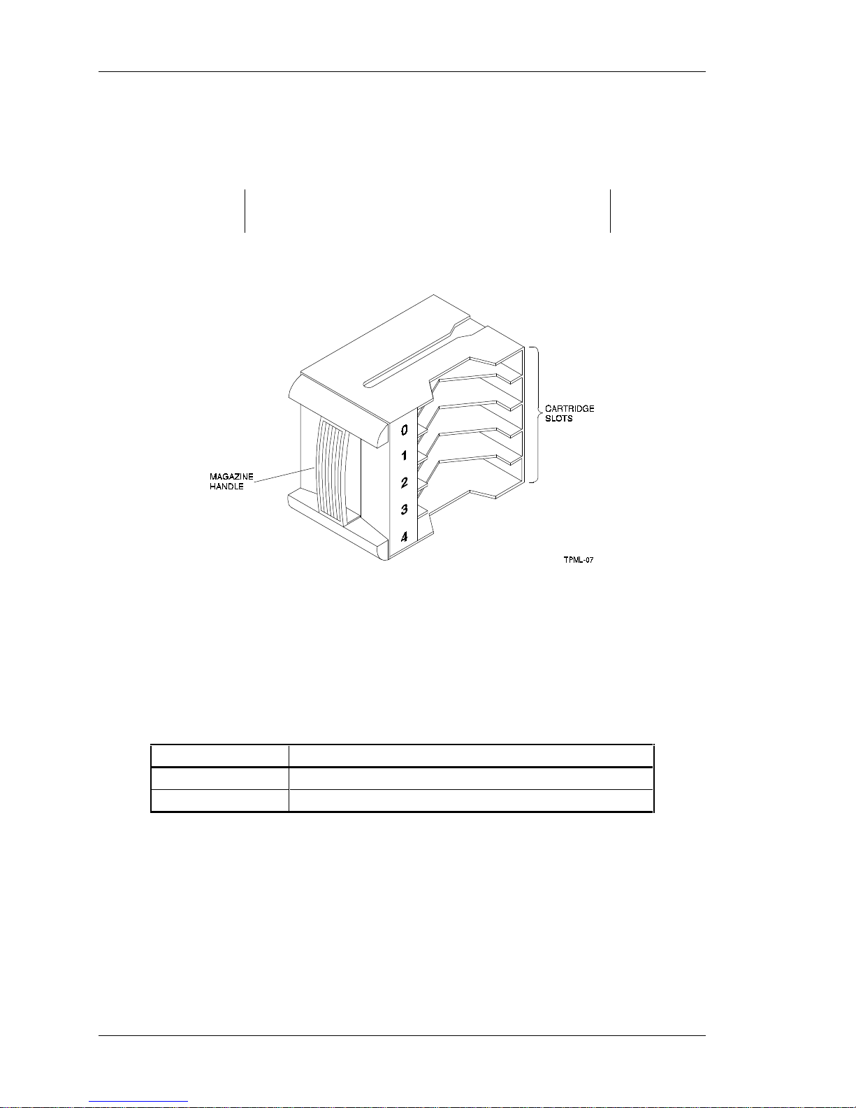
2.14 Description of the Magazine
The front of the magazine has numbers 0 through 4 marked, indicating each slot number
(Figure 2-6).
Insert and remove all cartridges at the front of the magazine.
Figure 2-6. SWXTL-BL Magazine
NOTE
2.14.1 Inserting a Cartridge into the Front of the Magazine
Before you insert a cartridge:
1. Grasp the cartridge with the write-protect switch facing you.
2. Set the cartridge’s write-protect switch to the desired position as follows:
Table 2-16. Setting the Write-Protect Switch
If you want to . . . Then . . .
Write to the tape Slide the switch to the right (orange indicator is not visible).
Write-protect the tape Slide the switch to the left (orange indicator is visible).
To insert a cartridge into the magazine (Figure 2-7):
1. Place the magazine on a flat surface with the slots facing you. Each slot is numbered
to ensure you are inserting the cartridge correctly into the front of the magazine.
Usually, cartridges are inserted into consecutive slots.
2. Insert the cartridge by pushing it into the slot until you hear a click.
3. Notice a small metal tab.
4. This holds the cartridge in place.
2-16 Tape Mini-Library User's Guide
Page 31
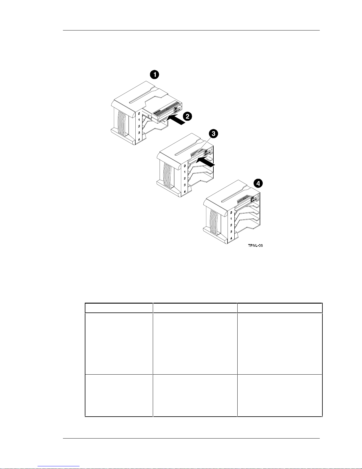
Chapter 2. Installing and Operating the Mini-Library
Figure 2-7. Inserting a Cartridge into the Magazine.
2.15 When to Use the Cleaning Tape Cartridge
Use Table 2-17 to determine when to use the cleaning cartridge.
Table 2-17. When to Use the Cleaning Cartridge
If . . . It means . . . And you should . . .
1. The HC message
displays.
2. A data cartridge
causes the HC message
to display frequently.
The drive head needs cleaning
or the tape is bad. (See item 3)
The data cartridge may be
damaged.
Use the cleaning cartridge.
Follow the instructions in this
chapter to insert a cartridge into
the magazine and load into the
drive. When cleaning is
complete, the cleaning cartridge
unloads from the drive and
returns to the magazine. The
LDR RDY message displays.
Backup this data on another
cartridge. Discard the old
cartridge, which may be
damaged. A damaged cartridge
may cause unnecessary use of
the cleaning cartridge.
Tape Mini-Library User's Guide 2-17
Page 32
StorageWorks Tape Mini-Library
Table 2-17. When to Use the Cleaning Cartridge (Con’t)
3. The HC message still
displays after you clean
the drive head.
4. The HC message
displays after you load
the cleaning cartridge.
The cleaning cartridge expires after approximately 20 uses.
Your data cartridge may be
causing the problem.
Cleaning has not been done and
the cartridge is expired.
NOTE
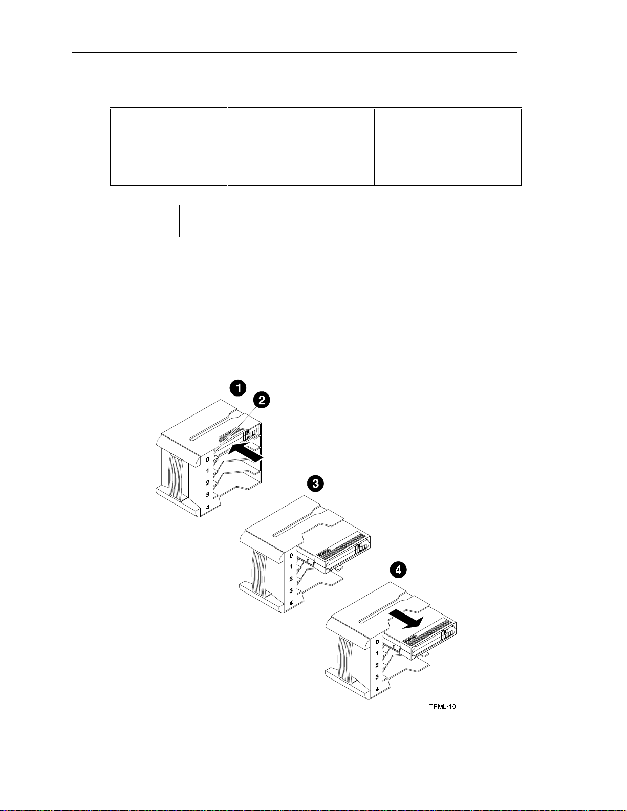
2.16 Removing a Cartridge from the Magazine
To remove a cartridge from the magazine (Figure 2-8) press in on the cartridge where
you can see the metal tab next to the slot number until it stops and you hear a click, then
release. The slot has a spring-release action causing the cartridge to snap out.
Figure 2-8. Removing a Cartridge from the Magazine
Try another cartridge.
Replace the cleaning cartridge.
2-18 Tape Mini-Library User's Guide
Page 33

Chapter 2. Installing and Operating the Mini-Library
CAUTION
To prevent cartridge jams in the mini-library, never apply
labels to the top or bottom of tape cartridges. Always use the
space on the front of the cartridge for labels.
2.17 Removing the Magazine from the Mini-Library
To remove the magazine from the mini-library, first ensure the operator control panel is
enabled or unlocked via the key lock (Figure 2-3). Then perform the following:
1. If a tape is loaded in the drive, press the Load/Unload push-button to unload the
tape from the drive and load into the magazine. Press the Open push-button to open
the door of the mini-library.
2. Slide the door all the way to the left.
3. Grasp the magazine’s handle and pull the magazine out of the mini-library.
2.18 Installing the Magazine into the Mini-Library
CAUTION
Do not force the magazine door open manually. Always use
the operator control panel Open push-button, which opens the
door electronically.
To install the magazine, perform the following:
1. Ensure the door has moved all the way to the left.
2. Slide the magazine into the mini-library doorway while holding the magazine by the
handle (Figure 2-6). Since the magazine is slotted, you can insert the magazine in the
correct orientation only.
3. Slide the door to the right until it closes.
2.19 Selecting a Cartridge from the Magazine
After a successful initialization, the mini-library automatically selects the first slot
containing a cartridge and the Select push-button is enabled. To select a cartridge, press
the Select push-button to advance to the next slot containing a cartridge.
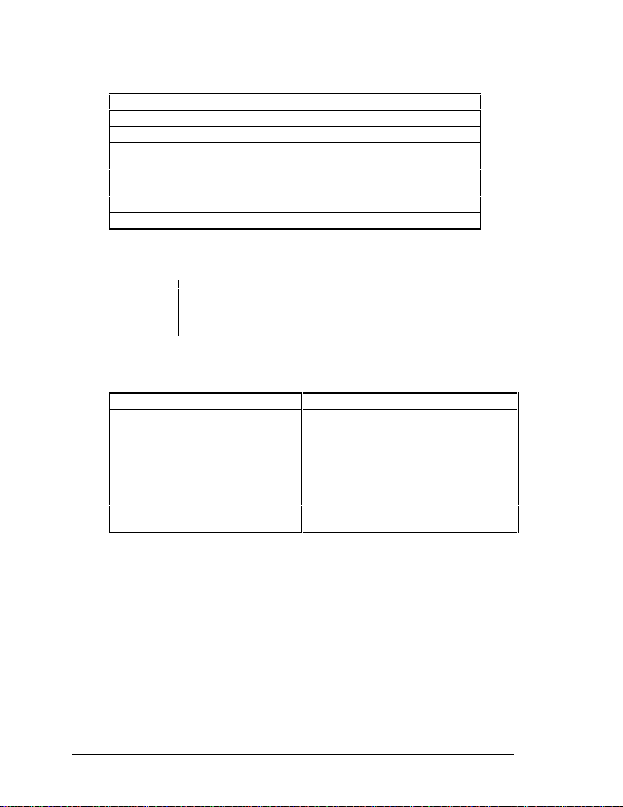
2.20 Loading the Cartridge
To load the cartridge from the magazine into the drive, press the Load/Unload pushbutton and observe the loading sequence as described in Table 2-18.
Tape Mini-Library User's Guide 2-19
Page 34
StorageWorks Tape Mini-Library
Table 2-18. Cartridge Loading Sequence
Stage Event
1 The elevator moves to the selected slot.
2 The cartridge is then removed from the magazine and placed in the elevator.
3 The elevator moves to the drive position and inserts the cartridge into the
drive.
4 The display reads LDR ACT until the tape has loaded to the beginning of the
tape (BOT).
5 After the cartridge is loaded into the drive, the display reads DRV ACT.
6 After the cartridge is fully loaded and at BOT, the display reads DRV RDY.
2.21 Unloading the Cartridge
Do not press the Load/Unload push-button until backup or
other tape operations are stopped at the terminal. Doing so
can result in operation failure and drive unavailability.
CAUTION
Table 2-19. Unloading the Cartridge
If . . . Then . . .
You want to unload the cartridge from the
drive.
The ERR LDR message displays, showing
a malfunction.
2.22 Opening the Magazine Door
The Open push-button opens the magazine door for insertion or removal of the
magazine. The push-button is disabled when the key lock is in the locked or disabled
position. Table 2-20 describes magazine door operations.
Press the Load/Unload push-button and observe
the following:
• The DRV REW message displays
• The cartridge unloads from the drive and the
display reads LDR ACT
• When the cartridge returns to the magazine,
the display reads LDR RDY
Press the Load/Unload push-button to reset the
mini-library and try to clear the error.
2-20 Tape Mini-Library User's Guide
Page 35
Chapter 2. Installing and Operating the Mini-Library
Table 2-20. Opening the Magazine Door
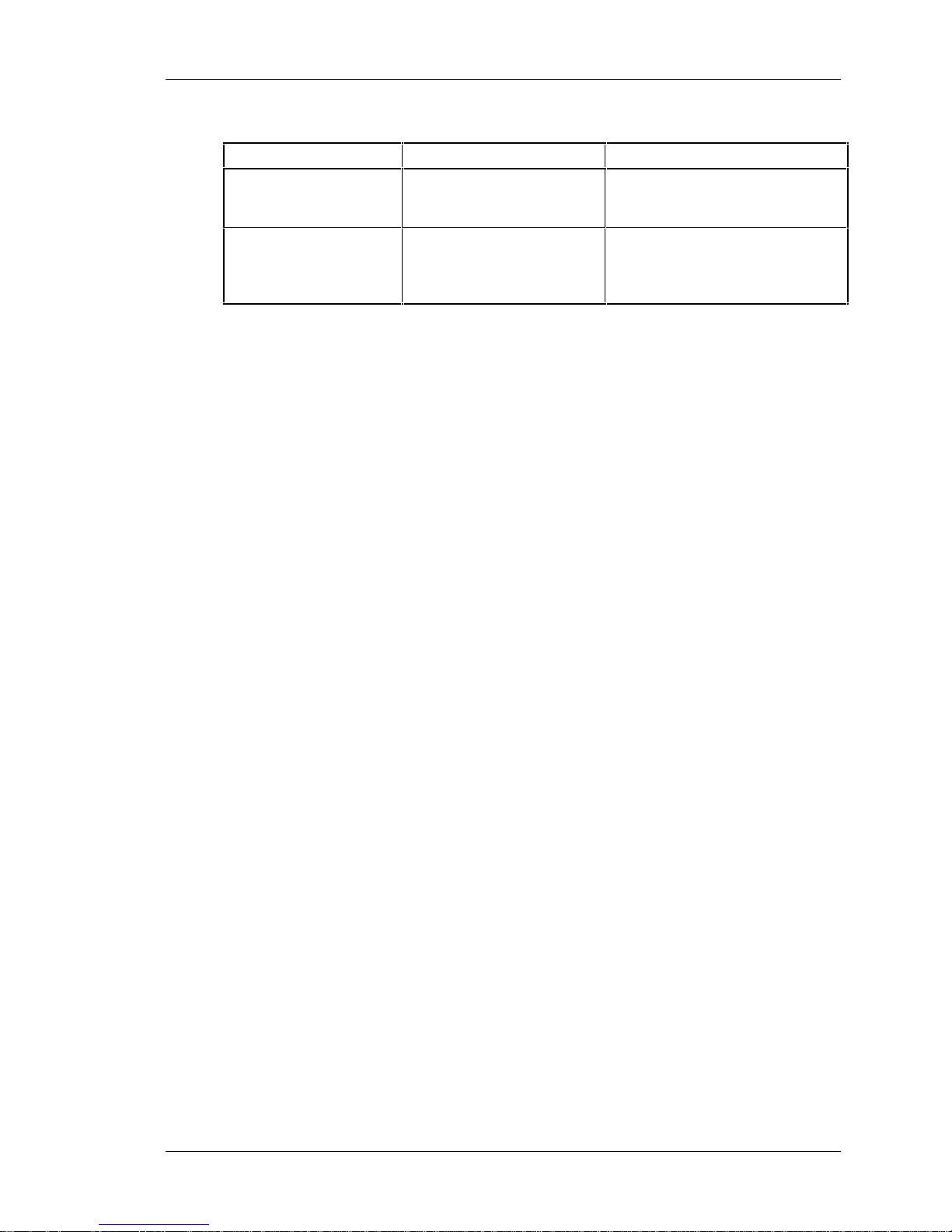
When . . . Then . . . You should . . .
A cartridge is not in the
drive
A cartridge is in the drive. The DRV RDY message
The LDR RDY message
displays before any operation
begins.
displays before the operation
begins.
Press the Open push-button. The
door opens.
Press the Open push-button so the
cartridge unloads from the drive
and moves back into the magazine.
The door opens.
In both situations described in Table 2-20, once you close the door again, a magazine
scan begins and the LDR ACT message is displayed. When the scan completes, the
LDR RDY message is displayed.
Tape Mini-Library User's Guide 2-21
Page 36

Code Update (From Tape)
This chapter describes the Code Update overview and operating procedure.
3.1 Code Update Overview
The SWXTL-BL Cartridge Tape Mini-Library can automatically update the controller
board firmware directly from a tape containing the appropriate information. The user
places the mini-library into code (firmware) update mode via the operator control panel,
and loads the tape cartridge containing the SWXTL-BL code image file. Then, the minilibrary automatically reads and verifies the tape information as a valid SWXTL-BL code
image. If the image data passes all the verifications, the image data installed into the
controller’s non-volatile code memory. This chapter describes how to perform the codeupdate procedure.
CAUTION
3
During the code update, when the new image is actually being
programmed into the FLASH EEPROMs, a power fail (but not
BUS RESET) causes the controller module to be unusable.
When doing a code update, take reasonable precautions to
prevent a power failure.
3.1.1 Updating Code on a Standalone SWXTL-BL
You can update the mini-library code even when the mini-library is not attached to a
SCSI bus. That is, you can update a standalone SWXTL-BL. However, to do an update,
the power-on self-test (POST) must pass first. To pass, POST needs a properly
terminated bus.
3.2 Code Update Procedure
To do the code update, you must have a CompacTape cartridge with a copy of the code
image. This section describes the procedure for updating the code of the drive controller
module in the mini-library. The update is done from a cartridge that stores the code
image. Code update from the host is also supported. For details, see the section on the
SCSI WRITE BUFFER command in the DLT2000 Series Magnetic Tape Product
Manual, (EK-TH4XX-IM).
Tape Mini-Library User's Guide 3-1
Page 37
StorageWorks Tape Mini-Library
3.2.1 Updating the Code on the SWXTL-BL
Update the code on the SWXTL-BL as follows:
1. Obtain or make a CompacTape with the code image of the specified revision level
copied to it.
2. Put the mini-library into the code update mode as follows:
• With the LDR RDY message displayed, press the operator control panel Open push-
button to open the door and remove the magazine. Then close the door.
• Remove all cartridges from the magazine and install the code update cartridge into
the magazine,
• Press the Display Mode push-button until the SCSI IS SEL message is displayed.
• Press and hold the Load/Unload push-button until the SCSI ID SEL message starts
to flash, immediately release the push-button and press the Load/Unload pushbutton again. The CODE UPDATE MODE message is displayed.
3. Press the Open push-button two times to open the magazine door. Load the
magazine with the code update tape into the mini-library and close the door.
4. Wait until the elevator stops scanning the magazine and then press the Load/Unload
push-button to load the code update tape into the tape drive and observe the
following:
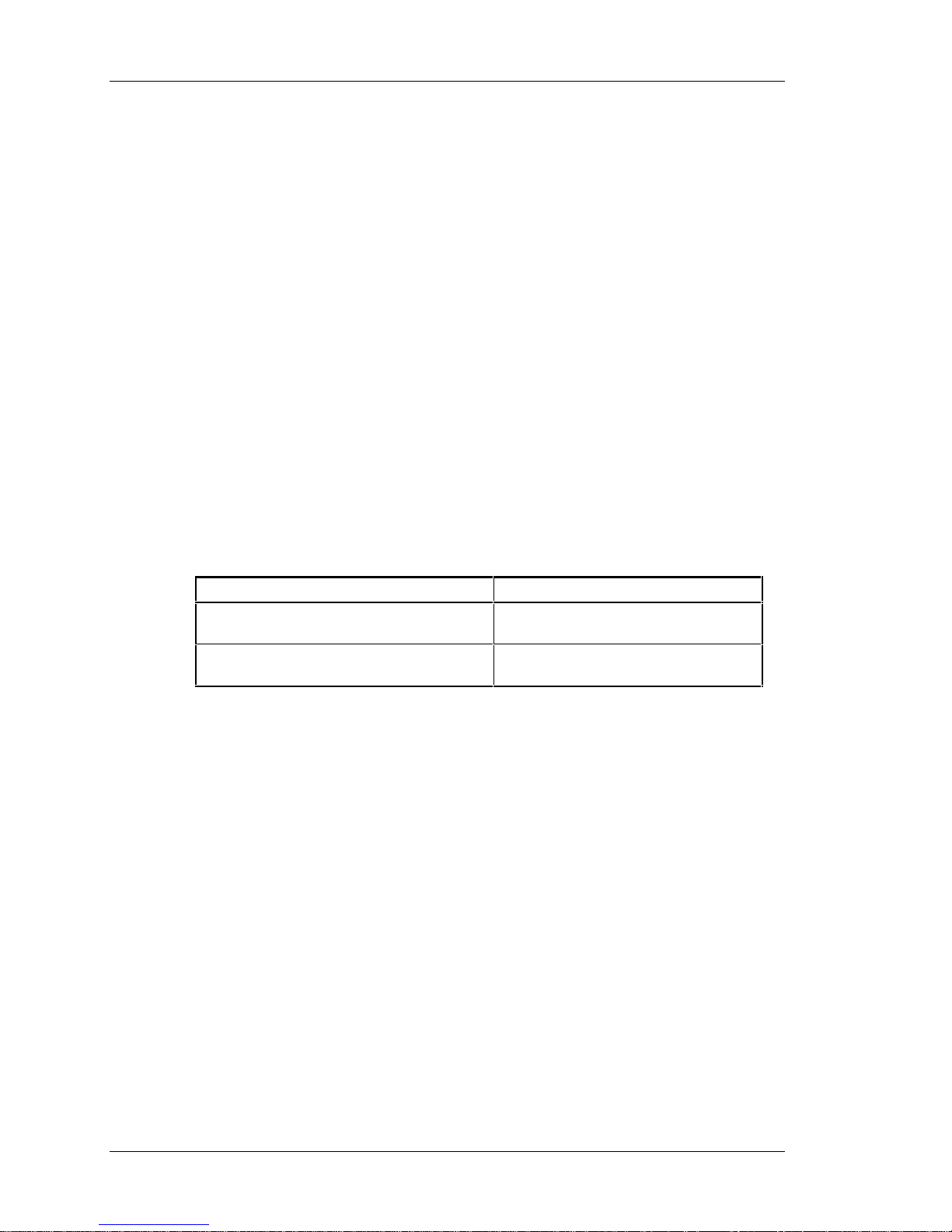
If . . . Then . . .
The drive code revision is the same revision
as that of the update tape.
The drive code revision is not the same
revision as that of the update tape.
The drive code does not go through an
update.
The drive code goes through an update,
taking about 5 minutes.
5. During a drive code update, the drive:
• Automatically reads the tape (calibration and directory processing cause the tape to
move for a few minutes before data is actually read)
• Examines the data
• Verifies the data is a valid SWXTL-BL code image
• When the drive code update completes, the controller’s flash EEPROM memory is
updated with the code image
• Resets and goes through POST, and the code update tape cartridge returns to the
magazine and the LDR RDY message displays
6. If the code update succeeds, the mini-library resets itself and a magazine scan takes
place.
3-2 Tape Mini-Library User's Guide
Page 38

Chapter 3. Code Update (From Tape)
3.2.2 Interpreting the Results
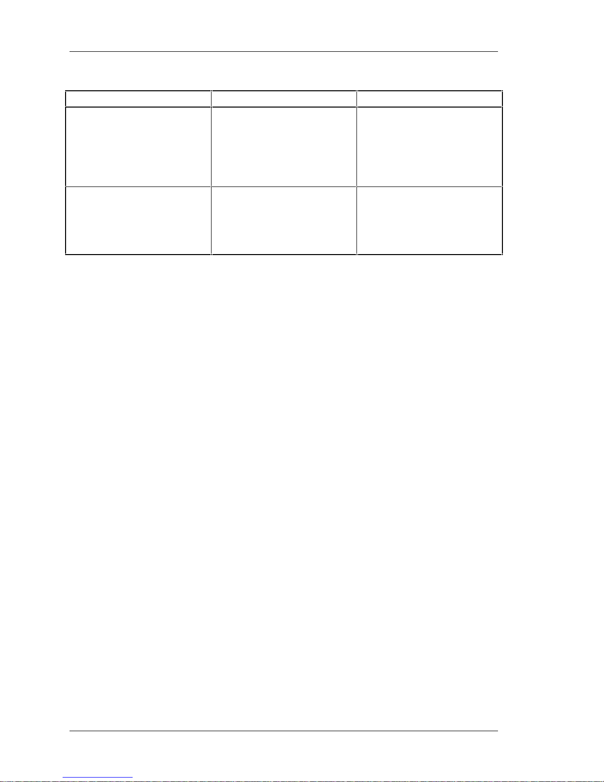
Table 3-1 lists the conditional results of updating the code on the SWXTL-BL.
Table 3-1. Code Update Results
If . . . This means . . . And you should . . .
The code update cartridge
unloads from the drive and loads
into the magazine slot from
which it came
The code update cartridge does
not unload from the drive and
load into the magazine.
The update succeeded. The
controller’s flash EEPROM
memory is updated with the new
firmware image.
The update failed. The drive may
reset and the ERR UNK message
may display. The mini-library
should still be usable, but this
depends on why the update
failed. The reasons for failure
could be:
• The code update cartridge
contains a corrupted image
file or the file is built
improperly.
• The tape cartridge with the
valid update image is not
readable.
Begin operating the mini-library
1. Press the Unload button to
unload the tape cartridge from
the drive.
2. Press the Open button to
open the magazine door.
3. Remove the magazine and
close the door. The mini-library
does an elevator scan.
4. Open the door again. The
message LDR RDY displays.
5. Verify you have the valid
image for your drive type
(variant) in the magazine. Ensure
the image copied to the tape
cartridge is using a block size of
4096 bytes.
If you still cannot do the update,
call your service representative.
1. Press the Unload button to
unload the tape cartridge from
the drive.
2. Press the Open button to
open the magazine door.
3. Remove the magazine and
close door. The mini-library does
an elevator scan.
4. Open the door again. The
message LDR RDY displays.
5. Rebuild the valid image on a
good cartridge.
6. Try the code update
procedure again using the valid
tape image.
If you still cannot do the update,
call your service representative.
Tape Mini-Library User’s Guide 3-3
Page 39
StorageWorks Tape Mini-Library
Table 3-1. Code Update Results (Con’t)
If . . . This means . . . And you should . . .
• A power failure occurs during
the code update. The drive
may be unusable
• A controller failure occurs.
The drive is most likely
unusable and needs to be
replaced.
Try unloading the cartridge from
the drive (as described in this
table) to do the code update
again.
If you still cannot do the update,
call your service representative.
Turn off mini-library power and
turn power back on again.
If you still have a drive controller
failure, call your service
representative.
3-4 Tape Mini-Library User's Guide
Page 40
This chapter provides troubleshooting tips for the mini-library.
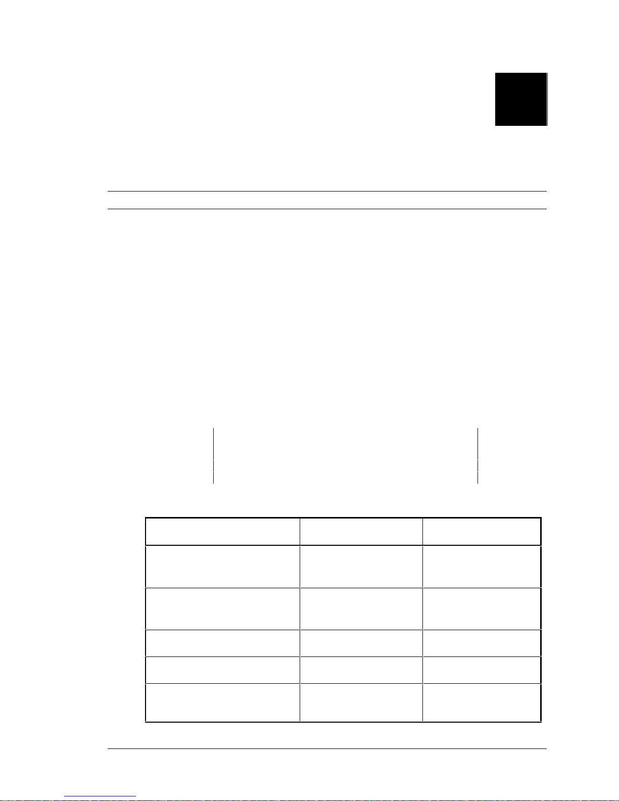
Then you can press this
push-button . . .
Select
Load/Unload
Load/Unload
Load/Unload
Open
4.1 Mini-Library Push-button Conditions
Review the information in the previous chapters to ensure you are correctly operating the
SWXTL-BL mini-library.
Before pressing the Display Mode, Select, Load/Unload, or Open push-buttons on the
operator control panel, check for the conditions listed in Table 4-1 and ensure the
following:
• Mini-library power is turned on
• Magazine door is closed
• Key lock is not set to lock (disable) on the operator control panel
Table 4-1 lists the operating conditions of the push-buttons on the operator control panel.
4
Troubleshooting
NOTE
Do not press the Load/Unload push-button to abort any
function of the mini-library. Consult your applications user’s
guide for abort instructions.
Table 4-1. Mini-Library Push-button Conditions
If you want to . . . First, ensure the . . .
Select another slot in the
magazine
Load the selected cartridge into
the tape drive
Return the selected cartridge to its
original slot in the magazine.
Clear a magazine or loader error. ERR MAG or ERR LDR
Open the door or unload the
cartridge from the drive and open
the door.
• Magazine contains at
least two cartridges
• LDR RDY displays
• Magazine contains at
least one cartridge
• LDR RDY displays
DRV RDY displays
displays
LDR RDY displays
Tape Mini-Library User's Guide 4-1
Page 41
StorageWorks Tape Mini-Library
4.2 Backup Operation Failures
The following manual operations can cause back-up operations to fail during BACKUP:
• Loading write-protected CompacTape III cartridges when executing write operations
• Selecting the incorrect cartridge slot from which to initialize operations
4.3 Avoiding Basic Problems
To avoid basic problems, follow these guidelines when operating the mini-library:
Do not touch the exposed magnetic tape. If the tape leader is
not in the correct position, use a new cartridge.
• Use CompacTape III cartridges
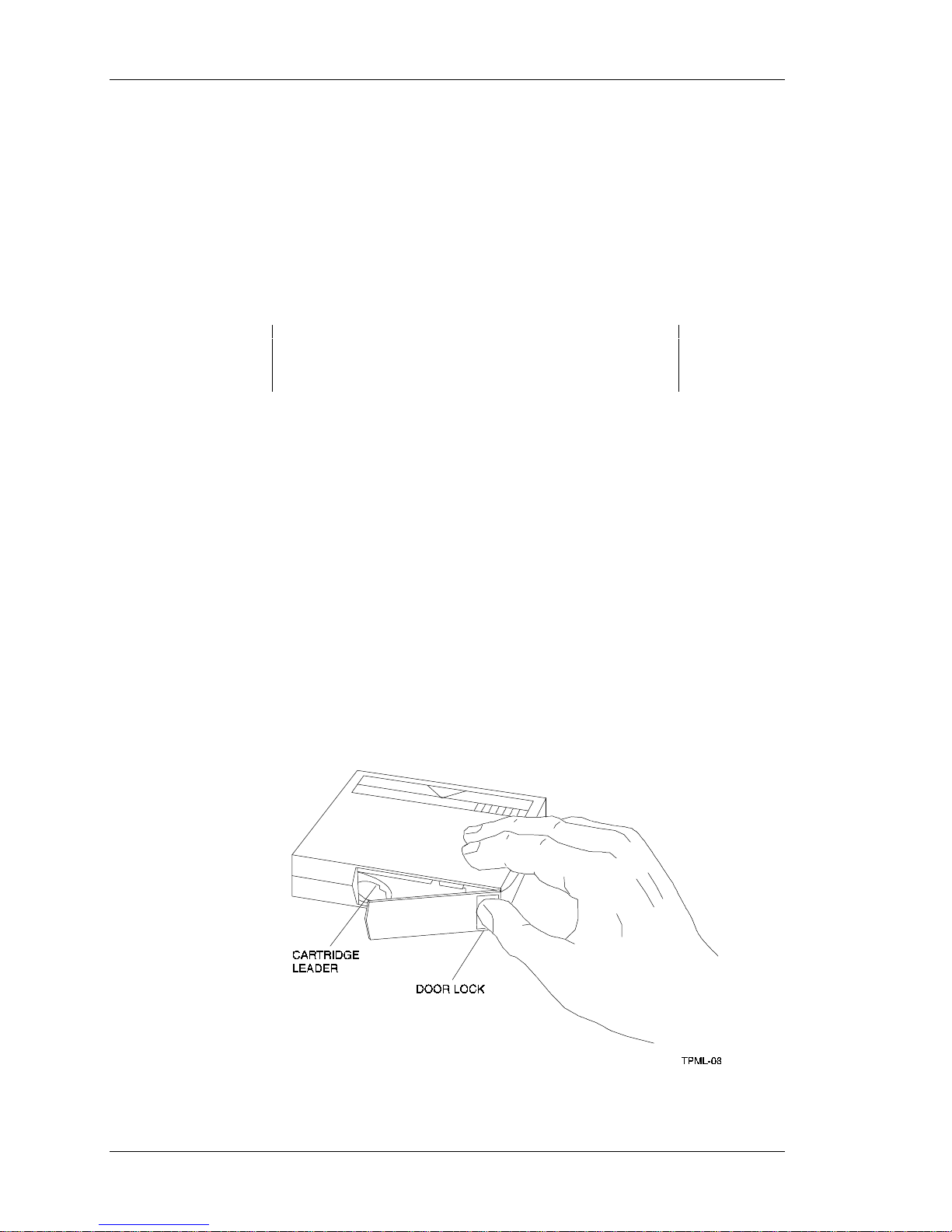
• Check the tape leader in the cartridge by lifting the cartridge latch that opens the
door to expose the leader. Release the door lock by lifting the lock with the thumb
(Figure 4-1). Be sure the leader is in the same position as the one shown in
Figure 4-1
CAUTION
• Ensure the magazine door is fully closed and the current slot is displayed for the
starting cartridge
• Ensure no slots in the magazine are empty between the starting cartridge and the
expected completion cartridge
Figure 4-1. Opening the Cartridge Door to Check the Tape Leader
4-2 Tape Mini-Library User’s Guide
Page 42

4.4 Error Conditions
Error conditions fall into these main categories:
• Magazine Error - In most cases, this error is an operator-correctable condition
indicated when the ERR MAG message displays. If you cannot resolve the error,
call your service representative.
• Loader Error - This a condition that most likely requires service from a service
representative. It is indicated when the ERR LDR message displays.
• • Drive Error
• • Controller Error
• • Unknown Error
4.4.1 Magazine Error Description Cases
A magazine error can occur during any of the following cases:
Case 1 A cartridge was removed from the magazine incorrectly.
Case 2 A cartridge was manually unloaded from the drive.
Chapter 4. Troubleshooting
Case 3 A cartridge that was loaded into the drive by the loader was manually unloaded
and put back into the magazine.
Case 4 A cartridge was manually inserted into the drive. This can occur only if the
loader has been opened, requiring service intervention. It cannot occur under
normal operation.
When the conditions listed above are present, the ERR MAG message displays, showing
a situation that can be corrected by the operator. The only function available at this time
is the Open push-button to open the door and remove the magazine.
4.4.2 Loader Error Description
The ERR LDR message tells you the mini-library has detected a fatal error in the loader
transfer assembly. In some loader transfer assembly errors, the mini-library retries the
error three times before showing an failure. All loader errors cause the ERR LDR
message to display.
4.4.3 Clearing the Loader Error
When you press the Load/Unload push-button, the mini-library attempts to clear the
error. When you press the Open push-button, the door opens to let you access the
magazine.
4.4.4 Drive Error Description
The ERR DRV message tells you the mini-library has detected a fatal error in the tape
drive. In some drive errors, the mini-library retries the error three times before showing a
failure. All drive errors cause the ERR DRV message to display.
Tape Mini-Library User's Guide 4-3
Page 43

StorageWorks Tape Mini-Library
4.4.5 Clearing a Drive Error
When you press the Load/Unload push-button, the mini-library attempts to clear the
error. When you press the Open push-button, the door opens to let you access the
magazine.
4.4.6 Controller Error Description
The ERR CTL message tells you the mini-library has detected a fatal error in the
controller. In some controller errors, the mini-library retries the error three times before
showing a failure. All controller errors cause the ERR CTL message to display.
4.4.7 Clearing the Controller Error
When you press the Load/Unload push-button, the mini-library attempts to clear the
error. When you press the Open push-button, the door opens to let you access the
magazine.
4.5 Power Problems
If the mini-library fan does not turn on, you don’t see a display message, or your system
does not recognize the mini-library:
• Check power plug to ensure it is secure
• Contact your service manager and verify that the mini-library configuration is correct
• If power problems still exist, contact your service representative
4-4 Tape Mini-Library User’s Guide
Page 44

Index
A
ANSI proposed standards, 1-3
Archiving, 1-1
B
Backup
operation failures, 4-2
unattended, 1-1
Bus reset, 3-1
C
Cartridge capacity, 1-1
Changer device, 1-1
Cleaning cartridge, 2-17
Clearing controller error, 4-4
Clearing drive error, 4-4
Clearing loader error, 4-3
Code image, 3-1
Code update (from tape), 3-1
Code update
capability, 1-3
overview, 3-1
procedure, 3-1
results, 3-3
Compatibility, 1-2
Configuring and installing the mini-library,
2-6
Configuration guidelines, 2-6
Compressed mode, 1-1
Controller error description, 4-4
D
Data (continued)
protection, 2-15
reliability, 1-2
transfer rate, 1-1
throughput, 1-1
Default density, 1-2
Drive error description, 4-3
Durability, 1-2
E
ECMA proposed standards, 1-2
Embedded diagnostics, 1-3
error conditions, 4-3
H
Host controller, 3-1
Host-end connections, 2-2
I
Installing magazine into mini-library, 2-19
Installing mini-library, 2-6
Introduction to the mini-library, 2-5
Input SCSI connector, 2-4
K
Key lock, 2-9
L
LCD display, 1-2
Loader error description, 4-3
Data,
capacity, 1-1
compaction, 1-2
compression, 1-1, 1-3
durability, 1-2
Tape Mini-Library User’s Guide Index-1
M
Magazine,
description, 2-16
error description cases, 4-3
Page 45

StorageWorks Tape Mini-Library
Magazine (continued),
inserting, 2-16
opening door, 2-20
Mark directory, 1-1
Media,
durability, 1-2
reliability, 1-2
Messages, 1-2
POST display, 2-7
operator control panel, 2-8
Mini-library
components, 2-1
configuring and installing
default operating modes, 2-12
description, 2-5
key lock, 2-9
loading, 2-9
lock, 2-9
operator control panel, 2-7
power on, 2-2
push-button conditions, 4-1
front panel (diagram), 2-4
rear panel (diagram), 2-3
SCSI interface cables, 2-2
setting SCSI ID, 2-10
shipping screw (diagram), 2-3
troubleshooting, 4-1
unlock, 2-9
unpacking, 2-1
Modes
Code update, 3-2
Default operating, 2-12
Density select, 2-10, 2-13
Native default density, 2-12
Normal, 2-12
SCSI ID select, 2-13
N
Native capacity, 1-1
Native default density, 2-12
2-6
Operator control panel (continued)
display messages, 2-8
Output SCSI connector, 2-4
P
Packing slip, 2-1
Power on, 2-2
POST display messages, 2-7
POST test, 1-3, 2-6
POST test analysis, 2-7
Power cable connection, 2-2
Power problems, 4-4
Programmable host selection, 2-12
R
Read/write cartridge compatibility, 1-3
Removing cartridge from magazine, 2-18
Removing magazine from mini-library, 2-19
Reshipment, 2-2
S
SCSI-2, 1-3
cables, 2-1
cables and connectors, 2-1, 2-2
Command conditions, 2-5
SCSI bus, 2-4, 3-4
cable connection, 2-6
terminator connections, 2-4
configuration rules, 3-4
length, 2-2
interface cable, 2-1, 2-2
Select density mode, 2-10
Selecting cartridge from magazine, 2-19
Setting address of mini-library, 2-10
Setting write-protect switch, 2-16
Shipping screw, 2-2
diagram, 2-3
O
Opening cartridge door, 4-2
Operating mini-library, 2-1
Operator control panel
(diagram), 2-7
functions, 2-8
locked, 2-9
unlocked, 2-10
Index-2 Tape Mini-Library User's Guide
T
Tape cartridge, 2-14
check tape leader, 4-2
cleaning, 2-17
Compac III
compatibility, 1-3
inserting into magazine, 2-16, 2-17
media format, 1-3
loading, 2-19, 2-20
Tape cartridge (continued),
Page 46

ordering, 2-15
removing from magazine, 2-18
selecting from magazine, 2-19
unloading, 2-20
write-protect switch, 2-14
write-protect switch (diagram), 2-15
TZ85, 1-2
TZ86, 1-2
TZ87, 1-2
Troubleshooting the mini-library, 4-1
U
Unpacking, 2-1,
Updating code, 3-1, 3-2
W
Write protect switch, 2-15, 2-16
Index
Tape Mini-Library User's Guide Index-3
Page 47

StorageWorks Tape Mini-Library
Richard:
The foregoing is a tentative attempt
at an automatically generated index.
I believe that I have now worked out
the setups and procedures such that
this sort of an index could be created
(for the size of book you have) in two
to three hours. One of the problems,
however, is that the automatic index
can only be generated after the final
format of the document has been
completed. The codes themselves
could be introduced at any time
during the process, but the index
itself cannot be generated until we
know that you are not going to be
moving anything from one page to
another. I don't have that guarantee
with the files that you gave me,
because they clearly require some
editing, and any changes may move
the end of one or more pages.
One of the problems that I noticed in
the process was a continuing
inconsistency of nomenclature. In
Chapter 1, for example, your
abstract refers to the "Expanded
Storage Pedestal"
and the very next
sentence, opening that chapter,
refers to the "StorageWorks
Expansion Storage Pedestal."
Similarly, we have storage device
carriers, device carriers, carriers,
drive carriers, 3.5-inch drive carriers,
3.5-inch device carriers, 5.25-inch
drive carriers, 5.25-inch device
carriers, etc. If the index had used
more universal entries, that would
have been a serious problem, but I
didn't see any need to use such
entries, so it has been minimal.
However--we now know how to do it,
and it's a lot faster than reading the
text, writing down the entries, and
then typing them into another file.
The basic secrets are as follows, if
the intent is to produce an index that
identifies entries in different chapters
stored in different WinWord files:
1. At the beginning of each such file
(i.e., ahead of the chapter
number), press SHIFT+F9 to
insert a field (appearing on your
screen as two braces.
2. In that field (i.e., between the
braces), type in seq chapter \rn
\h, where the n after the \r switch
is the number of the applicable
chapter.
3. Press F9 to update the field—
which will make it disappear
[presuming that the Field Codes
setting on the Options menu
accessed from your Tools menu
is blank, as it normally is].
4. Pull down the Tools menu, select
the Options function, select the
"hidden Text" (or "All") option
(putting a cross in it) and press
the OK button.
5. Go through your finished text file
looking for things you think
should be in the index (e.g.,
paragraph heading subjects,
such as "Device Addresses";
special terms, such as "hot
swap"; abbreviations &
acronyms, such as SCSI & BBU;
operations, such as "removal of
rear bezel"; etc.) If you see the
desired wording already typed in,
simply highlight the applicable
Index-4 Tape Mini-Library User's Guide
Page 48

character string and then pull
down the Insert menu and select
the Index Entry function and
press the OK button in its dialog
box.
6. If you don't quite see the wording
you want, call up that Index Entry
dialog box anyway and then type
into the available space (up to 64
characters allowed) whatever
wording you think should appear
in the index, and then press the
OK button.
7. If the thing that you type in is to
include a subentry, type in the
primary entry followed by a colon
and then the subentry (i.e., since
there are many things to be said
about the pedestal, you can
presume that pedestal will be a
primary entry; to enter a subentry
for the indicators, you type in
"pedestal: indicators" ... or, in the
case of the already existing
"Pedestal Description," you
simply insert a colon after the first
word).
Index
Tape Mini-Library User's Guide Index-5
Page 49
A
Specifications
This appendix contains the technical specifications for the mini-library and the internal DLT2000 tape drive,
and the definitions of the SCSI command signal set.
Table A-1. Mini-Library Specifications.
Characteristic Specification(s)
Height 11.8 in. (300 mm)
Width 16.3 in. (414 mm)
Depth 10.5 in. (267 mm)
Weight 31 lbs. (14 kg)
Noise Level 35 dB
Maximum number of cartridges Five
Communications interface SCSI-2 bus (single-ended or differential) with a separate
SCSI LUN ID for the mini-library and tape drive
Mechanical load/unload cycle time 20 sec. (typical)
Power requirements (auto ranging)
Voltage 100 to 240 Vac
Frequency 50 to 60 Hz
Power consumption 100 W, max.
Certification
EMI FCC class A, CE Mark Level 1 and VCCI Level 1
Safety (Qualified to:) • UL 1950 Information Technology Inc., Electrical
Business Systems
• CSA C22.2 950-M89-Information Technology Inc.
Electrical Business Systems
• TUV EN60950, IEC 950, DIN VDE 0805 AS 05.92
DIN VDE 0805 AC 05.92
Operating temperature 50° to 104° F (10° to 40° C)
Non operating temperature -40° to 150.8° F (-40° to 66° C) excluding media
Operating humidity 20 to 80% RH, maximum, non condensing
Non operating humidity 10 to 95% RH maximum, non condensing
Operating altitude 0 to 8,000 ft. (0 to 2438 m)
Non-operating altitude 0 to 12,000 ft. (0 to 3658 m)
Tape Mini-Library User’s Guide A–1
Page 50
StorageWorks Tape Mini-Library
Table A-2. DLT2000 Tape Drive Specifications.
Characteristic Specification(s)
Mode of operation Streaming
Media 12.7 mm (1/2 in.) unformatted magnetic tape
Track density 256 tracks/in.
Bit density 62,500 bits/in.
Number of tracks 128
Transfer rate, raw native 1.71 MB/sec.
Transfer rate, user native 1.25 MB/sec.
Transfer rate, user compressed
Tape speed 110 in./sec.
Track format Two-track, parallel serpentine recording
Cartridge capacity 10.0 GB formatted, native
Mini-library capacity
Mini-library backup time About 11 hrs. (100 GB)
Reliability
Subsystem MTBF (10% duty
cycle)
Mechanical 500,000 cycles
1
Assumes a 2:1 compression ratio. However, actual compression ratio may vary as a function of data type.
2
Digital Equipment Corp. does not warrant that the predicted figure represents any particular unit installed for customer use.
The actual figure can vary from unit to unit.
1
2.50 MB/sec., maximum write
3.00 MB/sec., maximum read
20.0 GB formatted, compressed
100 GB
30,000 hrs.
1
2
Table A-3. SCSI Command Set.
SCSI Command Signal
Definitions
Initialize Element Status
Inquiry
Mode Select
Mode Sense
Move Medium
1
Request Sense
Read Element Status
Reserve
Receive Diagnostic Results
Send Diagnostic
Release
Test Unit Ready
1
Random cartridge access is implemented as a SCSI Move Medium command on LUN 1. Implicit sequential cartridge
access can be done using the UNLOAD command on LUN 0 or 1.
A-2 Tape Mini-Library User’s Guide
Page 51

B
™
Product Notes for Novell™ and MS-DOS
This appendix provides information for the system administrator. It should be read before installing and
using the SWXTL-BL tape drive mini-library with a host system operating under the Novell, MS-DOS, or
MS-DOS/WINDOWS operating systems.
B.1 Host SCSI Interface
The SWXTL-BL tape drive mini-library utilizes the standard SCSI-2 command set to
interface to the PC-based host system. Thus, the host system must be equipped with a
SCSI adapter to properly interface the tape drive with the host. For example, the host
SCSI adapter might interface the computer's EISA bus to the SCSI-2 port of the
mini-library.
A host PC SCSI adapter will normally be supplied with a compatible software driver for
use with its operating system. When operating under Novell and MS-DOS or
MS-DOS/WINDOWS operating systems, the software driver must be pre-loaded
according to the SCSI adapter's manufacturers installation procedure to ensure a proper
interface between the mini-library and the host. In addition, a user-level tape read/write
software program may be required to implement tape support under the Novell, MSDOS, or MS-DOS/WINDOWS environments. There are many commercial software
products available that provide host or network-based data backup and restore, archiving,
data logging, etc. functionality for these operating systems.
Before purchasing a user-level software product, ensure that the mini-library is supported
by that product (see note below). Commercial software vendors usually publish a
supported hardware list or have telephone technical support personnel that will answer
questions regarding compatibility of a particular tape drive or other storage devices.
When choosing a software product suitable for your application, follow the software
vendor's installation procedure to implement support for your mini-library.
NOTE
The SWXTL-BL tape drive mini-library is functionally
equivalent to the TZ875 (DEC part no.) tape drive.
Commercial software products that support the TZ875 will
also support the SWXTL-BL.
Tape Mini-Library User's Guide B-1
Page 52

Reader’s Comments
Manual Order Number:
EK-SM1TC-UG. A01
SWXTL-BL 50/100 GB, 5-Cartridge DLT Tape Drive Mini-Library
Digital is committed to providing the best possible products and services. Since our manuals are important
components of our products, we value your comments, corrections, and suggestions for improvements. Please take a
few minutes to fill out and return this form, attaching additional sheets, if needed. Thank you.
Manual Rating Excellent Good Fair Poor
Accuracy (correct presentation of facts) [ ] [ ] [ ] [ ]
Completeness (adequate information) [ ] [ ] [ ] [ ]
Clarity (easy to understand) [ ] [ ] [ ] [ ]
Organization (logical sequence of information) [ ] [ ] [ ] [ ]
Layout (easy to follow subject matter) [ ] [ ] [ ] [ ]
Indexing (easy to locate desired information) [ ] [ ] [ ] [ ]
Errors Noted (please include page, paragraph, table or figure number)
Most-Liked Features
Least-Liked Features
Suggestions for Improvement
Return Address:
Customer Research
Response Center
Attn: Nan Andrews Amish
Digital Equipment Corporation
334 South Street, SHR3-2/S27
Shrewsbury, MA 01545
Name Phone
Title
Company
Street Address
Mail Stop
City State ZIP
Country (if other than USA)
Page 53

 Loading...