


DLT 10/20 GB Cartridge Tape Drive
– StorageWorks Building Block (SWXTL-BA & SWHTL-BA)
– Tabletop Tape Drive (SWXTL-BT)
User’s Guide
EK–SM1TB–UG. E01
Digital Equipment Corporation
Maynard, Massachusetts

Fourth Edition, November 1995
The information in this document is subject to change without notice and should not be construed as a commitment by Digital Equipment Corporation. Digital Equipment Corporation assumes no responsibility for any
errors that may appear in this document.
Restricted Rights: Use, duplication, or disclosure by the U.S. Government is subject to restrictions as set forth
in subparagraph (c) (1) (ii) of the Rights in Technical Data and Computer Software clause at DFARS
252.227-7013.
Digital Equipment Corporation does not give a warranty of any kind regarding the fitness or applicability of
the information content for a particular purpose. The user assumes all responsibility for understanding the
interrelationships of this enclosed information with other affected software or system products.
The disclosure of this information does not grant to the user a license under any patents, pending patents,
trademarks, or copyrights or other rights of Digital Equipment Corporation, or of any third party.
FCC Notice: This equipment has been tested and found to comply with the limits for a Class B digital device,
pursuant to Part 15 of the FCC rules. These limits are designed to provide reasonable protection against
harmful interference in a residential installation. Any changes or modifications made to this equipment may
void the user’s authority to operate this equipment. The shielded interconnect cable, as supplied with the unit,
may not be substituted, nor altered or modified, in any way.
This equipment generates, uses, and can emit radio frequency energy and, if not installed and used in accordance with the instructions, may cause harmful interferences to radio communications. However, there is no
guarantee that interference will not occur in a particular installation. If this equipment does cause harmful
interference to radio or television reception, which can be determined by turning the equipment off and on,
the user is encouraged to try to correct the interference by one or more of the following measures:
• Reorient or relocate the receiving antenna.
• Increase the separation between the equipment and receiver.
• Connect the equipment into an outlet on a circuit different from that to which the receiver is connected.
• Consult your reseller or an experienced radio/TV technician for help.
Copyright © Digital Equipment Corporation 1994, 1995
All Rights Reserved
Printed in U. S. A
The following are trademarks of Digital Equipment Corporation:
DEC
Digital
StorageWorks
VMS
and the Digital Logo:
All other trademarks and registered trademarks used in this publication are the property of their respective
owners.

Contents
1 Introduction
1.1 Product Overview..................................................................................................................1–1
1.2 Design Features.....................................................................................................................1–1
1.2.1 Basic Components .............................................................................................................1–1
1.2.2 Performance Considerations...............................................................................................1–1
1.3 Data Tape..............................................................................................................................1–2
1.3.1 CompacTape III Description..............................................................................................1–2
1.3.2 Cartridge Packaging...........................................................................................................1–3
1.4 Reading and Writing Data.....................................................................................................1–3
1.4.1 Write-Protecting Data........................................................................................................1–3
1.5 Cleaning Tape....................................................................................................................... 1–4
1.5.1 CleaningTape III Description.............................................................................................1–4
1.5.2 CleaningTape III Packaging...............................................................................................1–4
1.5.3 CleaningTape III Cartridge Expiration...............................................................................1–4
1.6 Supplies.................................................................................................................................1–5
1.6.1 Cartridges Provided ...........................................................................................................1–5
1.6.2 How To Order Replacement Cartridges..............................................................................1–5
2 Installation and Operation of the SWXTL-BA SBB
Tape Drive in a Storage Subsystem
2.1 Introduction...........................................................................................................................2–1
2.2 Unpacking.............................................................................................................................2–1
2.3 Preinstallation Procedures .....................................................................................................2–2
2.3.1 Setting the SCSI ID Address of the Tape Drive..................................................................2–2
2.4 Installing the SWXTL-BA SBB Tape Drive Into a StorageWorks Expansion
Storage Subsystem.................................................................................................................2–3
2.5 Power On Self Test (POST)...................................................................................................2–4
3 Installation and Operation of the SWXTL-BT Tabletop Tape Drive
3.1 Introduction...........................................................................................................................3–1
3.2 Unpacking.............................................................................................................................3–1
3.3 Preinstallation Procedures .....................................................................................................3–2
3.3.1 Enabling/Disabling Parity..................................................................................................3–2
3.3.2 Setting the SCSI ID Address of the Tape Drive..................................................................3–2
3.4 Installation of SWXTL-BT Tabletop DLT Tape Drive...........................................................3–4
3.4.1 SWXTL-BT Power On Self Test (POST)...........................................................................3–4
Order Number: EK–SM1TB–UG. E01 iii

StorageWorks DLT 10/20-GB Cartridge Tape Drive
4 Front-Panel Controls & Indicators and Operation
of the 10/20-GB DLT Cartridge Tape Drive
4.1 General .................................................................................................................................4–1
4.2 Front-Panel Controls and Indicators ......................................................................................4–1
4.2.1 Unload Push-Button...........................................................................................................4–2
4.2.2 Cartridge Insert/Release Handle.........................................................................................4–2
4.2.3 D
4.3 Power-On Self-Test (POST) ..................................................................................................4–4
4.4 Status Indication of Tape Drive LEDs....................................................................................4–6
4.5 CompacType III DLT Tape Cassette......................................................................................4–7
4.6 Using and Handling CompacTape III Tape Cassettes.............................................................4–7
4.6.1 Write-Protect Switch..........................................................................................................4–8
4.6.2 Data Protection..................................................................................................................4–8
4.6.3 Loading A Cartridge..........................................................................................................4–9
4.6.4 Tape in Use...................................................................................................................... 4–11
4.6.5 Unloading A Cartridge.....................................................................................................4–11
4.6.6 Using the Tape Cleaning Cartridge..................................................................................4–12
4.6.7 Preserving Cartridges.......................................................................................................4–12
4.7 Selecting Density.................................................................................................................4–13
4.7.1 How To Select Density At The Front Panel...................................................................... 4–14
4.7.1.1 Selection of Compression Mode...................................................................................4–14
4.7.1.2 Density Select Example................................................................................................ 4–15
4.7.2 Density Selection Rules...................................................................................................4–15
ENSITY SELECT Switch................................................................................................ .....4–3
5 Maintenance
5.1 Introduction...........................................................................................................................5–1
5.2 Common Errors.....................................................................................................................5–1
5.2.1 Avoiding Basic Problems...................................................................................................5–1
5.2.2 Error Influences.................................................................................................................5–1
5.3 Cleaning the Heads................................................................................................................5–2
5.4 Inspections ............................................................................................................................5–3
5.4.1 Checking the Cartridge Leader...........................................................................................5–3
5.4.2 Checking the Drive Leader ................................................................................................5–3
5.5 Troubleshooting .................................................................................................................... 5–6
Appendix A Specifications
Appendix B Product Notes for Novell and MS-DOS
B.1 Host SCSI Interface.............................................................................................................. B–1
Appendix C Product Notes for Sun™
C.1 General Information............................................................................................................. C–1
C.2 Modifications Required for SunOS 4.1.x...............................................................................C–1
C.2.1 Installation Procedure .......................................................................................................C–1
C.2.1.1 System Modification ..................................................................................................... C–1
C.2.1.2 Rebuilding of Kernel .................................................................................................... C–2
C.2.1.3 Installation of Tape Drive.............................................................................................. C–2
iv Order Number: EK–SM1TB–UG. E01

C.2.1.4 Rebooting of System ..................................................................................................... C–3
C.2.1.5 Testing the SWXTL SBB .............................................................................................. C–3
C.2.1.6 Verification ................................................................................................................... C–3
C.2.2 Dump Parameters for the Tape Drive................................................................................ C–4
C.3 Modifications Required for Solaris™ 2.3 (or later)...............................................................C–4
C.3.1 Installation Procedure .......................................................................................................C–4
C.3.1.1 System Modification ..................................................................................................... C–4
C.3.1.2 System Shutdown.......................................................................................................... C–6
C.3.1.3 Installation of Tape Drive.............................................................................................. C–6
C.3.1.4 Rebooting of System ..................................................................................................... C–6
C.3.1.5 Test ............................................................................................................................... C–7
C.3.1.6 Verification ................................................................................................................... C–7
C.3.2 Running SUN Diagnostics (Optional) ............................................................................... C–7
C.3.3 Dump Parameters for the Tape Drive................................................................................ C–8
Appendix D Product Notes for IBM™ RS/6000
D.1 Modifications Required to Operate the SWXTL-BA with AIX 3.2.5 (or later)......................D–1
D.1.1 Installing the SWXTL-BA Using the SMIT Command ..................................................... D–1
D.1.2 Installing the SWXTL-BA Using Command-Line Interface..............................................D–2
Contents
Appendix E Product Notes for Hewlett Packard
E.1 General Information..............................................................................................................E–1
E.2 Modifications Required .........................................................................................................E–1
E.2.1 Installation Procedure ........................................................................................................E–1
E.2.1.1 Installation of Tape Drive...............................................................................................E–1
E.2.1.2 System Modification ......................................................................................................E–1
E.3 Series 700 System Device Files..........................................................................................E–2
E.3.1 HP-UX 9.05....................................................................................................................E–3
E.3.2 HP-UX 10.00..................................................................................................................E–4
E.4 Series 800 System Device Files..........................................................................................E–4
E.4.1 HP-UX 9.05....................................................................................................................E–5
E.4.2 HP-UX 10.00..................................................................................................................E–5
E.5 Testing the Tape Drive.......................................................................................................E–5
E.5.1 Verification....................................................................................................................E–6
E.6 Dump Parameters for the Tape Drive.................................................................................E–6
Figures
1–1 Front Panel of 10/20-GB DLT Cartridge Tape Drive .....................................................................1–2
1–2 CompacTape III Cartridge............................................................................................................1–3
1–3 CompacTape III Cleaning Tape.....................................................................................................1–4
2–1 SWXTL-BA Tape Drive SCSI ID Switches...................................................................................2–2
2–2 Installing the SWXTL-BA into an Expansion Storage Pedestal......................................................2–4
2–3 Tape Drive Front Panel Controls and Indicators.............................................................................2–5
3–1 SWXTL-BT Tape Drive SCSI ID Switch Settings.........................................................................3–3
3–2 SWXTL-BT Tape Drive Front Panel Controls and Indicators ........................................................3–4
4–1 Front Panel Layout of 10/20-GB DLT Cartridge Tape Drive..........................................................4–2
4–2 CompacTape III Data Tape Cartridge............................................................................................4–9
4–3 Loading Cartridge Into Tape Drive.............................................................................................. 4–10
Order Number: EK–SM1TB–UG. E01 v

StorageWorks DLT 10/20-GB Cartridge Tape Drive
Figures (continued)
4–4 Unloading Cartridge From Tape Drive.........................................................................................4–12
5–1 Checking Out Cartridge Leader.....................................................................................................5–4
5–2 Correct Engagement of Take-Up Leader in Tape Drive.................................................................5–4
5–3 Correct and Incorrect Positions of Tape Drive Leader....................................................................5–5
Tables
1–1 Ordering Numbers for Cleaning Tape and Data Tapes...................................................................1–5
2–1 SWXTL-BA Tape Drive SCSI ID Switch Settings.........................................................................2–3
3–1 10/20-GB DLT Cartridge Tape Drive SCSI Interface Cables.........................................................3–2
4–1 Right-side Front Panel Indicators and Controls..............................................................................4–3
4–2 Left-side Front Panel Indicators and Controls................................................................................4–4
4–3 Operating States of 10/20-GB DLT Cartridge Tape Drive Unit
Following Initialization..................................................................................................................4–6
4–4 Tape Drive LED Status..................................................................................................................4–7
4–5 Moving Write-Protect switch Before Tape Drive Operation...........................................................4–9
4–6 Moving Write-Protect switch During A Read/Write Operation......................................................4–9
4–7 What is Happening During Cartridge Use (Right-Side Indicators)................................................4–11
4–8 When To Use the Cleaning Cartridge...........................................................................................4–13
4–9 Density Selections Available On 10/20-GB DLT Cartridge Tape Drive.......................................4–14
4–10 Results of Density Selection ........................................................................................................4–16
5–1 Possible Corrections for Common Error Situations........................................................................5–2
5–2 Troubleshooting Table...................................................................................................................5–6
A–1 10/20-GB DLT Cartridge Tape Drive Specifications.....................................................................A–1
vi Order Number: EK–SM1TB–UG. E01

Revision Record
This Revision Record provides a concise publication history of this guide. I t lists the manual revision levels, r elease dates, and reasons for the revisions. It also describes how the changes to affected pages are marked in
the guide.
The following revision history lists all revisions of this publication and their effective dates. The publication part number
is included in the Revision Level column, with the last entry denoting the latest revision. This publication supports the
StorageWorks SWXTL-BA SBB and SWXTL-BT Tabletop Cartridge Tape Drives.
Revision Level Date Summary of Changes
EK–SM1TB–UG. A01 April 1994 Original release
EK–SM1TB–UG. B01 June 1994 Revised artwork and associated text in Chapter 2 to
agree with changed location of SCSI ID switch pack
and SCSI bus connector. Revised artwork and
associated text in Chapter 3 to agree with changed
SCSI ID switch. Revised Chapter 4 to clarify
selection of compression mode.
EK–SM1TB–UG. C01 September 1994 Added Appendix C, Product Notes for Sun™, to
provide application notes pertaining to use with
SunOS™ and Solaris™ systems.
EK–SM1TB–UG. D01 January 1995 Added Appendix D, Product Notes for IBM™
RS/6000 to provide application notes pertaining to
use with AIX™ 3.2.5 (or later) operating systems.
Added Appendix E, Product Notes for Hewlett
Packard 9000 series 700/800 systems to provide
application notes pertaining to use with HP-UX
operating systems.
EK-SM1TB-UG November 1995 Revised Appendix E, Product Notes for Hewlett
Packard™ (naming convention for the HP-UX 10.00
series). Revised Appendix D, Product Notes for
IBM™ RS/6000 (RS/6000 Density Code Tabel
corrections). Revised Appendix C, Product Notes for
Sun™.
Sun™, SunOS™ and Solaris™ are trademarks or registered trademarks of Sun Microsystems, Inc.
™ and AIX™ are trademarks or registered trademarks of IBM, Inc.
IBM
Order Number: EK–SM1TB–UG. E01 vii


About This Guide
This section identifies the users of this guide and describes the contents and structure. In addition, it includes a
list of conventions used in this guide.
This guide provides a product overview, installation, operation, and maintenance information
for the StorageWorks SWXTL-BA SBB and/or SWXTL-BT Tabletop DLT Cartridge Tape
Subsystems, both of which contain a Model 10/20-GB DLT Cartridge Tape Drive.
Intended Audience
This guide is intended for people who will install, operate, and maintain the StorageWorks
SWXTL-BA SBB and/or SWXTL-BT Tabletop DLT Cartridge Tape Subsystems.
Document Structure
This guide contains the following chapters:
Chapter 1. Introduction
Chapter 1 gives an overview of the 10/20-GB DLT Cartridge Tape Drive, describes its com-
ponents, and discusses the drive features. This chapter provides a product overview of the
10/20-GB DLT Cartridge Tape Drive and identifies design features (including basic compo-
nents and performance considerations). The chapter also includes overview descriptions of
the data tape and cleaning tape cartridges used with this equipment, defining the basic func-
tions of each, and identifies what is supplied with the tape drive unit.
Chapter 2. Installation and Operation of the SWXTL-BA SBB Tape Drive in a
Storage Subsystem
Chapter 2 provides specific details pertaining to the SWXTL-BA SBB Tape Drive, which is
designed to be operated in a Digital StorageWorks Expansion Storage Pedestal subsystem.
This chapter describes how to unpack the received drive, how to prepare the drive for instal-
lation in the pedestal, how to set the SCSI ID of the tape drive, how to install the device into
a StorageWorks Expansion Storage Pedestal subsystem, and how to confirm operation in-
tegrity by performing the Power On Self Test (POST) exercise.
Chapter 3. Installation and Operation of the SWXTL-BT Tabletop Tape Drive
Chapter 3 provides specific details pertaining to the SWXTL-BT SBB Tape Drive, which is
designed to be operated as an independent standalone unit on the desktop, a convenient shelf,
or other flat surface. This chapter describes how to unpack the received SWXTL-BT tabletop
drive, how to prepare the drive for installation, how to set the SCSI ID of the tape drive, how
to perform the Power On Self Test (POST) procedure, and how to connect the tape drive to a
host computer.
Order Number: EK–SM1TB–UG. E01 ix

StorageWorks DLT 10/20-GB Cartridge Tape Drive
Chapter 4. Operation
Chapter 4 describes the tape drive’s LED indicators and how to use them to monitor tape
drive operation. This chapter identifies the switches and LED indicators on the front panel of
the 10/20-GB tape drive, describes how to use them (including operation of the power-on
self-test (POST), provides use rules for the CompacTape III DLT cartridge data and cleaning
tapes, gives detailed procedures for correct loading and unloading of the tape cartridges, and
explains how to select a desired density format for recording.
Chapter 5. Maintenance
Chapter 5 describes how to clean the heads of the tape drive, and provides a troubleshooting
table to help diagnose common problems. This chapter describes preventive maintenance and
general troubleshooting for the 10/20-GB DLT Cartridge Tape Drive.
Appendix A. Specifications
Appendix A lists the physical, electrical, cooling, environmental, and environmental stabili-
zation specifications for the tape drive.
Appendix B. Product Notes for Novell™ and MS-DOS™
Appendix B provides information for the system administrator about interfacing the 10/20-
GB DLT Cartridge Tape Drive with a host system operating under the Novell, MS-DOS, or
MS/DOS/WINDOWS operating systems.
Appendix C. Product Notes for Sun™ SunOS 4.1.x and Solaris™ 2.3 Systems
Appendix C provides information for the system administrator about interfacing the SWXTL
10/20-GB DLT Cartridge Tape Drive with a Sun SPARC system running SunOS 4.1.x or
Solaris 2.3 (or later). The information covers the installation of the SWXTL tape drive
hardware and configuring the system to communicate with the drive.
Appendix D. Product Notes for IBM™ AIX™ 3.2.5 (or later) Systems
Appendix D provides information for the system administrator about interfacing the SWXTL
10/20-GB DLT Cartridge Tape Drive with an IBM™ RS/6000 system running AIX™ 3.2.5
(or later). The information covers the installation of the SWXTL tape drive hardware and
configuring the system to communicate with the drive.
Appendix E Product Notes for Hewlett-Packard
Appendix E provides information for the system administrator about interfacing the
SWXTL10/20-GB DLT Cartridge Tape Drive with an HP 9000 Series 700 system running
HP-UX 9.05 (or later) or an HP 9000 Series 800 system running HP-UX 9.04 (or later). The
information covers the installation of the SWXTL tape drive hardware and configuring the
system to communicate with the drive.
x Order Number: EK–SM1TB–UG. E01

Conventions
This guide uses the following conventions:
Style Meaning
boldface type For emphasis
italic type For emphasis and manual titles
__________________________________________
Novell™ is a trademarks of Novell.
MS-DOS™ is a trademark of Micosoft Corporation
SunOS™ and Solaris™ are trademarks of Sun Microsystems, Inc.
IBM™ and AIX™ are tradaemarks of IBM Inc.
Order Number: EK–SM1TB–UG. E01 xi


1
Introduction
This chapter provides a product overview of the Model 10/20-GB DLT Cartridge Tape Drive and identifies design features (including basic components and performance considerations). The chapter also includes overview descriptions of the data tape and cleaning tape cartridges, defining the basic functions of each, and identifies what is supplied with the tape drive.
1.1 Product Overview
The StorageWorks Model 10/20-GB DLT Cartridge Tape Drive is a streaming tape drive
which connects to a SCSI bus. Assuming a 2:1 compression ratio on a CompacTape III car-
tridge, this device can store up to 20 GB of data with compression, or up to 10.0 GB of data
without compression. The primary uses for this drive are data backup, data archiving, and
loading software onto computer systems. The 10/20-GB DLT Cartridge Tape Drive comes
either embedded in a system enclosure, in which case it is identified as an SWXTL-BA Stor-
ageWorks Building Block (SBB), or else in an enclosure with a self-contained power supply,
in which case it is identified as an SWXTL-BT Tabletop DLT Tape Drive. This initial
section of this document discusses the generic information that is common to either version;
subsequent sections will provide details that are specific to either product.
1.2 Design Features
Figure 1–1 shows a view of the front panel, which provides status indicators for system op-
eration, along with an access door for inserting and removing the CompacTape III tape car-
tridge.
1.2.1 Basic Components
The 10/20-GB DLT Cartridge Tape Drive has an integrated SCSI controller module, which
connects to the associated computer system through a SCSI bus attached to that controller
module. The controller module is responsible for processing SCSI commands and for initiat-
ing tape drive operations. In the case of the SWXTL-BA SBB, the connection to the SCSI
bus is made through the StorageWorks Expansion Storage Pedestal, as discussed in Chapter
2. For the SWXTL-BT Tabletop device, however, the connection to the SCSI bus must be
made through an appropriate cable, depending on the type of controller that is used and/or
the desired physical length of cable, as explained in Chapter 3.
1.2.2 Performance Considerations
The performance you can achieve with the 10/20-GB DLT Cartridge Tape Drive can depend
on a number of considerations, including your system processor. When set to compressed
mode, this tape drive theoretically can back up 9 GB of data per hour (tape streaming at
Order Number: EK–SM1TB–UG. E01 1–1

StorageWorks DLT 10/20-GB Cartridge Tape Drive
maximum speed and recording highly compressible data). In a host-based configuration,
proper choice of system processor, cache, hard drive, adapters, and backup software can help
to approach this throughput rate. Host SCSI IO or other computer-intensive operations on the
host CPU will tend to reduce throughput to tape, however.
Figure 1–1 Front Panel of 10/20-GB DLT Cartridge Tape Drive
When data is being passed from or to client workstations in a client-server environment, additional parameters having to do with reduced local area network bandwidth, network traffic,
or lower client workstation performance characteristics will also tend to reduce maximum
throughput to the tape drive.
1.3 Data Tape
1.3.1 CompacTape III Description
The CompacTape III cartridge is a 4-1/8-inch square, dark gray, plastic cartridge, containing
1200 feet of 1/2-inch magnetic, metal particle (MP) tape. A write-protect slide switch on the
front surface lets you select between two positions:
right), which lets the tape drive write data on the tape, and
to the left), which prevents the tape drive from writing over data you want t o preserve (See
Figure 1–2).
1–2 Order Number: EK–SM1TB–UG. E01
WRITE-ENABLED (switch moved to the
WRITE-PROTECTED (switch moved

Figure 1–2 CompacTape III Cartridge
1.3.2 Cartridge Packaging
Chapter1. Introduction
Your CompacTape III cartridge comes supplied with:
1. A set of slide-in labels
2. A cartridge-handling information sheet
1.4 Reading and Writing Data
The 10/20-GB DLT Cartridge Tape Drive writes 64 pairs of tracks — 128 tracks total — on
the CompacTape III tape. The drive reads and writes data in a two-track parallel, serpentine
fashion, traveling the entire length of tape on two tracks (at about 110 inches per second).
The drive then steps the head, reverses tape direction, and continues to read/write on the next
two tracks, repeating this same process for a total of 64 times per tape.
1.4.1 Write-Protecting Data
The CompacTape III cartridge has a write-protect slide-bar switch on its front surface that
lets you prevent accidental erasure of data. When you move that switch to the left, so that a
small orange rectangle is visible in the aperture over the left arrow symbol on the switch (see
Figure 1–2), the tape is write-protected and data cannot be written to the tape. When you
move the switch to the right, so that no orange color shows in the rectangular aperture, the
tape is write-enabled, and the tape drive can write to the tape. The symbols on the slide-bar
switch indicate this function by depicting data flow as a downward-pointing arrow and the
tape medium as a horizontal line below the arrow’s point. The arrow on the left side of the
slide-bar switch depicts a barrier line between the data-flow arrow and the tape; this symbol-
izes that the data cannot reach the tape when the switch is moved to the left. No such barrier
line appears below the arrow on the right side of the switch, indicating that data can flow to
the tape when the switch is moved to the right.
Order Number: EK–SM1TB–UG. E01 1–3

StorageWorks DLT 10/20-GB Cartridge Tape Drive
1.5 Cleaning Tape
1.5.1 CleaningTape III Description
The CleaningTape III cartridge is a 4-1/8-inch square, light yellow, plastic cartridge containing 1200 feet of 1/2-inch cleaning tape (see Figure 1–3). For information on using the
CleaningTape III cartridge, refer to Section 4.6.5 and/or Table 4–8.
Figure 1–3 CompacTape III Cleaning Tape
1.5.2 CleaningTape III Packaging
Your CleaningTape III cartridge comes supplied with:
1. A slide-in label containing 20 boxes, to be checked off following each sequential use of
the CleaningTape III cartridge (refer to Section 1.5.3).
2. A cartridge-handling information sheet.
1.5.3 CleaningTape III Cartridge Expiration
Each use of the CleaningTape III cartridge uses up some of the cleaning area on the tape.
You can use the CleaningTape III cartridge approximately 20 times before the cleaning area
is used up. After that many uses, the cartridge will be ineffective and should be replaced with
a new cartridge.
To keep track of the number of times the tape has been used, mark a checkmark in one of the
20 boxes on the cartridge label after each cleaning. After all 20 boxes have been checked off,
the cartridge should be considered as expired, and you should discard that cartridge and replace it with a new one.
1–4 Order Number: EK–SM1TB–UG. E01

1.6 Supplies
1.6.1 Cartridges Provided
One CompacTape III cartridge and one CleaningTape III cartridge come with each 10/20-GB
DLT Cartridge Tape Drive, in the shipping package.
1.6.2 How To Order Replacement Cartridges
You can order additional cartridges by contacting your Digital reseller or by calling Digital’s
DECdirect ordering service at 1-800-
Table 1–1 lists ordering numbers for various quantities of cartridges for the 10/20-GB DLT
Cartridge Tape Drives:
Table 1–1 Ordering Numbers for Cleaning Tape and Data Tapes
Chapter1. Introduction
DIGITAL in the U.S.A.; in Canada, call 800-267-6215.
Order Number Description
TK85-HC CleaningTape III Head Cleaning Cartridge
TK85K-01 CompacTape III Data Cartridge (quantity, 1)
TK85K-07 CompacTape III Data Cartridge (quantity, 7)
TK85K-A1 CompacTape III Data Cartridge (quantity, 945)
Order Number: EK–SM1TB–UG. E01 1–5


2
Installation and Operation of the
SWXTL-BA SBB Tape Drive
This chapter provides specific details pertaining to unpacking, preinstallation setup, installation, and POST operational testing of the SWXTL-BA StorageWorks Building Block (SBB) Tape Drive, which is designed to be
operated in a Digital StorageWorks Expansion Storage Pedestal.
2.1 Introduction
The SWXTL-BA SBB Tape Drive is housed in an SBB storage carrier and is designed for
installation into a StorageWorks Storage Expansion Pedestal subsystem. The drive occupies
three adjacent slots in the storage subsystem and is configured as one of up to seven devices
on the SCSI bus. This chapter describes how to unpack the received drive, how to prepare the
drive for installation, how to set the SCSI ID of the tape drive, how to install the device into
a StorageWorks Expansion Storage Pedestal subsystem, and how to perform the Power On
Self Test (POST) procedure.
The information in this chapter is divided as follows:
• Unpacking
• Preinstallation setup of the drive (setting SCSI ID Address of the tape drive)
• Installation into the storage subsystem
• POST procedure
2.2 Unpacking
Unpack and inspect the contents of your shipment. It should contain the following items:
• This guide
• One Model 10/20-GB DLT Cartridge Tape Drive
• One blank CompacTape III data cassette tape cartridge
• One CleaningTape III head-cleaning cartridge
• One StorageWorks 10/20-GB DLT Cartridge Tape Drive Operator’s Reference Card
Also, check the contents for damaged components. Notify your vendor immediately if any
items are damaged. Keep all boxes and packing material for reshipment.
Order Number: EK–SM1TB–UG. E01 2–1

StorageWorks DLT 10/20 GB Cartridge Tape Drive
2.3 Preinstallation Procedures
Perform the following procedure before installing the 10/20-GB DLT Cartridge Tape Drive.
2.3.1 Setting the SCSI ID Address of the Tape Drive
The pedestal slots are numbered 0 through 7, from top to bottom, with the power supply occupying slot 7. The SCSI address switches on the rear of the SWXTL-BA SBB Tape Drive
(refer to Figure 2–1) are preset at the factory to automatic — SW-1, SW-2, and SW-3 set off
(to left); SW-4, SW-5, and SW-6 set on (to right). This setting means that the SBB tape drive
will have the address of whichever physical slot is connected. Because of the low position of
the unit’s backplane interface connector, this physical connection will be to the lower of the
three slots occupied by that unit. Physically, this means it will be one of slots 2 through 6, as
applicable. If you want a different specific logical address for any reason (i.e., if you wish to
use SCSI ID 0 or 6, or any specific value in between, regardless of physical location of the
unit), you can set the tape drive to any desired logical address by manually changing the settings of switches SW-1, SW-2, and SW-3 on the SCSI switch pack, as delineated in Table 2–
1, before inserting the SBB into the pedestal.
Figure 2–1 SWXTL-BA Tape Drive SCSI ID Switches
2–2 Order Number: EK–SM1TB–UG. E01

Chapter 2. Installation and Operation of the SWXTL-BA SBB Tape Drive
SW-6
Off
Off
Off
Off
Off
Off
Off
Off
On
Table 2–1 SWXTL-BA Tape Drive SCSI ID Switch Settings
Address SW-1 SW-2 SW-3 SW-4 SW-5
0 Off Off Off Off Off
1 On Off Off Off Off
2 Off On Off Off Off
3 On On Off Off Off
4 Off Off On Off Off
5 On Off On Off Off
6 Off On On Off Off
7* On On On Off Off
Automatic
†
* Normally reserved for host.
† Sets device address to storage subsystem slot number.
________________________________________________________________________________________________________________________
Off Off Off On On
2.4 Installing the SWXTL-BA SBB Tape Drive Into a StorageWorks Expansion
Storage Subsystem
CAUTION
Refer to the applicable documentation for your host computer
and/or your specific operating system before installing the drive.
This installation procedure assumes that you have already installed and appropriately cabled the StorageWorks Storage Expansion Pedestal and have checked out that subsystem as applicable, so that it is ready to receive this SBB unit.
You install the SWXTL-BA SBB tape drive in a storage subsystem by inserting the drive so
that the connector on the lower portion of the rear surface fits into any available SCSI device
storage slot. This means any of slots 2 through 6; the three-slot span of this SBB device
means that you cannot use slot 0 or 1, which are covered if you select slot 2, and slot 7 is
reserved for the pedestal power supply.
The drive can be installed using the hot-swap method where the drive is installed with the
host system powered on and operating, or with the host system powered off. Before using the
hot-swap method, consult your system administrator to ensure that your operating system
supports this type of installation.
To install the tape drive:
1. Open the door on the front bezel of the StorageWorks Expansion Storage Pedestal sub-
system (refer to Figure 2–2) and remove the bezel by pressing down on the plastic
locking tabs at the bottom inside surface of the bezel (just in front of the power supply)
and then pulling the bottom of the bezel forward, after which you can simply lift the
entire bezel assembly free.
2. Remove the filler panel (or any previously mounted SBB) from the desired three adjacent
device slots in the storage subsystem by squeezing the locking handles at the ends of
each respective panel (or SBB) and removing the panel (or SBB).
Order Number: EK–SM1TB–UG. E01 2–3

StorageWorks DLT 10/20 GB Cartridge Tape Drive
3. Install the tape drive in the open slot, sliding the drive in firmly until its locking handles
snap into place.
4. Perform the POST test, as described in the following subsection, to verify the operational
integrity of the drive.
Figure 2–2 Installing the SWXTL-BA into an Expansion Storage Pedestal
2.5 Power-On Self-Test (POST)
The power-on self-test (POST) exercise verifies the proper installation of the tape drive. The
test may be performed with the host computer powered on, if your operating system permits,
or with the SCSI bus either connected or disconnected. Refer to Figure 2–3 for the locations
of the front panel LED indicators on the drive. To execute the power-on self-test, proceed as
follows:
The description of the indicator sequence described in the following procedure describes what happens when the 10/20-GB tape
drive is connected to an active SCSI bus. If the SCSI bus is not
connected, all left-side panel indicators remain on at all times that
power is applied to the unit.
2–4 Order Number: EK–SM1TB–UG. E01
NOTE 1

Chapter 2. Installation and Operation of the SWXTL-BA SBB Tape Drive
NOTE 2
If the WRITE-PROTECTED indicator flashes orange and the TAPE IN
USE indicator flashes yellow continuously for more than 30
seconds in the following test, the POST test has failed. Repeat the
test to clear the failure (power off and then on). If the test still fails,
replace the drive.
Figure 2–3 Tape Drive Front Panel Controls and Indicators
1. Ensure that there is no cassette tape in the drive.
2. Power on the 10/20-GB DLT Cartridge Tape Drive device, either by cycling the pedestal
subsystem power switch off and on or, if other SBB units in that subsystem are active
and should not be powered down, by hot-swapping the SBB unit under test (i.e., pull it
free from the pedestal and then slide it back into its operating position).
3. Observe that all left-side panel indicators initially light, with all right-side indicators then
lighting sequentially, from top to bottom.
4. If the SCSI bus is not connected, all left-side panel indicators will stay lit; if the SCSI
bus is connected, all left-side panel indicators should go out within 1 second after power
is applied, while all right-side panel indicators should remain lighted for 3 to 5 seconds
and then go out, except for the T
APE IN USE indicator, which should continue to blink for
a few seconds while tape mechanism searches for tape and then go out, at which time an
internal beeper sounds to alert the operator and the green O
PERATE HANDLE indicator
becomes steadily lit to indicate that door latch is released and that the cartridge insert/release handle can be pulled up to allow insertion of tape.
Order Number: EK–SM1TB–UG. E01 2–5

StorageWorks DLT 10/20 GB Cartridge Tape Drive
5. Load a cassette tape into the drive and observe the TAPE IN USE indicator. The indicator
initially should blink momentarily at 1-second intervals after the handle is closed
(pushed down) as the tape drive engages the tape, then double-blink at the same interval
while the tape is being moved to the correct position. Depending on whether this is a
new tape or a tape with some previously recorded data, this blinking period should extend for from 20 seconds to a few minutes after the cassette is loaded, until the tape has
reached the applicable position for recording new data, after which the T
cator should remain steadily on.
6. After the unit passes POST, connect the subsystem to your host computer through ap-
propriate SCSI interface cables, and then have your system administrator assign a device
name to the drive, if applicable.
If you are connecting the SBB tape drive to a fast, single-ended
SCSI bus, the interface cable cannot exceed three meters (9.8
feet). If you are connecting the tape drive to a slow, single-ended
SCSI bus, the interface cable can be up to 6 meters (19.7 feet) in
length. In both cases, this maximum cable length includes not only
the length of cable from the pedestal subsystem to the host computer but also the length of cable internal to the subsystem
(including the backplane) and the length of cable internal to the
host computer.
APE IN USE indi-
NOTE
2–6 Order Number: EK–SM1TB–UG. E01

3
Installation and Operation of the
SWXTL-BT Tabletop Tape Drive
This chapter provides specific details pertaining to the SWXTL-BT SBB Tape Drive, that is designed to be
operated as an independent standalone unit on the desktop, a convenient shelf, or other flat surface. The
chapter tells how to unpack the tabletop unit, how to perform required preinstallation adjustments, set the SCSI
address, operate the power-on self-test, and connect the unit to your host system.
3.1 Introduction
CAUTION
Refer to applicable instructions for your specific operating system
before installing the drive and executing the power-on self-test
procedure.
The SWXTL-BT Tabletop Tape Drive is an independent unit that requires a shelf space
measuring at least 9-1/4” wide by 13” deep (plus cable connection space). Connection to
your host computer is accomplished through a SCSI-bus interface cable. To install the drive,
you first must perform applicable preinstallation procedures to enable or disable parity, as
desired, and to set the SCSI ID address to the desired device number. You can then power-up
the drive and confirm that the power-on self-test (POST) procedure confirms the operational
integrity of your tabletop unit. Once you know the tape drive is fully operational, you can
connect an applicable SCSI interface cable from the connector at the rear of the SWXTL-BT
Tape Drive to the SCSI-bus interface card in your host system and, if applicable, terminate
the SCSI bus.
This chapter describes how to unpack the received SWXTL-BT tabletop drive, how to prepare the drive for installation, how to set the parity capability and SCSI ID of the tape drive,
how to perform the initial Power-On Self-Test (POST) procedure, and how to connect the
tape drive to your host computer. The information in this chapter is divided as follows:
• Unpacking
• Preinstallation setup of the drive
• POST procedure
• Connection of the tape drive to your host computer
Order Number: EK–SM1TB–UG. E01 3–1

3.2 Unpacking
Unpack and inspect the contents of your shipment. It should contain the following items:
• This guide
• One SWXTL-BT Tabletop DLT cassette tape drive
• One blank CompacTape III cassette tape cartridge
• One CleaningTape III head-cleaning tape cassette
• One SCSI bus terminator
• One StorageWorks 10/20-GB DLT Cartridge Tape Drive Operator’s Reference Card
Also, check the contents for damaged components. Notify your vendor immediately if any
items are damaged. Keep all boxes and packing material for reshipment.
Confirm that you have received, either as a separate shipment or as part of this same order,
depending on your reseller, an appropriate SCSI-bus interface cable, corresponding to the
type of SCSI interface controller mounted in your computer system. (Refer to Table 3–1).
Table 3–1 10/20-GB DLT Cartridge Tape Drive SCSI Interface Cables
Chapter 3. Installation and Operation of the SWXTL-BT Tabletop Tape Drive
Application Drive-end
Connector
Low-Density toLow-Density
1
Cable
Low-Density to
High-Density
2
Cable
1
The 50-pin low-to-low-density cable is compatible with most ISA-type SCSI-bus adapters.
2
The 50-pin high-density cable is compatible with either of:
a. Most EISA-bus SCSI adapters.
b. Daisy-chain connection to DEC BA350 (Pedestal) or DEC BA353 (Desktop) SCSI storage
expansion cabinets.
_______________________________________________________________________________________________________________________________________________
Low-Density
50-pin
Low-Density
50-pin
3.3 Preinstallation Procedures
Perform the following procedure before installing the SWXTL-BT tape drive.
3.3.1 Setting the SCSI ID Address of the Tape Drive
The SWXTL-BT Tabletop Tape Drive contains a push-button counter switch in the upper
right corner of the rear panel. The push-button counter is preset at the factory to SCSI ID 0,
but you can easily set the tape drive to any desired specific address by manually changing the
setting of the counter. The single-digit counter shows the current SCSI ID address selection.
Each time you press the button located just above the counter readout, the counter (and the
SCSI ID address) increments to the next higher value, until you reach 7, the upper limit.
Each time you press the button located just below the counter readout, the counter (and the
SCSI ID address) decrements to the next lower value, until you reach 0, the lower limit.
Host-end
Connector
Low-Density
50-pin
High-Density
50-pin
Digital SCSI Cable
Part Number
BC19J-1E (18 inches long)
BC19J-06 (2.0 meters long)
BC09D-03 (3.0 feet long)
BC09D-06 (6.0 feet long)
3–2 Order Number: EK–SM1TB–UG. E01

StorageWorks DLT 10/20-GB Cartridge Tape Drive
3.4 Installation of SWXTL-BT Tabletop DLT Tape Drive
The SWXTL-BT Tabletop DLT Tape Drive is an independent unit that requires a shelf space
measuring at least 9-1/4” wide by 13” deep (plus cable connection space). Connect the tape
drive to an appropriate power source, using the supplied power cable, as follows:
1. Plug the female end of the power cord into the power jack at the rear face of the tape
drive unit and then plug the other end of that cord into an appropriate power source,
providing 120/240 Vac at 50/60 Hz.
2. Perform the POST test described in the following subsection t o verify the operational in-
tegrity of the drive.
3.4.1 SWXTL-BT Power-On Self-Test (POST)
The POST test verifies operational integrity of the tape drive. The first time that you run this
test, the SWXTL-BT tape drive unit should be disconnected from the host computer, with no
tape cartridge in the drive. Once you have confirmed that the tape drive is operational, you
can run the POST checkout with the host system connected, as desired. Refer to Figure 3-1
for the locations of the front panel LED indicators on the drive.
To execute the power-on self-test, proceed as follows:
NOTE 1
The description of indicator sequence described in the following
procedure describes what happens when the 10/20-GB tape drive
is connected to an active SCSI bus. If the SCSI bus is not connected, all left-side panel indicators remain on at all times that
power is applied to the unit.
NOTE 2
If the WRITE-PROTECTED indicator flashes orange and the TAPE IN
USE indicator flashes yellow continuously for more than 30 seconds in the following test, then the POST test has failed. Repeat
the test to clear the failure (power off and then on). If the test still
fails, replace the drive.
1. Ensure that there is no cassette tape in the drive.
2. Power on the tape drive (depress top “1” portion of 1/0 rocker switch on rear panel) and
observe that all left-side panel indicators initially light, with all right-side indicators then
lighting sequentially, from top to bottom.
3. If the SCSI bus is not connected, all left-side panel indicators will stay lit; if the SCSI
bus is connected, all left-side panel indicators should go out within 1 second after power
is applied, while all right-side panel indicators should remain lighted for 3 to 5 seconds
and then go out, except for T
seconds while tape mechanism searches for tape and then goes out. When the T
APE IN USE indicator, which continues to blink for a few
APE IN
USE indicator goes out, an internal beeper sounds to alert the operator and the green
PERATE HANDLE indicator becomes steadily lit to indicate that the door latch is re-
O
leased and that the cartridge insert/release handle can be pulled up to allow insertion of
tape.
Order Number: EK–SM1TB–UG. E01 3–3

Chapter 3. Installation and Operation of the SWXTL-BT Tabletop Tape Drive
Figure 3–1 SWXTL-BT Tape Drive Front Panel Controls and Indicators
4. Load a cassette tape into the drive (refer to Figure 4–3) and observe the TAPE IN USE indicator. The indicator initially should blink momentarily at 1-second intervals after the
handle is closed (pushed down) as the tape drive engages the tape, then double-blink at
the same interval while the tape is being moved to the correct position. Depending on
whether this is a new tape or a tape with some previously recorded data, this blinking
period should extend from 20 seconds to a few minutes after the cassette is loaded, until
the tape has reached the applicable position for recording new data, after which the T
IN
USE indicator should remain steadily on.
APE
5. After the unit passes POST, connect the unit to your host computer through appropriate
SCSI interface cables, as follows. If applicable, have your system administrator assign a
device name to the drive.
NOTE
If you are connecting the tabletop tape drive to a fast, singleended SCSI bus, the interface cable cannot exceed three meters
(9.8 feet). If you are connecting the tape drive to a slow, singleended SCSI bus, the interface cable can be up to 6 meters (19.7
feet) in length. Table 3–1 provides part-number identifications for
ordering appropriate cables.
a. Connect the appropriate 50-pin-connector end of the SCSI cable to either of the
two vertically oriented jacks at the upper right rear of the tape drive unit.
b. If this tape drive is the last unit on the SCSI bus, make sure that the supplied
terminator is securely fastened in place in the adjacent connector.
3–4 Order Number: EK–SM1TB–UG. E01

StorageWorks DLT 10/20-GB Cartridge Tape Drive
c. Connect the other end of the SCSI cable to the applicable connector provided on
the SCSI controller card in your host system.
d. After the unit is connected to the SCSI bus, you may wish to repeat the power-on
self-test exercise to confirm the operational integrity of all connections.
Order Number: EK–SM1TB–UG. E01 3–5


4
Controls, Indicators, and Operation of the
10/20 GB DLT Cartridge Tape Drive
This chapter identifies the switches and LED indicators on the front panel of the 10/20-GB DLT Cartridge Tape
Drive, describes how to use them (including operation of the power-on self-test (POST), provides use rules f or
the CompacTape III cartridge data and cleaning tapes, gives detailed procedures for correct loading and unloading of the tape cartridges, and explains how to select a desired density format for recording.
4.1 General
Digital’s 10/20-GB-family of DLT Tape Drives offer outstanding performance and integrity,
combined with ease of use. All normal-use operator controls are mounted on the front panel,
consisting of two push-button switches, a pull-down handle, and several color-differentiated
LED indicators to indicate operational status at any given time. The drive uses these indicators to “report” when the unit is ready for a tape, data format of the tape currently mounted,
when the heads need to be cleaned, and when it is safe to take a tape out of the drive, as well
as whether or not the tape cartridge currently is write-protected.
4.2 Front-Panel Controls and Indicators
All operating controls are located on the front panel (refer to Figure 4–1).
The cartridge insert/release handle provides simplified tape loading and unloading proce-
dures, printed on the handle. This handle must be pulled down in order for a tape cartridge to
be loaded or removed, as described in the following procedures, but must not be pulled down
unless the green O
The right-side front panel of the tape cassette drive contains four indicators (W
PROTECTED, TAPE IN USE, USE CLEANING TAPE, and OPERATE HANDLE LEDs) and one
push-button switch (U
Table 4–1 identifies each of these indicators/controls and gives the operating condition and
function of each one.
The left-side front panel of the tape cassette drive contains five indicators (TK85, TK86,
TZ87, C
SELECT push-button). Table 4–2 identifies each of these indicators/controls and gives the
operating condition and function of each one.
OMPRESS, and DENSITY OVERRIDE LEDs) and one push-button switch (DENSITY
PERATE HANDLE indicator is lit.
NLOAD push-button).
RITE
Order Number: EK–SM1TB–UG. E01 4–1

StorageWorks DLT 10/20 GB Cartridge Tape Drive
Figure 4–1 SWXTL-BT Tape Drive Front Panel Controls and Indicators
4.2.1 UNLOAD Push-Button
CAUTION
Pressing the UNLOAD push-button during normal tape operations
may halt the tape and result in the loss of data.
Activation of the UNLOAD push-button causes the tape drive to rewind the tape and then unload the tape from the tape drive mechanism back into the cartridge. The tape must be completely rewound and unloaded into the cartridge before you remove the cartridge from the
drive. Depending on the tape position when you press the U
NLOAD push-button, an unload-
ing operation may take from 10 seconds up to 2 minutes.
In the event that the tape drive is writing data to the tape when you press the U
NLOAD push-
button, the 10/20-GB tape drive flushes any buffered write data to the medium before beginning the unloading sequence.
If the drive is in error state (all four right-side panel indicators flashing), pushing the
U
NLOAD push-button causes the tape drive to reset and unload the tape, if possible.
4.2.2 Cartridge Insert/Release Handle
Operate the cartridge insert/release handle to load a cartridge or to eject a cartridge only when
the Operate Handle indicator is lit. The handle lifts to the open position and lowers to the
closed position. (See Section 4.6.3 for cartridge loading procedures, Section 4.6.6 for cartridge unloading procedures.)
4–2 Order Number: EK–SM1TB–UG. E01

Chapter 4. Controls, Indicators, and Operation of 10/20-GB DLT Cartridge Tape Drive
Table 4–1 Right-side Front Panel Indicators and Controls
Label Color State Operating Condition or Function
Write Protected Orange On Loaded tape is write-protected.
Off Loaded tape is write-enabled.
Tape in Use Yellow On Tape is loaded, ready for use.
Blinking Tape is moving.
Use Cleaning Tape Yellow On Drive heads need cleaning, or else
current data cartridge is bad.
Remaining on after
you unload cleaning
tape.
Turns on again
when data cartridge
is loaded after
cleaning.
Off Cleaning is complete or un-
OPERATE HANDLE Green On Cartridge insert/release handle is
Off Cartridge insert/release handle is
UNLOAD Recessed
(pushed in)
At rest
(out)
All right-side front
panel indicators
On (simultaneously) Power-on self-test is starting.
Blinking An error has occurred. Press the
Cleaning tape attempted to clean
the drive heads, but was expired
(insufficient cleaning area), so
heads were not adequately
cleaned.
Data cartridge may be defective; try
another cartridge.
necessary.
unlocked and can be operated.
locked. Do not operate handle.
Used to unlock the tape cassette
door handle (press and hold for 1 to
2 seconds).
Normal inactive condition for this
spring-loaded push-button switch.
Unload push-button or turn drive
power off and then on again to clear
the error.
4.2.3 DENSITY SELECT Switch
Activation (momentary, only) of the DENSITY SELECT push-button causes the tape drive first
to enter the density-select mode and then, with each subsequent momentary action, to select
the next-in-sequence density selection. In addition, this switch also functions as an
enable/disable selection switch for the tape drive’s compression capability when the drive is
operating in the TZ87 density mode, as discussed in section 4.7.1.1.
Order Number: EK–SM1TB–UG. E01 4–3

StorageWorks DLT 10/20 GB Cartridge Tape Drive
Table 4–2 Left-side Front Panel Indicators and Controls
Label Color State Operating Condition or Function
TK85 Yellow On Indicates tape was last recorded in
Blinking Indicates tape was last recorded in
TK86 Yellow On Indicates tape was last recorded in
Blinking Indicates tape was last recorded in
TZ87 Yellow On (default) Indicates tape was last recorded in TZ87
Blinking Indicates tape was last recorded in
Off Compression mode is disabled.
Compress Yellow On Compression mode is enabled.
Density Override Yellow On A density selection has been set from
Off (default) Density selection is under host control or
Blinking Unit is in density selection mode;
Density Select Recessed
(pushed in)
At rest
(out)
TK85 format.
another density but has been selected
for recording in TK85 density. (You
select this density for a write from BOT.)
TK86 format.
another density but has been selected
for recording in TK86 density. (You
select this density for a write from BOT.)
format.
another density but has been selected
for recording in TZ87 density. (You
select this density for a write from BOT.)
(Compression can be done in TZ87
density, only.)
the drive’s front panel.
else is automatic.
pressing Density Select push-button at
this time will cause next-higher density
option to be selected.
If Density Override indicator is off,
activates density selection mode,
causing that indicator to blink. If Density
Override indicator is blinking (meaning
density selection mode is already
active), causes next higher density
option to be selected.
Normal inactive condition for this springloaded push-button switch.
4.3 Power-On Self-Test (POST)
The POST (Power-On Self-Test) test , which is performed automatically whenever the
10/20-GB tape drive is powered on, verifies operational integrity of the tape drive. Operation
of the POST exercise for the different models is delineated in Section 2.5 for the SWXTLBT SBB and Section 3.4.1 for the SWXTL-BT Tabletop, as part of the installation
procedures, but is repeated here, generically, for convenience. The operation may be
4–4 Order Number: EK–SM1TB–UG. E01

Chapter 4. Controls, Indicators, and Operation of 10/20-GB DLT Cartridge Tape Drive
performed with the host system power on (if your operating system permits) or off, and with
the SCSI bus connected or disconnected. (Refer to Figure 4–1 for the locations of the front
panel LED indicators on the drive.)
NOTE 1
The description of indicator sequence described in this procedure,
as in the associated tables, describes what happens when the
10/20-GB unit is connected to an active SCSI bus. If the SCSI bus
is not connected, all left-side panel indicators remain on at all
times that power is applied to the unit.
To execute POST, proceed as follows:
NOTE 2
If the WRITE-PROTECTED indicator flashes orange and the TAPE IN
USE indicator flashes yellow continuously for more than 30 seconds in the POST exercise, then the test has failed. Repeat the
test to clear the failure (power off and then on). If the test still fails,
replace the drive.
1. Power on the tape drive (if you are using the tabletop unit, depress top “1” portion of 1/0
rocker switch on the rear panel; if you are using an SBB mounted in a storage pedestal,
turn on pedestal power or else pull the SBB tape drive out and then push it back into
place).
2. Observe that all left-side panel indicators initially light, with all right-side indicators then
lighting sequentially, from top to bottom.
If the SCSI bus is not connected, all left-side panel indicators will stay lit; if the SCSI
bus is connected, all left-side panel indicators should go out within 1 second after power
is applied, while all right-side panel indicators should remain lighted for 3 to 5 seconds
and then go out except for T
APE IN USE indicator, which continues to blink for a few
seconds while tape mechanism searches for tape. Subsequent indicator activity depends
on whether or not a tape cartridge currently is mounted in the tape drive, as defined in
Table 4–3. (If no tape is present, the T
APE IN USE indicator continues to blink until the
applicable point for recording new data is under the recording head, at which time that
indicator becomes steadily lit; if no cartridge is mounted, the Tape in Use indicator goes
out, a transducer inside the unit beeps to alert you, and the green O
PERATE HANDLE
indicator becomes steadily lit to indicate that the door latch is released and that you can
pull up the cartridge insert/release handle to allow insertion of tape.)
Following initialization, the drive is in one of the four states defined in Table 4–3.
NOTE
Under normal conditions, you should not power up a tape drive
with a tape cartridge mounted, so that only conditions a and d in
Table 4–3 would apply. The two intervening conditions, describing
situations in which a tape was already mounted before power was
applied, are included to cover emergency situations.
Order Number: EK–SM1TB–UG. E01 4–5

StorageWorks DLT 10/20 GB Cartridge Tape Drive
Table 4–3 Operating States of 10/20-GB DLT Cartridge Tape Drive Unit
Following Initialization
Starting Condition Status Light Sequence
a. If no tape cartridge is
mounted in drive and the
drive passes POST:
b. If a cartridge is present in
the drive and the cartridge
insert/release handle is
1
.
down
c. If a cartridge is present in
the drive and the cartridge
insert/release handle is up.
d. If the drive detects an error
condition.
2
(1) The yellow T
APE IN USE light turns off.
(2) The internal audio-transducer alarm beeps.
(3) The green O
PERATE HANDLE light turns on.
(4) The handle is unlatched.
You can now raise the handle and insert a tape car-
tridge into the drive.
(1) The drive loads the tape cartridge.
(2) The yellow T
APE-IN-USE light blinks while the
tape is mounting and then lights steadily.
(3) The left-side indicator corresponding with the
last-written density format of the current tape
cartridge lights.
(4) The D
ENSITY OVERRIDE blinks.
(5) You can now select a density (refer to Section
4.7.1); the drive is ready for use.
(1) The yellow TAPE IN USE light turns off.
(2) The internal audio transducer beeps.
(3) The green O
PERATE HANDLE light flashes.
When you lower the handle, the cartridge loads.
All right- or left-side lights blink repeatedly.
Try to unload the tape and reinitialize the drive by
pressing the Unload push-button or by turning drive
power off and then on again (or, if you have an SBB,
by hot-swapping that unit). If you do this, the right- or
left-side lights stop blinking and the drive tries to
reinitialize; if the attempt succeeds, the lights momentarily turn on steadily again and then go off.
1
Not recommended. Shutting down power while a tape cartridge is still mounted in the
drive can result in damage either to the tape cartridge (and/or its data) or to the drive,
itself.
2
Not recommended.
4.4 Status Indication of Tape Drive LEDs
The status of the tape drive under different conditions is indicated by the WRITE PROTECTED
and TAPE IN USE LEDs. In the normal operating state, the WRITE PROTECTED LED only
indicates the write-protect status and the T
and load status. Table 4–4 describes the status conditions represented by the LEDs. Refer to
Figure 4–1 to identify the LEDs on the front panel.
APE IN USE LED only indicates the drive activity
4–6 Order Number: EK–SM1TB–UG. E01

Chapter 4. Controls, Indicators, and Operation of 10/20-GB DLT Cartridge Tape Drive
Table 4–4 Tape Drive LED Status
Status WRITE PROTECTED LED TAPE IN USE LED
No tape loaded. Off Off
Tape loaded, write en-
abled.
Tape loaded, write-pro-
tected.
No SCSI/drive activity. Off
SCSI/drive activity. Off
Load sequence. Off
Unload sequence Off†, goes off. Flashes yellow @≈1-second interval
Reset sequence Orange
Power on self test
(POST)
Test complete, no failure.
Test failure, drive fault. Flashes orange @ 2 Hz. Double-flashes yellow @≈1-second
†
If cassette is write-protected, orange WRITE-PROTECTED LED will light.
_______________________________________________________________________________________________________________________________________
Off Yellow
Orange Yellow
†
†
†
†
Off
Flashes orange @ 2 Hz for
first few seconds, then goes
off for remainder of powerup test sequence.
Resume normal operation,
†
.
off
Yellow (steady)
Blinks on and off to track activity
Blinks yellow @≈1-second interval (25%
on).
Yellow continuously when done.
Indicates drive activity.
(25% on).
Goes off when done.
Indicates drive activity.
Yellow, blinking.
Normal indications.
Double-flashes yellow @≈1-second
interval for length of test.
Normal activity indications when test
complete.
interval.
4.5 CompacType III DLT Tape Cassette
The tape cassette contains a write-protect slide-bar switch (Figure 4–2) which is the same
color as the body of the tape cassette but exposes an orange area in a rectangular aperture
above the arrow on the left side of that switch when in the write-protect position. To "writeprotect" the tape, slide the tab to the left before loading the tape in the drive or before starting
any write operations. To "write-enable" the tape, slide the switch to the right before loading
the tape in the drive or before any write operations.
4.6 Using and Handling CompacTape III Tape Cassettes
The data tape cartridge is a 4-1/8-inch, gray, plastic cartridge containing 1200 feet of 1/2inch magnetic metal particle tape. The medium is a half-inch cartridge or ANSI-compatible
equivalent. It is written and read using the interchange format proposed in the applicable
pending ANSI X3B5 project.
Order Number: EK–SM1TB–UG. E01 4–7

StorageWorks DLT 10/20 GB Cartridge Tape Drive
You can order the data cartridge (Part No. TK85-01) and/or the
cleaning cartridge (Part No. TK85-HC) from your reseller or by
calling DECdirect at 800-DIGITAL in the U.S.A. o r 800-27-6215 in
Canada. (Refer to Table 1-1 for quantity-order part numbers.)
Appropriate label cards are supplied with each tape cartridge. Always place the label in the recessed area on the cartridge. Never
affix a label over another label. Also, please note that any substitute media must meet ANSI X3B5 certification requirements.
To ensure optimal performance from your cassettes tapes, observe the following guidelines
when using and handling the tapes.
• Avoid placing the tape cassettes near sources of electromagnetic radiation such as
terminals, video, or X-ray equipment. Radiation from this type of equipment can erase
or corrupt data on the tape
• Keep tape cassettes out of direct sunlight and away from heaters and sources of heat
NOTE
CAUTION
• Store tape cassettes and cleaning cassette at room temperatures between +5°C and
+32°C (40°F through 90°F).
• Store cassettes in a dust-free environment where the relative humidity is within the
range from 20% to 60%.
4.6.1 Write-Protect Switch
The tape cartridge has a write-protect slide-bar switch on the right side of its front surface so
that you can prevent the accidental overwriting of data stored on the tape (see Figure 4–2).
To read or copy from
orange area is exposed in the rectangular aperture directly over the left-side arrow on the
switch, indicating that the tape is in its “write-protected" state. This prevents writing to the
tape and ensures that data will not be accidentally overwritten. Use the following guidelines
when setting the write-protect tab:
• If you are reading data (copying from tape), set the write-protect tab to “Write Protected”
(to the left, orange area showing).
• If you are writing data (writing to tape), set the write-protect tab to “Write Enabled” (to
the right, orange area not
• When loading a tape cassette into the drive, make sure the cassette's write-protect tab is
on the right, facing you.
the tape cassette, slide the write-protect bar-switch to the left, so that an
showing).
4.6.2 Data Protection
If you move the cartridge write-protect switch to the left, the drive turns on the WRITE
PROTECTED LED immediately. If the drive is writing to the tape when you move the switch,
however, write-protection does not take effect until that write has been completed.
4–8 Order Number: EK–SM1TB–UG. E01

Chapter 4. Controls, Indicators, and Operation of 10/20-GB DLT Cartridge Tape Drive
Figure 4–2 CompacTape III Data Tape Cartridge
Table 4–5 describes what happens to data protection when you move the write-protect switch
before loading the cassette.
Table 4–5 Moving Write-Protect switch Before Tape Drive Operation
If you move the Write Protect switch ... Then ...
To the left, with the orange area showing
through the aperture above the left arrow
symbol on the switch ...
To the right, with no orange area showing in the
aperture above the left arrow on the switch ...
The tape drive cannot write data to the
tape.
The tape drive can write data to the tape (if
the tape is not software write-protected).
Table 4–6 describes what happens to data protection when you move the write-protect switch
during operation:
Table 4–6 Moving Write-Protect switch During A Read/Write Operation
If you move the Write Protect switch ... Then ...
From the write-protected position (left) to the
write-enabled position (right, no orange area
showing in aperture above left arrow symbol) ...
From the write-enabled position (right) to the
write-protected position (left, orange area
showing in aperture) ...
The tape becomes write-enabled after
variable amount of time (in the order of
seconds).
The tape becomes write-protected after a
variable amount of time (in the order of
seconds, unless write operation is in
process, in which case the effect does not
become active until that write operation is
completed).
a
Order Number: EK–SM1TB–UG. E01 4–9

StorageWorks DLT 10/20 GB Cartridge Tape Drive
4.6.3 Loading A Cartridge
The cartridge insert/release handle on the front of the drive provides outline procedures for
loading a cartridge into the tape drive (right side of handle) and unloading a cartridge from
the drive (left side of handle). The following is a more detailed version of the procedure for
loading a cartridge (refer to Figure 4–3).
Never operate the cartridge insert/release handle unless the green
Operate Handle indicator is steadily lit.
1. When the green OPERATE HANDLE indicator is lit steadily, pull the cartridge insert/release handle open by pulling the bottom edge up and forward.
2. Insert the rear end of the cartridge (opposite from the surface containing the write-protect
switch) into the aperture behind the handle, right side up (name on top, with arrows on
write-protect switch on front pointing down).
3. Push the cartridge assembly into the drive until the cartridge reaches its full-stop position, with the cartridge fully pressed into the unit.
4. Push the insert/release handle closed by pushing front edge back and down.
CAUTION
After the door becomes closed, the green O
APE IN USE indicator blinks to show that the tape is loading. When the tape is at the
low T
BOT (beginning of tape) marker, the yellow T
PERATE HANDLE indicator goes out and the yel-
APE IN USE indicator lights steadily. The tape
is then ready for use.
Figure 4–3 Loading Cartridge Into Tape Drive
4–10 Order Number: EK–SM1TB–UG. E01

Chapter 4. Controls, Indicators, and Operation of 10/20-GB DLT Cartridge Tape Drive
4.6.4 Tape in Use
When the yellow TAPE IN USE light is on steadily, the tape is ready for use. While the tape is
being read, written to, or rewound, the yellow T
describes what is happening during cartridge use:
Table 4–7 What is Happening During Cartridge Use (Right-Side Indicators)
If ... It means ...
1. The yellow TAPE IN USE indicator is
on steadily
2. The yellow TAPE IN USE indicator
blinks irregularly.
3. The yellow TAPE IN USE indicator
blinks regularly.
4. The audio transducer beeps and the
green O
turns on.
5. All four right-side indicators blink An error has occurred during operation.
PERATE HANDLE indicator
APE IN USE indicator blinks. Table 4–7
A cartridge is loaded, but the tape is not moving.
This condition can mean that no application is communicating with the controller, or that the application
is communicating but is not delivering commands for
tape motion.
A read or write is in progress.
The tape is loading, unloading, or rewinding.
The tape is unloaded.
4.6.5 Unloading A Cartridge
NOTE
The cleaning cartridge expires after approximately 20 uses, after
which time there is insufficient cleaning area remaining on the
cleaning tape to adequately clean the heads.
NOTE
The following procedure presumes that the operator manually initiates the unloading sequence by pressing the Unload push-button. In some host-driven applications, the application software may
issue the appropriate system software command to initiate the
unloading sequence, producing the same effect.
1. Press the UNLOAD push-button on the front panel’s right side (or issue the appropriate
system software command). The yellow T
winds.
2. When the internal audio transducer beeps and the green Operate Handle indicator lights
steadily, pull the cartridge insert/release handle open by pulling the bottom edge up and
forward. (Refer to Figure 4–4).
3. Remove the cartridge by pulling it forward from the aperture.
APE IN USE indicator blinks as the tape re-
4. Push the insert/release handle closed by pushing front edge back and down.
Order Number: EK–SM1TB–UG. E01 4–11

StorageWorks DLT 10/20 GB Cartridge Tape Drive
Figure 4–4 Unloading Cartridge From Tape Drive
4.6.6 Using the Tape Cleaning Cartridge
Table 4–8 explains when you should use the cleaning cartridge.
4.6.7 Preserving Cartridges
CAUTION
Remove a cartridge from the tape drive before turning off or
powering down the host system. Failure to remove a cartridge can
result in damage to the cartridge and/or to the tape drive.
To prolong the life of a cartridge, return the cartridge to its plastic
case and secure the case cover when you remove the cartridge
from the tape drive.
To maximize the life of recorded or unrecorded cartridges, store cartridges in a clean environment with the following conditions:
• Do not drop or bang the cartridge. Doing so can displace the tape leader, making the car-
tridge unusable and possibly damaging the drive.
• Keep tape cartridges out of direct sunlight and away from heaters and other heat sources.
4–12 Order Number: EK–SM1TB–UG. E01

Chapter 4. Controls, Indicators, and Operation of 10/20-GB DLT Cartridge Tape Drive
Table 4–8 When To Use the Cleaning Cartridge
If ... It means ... And you should ...
1. The yellow USE
CLEANING TAPE indicator lights.
2. A particular cartridge causes the
SE CLEANING TAPE
U
indicator to turn on
frequently.
3. The USE CLEANING
TAPE indicator turns
on after you clean
the drive heads
and reload your
data cartridge.
4. The USE CLEANING
TAPE indicator is on
after you load the
cleaning cartridge.
The drive heads need
cleaning or the tape is defective (see Item 3, in this
table).
The data cartridge may
be defective.
Your data cartridge may
be causing the problem.
Cleaning has not been
done and the cleaning
cartridge has expired.
Use the cleaning cartridge. Follow the
instructions in Section 4.6.5 for unloading the data cartridge, then follow the
instructions in Section 4.6.3 to load the
CompacTape III Cleaning tape into the
drive. The cleaning operation begins
automatically as soon as the cartridge
insert/release handle becomes closed.
When cleaning is complete, the internal
beeper sounds to tell you to remove
the cleaning cartridge.
Back up this data on another cartridge,
and then discard the old cartridge. A
damaged cartridge may cause unnecessary use of the cleaning cartridge.
Try a different data cartridge.
Discard and replace the cleaning cartridge.
• Store tape cartridges in temperatures between 10oC and 40o C (50oF to 104oF). For
longer cartridge life, always store the cartridge in its plastic container and in room envi-
o
ronment conditions of 72
F ± 7oF (22oC ± 4oC).
• If the tape cartridge has been exposed to heat or cold extremes, stabilize the cartridge at
room temperature for the same amount of time it was exposed—up to 24 hours.
• Do not place cartridges near electromagnetic interference sources, such as terminal, mo-
tors, video, or X-ray equipment. (Data stored on the tape can be altered by the electromagnetic interference created by such sources.)
• Store tape cartridges in a dust-free environment where the relative humidity is between
20% and 80%. For longer cartridge life, store the cartridge at 40% ± 20% relative humidity.
• Place an identification label only in the slide-in slot on the front of the cartridge; do not
affix any adhesive label to the surface of the cartridge.
• Do not adhere labels to the cartridge anywhere except in the slide-in slot.
Order Number: EK–SM1TB–UG. E01 4–13

StorageWorks DLT 10/20 GB Cartridge Tape Drive
4.7 Selecting Density
The 10/20-GB DLT Cartridge Tape Drive is designed to write and read in either 10-GB
(uncompressed) or 20-GB (compressed) data format on DLT cartridge tapes. The tape drive
also can both read and write in lower-density formats used in earlier DLT systems, as designated in Table 4–9. All selections, including the compression mode (which constitutes another density selection), are selectable by the Density Select push-button switch. This section
describes the 10/20-GB DLT Cartridge Tape Drive’s density select features.
Table 4–9 Density Selections Available On 10/20-GB DLT Cartridge Tape Drive
Front Panel
Designation Cartridge Type/Format Storage Capacity
TK85 CompacTape III/TK85 2.6 GBF
TK86 CompacTape III/TK86 6.0 GBF
TZ87 CompacTape III/TZ87 10.0 GBF, uncompressed;
If you reuse a tape on which other data was previously recorded,
and write from the beginning of the tape (BOT), all previously
recorded data is lost, including density changes.
20.0 GBF, compressed
CAUTION
4.7.1 How To Select Density At The Front Panel
To select density with the 10/20-GB DLT Cartridge Tape Drive:
1. Insert a tape cartridge into the tape drive. The yellow T
the tape loads and calibrates.
2. Wait until the yellow T
APE IN USE indicator becomes and remains steadily lit, indicating
completion of the calibration process.
3. Press and release the Density Select push-button on the front panel’s left side one time
(momentary depression only; do not hold down) to enter the density-select mode. the
D
ENSITY OVERRIDE indicator lights. If this is a previously recorded cartridge, the indica-
tor corresponding to the density selection used the last time this tape was written to also
lights.
4. Press and release the Density Select switch again (momentary depression, only) to cause
the indicator corresponding to the next-in-sequence density option to blink, and repeat
this action as necessary until the indicator corresponding to the desired density option is
blinking. (If this cartridge was previously recorded in a different format, the indicator
corresponding to the tape’s current density selection remains steadily lit. If this is a blank
tape, each indicator goes out when the next-in-sequence density is selected, except that
the TZ87 indicator remains lit if you press the D
compression mode, in which case both the TZ87 and C
blinking.)
APE IN USE indicator blinks while
ENSITY SELECT button again to enable
OMPRESS indicators will be
5. After the host system writes new data to the tape in the selected format, the indicator
corresponding to the selected density lights steadily, and the indicator identifying the
last-used density option goes out.
4–14 Order Number: EK–SM1TB–UG. E01

Chapter 4. Controls, Indicators, and Operation of 10/20-GB DLT Cartridge Tape Drive
4.7.1.1 Selection of Compression Mode
Depending on the type of data involved, the compression capability o the 10/20-GB DLT
Tape Drive can store up to double the amount of data on a tape. This compression capability
is another density selection. When the tape drive is operating in regular TZ87 mode (only the
yellow TZ87 indicator is lit), the tape drive can store up to 10 GB on a regular CompacTape
III DLT data cartridge and can transfer data (read or write) at a rate of up to 1.25 MB/s.
When the tape drive is operating in compressed TZ87 mode (both the yellow TZ87 indicator
and the adjacent C
OMPRESS indicator are lit), the tape drive can store up to 20 GB on the
same cartridge and can transfer data (read or write) at a rate of up to 2.5 MB/s (assuming a
2:1 compression ratio).
4.7.1.2 Density Select Example
Suppose, for example, that you have installed a tape with a prerecorded TK85 density, and
you use the density-selection push-button to select the TZ87 density. You should observe the
following:
• The D
ENSITY OVERRIDE indicator is lit, indicating that a density selection has been
made from the front panel.
• The TK85 indicator initially lights and remains lit, indicating the initial density selec-
tion of the current tape.
• After you toggle the density-select switch to make the TZ87 indicator blink, the drive
keeps that indicator blinking, indicating that a density change is pending, while the
TK85 density indicator remains steadily lit during the writing process.
After a write from BOT occurs, you should observe the following:
• The TZ87 indicator becomes steadily lit.
• The TK85 indicator goes out.
• The D
If you now activate the density-select mode again (by momentarily pressing the D
ENSITY OVERRIDE indicator remains lit.
ENSITY
SELECT push-button) and then press that push-button one more time, the tape drive goes into
its compression mode: the TZ87 indicator remains lit, but the adjacent C
OMPRESS indicator
also lights. Compression mode, which is available only for the TZ87 density, lets the tape
drive read or write at twice the transfer rate and data capacity of the uncompressed mode
(again, assuming a 2:1 compression ratio on the data).
4.7.2 Density Selection Rules
Density selection occurs in accordance with the following rules (See also Table 4–10):
READ or WRITE APPEND Density Selection
The indicator on the left side of the front panel of the drive will designate the density of the
tape currently mounted in the drive.
Order Number: EK–SM1TB–UG. E01 4–15

StorageWorks DLT 10/20 GB Cartridge Tape Drive
WRITE From BOT Density Selection
Full-tape density for a new tape or one that is to be reused may be selected by:
• Use of the front-panel Density Select push-button. (Using the Density Select push-but-
ton always overrides an existing selection.)
• Programmable host commands from the application software.
• If neither of these two conditions exists, however, the selected density will be the
default, native TZ87 mode (with compression enabled).
Regardless of the operating conditions, a write from BOT destroys
existing data on the tape.
You can use the drive’s control panel at various times, not just
after loading a tape. Density selection will be inactive until a write
command is issued (at BOT). The controller remembers the lastused density selection state until you do one of the following:
• Change the density selection.
• Unload the tape.
CAUTION
NOTE
Table 4–10 Results of Density Selection
If ... Then ...
You did not press the DENSITY SELECT pushbutton.
You pressed the Density Select push-button,
and the actual (last-used) density of the tape
loaded in the drive is the same as the density
you selected.
You pressed the DENSITY SELECT push-button,
and the actual (last-used) density of the tape
loaded in the drive differs from the selected
density option.
The corresponding indicator on the left side of the front panel
lights to show the actual density of the loaded tape while the tape
is reading or writing. The applicable drive density indicator lights
steadily, and the density override indicator is not lit.
Both the indicator for the actual density and the D
OVERRIDE indicator light. (If the actual tape density is TZ87
format, and you have also selected the TZ87 tape density, for
example, the TZ87 indicator is lit and the D
indicator is lit.)
The following conditions should occur during the initial portion of
the writing process:
The D
The indicator next to the designation of the actual (last-used)
density designation lights steadily.
The indicator next to the designation of the desired density option
blinks.
If the actual/default density of the currently loaded tape is TZ86,
for example, and you have selected the TZ87 density option, the
TZ86 indicator initially lights steadily to show the current format,
the TZ87 indicator initially blinks to show that you have selected
that format, and the D
lit until the BOT signal is processed, marking the actual beginning
of writing. After that actual writing begins, the D
indicator remains steadily lit during the writing process, but the
TZ87 indicator goes out and the TZ86 indicator becomes steadily
lit.
ENSITY
ENSITY OVERRIDE
ENSITY OVERRIDE indicator lights steadily.
ENSITY OVERRIDE indicator remains steadily
ENSITY OVERRIDE
4–16 Order Number: EK–SM1TB–UG. E01

5
Maintenance
This chapter describes preventive maintenance and troubleshooting for the 10/20-GB DLT Cartridge Tape
Drive. It identifies common errors, describes how to clean the heads of the tape drive, and provides a troubleshooting table to help diagnose common problems.
5.1 Introduction
This chapter describes what to do if you have problems with your tape drive or tape.
5.2 Common Errors
5.2.1 Avoiding Basic Problems
You can avoid some errors by following these basic guidelines:
• Use the correct cartridge type, as delineated in Chapter 1. (Any substitute media must
comply with ANSI X3B5 certification requirements.)
• Care for your cartridges (both data and cleaning) in accordance with the guidelines in
Chapter 4.
• Make sure the cartridge leader and the drive leader are i n their correct positions. (Refer to
Section 5.4, following.)
• Unload the cartridge before powering down the tape drive.
• Do not load a cartridge until after tape drive is initialized.
5.2.2 Error Influences
If an error occurs during tape drive operation, you may be able to correct the error yourself.
Factors influencing errors include the following:
• Defective media.
• Dirty drive heads.
• Operator or user errors.
• Incorrect backup commands.
Use Table 5–1 to interpret error symptoms, determine their cause, and take corrective action.
Order Number: EK–SM1TB–UG. E01 5–1

StorageWorks DLT 10/20 GB Cartridge Tape Drive
Table 5–1 Possible Corrections for Common Error Situations
Symptom Probable Cause Possible Correction
Failure to mount or
read/write with new or
used cartridge.
Application softwaregenerated initialize
command fails with
parity error.
Green Operate Handle
indicator stays lit and
tape does not move;
Yellow Tape in Use indicator is lit but does
not blink.
All right-side or left-side
indicators are blinking.
Bad cartridge Retry same operation with a different car-
Dirty drive head(s) Use CleaningTape III head-cleaning car-
Tape calibration failed. Use CleaningTape III head cleaning car-
Cartridge loading error. Dismount the cartridge and inspect it for a
Drive failed self-test or
detected a hard error
during operation.
tridge.
tridge (see Section 4.6.5).
tridge, or else try a different data cartridge.
mispositioned leader (see Section 5.4.1 in
this chapter). If the drive leader is not in the
correct location, call your reseller or Digital
services.
Inspect the drive for a damaged, misplaced,
or unhooked leader (see Section 5.4.2 in
this chapter). If the drive leader is not in the
correct location, call your reseller or Digital
services.
Try to clear the error by pressing the Unload button, or turn power off and then
back on again. If the error does not clear
(the tape does not rewind and unload, and
the lights blink), you have a hardware failure; call your reseller or Digital services.
5.3 Cleaning the Heads
This section describes how to clean the heads of the tape drive. The heads are the components that physically read and write data to and from the cassette tape (media). We recommend that you perform the head-cleaning procedure approximately every two weeks, or after
50 hours of drive usage. Under normal conditions, it should not be necessary to exceed this
cleaning schedule. If a particular cassette causes problems, try another data cassette.
Never attempt to clean the heads in a manner other than
described in the following procedure. Doing so will void the product
warranty.
To clean the heads, use the CleaningTape III head-cleaning cartridge, as follows:
1. Apply power t o the tape drive and wait for the internal audio transducer to beep and the
green O
2. Pull open the cartridge insert/release handle and insert the yellow CleaningTape III head-
cleaning cassette (Part No. TK85HC) into the drive for its full length, then close the
handle (refer to Figure 4–3).
PERATE HANDLE indicator to light..
CAUTION
5–2 Order Number: EK–SM1TB–UG. E01

Chapter 5. Maintenance
3. When you close the cassette insert/release handle after inserting the tape, the drive auto-
matically executes the head-cleaning operation, which takes at least 30 seconds. When the
head-cleaning cassette has completed this task, the tape drive electronics (1) stop the
drive, (2) unlatch the cartridge insert/release handle, and (3) turn on the green O
PERATE
HANDLE indicator so that you can remove the head-cleaning cartridge.
4. Mark the frequency-of-use label on the head-cleaning cassette, placing a check mark in
the next-available square on the card each time you use the head-cleaning cassette.
CAUTION
Remove the head-cleaning cassette as soon as possible following
completion of the cleaning operation. Leaving a head-cleaning
cassette in the drive might result in redundant cleaning operations
each time power to the tape drive unit is turned off and on,
resulting in unnecessary wear on the tape drive’s read/write
heads.
Under normal conditions, the head-cleaning cassette is effective for about 20 cleanings. If the
head-cleaning cassette has been overused, so that it i s expired, the Use Cleaning Tape will
remain lit after you load the cleaning cassette, and no cleaning action will take place. If this
happens, try another cleaning tape.
5.4 Inspections
5.4.1 Checking the Cartridge Leader
Before you use a tape cartridge, be sure its tape leader is in the correct position, as illustrated
in Figure 5–1. Lift the door latch with your thumb and open the small door on the rear face
of the cartridge to expose the leader.
5.4.2 Checking the Drive Leader
To examine the drive take-up leader, tilt the cartridge receiver door on the front of the drive
and look inside to see that the drive leader is connected to the buckling link-hook, which
should be engaged in the leader slot as illustrated in Figure 5–2 and Figure 5–3.
CAUTIONS
Do not touch exposed magnetic tape inside your tape cartridge;
the normal oil on your skin can damage the tape and cause
subsequent problems with respect to writing new data or reading
data already stored.
If the tape leader inside the cartridge is not in the correct position,
do not try to fix it. Instead, discard that cartridge and substitute a
different cartridge.
Order Number: EK–SM1TB–UG. E01 5–3

StorageWorks DLT 10/20 GB Cartridge Tape Drive
Figure 5–1 Checking Out Cartridge Leader
Figure 5–2 Correct Engagement of Take-Up Leader in Tape Drive
5–4 Order Number: EK–SM1TB–UG. E01
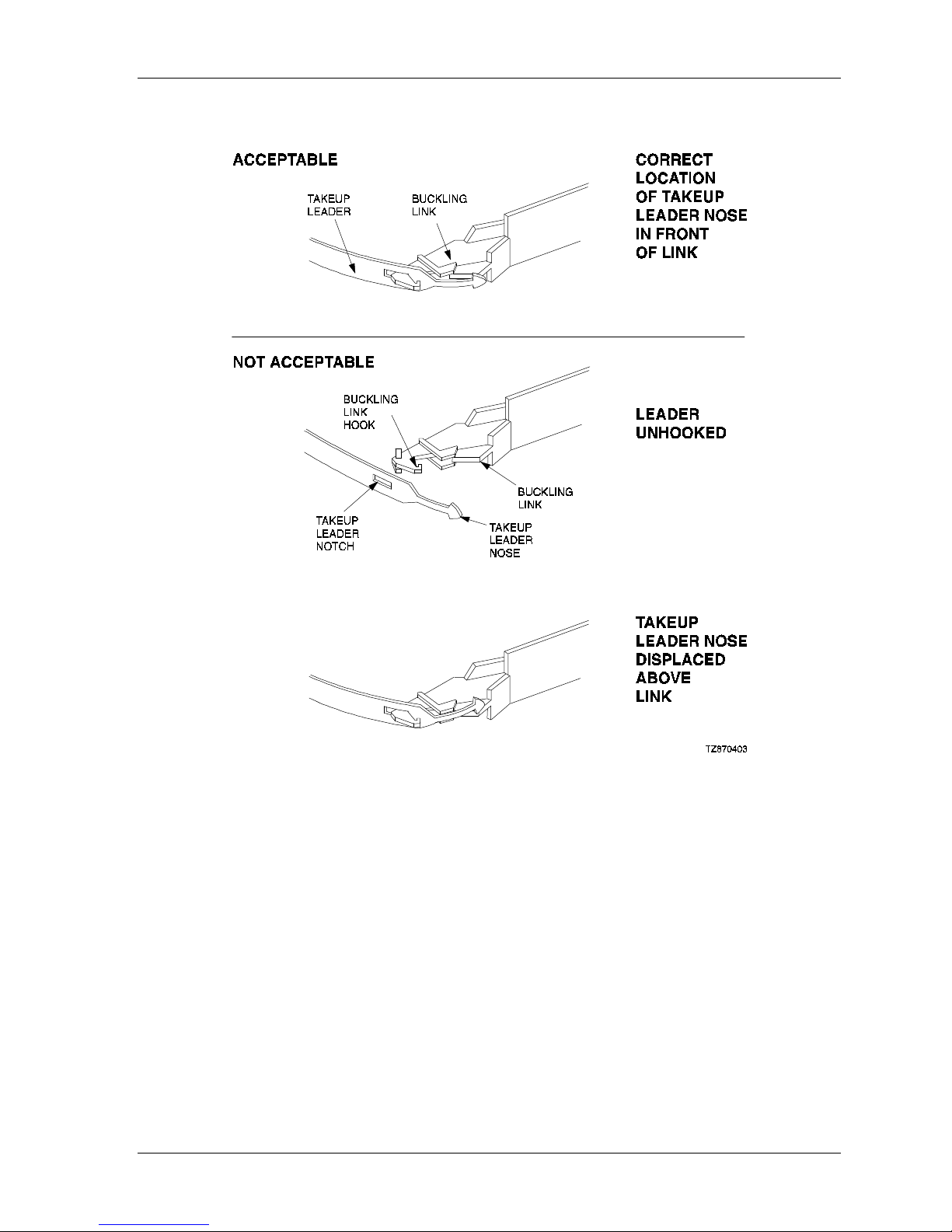
Figure 5–3 Correct and Incorrect Positions of Tape Drive Leader
Chapter 5. Maintenance
Order Number: EK–SM1TB–UG. E01 5–5

StorageWorks DLT 10/20 GB Cartridge Tape Drive
5.5 Troubleshooting
Table 5–2 describes some common drive problems and suggests possible solutions.
Table 5–2 Troubleshooting Table
Symptom Probable Cause Possible Solution
Unable to back up or
copy data to tape.
WRITE PROTECTED
indicator flashes
orange.
TAPE IN USE and WRITE
PROTECTED LEDs flash
rapidly in unison.
Cartridge writeprotected.
No tape in drive.
Excessive tape errors. Perform head cleaning procedure
Dirty heads or bad
media.
1. Set write-protected tab on cartridge
to write-enabled.
2 Insert tape.
(Section 0) . If error repeats, try
another tape.
Eject tape. Perform head cleaning
procedure (Section 0) . If error
repeats, try another tape.
After applying power,
nothing happens. All
indicators off, except
green O
indicator.
Drive not available to
system.
PERATE HANDLE
Drive error, possibly a
hard failure.
No tape loaded. Load tape.
Drive not plugged in. (If
SBB unit, Storage
Expansion Pedestal may
not be plugged in.)
SCSI ID switches set to
incorrect address.
Defective SCSI cable.
Eject tape. Power off and power on the
drive. If error repeats, replace the
drive.
1. Check ac power source.
2. Check SCSI ID switch settings.
3. Ensure power cable is plugged in
and SCSI cable is seated properly.
5–6 Order Number: EK–SM1TB–UG. E01
A
Specifications
This appendix describes the physical, electrical, and environmental specifications for the StorageWorks 10/20GB DLT Cartridge Tape Drive Family , covering both the SWXTL-BA StorageWorks Building Block (SBB) & the
SWXTL-BT Tabletop DLT Cartridge Tape Drive.
Table A–1 10/20-GB DLT Cartridge Tape Drive Specifications
Characteristic Specification(s)
Performance
Read/write speed 120 in/s, streaming
Transfer rate, raw 1.7 MB/s
Transfer rate, user native 1.25 MB/s
Transfer rate, user compressed Over 2.5 MB/s maximum Write
Over 3.0 MB/s maximum Read
Repositioning time (typical) 1.3s
Error rate, detected 1 in 1017 bits read
Error rate, undetected 1 in 1030 bits read (calculated)
Error correction code Custom Reed-Solomon ECC
Drive interface SCSI-2
Passes per cassette tape Over 500,000 passes
Power requirements 120/240 Vac @ 60/50 Hz
Data organization
Recording format 128-track serial serpentine fixed block
Recording density 62,500 bits/in
Track density 256 tracks/in
Data encoding 2,7 RLL
Record size Variable up to 64 KB with 4-KB blocking factor
Data compression algorithm DLZ
Maximum capacity (formatted) 20 GB (per cartridge)
†
†
Assumes a 2:1 compression ratio. (Continued on next page)
Order Number: EK–SM1TB–UG. E01 A–1

StorageWorks DLT 10/20 GB Cartridge Tape Drive
Table A–1 10/20-GB DLT Cartridge Tape Drive Specifications (Continued)
Characteristic Specification(s)
Recording medium:
Tape 0.5 metal particle (MP) tape, 1400 to 1500 Oersted, 0.5
mil thick
Length 1186 ft (usable)
Cartridge CompacTape III 0.5-in tape in a 4.1x4.1x1 in cartridge
Durability 500,000 tape-head passes
Shelf life 10 years minimum @20°C and 40% RH (noncondensing)
Operating environment:
Temperature 10°C to 40°C
Relative humidity 20% to 80% noncondensing
Altitude (maximum) 8,000 ft
Software support
Physical Characteristics
SWXTL-BA SBB Tape
Drive
Height 14.52 cm (5.72 in)
Width 23.49 cm (9.25 in)
Length 33.22 cm (13.08 in)
Weight 7.7 Kg (16.9 lb)
SWXTL-BT Tabletop Tape Drive
Height 13.49 cm (5.31 in)
Width 23.50 cm (9.25 in)
Length 33.22 cm (13.08 in)
Weight 7.7 Kg (16.9 lb)
Refer to Appendix B
A–2 Order Number: EK–SM1TB–UG. E01

B
Product Notes for
™
Windows NT,
This appendix provides information for the system administrator, who should read this appendix before installing and using the 10/20-GB DLT Cartridge Tape Drives (SWXTL-BA or SWXTL-BT) with a host system
operating under the Windows NT, Novell, and MS-DOS operating systems,.
Novell,™ and MS-DOS
B.1 Host SCSI Interface
The 10/20-GB DLT Cartridge Tape Drive devices (SWXTL-BA and SWXTL-BT) use the
standard SCSI-2 command set to interface to the PC-based host system. Therefore, the host
system must be equipped with a SCSI adapter to properly interface the tape drive with the
host. For example, the host SCSI adapter might interface the computer's EISA or PCI bus to
the SCSI-2 port of the tape drive.
A host PC SCSI adapter is normally supplied with a compatible software driver for use with
its operating system. When operating under the Windows NT, Novell, or MS-DOS operating
systems, the software driver must be preloaded in accordance with the SCSI adapter
manufacturer’s installation procedure in order to ensure a proper interface between the 10/20GB DLT Cartridge Tape Drive and the host. In addition, a user-level tape read/write software
program may be required to implement tape support under the Windows NT, Novell, and
MS-DOS environments. There are many commercial software products available that provide
host or network-based functionality (data backup and restore, archiving, data logging, etc.)
for these operating systems.
™
Before purchasing a user-level software product, ensure that the 10/20-GB DLT Cartridge
Tape Drive is supported by that product (see note below). Commercial software vendors
usually publish a supported hardware list, or have telephone technical support personnel that
will answer questions regarding compatibility of a particular tape drive or other storage
devices. When choosing a software product suitable for your application, follow the software
vendor's installation procedure to implement support for your tape drive.
The 10/20-GB DLT Cartridge Tape Drive is functionally equivalent
to the TZ87N (DEC part no.) tape drive. Commercial software
products that support the TZ87N will also support both the
SWXTL-BA SBB and the SWXTL-BT Tabletop devices.
_______________
Novell™ is a trademark of Novell, Inc.
Windows NT™ and MS-DOS™ are trademarks of Microsoft Corporation
Order Number: EK–SM1TB–UG. E01 B–1
NOTE

StorageWorks DLT 10/20-GB Cartridge Tape Drive
Finally, if your host is operating under Novell Netware, Novell, Inc. provides a software
product called "Server Backup" with some of its operating system products. This program
has been found to work well with the SWXTL-BT Tape Drive (used in the tape loaders) and
in the SBB. The SWXTL-BL mini-library autoloader is not supported by this software
product, however.
B–2 Order Number: EK–SM1TB–UG. E01

C
Product Notes for Sun™
This appendix describes how to include the SWXTL cartridge tape drive SBB in a Sun SPARC system
running Solaris™ 2.3 (or later) and SunOS™ 4.1.x. The information covers the installation of the SWXTL
tape drive hardware and configuring the system to communicate with the drive.
C.1 General Information
Densities can only be changed at the beginning of the tape.
Front panel operation will override software control of density and compression settings.
To use software-controlled density selections, the drive must first be placed in
“automatic” mode. To accomplish this, press the D
number of times until only the D
Compression can be enabled or disabled at any time, with the change taking effect
immediately when writing TZ87 density.
ENSITY OVERRIDE light is on.
ENSITY SELECT button the required
C.2 Modifications Required for SunOS 4.1.x
C.2.1 Installation Procedure
NOTES
1. The SWXTL designation in the following procedure is the
StorageWorks product name for "DEC TZ87".
2. In order to support the addition of this device, the
applicable drive information must be supplied in the
/sys/scsi/targets/st_conf.c file. For additional
information, read the man pages for "st".
C.2.1.1 System Modification
Perform the following steps to modify the system for communication with the SWXTL
tape drive:
1. From the command line, type:
cd /sys/scsi/targets
_______________
Sun™, SunOS™ and Solaris™ are trademarks or registered trademarks of Sun Microsystems,
Inc.
Order Number: EK-SM1TB-UG. E01 C–1

StorageWorks DLT 10/20 GB Cartridge Tape Drive
2. Edit the "st_conf.c" file and carefully add the following structure before the entry for
"/* Exabyte 8mm 5GB cartridge */":
/* TZ87 10GB DLT Streaming /w Compression Cartridge tape drive */
{
"DEC TZ87 10GB Cart. DLT Steaming /w Compression", 12 ,
"DEC TZ87",ST_TYPE_DEFAULT, 8192,
(ST_BSF | ST_VARIABLE | ST_LONG_ERASE | ST_KNOWS_EOD),
5000, 5000,
{ 0x17, 0x18, 0x80, 0x81 },
{ 0, 0, 0, 0 }
},
3. Verify that the above entry is added to the st_conf.c file correctly.
Where,
• The first parameter
Compression)
• The second parameter (
(DEC TZ87 10GB Cart. DLT Streaming /w
is the name given to the drive.
12) is the length of the vendor ID provided by the
"inquiry" command.
• The third parameter (
are included between “
• The fourth parameter (
• The fifth parameter (
• The sixth parameter (
| ST_KNOWS_EOD
• The seventh parameter (
• The eighth parameter (
• The ninth parameter (
DEC TZ87) is the vendor ID. (Ensure that five spaces
DEC” and “TZ87” elements.)
ST_TYPE_DEFAULT) is the drive type for the driver.
8192) is the block size in bytes.
ST_BSF | ST_VARIABLE | ST_BSR | ST_LONG_ERASE
) comprises the drive options.
5000) is the maximum number of read retries.
5000) is the maximum number of write retries.
0x17, 0x18, 0x80, 0x81) comprises the density codes
(low é hi) as defined below:
• 0x17 is the vendor-unique density code for the TK85 (2.6 GB).
• 0x18 is the vendor-unique density code for TK86 (6.0 GB).
• 0x80 is the vendor-unique density code for the TK87 native in the uncompressed
mode (10 GB).
• 0x81 is the vendor unique code for the TK87 in the compressed mode (20 GB).
• The tenth parameter (0,0 . . .) is the speed code (not used).
C.2.1.2 Rebuilding of Kernel
After you have edited the "st_conf.c" file and added the above entry, rebuild thekernel
using the standard procedure (for further help, refer to the man pages of the config
command).
C.2.1.3 Installation of tape drive
Install the tape drive into the storage subsystem and power on the workstation. We
recommend that the SWXTL SCSI device address be set to ID 4 or 5.
C–2 Order Number: EK-SM1TB-UG. E01

Appendix C. Product Notes for Sun
NOTE
If your SCSI host adapter is supported by the “probe-scsi”
command, you can use this command at the boot prompt to
verify that the connected device is correctly attached to the
system.
C.2.1.4 Rebooting of system
Reboot the system, using the following command at the boot prompt:
>boot
The system reboots with the newly compiled kernel and creates special files in /dev so
that it can communicate with the SWXTL SBB. Verify that “
DLT Streaming /w Compression
” is displayed as a target when the system is
DEC TZ87 10GB Cart.
booting.
At this time the tape is configured in the /dev directory with "rst" (rewind on close) and
"nrst" (no rewind on close) format. If the entry in the kernel configuration file for the
SWXTL SBB were st4, for example, then "rst" would be "rst4, rst12, rst20, rst28" and
nrst would be"nrst4, nrst12, nrst20, nrst28".
• rst4 and nrst4 correspond to the 0x17 density mode (TK85 format)
• rst12 and nrst12 correspond to the 0x18 density mode (TK86 format)
• rst20 and nrst20 correspond to the 0x80 density mode (TK87 native format)
• rst28 and nrst28 correspond to the 0x81 density mode (TK87, compressed format)
C.2.1.5 Testing the SWXTL SBB
To test the SWXTL drive, back up the “passwd” file to tape using the “tar” command,
as follows:
tar cvf /dev/rst4 /etc/passwd
The system responds with:
a /etc/passwd 1 blocks
Note that depending on the size of the file, a different number of blocks may be reported.
C.2.1.6 Verification
Verify that the “passwd” file was written to tape using the following command:
tar tvf /dev/rst4
The system responds with:
/etc/passwd
The installation and verification procedure is now complete.
Order Number: EK-SM1TB-UG. E01 C–3

StorageWorks DLT 10/20 GB Cartridge Tape Drive
C.2.2 Dump Parameters for the Tape Drive
The parameters that should be used when running the dump utility with the SWXTL tape
drive are:
density: 62500 (BPI)
size: 1200 (1200-foot tape)
blocking factor: 126
Example 1
The following example shows backing up the entire disk partition onto the SWXTL tape
drive:
dump 0dsbf 62500 1200 126 /dev/rst20 /dev/sd0g
For further help, refer to man pages of the dump command.
C.3 Modifications Required for Solaris 2.3 (or later)
C.3.1 Installation Procedure
NOTES
1. The “SWXTL” designation in the following procedure is the
StorageWorks product name for the TZ87 tape drive.
2. I n order to support the addition of this device, drive information must be supplied in the
global properties that apply to each of the targets, or as
properties that are applicable to one target only. The "st
driver" looks for the property called "tape-config-list". For
additional information, read the man page “st”. We recommend here the use of the global properties approach.
/kernel/drv/st.conf
file as
C.3.1.1 System Modification
Perform the following steps to modify the system to communicate with the SWXTL tape
drive:
1. From the command line, type:
cd /kernel/drv
2. Edit the “st.conf” file by adding the following before the first occurrence of
“name=":
# entry for TZ87 tape drive
tape-config-list = "DEC TZ87",
"DEC 10GB Cart. DLT Streaming /w Compression”, “TZ87-data”;
TZ87-data = 1,0x36,8192,0x1639,4,0x17,0x18,0x80,0x81,3;
C–4 Order Number: EK-SM1TB-UG. E01

where:
In the “tape-config-list” parameter:
Appendix C. Product Notes for Sun
• The first parameter (
DEC TZ87) is the parameter returned by the SWXTL
SBB on a SCSI inquiry command. (There should be five spaces between “
and “
TZ87” elements.)
• The second parameter (DEC 10GB Cart. DLT Streaming /w
compression) is a nickname for the SWXTL drive.
• The third parameter is defined as follows:
In the “TZ87-data” string:
– The first parameter (1) is the revision level of the software and is set to 1. The
first parameter (1) is the revision level of the software and is set to 1.
– The second parameter (
(This is defined
in /usr/include/sys/mtio.h.)
0x36) is the tape type, specifying “other” tape drive.
– The third parameter (8192) is the block size in bytes.
– The fourth parameter (
0x1639) defines the options selected. The 0x1639
value represents the following options:
ST_VARIABLE = 0x0001
ST_BSF = 0x0008
ST_BSR = 0x0010
ST_LONG_ERASE = 0x0020
ST_KNOWS_EOD = 0x0200
ST_UNLOADABLE = 0x0400
ST_LONG TIMEOUTS = 0x1000
DEC”
– The fifth parameter (
4) defines the number of densities. The maximum
definable number of densities is 4.*
– The sixth parameter (
0x17) is the vendor-unique density code for the TK85
(2.6 GB).
– The seventh parameter (
0x18) is the vendor-unique density code for TK86
(6.0 GB).
– The eighth parameter (
0x80) is the vendor-unique density code for the TK87
native (10 GB).
– The ninth parameter (
0x81) is the default density code for the TK87
compressed mode.
– The last parameter in the SWXTL-data parameter is the default density 3,
TK87 in the compressed mode.
_______________
*This maximum definable number of densities is a Sun Operating System limitation.
Order Number: EK-SM1TB-UG. E01 C–5

StorageWorks DLT 10/20 GB Cartridge Tape Drive
C.3.1.2 System Shutdown
After you have edited the “st.conf” file, shut down the system as follows:
sync
cd /
shutdown -i0 -g0 -y
C.3.1.3 Installation of the Tape Drive
Install the tape drive into the storage subsystem and power on the workstation. We
recommend that the SWXTL SCSI device address be set to ID 4 or 5.
If your SCSI host adapter is supported by the “probe-scsi”
command, then you can use this command at the boot prompt
to verify that the connected device is correctly attached t o the
system.
C.3.1.4 Rebooting of System
Reboot the system using the following command at the boot prompt:
NOTE
>boot -rv
Note that the switch "r" forces the kernel to be re-configured, and switch "v" enables a
display of the system configuration at boot time.
The system compiles the kernel and creates special files in /dev so that it can
communicate with the SWXTL SBB. Since you booted the system using the verbose
switch, the system displays all of its SCSI targets. Verify that “DEC 10GB Cart.
DLT Streaming /w Compression” is displayed as a target when the system is
booting.
At this time, the tape drive is configured in the /dev directory in two ways: rmt format,
and rst format.
“rmt” format
In this format, the drive is configured with various options. For further explanations, see
the man pages on “st” (the modes are x, xl, xm, xh, xc, and xu, where x is the rmt
number).
• Options x, xu, and xc, correspond to the 0x81, (TK87, compressed) density mode.
• Option xl, corresponds to the 0x17 (TK85) density mode.
• Option xm corresponds to 0x18 (TK86) density mode.
• Option xh corresponds to 0x80 (TK87, native) density mode.
• Option b associates with the BSD behavior and is for backward compatibility on all
of the above options. For further information, refer to the man pages of “mtio”.
• The n option provides access to the device with no rewind, similar to nrst (below),
and is also applicable to all of the above options.
C–6 Order Number: EK-SM1TB-UG. E01

Appendix C. Product Notes for Sun
“rst” format
Special files “rst” (rewind on close) and “nrst” (no rewind on close) are also built and
reside in the /dev directory. For example, if the SCSI target ID for the SWXTL drive is 4
and
the drive is connected to the native SCSI bus, then “rst” will be “rst4, rst12, rst20,
and rst28” and nrst will be “nrst4, nrst12, nrst20, and nrst28”.
• rst4 and nrst4 correspond to the 0x17 density mode (TK85 format)
• rst12 and nrst12 correspond to the 0x18 density mode (TK86 format)
• rst20 and nrst20 correspond to the 0x80 density mode (TK87, native format)
• rst28 and nrst28 correspond to the 0x81 density mode (TK87, compressed format)
C.3.1.5 Test
To test the SWXTL drive, back up the “passwd” file to tape using the “tar” command,
as follows:
tar cvf /dev/rst4 /etc/passwd
The system responds with:
a /etc/passwd 1 blocks
Note that, depending on the size of the file, a different number of blocks may be
reported.
C.3.1.6 Verification
Verify that the “passwd” file was saved to tape using the following command:
tar tvf /dev/rst4
The system responds with
/etc/passwd
The installation and verification procedure is now complete.
C.3.2 Running Sun Diagnostics (Optional)
The diagnostic exerciser provided with the Sun operating system (“sundiag”) does not
support the generic DLT tape drive configuration. In order to run “sundiag”, you must
modify the st.conf file in the /kernel/drv directory. Change the “tape type” in
the SWXTL-data parameter from 0x36 (generic other type of drive) to 0x29 (Exabyte
8500 8mm cartridge) and re-boot the system with the “boot -r” option. You can now
run “sundiag” when the system is up and running.
CAUTION
Remember to change the “tape type” back to 0x36 and
reboot the system with the “boot -r” option after running
“sundiag”.
Order Number: EK-SM1TB-UG. E01 C–7

StorageWorks DLT 10/20 GB Cartridge Tape Drive
C.3.3 Dump Parameters for the Tape Drive
The parameters that should be used when running the ufsdump utility with the SWXTL
tape drive are as follows:
density (d) = 62500 (BPI)
blocking factor = 126
Example,
The following parameter is an example of how to back up the entire disk partition
(/dev/rdsk/c0t3d0s6) onto the SWXTL tape drive:
ufsdump 0dbfo 62500 126 /dev/rmt/2 /dev/rdsk/c0t3d0s6
C–8 Order Number: EK-SM1TB-UG. E01

D
Product Notes for IBM™ RS/6000
This appendix provides information for the system administrator. It should be read before installing and using the
SWXTL-BA tape drive SBB with a host system with the AIX 3.2.5 (or later) operating system.
D.1 Modifications Required to Operate the SWXTL-BA with AIX 3.2.5 (or later)
After the SWXTL-BA tape drive has been properly attached to the SCSI bus, install the device
using "smit" or by executing specific commands while logged into the root account. Section
D.1.1 below describes how to install the tape drive using the fast-path command (smit dev).
Section D.1.2 describes how to install the device using the command-line interface.
D.1.1 Installing the SWXTL-BA Using the SMIT Command
While the SWXTL-BA can operate with a variable block size (0) or the conventional
values of 512 or 1024, for best performance us a block sixe of at least 10240.
From the command line, type:
# smit dev
Select menu entry "Configure the devices you have added after the IPL".
Select menu entry "Change/show the characteristics".
a) Select the entry that matches the controller and target ID of your installation.
Example: rmt1 available 00–03–00–50 other SCSI tape drive
where 3 is the SCSI controller number and 5 is the SCSI target ID
b) On the menu, change the settings of the "BLOCK size", "DENSITY setting #1", and
"DENSITY setting #2".
Set “BLOCK size” to 10240.
Set “DENSITY setting #1” to 129.
Set “DENSITY setting #2” to 128.
Density codes are listed in Section D.1.2 below.
c) Accept the changes.
Order Number: EK–SMITB–UG. E01 D–1

StorageWorks DLT 10/20-GB Cartridge Tape Drive
D.1.2 Installing the SWXTL-BA Using Command-Line Interface
From the command line, type:
# cfgmgr
To determine which rmt has been added, type:
# lsdev –Cc tape
Example:
# lsdev –Cc tape
Name Status Location Description
rmt0 Available 00–03–00–50 Other SCSI Tape Drive
Next, type:
# chdev –l <rmt*> –a density_set_1=129 –a density_set_2=128
Finally, type the following:
# chdev –l <rmt*> –a block_size=<SIZE>
Example:
# chdev –l rmt0 –a block_size=10240
rmt0 changed
where,
<rmt*> is the tape drive added as shown by the lsdev command.
<SIZE> is the fixed block size (0 = variable, 10240 is suggested).
Density code “129” specifies compressed format while “128” specifies uncompressed format. In
rare cases, other density codes may be useful. The legal values for the density code are listed in
the following table:
Density Code Meaning
10 TK50 – 6667 bpi FMF serial cartridge tape X3B5/86-199 (read-only)
22 TK70 – 10000 bpi FMF serial cartridge tape X3.193-1990 (read-only)
23 TK85 – 42500 bpi FMF serial cartridge tape X3B5/91-1174, 2.6 GB
24 TK86 – Same as TK85 except with 56 track pairs versus 24, 6.0 GB
25 TK87 – 62500 bpi, 64 track pairs, serial cartridge tape, 10 GB (native)
127 No change from previous density (Mode Select)
129 TK87 format, compression DISABLED
128 TK87 format, compression ENABLED
D
2
Order Number: EK–SM1TB–UG. E01

Appendix D. Product Notes for IBM RS/6000
The files that are created are:
Tape Drive Special File Characteristics
Special File Name Rewind-on-Close Retention-on Open Bytes-per-Inch
/dev/rmt*
/dev/rmt*.1
/dev/rmt*.2
/dev/rmt*.3
/dev/rmt*.4
/dev/rmt*.5
/dev/rmt*.6
/dev/rmt*.7
Yes No Density Setting # 1
No No Density Setting # 1
Yes Yes Density Setting # 1
No Yes Density Setting # 1
Yes No Density Setting # 2
No No Density Setting # 2
Yes Yes Density Setting # 2
No Yes Density Setting # 2
NOTES
1. The suggested values of
compressed and uncompressed format respectively. The only use
of uncompressed format is to determine the relative effectiveness
of the compressed mode.
2. The
3. IBM-supplied tape drives default to a block size of 1024 while tape
density value
TK70, TK85, and TK86 cartridges.
drives from other manufacturers default to a block size of 512.
StorageWorks recommends changing the block size of the SWXTLAA to be compatible with the IBM-supplied drives. However, for
some uses such as making bootable tapes or transferring tapes
between host systems, a value of 512 or 0 (variable size) may be
needed.
can be useful in reading tapes on earlier TK50,
density setting #1
and #2 are for
Order Number: EK–SMITB–UG. E01 D–3


E
Product Notes for Hewlett-Packard
This appendix describes how to include the tape drive in an HP 9000 Series 700 system running HP-UX 9.05 or
10.00 and an HP 9000 Series 800 running HP-UX 9.04 or 10.00. The information covers configuration of the
host system to communicate with the tape drive.
E.1 General Information
If the necessary drivers are not already built into your existing kernel, you will need to
rebuild your kernel.
When using the dump utility, you must supply the correct density code and tape length size
for dump to use in its calculations. Refer to Section E.6 for details. We recommend a value
of 126 for the blocking factor parameter.
For this device to be recognized and operational on the S800 servers, it personality was
changed to that of an EXABYTE 8505. Ensure you have the SWHTL part number, not the
SWXTL one.
E.2 Modifications Required
E.2.1 Installation Procedure
The “EXABYTE EXB-8505” designation in the following procedure
is the StorageWorks internal name of the SWHTL Part number.
The "DEC TZ87" designation in the following procedure is the
StorageWorks internal name for the SWXTL part number.
E.2.1.1 Installation of Tape Drive
Install the tape drive into the StorageWorks enclosure and power-on the workstation. Ensure
that the address of the tape drive does not conflict with the address of any other device on
that SCSI bus.
E.2.1.2 System Modification
Enter the System Administration Manager (SAM) as superuser. From the first-level menu,
choose Peripheral Devices. From the second-level menu, choose Tape Drives. The
system’s hardware will be scanned, and the “available tape drives” window will identify the
tape drive as a SCSI Tape Drive (HP-UX 9.05, 9.04) or as a “EXB-8505 5 GB 8mm Tape
Drive” (HP-UX 10.00) for the SWHTL, and as a “DEC TZ87” (HP-UX 10.00) for the
SWXTL with the appropriate hardware path. Highlight that selection and then pull down the
NOTES
Order Number: EK–SM1TB–UG. E01 E–1

StorageWorks DLT 10/20 GB Cartridge Tape Drive
Actions menu and select the Add function. The program at this time will check the kernel to
determine if the necessary drivers are built in, displaying the results.
If necessary, the program will rebuild the kernel. If this occurs, you will have to reboot the
system in order to use the tape drive. For further information on adding tape devices, refer to
Hewlett-Packard’s Installing Peripherals manual, P/N B2355-40041.
E.3 Series 700 System Device Files
The System Administration Manager program automatically creates the appropriate device
files and places them in the /dev/rmt directory, when adding the device through SAM.
Additionally, the device files are created automatically upon system initialization.
E.3.1 HP–UX 9.05
The following naming convention is used for the tape drive SBB, as shown in the examples
listed below:
/dev/rmt/c#d#[hlmc][n][b]
where:
c# specifies the controller designation, which may contain either two or
three characters, specifies the following:
where # is sc[f], in accordance with the following:
s is the system bus module:
2 = core I/O (the default)
4 = EISA SCSI
c is the slot number:
0 for core I/O
n for EISA, the value is determined by the slot number as reported
by the H/W path reported by “ioscan.”
f is the function number. This value identifies the location on the core I/O
bus. For the SCSI interface, the value is 1. If you are using the EISA
SCSI interface, the f value is 0.
d# designates the SCSI address of the tape drive, where # here identifies a
number value.
h/l/m/c specifies density, with h meaning high density, l meaning low density,
m meaning standard DDS format, and c meaning data compression.
1
n specifies no rewind on close.
b specifies Berkeley behavior.
For additional information about magnetic tape operation, refer to mt(7) of the
manual (P/N B 2355-90033) or the Man pages.
_______________
1
The
h, l, and m device designations all yield the same result. The c device designation enables
compression.
E–2 Order Number: EK–SM1TB–UG. E01
HP-UX Reference

Appendix E. Product Notes for Hewlett-Packard
Examples
For a tape drive SBB installed in slot location 4 of the StorageWorks SWXSE-02 expansion
enclosure connected to the main (core) SCSI bus, the following device files would be
produced in the directory /dev/rmt:
c201d4c c201d4l c201d4cb c201d4lb
c201d4cn c201d4ln c201d4cnb c201d4lnb
c201d4h c201d4m c201d4hb c201d4mb
c201d4hn c201d4mn c201d4hnb c201d4mnb
For a tape drive SBB installed in slot location 4 of the StorageWorks SWXSE-02 expansion
enclosure connected to a SCSI adapter in EISA slot 1, the following device files would be
produced in the directory /dev/rmt:
c410d4c c410d4l c410d4cb c410d4lb
c410d4cn c410d4ln c410d4cnb c410d4lnb
c410d4h c410d4m c410d4hb c410d4mb
c410d4hn c410d4mn c410d4hnb c410d4mnb
E.3.2 HP–UX 10.00
The following naming convention is used on systems which support long filenames for the
DLT format tape drive, as shown in the examples below:
/dev/rmt/c#t#d#BEST[n][b]
where:
c# specifies the instance number of the interface card
t# specifies the SCDI address of the tape drive
d# specifies the device number (LUN) at the SCSI address
BEST specifies the highest capacity density, which for this device is the TK87
compressed format
n specifies no rewind on close
b specifies Berkeley behavior
Examples:
For a tape drive SBB installed in slot location 4 of the StorageWorks SWXSE-02 expansion
enclosure connected to the main (core) SCSI bus, the following device files would be
produced in the directory /dev/rmt:
c0t40BEST c0t40BESTnb
c0t4d0BESTb c0t40BESTnb
For systems which do not support long file names, the following device naming conventions
is used:
#m #mb #mn #mnb
Order Number: EK–SM1TB–UG. E01 E–3

StorageWorks DLT 10/20 GB Cartridge Tape Drive
where:
# specifies an arbitrary number to distinguish this tape drive from others
N specifies no rewind on close
b specifies Berkeley behavior
This tape drive will read both TK85 (2.6 MB) and TK86 (6.0 MB)
densities but will not write these densities to the above device files.
Use the front panel override button to write these densities.
To list the device files associated with each device, issue the command “ioscan -f -n/more”.
E.4 Series 800 System Device Files
The System Administration Manager program automatically creates the appropriate device
files and places them in the /dev/rmt directory when adding the device through SAM.
Additionally, the device files are created automatically upon system initialization..
E.4.1 HP–UX 9.04
NOTE
The following naming convention is used for the tape drive SBB, as shown in the examples
listed below:
/dev/rmt/lu[l|m|h[c]][n][b]
where:
lu specifies the logical unit as reported for the tape drive using the “ioscan -
f” commmand
h/l/m/c specifies density, with h meaning high density, l meaning low density,
m meaning standard DDS format, and c meaning data compression
1
1
n specifies no rewind on close
b specifies Berkeley behavior
For additional information about DDS tapes, refer to mt(7) of the HP-UX Reference manual
(P/N B 2355-90033).
Example
If you were to install a tape drive SBB in the StorageWorks SWXSE-02 expansion
enclosure, the following device files would be produced for the device having a logical unit
number of 4 in the directory /dev/rmt:
4hc 4l 4hcb 4lb
4hnc 4ln 4hncb 4lnb
4h 4m 4hb 4mb
4hn 4mn 4hnb 4mnb
1
The h, l, and m device designations all yield the same result. To disable compression, use the front panel
override button and select the desired density
E–4 Order Number: EK–SM1TB–UG. E01

Appendix E. Product Notes for Hewlett-Packard
E.4.2 HP-UX 10.00
The following naming convention is used on systems which support long filenames for the
DLT format tape drive SBB, as shown in the examples below:
/dev/rmt/c#t#d#BEST[n][b]
where:
c# specifies the instance number of the interface card
t# specifies the SCDI address of the tape drive
d# specifies the device number (LUN) at the SCSI address
BEST specifies the highest capacity density, which for this device is the TK87
compressed format
n specifies no rewind on close
b specifies Berkeley behavior
Examples:
For a tape drive SBB installed in slot location 4 of the StorageWorks SWXSE-02 expansion
enclosure connected to the main (core) SCSI bus, the following device files would be
produced in the directory /dev/rmt:
c0t40BEST c0t40BESTnb
c0t4d0BESTb c0t40BESTnb
For systems which do not support long file names, the following device naming conventions
is used:
#m #mb #mn #mnb
where:
# specifies an arbitrary number to distinguish this tape drive from others
N specifies no rewind on close
b specifies Berkeley behavior
This tape drive will read both TK85 (2.6 MB) and TK86 (6.0 MB)
densities but will not write these densities to the above device files.
Use the front panel override button to write these densities.
To list the device files associated with each device, issue the command “ioscan -f -n/more”.
E.5 Testing the Tape Drive
NOTE
To test the tape drive, back up the “passwd” file to tape using the “tar” command, as follows
(assuming that you installed the drive in accordance with the preceding example):
tar cvf /dev/rmt/4h /etc/passwd
Order Number: EK–SM1TB–UG. E01 E–5

StorageWorks DLT 10/20 GB Cartridge Tape Drive
The system responds with something similar to the following:
a /etc/passwd 1 blocks
Note that depending on the size of the file, a different number of blocks may be reported.
E.5.1 Verification
Use the following command to verify that the “passwd” file was written to tape:
(use the correct device filename for the platform and operating system in use)
tar tvf /dev/rmt/c201d4h
The system responds with something similar to the following:
rw-r--r-- 0/10 535 Mar 23 16:31 1994 /etc/passwd
The installation and verification procedure is now complete.
E.6 Dump Parameters for the Tape Drive
The parameters that should be used when running the dump utility with the tape drive are:
density = 62500 (for DDS1 or DDS2 tapes)
size = 1200 (for 1200 foot tape)
blocking factor = 126 (recommended)
Example:
The following example shows the command for backing up an entire disk partition onto the
tape drive, using a 120-meter tape:
(use the correct device filename for the platform and operating system in use)
dump 0dsbf 62500 1200 126 /dev/rmt/c201d4h /dev/dsk/c202d6S0
For further help, refer to man pages of the dump command.
E–6 Order Number: EK–SM1TB–UG. E01

Reader’s Comments
Manual Order Number:
EK–SM1TB–UG. E01
DLT 10/20-GB Cartridge Tape Drive
–StorageWorks Building Block (SWXTL-BA) / –Tabletop Tape Drive (SWXTL-BT)
Digital is committed to providing the best possible products and services. Since our manuals are important
components of our products, we value your comments, corrections, and suggestions for improvements. Please
take a few minutes to fill out and return this form, attaching additional sheets, if needed. Thank you.
Manual Rating Excellent Good Fair Poor
Accuracy (correct presentation of facts) [ ] [ ] [ ] [ ]
Completeness (adequate information) [ ] [ ] [ ] [ ]
Clarity (easy to understand) [ ] [ ] [ ] [ ]
Organization (logical sequence of information) [ ] [ ] [ ] [ ]
Layout (easy to follow subject matter) [ ] [ ] [ ] [ ]
Indexing (easy to locate desired information) [ ] [ ] [ ] [ ]
Errors Noted (please include page, paragraph, table or figure number)
Most-Liked Features
Least-Liked Features
Suggestions for Improvement
Return Address:
Digital Equipment Corporation
Customer Research
Response Center
ATTN: Nan Andrews Amish
334 South Street, SHR3-2/S27
Shrewsbury, MA 01545
Name Phone
Title
Company
Street Address
Mail Stop
City State ZIP
Country (if other than USA)

 Loading...