


RA7000 and ESA10000
Storage Subsystems
User's Guide
EK–SMCPP–UG. A01
Digital Equipment Corporation
Maynard, Massachusetts

First Edition, July 1997
The information in this document is subject to change without notice and should not be
construed as a commitment by Digital Equipment Corporation. Digital Equipment
Corporation assumes no responsibility for any errors that may appear in this document.
Restricted Rights: Use, duplication, or disclosure by the U.S. Government is subject to
restrictions as set forth in subparagraph (c) (1) (ii) of the Rights in Technical Data and
Computer Software clause at DFARS 252.227-7013.
Digital Equipment Corporation does not give a warranty of any kind regarding the
fitness or applicability of the information content for a particular purpose. The user
assumes all responsibility for understanding the interrelationships of this enclosed
information with other affected software or system products.
The disclosure of this information does not grant to the user a license under any patents,
pending patents, trademarks, or copyrights or other rights of Digital Equipment
Corporation, or of any third party.
FCC Notice: This equipment generates, uses, and may emit radio frequency energy.
The equipment has been type tested and found to comply with the limits for a Class A
computing device pursuant to Subpart J of Part 15 of FCC Rules, which are designed to
provide reasonable protection against such radio frequency interference when operated
in a commercial environment. Any changes or modifications made to this equipment
may void the user's authority to operate the equipment. Operation of this equipment in a
residential area may cause interference, in which case the user, at his own expense, may
be required to take measures to correct the interference.
UNIX is a registered trademark in the United States and other countries, licensed
exclusively through X/Open Company, Ltd.
Microsoft is a registered trademark and Windows and Windows NT are trademarks of
Microsoft Corporation.
All other trademarks and registered trademarks are the property of their respective
owners.
DIGITAL, the DIGITAL logo, and StorageWorks are trademarks of Digital Equipment
Corporation.
Copyright © Digital Equipment Corporation 1997 All Rights Reserved
Printed in U. S. A

Contents
Revision Record
About This Guide
........................................................................................................ ix
...................................................................................................... xi
1 Product Description
1.1 Subsystem Overview................................................................................................. 1–1
1.2 Major Components.................................................................................................... 1–4
1.2.1 HSZ70 RAID Array Controllers............................................................................. 1–5
1.2.2 SCSI Buses............................................................................................................ 1–6
1.2.3 Single-Ended I/O Module (SE I/O)........................................................................1–7
1.2.3.1 Expanding the UltraSCSI Bus..............................................................................1–8
1.2.3.2 Controlling the Internal SCSI Bus....................................................................... 1–9
1.2.3.3 Controlling the External SCSI Bus...................................................................... 1–9
1.2.3.4 Controlling the Fault Bus.................................................................................... 1–9
1.2.3.5 “Warm Swapping” I/O Modules and Cables ....................................................... 1–9
1.3 Error Detection and Reporting.................................................................................1–10
1.3.1 Fault Bus............................................................................................................. 1–10
1.3.2 Environmental Monitor Unit (EMU).................................................................... 1–11
1.3.2.1 Controller Status............................................................................................... 1–11
1.3.2.2 I/O Module Status............................................................................................. 1–12
1.3.2.3 Enclosure Configuration Information................................................................ 1–12
1.3.2.4 EMU Front Panel.............................................................................................. 1–13
1.3.3 Power Verification and Addressing (PVA) Module.............................................. 1–15
1.3.3.1 Monitoring Power Supply Operation................................................................. 1–16
1.3.3.2 Master Enclosure Controlled Power Shutdown ................................................. 1–17
1.3.3.3 Expansion Enclosure Initiated Power Shutdown................................................ 1–18
1.3.3.4 PVA UPS (Uninterruptable Power Supply) Options.......................................... 1–19
1.4 Storage Device SBBs............................................................................................... 1–19
1.5 Power Configuration................................................................................................ 1–20
1.5.1 AC Power Entry Controllers................................................................................ 1–20
1.6 Power Supply SBBs................................................................................................. 1–22
1.7 Standard (4 + 1) Power Configuration ..................................................................... 1–23
1.8 Redundant (4 + 4) Power Configuration................................................................... 1–25
1.9 ECB SBBs............................................................................................................... 1–26
EK–SMCPP–UG. A01 iii

RA7000 nd ESA10000 Storage Subsystems
1 Product Description (continued)
1.10 Subsystem Cooling................................................................................................ 1–28
1.11 Setting the PVA SCSI Address.............................................................................. 1–30
1.11.1 DIGITAL Supported Master PVA Address........................................................ 1–31
1.11.2 DIGITAL Supported Expansion PVA Addresses................................................ 1–32
1.11.3 Non-Supported PVA SCSI Bus Addresses ......................................................... 1–32
2 Unpacking and Installation for the RA7000 and ESA10000 Storage Subsystems
2.1 Installing the RA7000................................................................................................ 2–1
2.1.1 Site Preparation..................................................................................................... 2–2
2.1.2 Unpacking the RA7000 Subsystem Enclosure........................................................ 2–2
2.1.3 Removing the RA7000 from the Pallet ..................................................................2–3
2.1.4 Placing the RA7000 Storage Enclosure.................................................................. 2–5
2.1.5 Connecting the Enclosure to the Host .................................................................... 2–5
2.2 Installing the ESA10000............................................................................................ 2–6
2.2.1 Site Preparation..................................................................................................... 2–6
2.2.2 Unpacking the ESA10000 Subsystem Enclosure....................................................2–7
2.2.3 Removing the ESA10000 from the Pallet............................................................... 2–9
2.2.4 Moving the ESA10000 to It’s Designated Site..................................................... 2–13
2.2.5 Joining Adjacent ESA10000’s ............................................................................. 2–13
2.2.6 Leveling the Cabinet............................................................................................ 2–16
2.3 Installing Additional Components ........................................................................... 2–16
2.3.1 Installing the BA370 Rack-Mountable Enclosure................................................. 2–16
2.4 Cabling a Master Enclosure to an Expansion Enclosure(s) ....................................... 2–24
2.4.1 Cabling Sequence................................................................................................ 2–24
2.4.2 Attaching the SE I/O Cables................................................................................ 2–24
2.4.2.1 Single Expansion Unit...................................................................................... 2–25
2.4.2.2 Two Expansion Units........................................................................................ 2–26
2.4.3 Attaching the EMU Communications Cable......................................................... 2–27
2.4.4 Setting the PVA Addresses.................................................................................. 2–28
2.5 Connecting SCSI Bus Cables to the ESA10000........................................................ 2–30
2.6 Installing SBBs........................................................................................................ 2–32
2.6.1 Installing SBB Disk Drives.................................................................................. 2–32
2.6.2 Installing SBB Power Supplies............................................................................ 2–34
2.6.3 Installing the AC Input Power Controller............................................................. 2–35
2.6.4 Installing the External Cache Battery (ECB) ........................................................ 2–36
3 Configuring the Storage Cabinet
3.1 Configuring the EMU................................................................................................3–1
3.1.1 Connecting the EMU Communications Bus........................................................... 3–2
3.1.2 Setting the Temperature Sensors............................................................................ 3–2
3.1.3 Setting the Blower Speed Control.......................................................................... 3–3
3.1.4 Alarm Control Switch............................................................................................ 3–4
iv EK–SMCPP–UG. A01

4 Error Analysis and Fault Isolation
4.1 Storage Subsystem Error Reporting........................................................................... 4–1
4.2 EMU Error and Fault Status Reporting...................................................................... 4–4
4.3 EMU Subsystem Status LEDs.................................................................................... 4–5
4.3.1 EMU System Fault Code Displays......................................................................... 4–8
4.3.2 Controlled Power Shut Down............................................................................... 4–13
4.3.3 Automatic Shut Down ......................................................................................... 4–13
4.3.4 User-Initiated Master Enclosure Shut Down........................................................ 4–14
4.3.5 User-Initiated Expansion Enclosure Shut Down................................................... 4–15
4.4 Controller Error Conditions..................................................................................... 4–16
4.5 Storage Device Fault Notification............................................................................ 4–16
4.6 Power Supply Fault Notification.............................................................................. 4–18
4.7 I/O Module Error Reporting .................................................................................... 4–19
4.7.1 Incompatible I/O Modules................................................................................... 4–19
4.7.2 No I/O Module Installed...................................................................................... 4–19
4.7.3 TERMPOWER Errors.......................................................................................... 4–19
5 Replacing Components
5.1 Replacing a Controller or Cache Module................................................................... 5–1
5.1.1 Tools Required...................................................................................................... 5–1
5.1.2 Precautions............................................................................................................5–1
5.2 Preparing Your Host System...................................................................................... 5–2
5.2.1 Backup the System................................................................................................ 5–2
5.2.2 Shut Down the System........................................................................................... 5–2
5.3 Controller Module Removal...................................................................................... 5–2
5.4 Cache Module Removal............................................................................................. 5–5
5.5 Replacing an SBB Storage Device............................................................................. 5–6
5.5.1 Replacement Method.............................................................................................5–7
5.5.2 Before You Replace a Storage SBB....................................................................... 5–7
5.5.3 SBB Replacement.................................................................................................. 5–7
5.6 Replacing Storage Subsystem Blowers...................................................................... 5–9
5.7 Replacing a Power Supply SBB............................................................................... 5–11
5.8 Replacing a Power Entry Controller......................................................................... 5–12
5.9 Replacing an EMU.................................................................................................. 5–13
5.10 Replacing a PVA................................................................................................... 5–14
5.11 FRU Parts List....................................................................................................... 5–15
Contents
Reader Comment Form
EK–SMCPP–UG. A01 v
...................................................................Inside Back Cover

RA7000 nd ESA10000 Storage Subsystems
Figures
Figure 1–1 BA370 Rack Mountable Enclosure............................................................... 1–1
Figure 1–2 RAID 7000 Enclosure................................................................................... 1–2
Figure 1–3A ESA10000 Storage Cabinet (Shown with two BA370 Rack Mountable
Enclosures in one cabinet)...................................................................................... 1–2
Figure 1–3B ESA10000 Storage Cabinet (Shown with three BA370 Rack Mountable
Enclosures in two cabinets).................................................................................... 1–3
Figure 1–4 Configured BA370 Rack Mountable Unit Major Components....................... 1–4
Figure 1–5 HSZ70 Controller and Cache Modules.......................................................... 1–5
Figure 1–6 SCSI Buses................................................................................................... 1–6
Figure 1–7 Single-Ended I/O Module Location .............................................................. 1–7
Figure 1–8 Single-Ended I/O Module.............................................................................1–8
Figure 1–9 Environmental Monitor Unit (EMU)........................................................... 1–13
Figure 1–10 Power Verification and Addressing (PVA) Module................................... 1–15
Figure 1–11 Disk Drive SBB........................................................................................ 1–19
Figure 1–12 AC Power Entry Controller....................................................................... 1–21
Figure 1–13 Typical Shelf Power Supply SBB.............................................................. 1–22
Figure 1–14 Standard Power Configuration (4 + 1)....................................................... 1–24
Figure 1–15 Redundant Power Configuration (4 + 4).................................................... 1–25
Figure 1–16 External Cache Battery (ECB) SBB.......................................................... 1–26
Figure 1–17 Cache-to ECB-Connection........................................................................ 1–28
Figure 1–18 Dual Speed Blower Locations................................................................... 1–29
Figure 1–19 Enclosure SCSI Address Switch................................................................ 1–30
Figure 1–20 Enclosure SCSI Bus Addresses for all SBB Device IDs............................ 1–31
Figure 2–1 RA7000 Minimum Installation Clearance Measurements.............................. 2–1
Figure 2–2 Unpacking the RA7000 Storage Enclosure.................................................... 2–3
Figure 2–3 Installation of Ramp on Shipping Pallet........................................................ 2–4
Figure 2–4 Minimum Installation Clearance Measurements ........................................... 2–6
Figure 2–5 Shipping Container Contents ........................................................................ 2–7
Figure 2–6 Shipping Pallet Ramp Installation............................................................... 2–10
Figure 2–7 Shipping Bolts and Brackets....................................................................... 2–11
Figure 2–8 Removing the Cabinet from the Pallet ....................................................... 2–12
Figure 2–9 Leveler Foot Adjustment............................................................................ 2–16
Figure 2–10 Mounting Rail Orientation........................................................................ 2–18
Figure 2–11 Rail Installation into Cabinet.................................................................... 2–19
vi EK–SMCPP–UG. A01

Figures (continued)
Figure 2–12 ECB Position............................................................................................ 2–20
Figure 2–13 Installing ECB Y-Cables........................................................................... 2–20
Figure 2–14 Attaching Mounting Brackets to the BA370.............................................. 2–21
Figure 2–15 SE I/O Port Identification......................................................................... 2–24
Figure 2–16 SE I/O Port Wiring (One Expansion Unit) ................................................ 2–25
Figure 2–17 SE I/O Connections for Two Expansion Units........................................... 2–26
Figure 2–18 EMU Front Panel...................................................................................... 2–27
Figure 2–19 Multiple EMUs Connected Together......................................................... 2–27
Figure 2–20 PVA Module Front Panel.......................................................................... 2–28
Figure 2–21 Expansion Enclosure SCSI Bus Addresses................................................ 2–29
Figure 2–22 SCSI Bus Cabling for the ESA10000........................................................ 2–31
Figure 2-23 Installing Power Supply SBB (4+4 Shown) ............................................... 2–34
Figure 2–24 Installing the External Cache Batteries ..................................................... 2–36
Figure 4–1 Storage Subsystem Status LEDs ................................................................... 4–2
Figure 4–2 EMU Front Panel Layout.............................................................................. 4–4
Figure 4–3 Typical Controller OCP Display................................................................. 4–16
Figure 4–4 Storage SBB LEDs..................................................................................... 4–17
Figure 4–5 Power Supply SBB Status LEDs................................................................. 4–18
Figure 4–6 I/O Module LEDs....................................................................................... 4–20
Figure 5–1 HSZ70 Controllers and Cache Modules........................................................ 5–3
Figure 5–2 Trilink Connector......................................................................................... 5–4
Figure 5–3 Cache Module Replacement ......................................................................... 5–5
Figure 5–4 SBB Identification Label.............................................................................. 5–6
Figure 5–5 SBB Replacement......................................................................................... 5–9
Figure 5–6 Blower Replacement................................................................................... 5–10
Figure 5–7 Power Supply SBB Replacement................................................................ 5–11
Figure 5–8 Power Entry Controller Replacement......................................................... 5–12
Figure 5–9 EMU Module Replacement......................................................................... 5–13
Figure 5–10 PVA Module Replacement....................................................................... 5–14
Figure 5–11 Storage Cabinet Field Replaceable Parts (RA7000 Shown)....................... 5–16
Contents
EK–SMCPP–UG. A01 vii

RA7000 nd ESA10000 Storage Subsystems
Tables
Table 1–2 EMU Front Panel Component Descriptions.................................................. 1–14
Table 1–2 Storage Subsystem Major Power Components ............................................. 1–20
Table 1–3 ECB Status Indications ................................................................................ 1–27
Table 1–4 Expansion Enclosure Address Combinations............................................... 1–32
Table 2–2 Installing Rails for the Upper BA370........................................................... 2–18
Table 2–3 Installing Rails for the Lower BA370........................................................... 2–18
Table 2–5 Expansion Enclosure Address Combinations............................................... 2–28
Table 3–1 EMU Set Point Temperatures......................................................................... 3–3
Table 4–1 Subsystem Status LEDs .................................................................................. 4–3
Table 4–2 EMU Subsystem Status LEDs........................................................................4–5
Table 4–3 EMU LED Displays.......................................................................................4–6
Table 4–4 EMU Fault Code LED Displays..................................................................... 4–9
Table 4–5 Storage SBB Status LED Displays................................................................. 4–7
Table 4–6 Power Supply SBB Status LED Displays ..................................................... 4–18
Table 5–1 RAID Controller Response to an SBB Replacement....................................... 5–8
Table 5–2 Subsystem Field Replaceable Units.............................................................. 5–15
viii EK–SMCPP–UG. A01

Revision Record
This Revision Record provides a concise publication history of this guide. It lists the
manual revision levels, release dates, and summary of changes.
The following revision history lists all revisions of this publication and their effective
dates. The publication part number is included in the Revision Level column, with the
last entry denoting the latest revision.
Revision Level Date Summary of Changes
EK–SMCPP–UG. A01 July 1997 Initial release
EK–SMCPP–UG. A01 ix


About This Guide
This section identifies the users of this guide and describes the contents and st r ucture. In
addition, it includes a list of conventions used in this guide and related documentation.
RA7000 and ESA10000 Storage Subsystems User's Guide
This guide provides a product description, set up, configuration, and maintenance
information for the RAID Array 7000 (RA7000) and the Enterprise Storage
Array 10000 (ESA10000) Storage Subsystems.
Visit Our Web Site for the Latest Information
Check our web for the latest drivers , technical tips, and documentation. We can
be found in the technical area of our web page,
Intended Audience
This guide is intended for users who are responsible for installing, configuring,
and repairing the RA7000 and ESA10000 Storage Subsystems.
Document Structure
This guide contains the following chapters:
http://www.storage.digital.com/
Chapter 1: Product Description
Product Description
ESA10000 Storage Subsystems. It also describes their components, features, and
operating functions.
provides a product overview of the RA7000 and
Chapter 2: Unpacking and Installation
Unpacking and Installation
Chapter 3: Configuring the Storage cabinet
Configuring the Storage Cabinet
communications bus and setting monitoring controls.
EK–SMCPP–UG. A01 xi
describes how to unpack and install the subsystem.
describes how to connect the EMU

RA7000 and ESA10000 Storage Subsystems
Chapter 4: Error Analysis and Fault Isolation
Error Analysis and Fault Isolation
events that may occur during the enclosure's initialization and operation.
describes the errors, faults, and significant
Chapter 5: Replacing Components
Replacing Components
Replaceable Units (FRUs) in the subsystem.
describes the procedures to remove and install the Field
Conventions
This guide uses the following conventions:
Style Meaning
boldface type For emphasis and user input.
italic type
plain monospace type
For emphasis, manual titles, utilities, menus,
screens, and filenames
Screen text.
Related Documentation
For additional information on the RAID controller, refer to the following
StorageWorks documents:
Document Title Document Part Number
CLI Reference Manual EK-CLI70-RM
Configuration Manual EK-HSZ70-CG
Service Manual EK-HSZ70-SV
xii EK–SMCPP–UG. A01

1
Product Description
This chapter describes the RA7000 and ESA10000 Storage Subsystems including the
Ultra Small Computer System Interface (SCSI-3) connections (ports) for StorageWorks
building block (SBB) shelves.
1.1 Subsystem Overview
The RA7000 and ESA10000 Storage Subsystems are members of DIGITAL’s
StorageWorks family of modular enclosures. They share a common major
component, the BA370 Rack Mountable Enclosure (Figure 1-1), that includes an
Environmental Monitor Unit (EMU) and a Power Verification and Addressing
(PVA) module. StorageWorks storage devices, power supplies, controller(s),
cache module(s), External Cache Battery (ECB),and power entry controllers may
also be included. Figures 1-2, 1-3A, and 1-3B show three possible BA370
configurations.
Figure 1–1 BA370 Rack Mountable Enclosure
EK–SMCPP–UG. A01 1–1
CXO5797A

RA7000 and ESA10000 Storage Subsystems
Figure 1–2 RAID 7000 Enclosure
Figure 1–3A ESA10000 Storage Cabinet (Shown with two BA370 Rack
Mountable Enclosures in a sngle cabinet)
1–2 EK–SMCPP–UG. A01
1
0
0
1
0
CXO5828A

Chapter 1. Product Description
Figure 1–3B ESA10000 Storage Cabinet (Shown with three BA370 Rack
Mountable Enclosures in two cabinets)
1
0
0
1
0
0
1
0
CXO5845A
The major features of the BA370 rack mountable enclosure are as follows:
•
StorageWorks compatible
•
Holds up to twenty-four 3½-inch disk drive SBBs per BA370
•
Redundant power distribution to eliminate single points of failure
•
Contains six, single-ended, Ultra Wide SBB backplane SCSI buses
•
No internal SCSI bus cables
•
A StorageWorks HSZ70 RAID array controller that is compatible with the
approved host computer SCSI bus adapters
•
Redundant ac power entry controllers
•
All major components, except the single ended I/O modules and PVA
module, can be replaced using the hot-swap method described in Chapter 5.
•
Fault monitoring and reporting capability for incorrect voltages, shelf
blower failure, power supply failure, and excessive operating temperature.
•
The BA370 may be used as a master or an expansion unit
The master unit contains the controller(s) and
cache module(s). Expansion units contain
additional storage devices on the same SCSI
buses.
•
The 24-SBB RAID Array 7000 storage subsystem and the ESA10000
storage subsystem are Class A FCC certified.
EK–SMCPP–UG. A01 1–3
NOTE

RA7000 and ESA10000 Storage Subsystems
1.2 Major Components
A fully configured redundant subsystem (Figure 1-4) consists of the following
major components:
1) A BA370 Rack mountable enclosure (1)
2) Dual-Speed Blowers (8)
3) Single-Ended I/O Modules (6)
4) Power Verification and Addressing (PVA) Module (1)
5) AC Input Power Controllers (2)
6) Cache Modules (2)
7) HSZ70 SCSI RAID Array Controllers (2)
8) Environmental Monitor Unit (EMU) (1)
9) SBB Power Supplies (8)
10) External Cache Batteries (2)
also:
11) Power Distribution Unit (2)
Figure 1–4 Configured BA370 Rack Mountable Unit Major Components
Not shown, mounted in ESA10000 cabinet only
10
1
9
2
8
7
5
6
4
3
CXO5803A
1–4 EK–SMCPP–UG. A01

Chapter 1. Product Description
1.2.1 HSZ70 RAID Array Controllers
The controller connects a host system to the subsystem and appears as another
SCSI device connected to one of its I/O buses. The controller then processes the
I/O requests to the storage devices of the subsystem. The HSZ70 RAID array
controller(s) mount in the lower front of the cabinet (see Figure 1-5). Installing
two HSZ70 controllers with cache modules provides complete controller
redundancy as described in the
Figure 1–5 HSZ70 Controller and Cache Modules
HSZ70 Service Manual
.
Controllers and Cache modules removed from
control ler card cage for c larit y. Modul es are not a
single unit.
The controller documentation describes procedures for:
Configuring the controller
•
Setting initial controller parameters using a maintenance terminal
•
Determining the proper method for replacing SBBs (hot-swap)
•
The controller software revision level determines the devices supported by the
controller.
EK–SMCPP–UG. A01 1–5
NOTE

RA7000 and ESA10000 Storage Subsystems
1.2.2 SCSI Buses
There are six Ultra Wide SCSI buses associated with the controller. The ports
and device addresses for the master unit are shown in Figure 1-6.
Figure 1–6 SCSI Buses
1–6 EK–SMCPP–UG. A01

Chapter 1. Product Description
The subsystem enclosure supports single-ended, Ultra Wide storage devices. The
configuration rules for the SCSI buses are as follows:
All devices and ports in the same column are on the same SCSI bus or port
•
All devices in the same row (device shelf) have the same device address
•
You may only install controller-compatible Ultra Wide storage SBBs
•
Device addresses 4 and 5 are only used when the SBB has a device address
•
switch
Device addresses are determined by the backplane connector into which the
•
device is inserted unless the SBB has a device address switch
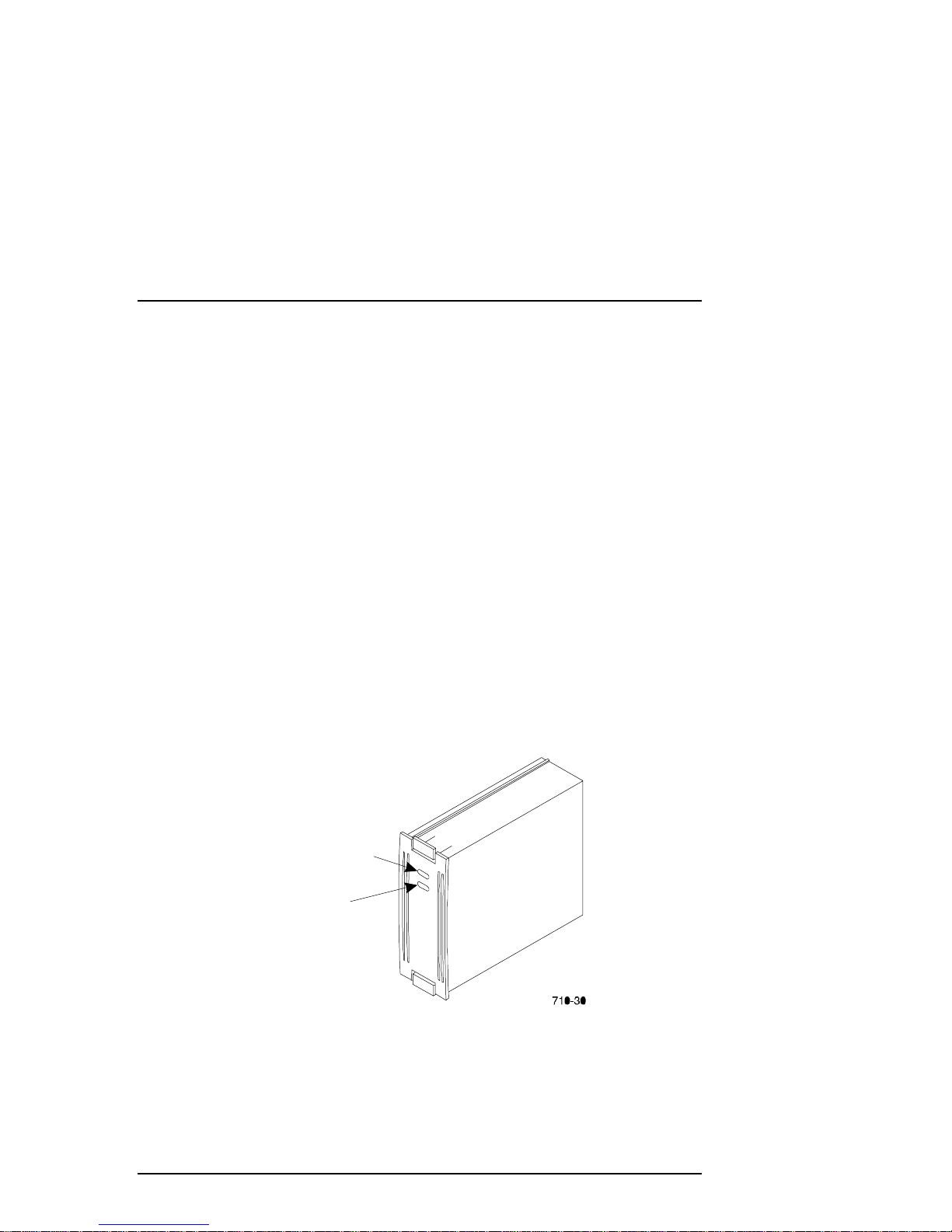
1.2.3 Single-Ended I/O Module (SE I/O)
Figure 1–7 Single-Ended I/O Module Location
EK–SMCPP–UG. A01 1–7

RA7000 and ESA10000 Storage Subsystems
Each SCSI enclosure, whether it is a master or an expansion enclosure, has six
I/O modules mounted at the bottom rear of the enclosure as shown in Figure 1-7.
In all enclosures these modules are the interconnection point between the
controller in the master enclosure and the devices in the expansion enclosures. In
an UltraSCSI RAID subsystem, the I/O modules, the internal SCSI buses, and the
controller ports all have the same number. For example, controller port 2, SCSI
bus 2, and I/O module 2 are different elements of the same bus. The major
features of the single-ended I/O module are described in the following sections.
1.2.3.1 Expanding the UltraSCSI Bus
Each I/O module has an UltraSCSI single-ended bus expansion integrated circuit.
This device isolates the internal and external SCSI bus and extends the length of
the SCSI bus.
Figure 1–8 Single-Ended I/O Module
External
TERM POWER
disable LED
The two VHDCI female connectors are the connection points for expanding the
SCSI buses between enclosures (see Figure 1-8). These connectors are wired in
parallel and act as a tri-link connector. In an expansion configuration, DIGITAL
recommends that maximum cable length not exceed 1.5 m (4.6 ft.) between
enclosures. DIGITAL supplies a cable kit, DS-BNK37-IE, containing the
necessary cables to connect an expansion unit.
1–8 EK–SMCPP–UG. A01
Internal
TERM POWER
disable LED
CXO5947A

Chapter 1. Product Description
1.2.3.2 Controlling the Internal SCSI Bus
The I/O module controls the internal SCSI bus in the following manner:
Isolates the internal SCSI bus from the external SCSI bus.
•
Provides single-ended SCSI bus termination.
•
Disconnects the internal SCSI bus from the external SCSI bus when the
•
EMU so directs.
Distributes TERMPOWER (+5 V dc) to the internal SCSI bus.
•
Turns ON the green internal TERMPOWER LED (see Figure 1-8) when the
•
internal TERMPOWER is present.
Turns OFF the green internal TERMPOWER LED (see Figure 1-8) when
•
there is an internal TERMPOWER overcurrent condition.
1.2.3.3 Controlling the External SCSI Bus
The I/O module controls the external SCSI bus in the following manner:
Provides single-ended SCSI bus termination.
•
Distributes TERMPOWER (+5 V dc) to the external SCSI bus.
•
Turns ON the green external TERMPOWER LED (see Figure 1-8) when the
•
external TERMPOWER is present.
Turns OFF the green external TERMPOWER LED(see Figure 1-8) when
•
there is an external TERMPOWER overcurrent condition.
Automatically disables the external bus termination when a cable is
•
connected to the right hand VHDCI connector.
1.2.3.4 Controlling the Fault Bus
The I/O module controls the fault bus operation in the following manner:
Provides a fault bus driver for improved signal transmission.
•
Distributes the FAULT_CLK and FAULT_DATA signals from the master
•
enclosure to the expansion enclosures.
Distributes the SHELF_OK and SWAP_L signals from the expansion
•
enclosures to the master enclosure.
1.2.3.5 “Warm Swapping” I/O Modules and Cables
You can replace either the I/O module or a cable when the associated SCSI bus is
quiesced (no data transfers occurring) – a warm swap. This enables you to
correct problems affecting only one bus without disrupting data transfers on the
other five buses.
EK–SMCPP–UG. A01 1–9

RA7000 and ESA10000 Storage Subsystems
The maximum bus length, including external cables (distance from the I/O
module terminator to the last terminator on the bus) is a function of the bus speed
and the number of devices. If the external bus is configured point to point (from
SE I/O module-to-SE I/O module with no devices installed in between), the
cables may be extended to 20 meters due to the isolation and re-timing circuitry
of the SE I/O module.
1.3 Error Detection and Reporting
The subsystem error detection and reporting function has two major elements –
the fault bus and the EMU (environmental monitor unit). For a detailed
discussion of error detection, fault reporting, and correction, refer to Chapter 4,
Error Analysis and Fault Isolation.
1.3.1 Fault Bus
The subsystem fault bus monitors subsystem operation and reports fault
conditions to the HSZ70 RAID array controller and the EMU. The controller and
EMU then report the error condition to the user. The fault bus monitors the
following conditions:
Blower failure (SHELF_OK)
•
Power supply failure (SHELF_OK)
•
Storage device removal (SWAP_L)
•
Storage device installation (SWAP_L)
•
SBB failure (FAULT_CLK, FAULT_DATA)
•
The fault bus consists of three subsystem backplane signals routed to the
controller port connectors as follows:
•
Shelf Status Signal
subsystem power (ac and dc) and blower operation
•
SBB Swap Signal
removed from or inserted in the subsystem
•
SBB Fault Signals
address or indicates a device fault. This device fault LED is controlled by
the fault clock (FAULT_CLK) and the fault data (FAULT_DATA) control
signals.
– The SHELF_OK status signal indicates the state of
– The SWAP_L signal is asserted whenever an SBB is
– The SBB amber LED displays either the storage
1–10 EK–SMCPP–UG. A01

Chapter 1. Product Description
1.3.2 Environmental Monitor Unit (EMU)
The primary function of the EMU (see Figure 1-9) is to monitor, process, report,
and display enclosure and controller environmental status information for the
power supplies, temperature, blowers, configuration, SCSI addressing, I/O
modules, communications, and the EMU microcode type. The EMU and
controller can exchange and process this information.
CAUTION
Proper operation of an UltraSCSI subsystem
requires an operational EMU and PVA in each
BA370 rack m ountable enclosur e. You mus t also
establish communications links between the
EMUs to ensur e proper subsystem operation and
error reporting.
The primary EMU function is monitoring and reporting UltraSCSI enclosure
environmental status. In conjunction with the PVA and the controller, the EMU
identifies controller faults and alerts the user of existing or impending failures
using one or more of the following error reporting systems:
EMU LEDs
•
The EMU audible alarm
•
Error messages on the host interface
•
Enclosure system OK LED
•
Enclosure system fault LED
•
In some instances, such as blower failures or high ambient or internal enclosure
temperatures, the EMU automatically initiates corrective actions (for example,
operating the blowers at high speed).
When there is the possibility of component damage due to overheating, the EMU
can initiate an automatic controlled power shut down.
1.3.2.1 Controller Status
The master EMU also monitors the state of both controllers. Should the EMU
detect a controller fault it can:
Sound the audible alarm
•
Cause the EMU system fault status LED to flash
•
Display a controller fault code on the blower LEDs when you momentarily
•
press the Alarm Control switch
EK–SMCPP–UG. A01 1–11

RA7000 and ESA10000 Storage Subsystems
When an error is detected on the EMU controller communications path, it causes
a controller fault.
1.3.2.2 I/O Module Status
The EMU also ensures that all six I/O modules are present, are properly installed,
and that each has TERMPOWER. If any of these conditions are not met, the
EMU reports an error condition. The EMU also reports each I/O module type to
the controller. Should the controller determine that the I/O module configuration
is incorrect, it displays this information on the console.
An integrated circuit on each I/O module functions as an UltraSCSI bus
extender. The EMU and the controller can enable or disable individual I/O
module circuits, thereby controlling individual external SCSI buses.
1.3.2.3 Enclosure Configuration Information
The EMU maintains the following configuration information:
Enclosure number
•
EMU microcode version
•
EMU message protocol version
•
PVA SCSI ID setting
•
Temperature sensor set points
•
The number of installed power supplies by location
•
The number of installed SBBs by location
•
The number of installed blowers by location
•
1–12 EK–SMCPP–UG. A01

Chapter 1. Product Description
1.3.2.4 EMU Front Panel
The EMU front panel contains all of the user interface controls, connectors, and
displays (see Figure 1-9 and Table 1-2).
Figure 1–9
Environmental Monitor Unit (EMU)
EMU
COMMUNICATIONS
CONNECTOR
SYSTEM FAULT LED
AND ALARM CONTROL
SWITCH
EMU
MAINTENANCE
CONNECTOR
TEMPERATURE
FAULT LED
EMU
COMMUNICATIONS
CONNECTOR
POWER
STATUS LED
BLOWER
FAULT LED(S)
EK–SMCPP–UG. A01 1–13

RA7000 and ESA10000 Storage Subsystems
Table 1–2 EMU Front Panel Component Descriptions
Component Function
EMU Com. Connector
(LEFT )
System Fault LED
(amber) and Alarm
Control Switch
Provides inter-EMU communications to another
EMU.
The System Fault LED in the Alarm Control Switch is
ON whenever there is an error condition.
This LED is FLASHING whenever the EMU has one
or more fault codes to display.
When there is a fault code, momentarily pressing this
switch turns OFF the audible alarm and starts the
fault code LED display.
Pressing the Alarm Control switch for at least 5
seconds clears all the active fault codes.
After a controlled power shut down, momentarily
pressing this switch will restore power to the
enclosure.
Temperature Fault LED
(amber)
Whenever either the ambient temperature or the
enclosure backplane temperature exceeds the user-
defined temperature set point, this LED is ON until
the condition is corrected.
Power Status LED
(green)
This LED is ON whenever there are:
At least four operational +5 V dc power supplies
At least four operational +12 V dc power supplies
TERMPOWER is present on all six I/O modules
This LED is OFF whenever there are:
Fewer than four operational +5 V dc power supplies
Fewer than four operational +12 V dc power supplies
One or more I/O modules are missing
TERMPOWER
EMU Maintenance
Connector
You can connect a maintenance terminal or PC to
this connector to display EMU:
Error messages
Information messages
A PC can also load EMU microcode through this
connector.
Blower Fault LEDs
(amber)
One or more of these eight blower fault LEDs are
ON whenever one or more blowers are:
Not operating
Not operating at the correct speed.
Removed
There is a fault code display
EMU Com. Connector
(RIGHT)
Provides inter-EMU communications to another
EMU.
1–14 EK–SMCPP–UG. A01

Chapter 1. Product Description
1.3.3 Power Verification and Addressing (PVA) Module
Proper operation of the subsystem, whether it be a master or an expansion
enclosure, requires both a PVA module and an EMU module. The PVA (Figure
1-10) and its associated EMU ensures that all major UltraSCSI components are
functioning properly. When an error condition occurs, these modules notify the
user that a problem exists. The controller identifies the specific problem. The
PVA and EMU LED displays identify possible causes of the problem.
The PVA mounts in the lower right section of the enclosure, directly above the
controller. The PVA and EMU have the same physical dimensions, use the same
type connectors, and are mounted next to each other – the EMU on the left and
the PVA on the right (see Figure 1-6). They are not interchangeable.
Figure 1–10 Power Verification and Addressing (PVA) Module
As shown in Figure 1-10, the major user-accessible components of the PVA
include the following:
The dc power shutoff switch includes a green power status LED
•
The UPS connector (RJ-45) for future expansion
•
The enclosure SCSI address switch that establishes the enclosure address
•
and thereby the SCSI bus Ids for each storage device
EK–SMCPP–UG. A01 1–15

RA7000 and ESA10000 Storage Subsystems
The PVA has two status indicators:
The green power status LED in the power Shut down switch. This LED is
•
ON whenever there at least four operational power supplies. When an error
condition occurs, the LED is OFF and the PVA reports the error to the
EMU. The EMU also monitors the power supplies for this condition
An audible alarm that beeps at a slow rate when the PVA detects removal of
•
or improper installation of the EMU. This ensures you are aware the EMU
must be replaced within 8 minutes to prevent a system shut down
The primary functions of the PVA include the following:
1) Ensures that there is a minimum of four operational power supplies in the
enclosure. If the PVA senses less than four power supplies, it notifies the
EMU.
2) Allows the user to select the DIGITAL-supported device SCSI bus
addresses for the master and each expansion enclosure.
3) Monitors the EMU status and:
Notifies the user of removal of the EMU
•
Notifies the user when there is no master EMU
•
Notifies the user when there are multiple master EMUs
•
Provides the user a switch to disconnect dc power from the enclosure
•
power buses
Monitors the optional UPS for proper operation and reporting the UPS
•
status
1.3.3.1 Monitoring Power Supply Operation
For accurate, reliable transfer of data without data corruption or loss, the
enclosure requires a minimum of four operational power supplies to furnish both
+5 and +12 Vdc for operation of the following:
Storage Devices (SBBs)
•
Controllers and cache memories
•
EMU
•
PVA
•
1–16 EK–SMCPP–UG. A01

Chapter 1. Product Description
Therefore, both the EMU and PVA monitor all of the power supplies (a
maximum of eight) to ensure that at least four are operational. An error condition
is indicated by one of the following conditions:
The +5 Vdc voltage drops to +4.7 Vdc
•
The +12 Vdc voltage drops to 11.4 Vdc
•
Another voltage essential for proper operation is the +5 Vdc termination power
(TERMPOWER) required for the SCSI bus on each of the six I/O modules. If
this voltage drops to +4.5 Vdc, an error condition exists.
As long as there are four operational supplies and TERMPOWER is correct, the
EMU and PVA generate the POK (power OK) signal. As long as POK is present
the controller can continue to transfer data providing there are no other error
conditions.
The loss of the POK signal for any reason causes the controller to reset and halt
all data transfers. All six buses remain quiesced (no data transfers occurring)
until the controller determines that power is correct. The controller does this by
checking the status of the POK signal. Until the POK reports that there are at
least four operational power supplies and that TERMPOWER is correct, the
controller, the cache memories, and all the devices remain passive. The EMU
and the PVA continue to monitor the system and report the error condition.
1.3.3.2 Master Enclosure Controlled Power Shutdown
The EMU can shut down the dc power in the master enclosure or the subsystem
when one of the following conditions occur:
The EMU determines an extreme over-temperature condition that requires
•
removing power from the subsystem
The user presses and holds down the PVA dc power switch until the EMU
•
initiates a controlled power shut down
NOTE
This is only true if both controllers have been
shut_down
When you initiate a controlled power shut down from the master enclosure PVA
the sequence of events is as follows:
1) The EMU changes its status to indicate that the dc power switch was pressed
2) The master EMU notifies the controller of the change in status.
3) When the controller is ready, it sends a controlled power shutdown
command to the master EMU.
4) A controlled power shut down is completed on all the subsystem cabinets.
EK–SMCPP–UG. A01 1–17

RA7000 and ESA10000 Storage Subsystems
NOTE
If the master EM U is not communi cating with t he
controller or the controller does not support a
control led s hut down, t he m ast er EM U c ommands
all enclosures to perform an immediate power
shut down.
1.3.3.3 Expansion Enclosure Initiated Power Shutdown
NOTE
This procedure will only work when the
controller(s) have been shut_down.
When you press the PVA dc power switch on the enclosure and the expansion
EMU
communicate with the master EMU, one of the following power
can
shutdown operations occurs:
NOTE
When the expansion EMU
with the master EMU, pressing the dc power
switch causes an immediate controlled power
shutdown of only the expansion enclosure.
cannot
communicate
1. The slave EMU changes its status to indicate that the dc power switch was
pressed.
2. The master EMU notes the change in status.
3. The master EMU notifies the controller of the change in status.
4. When the controller is ready, it sends a controlled power shut down
command to the master EMU.
5. A controlled power shut down is completed on all the subsystem cabinets.
NOTE
If the master EM U is not communi cating with t he
controller or the controller does not support a
control led s hut down, t he m ast er EM U c ommands
all enclosures to perform an immediate power
shut down.
1–18 EK–SMCPP–UG. A01
Chapter 1. Product Description
1.3.3.4 PVA UPS (Uninterruptable Power Supply) Options
DIGITAL does not supply any options for this product. When you install an
optional UPS power source, you can use the PVA to monitor its status. Connect
the UPS to the UPS Connector on the front of the PVA using a 9-pin RS-232-to8-pin RJ-45 adapter cable. The PVA monitors the following UPS signals and
reports the status to the EMU:
UPS installed
•
UPS has only two minutes of battery power left
•
UPS has lost ac input
•
1.4 Storage Device SBBs
The subsystem can accommodate up to twenty four 3½-inch storage device SBBs
(Figure 1-11). Each occupies one slot (six SBBs per shelf). The SCSI device
addresses of the SBBs can be assigned in the following ways:
By the backplane connector
•
With the SCSI device address switch mounted on the rear of the SBB
•
The HSZ70 RAID array controller software product descriptions and release
notes list the subsystem compatible SBBs.
Figure 1–11 Disk Drive SBB
DEVICE
ACTIVITY
(GREEN)
DEVICE
FAULT
(AMBER)
EK–SMCPP–UG. A01 1–19
RA7000 and ESA10000 Storage Subsystems
1.5
Power Configuration
There are two primary storage subsystem power configurations:
•
Standard
five power supply SBBs on power bus
•
Redundant
– 4 + 1 power configuration includes one ac power controller and
A
– 4 + 4 power configuration includes one ac power controller
and four power supply SBBs on power bus A and four power supply SBBs
on power bus
B
When there are less than four operational power supplies, the subsystem will
cease operating to preserve and protect the data. Table 1-2 lists the storage
subsystem power components and configurations.
CAUTION
A minimum of four operational SBB power
supplies are required for operation of the
subsystem. The fifth SBB power supply prov ides
redundancy.
Table 1–2 Storage Subsystem Major Power Components
Component Order No. Power Configurations
Standard Redundant
ac Power Entry
Controller
Shelf Power Supply
SBB
DS-BA35X-HE 1 2
DS-BA35X-HH 5 8
1.5.1 AC Power Entry Controllers
The ac input power is routed from the wall outlet to one of the power entry
controllers (Figure 1-12) that may have either of the following input voltages:
100 – 120 V ac, 60 Hz, single-phase, 12A
•
220 – 240 V ac, 50 Hz, single-phase, 6A
•
Each power entry controller has a system ON/OFF switch and distributes ac
power to all power supply SBBs on either power bus A or power bus B.
1–20 EK–SMCPP–UG. A01

Figure 1–12 AC Power Entry Controller
Chapter 1. Product Description
EK–SMCPP–UG. A01 1–21

RA7000 and ESA10000 Storage Subsystems
1.6 Power Supply SBBs
CAUTION
The subsystem requires power s uppl y SBBs r ated
for at least 180 W such as the DS-BA35X-HH.
You cannot use l ower rat ed s upplies , s uch as the
131 W (DS-BA35X-HA), the 145 W (DS-BA35XHD), or the 150 W (DS-BA35X-HF).
The 180 W shelf power supply SBB (Figure 1-13) converts the ac voltage from
the power controller to +5 V dc and +12 V dc for distribution throughout the
storage subsystem. The maximum capacity of the storage subsystem is eight
power supplies.
Figure 1–13 Typical Shelf Power Supply SBB
POWER
STATUS LED
(GREEN)
POWER SUPPLY
STATUS LED
(GREEN)
The 4 + 1 standard configuration provides five power supplies connected to
power bus A (the black power cords). As long as any four of these supplies are
operational, the subsystem is operational. The failure of a second supply places
the subsystem controller in a reset state. This precludes further data processing
and prevents the corruption or loss of the stored data.
With the 4 + 4 full redundant power option, the subsystem can survive multiple
power supply faults. To fully realize the benefits of the 4 + 4 configuration,
connect the power controllers to different ac distribution circuits on the same site
distribution panel.
1–22 EK–SMCPP–UG. A01

Chapter 1. Product Description
The four subsystem power supply SBBs on the left end of the shelf are connected
to power controller A. The four on the right end of the shelf are connected to
power controller B.
1.7 Standard (4 + 1) Power Configuration
NOTE
The black power c ord at the upper right c orner of
the subsystem is used only for the standard (4 +
1) configur ati on. It is not us ed for the r edundant (4
+ 4) configuration.
This standard power configuration (Figure 1-14) is the minimum configuration
DIGITAL recommends. If a power supply SBB fails you might be able to replace
it before a second fails. The standard power configuration has the following
components:
5 – power supply SBBs
•
1 – power entry controller
•
Any one of the following errors will cause the subsystem to cease operation:
Failure of two power supply SBBs
•
Failure of the power entry controller
•
Failure of the ac power source
•
Failure of the PDU (ESA10000 only)
•
EK–SMCPP–UG. A01 1–23

RA7000 and ESA10000 Storage Subsystems
Figure 1–14 Standard Power Configuration (4 + 1)
1–24 EK–SMCPP–UG. A01

Chapter 1. Product Description
1.8 Redundant (4 + 4) Power Configuration
A full redundant power configuration requires two separate power sources, two
ac power controllers, and eight shelf power supplies (Figure 1-15). DIGITAL
recommends this configuration to provide complete power system redundancy
thereby ensuring complete data protection. Any one of the following error
conditions will cause the subsystem to cease operation:
Failure of five power supply SBBs
•
Failure of both power entry controllers
•
Failure of the ac power source
•
Failure of both PDUs (ESA10000 only)
•
The primary ac source provides power to controller A, which distributes the ac
power through the four black power cords to the four power supply SBBs on the
left end of each shelf.
The second, or redundant, ac source provides power to controller B. The four
power supply SBBs on the right end of each shelf are connected to power bus B
with the four gray power cords.
Figure 1–15 Redundant Power Configuration (4 + 4)
EK–SMCPP–UG. A01 1–25

RA7000 and ESA10000 Storage Subsystems
1.9 ECB SBBs
The external cache battery (ECB) SBB provides power to the RAID array
controller cache module if system power fails. The cache module in turn
provides power to the ECB during normal operation. Two ECBs mounted in each
SBB module provide support for two cache modules. Each has a power
connector, status LED, and battery disable switch (see Figure 1-15).
To check the ECB status, look at the ECB status LED (one for each cache
module) for the appropriate indication (see Figure 1-16 and Table 1-3).
Figure 1–16 External Cache Battery (ECB) SBB
1–26 EK–SMCPP–UG. A01

Table 1–3 ECB Status Indications
LED Status Battery Status
System power is on and the ECB is fully charged.
System power is on and the ECB is charging.
System power is off and the ECB is supplying power to the cache.
System power is off and the ECB is not supplying power to the cache.
LEGEND
Chapter 1. Product Description
=Off = On = Blink
fast
= Blink
slow
The ECB SBB is mounted at the top of the SW370 cabinet. A Y-cable connects
the ECB to the array controller cache module. The cache is mounted under the
controller and is identified by the single plug in the middle of the module (Figure
1-17). Cache module to ECB cables are factory installed.
CAUTION
The ECB cable is configured in a “Y” for
convenient r outi ng wit hin t he c abinet . The c abl e i s
only to be us ed to connect ONE batt ery to ON E
cache module. Do not connect both ends of the
ECB “Y” cable at the same time during normal
operation. See chapter 5 of this manual for ECB
replacement.
EK–SMCPP–UG. A01 1–27

RA7000 and ESA10000 Storage Subsystems
Figure 1–17 Cache-to ECB-Connection
1.10 Subsystem Cooling
As shown in Figure 1-18, the subsystem is equipped with eight dual-speed
blowers. These blowers pull air in from the front of the cabinet, through the
SBBs, controllers and EMUs, and exhaust it out the rear. Backplane connectors
provide +12 V dc to operate the blowers and route the blower status signals to
the shelf backplane and the EMU.
The EMU may be set to automatically increase fan speed or set to a constant
fanspeed of high. Refer to the
commands.
If set for automatic, the EMU switches all operational blowers from low-speed to
high-speed when one or more of the following conditions occur:
When a blower is removed
•
When a blower malfunctions
•
When a blower is not rotating at the right speed
•
When the EMU detects an over-temperature condition
•
When the fault condition is corrected, the EMU returns the blowers to low speed.
1–28 EK–SMCPP–UG. A01
CLI Reference Manual
for the
set_emu

Figure 1–18 Dual Speed Blower Locations
Chapter 1. Product Description
EK–SMCPP–UG. A01 1–29

RA7000 and ESA10000 Storage Subsystems
1.11 Setting the PVA SCSI Address
The SCSI bus address switch on the front of the PVA module (see Figure 1-19)
controls the SCSI address (device ID) of each storage device in the enclosure.
The following configuration rules (restrictions) apply in establishing the PVA
SCSI bus address:
1. The master PVA address is always 0.
2. There is only one master PVA in any subsystem installation.
3. In an expansion subsystem, no two enclosures can have the same address.
4. DIGITAL does not support any PVA address that assigns SCSI bus device
addresses 6 or 7 to any storage device.
5. DIGITAL does not support any combination of PVA addresses that assign the
same SCSI bus device address to more than one device on any SCSI bus.
Figure 1–19 PVA SCSI Address Switch
DECREASE
SWITCH
To decrease the configuration number:
Press the upper switch to step the address down one address at a time
(decrement) until the preferred configuration number is displayed.
To increase the configuration number:
Press the lower switch to step the address up one address at a time (increment)
until the preferred configuration number is displayed.
1–30 EK–SMCPP–UG. A01
INCREASE
SWITCH

Chapter 1. Product Description
1.11.1 DIGITAL Supported Master PVA Address
DIGITAL supports PVA address “0” only for the master enclosure. Figure 1-20
defines the SBB device IDs for a master enclosure, one expansion, and two
expansion units. The device addresses are denoted to the right of Figure 1-20.
Figure 1–20 Enclosure SCSI Bus Addresses for all SBB Device IDs
SCSI
Bus 2
SCSI
Bus 1
ID3
ID2
ID1
Typical Backplane Connection
ID0
SCSI
Bus 3
SCSI
Bus 4
SCSI
Bus 6
SCSI
Bus 5
Device
Address 3/11/15
Device
Address 2/10/14
Device
Address 1/9/13
Device
Address 0/8/12
ID7
ID6
Cache module Cache module
EK–SMCPP–UG. A01 1–31
EMU
PVA
PVA
Address 0/2/3
Device
Address 7
Device
Address 6
CXO5889A

RA7000 and ESA10000 Storage Subsystems
1.11.2 DIGITAL Supported Expansion PVA Addresses
DIGITAL only supports PVA addresses 2 and 3 for expansion enclosures. Figure
1-20 defines the SBB device IDs for these two settings of the PVA SCSI bus
address switch, respectively. The use of these addresses in combination depends
on the number of enclosures and possible addressing conflicts.
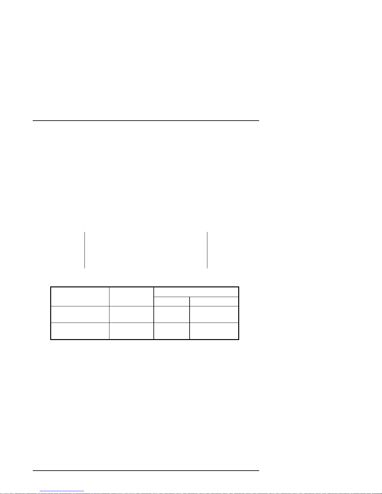
CAUTION
DIGITAL does not support any PVA address
combination not listed in Table 1-4.
Table 1–4 Expansion Enclosure Address Combinations
Enclosure PVA Address Switch
Setting for Two BA370
Rack Mountable units
Master
First
Expansion Unit
Second
Expansion Unit
00
22
N/A 3
PVA Address Switch
Setting for Three BA370
Rack Mountable units
1.11.3 Non-Supported PVA SCSI Bus Addresses
DIGITAL
Address 1
•
Address 4
•
Address 5
•
Address 7
•
does not
This PVA address assigns controller SCSI bus device addresses 6 and
7 to storage devices.
This PVA address assigns addresses already assigned to the master
enclosure.
This PVA address assigns controller SCSI bus device addresses 6 and
7 to storage devices.
This PVA address assigns addresses already assigned to the master
enclosure.
support the following PVA SCSI bus addresses:
1–32 EK–SMCPP–UG. A01

2
Unpacking and Installation
for the RA7000 and ESA10000
Storage Subsystems
This chapter describes the site preparation, unpacking, and installation procedures for
the RA7000 and ESA10000 Storage Subsystems.
2.1 Installing the RA7000
2.1.1 RA7000 Site Preparation
The RA7000 storage cabinet is designed for installation in a Federal
Communications Commission (FCC) Class A environment. Before installing the
storage cabinet, make sure that adequate space is available in front of the cabinet
for opening the front door (19 inches clearance) and around the cabinet for
adequate airflow. See Figure 2-1 for specific space requirements.
Figure 2–1 RA7000 Minimum Installation Clearance Measurements
482.60 mm
(19.00 in)
FRONT
DOOR
EK–SMCPP–UG. A01 2–1
DS-SWXRA-H
539.75 mm
x
(21.25 in)
482.60 mm
(19.00 in)

RA7000 and ESA10000 Storage Subsystems
2.1.2 Unpacking the RA7000 Subsystem Enclosure
The storage cabinet is packed in a corrugated carton attached to a wooden
shipping pallet, as shown in Figure 2-2A. Unpack the cabinet as follows:
NOTE
Before unpacking the equipment, inspect the
shipping carton for signs of external damage.
Report any dam age to the local carrier and to your
sales representative.
1. Remove the shipping straps (Figure 2-2A).
2. Remove the top cover (Figure 2-2B).
3. Remove the ramp from the top of the shipping carton (Figure 2-2B) and set
it aside for subsequent use in moving the cabinet off the pallet.
4. Remove the two foam cushions from the top of the cabinet container (Figure
2-2B).
5. Remove the cardboard carton surrounding the expansion cabinet
(Figure 2-2B).
6. Remove the plastic barrier bag (Figure 2-2C).
7. Once the cabinet is exposed (Figure 2-2D), examine the equipment for any
apparent damage. Report any problems immediately to your sales
representative.
2–2 EK–SMCPP–UG. A01

Chapter 2. Unpacking and Installation
Figure 2–2 Unpacking the RA7000 Storage Enclosure
2.1.3 Removing the RA7000 from the Pallet
Use the following procedure to remove the storage cabinet from the shipping
pallet:
Serious personnel injury may result if correct
safety precautions are not taken during the
removal procedure.
EK–SMCPP–UG. A01 2–3
WARNING

RA7000 and ESA10000 Storage Subsystems
1. Attach the ramp to the shipping pallet by fitting the lip of the ramp into the
groove on the pallet, as shown in Figure 2-3.
Figure 2–3 Installation of Ramp on Shipping Pallet
2. Lift the lock lever on each front caster to its up position so that the storage
cabinet can be moved.
WARNING
We recomm end that three people be as signed to
the task of unloadi ng the c abinet fr om it s shi pping
pallet. Failure to use sufficient personnel may
result in personnel injury and equipment damage.
CAUTION
Do not drop the storage cabinet from a height of
more than two inches as serious structural
damage can result.
2–4 EK–SMCPP–UG. A01

Chapter 2. Unpacking and Installation
3. Grasping the sheet metal base assembly, carefully lift the rear of the storage
cabinet over the “hump” in the center of the pallet and then roll the cabinet off
the pallet and down the ramp to the floor. If any further lifting of the cabinet is
required, grasp the sheet metal base assembly on the side and lift it carefully.
4. Retain the shipping container and all packing materials.
2.1.4 Placing the RA7000 Storage Enclosure
Use the following procedure to move the storage cabinet to its designated site:
WARNING
To prevent damage to the cabinet and injury to
personnel, make sur e to provide a cl ear path for
the casters.
1. Roll the expansion cabinet to the desired location.
2. If required, engage the lock on each front caster to prevent the cabinet from
moving.
2.1.5 Connecting the Enclosure to the Host
Refer to the
Getting Started Installation Guide
describing how to connect the RAID Array 7000 subsystem to the host.
for specific instructions
EK–SMCPP–UG. A01 2–5

RA7000 and ESA10000 Storage Subsystems
2.2 Installing the ESA10000
2.2.1 Site Preparation
Before installing the ESA10000, ensure that adequate space is available in front
of the enclosure for opening the front door and around the enclosure for adequate
airflow. See Figure 2-4 for specific space requirements.
Figure 2–4 Minimum Installation Clearance Measurements
600 mm
(23.6 in)
Rear door
Front door
SW600-series
cabinet
(Top view)
600 mm
(23.6 in)
900 mm
(35.4 in)
600 mm
(23.6 in)
2100 mm
(82.7 in)
CXO5825A
2–6 EK–SMCPP–UG. A01

Chapter 2. Unpacking and Installation
2.2.2 Unpacking the ESA10000 Subsystem
The ESA10000 comes wrapped in shrink wrap and attached to a wooden
shipping pallet. European shipments are also packaged with an outer corrugated
cardboard piece, which must be removed first. On the outside of both types of
packages, there resides an international de-skidding label, showing how to deskid the cabinet. Under the first layer of shrink wrap is the international
unpacking labels, showing how to unpack the ESA10000 and further instructions
on how to de-skid the ESA10000 cabinet. Unpack the unit as instructed by the
international unpacking label. See Figure 2-5.
NOTE
Before unpacking the equipment, inspect the
shipping carton for signs of external damage.
Report any dam age to the local carrier and to your
sales representative.
Figure 2–5 Shipping Container Contents
EK–SMCPP–UG. A01 2–7

RA7000 and ESA10000 Storage Subsystems
After using the international unpacking label information to unpack your
ESA10000, follow the de-skidding instructions on the international unpacking
label and the information on the international de-skidding label to push the
ESA10000 off the shipping pallet, keeping in mind the following warnings and
cautions.
WARNING
Serious personnel injury can result if correct
safety precautions are not taken during the
removal procedure.
We recomm end that three people perform the task
of unloading the ESA10000 SW600 cabinet from
its shipping pallet. Failure to use sufficient
personnel can result in personnel injury and
equipment damage.
The following procedure, along with the international unpacking label and Figure
2-5, will help you to remove the ESA10000 from the shipping pallet:
1. Remove the cover, the fasteners, and the corrugated board from the pallet.
2. Remove the cartons containing the ramp set and skirt kit and set them aside.
3. Cut the shipping straps. Some cabinets are packaged in a plastic or barrier
bag. If the cabinet arrives in a plastic bag, leave the bag in place until the
cabinet has adjusted to the local temperature and humidity.
4. Once the cabinet is unpacked, examine the front and rear doors, right and
left side panels, top panel, and undercarriage for any apparent damage.
Report such problems immediately.
5. Retain the shipping container and all packing materials.
2–8 EK–SMCPP–UG. A01

Chapter 2. Unpacking and Installation
2.2.3 Removing the ESA10000 from the Pallet
Use the following procedure to remove the cabinet from the shipping pallet:
1. Remove any packing material remaining on the pallet.
2. Remove the two unloading ramps from the carton and inspect them.
WARNING
Serious personal injury may resul t if correct safety
precautions are not observed during the
unpacking procedure. All personnel should wear
safety glasses. The ramps, ramp side rails, and
metal hardware should be inspected for the
following defects:
• Cracks more than 25 percent of the ramp
depth, either across or lengthwise on the
ramp.
• Knots or knotholes going through the
thickness of the ramp and greater than 50
percent of the ramp width.
• Loose, missing, or broken ramp side rails.
• Loose, missing, or bent metal hardware.
If any of thes e def ect s ex is t, do not us e the r amp.
Investigate alternate means of removing the
cabinet or order a new ramp. (The part number for
the ramp set is 99-08897-05.)
3. Attach the ramps by fitting the metal prongs into the holes on the pallet, as
shown in Figure 2-6. Make sure that the arrows on the ramps match up with
the arrows on the pallet.
EK–SMCPP–UG. A01 2–9

RA7000 and ESA10000 Storage Subsystems
Figure 2–6 Shipping Pallet Ramp Installation
4. Extend the ramps to their full length.
5. See Figure 2-7 for the location of the shipping bolts. Remove the bolts.
6. Remove the shipping brackets, shown in Figure 2-7, from the cabinet
levelers and set them aside.
2–10 EK–SMCPP–UG. A01

Figure 2–7 Shipping Bolts and Brackets
WARNING
Chapter 2. Unpacking and Installation
The levelers mus t be r ai sed f ull y for t he cabi net t o
roll easily down the unloading ramps. Failure to do
so may res ult in per s onnel i njur y as a res ult of the
cabinet tipping off the pallet or ramp
.
7. Loosen the leveler locking nuts and screw the four cabinet levelers all the
way up into the cabinet.
EK–SMCPP–UG. A01 2–11

RA7000 and ESA10000 Storage Subsystems
WARNING
Three people are required to unload the cabinet
from the shippi ng cabinet. Fai lure t o use s uffi cient
personnel may result in injury and equipment
damage.
8. Carefully roll the cabinet off the pallet and down the ramps to the floor as
shown in Figure 2-8.
Figure 2–8 Removing the Cabinet from the Pallet
2–12 EK–SMCPP–UG. A01

Chapter 2. Unpacking and Installation
2.2.4 Moving the ESA10000 to It’s Designated Site
WARNING
Using extreme caution when rolling the cabinet
across the floor. Failure to raise all leveler feet
and to provide a clear path for the cabinet's
caster s may res ult in t he c abinet tippi ng over and
injury to personnel.
Once the cabinet rack space is configured as desired, the cabinet may be rolled to
its final installation position. Secure loose cabinet cables up and out of the way
when rolling the cabinet.
2.2.5 Joining Adjacent ESA10000s
NOTE
Skip to Sec tion 2. 2.7 “Lev eling t he Cabinet” if y ou
do not have to join adjacent ESA10000 cabinets.
A cabinet joiner kit comes secured within the ESA10000 packaging. Use the
joiner kit to join two ESA10000 cabinets. In the joiner kit are instructions to
position the cabinets, to remove the side panels, to install the necessary joiner kit
hardware, to use the supplied Allen wrench, and how to complete the procedure
by installing trim pieces onto the cabinets. The following text will also help you
to start and complete the joining procedure, as you are referring to the
instructions contained in the joiner kit.
When joining two ESA10000’s, the recommended configuration is to have the
cabinet that resides on the left (viewed from the front) to have two BA370’s
installed with no controllers and for the cabinet that resides on the right to have
one BA370 in the bottom position with controllers installed in that BA370.
EK–SMCPP–UG. A01 2–13

RA7000 and ESA10000 Storage Subsystems
You must first remove one of the side panels from each cabinet before the joiner
kit can be installed. Refer to the joiner kit instructions and follow this procedure.
1. Open the back door of the cabinet to gain access to the screw attaching the
side panel to the cabinet.
2. Use a standard 5/16” nut driver or wrench to remove the single screw
holding the side panel to the rear vertical rail. The SW600 has only one
screw attaching the side panel to the cabinet. That screw is on the bottom,
rear vertical rail of the cabinet and is accessible from the inside of the
cabinet. You will install a shoulder bolt into that hole later as well as into the
corresponding hole in the front of the cabinet. Cabinet upper and lower
brackets on which the side panel rests hold the side panel in place.
3. From the outside of the cabinet, lift the side panel up and off. This may
require two people.
4. Store the side panel. Repeat Steps 1 through 4 for the other side panel.
5. Continue the joining process.
6. Position the two cabinets you are about to join next to each other, allowing
ample room to walk around both cabinets
7. As you face the front of the cabinets, position the cabinet containing
controllers to the right. Position the cabinet with no controllers to the left.
8. The correct side panels should already be removed.
9. From the outside of the left cabinet, screw a large head shoulder bolt into the
top hole below the rectangular cutout in the lower part of the cabinets
vertical rail (the hole from which you previously removed the screw that
held the side panel onto the cabinet). Screw a second large head shoulder
bolt into the front vertical rail hole that corresponds to the rear side panel
screw hole.
10. Using two screws provided, attach the top trim piece to the right cabinet.
11. Stand facing the side of the left cabinet (the side with the panel removed).
Install kep nuts over holes 9 and 12 from the top of the vertical cabinet rails,
front and rear. Install kep nuts over holes 9 and 12 from the bottom of the
vertical cabinet rails, front and rear.
2–14 EK–SMCPP–UG. A01

Chapter 2. Unpacking and Installation
12. Still facing the side with the panel removed, install a latch on the left front
top vertical cabinet rail through the kep nuts with the 10/32” screws
provided. Install a receiver on the right front top of the vertical cabinet rail
through the kep nuts with the 10/32” screws provided.. As you are standing
facing the side of the cabinet with the side panel removed, latches and
receivers should be oriented with the black colored part of the assemblies
facing outwards. Repeat this step at the bottom of the cabinet, again with the
latch to the left and the receiver to the right as you are facing the cabinet
side with the side panel removed. Note that the latch has the movable part
while the receiver does not.
13. Turn and face the side of the other cabinet with the sidepanel removed.
Repeat the procedure in Step 7 for the second cabinet.
14. Roll the two cabinets close together, aligning the joiner latches to the joiner
receivers.
15. Insert the large Allen wrench (provided) into one of the tool receptacle
holes on a bottom latch and turn clockwise to latch. Turn until the receiver
and latch “clicks” into place. Continue turning the Allen wrench until it can
not be turned further. Repeat for the other bottom joiner latch. Repeat for the
top joiner latches.
16. Slide the notch at the bottom of the front trim bracket over the large head
bolt that you attached to the lower front side of the left cabinet. Rotate the
upper part of the front trim bracket so that it slides in beneath the top trim
piece, which was installed in Step 5, and lock into place with a screw
through the top trim piece.
17. Slide the notch at the bottom of the rear trim bracket over the large head bolt
that you attached to the lower rear side of the left cabinet. Rotate the upper
part of the rear trim bracket so that it slides in beneath the top trim piece,
installed in Step 5, and lock into place with a screw through the top trim
piece.
EK–SMCPP–UG. A01 2–15

RA7000 and ESA10000 Storage Subsystems
2.2.6 Leveling the Cabinet
Level the cabinet in its final position as follows:
1. Loosen the locknuts on all four leveler feet as shown in Figure 2-9.
2. Turn each leveler hex nut clockwise until the leveler foot contacts the floor.
3. Adjust all four feet until the cabinet is level and the load is removed from all
casters. Verify that the casters spin freely.
4. Tighten the locknuts on all four leveler feet.
Figure 2–9 Leveler Foot Adjustment
2.3 Installing Additional Components
The following sections describe the procedures for installing additional
components into the ESA10000 data center cabinet.
2.3.1 Installing the BA370 Rack-Mountable Enclosure
You may wish to install an additional BA370 rack-mountable enclosure into your
ESA10000 to expand the storage capacity. The BA370 is shipped with a rack
mounting kit containing
mounting rails of the SW600 cabinet, and
to the sides of the BA370.
2–16 EK–SMCPP–UG. A01
mounting rails
, which you install onto the vertical
mounting brackets
, which you attach

Chapter 2. Unpacking and Installation
You must first install the BA370 mounting rails into the SW600 cabinet. Ensure
proper orientation of the rails by referring to Figure 2-10 while visually
inspecting the rails and reading the following text. It is very important that the
rails be installed into the SW600 cabinet properly oriented or the BA370 will not
install. The front of the rail has three protruding studs, with an alignment tab
approximately five inches behind the studs. The front of the mounting rail is
installed towards the front of the cabinet with the alignment tabs facing the
cabinet side panels and with the three protruding studs through designated holes
in the SW600 cabinet front vertical rails. The rear of the rail has a U-shaped
flange and two screw holes, one in the U-shaped flange and one in the rail itself.
The rear of the mounting rail is installed towards the rear of the cabinet. The
bottom of the rail has a flange running the entire length of the rail. The top of the
rail has a flange that runs most of the length of the rail from the rear of the rail to
approximately two inches from the front of the rail. Use Table 2-1 and Table 2-2
as a guide for installing the mounting rails into the proper holes of the vertical
mounting rails of the SW600 cabinet and refer to Figure 2-10 and 2-11.
EK–SMCPP–UG. A01 2–17

RA7000 and ESA10000 Storage Subsystems
Figure 2-10 Mounting Rail Orientation
Upper
stud
Middle
stud
Lower
stud
Alignment
tab
Table 2–1 Installing Rails for the Upper BA370
Rail Top Hole Bottom Hole
Upper BA370 , upper left rail 4 6
Upper BA370, lower left rail 26 28
Upper BA370, upper right rail 7 9
Upper BA370, lower right rail 24 26
If using Table 2-1, count the holes from the top of the SW600 cabinet.
Rear
mounting
hole
CXO5932A
Table 2–2 Installing Rails for the Lower BA370
Rail Top Hole Bottom Hole
Lower BA370 , upper left rail 28 26
Lower BA370 , lower left rail 6 4
Lower BA370, upper right rail 25 23
Lower BA370, lower right rail 8 6
If using Table 2-2, count the holes form the bottom of the cabinet.
2–18 EK–SMCPP–UG. A01

Chapter 2. Unpacking and Installation
1. Position the mounting rails in the hole positions indicated by Tables 2-1 or
2-2. The upper and lower studs on the front of the mounting rail align with
the indicated holes in the front of the SW600 cabinet. The alignment tab
slides into a hole on the inner front vertical rail of the SW600 cabinet that
corresponds to the middle stud of the mounting rail. Attach the front of the
mounting rail to the front of the cabinet using 2 5/16” nuts on the top and
bottom studs of each rail and tighten. Refer to Figure 2-11.
DO NOT
attach
a 5/16” nut to the middle stud of the mounting rail. This is reserved for
locking the BA370 into the cabinet.
2. Slide four U-Nuts onto the rear vertical rails of the SW600 cabinet and over
the obvious holes that correspond to the rear mounting holes of the SW600
cabinet’s vertical rails, as shown in Figure 2-11. Attach the rear of the
mounting rails to the SW600 cabinet by inserting a 10/32” X 5/8” screw
through the holes in the mounting rails, through the rear vertical rails of the
SW600 and through the U-nuts. Because the front of the mounting rail is
already attached to the SW600 cabinet, the rear hole on the mounting rail
should automatically align with the proper hole on the rear vertical rail of
the SW600 cabinet. If you have doubts on proper rear hole alignment, count
the number of holes on the front of the SW600 cabinet up to the middle stud
of the mounting rail. The rear screw attachment hole should correspond to
the middle stud hole on the front of the mounting rail as well as to the
alignment tab hole.
Figure 2–11 Rail Installation into Cabinet
Stud
Middle
stud
5/16"
nut
EK–SMCPP–UG. A01 2–19
U-nut
10/32"
screw
CXO5933A

RA7000 and ESA10000 Storage Subsystems
3. At this time, install the ECB into the right position (viewed from the rear) of
the ECB shelf, as shown in Figure 2-11. Install two ECB Y-cables , as
shown in Figure 2-12 and tie-wrap them to the SW600 cabinet’s inner
vertical rails. These cables will be connected to the ECB during a later step
in this procedure.
Figure 2–12 ECB Position
ECB
CXO5827A
Figure 2–13 Installing ECB Y-Cables
External cache
battery
2–20 EK–SMCPP–UG. A01
Cache
module
Unconnected
Unconnected
CXO5928A

Chapter 2. Unpacking and Installation
Now you must attach the
mounting brackets
to the BA370 rack mountable
enclosure.
1. Attach the mounting brackets to the sides of the BA370 using the two 8/32”
X 1/4” screws provided as shown in Figure 2-14. Notice that the mounting
bracket’s screw holes are one slot and one hole. Position the bracket so that
the slot is towards the front of the BA370. Install the screw into the screw
hole and tighten. Install the second screw into the screw slot and tighten.
Note that once attached, the bracket extends further towards the rear of the
BA370 than it does towards the front of the BA370.
Figure 2–14 Attaching Mounting Brackets to the BA370
Slot Hole
Now you are ready to install the BA370 rack-mountable enclosure into the
ESA10000 cabinet. Use the following procedure.
EK–SMCPP–UG. A01 2–21
2"
10"
CXO5934A

RA7000 and ESA10000 Storage Subsystems
WARNING
Installing the BA370 into an ESA10000 requires
two people. Never attempt to lift the BA370 by
yoursel f. Doing so may cause i njury, damage t he
equipment, or both. Nev er i ns tal l a BA370 int o the
upper posit ion of an ESA10000 unles s there is a
BA370 residing in the lower position already.
Doing so may cause injury, damage the
equipment, or both. Never attempt to install the
BA370 with SBBs ins t all ed. You mus t f ir s t r emove
all power supply and disk drive SBBs from the
BA370 before completing this installation.
Serious personnel injury can result if correct
safety precautions are not taken when installing
the BA370 rack-mountable enclosure
1. If power is applied to the cabinet, power down the HSZ70 controllers by
following the procedure contained in the
Array Controller HSOF Version 7.0 Service Manual
DIGITAL StorageWorks HSZ70
. Remove ac power to
the BA370 by moving the switch on the ac power controllers to 0. Remove
ac power to the Power Distribution Unit (PDU) by moving the breaker
switch to 0. Disconnect the power distribution unit from the ac power
source.
2. When you install an additional BA370 into the cabinet, you must also install
and tie-wrap the external cache battery (ECB) cable that connects the
HSZ70 controller to the ECB. Your ESA10000 comes precabled for ac
power. For the bottom BA370, tie-wrap each ECB cable to the bottom hole
on both front vertical siderails of the SW600 cabinet in the general vicinity
of the ac power cables that come pre-installed and tie-wrapped. For the top
BA370, tie wrap each ECB cable in the general vicinity of the ac power
cords tie-wrapped to the SW600 vertical rails Leave the ECB cable
extended in the front approximately 10 inches. This ensures that the ECB
cables can be plugged into the cache modules. Tie wrapping ensures that the
ECB cables are not damaged when you install a BA370.
3. Tuck the ECB cables and ac power cords behind the front vertical rail of the
BA370. Remember you left the ECB cables extended by 10 inches. Failure
to tuck the cables behind the cabinet rails may cause damage to the cables
when you install the BA370 into the cabinet.
2–22 EK–SMCPP–UG. A01

Chapter 2. Unpacking and Installation
4. Position the BA370 on the floor in front of the cabinet. Remove
supply and disk drive SBBs from the BA370
BEFORE
attempting to lift the
ALL
power
BA370.
5. With obe person on each side of the BA370, grasp the BA370 by the
mounting bracket with one hand and by the front top bank of the BA370,
with the other hand. Lift the BA370 up, matching the mounting brackets
with the mounting rails, and slide the BA370 into the SW600 cabinet
way
or
until the fans enter the cabinet
.
half
6. Plug the four-wire front door LED cable harness, which is tie-wrapped along
with the ac input power cables to the SW600 vertical rails, into the LED
cable harness on the top of the BA370.
7. Ensure all cables, LED, ECB and ac power, are out of the way and cannot be
damaged when the BA370 is slid entirely into the cabinet. Slide the BA370
into the cabinet until it stops.
8. Lock the BA370 into place by attaching a 5/16” nut over the middle stud on
the front of each mounting rail. In the rear of the cabinet, use a 10/32” screw
through the screw holes of the mounting rails and brackets. Refer to Figure
2-11. This effectively locks the BA370 securely into the SW600 cabinet.
9. Ensure the ac power distribution unit (PDU) circuit breaker is off and the ac
input power controller switch on the ac input power controllers is off.
10. Re-install all power supply and disk drive SBBs into the BA370.
11. For 4+1 power redundancy, plug black power supply cables into all left-hand
power supply SBBs and one black power cable into the right, top most
power supply SBB. Refer to Figure 1-14 in
Chapter 1
of this manual. For
4+4 dual power redundancy, plug all black power cords into all left-hand
power supply SBBs and plug all white power cords into all right-hand power
supply SBBs. Refer to Figure 1-15 in
Chapter 1
of this manual.
12. Ensure the HSZ70 controllers, EMU, and PVA are seated in the BA370 in
their proper locations. Also plug the ac power cord(s) into the ac input power
controller(s) on the front of the BA370.
EK–SMCPP–UG. A01 2–23

RA7000 and ESA10000 Storage Subsystems
13. For BA370’s with 4+4 power configurations, go to the rear of the cabinet
and plug the black ac power cord from the BA370’s ac power controller into
the bottom PDU that already has a black power cord plugged into it. For
dual-redundancy units, plug the gray ac power cord from the BA370’s ac
power controller into the top PDU in the rear of the SW600 cabinet. Attach
ECB cables to the ECB and to the cache modules The top BA370 ECB is
located on the left-hand side of the ECB shelf. The bottom BA370 ECB is
located on the right-hand side of the ECB shelf.
14. Plug the PDU ac power cable(s) into the ac power source.
2.4 Cabling a Master Enclosure to an Expansion Enclosure(s)
NOTE
One DS-BNK37-1E cable k it is requir ed for each
expansion unit.
2.4.1 Cabling Sequence
When adding an expansion BA370 unit, the following sequence is suggested.
1. Connect all six SE I/O cables between units..
2. After the SE I/O cables are attached, connect the EMU communication
cable.
3. The last step is to set the PVA address.
2.4.2 Attaching the SE I/O Cables
Figure 2–15 SE I/O Port Identification
642
531
There is a separate cable for each port of the controller and all cables are
identical. Refer to Figure 2-15 and attach the cables to one port at a time. SE I/O
cables are connected port-to port maintaining the same port number at each end.
Port 1 of the master unit connects to port 1 of the expansion unit(s), port 2 of the
master unit connects to port 2 of the expansion unit(s), and so forth. Start with
the bottom row (ports 1, 3, 5) first then the top row (ports 2, 4, and 6).
2–24 EK–SMCPP–UG. A01
CXO5819A

Chapter 2. Unpacking and Installation
Place the cable clip on each cable prior to attaching the cable to the I/O module.
Orient the connector on the cable to match the I/O module connector and plug
the cable connector into the I/O module connector.
Secure the cable by tightening the cable connector jackscrews.
NOTE
Do not omit the tightening of the jackscrews.
There is not enough c ontact pres sure to hold the
cables in place between enclosures.
Slide the cable clip along the cable and press it into the hole of the I/O module
bracket.
2.4.2.1 Cabling for One Expansion Unit
For a single expansion unit, cable from the
the master unit to the
terminated
side of the expansion unit. The terminated side
terminated
is identified by the resistor symbol, it is also the LEFT-hand connector of the SE
I/O module. See Figure 2-16.
Figure 2–16 SE I/O Port Wiring (One Expansion Unit)
642
side of the I/O module on
EK–SMCPP–UG. A01 2–25
531
Cable A
642
531
CXO5840A

RA7000 and ESA10000 Storage Subsystems
2.4.2.2 Cabling for Two Expansion Units
For two expansion units, cable from the
the master unit to the
unit. Then connect from the
expansion unit to the
terminated
unterminated
terminated
terminated
side of the I/O module on the first expansion
side of that I/O module on first
side of the I/O module on the second
expansion unit. The unterminated side is identified by the resistor symbol
enclosed in a circle with a diagonal bar across the symbol. It is also the RIGHThand connector of the SE I/O module. See Figure 2-17.
Figure 2–17 SE I/O Connections for Two Expansion Units
642
531
642
531
642
Cable A
Cable B
side of the I/O module on
531
2–26 EK–SMCPP–UG. A01
CXO5841A

Chapter 2. Unpacking and Installation
2.4.3 Attaching the EMU Communications Cable
Figure 2–18 EMU Front Panel
EMU
COMMUNICATIONS
CONNECTOR
SYSTEM FAULT LED
AND ALARM CONTROL
SWITCH
EMU
MAINTENANCE
CONNECTOR
EMU
COMMUNICATIONS
CONNECTOR
TEMPERATURE
FAULT LED
POWER
STATUS LED
BLOWER
FAULT LED(S)
Connect the EMU Communications cable from one EMU communications port
(See Figure 2-18) of the master RA7000 to the communications port of the first
expansion unit. If there is a second expansion unit, connect an EMU
communications cable from one EMU communications port of the first
expansion unit to a communications port of the second expansion unit. See
Figure 2-19.
Figure 2–19 Multiple EMUs Connected Together
CXO5820A
EK–SMCPP–UG. A01 2–27

RA7000 and ESA10000 Storage Subsystems
2.4.4 Setting the PVA Addresses
Figure 2–20 PVA Module Front Panel
DIGITAL supports enclosure addresses 2 and 3, only for expansion enclosures.
Figure 2-21 defines the SBB device IDs for these two settings of the PVA SCSI
bus address switch. The use of these addresses in combination depends on the
number of enclosures and possible addressing conflicts.
CAUTION
DIGITAL does not suppor t any enc losur e addres s
combination not listed in Table 2-3.
Table 2–3 Expansion Enclosure Address Combinations
Enclosure PVA Address Switch
Setting for Two BA370
Rack Mountable Units
Master
First
00
22
PVA Address Switch
Setting for Three BA370
Rack Mountable Units
Expansion
Enclosure
Second
N/A 3
Expansion
Enclosure
2–28 EK–SMCPP–UG. A01

Chapter 2. Unpacking and Installation
Figure 2–21 Expansion Enclosure SCSI Bus Addresses
SCSI
Bus 2
SCSI
Bus 1
ID3
ID2
ID1
Typical Backplane Connection
ID0
SCSI
Bus 3
SCSI
Bus 4
SCSI
Bus 6
SCSI
Bus 5
Device
Address 3/11/15
Device
Address 2/10/14
Device
Address 1/9/13
Device
Address 0/8/12
ID7
ID6
Cache module Cache module
EK–SMCPP–UG. A01 2–29
EMU
PVA
PVA
Address 0/2/3
Device
Address 7
Device
Address 6
CXO5889A

RA7000 and ESA10000 Storage Subsystems
2.5 Connecting SCSI Bus Cables to the ESA10000
The internal SCSI bus cabling of two BA370’s within an ESA10000 cabinet as
well as the SCSI bus cabling between a master and expansion cabinet is shown in
Figure 2-22. The cabling scheme is to route the upper BA370’s I/O module
number 1’s left port to the lower BA370’s I/O module number 1’s right port.
Route the upper BA370’s I/O module number 2’s left port to the lower BA370’s
I/O module number 2’s right port. Follow this cabling scheme for cabling SCSI
bus cables in an ESA10000 that contains two BA370’s.
To expand the SCSI bus from a master cabinet to an expansion cabinet, route the
lower BA370’s SCSI bus cables from I/O module number 1’s left port to the
expansion cabinet’s I/O module number 1’s left port. Notice for expansion that
the cables run from the left port of the master cabinet to the left port of the
expansion port, just the opposite as for SCSI bus cabling between two BA370’s
that reside in the same cabinet. Again refer to Figure 2-22 for help in routing
SCSI bus cables.
The maximum bus length, including external cables (distance from the I/O
module terminator to the last terminator on the bus) is a function of the bus speed
and the number of devices. If the external cable is figured from SE I/O module to
SE I/O module with no devices installed in the middle, the cables may be
extended to 20 meters due to the isolation and re-timing circuitry of the SE I/O
module.
2–30 EK–SMCPP–UG. A01

Chapter 2. Unpacking and Installation
Figure 2–22 SCSI Bus Cabling for the ESA10000
Expansion cabinet Master cabinet
642
531
642
531
EK–SMCPP–UG. A01 2–31
64 2
53
1
CXO5931A

RA7000 and ESA10000 Storage Subsystems
2.6 Installing SBBs
This section describes the procedures for installing Storage Building Blocks
(SBBs) into a BA370 rack mountable enclosure. The SBBs consist of disk drives,
power supplies, and the external cache battery.
2.6.1 Installing SBB Disk Drives
Initial and additional disk SBBs may be installed into the BA370 rack-mountable
enclosure. The recommended procedure for installing disk SBBs is to install
them into the enclosure bottom to top and from left to right as viewed from the
front of the enclosure.
Use the following guidelines when installing Disk SBBs into the BA370(s):
1. Install the 9GB Disk SBBs into each BA370
2. Fill the BA370 from bottom shelf to top shelf
3. Fill each shelf in a left to right order
4. Repeat this process for the 4GB Disk SBBs
5. Repeat this process for the 2GB Disk SBBs
Before beginning the Disk SBB installation process, group the Disk SBBs
according to capacity. If there is more than one BA370 enclosure involved,
divide each of the groups by total number of BA370 rack mountable enclosures.
Now distribute the disks (by capacity) amongst the BA370s. The goal is to
spread the disks across the BA370s to ensure that a raidset is not all on one
BA370. It is not necessary to favor the master BA370 [the one with the HSZ70
controller(s)] over the expansion enclosure(s).
Example:
DISK TYPE TOTAL NUMBER
OF DISKS BY
TYPE
RZ1DB, 9GB, WIDE Ultra
RZ1CB, 4GB, WIDE Ultra
RZ1BB, 2GB, WIDE Ultra
To install an SBB disk drive, hold it in both hands, insert the disk drive into the
designated guide slots and firmly push the disk drive into the shelf until the
mounting tabs snap into place.
2–32 EK–SMCPP–UG. A01
NUMBER OF
DISKS IN
MASTER
945
532
312
NUMBER OF
DISKS IN
EXPANSION

Chapter 2. Unpacking and Installation
Additional rules for configuring SCSI buses include:
1. All devices and ports in the same column are on the same SCSI bus or port.
2. All devices in the same row (device shelf) have the same device address.
3. Devices installed must be listed in the HSOF Ultra 70 Solutions Software
SPD.
4. Device address 4 and 5 are used only when the disk drive SBB has a device
address switch.
5. Device addresses are determined by the backplane connector into which the
device is inserted unless the SBB has a device address switch.
6. For the addressing of SBB disk drives on the SCSI bus, device addresses for
each SBB in each extender cabinet are determined by the PVA address. The
main cabinet’s PVA address is set to PVA address 0 and device addresses in
that cabinet have addresses 0 through 3. The PVA address in the first
extender cabinet is set to PVA address 2 and device addresses in that
extender cabinet have addresses 8 through 11. The PVA in the second
extender cabinet is set to PVA address 3 and device addresses for that
extender are from 12 through 15. Figure 2-21 helps to illustrate the
addressing scheme.
Figure 2-21 shows the six Ultra Wide SCSI buses and their associated ports and
device addresses.
EK–SMCPP–UG. A01 2–33

RA7000 and ESA10000 Storage Subsystems
2.6.2 Installing SBB Power Supplies
Each SBB power supply has two green status LEDs. The upper LED indicates
AC power status and the lower LED indicates power supply status. The
procedure for installing power supplies is basically the same for installing any
SBB. Refer to Figure 2-23 during the installation.
Figure 2-23 Installing Power Supply SBB (4+1 Shown)
SBB power
supply
AC power
controller
1. Insert the SBB power supply into the guide slots and push in until the power
supply is fully seated and the mounting tabs are engaged into the shelf.
2. Connect the power cord to the SBB power supply.
3. Turn on the AC input power controller.
4. Observe the power supply SBB LEDs. Both LEDs should be lit, indicating
proper power supply operation on the associated bus.
5. If the upper LED is not lit after installation this indicates that the power
supply is not functioning properly and needs to be replaced. If both status
LEDs are not lit after the installation, either there is a lack of AC power, the
AC input power controller has failed, or the SBB power supply just installed
has failed.
2–34 EK–SMCPP–UG. A01
CXO5930A

Chapter 2. Unpacking and Installation
2.6.3 Installing the AC Input Power Controller
There are no external indications of a power controller failure on the ac power
controller itself. Both status LEDs on the power supply being off indicate a
possible power controller failure. Use the following procedure to install a new
AC power controller. Refer to Figure 2-23.
1. Press 0 on the AC input power controller ON/OFF switch.
2. Insert the AC input power controller into the ESA10000 enclosure .
3. Tighten the two retaining screws at the top and bottom of the power
controller.
4. Connect the AC power cord to the power controller.
5. Press I on the AC power controller ON/OFF switch.
6. Observe the power supply status LEDs for proper operation.
EK–SMCPP–UG. A01 2–35

RA7000 and ESA10000 Storage Subsystems
2.6.4 Installing the External Cache Battery (ECB)
Install the external cache batteries (ECBs) into the ESA10000 into the ECB
shelf mounted in the rear of the cabinet. Refer to Figure 2-24.
Figure 2–24 Installing the External Cache Batteries
ECB
The following procedure details external cache battery installation
1. Insert the external cache battery into the guide slots of the rear mounted
shelf.
2. Push in the external cache battery until it seats firmly into the shelf and the
mounting tabs engage the shelf.
3. Connect the ECB cable between the cache module and the ECB.
2–36 EK–SMCPP–UG. A01
CXO5827A

3
Configuring the Storage Cabinet
This chapter describes configuration rules and restrictions for configuring the
Environmental Monitor Unit. When specific rules and restrictions are not provided,
references are given to the proper StorageWorks documentation.
3.1 Configuring the Storage Cabinet
Configuring the storage cabinet is primarily configuring the EMU. Configuring
the EMU requires connecting the EMU communications bus and then using the
CLI SET_EMU command to establish the following:
Enclosure backplane temperature sensor set points on all enclosures
•
– SENSOR_1 or SENSOR_1_SETPOINT = DEFAULT
– SENSOR_2 or SENSOR_2_SETPOINT = DEFAULT
EMU module internal temperature sensor set point SENSOR_3 or
•
SENSOR_3_SETPOINT = DEFAULT
The blower speed controls of either FANSPEED = HIGH or FANSPEED =
•
AUTOMATIC
DIGITAL recommends setting the FANSPEED to AUTOMATIC, unless (1) the
ambient temperature is in excess of 38ºC (100ºF), (2) there is no air conditioning,
or both conditions exists. Should these conditions exist, DIGITAL recommends
setting the FAN SPEED to HIGH.
For inst ructions on us ing these commands , refer
CLI Reference Manual
to the
EK–SMCPP–UG. A01 3–1
NOTE
.

RA7000 and ESA10000 Storage Subsystems
3.1.1 Connecting the EMU Communications Bus
In an expansion configuration you must establish communications between the
master EMU and each of the expansion EMUs. This is accomplished by
connecting a communications port on each EMU to a communications port on
another EMU. By establishing an EMU communications bus chain you ensure
that the master EMU can monitor and control all the enclosures in the UltraSCSI
subsystem.
DIGITAL recommends that you use a BN25G cable no longer than 4 m (13.1 ft.)
to connect the EMUs.
3.1.2 Setting the Temperature Sensors
There three temperature sensors in each UltraSCSI enclosure – two on the rear of
the backplane in the top middle and one mounted on the EMU module. You have
the option of setting the temperature at which an individual sensor reports an
over-temperature condition. You enter the desired temperature in degrees Celsius
(°C) within the range of 0ºC (32°F) through 49°C (120°F). See Table 3–3 for the
relationship between °C and °F (Fahrenheit).
The EMU sensor monitors the input, or ambient, air temperature while the two
enclosure sensors monitor the exhaust air temperature. The exhaust air
temperature can be higher than the ambient air temperature.
For each of the three sensors you have the option of selecting
SENSOR_n_SETPOINT = DEFAULT which establishes a set point of 35°C
(95°F). DIGITAL recommends that you use this setting for all three sensors.
Should the ambient temperature regularly be higher than 35°C (95°F), DIGITAL
recommends you select a temperature setting that ensures the continued
operation without endangering the components. Setting the temperature sensors
to the highest expected ambient temperature should ensure optimum operation.
To ensure proper operation, enter all temperatures
in °C. You cannot enter t emperat ur es as f rac t ions ,
decimals, or in °F.
3–2 EK–SMCPP–UG. A01
CAUTION

Chapter 3. Configuring the Storage Cabinet
Table 3–1 EMU Set Point Temperatures
°C °F °C °F °C °F ºC °F °C °F
0 3210502068308640104
1 3411522170318841106
2 3612542272329042108
3 3713552373339143109
4 3914572475349344111
5 4115592577359545113
6 4316612679369746115
7 4517632781379947117
8 46186428823810048118
9 48196629843910249120
In an expansion configuration (two or more enclosures operating with the same
controller) you only set the master EMU temperatures. The temperature set
points for the other UltraSCSI enclosures, the “slaves”, automatically change to
match the setting for the master EMU.
3.1.3 Setting the Blower Speed Control
The UltraSCSI enclosure blowers normally operate at low speed and provide
sufficient air flow to cool the enclosure components and ensure proper operation.
You can use the CLI FANSPEED command to change the operating speed of the
blowers.
When you set FANSPEED = HIGH all blowers in all enclosures operate at
•
high speed
When you enter FANSPEED = AUTOMATIC the local EMU controls the
•
blower speed in each enclosure.
DIGITAL recommends using the FANSPEED = AUTOMATIC command to
enable the EMU in each enclosure to implement corrective action whenever any
one of the following error conditions occurs:
A blower fails
•
You remove a blower
•
A blower is rotating too slowly to provide sufficient air flow
•
The ambient air temperature (EMU intake) exceeds the user defined
•
temperature.
Either backplane (exhaust) temperature exceeds the user-defined
•
temperature
EK–SMCPP–UG. A01 3–3

RA7000 and ESA10000 Storage Subsystems
When the EMU detects any of these error conditions, it will automatically switch
all the operational blowers to high speed, thereby increasing the air flow through
the enclosure to reduce the possibility of component failure. Simultaneously, the
EMU can initiate the following actions:
Enable the audible alarm on the EMU
•
Turn on the amber System Fault LED whenever the temperature exceeds
•
one or more set points
Turn on the amber Temperature Fault LED
•
Notify the controller of the error condition
•
Start the EMU 8-minute timer when (1) all blowers in a bank are defective,
•
or (2) a blower is removed.
NOTE
Removing a blower significantly changes the air
flow pattern wi thin the enclos ure. This c an cause
an over-temperature condition in a very short
time. Ther efore, t his condi tion st arts the 8-m inute
timer.
When you momentarily depress the Alarm Control switch the EMU audible
alarm will turn off and the fault status LEDs remain on, At this time, the blower
LEDs will display the system fault codes (see EMU System Fault Code
Displays).
3.1.4 Alarm Control Switch
Whenever a power, environment, or blower error or fault condition occurs, the
EMU turns on the local audible alarm. At the same time, the alarm sounds and an
amber LED in the switch turns on. The alarm remains on until one of the
following conditions occurs:
Correction of the error condition
•
The user momentarily presses the Alarm Control switch
•
3–4 EK–SMCPP–UG. A01

Chapter 3. Configuring the Storage Cabinet
When you momentarily press the switch you turn off the audible alarm for all
current error conditions in the local subsystem. The alarm remains off until one
of the following conditions occurs:
One hour elapses
•
A different fault occurs
•
An existing fault clears and re-occurs
•
When you press and hold the switch for at least 5 seconds you clear all the fault
codes.
NOTE
The Alarm Control switch does not affect either
the error condition or the error code. Only
correcting the error condition will clear the error
code.
During a controlled power shut down, the Alarm Control switch functions as an
enclosure power switch. When a controlled power shut down isin affect, you
must press the Alarm Control switch to restore dc power to the enclosure.
EK–SMCPP–UG. A01 3–5


4
Error Analysis and Fault Isolation
This chapter describes the errors, faults, and significant events that can occur during t he
storage subsystem initialization and normal operation. The chapt er pr ovides a description
of the events and how to respond. The er r or and event descriptions isolate failures t o the
field replaceable unit (FRU). Refer to Chapter 5 for a list of FRUs.
4.1 Storage Subsystem Error Reporting
There are multiple light emitting diodes (LEDs) that display error conditions.
The two most easily observed are the subsystem front panel (Figure 4–1). You
must then use the EMU front panel ((Table 4–1), the power supply LEDs, the
storage SBB LEDs, and the controller LEDs to isolate the error condition to a
component.
The front panel LEDs are simple
System OK LED; the amber LED is the Fault LED. When the Fault LED is ON
you must check all the other status LEDs to determine the cause of the error.
go–no go
indicators. The green LED is the
EK–SMCPP–UG. A01 4–1

RA7000 and ESA10000 Storage Subsystems
Figure 4–1 Storage Subsystem Status LEDs
(RA7000 Shown)
The ESA10000 cabinet has Subsystem LEDs
mounted in the c abinet door and in a small panel
above each BA370 Rack Mountable Enclosure.
The cabinet door LEDs permit the operator to
determine the Subsystem status without opening
the cabinet door.
4–2 EK–SMCPP–UG. A01
NOTE

Chapter 4. Error Analysis and Fault Isolation
Table 4–1 Subsystem Status LEDs
When the LED display is. . . The subsystem status is . . .
Operating normally; there are no error
conditions.
There is a failed subsystem component.
Recommended Corrective Actions:
Check the EMU control panel LEDs to
determine which component has failed.
2. Check the host to determine and replace
the failed component.
The subsystem does not have power applied
or is in a RESET state.
Recommended Corrective Actions:
Check the EMU control panel LEDs to
determine which component has failed.
Check that there are at least four operational
SBB power supplies.
Check the system terminal for error
messages.
EK–SMCPP–UG. A01 4–3

RA7000 and ESA10000 Storage Subsystems
4.2 EMU Error and Fault Status Reporting
The EMU processes subsystem status reports, and when there is an error
condition, notifies the user of the problem using the EMU audible alarm and the
status LEDs (system, temperature, power, blower) located on the EMU front
panel (see Figure 4–2).
Whenever the audible alarm sounds, the user should check the EMU status LEDs
to determine the problem.
CAUTION
Should the audible alarm sound, but the status
LEDs not indicate an error condition, it possible
that the er ror c ondit ion no l onger ex i st s . Howev er ,
you should always check t he control ler err or log to
verify the error condition no longer exists.
The EMU reports the system status, to include error conditions, to the controller
which records this information in the error log and displays it on the controller
console.
Figure 4–2 EMU Front Panel Layout
4–4 EK–SMCPP–UG. A01

Chapter 4. Error Analysis and Fault Isolation
4.3 EMU Subsystem Status LEDs
Table 4–2 Shows the possible EMU status LED displays. LEDs that blink or
flash at a one second or greater interval are considered ON.
Table 4–2 EMU Subsystem Status LEDs
Symbol Condition
ON or blinking slowly (interval of 1 second or more).
OFF.
Flashing (blinking)
The EMU LEDs (see Table 4–3) display the status of the enclosure (System
Fault), the temperature status (overtemperature), error conditions (enclosure
fault), and the status of the individual blowers and banks of blowers. When the
enclosure is functioning properly, only the Power LED is ON. Table 4–3
describes:
The EMU LED display
•
The enclosure status associated with each display
•
The probable cause of the error condition
•
The actions recommended to correct the problem
•
Not all pos sibl e combinat ions of LED displ ays are
shown. For example, there ei ght dif ferent displ ays
for the failure of an individual blower. Therefore,
only a representative display of each error
condition type is shown.
EK–SMCPP–UG. A01 4–5
NOTE

RA7000 and ESA10000 Storage Subsystems
Table 4–3 EMU LED Displays
Display Subsystem Status
The subsystem is fully operational.
Comment
The dc power supplies and the blowers are operating
properly. The ambient and exhaust air temperatures
are within the user specified limits.
Over-temperature condition. Overheating can cause
system failure.
Probable Cause
The ambient temperature in one or more enclosure is
above the user-specified limit.
Temperature set point may be set too low for
environment.
Corrective Action
Complete first corrective action. If it does not correct
the problem, complete the second.
Determine and correct the cause of this condition as
quickly as possible to prevent the over-condition from
causing a subsystem reset or failure.
Change temperature set point.
Non-operational
Probable Cause
One of the following error conditions exists:
Either + 5 V dc or 12 V dc out of range.
TERMPOWER less than + 4.5 V dc on one or more
I/O modules.
Corrective Action
Complete first corrective action. If it does not correct
the problem, complete the second.
Observe the power supply status LEDs to determine
the defective power supply and replace it.
Examine I/O modules to find the one with either the
external or internal TERMPOWER LED ON and
replace it.
4–6 EK–SMCPP–UG. A01

Chapter 4. Error Analysis and Fault Isolation
Table 4–3 EMU LED Displays (continued)
Display Subsystem Status
Blower fault. Operational blowers are running at high
speed.
Corrective Action
Replace defective blowers.
Comment (Refer to Figure 1–18)
In this example, blowers 1 and 7 are not operating
and must be replaced.
Blower fault. Operational blowers are running at high
speed.
Probable Cause
One of the following error conditions exist:
A blower is removed.
All blowers in one bank are not operating.
Multiple blowers are installed incorrectly.
Corrective Action
Complete first corrective action. If it does not correct
the problem, complete the second.
Replace the missing blower.
Remove and install blowers correctly within 8
minutes.
Replace defective blowers.
Comment (Refer to Figure 1–18)
In this example, the following condition exists in Bank
1:
A blower is removed.
Or
Two or more blowers are not operating
Failure to replace the missing blower within 8 minutes
can result in an automatic controlled power shut
down.
Configuration error.
Probable Cause
One or more of the following conditions exists:
Configuration error
Slave EMU cannot communicate with master EMU
External SHELF_OK signal indicates error
Corrective Action
See “EMU System Fault Code Displays” and
complete corrective actions for the specific error
code.
EK–SMCPP–UG. A01 4–7

RA7000 and ESA10000 Storage Subsystems
4.3.1 EMU System Fault Code Displays
The system fault, temperature, power, and blower LEDs cannot display all the
possible system faults. Therefore, a Flashing system fault LED indicates that the
blower LEDs are displaying a two-digit, hexadecimal fault code. The upper
LEDs (8 – 5) display the first digit; the lower LEDs (4 – 1) display the digit.
The EMU can display configuration fault codes on the blower LEDs (see Table
4–4) only when the system fault LED is flashing. To view fault codes on the
blower LEDs you must momentarily depress the Alarm Control switch.
Once you momentarily press the Alarm Control switch the EMU initiates the
following actions:
1. Displays the first reported hexadecimal fault code on the blower LEDs three
times in succession.
The LEDs display the first reported fault code the first time for one
•
second and then go off.
The LEDs display the first reported fault code the second time for one
•
second and then go off.
The LEDs display the first reported fault code the third time for one
•
second and then go off.
2. The LEDs now display the next reported fault code three times.
3. Display of all fault codes occur in sequence. Then the cycle starts over.
4. Releasing the Alarm Control switch stops the fault code display.
When multiple corrective actions are listed,
complete the first procedure and see if the
problem is corrected. If the problem still exists,
complete the second procedure.
4–8 EK–SMCPP–UG. A01
NOTE

Chapter 4. Error Analysis and Fault Isolation
Table 4–4 EMU Fault Code LED Displays
Display Error
Error Code 01
One of the following error conditions exists:
Boot ROM signature fail.
Boot ROM checksum failure.
Corrective Action
Replace EMU.
Error Code 02
Both microcode images are bad.
Corrective Action
Complete first corrective action. If it does not correct the
problem, complete the second.
Load microcode image to EMU from maintenance
terminal.
Replace EMU.
Error Code 03
Either a PVA SCSI ID switch setting is invalid (4, 5, 6, or
7) or there no master enclosure (SCSI ID 0).
Corrective Action
Complete first corrective action. If it does not correct the
problem, complete the second.
Ensure PVA SCSI ID settings are set as follows:
– Master Enclosure = 0
– First Expansion Enclosure = 2
– Second Expansion Enclosure = 3
Replace each PVA in sequence until the fault condition
clears.
EK–SMCPP–UG. A01 4–9

RA7000 and ESA10000 Storage Subsystems
Table 4–4 EMU Fault Code LED Displays (continued)
Display Error
Error Code 04
Master EMU cannot communicate with expansion EMU.
Corrective Action
Complete first corrective action. If it does not correct the
problem, complete the second.
Ensure EMU cables are properly connected.
Remove all EMU cables and install one at a time.
Replace defective cable.
Replace EMU.
Error Code 05
Master EMU cannot communicate with controller.
Corrective Action
Complete first corrective action. If it does not correct the
problem, complete the second.
Replace EMU.
Replace controller.
Error Code 06
One or more temperature sensors indicating an “invalid”
temperature – one that is greater than 49ºC (120ºF).
Corrective Action
Complete first corrective action. If it does not correct the
problem, complete the second.
Replace EMU.
Replace temperature sensor (field-service task).
Error Code 07
Invalid configuration.
Corrective Action
Controller-specific action.
4–10 EK–SMCPP–UG. A01

Chapter 4. Error Analysis and Fault Isolation
Table 4–4 EMU Fault Code LED Displays (continued)
Display Error
Error Code 08
Two PVA SCSI ID switch settings are the same.
Corrective Action
Complete first corrective action. If it does not correct the
problem, complete the second.
Ensure PVA SCSI ID settings are set as follows:
– Master Enclosure = 0
– First Expansion Enclosure = 2
– Second Expansion Enclosure = 3
Replace each PVA in sequence until the fault condition
clears.
Error Code 09
EMU installed in PVS slot.
Corrective Action
Install EMU in left slot.
Error Code 0A
No PVA installed.
Corrective Action
Install PVA.
Error Code 0B
Controller fault.
Corrective Action
Requires a controller-specific action.
Error Code 0C
One or more defective power supplies.
Corrective Action
Complete first corrective action. If it does not correct the
problem, complete the second.
Observe all power supply status LEDs.
Replace any power supply with the lower LED OFF.
EK–SMCPP–UG. A01 4–11

RA7000 and ESA10000 Storage Subsystems
Table 4–4 EMU Fault Code LED Displays (continued)
Display Error
Error Code 0D
Controller installed in expansion enclosure.
Master enclosure SCSI ID address incorrect.
Corrective Action
Complete first corrective action. If it does not correct the
problem, complete the second.
Install controller in master enclosure.
Change PVA SCSI ID to 0.
Error Code 0E
EMU memory test failed.
Correction Action
Replace EMU.
Error Code 0F
Fewer than four operational power supplies.
Comment
The EMU initiates a controlled power shut down when
this condition occurs.
Controlled Power Shut
Down Display
Corrective Action
See Chapter ? “Power Distribution” for detailed corrective
actions for this problem.
4–12 EK–SMCPP–UG. A01
Error Code 10
EMU diagnostic program loaded.
Comment
The audible alarm is ON continuously and you cannot
clear it by pressing the alarm control switch.
Corrective Action
Complete first corrective action. If it does not correct the
problem, complete the second.
Load new microcode.
Replace EMU with one with the correct microcode.

Chapter 4. Error Analysis and Fault Isolation
4.3.2 Controlled Power Shut Down
Implementation of the controlled power shut down ensures that UltraSCSI
subsystem components are properly protected when significant error conditions
exists. The shut down can be initiated either automatically by the EMU or by the
user.
A controlled power shut down accomplishes the following:
Disconnects all the power supply output voltages from the enclosure power
•
buses. This includes the internal TERMPOWER on the I/O modules. The
power supplies remain operational as long as the ac input voltage is present.
NOTE
The availability of the external TERMPOWER is
determined by the state of the device providing
TERMPOWER.
Supplies a “trickle” voltage to the EMU to maintain the controlled power shut
•
down state.
Enables the Alarm Control switch power-on function
•
During a controlled power shut down, the Alarm Control switch functions as an
enclosure power switch. When a controlled power shut down is in effect, you
must press the Alarm Control switch to restore dc power to the enclosure.
4.3.3 Automatic Shut Down
The EMU in any enclosure can initiate a controlled power shut down to protect
the components from an over-temperature condition. The conditions that cause
the EMU to initiate this action include one or more of the following:
Any two temperature sensors register a temperature of 50ºC (122ºF)
•
Removing one or more blowers for more than 8 minutes
•
No blowers have been operational for more than 8 minutes
•
Fewer than four operational power supplies
•
The automatic shut down affects only the enclosure in which the EMU is located.
However, in an expansion configuration other actions may be implemented by
the master EMU or the controller.
EK–SMCPP–UG. A01 4–13

RA7000 and ESA10000 Storage Subsystems
After correcting the problem that required the controlled power shut down, you
can restore power by:
1. Momentarily pressing the Alarm Control switch on each expansion unit EMU.
2. Momentarily pressing the Alarm Control switch on the master EMU.
4.3.4 User-Initiated Master Enclosure Shut Down
When you initiate a controlled power shut down on the master enclosure PVA by
pressing and holding the dc power switch for at least 5 seconds, the sequence of
events is as follows:
NOTE
If the master EM U is not communi cating with t he
controller or the controller does not support a
controlled power shut down, the master EMU
commands all enclosures to perform an
immediate power shut down.
1. The EMU changes its status to indicate that the dc power switch was
pressed.
2. The master EMU notifies the controller of the change in status.
3. When the controller is ready, it sends a controlled power shut down
command to the master EMU.
4. A controlled power shut down is completed on all subsystem cabinets.
After correcting the problem that required the controlled power shut down you
can restore power by:
1. Momentarily pressing the Alarm Control switch on each expansion unit
EMU.
2. Momentarily pressing the Alarm Control switch on the master EMU.
4–14 EK–SMCPP–UG. A01
 Loading...