


StorageWorks™Solutions
HSD05ArrayController
User’sGuide
Order Number: EK–HSD05–UG. B01
This manual is part of the StorageWorks family documentation set.
It describes the HSD05 Array Controller and contains installation
and configuration information. For day-to-day operation, this manual
includes a description of the user interface commands and procedures to
perform routine tasks.
Revision/Update Information: February 21, 1994
Digital Equipment Corporation
Maynard, Massachusetts

January, 1994
While Digital believes the information included in this publication is correct as of the date of
publication, it is subject to change without notice.
Digital Equipment Corporation makes no representations that the interconnection of its products
in the manner described in this document will not infringe existing or future patent rights, nor
do the descriptions contained in this document imply the granting of licenses to make, use, or sell
equipment or software in accordance with the description.
Any changes or modifications made to this equipment may void the user’s authority to operate the
equipment.
NOTE: This equipment generates, uses, and may emit radio frequency energy. The equipment has
been type tested and found to comply with the limits for a Class A digital device pursuant to Part
15 of the FCC rules. These limits are designed to provide reasonable protection against harmful
interference in a residential installation.
Operation of this equipment in a residential area may cause interference in which case the user,
at his own expense, will be required to take whatever measures may be required to correct the
interference.
WARNING
This is a Class A product. In a domestic environment, this product may cause radio interference in
which case the user may be required to take adequate measures.
© Digital Equipment Corporation 1992, 1993, 1994.
Printed in the United States of America.
All rights reserved.
AXP, CI, DECchip, DEC 7000, DEC 10000, Digital, DSA, DSDF, HSD05, MSCP, OpenVMS, RF,
RA82, RF72, StorageWorks, TF, TMSCP, VAX, VAXcluster, VAX 4000, VAX 6000, and the DIGITAL
logo are trademarks of Digital Equipment Corporation.
Exabyte is a registered trademark of Exabyte Corporation.
All other trademarks and registered trademarks are the property of their respective holders.
The postpaid Reader’s Comments forms at the end of this document request your critical evaluation
to help prepare future documentation.
This document was prepared using VAX DOCUMENT Version 2.1.

Contents
Preface . . . . . . . . . . . . . . . . . . . . . . . . . . . . . . . . . . . . . . . . . . . . . . . . . . . . . . . . . . . . vii
1 Introduction
1.1 HSD05 Array Controller Description . . . . . . . . . . . . . . . . . . . . . . . . . . . . . 1–1
1.1.1 HSD05 Array Controller Features and Capabilities . . . . . . . . . . . . . . . 1–1
1.1.2 Overview of HSD05 Operating Requirements/Limitations . . . . . . . . . . 1–3
1.1.3 Connections to DSSI and SCSI Buses . . . . . . . . . . . . . . . . . . . . . . . . . 1–4
1.1.4 Compatibility with StorageWorks Components . . . . . . . . . . . . . . . . . . 1–4
1.2 SBB Shelf Overview . . . . . . . . . . . . . . . . . . . . . . . . . . . . . . . . . . . . . . . . . . 1–4
1.2.1 SBB Shelf Capacity . . . . . . . . . . . . . . . . . . . . . . . . . . . . . . . . . . . . . . . 1–4
1.2.2 SBB Shelf SCSI Bus Connections . . . . . . . . . . . . . . . . . . . . . . . . . . . . 1–4
1.2.3 SBB Shelf SCSI Bus Addresses . . . . . . . . . . . . . . . . . . . . . . . . . . . . . . 1–5
1.2.4 SBB Shelf Power Supply . . . . . . . . . . . . . . . . . . . . . . . . . . . . . . . . . . . 1–5
1.3 HSD05 Array Controller Specifications . . . . . . . . . . . . . . . . . . . . . . . . . . . 1–5
2 Preparing to Use the HSD05 Array Controller
2.1 Site Preparation . . . . . . . . . . . . . . . . . . . . . . . . . . . . . . . . . . . . . . . . . . . . . 2–1
2.2 Unpacking the HSD05 Array Controller . . . . . . . . . . . . . . . . . . . . . . . . . . 2–2
2.3 HSD05 Array Controller Switches and Jumpers . . . . . . . . . . . . . . . . . . . . 2–2
2.4 Setting the Device Configuration on the HSD05 Array Controller . . . . . . . 2–4
2.4.1 DSSI ID . . . . . . . . . . . . . . . . . . . . . . . . . . . . . . . . . . . . . . . . . . . . . . . . 2–4
2.4.2 SCSI ID . . . . . . . . . . . . . . . . . . . . . . . . . . . . . . . . . . . . . . . . . . . . . . . . 2–6
2.4.3 Selecting Bus Termination . . . . . . . . . . . . . . . . . . . . . . . . . . . . . . . . . . 2–7
2.5 Installing the HSD05 Array Controller in an SBB Shelf . . . . . . . . . . . . . . 2–8
2.6 Applying Power . . . . . . . . . . . . . . . . . . . . . . . . . . . . . . . . . . . . . . . . . . . . . 2–9
2.7 Setting Parameters for the HSD05 Array Controller . . . . . . . . . . . . . . . . . 2–10
2.7.1 Starting PARAMS from the Console Prompt on OpenVMS VAX
Systems . . . . . . . . . . . . . . . . . . . . . . . . . . . . . . . . . . . . . . . . . . . . . . . . 2–10
2.7.2 Starting PARAMS from the Console Prompt on OpenVMS AXP
Systems . . . . . . . . . . . . . . . . . . . . . . . . . . . . . . . . . . . . . . . . . . . . . . . . 2–11
2.7.3 PARAMS Configuration Utility . . . . . . . . . . . . . . . . . . . . . . . . . . . . . . 2–12
2.7.4 Display Device Parameters Using the PARAMS Config Utility . . . . . . 2–16
2.7.5 Set Device Parameters Using the PARAMS Configuration Utility . . . . 2–17
3 Operating the HSD05 Array Controller
3.1 HSD05 Device Utilities . . . . . . . . . . . . . . . . . . . . . . . . . . . . . . . . . . . . . . . 3–1
3.1.1 Starting UTILIT from the Console Prompt on OpenVMS VAX
Systems . . . . . . . . . . . . . . . . . . . . . . . . . . . . . . . . . . . . . . . . . . . . . . . . 3–2
3.1.2 Starting UTILIT from the Console Prompt on OpenVMS AXP
Systems . . . . . . . . . . . . . . . . . . . . . . . . . . . . . . . . . . . . . . . . . . . . . . . . 3–3
iii

3.1.3 Starting the UTILIT Configuration Utility from the OpenVMS
Prompt . . . . . . . . . . . . . . . . . . . . . . . . . . . . . . . . . . . . . . . . . . . . . . . . . 3–4
3.1.4 UTILIT Device Utility Commands . . . . . . . . . . . . . . . . . . . . . . . . . . . . 3–4
3.1.4.1 The HELP Command . . . . . . . . . . . . . . . . . . . . . . . . . . . . . . . . . . . 3–4
3.1.4.2 The SHOW Command . . . . . . . . . . . . . . . . . . . . . . . . . . . . . . . . . . 3–5
3.1.4.3 The SELECT Command . . . . . . . . . . . . . . . . . . . . . . . . . . . . . . . . . 3–6
3.1.4.4 The DESELECT Command . . . . . . . . . . . . . . . . . . . . . . . . . . . . . . 3–6
3.1.4.5 The ABORT Command . . . . . . . . . . . . . . . . . . . . . . . . . . . . . . . . . . 3–7
3.1.4.6 FORMAT . . . . . . . . . . . . . . . . . . . . . . . . . . . . . . . . . . . . . . . . . . . . 3–7
3.1.4.7 The QUALIFY Command . . . . . . . . . . . . . . . . . . . . . . . . . . . . . . . . 3–8
3.1.4.8 The DISKTEST Command . . . . . . . . . . . . . . . . . . . . . . . . . . . . . . . 3–10
3.1.4.9 The TAPETEST Command . . . . . . . . . . . . . . . . . . . . . . . . . . . . . . . 3–11
3.2 Device Utility Procedures . . . . . . . . . . . . . . . . . . . . . . . . . . . . . . . . . . . . . . 3–12
3.2.1 Formatting and Qualifying a SCSI Drive . . . . . . . . . . . . . . . . . . . . . . . 3–12
3.2.2 Exercising a Disk Device . . . . . . . . . . . . . . . . . . . . . . . . . . . . . . . . . . . 3–13
3.2.3 Exercising a TAPE Device . . . . . . . . . . . . . . . . . . . . . . . . . . . . . . . . . . 3–15
3.3 Troubleshooting . . . . . . . . . . . . . . . . . . . . . . . . . . . . . . . . . . . . . . . . . . . . . 3–16
3.4 HSD05 Error Logs . . . . . . . . . . . . . . . . . . . . . . . . . . . . . . . . . . . . . . . . . . . 3–18
3.4.1 Type 1 Error Logs for a Disk Drive . . . . . . . . . . . . . . . . . . . . . . . . . . . 3–19
3.4.2 Type 1 Error Logs for a Tape Drive . . . . . . . . . . . . . . . . . . . . . . . . . . . 3–20
3.4.3 Type 2 Error Logs for a Disk Drive . . . . . . . . . . . . . . . . . . . . . . . . . . . 3–21
3.4.4 Type 2 Error Logs for a Tape Drive . . . . . . . . . . . . . . . . . . . . . . . . . . . 3–22
3.5 Removing and Replacing the HSD05 Array Controller . . . . . . . . . . . . . . . 3–23
A HSD05 Configuration Information
A.1 DSSI Cables . . . . . . . . . . . . . . . . . . . . . . . . . . . . . . . . . . . . . . . . . . . . . . . A–1
A.2 HSD05 Cabling Diagrams . . . . . . . . . . . . . . . . . . . . . . . . . . . . . . . . . . . . . A–3
Index
Examples
3–1 HELP Commands and Syntax . . . . . . . . . . . . . . . . . . . . . . . . . . . . . . . 3–5
3–2 SHOW Command Display . . . . . . . . . . . . . . . . . . . . . . . . . . . . . . . . . . 3–5
3–3 SELECT Operation Display . . . . . . . . . . . . . . . . . . . . . . . . . . . . . . . . . 3–6
3–4 DESELECT Command . . . . . . . . . . . . . . . . . . . . . . . . . . . . . . . . . . . . . 3–7
3–5 ABORT Command . . . . . . . . . . . . . . . . . . . . . . . . . . . . . . . . . . . . . . . . 3–7
3–6 FORMAT Operation Display . . . . . . . . . . . . . . . . . . . . . . . . . . . . . . . . 3–8
3–7 Write-Read Qualification Run Using the QUALIFY Command . . . . . . 3–9
3–8 Write-Read Qualification Run Using the DISKTEST Command . . . . . 3–10
3–9 TAPETEST Run Display . . . . . . . . . . . . . . . . . . . . . . . . . . . . . . . . . . . 3–11
3–10 Format/Qualify Task Procedure . . . . . . . . . . . . . . . . . . . . . . . . . . . . . . 3–13
3–11 DISKTEST Task Procedure . . . . . . . . . . . . . . . . . . . . . . . . . . . . . . . . . 3–15
3–12 TAPETEST Task Procedure . . . . . . . . . . . . . . . . . . . . . . . . . . . . . . . . . 3–16
iv

Figures
1–1 HSD05 Array Controller . . . . . . . . . . . . . . . . . . . . . . . . . . . . . . . . . . . 1–2
1–2 HSD05 Array Controller Typical Installation . . . . . . . . . . . . . . . . . . . . 1–3
1–3 Typical SBB Shelf . . . . . . . . . . . . . . . . . . . . . . . . . . . . . . . . . . . . . . . . 1–5
2–1 HSD05 Array Controller Module Board Layout . . . . . . . . . . . . . . . . . . 2–3
2–2 Device Configuration Switchpack . . . . . . . . . . . . . . . . . . . . . . . . . . . . . 2–5
2–3 DSSI Trilink Connector . . . . . . . . . . . . . . . . . . . . . . . . . . . . . . . . . . . . 2–8
3–1 HSD05 Array Controller Module Board Layout . . . . . . . . . . . . . . . . . . 3–17
3–2 Device Configuration Switchpack . . . . . . . . . . . . . . . . . . . . . . . . . . . . . 3–24
A–1 HSD05 DSSI Trilink Connector . . . . . . . . . . . . . . . . . . . . . . . . . . . . . A–3
A–2 Interconnected SBB Shelves . . . . . . . . . . . . . . . . . . . . . . . . . . . . . . . . A–4
A–3 DSSI Bus Terminated At The HSD05 Array Controller . . . . . . . . . . . . A–4
A–4 HSD05 At Mid-Point of DSSI Bus . . . . . . . . . . . . . . . . . . . . . . . . . . . . A–5
Tables
1 StorageWorks Related Documentation . . . . . . . . . . . . . . . . . . . . . . . . . vii
1–1 HSD05 Array Controller and SBB Shelf Dimensions . . . . . . . . . . . . . . 1–5
1–2 Environmental Specifications . . . . . . . . . . . . . . . . . . . . . . . . . . . . . . . 1–6
2–1 Thermal Stabilization Specifications . . . . . . . . . . . . . . . . . . . . . . . . . . 2–2
2–2 HSD05 Array Controller Module Board Jumpers . . . . . . . . . . . . . . . . . 2–4
2–3 Device Configuration Switchpack (SW2) Sections . . . . . . . . . . . . . . . . 2–4
2–4 DSSI ID Switch Settings . . . . . . . . . . . . . . . . . . . . . . . . . . . . . . . . . . . 2–6
2–5 SCSI ID Switch Settings . . . . . . . . . . . . . . . . . . . . . . . . . . . . . . . . . . . 2–7
2–6 PARAMS Configuration Utility HSD05 Array Controller
Parameters . . . . . . . . . . . . . . . . . . . . . . . . . . . . . . . . . . . . . . . . . . . . . 2–12
3–1 HSD05 LED Indicator Codes . . . . . . . . . . . . . . . . . . . . . . . . . . . . . . . . 3–18
3–2 Port Error Codes . . . . . . . . . . . . . . . . . . . . . . . . . . . . . . . . . . . . . . . . . 3–18
3–3 SCSI Bus Phases . . . . . . . . . . . . . . . . . . . . . . . . . . . . . . . . . . . . . . . . . 3–19
3–4 Type 1 Disk Drive Error Log Bytes . . . . . . . . . . . . . . . . . . . . . . . . . . . 3–20
3–5 Type 2 Disk Drive Error Log Bytes . . . . . . . . . . . . . . . . . . . . . . . . . . . 3–21
A–1 Host System to StorageWorks DSSI Cables . . . . . . . . . . . . . . . . . . . . A–1
A–2 HSD05 Interconnecting DSSI Cables . . . . . . . . . . . . . . . . . . . . . . . . . A–2
v


This manual describes the procedures for configuring, installing, operating, and
replacing the StorageWorks™ HSD05™ array controller.
Intended Audience
This manual is intended for use by customers and Digital™ employees responsible
for systems using the HSD05 array controller.
Structure
This manual is organized as follows:
Preface
Chapter 1 Describes the HSD05 array controller and related StorageWorks
Chapter 2 Contains procedures to install and configure the HSD05 array
Chapter 3 Contains procedures for using the HSD05 onboard utilities, along with
Appendix A Contains configuration information for the HSD05 and associated SBB
Related Documents
Table 1 lists the StorageWorks-related user documents. These documents are the
primary reference between the HSD05 array controller and the documentation
for related components in the StorageWorks building block (SBB) family. The
documents listed in Table 1 are provided with every StorageWorks system.
Table 1 StorageWorks Related Documentation
Document Title Order Number
StorageWorks Solutions Configuration Guide EK–BA350–CG
StorageWorks Family User’s Guide
StorageWorks Family StorageWorks Building Block User’s Guide EK–SBB35–UG
components.
controller.
representative tasks that can be performed by the onboard utilities.
This chapter also contains information on using the OpenVMS™ error
log to troubleshoot the HSD05 array controller, and a remove and
replace procedure.
shelves, including a listing of cables. This information supplements the
SBB shelf information contained in the StorageWorks documents listed
in Related Documents.
1
EK–BA350–UG
1
Includes BA350–SA SBB shelf user’s guide
vii

Documentation Conventions
The following conventions are used in this manual:
boldface type Boldface type indicates the first instance of terms being defined in text.
italic type Italic type indicates emphasis and complete manual titles.
OpenVMS VAX A shortened term indicating the OpenVMS operating system for VAX™
In code examples, user input is shown in boldface type.
hardware.
viii

The HSD05 array controller is the entry-level product of the StorageWorks HSD
family of bus controllers. Installed in a 3½-inch StorageWorks building block
(SBB), the HSD05 array controller is used to connect a Digital host DIGITAL
storage subsystem interconnect (DSSI) bus to up to seven Small Computer
System Interconnect (SCSI) drives.
This chapter presents a basic description of the HSD05 array controller’s
features, performance, and operating environment. The HSD05 array controller
is shown in Figure 1–1; Figure 1–2 presents a typical HSD05 installation,
showing the relationship among basic system components.
1.1 HSD05 Array Controller Description
Connecting to a single port on a host DSSI bus, the HSD05 array controller
provides connectivity for up to seven SCSI or SCSI–2 disk, tape, and solid-state
disk devices. Enclosed in a 3½-inch SBB, it is mounted in a BA350-type shelf
containing up to six drives. Two shelves may be connected together to support
the maximum seven SCSI devices.
A DSSI bus connects to the HSD05 through a connector on the front panel; SCSI
bus connection is made through the shelf backplane connector. The HSD05 is a
TMSCP™/MSCP™-compliant device that performs the translations required to
support devices conforming to SCSI or SCSI–2 protocols.
1
Introduction
The HSD05 array controller is shipped with a DSSI trilink connector and a
DSSI terminator that fits on the trilink connector. The trilink connector allows
the HSD05 array controller to be connected as either an endpoint or a middle
(daisy-chain) node on the DSSI bus. Configured as a bus endpoint, the DSSI
terminator is used to properly terminate bus signals.
One or more HSD05 array controllers may be connected on the DSSI bus
containing RF™xx/TF™xx drives, host nodes, or other DSSI-compliant nodes (up
to eight nodes maximum).
1.1.1 HSD05 Array Controller Features and Capabilities
The HSD05 array controller provides the following features:
• Warm-swapping of attached drives (with a quiesced SCSI bus)
• Support for both OpenVMS VAX and OpenVMS AXP™ systems
• Multihost support for up to three host DSSI nodes in a cluster environment
• User-selectable SCSI and DSSI node IDs
Introduction 1–1

Figure 1–1 HSD05 Array Controller
1–2 Introduction
CXO-4052A-PH
• DUP support for modifying operating parameters, such as DSSI nodename
and device allocation classes
• Host-based striping
• Host-based volume shadowing (with some restrictions)
The HSD05 array controller also exhibits the following performance metrics:
• 500+ requests/second (aggregate)
• 1.7 MB/second sustained throughput (aggregate)
Each device served by the HSD05 array controller is independently addressable.
Attached disk, tape, and solid-state drives appear to the host as standard
DIGITAL storage architecture (DSA™) devices. Disk allocation class is userdefinable, with all attached disks sharing the class value. Tape allocation class is
independently user-definable in the same manner.
The HSD05 array controller identifies itself on the CI™ bus as a device of type
RF72; its software revision is RFX B1. This identification is in device name only,
and does not reflect actual device geometries.

Figure 1–2 HSD05 Array Controller Typical Installation
SCSI
DEVICE
HOST
SYSTEM
DSSI BUS SCSI BUS
HSD05
ARRAY
CONTROLLER
UP TO 7 SCSI DEVICES
1.1.2 Overview of HSD05 Operating Requirements/Limitations
The HSD05 array controller is designed for installation in shelf slot 0. This
preserves the integrity of the backplane SCSI bus, as the HSD05 array controller
normally serves as a terminating end of the SCSI bus. Its factory-default SCSI
node address, or SCSI ID, is 7.
While attached drives may be removed when the SCSI bus is quiesced (warmswapped), they should not be removed with the SCSI bus active (hot-swapped)
to avoid the possibility of data corruption errors. The HSD05 array controller
itself should only be removed when the power is off to all nodes on the DSSI bus
that is attached to the HSD05 array controller, and shelf power is disconnected
(cold-swap).
SCSI
DEVICE
SCSI
DEVICE
CXO-4005B-MC
Depending upon the complexity of the configuration, total DSSI bus length should
be limited to between 30 to 60 feet with an HSD05 array controller attached to
guarantee DSSI bus integrity.
Though it comprises the low end of the HSD family of array controllers, the
HSD05 array controller does not support DIGITAL Standard Disk Format
(DSDF™) protocol. Drives written by the HSD05 array controller can only be
read by other StorageWorks array controllers using Transportable mode format;
refer to the documentation supplied by other units on the use of this mode.
The HSD05 array controller supports host-based volume shadowing, but does not
support controller-based shadowing assists. No HSD05 array controller-based
Redundant Array of Independent Disks (RAID) functionality is supported.
The HSD05 array controller identifies attached disk devices as RF72 or RA82
disk drives, and attached tape devices as TU81 tape drives. This does not affect
the actual accessible device storage space. However, the following restrictions
apply to creating shadow sets:
Introduction 1–3

• Due to device geometry differences, a disk drive served by the HSD05 array
controller cannot be part of a shadow set with true RF72 (or any other DSSI
device) disk drives.
• Shadow sets using HSD05 array controller-served disk drives must be of the
same SCSI device type, for example RZ26, RZ26L, or RZ28 disk drives.
Supported tape drives such as the TLZ06 and TLZ6L offer multiple tape density
settings, supported by the HSD05. Tape drives not offering his capability, such as
the TZ86, operate in single-density/noncompacted mode only.
The HSD05 array controller does not support dual pathing or failover operation
for attached devices.
The HSD05 array controller does not sequence disk drives when spinning up. To
minimize surge current to the disk drives, spin up one or two drives at a time.
1.1.3 Connections to DSSI and SCSI Buses
The DSSI bus 68-pin connector (J1) is located on the front panel of the SBB.
Connections to the backplane SCSI bus in the SBB shelf are made through a
connector (J2) at the rear of the SBB. The module board contains the switches to
select the DSSI ID, the SCSI ID, and bus termination. Indicators on the module
board are visible through the louvers in the front panel of the unit.
1.1.4 Compatibility with StorageWorks Components
The HSD05 array controller is fully compatible with the power and environmental
requirements of StorageWorks family devices. In a typical application, the HSD05
array controller can be installed in an SBB shelf without modification to the
shelf, the shelf backplane, or other SBB devices. See Section 1.3 for listings of the
physical and environmental specifications for the HSD05 array controller and the
SBB shelf unit.
1.2 SBB Shelf Overview
This section provides a brief overview of the SBB shelf and its components.
Refer to the StorageWorks documentation listed in Table 1 for further information
on SBB shelves and the StorageWorks family of products.
1.2.1 SBB Shelf Capacity
A typical SBB shelf can contain up to eight 3½-inch SBBs, as shown in
Figure 1–3. The SBB slots are numbered 0 through 7 from right to left, starting
with the slot adjacent to the SCSI connectors. Slot 7 is reserved for the power
supply SBB. Slot 6 can be used for either a storage SBB, a redundant power
supply, or a battery backup unit (BBU).
Cooling for the SBB shelf is supplied by two redundant blowers mounted on the
rear of the shelf.
1.2.2 SBB Shelf SCSI Bus Connections
There are two 50-pin, high-density, female SCSI connectors on the backplane
adjacent to slot 0. These connectors are accessible through the front of the SBB
shelf. These connectors are not normally used in an HSD05 array controller
installation, except when two SBB shelves are used (see Appendix A).
1–4 Introduction

Figure 1–3 Typical SBB Shelf
(7)
POWER
6 5 4 3 2 01
1.2.3 SBB Shelf SCSI Bus Addresses
There are seven SCSI bus device addresses (SCSI IDs) that are numbered 0
through 6. These addresses can be assigned to either 3½-inch or 5¼-inch SBBs.
The slot numbers and the SCSI device addresses are the same for slots 0 through
6. Slot 7 is reserved for the shelf power supply SBB and does not have a device
address.
1.2.4 SBB Shelf Power Supply
The StorageWorks cabinet ac or dc cable distribution unit (CDU) determines the
type of power supply to be installed in the shelf.
1.3 HSD05 Array Controller Specifications
This section contains listings of the physical and environmental specifications for
the HSD05 array controller and the SBB shelf unit.
Table 1–1 lists the dimensions of the HSD05 array controller and the SBB shelf.
Table 1–1 HSD05 Array Controller and SBB Shelf Dimensions
Description
Height
mm (in)
Width
mm (in)
SCSI
CONNECTORS
CXO-3617B-PH
Depth
mm (in)
HSD05 SBB 121 (4.8) 51 (2.0) 216 (8.5)
BA350 SBB shelf 150 (5.9) 445 (17.5) 350 (13.8)
The HSD05 array controller is fully compatible with the environmental
specifications for the StorageWorks family of products. These specifications
are given in Table 1–2.
Introduction 1–5

Table 1–2 Environmental Specifications
Condition Specification
Optimum Operating Environment
Temperature
Rate of change
Step change
Relative humidity 40% to 60% (noncondensing) with a step change of 10% or less
Altitude From sea level to 2400 meters (8000 feet)
Air quality Maximum particle count .5 micron or larger, not to exceed 500,000
Inlet air volume .026 cubic meters per second (50 cubic feet per minute)
Temperature +10° to +40°C (+50° to +104°F)
Relative humidity 10% to 90% (noncondensing)
Maximum Nonoperating or Storage Environment (Range)
Temperature
Nonoperating
Storage
Relative humidity
Nonoperating
Storage
Altitude From –300 meters (–1000 feet) to +3600 meters (+12,000 feet)
+18° to +24°C (+65° to +75°F)
3°C (5.4°F)
3°C (5.4°F)
(noncondensing)
particles per cubic feet of air
Maximum Operating Environment (Range)
Derate 1.8°C for each 1000 merters (1.0°F for each 1000 feet) of
altitude
Maximum temperature gradient 11°C/hr (20°F/hr) ±2°C/hr (4°F/hr)
Maximum wet bulb temperature: 28°C (82°F)
Minimum dew point: 2°C (36°F)
+18° to +29°C (+65° to +85°F)
–40° to +66°C (–40° to +151°F)
10% to 90% (noncondensing)
8% to 95% in original shipping container (noncondensing);
otherwise, 50% (noncondensing)
MSL
1–6 Introduction

Preparing to Use the HSD05 Array Controller
This chapter contains information and procedures for unpacking, configuring, and
installing the HSD05 array controller.
2.1 Site Preparation
The HSD05 array controller is fully compatible with all physical, electrical,
and environmental specifications for SBB shelves and components. Refer to
Section 1.3 for a listing of applicable factors to be considered when installing or
storing the HSD05 array controller.
Environmental Stabilization
To ensure proper operation of Digital storage devices, the SBB shelf temperature
must be within 18–29°C (65–85°F). Table 2–1 specifies the time required to
thermally stabilize the HSD05 array controller and other SBBs based on the
ambient shipping temperature.
CAUTION
Be sure to thermally stabilize the HSD05 array controller in the operating
environment prior to installation or operation. Otherwise, the associated
electronics may be damaged when power is applied to the unit.
2
If condensation is visible on the outside of the HSD05 array controller:
Stabilize the HSD05 array controller in the operating environment for 6
hours or until the condensation is no longer visible, whichever is longer. Do
not insert the HSD05 array controller into the shelf until it is fully stabilized.
If condensation is not visible on the outside of the HSD05 array
controller:
Thermally stabilize the HSD05 array controller for the amount of time
specified in Table 2–1.
Preparing to Use the HSD05 Array Controller 2–1

Table 2–1 Thermal Stabilization Specifications
Ambient
Temperature
Range °C
60 to 66 140 to 151 3 hours
50 to 59 122 to 139 2 hours
40 to 49 104 to 121 1 hour
30 to 39 86 to 103 30 minutes
18 to 29 65 to 85 None
10 to 17 50 to 64 30 minutes
0 to 9 32 to 49 1 hour
–10 to –1 14 to 31 2 hours
–20 to –11 –4 to 13 3 hours
–30 to –21 –22 to –5 4 hours
–40 to –31 –40 to –21 5 hours
Ambient
Temperature
Range °F
2.2 Unpacking the HSD05 Array Controller
Use the following procedure to remove the HSD05 array controller from its
shipping carton :
1. Before unpacking the HSD05 array controller, inspect the shipping carton
for signs of external damage. Report any damage to the local carrier, and to
Digital Multivendor Services or your local Digital sales office.
Minimum
Stabilization
Time
2. Be sure to thermally stabilize the HSD05 array controller as given in
Environmental Stabilization and Table 2–1.
3. After removing the HSD05 array controller from its shipping container,
inspect the array controller for signs of external damage. Report any damage
to the local carrier, and to Digital Multivendor Services or your local Digital
sales office.
4. To prevent damage from electrostatic discharge (ESD), do not touch the
HSD05 DSSI or SCSI connectors.
2.3 HSD05 Array Controller Switches and Jumpers
The HSD05 array controller module board contains switches and jumpers, as
shown in Figure 2–1. All jumpers are installed at the factory and do not need
to be set during normal installation of the HSD05 array controller. The switch
sections on the device configuration switchpack need to be set to configure the
DSSI ID and the SCSI ID.
2–2 Preparing to Use the HSD05 Array Controller
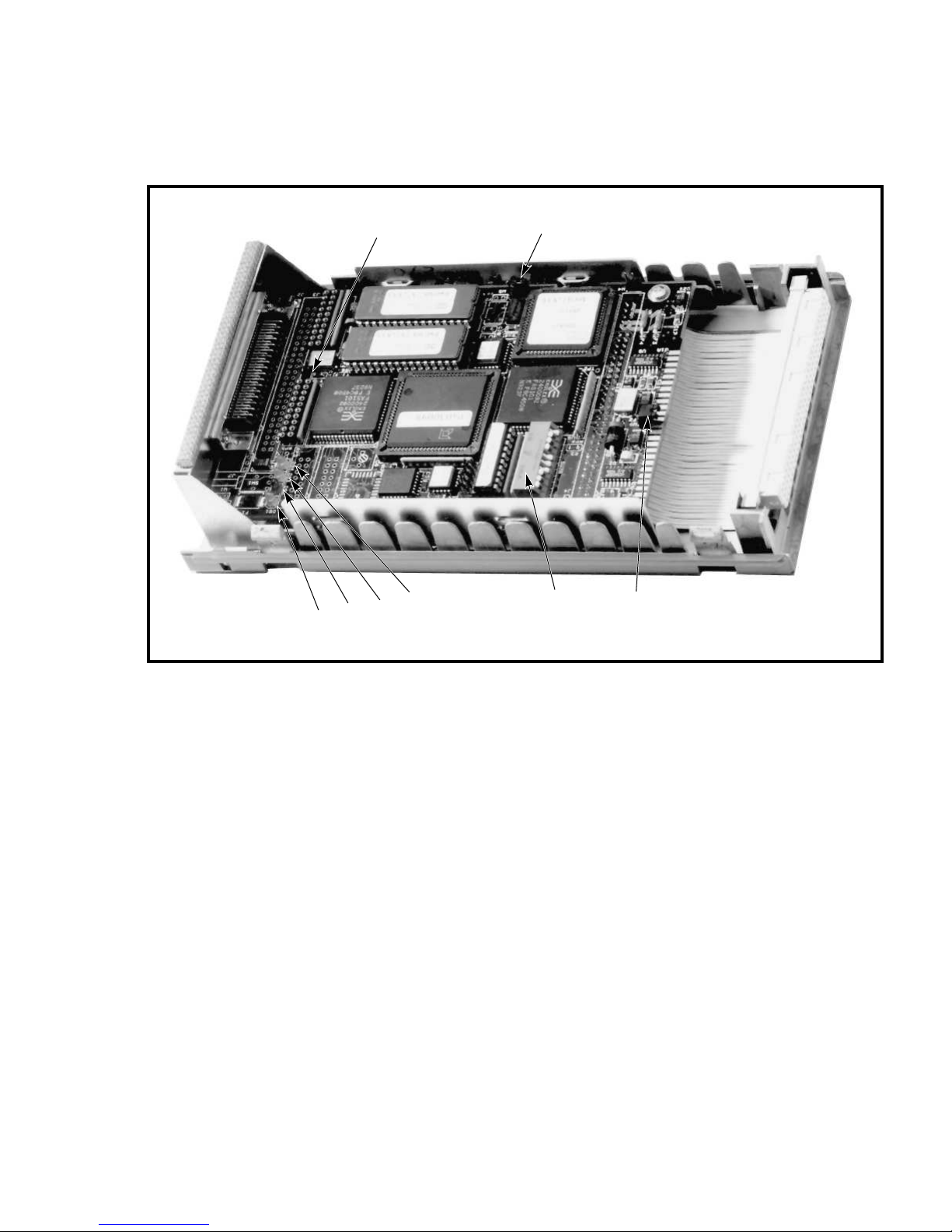
Figure 2–1 HSD05 Array Controller Module Board Layout
DS1
DS2
W8
DS3
DS4
W3
SW2
W9
CXO-4053A-PH
The functions of the switches and jumpers on the module board are given in the
following tables:
• Table 2–2 lists the jumper settings for the HSD05 array controller. These
settings need not be changed during a normal installation.
• Table 2–3 lists the switch sections in the device configuration switchpack
(SW2). You will need to set these switches according to the procedures given
in Section 2.4.
Preparing to Use the HSD05 Array Controller 2–3

Table 2–2 HSD05 Array Controller Module Board Jumpers
Jumper Definition
W1 Reserved
W2 Reserved
W3 EPROM size
W4 Wait state
W5 Reserved
W6 Reserved
W7 Reserved
W8 DSSI terminator power supplied by module
W9 SCSI terminator power supplied by module
Table 2–3 Device Configuration Switchpack (SW2) Sections
Section Definition Default
SW2–1 MSB of DSSI ID Open (DSSI ID = 0)
SW2–2 NSB of DSSI ID Open
SW2–3 LSB of DSSI ID Open
SW2–4 MSB of SCSI ID Closed (SCSI ID = 7)
SW2–5 NSB of SCSI ID Closed
SW2–6 LSB of SCSI ID Closed
SW2–7 Spare Open
SW2–8 Spare Open
SW2–9 Spare Open
SW2–10 Active SCSI termination Closed (terminators installed)
2.4 Setting the Device Configuration on the HSD05 Array Controller
This section contains the procedure to set the switches on the HSD05 array
controller module board prior to installation in the SBB shelf. To access the
switches, look through the slot in the back cover of the HSD05 array controller
and locate the configuration switchpack, as shown in Figure 2–2.
The device configuration switchpack contains 10 switch elements, divided into
DSSI ID and SCSI ID sections as shown in Figure 2–2. Refer to The NAME_
ALGRM Parameter for detailed information on the makeup of the MSCP/TMSCP
unit numbers.
2.4.1 DSSI ID
The DSSI port (J1) on the front panel connects the HSD05 array controller to a
standard DSSI bus device, such as a VAX 4000™ host computer.
2–4 Preparing to Use the HSD05 Array Controller

Figure 2–2 Device Configuration Switchpack
DSSI
NODE ID
SCSI
ID
NOT
USED
SCSI
TERMINATION
(OPEN)
(CLOSED)
CXO-4020A-MC
Selecting the DSSI ID
Each device on the DSSI bus requires a unique device address in the range of 0
through 7. DSSI ID 7 has the highest priority on the bus and DSSI ID 0 has the
lowest priority. The DSSI ID is factory set to 0; you may need to change this ID
to one that is currently not being used on your system.
Setting the DSSI ID
Table 2–4 lists the sections of SW2 and the corresponding settings for each DSSI
ID. On the switchpack, the closed position is with the switch in the down position,
and the open position is with the switch in the up position.
Preparing to Use the HSD05 Array Controller 2–5

Table 2–4 DSSI ID Switch Settings
DSSI
ID SW2–1 SW2–2 SW2–3
0 Open Open Open
1 Open Open Closed
2 Open Closed Open
3 Open Closed Closed
4 Closed Open Open
5 Closed Open Closed
6 Closed Closed Open
7 Closed Closed Closed
Use the following procedure to set the DSSI ID:
1. At the system console prompt, enter the console command SHOW DEVICE on
OpenVMS VAX systems, or SHOW CONFIG on OpenVMS AXP systems, to
determine the DSSI ID numbers currently active on the DSSI bus.
2. Select an unused DSSI ID number for the HSD05 array controller.
3. Refer to Figure 2–2 and Table 2–3 to locate the DSSI ID switches on the
device configuration switchpack.
4. Using a small blade screwdriver or similar tool, reach through the slot in the
rear panel of the HSD05 array controller, and set the switchpack to the DSSI
ID number selected in Step 2.
2.4.2 SCSI ID
The SCSI port (J2) plugs into the SBB shelf backplane when the HSD05 array
controller is installed in the shelf. This port must have a unique SCSI ID for that
SBB shelf.
Selecting the SCSI ID
The HSD05 array controller is factory set to SCSI ID = 7 to give it the highest
priority on the SCSI bus. The other devices in the configuration must have SCSI
ID numbers between 0 and 6. For normal operation, you should not need to reset
the SCSI ID.
Setting the SCSI ID
Table 2–5 lists the sections of SW2 and the corresponding sections used to set the
SCSI ID. On the switchpack, the closed position is with the switch in the down
position, and the open position is with the switch in the up position.
2–6 Preparing to Use the HSD05 Array Controller

Table 2–5 SCSI ID Switch Settings
SCSI
ID SW2–4 SW2–5 SW2–6
0 Open Open Open
1 Open Open Closed
2 Open Closed Open
3 Open Closed Closed
4 Closed Open Open
5 Closed Open Closed
6 Closed Closed Open
7 Closed Closed Closed
Use the following procedure to set the SCSI ID, if required:
1. Select an unused SCSI ID for the HSD05 array controller.
2. Refer to Figure 2–2 and Table 2–3 to locate the SCSI ID switches on the node
configuration switchpack.
3. Using a small blade screwdriver or similar tool, reach through the slot in the
rear panel of the HSD05 array controller and set the switchpack to the SCSI
ID number selected in Step 2.
2.4.3 Selecting Bus Termination
DSSI and SCSI bus rules require that these buses be terminated at both physical
ends.
The DSSI bus can be terminated externally by using a terminator on the
DSSI trilink connector (shown in Figure 2–3), supplied with the HSD05 array
controller. Because the HSD05 array controller typically occupies one end of the
DSSI bus, this terminator is normally installed. Make sure that the other end of
the DSSI bus is properly terminated.
The DSSI bus uses two types of connectors: either a microribbon
connector or a tab-and-socket connector. If you are connecting to a
KFMSA/KFMSB host adapter, the cable will have microribbon connectors
at both ends. All other host adapters use a tab-and-socket connector. The
trilink has two microribbon connectors.
Selecting a terminator on the SCSI bus is dependent on the exact configuration
of the SBB shelf in the chain of SCSI devices. The HSD05 array controller is
shipped with active SCSI bus termination enabled. When installed in SBB shelf
slot 0, it provides termination at the HSD05 array controller end of the SCSI bus.
Make sure that the other end of the SCSI bus is also terminated properly.
Refer to the StorageWorks documentation for the rules used to select terminations
on the SCSI bus. Appendix A contains diagrams of some typical installations of
the HSD05 array controller.
Note
Preparing to Use the HSD05 Array Controller 2–7

2.5 Installing the HSD05 Array Controller in an SBB Shelf
Before starting this procedure, verify that the SBB shelf receiving the HSD05
array controller is the correct one, and that it is permissible to change any SCSI
cables connected to JA1 and JB1 of the shelf to suit the planned configuration.
Figure 2–3 DSSI Trilink Connector
REAR VIEW
FRONT VIEW
CXO-3851A-MC
The HSD05 array controller should be installed in shelf slot 0. SCSI bus integrity
can be compromised if the HSD05 array controller is installed in any other slot
of a standard SBB shelf. Refer to the StorageWorks documentation for further
information on selecting an SBB slot and on cable configuration rules for the SBB
shelf.
Installation Procedure
Use the following procedure to install the HSD05 array controller in the SBB
shelf:
1. Remove power from the shelf by removing the input power cable(s) to the
power supply SBB(s) in the shelf. If there is only one power supply SBB in
the shelf, it will be in slot 7.
2. Remove all SCSI devices from the SBB shelf.
3. For single-shelf HSD05 array controller configurations, disconnect any cables
at JA1 and JB1 of the shelf.
4. For dual-shelf HSD05 array controller configurations, see Figure A–2 for a
diagram showing interconnected shelves.
5. Insert the HSD05 array controller into shelf slot 0.
6. Take all DSSI nodes off line to remove power from the DSSI bus that will be
connected to the HSD05 array controller.
2–8 Preparing to Use the HSD05 Array Controller

Make sure that the trilink connector pins are not bent or damaged before
installing it on the HSD05 array controller.
7. Install a DSSI trilink connector (part number 12–39921–02), shown in
Figure 2–3, at J1 on the front panel of the HSD05 array controller.
8. Connect the DSSI cables to the trilink connector as directed in either of the
the following:
• If the HSD05 array controller occupies one end of the DSSI bus, connect
the DSSI cable to one of the connectors on the trilink. Install a DSSI bus
terminator (part number 12–31281–01) on the other trilink connector.
• If the HSD05 array controller occupies a mid-point of the DSSI bus,
connect the DSSI bus cables from adjacent nodes to the trilink connectors.
The DSSI bus terminator is not used on the trilink in this configuration.
Appendix A shows several typical HSD05 array controller cable
configurations.
9. Restore power to the DSSI bus nodes, but do not boot the host systems at this
time.
2.6 Applying Power
CAUTION
Apply power to the SBB shelf and the HSD05 array controller as follows:
1. Connect the input power cable(s) to the power supply SBB(s) in the shelf.
2. Verify that the Shelf Status indicator on the power supply SBB is lit. If this
indicator is not lit, refer to the StorageWorks documentation to troubleshoot
the cause of the fault.
3. Verify that the following HSD05 array controller indicators (shown in
Figure 2–1), visible from top to bottom through the front panel louvers, are as
follows:
Indicator Color Status
DS4 Green On to show that termination power, supplied by either the
DS3 Green On to show that termination power, supplied by either the
DS2 Red Blinks for 15 seconds during module boot. If this indicator
DS1 Green Blinks during normal operation while the subsystem is
HSD05 array controller or the SBB shelf, is applied to the
SCSI bus
HSD05 array controller or the host bus, is applied to the
DSSI bus.
blinks for longer than 15 seconds, there is a device fault.
booted.
CAUTION
Device unit numbers as seen by the hosts must be unique through
the system or cluster containing the HSD05 array controller. If a unit
number is added that overlaps the unit number of another device on
another controller of a system or cluster, all the devices on the other
Preparing to Use the HSD05 Array Controller 2–9

controller can disappear. In this event, the unit number conflict should be
resolved, and controller power should then be cycled off/on to make the
devices available to the host system or cluster.
4. At the system console prompt, enter the console command SHOW DEVICE on
OpenVMS VAX systems, or SHOW CONFIG on OpenVMS AXP systems, to
verify that the HSD05 DSSI node address is on line to the host systems.
2.7 Setting Parameters for the HSD05 Array Controller
The OpenVMS diagnostic and utility protocol (DUP) utility provides a gateway
to modifying HSD05 array controller parameters. You can run this utility from
either the system console or from the OpenVMS system prompt.
Once a DUP connection to the HSD05 array controller is established, the onboard
PARAMS configuration utility is used to set and show HSD05 parameters.
Chapter 3 contains procedures for using the HSD05 onboard device and diagnostic
utility (UTILIT) during normal operation of the subsystem.
In the following sections, user input is shown in boldface type in the examples.
2.7.1 Starting PARAMS from the Console Prompt on OpenVMS VAX Systems
Use the following procedure to start PARAMS from the console prompt on
OpenVMS VAX systems:
1. At the console prompt, enter the SHOW DEVICE command as shown in the
following example:
>>> SHOW DEVICE
DSSI Node ID 0 (DSSI nodename)
DSSI NODE ID 5 (*)
UQSSP Disk Controller 0 (772150)
-DUA0 (RA82)
Ethernet Adapter
-ESA0 (08-00-2B-13-80-85)
This is the HSD05 array controller. The DSSI nodename is initially a
six-digit number. Do not confuse this number with the DSSI ID value.
2. Depending upon your installation, enter one of the following two command
lines to use the DUP utility to establish a connection to the HSD05 array
controller:
>>> SET HOST/DUP/DSSI a
Starting DUP server...
Copyright (C) 1994 Digital
HSD05 Serial No: 8
Firmware Rev. B1 (X36 )
DIRECT V1.0 D Dec 21 1993 16:59:31
PARAMS V1.0 D Dec 21 1993 16:59:31
UTILIT V1.0 D Dec 21 1993 16:59:31
End of directory
Task Name?
where a is the DSSI ID of the HSD05 array controller.
2–10 Preparing to Use the HSD05 Array Controller

You may have to explicitly specify the DSSI bus (0 or 1) to properly establish
a connection to the HSD05 array controller. In such cases use the following
command line:
>>> SET HOST/DUP/DSSI/BUS:n a
Starting DUP server...
Copyright (C) 1994 Digital
HSD05 Serial No: 8
Firmware Rev. B1 (X36 )
DIRECT V1.0 D Dec 21 1993 16:59:31
PARAMS V1.0 D Dec 21 1993 16:59:31
UTILIT V1.0 D Dec 21 1993 16:59:31
End of directory
Task Name?
where:
n is the DSSI bus ID number (0 or 1).
a is the DSSI ID for the HSD05 array controller.
3. At the ‘‘Task Name?’’ prompt, enter PARAMS. If you do not see the ‘‘Task
Name?’’ prompt, DUP has not established a connection to the HSD05 array
controller. In this event, see your system manager.
4. At the PARAMS prompt, see Section 2.7.3 to configure HSD05 parameters.
2.7.2 Starting PARAMS from the Console Prompt on OpenVMS AXP Systems
Use the following procedure to start PARAMS from the console prompt on
OpenVMS AXP systems:
1. At the console prompt, enter the SHOW CONFIG command as shown in the
following example:
>>>SHOW CONFIGURATION
Console V2.8-9900 VMS PALcode X5.37F, OSF PALcode X1.28F
CPU 0 P B2001-BA DECchip (tm) 21064-3
CPU1 Memory 0 Memory 1 Memory 2 Memory 3 P B2002-DA 128 MB
Ethernet 0 P 08-00-2B-32-E6-AB
Ethernet 1 P 08-00-2B-32-E6-AA
ID 0 ID 1 ID2 ID 3 ID 4 ID 5 ID 6 ID 7
A SCSI P RZ73 Host
B SCSI P RZ73 Host
C DSSI P RF73 RF72
Host
D DSSI P RF73 Host
E SCSI P TZ85 RRD42 Host
Futurebus+ P FBD0 Host
System Status Pass Type b to boot duc1.1.0.2.0
This display is a map of the attached devices and their SCSI/DSSI bus
addresses. The HSD05 array controller is displayed as device RF72. In
this example, the ID 4 column shows that the DSSI ID = 4, and row C
shows that the DSSI bus designation where the HSD05 resides is C.
Preparing to Use the HSD05 Array Controller 2–11

2. Enter the following command to use the DUP utility to establish a connection
to the HSD05 array controller:
>>> SET HOST -DUP d
where d is the appropriate port address identifier for the HSD05 array
controller.
The following command line shows an example of this entry:
>>> SET HOST -DUP PUC0.4.0.2.0
Starting DUP server...
Copyright (C) 1994 Digital
HSD05 Serial No: 8
Firmware Rev. B1 (X36 )
DIRECT V1.0 D Dec 21 1993 16:59:31
PARAMS V1.0 D Dec 21 1993 16:59:31
UTILIT V1.0 D Dec 21 1993 16:59:31
End of directory
Task?
3. At the ‘‘Task?’’ prompt, enter PARAMS. If you do not see the ‘‘Task?’’ prompt,
DUP has not established a connection to the HSD05 array controller. In this
event, see your system manager.
4. At the PARAMS prompt, see Section 2.7.3 to configure HSD05 parameters.
2.7.3 PARAMS Configuration Utility
The PARAMS configuration utility display shows the settings for HSD05 array
controller parameters. At the PARAMS prompt, enter SHOW /ALL to display the
current HSD05 parameters. When entering this command, a space is required
between the SHOW and /ALL qualifier. The meaning of each parameter is given
in Table 2–6.
HSD05 array controller operating parameters are initialized by manufacturing.
Depending upon the specific configuration of your system or cluster, suggested
parameters that may need to be set include:
• NODENAME
• DISK_ALCS
• TAPE_ALCS
• UNIT_OFFSET
Table 2–6 PARAMS Configuration Utility HSD05 Array Controller Parameters
Parameter
Name Definition
NODENAME HSD05 node name. This value must be unique among all systems
in the VAXcluster™ system. The string cannot include the dollar
sign ($), or underscore (_) characters and should be no longer than
eight characters. The factory default for the node name is a unique
six-digit number.
(continued on next page)
2–12 Preparing to Use the HSD05 Array Controller

Table 2–6 (Cont.) PARAMS Configuration Utility HSD05 Array Controller
Parameters
Parameter
Name Definition
SYSTEMID Specifies the lower order 32 bits of the 48-bit system identification
DISK_ALCS Determines the device allocation class for all disk devices connected
TAPE_ALCS Determines the device allocation class for all tape devices connected
INTERVAL Controls the rate at which SCSI device scanning is done. This value
NUMPOLL Controls the number of SCSI devices to look for during each
UNIT_OFFSET Helps to differentiate devices when a system has two DSSI buses.
SYNC_RATE The rate in MHz that data is transferred during the data
MAX_HOSTS Determines the maximum number of hosts with which the HSD05
FASTSCAN Reduces the SCSI SELECT timeout to a much smaller value, with
SCANNING Enables/disables the HSD05 array controller’s ability to scan for
DISCONNECT Enables/disables the ability to disconnect all SCSI devices connected
number. The factory default for this identifier is the same as
specified by the NODENAME parameter.
to HSD05 array controller. If disks are to be served to other nodes
within the VAXcluster, this parameter must be non-zero and match
the ALLOCLASS SYSGEN parameter on connected systems. The
factory default for this parameter is zero.
to the HSD05 array controller. If tapes are to be served to other
nodes within the VAXcluster, this parameter must be non-zero and
match the ALLOCLASS SYSGEN parameter on connected systems.
The factory default for this parameter is zero.
is only used if SCANNING is enabled. The factory default for this
parameter is 60 seconds.
INTERVAL. This parameter is currently not implemented but
may be activated in a future revision of the firmware. The factory
default for this parameter is 7, which scans for all available units at
each interval.
Unit offset is specified as the value to be used in the thousands
position of the MSCP unit ID, such as x for DIAx210. This offset is
automatically created by the system. The unit offset values must
be unique for each DSSI bus on the system. The factory default for
this parameter is 0.
transmission phase between target and host. The factory default for
this parameter is 7 MHz.
array controller will communicate. This parameter is primarily
used for disk and tape credit allotment. For best performance, set
this parameter to the maximum number of hosts to be used. Digital
supports up to three hosts (the factory default) in a multihost
HSD05 array controller configuration.
the default timeout set at 250 milliseconds. This parameter is
currently not implemented. The factory default for this parameter
is 0 (disabled).
newly connected devices. If scanning is disabled, the HSD05 array
controller only does one scan for devices at power up, and will not
look for new devices every INTERVAL seconds. The factory default
for this parameter is 1.
to the HSD05 array controller. When only one device is connected
to the HSD05 array controller, this parameter should be disabled
for better performance. The factory default for this parameter is 1.
(continued on next page)
Preparing to Use the HSD05 Array Controller 2–13

Table 2–6 (Cont.) PARAMS Configuration Utility HSD05 Array Controller
Parameters
Parameter
Name Definition
POWERONRST Enables/disables issuing a SCSI BUS RESET command when the
TRYSYNC Enables/disables synchronous negotiation when a SCSI device is
SPIN_DOWN Enables/disables the ability of the HSD05 array controller to
TAGGED_CMD Enables/disables simple tag queuing. The factory default for this
TRUNCATE This parameter truncates the number of blocks to be divisible
DEVICE_TYPE This parameter applies to disk drives only. When disabled (set
IMMEDIATE When enabled, this parameter causes the IMMEDIATE bit in the
CMD_P3 Determines the type of transmission used on the DSSI bus for
TMARKSEARCH Enables fast tape mark searching. Because some tape drives
SHORT_TMARK Enables/disables writing short filemarks on Exabyte® devices.
system is turned on. The factory default for this parameter is 1
(enabled).
initialized. For very short cables, synchronous negotiation can be
disabled for better performance in ASYNC mode rather than SYNC
mode. The factory default for this parameter is 1 (enabled).
spin down drives or eject media when the operating system
issues a spin down command, such as the OpenVMS command
DISMOUNT/UNLOAD. The factory default for this parameter is 1
(enabled).
parameter is 1 (enabled).
by 126. The factory default for this parameter is 1. This default
supports faster OpenVMS volume shadowing catch-up time. A value
of 0 selects no truncation for compatibility with other third-party
units.
to 0), the device type reported by the HSD05 array controller to
the OpenVMS operating system is an RA82™ disk drive. When
enabled, the HSD05 array controller reports the RF72™ device
type. The device type reported to the host does not affect the
accessible disk space. The factory default for this parameter is 1
(enabled).
SCSI START and STOP commands to be set. Note that when
IMMEDIATE is set to 0, the OpenVMS prompt does not return
until the drive’s media is ejected or the drive has spun down. The
factory default for this parameter is 1 (enabled).
single host configurations only: 0 for standard and 1 for fast mode.
This is a hidden parameter that is not displayed by the PARAMS
SHOW /ALL, SHOW /SCSI, or SHOW /SCS commands. To display
this parameter value, use the SHOW CMD_P3 command in the
PARAMS utility. The factory default for this parameter is 1 (fast
mode).
perform slowly while looking for tape marks during operations
on large space records, a skip tapemark is done instead. Because
the device does not report the number of records skipped between
tapemarks, the position (object) count is not correct when this
parameter is enabled. The factory default for this parameter is 0
(disabled).
When disabled, all filemarks are written as large filemarks. The
factory default for this parameter is 1 (enabled).
(continued on next page)
2–14 Preparing to Use the HSD05 Array Controller

Table 2–6 (Cont.) PARAMS Configuration Utility HSD05 Array Controller
Parameters
Parameter
Name Definition
WT_PROTECTED Enables/disables write protection for each SCSI ID. When disabled
ONLINE Controls whether devices are on line or off line to the host. This
NAME_ALGRM This parameter is fully described in The NAME_ALGRM Parameter.
SCSI_ID_X Used in conjunction with the NAME_ALGRM parameter to set
(set to 0), it allows read-write access to a SCSI ID, and when
enabled, it restricts access to read only. This parameter is in the
form of a boolean matrix, with the leftmost position representing a
SCSI ID of 7, and the rightmost position representing a SCSI ID
of 0. For example, a WT_PROTECTED setting of 00000001 allows
read-write access to SCSI IDs 1 through 7 and read only access to
SCSI ID 0. The factory default for this parameter is 00000000 (no
devices write protected).
parameter is in the form of a boolean matrix, with the leftmost
position representing SCSI ID=7, and the rightmost position
representing SCSI ID=0. For example, a WT_PROTECTED setting
of 10000000 sets SCSI IDs 0 through 6 off line and SCSI ID 7 on
line. The factory default for this parameter is 11111111 (all devices
on line).
alternative device names for each SCSI ID.
The NAME_ALGRM Parameter
The NAME_ALGRM parameter toggles between the HSD05 array controller’s
standard device naming convention and an alternative convention based upon the
TMSCP/MSCP unit number. When NAME_ALGRM is set to the default of 0, the
HSD05 array controller uses its standard naming algorithm, which assigns a unit
number composed of the DSSI ID of the HSD05 array controller according to the
following parameters:
• Unit offset—A unique number (0 - 9) for each host DSSI bus. This
parameter can be used to modify bus numbering conflicts in multiple DSSI
bus configurations.
• DSSI ID—The DSSI device address for the HSD05 array controller.
• SCSI ID—The SCSI device address for the storage device. This is set by
either the device’s shelf slot position or by ID switches on the device.
• SCSI logical unit number—The device address of a subdevice attached to a
SCSI device identified by SCSI ID x.
Setting NAME_ALGRM to 1 activates the alternative naming algorithm, which
assigns a unit number in conjunction with the SCSI_ID_X parameter. These two
conventions are summarized as follows:
Preparing to Use the HSD05 Array Controller 2–15

NAME_ALGRM
Setting
0 wxyz 1234 where: w = 1, x = 2, y = 3, z = 4
1 scsi_id_x + ((w + 1) * z) Assuming w = 1, z = 1, and the scsi_id_x parameter
Formula for MSCP/TMSCP
Unit Number
1
Example
values are as follows:
1
where:
w = UNIT_OFFSET parameter
x = DSSI ID
y = SCSI ID
z = SCSI logical unit number
SCSI ID
0 0 2
1 10 12
2 20 22
3 30 32
4 40 42
5 50 52
6 60 62
7 70 72
SCSI_ID_X MSCP/TMSCP Unit Number
2.7.4 Display Device Parameters Using the PARAMS Config Utility
To display the device parameters, enter SHOW /ALL at the PARAMS prompt; a
space is required between the SHOW and /ALL qualifier. The default settings are
as follows:
PARAMS> SHOW /ALL
Parameter Name Active Min. Max. Units
---------------- ------- ----- ------- ------NODENAME "xxxxxx" 1 8 Ascii
SYSTEMID xxxxxx 1 268435456 DecimalNum
DISK_ALCS 0 0 255 DecimalNum
TAPE_ALCS 0 0 255 DecimalNum
INTERVAL 60 0 32768 Seconds
NUMPOLL 7 0 7 DecimalNum
UNIT_OFFSET 0 0 9 DecimalNum
SYNC_RATE 7 1 10 DecimalNum
MAX_HOSTS 4 1 7 DecimalNum
FASTSCAN 0 0 1 Boolean
SCANNING 1 0 1 Boolean
POWERONRST 1 0 1 Boolean
TRYSYNC 1 0 1 Boolean
SPIN_DOWN 1 0 1 Boolean
TAGGED_CMD 1 0 1 Boolean
TRUNCATE 1 0 1 Boolean
DEVICE_TYPE 1 0 1 Boolean
IMMEDIATE 1 0 1 Boolean
TMARKSEARCH 0 0 1 Boolean
SHORT_TMARK 1 0 1 Boolean
WT_PROTECTED 00000000 0 1 BooleanM
2–16 Preparing to Use the HSD05 Array Controller

ONLINE 11111111 0 1 BooleanM
NAME_ALGRM 0 0 255 DecimalNum
SCSI_ID_0 0 0 9999 DecimalNum
SCSI_ID_1 10 0 9999 DecimalNum
SCSI_ID_2 20 0 9999 DecimalNum
SCSI_ID_3 30 0 9999 DecimalNum
SCSI_ID_4 40 0 9999 DecimalNum
SCSI_ID_5 50 0 9999 DecimalNum
SCSI_ID_6 60 0 9999 DecimalNum
SCSI_ID_7 70 0 9999 DecimalNum
2.7.5 Set Device Parameters Using the PARAMS Configuration Utility
Use the following procedure to set new device parameters:
1. At the PARAMS prompt, enter the parameters you wish to change, as shown
in the following example:
PARAMS> SET NODENAME HSD1
PARAMS> SET DISK_ALCS 10
In this example, the NODENAME has been changed to HSD1 and the DISK_
ALCS parameter set to 10.
2. Enter the SHOW /ALL command to display your changed parameters:
PARAMS> SHOW /ALL
Parameter Name Active Min. Max. Units
---------------- ------- ----- ------- ------NODENAME "HSD1 " 1 8 Ascii
SYSTEMID 131072 1 268435456 DecimalNum
DISK_ALCS 10 0 255 DecimalNum
TAPE_ALCS 0 0 255 DecimalNum
INTERVAL 60 0 32768 Seconds
.
.
.
SCSI_ID_4 40 0 9999 DecimalNum
SCSI_ID_5 50 0 9999 DecimalNum
SCSI_ID_6 60 0 9999 DecimalNum
SCSI_ID_7 70 0 9999 DecimalNum
3. Save the changes to nonvolatile memory with the following command:
PARAMS> WRITE
4. Reboot the HSD05 array controller to use the new parameters:
PARAMS> RESTART
5. Install the SCSI devices in the SBB shelf, making sure that the SCSI IDs
are unique for each HSD05, and that they do not overlap each other or the
SCSI address of the HSD05 array controller (default = 7). You do not need to
remove power from the SBB shelf for this step.
6. Check that the Device Fault indicators on the front panels of the storage
unit SBBs are not lit. If any indicator is lit, refer to the StorageWorks
documentation to troubleshoot the cause of the fault.
Preparing to Use the HSD05 Array Controller 2–17

7. At the system console prompt, enter the console command SHOW DEVICE
on OpenVMS VAX systems or OpenVMS AXP systems to verify that the SCSI
devices are available to the host systems.
CAUTION
The HSD05 array controller returns a limited set of device type
identification names to the host. All attached tape drives are identified
as TU81 (MUAxxx). All attached disk drives are normally identified as
RF72 (DIAxxx); this can be changed to identification as RA82 (DUAxxx)
by setting the HSD05 parameter DEVICE_TYPE to 0. These device types
as reported to the host do not affect actual accessible device storage space.
Due to device geometry differences, a disk drive served by the HSD05
array controller cannot be part of a shadow set with true RF72, or any
other DSSI disk drives. Shadow sets using HSD05 array controller-served
disk drives must be of the same SCSI device type; for example, RZ26,
RZ26L, or RZ28 disk drives.
8. Reboot the host systems to update the host device tables to the new settings
for the HSD05 array controller and attached devices. Verify that any
parameter changes are shown at both the console and within the OpenVMS
operating system.
2–18 Preparing to Use the HSD05 Array Controller

Operating the HSD05 Array Controller
This chapter contains procedures used in the everyday operation of the HSD05
array controller, including how to run the onboard utilities, troubleshooting
procedures, and a remove and replace procedure for the HSD05 array controller.
Whenever a host on a DSSI bus containing an HSD05 array controller
is rebooted, Digital recommends that the HSD05 array controller is also
reset to ensure consistent reporting of HSD05-served devices to the host.
This can be accomplished by issuing a ‘‘restart’’ command in the PARAMS
configuration utility, or simply by removing and restoring power to the
HSD05-served shelf.
3.1 HSD05 Device Utilities
The HSD05 onboard utilities (UTILIT) allow you to monitor, format, qualify, and
exercise SCSI devices from the OpenVMS operating system. The onboard utilities
are accessed through the diagnostic and utility protocol (DUP) server, either
through the system console or from the OpenVMS prompt.
3
CAUTION
In this chapter, user input is shown in boldface type in the examples.
CAUTION
The HSD05 array controller returns a limited set of device type
identification names to the host. All attached tape drives are identified
as TU81 (MUAxxx). All attached disk drives are normally identified as
RF72 (DIAxxx); this can be changed to identification as RA82 (DUAxxx)
by setting the HSD05 parameter DEVICE_TYPE to 0. These device types
as reported to the host do not affect actual accessible device storage space.
Due to device geometry differences, a disk drive served by the HSD05
array controller cannot be part of a shadow set with true RF72, or any
other DSSI disk drives. Shadow sets using HSD05 array controller-served
disk drives must be of the same SCSI device type; for example, RZ26,
RZ26L, or RZ28 disk drives.
Operating the HSD05 Array Controller 3–1

3.1.1 Starting UTILIT from the Console Prompt on OpenVMS VAX Systems
Use the following procedure to start UTILIT from the console prompt on
OpenVMS VAX systems:
1. At the console prompt, enter the SHOW DEVICE command as shown in the
following example:
>>> SHOW DEVICE
DSSI Node ID 0 (DSSI nodename)
-DIA200 (RF72)
-DIA210 (RF72)
-DIA250 (RF72)
DSSI NODE ID 5 (*)
UQSSP Disk Controller 0 (772150)
-DUA0 (RA82)
Ethernet Adapter
-ESA0 (08-00-2B-13-80-85)
This is the HSD05 array controller. The DSSI nodename is initially a
six-digit number. Do not confuse this number with the DSSI ID value.
2. Depending upon your installation, enter one of the following two command
lines to use the DUP utility to establish a connection to the HSD05 array
controller:
>>> SET HOST/DUP/DSSI a
Starting DUP server...
Copyright (C) 1994 Digital
HSD05 Serial No: 8
Firmware Rev. B1 (X36 )
DIRECT V1.0 D Dec 21 1993 16:59:31
PARAMS V1.0 D Dec 21 1993 16:59:31
UTILIT V1.0 D Dec 21 1993 16:59:31
End of directory
Task Name?
where a is the DSSI ID of the HSD05 array controller.
You may have to explicitly specify the DSSI bus (0 or 1) to properly establish
a connection to the HSD05 array controller. In such cases, use the following
command line:
>>> SET HOST/DUP/DSSI/BUS:n a
Starting DUP server...
Copyright (C) 1994 Digital
HSD05 Serial No: 8
Firmware Rev. B1 (X36 )
DIRECT V1.0 D Dec 21 1993 16:59:31
PARAMS V1.0 D Dec 21 1993 16:59:31
UTILIT V1.0 D Dec 21 1993 16:59:31
End of directory
Task Name?
where:
n is the DSSI bus ID number (0 or 1).
a is the DSSI ID for the HSD05 array controller.
3–2 Operating the HSD05 Array Controller

3. At the ‘‘Task Name?’’ prompt, enter UTILIT. If you do not see the ‘‘Task
Name?’’ prompt, DUP has not established a connection to the HSD05 array
controller. In this event, see your system manager.
4. At the UTILIT prompt, refer to Section 3.1.4 to configure HSD05 parameters.
3.1.2 Starting UTILIT from the Console Prompt on OpenVMS AXP Systems
Use the following procedure to start UTILIT from the console prompt on
OpenVMS AXP systems:
1. At the console prompt, enter the SHOW CONFIG command as shown in the
following example:
>>>SHOW CONFIGURATION
Console V2.8-9900 VMS PALcode X5.37F, OSF PALcode X1.28F
CPU 0 P B2001-BA DECchip (tm) 21064-3
CPU1 Memory 0 Memory 1 Memory 2 Memory 3 P B2002-DA 128 MB
Ethernet 0 P 08-00-2B-32-E6-AB
Ethernet 1 P 08-00-2B-32-E6-AA
A SCSI P RZ73 Host
B SCSI P RZ73 Host
C DSSI P RF73 RF72
D DSSI P RF73 Host
E SCSI P TZ85 RRD42 Host
Futurebus+ P FBD0 Host
System Status Pass Type b to boot duc1.1.0.2.0
This display is a map of the attached devices and their SCSI/DSSI bus
addresses. The HSD05 array controller is displayed as device RF72. In
this example, the ID 4 column shows that the DSSI ID = 4, and row C
shows that the DSSI bus designation is C.
ID 0 ID 1 ID2 ID 3 ID 4 ID 5 ID 6 ID 7
Host
2. Enter the following command to use the DUP utility to establish a connection
to the HSD05 array controller.
>>> SET HOST -DUP d
where d is the appropriate port address identifier for the HSD05 array
controller.
The following command line shows an example of this entry:
>>> SET HOST -DUP PUC0.4.0.2.0
Starting DUP server...
Copyright (C) 1994 Digital
HSD05 Serial No: 8
Firmware Rev. B1 (X36 )
DIRECT V1.0 D Dec 21 1993 16:59:31
PARAMS V1.0 D Dec 21 1993 16:59:31
UTILIT V1.0 D Dec 21 1993 16:59:31
End of directory
Task?
Operating the HSD05 Array Controller 3–3

3. At the ‘‘Task?’’ prompt, enter UTILIT. If you do not see the ‘‘Task?’’ prompt,
DUP has not established a connection to the HSD05 array controller. In this
event, see your system manager.
4. At the UTILIT prompt, refer to Section 3.1.4 to configure HSD05 parameters.
3.1.3 Starting the UTILIT Configuration Utility from the OpenVMS Prompt
You can start the UTILIT configuration utility from the OpenVMS prompt if both
of the following are true:
• You have the appropriate system manager privileges on the host system.
• The DUP utility on your system has been started.
Activate the DUP server and use the following procedure to start the UTILIT
utility:
1. On OpenVMS VAX systems, connect to the DUP server as follows:
$ MC SYSGEN CONNECT DUP_server/NOADAPTER
where DUP_server is the system DUP server and is typically ‘‘FYA0:’’.
On OpenVMS AXP systems, connect to the DUP server as follows:
$ MC SYSMAN IO CONNECT DUP_server/NOADAPTER/DRIVER=SYS$FDRIVER
where DUP_server is the system DUP server and is typically ‘‘FYA0:’’.
2. Enter the following to start the UTILIT configuration utility:
$ SET HOST/DUP/TASK=UTILIT/SERVER=MSCP$DUP n
Copyright (C) 1994 Digital
DIRECT V1.0 D Dec 21 1993 16:59:31
PARAMS V1.0 D Dec 21 1993 16:59:31
UTILIT V1.0 D Dec 21 1993 16:59:31
End of directory
where n is the DSSI nodename. See your system manager if you have
difficulty after entering this command line.
3. At the UTILIT prompt, refer to Section 3.1.4 to configure the HSD05
parameters.
HSD05 Serial No: 8
Firmware Rev. B1 (X36 )
UTILIT>
3.1.4 UTILIT Device Utility Commands
This section lists the UTILIT device commands and describes the action
performed by each command.
3.1.4.1 The HELP Command
The HELP command lists the onboard utilities command and the proper syntax
for each command, as shown in Example 3–1.
3–4 Operating the HSD05 Array Controller

Example 3–1 HELP Commands and Syntax
UTILIT> HELP
HELP
SHOW [device_name] | [/ALL]
SELECT device_name
DESELECT device_name
ABORT device_name
- Disk Commands FORMAT device_name
QUALIFY device_name [/WRITE]
DISKTEST device_name [/WRITE]
- Tape Commands TAPETEST device_name
UTILIT>
The symbol device_name refers to a valid MSCP/TMSCP™ device label for either
a direct access or sequential access device. Direct access devices, such as disk
drives, are specified with the ‘‘DIA’’ or ‘‘DUA’’ prefix to the device label, for
example, ‘‘DIA100’’. Sequential access devices, such as tape drives, are specified
with the ‘‘MUA’’ prefix, for example, ‘‘MUA120’’.
3.1.4.2 The SHOW Command
The SHOW command displays device information for either the device specified
by the device_name or for all devices by specifying the /ALL qualifier, as shown in
Example 3–2
Example 3–2 SHOW Command Display
UTILIT> SHOW DIA220
DeviceSIDVendorModelRevDev StatMaint OperMaint Status
------------------------------------------------------------------------DIA220 2-0 DEC RZ28 435E MAINT DISKTEST IN PROGRESS
UTILIT> SHOW /ALL
Device SID Vendor Model Rev Dev Stat Maint Oper Maint Status
------------------------------------------------------------------------MUA210 1-0 DEC TLZ06 0491 MAINT IDLE READY
DIA220 2-0 DEC RZ28 435E MAINT IDLE READY
MUA240 4-0 DEC TLZ6 0491 AVAILABLE
DIA260 6-0 DEC RZ26 329A AVAILABLE
UTILIT>
Device is the MSCP or TMSCP device name.
SID is the SCSI ID in the form target-logical unit number (LUN).
Vendor is the first seven characters of the manufacturer’s name.
Model is the first seven characters of the manufacturer’s model name.
Rev is the manufacturer’s firmware revision code.
Dev Stat is the current device status.
Maint Oper is the UTILIT maintenance operation.
Maint Status is the UTILIT maintenance operation status.
Operating the HSD05 Array Controller 3–5

3.1.4.3 The SELECT Command
The SELECT command is used to specify a device for maintenance before you
perform a format, qualify, or exercise operation.
Use the SHOW command to determine if the device is AVAILABLE to the HSD05
array controller. Devices that are listed as being OFFLINE or ONLINE to the
HSD05 array controller cannot be selected.
When a device is selected, its operational status becomes MAINT and the device
is not available to the OpenVMS operating system.
Command Syntax
The following is the syntax of the SELECT command:
SELECT device_name
The symbol device_name refers to a valid MSCP/TMSCP device label for either
a direct access or sequential access device. Direct access devices, such as disk
drives, are specified with the ‘‘DIA’’ or ‘‘DUA’’ prefix to the device label, for
example, ‘‘DIA100’’. Sequential access devices, such as tape drives, are specified
with the ‘‘MUA’’ prefix, for example, ‘‘MUA120’’.
Example 3–3 is an example of the SELECT operation display.
Example 3–3 SELECT Operation Display
UTILIT> SELECT DIA100
DeviceSIDVendorModelRevDev StatMaint OperMaint Status
------------------------------------------------------------------------DIA220 2-0 DEC RZ28 435E MAINT IDLE READY
UTILIT>
Device is the MSCP device name.
SID is the SCSI ID (target/lun).
Vendor is the first seven characters of the manufacturer’s name.
Model is the first seven characters of the manufacturer’s model name.
Rev is the manufacturer’s firmware revision code.
Dev Stat is the current device status.
Maint Oper is the UTILIT maintenance operation.
Maint Status is the UTILIT maintenance operation status.
3.1.4.4 The DESELECT Command
The DESELECT command deselects the devices that were selected for
maintenance by the UTILIT command SELECT. The deselected devices are
then returned to the AVAILABLE state.
3–6 Operating the HSD05 Array Controller

Command Syntax
The following is the syntax of the DESELECT command:
DESELECT device_name
The symbol device_name refers to a valid MSCP/TMSCP device label for either
a direct access or sequential access device. Direct access devices, such as disk
drives, are specified with the ‘‘DIA’’ prefix to the device label, for example,
‘‘DIA100’’. Sequential access devices, such as tape drives, are specified with
the ‘‘MUA’’ prefix, for example, ‘‘MUA120’’.
Example 3–4 is an example of the DESELECT command.
Example 3–4 DESELECT Command
UTILIT> DESELECT DIA100
UTILIT>
3.1.4.5 The ABORT Command
Use the ABORT command to terminate the QUALIFY, DISKTEST, and
TAPETEST operations. These operations normally run until stopped with the
ABORT command or by powering off the HSD05 array controller.
Command Syntax
The following is the syntax of the ABORT command:
The symbol device_name refers to a valid MSCP/TMSCP device label for either
a direct access or sequential access device. Direct access devices, such as disk
drives, are specified with the ‘‘DIA’’ prefix to the device label, for example,
‘‘DIA100’’. Sequential access devices, such as tape drives, are specified with
the ‘‘MUA’’ prefix, for example, ‘‘MUA120’’.
Example 3–5 is an example of the ABORT command.
Example 3–5 ABORT Command
3.1.4.6 FORMAT
After a device is selected with the SELECT command, you can use the FORMAT
command to perform a format operation.
ABORT device_name
UTILIT> ABORT DIA100
UTILIT>
Operating the HSD05 Array Controller 3–7

Command Syntax
The following is the syntax of the FORMAT command:
FORMAT device_name
The symbol device_name refers to a valid MSCP device label for a direct access
device. Direct access devices, such as disk drives, are specified with the ‘‘DIA’’
prefix to the device label, for example, ‘‘DIA100’’.
Command Description
You are prompted to confirm the format operation on the selected drive.
Answering ‘‘N’’ or ‘‘NO’’ aborts the operation with no change to the data on
the device. Answering ‘‘Y’’ or ‘‘YES’’ to this prompt starts the format operation on
the device.
The FORMAT command does not display a completion message. You can
monitor the format operation by periodically entering the SHOW command or
by observing the device’s activity indicator. After formatting the device, you
should run one or more qualification passes with the QUALIFY command.
Once started, you cannot abort the FORMAT operation. Example 3–6 shows of a
FORMAT operation display:
Example 3–6 FORMAT Operation Display
UTILIT> FORMAT DIA100
DeviceSIDVendorModelRevDev StatMaint OperMaint Status
------------------------------------------------------------------------DIA220 2-0 DEC RZ28 435E MAINT IDLE READY
FORMAT will destroy all data on this device. Are you sure (Y/N)? YES
UTILIT>
Device is the MSCP device name.
SID is the SCSI ID (target/lun).
Vendor is the first seven characters of the manufacturer’s name.
Model is the first seven characters of the manufacturer’s model name.
Rev is the manufacturer’s firmware revision code.
Dev Stat is the current device status.
Maint Oper is the UTILIT maintenance operation.
Maint Status is the UTILIT maintenance operation status.
3.1.4.7 The QUALIFY Command
You should run one or more qualification passes with the QUALIFY command
after a drive is formatted. The device to be qualified must first be selected with
the SELECT command.
3–8 Operating the HSD05 Array Controller

Command Syntax
The following is the syntax of the QUALIFY command:
QUALIFY device_name [/write]
The symbol device_name refers to a valid MSCP device label for a direct access
device. Direct access devices, such as disk drives, are specified with the ‘‘DIA’’
prefix to the device label, for example, ‘‘DIA100’’. The /WRITE qualifier selects a
write-read qualify operation.
Command Description
The QUALIFY command can run either read-only or write-read (using the
/WRITE qualifier). The write-read qualification operation consists of writing
sequential 32-kilobyte chunks of data to the device and then reading it back.
This sequence repeats until all logical blocks on the device have been written and
read. Bad blocks are replaced and retested in a write-read qualify operation. You
should use the write-read qualifier for newly formatted drives.
Running QUALIFY in the read-only mode verifies media readability and
consistency, but does not alter any drive data.
You are prompted to confirm the qualify operation on the selected device.
Answering ‘‘N’’ or ‘‘NO’’ aborts the operation with no change to the data on
the device. Answering ‘‘Y’’ or ‘‘YES’’ to this prompt starts the qualify operation on
the device.
Terminating the Test
QUALIFY runs until it is terminated with the ABORT command or until the
HSD05 array controller is powered off. The number of passes made is displayed
on a pass counter.
Example 3–7 shows a write-read qualification run using the QUALIFY
command.
Example 3–7 Write-Read Qualification Run Using the QUALIFY Command
UTILIT> QUALIFY DIA100 /WRITE
DeviceSIDVendorModelRevDev StatMaint OperMaint Status
------------------------------------------------------------------------DIA220 2-0 DEC RZ28 435E MAINT IDLE READY
QUALIFY will destroy all data on this device. Are you sure (Y/N)? YES
UTILIT>
Device is the MSCP device name.
SID is the SCSI ID (target/lun).
Vendor is the first seven characters of the manufacturer’s name.
Model is the first seven characters of the manufacturer’s model name.
Rev is the manufacturer’s firmware revision code.
Dev Stat is the current device status.
Maint Oper is the UTILIT maintenance operation.
Operating the HSD05 Array Controller 3–9

Maint Status is the UTILIT maintenance operation status.
3.1.4.8 The DISKTEST Command
The DISKTEST command performs an exercise on the selected disk device. You
should run DISKTEST on all newly formatted and qualified devices. The device
to be exercised must first be selected with the SELECT command.
Command Syntax
The following is the syntax of the DISKTEST command:
DISKTEST device_name [/write]
The symbol device_name refers to a valid MSCP device label for a direct access
device. Disk drives are specified with the ‘‘DIA’’ prefix to the device label. The
/WRITE qualifier selects a write-read disktest operation.
Command Description
The DISKTEST command can run either read-only or write-read (using the
/WRITE qualifier) tests. The write-read DISKTEST operation consists of writing
to randomly selected logical blocks and verifying the data. This sequence repeats
until all logical blocks on the device have been written and read, then the test
begins again until the ABORT command is entered to terminate the DISKTEST.
You must perform a write-read disktest to write data to the disk before you
perform the read-only disktest.
You are prompted to confirm the DISKTEST operation on the selected drive.
Answering ‘‘N’’ or ‘‘NO’’ aborts the operation with no change to the data on the
device. Answering ‘‘Y’’ or ‘‘YES’’ to this prompt starts the DISKTEST on the
device.
Running the DISKTEST operation with the /WRITE qualifier replaces media
errors when encountered. If other types of errors occur, the test is stopped and
the error condition is displayed in the Maint Status field of the display.
Terminating the Test
The DISKTEST test operation runs until it is terminated with the ABORT
command or until the HSD05 array controller is powered off.
Example 3–8 shows a write-read qualification run.
Example 3–8 Write-Read Qualification Run Using the DISKTEST Command
UTILIT> DISKTEST /WRITE DIA220
DeviceSIDVendorModelRevDev StatMaint OperMaint Status
------------------------------------------------------------------------DIA220 2-0 DEC RZ28 435E MAINT IDLE READY
DISKTEST will overwrite some or all data on this device. Are you sure (Y/N)? YES
Initiating Disk Test
UTILIT>
Device is the MSCP device name.
SID is the SCSI ID (target/lun).
Vendor is the first seven characters of the manufacturer’s name.
3–10 Operating the HSD05 Array Controller

Model is the first seven characters of the manufacturer’s model name.
Rev is the manufacturer’s firmware revision code.
Dev Stat is the current device status.
Maint Oper is the UTILIT maintenance operation.
Maint Status is the UTILIT maintenance operation status.
3.1.4.9 The TAPETEST Command
This command performs a tape exercise on the selected tape device. This test
requires enough tape to accommodate 10 megabytes of 1-kilobyte blocks. The
device to be exercised must first be selected with the SELECT command.
Command Syntax
The following is the syntax of the TAPETEST command:
TAPETEST device_name
The symbol device_name refers to a valid TMSCP device label for a direct access
or sequential access device. Tape drives are specified with the ‘‘MUA’’ prefix to
the device label.
Command Description
The TAPETEST exercise consists of writing, rewinding, and reading each section
of tape, up to but not including a filemark. Block sizes start at 32 kilobytes and
are halved on each successive write/rewind/read pass. The test is restarted when
the block size reaches 1 kilobyte.
You are prompted to confirm the TAPETEST operation on the selected drive.
Answering ‘‘N’’ or ‘‘NO’’ aborts the operation with no change to the data on the
device. Answering ‘‘Y’’ or ‘‘YES’’ to this prompt starts the TAPETEST operation
on the device.
The TAPETEST operation replaces media errors when encountered. If other
types of errors occur, the test is stopped and the error condition is displayed in
the Maint Status field of the display.
Terminating the Test
TAPETEST runs until it is terminated with the ABORT command or until the
HSD05 array controller is powered off.
Example 3–9 shows a TAPETEST run.
Example 3–9 TAPETEST Run Display
UTILIT> TAPETEST DIA220
DeviceSIDVendorModelRevDev StatMaint OperMaint Status
------------------------------------------------------------------------DIA220 2-0 DEC RZ28 435E MAINT IDLE READY
TAPETEST will overwrite some or all data on this device. Are you sure (Y/N)? YES
Initiating Tape Test
UTILIT>
Device is the TMSCP device name.
Operating the HSD05 Array Controller 3–11

SID is the SCSI ID (target/lun).
Vendor is the first seven characters of the manufacturer’s name.
Model is the first seven characters of the manufacturer’s model name.
Rev is the manufacturer’s firmware revision code.
Dev Stat is the current device status.
Maint Oper is the UTILIT maintenance operation.
Maint Status is the UTILIT maintenance operation status.
3.2 Device Utility Procedures
This section contains procedures and examples for some representative tasks
that are frequently performed using the onboard utilities of the HSD05 array
controller.
3.2.1 Formatting and Qualifying a SCSI Drive
You can format a specified device that is AVAILABLE to the HSD05 array
controller using the FORMAT command. After the format operation is completed,
you should use the QUALIFY command to verify that the device is ready for use.
You should also run the DISKTEST procedure given in Section 3.2.2 to further
test the drive before it is returned to service.
Format and Qualify Task Procedure
Use the following procedure to format and qualify a specified device:
1. At the UTILIT prompt, enter the SHOW command with the device_name
qualifier to determine device status.
2. If the device status is not AVAILABLE, enter the appropriate operating
system commands to make the device available to the HSD05 array controller.
3. At the UTILIT prompt, enter the SELECT command and specify a device
name.
4. Verify that the device status has changed to MAINT in the SELECT display.
5. Enter the FORMAT command and specify the device_name of the device to be
formatted.
6. At the verification prompt, check that the device name given under the Device
header of the FORMAT display is the device that you need to format. Answer
‘‘Y’’ or ‘‘YES’’ to begin the format operation.
7. Monitor the Maint Oper status of the format operation using the SHOW
command. When the status changes back to IDLE, the format operation is
complete.
8. Enter the QUALIFY command to begin the qualify operation.
9. At the verification prompt, check that the device name given under the Device
header of the QUALIFY display is the device that you need to format. Answer
‘‘Y’’ or ‘‘YES’’ to begin the qualify operation.
10. Monitor the pass counter of the SHOW command display until one or more
passes have been completed by the utility.
11. Enter the ABORT command to terminate the qualify operation.
3–12 Operating the HSD05 Array Controller

12. Enter the DESELECT command to bring the device back to the AVAILABLE
status.
13. Enter the appropriate operating system commands to bring the device on line.
Example 3–10 shows the complete format/qualify task procedure.
Example 3–10 Format/Qualify Task Procedure
UTILIT>SHOW DIA220
Device SID Vendor Model Rev Dev Stat Maint Oper Maint Status
------------------------------------------------------------------------DIA220 2-0 DEC RZ28 435E AVAILABLE IDLE READY
UTILIT>SELECT DIA220
Device SID Vendor Model Rev Dev Stat Maint Oper Maint Status
------------------------------------------------------------------------DIA220 2-0 DEC RZ28 435E MAINT IDLE READY
UTILIT>FORMAT DIA220
Device SID Vendor Model Rev Dev Stat Maint Oper Maint Status
------------------------------------------------------------------------DIA220 2-0 DEC RZ28 435E AVAILABLE IDLE READY
FORMAT will destroy all data on this device. Are you sure (Y/N)? YES
UTILIT>SHOW DIA220
Device SID Vendor Model Rev Dev Stat Maint Oper Maint Status
------------------------------------------------------------------------DIA220 2-0 DEC RZ28 435E AVAILABLE FORMAT READY
UTILIT>SHOW DIA220
Device SID Vendor Model Rev Dev Stat Maint Oper Maint Status
------------------------------------------------------------------------DIA220 2-0 DEC RZ28 435E AVAILABLE IDLE READY
UTILIT>QUALIFY DIA220
Device SID Vendor Model Rev Dev Stat Maint Oper Maint Status
------------------------------------------------------------------------DIA220 2-0 DEC RZ28 435E AVAILABLE IDLE READY
QUALIFY will destroy all data on this device. Are you sure (Y/N)? YES
UTILIT>SHOW DIA220
Device SID Vendor Model Rev Dev Stat Maint Oper Maint Status
------------------------------------------------------------------------DIA220 2-0 DEC RZ28 435E MAINT QUALIFY PASS #0
UTILIT>ABORT
UTILIT>DESELECT DIA220
UTILIT>
3.2.2 Exercising a Disk Device
You can exercise a disk device using the DISKTEST command of the onboard
utilities. This exercise can be done as part of a FORMAT/QUALIFY operation, or
to verify the performance of the device while troubleshooting the system.
Operating the HSD05 Array Controller 3–13

DISKTEST Task Procedure
Use the following task procedure to exercise a specified disk device:
1. At the UTILIT prompt, enter the SHOW command with the device_name
qualifier to determine device status.
2. If the device status is not AVAILABLE, enter the appropriate operating
system commands to make the device available to the HSD05 array controller.
3. At the UTILIT prompt, enter the SELECT command and specify a device
name.
4. Verify that the device status has changed to MAINT in the SELECT display.
5. Enter the DISKTEST command and specify the device_name of the device to
be exercised.
6. At the verification prompt, check that the device name given under the Device
header of the DISKTEST display is the device that you need to exercise.
Answer ‘‘Y’’ or ‘‘YES’’ to begin the device exercise.
7. Monitor the pass counter of the SHOW command display until one or more
passes have been completed by the utility.
8. Enter the ABORT command to terminate the DISKTEST operation.
9. Enter the DESELECT command to bring the device back to the AVAILABLE
status.
10. Enter the appropriate operating system commands to bring the device on line.
Example 3–11 shows the complete DISKTEST task procedure.
3–14 Operating the HSD05 Array Controller

Example 3–11 DISKTEST Task Procedure
UTILIT>SHOW DIA220
Device SID Vendor Model Rev Dev Stat Maint Oper Maint Status
------------------------------------------------------------------------DIA220 2-0 DEC RZ28 435E AVAILABLE IDLE READY
UTILIT>SELECT DIA220
Device SID Vendor Model Rev Dev Stat Maint Oper Maint Status
------------------------------------------------------------------------DIA220 2-0 DEC RZ28 435E MAINT IDLE READY
UTILIT>DISKTEST /WRITE DIA220
Device SID Vendor Model Rev Dev Stat Maint Oper Maint Status
------------------------------------------------------------------------DIA220 2-0 DEC RZ28 435E AVAILABLE DISKTEST READY
DISKTEST will overwrite some or all data on this device. Are you sure (Y/N)? Y
UTILIT>SHOW DIA220
Device SID Vendor Model Rev Dev Stat Maint Oper Maint Status
------------------------------------------------------------------------DIA220 2-0 DEC RZ28 435E MAINT DISKTEST PASS #0
UTILIT>ABORT DIA220
UTILIT>DESELECT DIA220
UTILIT>
3.2.3 Exercising a TAPE Device
You can exercise a tape device using the TAPETEST command of the onboard
utilities. This exercise can be done as part of a FORMAT/QUALIFY operation, or
to verify the performance of the device while troubleshooting the system.
TAPETEST Task Procedure
Use the following procedure to exercise a specified tape device:
1. At the UTILIT prompt, enter the SHOW command with the device_name
qualifier to determine device status.
2. If the device status is not AVAILABLE, enter the appropriate operating
system commands to make the device available to the HSD05 array controller.
3. At the UTILIT prompt, enter the SELECT command and specify a device
name.
4. Verify that the device status has changed to MAINT in the SELECT display.
5. Verify that the tape device to be exercised contains a scratch tape that can be
overwritten by TAPETEST.
6. Enter the TAPETEST command and specify the device_name of the device to
be exercised.
7. At the verification prompt, check that the device name given under the Device
header of the TAPETEST display is the device that you need to exercise.
Answer ‘‘Y’’ or ‘‘YES’’ to begin the device exercise.
8. Enter the ABORT command to terminate the TAPETEST operation.
9. Enter the DESELECT command to bring the device back to the AVAILABLE
status.
Operating the HSD05 Array Controller 3–15

10. Enter the appropriate operating system commands to bring the device on line.
Example 3–12 shows the complete TAPETEST procedure.
Example 3–12 TAPETEST Task Procedure
UTILIT>SHOW MUA210
Device SID Vendor Model Rev Dev Stat Maint Oper Maint Status
------------------------------------------------------------------------MUA210 1-0 DEC TLZ06 0491 AVAILABLE
UTILIT>SELECT MUA210
Device SID Vendor Model Rev Dev Stat Maint Oper Maint Status
------------------------------------------------------------------------MUA210 1-0 DEC TLZ06 0491 MAINT IDLE READY
UTILIT>TAPETEST MUA210
Device SID Vendor Model Rev Dev Stat Maint Oper Maint Status
------------------------------------------------------------------------MUA210 1-0 DEC TLZ06 0491 MAINT IDLE READY
TAPETEST will overwrite some or all data on this device. Are you sure (Y/N)? Y
Initiating Tape Test.
UTILIT>SHOW MUA210
Device SID Vendor Model Rev Dev Stat Maint Oper Maint Status
------------------------------------------------------------------------MUA210 1-0 DEC TLZ06 0491 MAINT TAPETEST PASS #0
UTILIT>ABORT MUA210
UTILIT>DESELECT MUA210
UTILIT>
3.3 Troubleshooting
This section contains troubleshooting information for the HSD05 array controller.
The HSD05 array controller uses a system of onboard LED indicator codes
to indicate the source of an internal fault. You can also use the OpenVMS
Analyze/Error utility to read an HSD05 error log for information about devices
connected to the HSD05 array controller.
LED Indicators
The location of the LED indicators (DS1 through DS4) is shown in Figure 3–1.
During normal operation, these indicators are visible through the louvers on the
front panel of the HSD05 array controller.
3–16 Operating the HSD05 Array Controller

Figure 3–1 HSD05 Array Controller Module Board Layout
DS1
DS2
W8
DS3
DS4
W3
SW2
W9
CXO-4053A-PH
When the HSD05 array controller boots, red indicator DS1 blinks for 15 seconds
before it shuts off. If this indicator blinks for more than 15 seconds, it indicates
that the onboard diagnostics have found a fault.
The fault code is read out as a two-digit error code on the indicators; each digit
of the code is indicated by the number of times the indicator blinks. The first
digit of the code is separated from the second digit by a one-second pause. A
two-second pause separates the error code from its next repetition. This code is
repeated until reset by a power-off of the HSD05 array controller.
Table 3–1 lists the serviceable error codes and the associated problem. For
all other error codes, recheck the integrity of all bus terminator and cable
connections and verify that all shelf SBBs are seated properly. If these actions do
not resolve the problem, replace the HSD05 array controller.
Operating the HSD05 Array Controller 3–17

Table 3–1 HSD05 LED Indicator Codes
Code Problem Resolution
11 DSSI port problem Ensure that DSSI termination power is supplied by either
12 SCSI port problem Ensure that SCSI termination power is supplied by either
3.4 HSD05 Error Logs
The HSD05 array controller logs error conditions in the OpenVMS error log
file ERRLOG.SYS. To retrieve this information, use the OpenVMS command
ANALYZE/ERROR_LOG. Refer to the applicable OpenVMS documentation to
read this error log when troubleshooting the HSD05 array controller.
The HSD05 array controller reports the following two types of error logs:
• Type 1 error logs are SCSI port related.
• Type 2 error logs are SCSI command related.
For each of the types of error logs, there are also separate formats for disk and
tape devices.
The following two tables contain information to be used in interpreting HSD05
array controller errors during OpenVMS error log analysis:
• Table 3–2 lists the codes in the error logs generated by the HSD05 array
controller.
the host bus or the HSD05 array controller. Check all
DSSI bus connections and terminations.
the host bus or the HSD05 array controller. Check all
SCSI bus connections and terminations.
• Table 3–3 lists the SCSI bus phases reported by the HSD05 array controller.
Table 3–2 Port Error Codes
Code
(Hexadecimal) Port Status
2000 Internal sync problem.
4002 Internal inconsistency error; tried to send an unsupported SPORT opcode.
4007 Internal inconsistency error; tried to send an unsupported message.
8000 Reserved.
8001 Reserved.
8003 Double Check condition encountered. Check condition status returned on
8004 Unsupported SCSI status returned by target.
8005 Unsupported message received.
8006 Target rejected a non-rejectable message.
8008 Phase transition timeout.
8009 Gross error bit was set in SCSI chip.
800A Parity error bit was set in SCSI chip.
a Request Sense due to previous check condition status.
(continued on next page)
3–18 Operating the HSD05 Array Controller

Table 3–2 (Cont.) Port Error Codes
Code
(Hexadecimal) Port Status
800B Illegal command bit was set in SCSI chip
800C 250 millisecond SCSI timeout because device does not exist.
800D Illegal disconnect because target disconnected during data-out, data-in, or
800E Hung bus timeout because target was connected to the bus for more than
800F Device did not go bus-free after device reset, abort tag, or clear queue
8010 SCSI bus reset detected.
8011 Disconnected device timeout.
message-out phase.
30 seconds.
condition.
Table 3–3 SCSI Bus Phases
Code Phase
00 Data out
01 Data in
02 Command
03 Status
04 Reserved
05 Reserved
06 Message out
07 Message in
3.4.1 Type 1 Error Logs for a Disk Drive
The following example shows a type 1 error log for a disk drive with a SCSI port
problem:
LONGWORD1. 00002801
LONGWORD2. 0102800E
LONGWORD3. 000000FF
LONGWORD4. 00000000
LONGWORD5. 00000000
To decipher the error log, break up each longword into its constituent bytes, as
shown in the following example:
LONGWORD1. 00 00 28 01
LONGWORD2. 01 02 80 0E
LONGWORD3. 00 00 00 FF
LONGWORD4. 00 00 00 00
LONGWORD5. 00 00 00 00
Byte: 3 2 1 0
Byte: 7 6 5 4
Byte: 11 10 9 8
Byte: 15 14 13 12
Byte: 19 18 17 16
Operating the HSD05 Array Controller 3–19

The meaning of these bytes is summarized in Table 3–4.
Table 3–4 Type 1 Disk Drive Error Log Bytes
Byte Description
0 Indicates the type of error log:
• 01 is a type 1 error log
• 02 is a type 2 error log
1 The hexadecimal number of SCSI command that was being executed
4 and 5 A hexadecimal number to indicate the type of port error encountered.
6 through 12 The phase history leading up to the error. The bytes preceding the end
when the error occurred. Refer to the SCSI documentation for a listing of
SCSI commands. In the example, the number 28 indicates that the SCSI
command being executed was a READ EXTENDED.
Refer to Table 3–2 for a listing of port error codes. In the example, the
error code 800E indicates that the error was a hung bus timeout.
marker ‘‘FF’’ represent the phases that the SCSI bus went through before
encountering the error. Refer to Table 3–3 for a listing of SCSI bus phases.
In the example, the ‘‘01’’ in byte 7 indicates that the error occurred in the
Data In phase.
3.4.2 Type 1 Error Logs for a Tape Drive
A type 1 error log for a tape drive reports information on a SCSI port problem in
a format similar to the following:
MSLG$B_FMTR_SVR 01 FORMATTER SOFTWARE VERSION #1
MSLG$B_FMTR_HVR 01 FORMATTER HARDWARE REVISION #1
TU81 DRIVE EXTENDED SENSE INFORMATION
BYTE1 0C DATA CHECK
BYTE2 80 ILLEGAL CHANNEL COMMAND
BYTE3 02 VELOCITY CHECK
BYTE4 FF BOT
BYTE5 00 FRMTR CMD CODE = 00(X)
BYTE6 00
BYTE7 00
BYTE8 00
BYTE9 00
BYTE10 00
BYTE11 00
BYTE12 00
BYTE13 00
BYTE14 00
BYTE15 00 DEV COMMAND CODE
BYTE16 00 DEV MARGINAL CONDITION CODE
UNRECOVERABLE
ID FAULT
READ DATA CHECK
PE CRC CHECK
AGC FAULT
The first byte in the stack identifies the type of error log that follows. In the
example, the first byte is ‘‘01’’, indicating a type 1 error log.
The second byte is the code for the SCSI command that was being executed
when the error occurred. Refer to the SCSI documentation for a listing of
command numbers. In the example, the code ‘‘01’’ indicates a SCSI REZERO
UNIT command.
3–20 Operating the HSD05 Array Controller

Bytes 1 and 2 of the extended sense information form a hexadecimal number
indicating the type of port error encountered. A listing of port errors is given in
Table 3–2. In the example, the code ‘‘800C’’ indicates that the device does not
exist.
Bytes 3 through 16 of the extended sense information give the phase history
leading up to the error. The bytes preceding the end marker ‘‘FF’’ represent the
phases that the SCSI bus went through before encountering the error. Refer to
Table 3–3 for a listing of SCSI bus phases. In the example, the code ‘‘02’’ in byte
3 indicates that the SCSI bus was in the Command phase when the problem
occurred.
3.4.3 Type 2 Error Logs for a Disk Drive
The following example shows a type 2 error log for a disk drive with a SCSI
command problem:
LONGWORD1. 00007002
LONGWORD2. 00000006
LONGWORD3. 00002900
LONGWORD4. 00280000
LONGWORD5. 98D01D00
To decipher the error log, break up each longword into its constituent bytes, as
shown in the following example:
LONGWORD1. 00 00 70 02
Byte: 3 2 1 0
Byte: 7 6 5 4
LONGWORD2. 00 00 00 06
Byte: 11 10 9 8
LONGWORD3. 00 00 29 00
Byte: 15 14 13 12
LONGWORD4. 00 28 00 00
Byte: 19 18 17 16
LONGWORD5. 98 D0 1D 00
The meaning of these bytes is summarized in Table 3–5.
Table 3–5 Type 2 Disk Drive Error Log Bytes
Byte Description
0 Indicates the type of error log:
• 01 is a type 1 error log
• 02 is a type 2 error log
4 The sense key of the extended sense data, describing the general category
of the error. Refer to the SCSI documentation for a listing of sense key
definitions. In the example, the sense key value of ‘‘06’’ indicates that a
UNIT ATTENTION condition has occurred.
(continued on next page)
Operating the HSD05 Array Controller 3–21

Table 3–5 (Cont.) Type 2 Disk Drive Error Log Bytes
Byte Description
9, 10 Indicates the additional sense code of the extended sense data to give a
14 through
19
more detailed description of the error. Refer to the SCSI documentation
for a listing of sense key definitions. In the example, the additional sense
code value is ‘‘29’’, indicating that the error was caused by a power on, a
reset, or a bus reset condition.
The hexadecimal representation of the SCSI command that was being
executed when the error occurred. Refer to the SCSI documentation for
a listing of SCSI command numbers. In the example, the number ‘‘28’’
indicates that a READ EXTENDED command was executing when the
error occurred.
3.4.4 Type 2 Error Logs for a Tape Drive
A type 2 error log for a tape drive reports information on a SCSI command
problem in the following format:
Byte Description
1 First byte of the Request Sense information.
4 Sense key; this is byte 2 of the sense data.
5 through 8 Bytes 3 through 6 of the Request Sense data.
9 and 10 ASC and ASC1: bytes 12 and 13 of the Request Sense data.
11 through 13 Bytes 15 through 17 of the Request Sense data.
14 through 19 First six bytes of the SCSI command.
The following is an example of a type 2 error log for a tape drive:
MSLG$B_FMTR_SVR 02 (TYPE 2 ERROR LOG)
MSLG$B_FMTR_HVR 01 (SENSE BYTE 0)
TU81 DRIVE EXTENDED SENSE INFORMATION
BYTE1 (SENSE KEY) 06 UNIT CHECK
BYTE2 (BYTE 3) 00
BYTE3 (BYTE 4) 00
BYTE4 (BYTE 5) 00
BYTE5 (BYTE 6) 00 FRMTR CMD CODE = 00(X)
BYTE6 (BYTE 12) 29 VARIABLE GAP MODE (SHORT)
DIAGNOSTIC MODE
AUTO SPEED MODE
BYTE7 (BYTE 13) 00
BYTE8 (BYTE 14) 00
BYTE9 (BYTE 15) 00
BYTE10 (BYTE 16) 00
BYTE11 (SCSI CDB 0) 01 TRACK IN ERROR = 2
BYTE12 (SCSI CDB 1) 00
BYTE13 (SCSI CDB 2) 00
BYTE14 (SCSI CDB 3 00
BYTE15 (SCSI CDB 4) 00 DEV COMMAND CODE
BYTE16 (SCSI CDB 5) 00 DEV MARGINAL CONDITION CODE
The first byte in the stack identifies the type of error log that follows. In the
example, the first byte is ‘‘02’’, indicating a type 2 error log.
Byte 1 of the extended sense information give the sense key to indicate the
general category of the error. Refer to the SCSI documentation for a listing of
SCSI sense code values. In the example, the sense key value of ‘‘06’’ indicates
that a UNIT ATTENTION condition has occurred.
3–22 Operating the HSD05 Array Controller

Byte 6 of the extended sense information indicates the additional sense code in
the extended sense data to give a more detailed description of the error. Refer
to the SCSI documentation for a listing of SCSI sense code definitions. In the
example, an additional sense code of ‘‘29’’ indicates that a power on, a reset, or a
bus device reset occurred.
Byte 7 of the extended sense information indicates the additional sense code
qualifier. When used in conjunction with the additional sense code in byte 6, the
qualifier may provide additional information about the error. Refer to the SCSI
documentation for additional sense code qualifier definitions. In the example,
the qualifier of ‘‘00’’ with an additional sense code of ‘‘29’’ provide no additional
information.
Byte 11 is the first byte, given in hexadecimal, of the command that was being
executed when the error occurred. Refer to the SCSI documentation for a listing
of the hexadecimal representations of each command. In the example, a value
of ‘‘01’’ in byte 11 indicates that the error occurred during a REZERO UNIT
command.
3.5 Removing and Replacing the HSD05 Array Controller
The HSD05 array controller can only be replaced using a cold swap procedure.
This procedure requires that shelf and DSSI bus termination power be removed
prior to replacement. Failure to remove power can result in blowing one or more
fuses in the devices on the DSSI bus.
Use the following procedure to remove and replace the HSD05 array controller:
1. Take all DSSI nodes off line to remove power from the DSSI bus.
2. Remove power to the shelf by disconnecting the power cables at the shelf
power supply SBB(s).
3. Disconnect the DSSI trilink connector from the front panel connector of the
HSD05 array controller. It is not necessary to disconnect the cables and
terminators from the trilink connector.
4. Press the two mounting tabs on the front together to release the HSD05 array
controller.
5. Use both hands to pull the HSD05 array controller out of the shelf.
6. See Figure 3–2 and set the DSSI ID, SCSI ID, and bus termination switches
on the replacement HSD05 array controller to the settings on the removed
HSD05 array controller. A complete description of the switchpack and the
switch setting procedure is given in Section 2.3.
7. Insert the replacement HSD05 array controller into the guide slots of the
shelf and push it in until it is fully seated and the mounting tabs engage the
shelf.
8. Reconnect the DSSI trilink connector to the front panel connector of the
HSD05 array controller.
9. Restore power to the shelf by connecting the power cables at the shelf power
supply SBB(s).
10. Restore power to the DSSI bus and bring the DSSI host on line.
Operating the HSD05 Array Controller 3–23

Figure 3–2 Device Configuration Switchpack
DSSI
NODE ID
SCSI
ID
NOT
USED
SCSI
TERMINATION
(OPEN)
(CLOSED)
CXO-4020A-MC
11. Perform the procedures in Sections 2.6 and 2.7 to configure and verify proper
operation of the HSD05 array controller.
3–24 Operating the HSD05 Array Controller

This appendix contains configuration information for the HSD05 and associated
SBB shelves. The information in this appendix supplements the SBB shelf
information contained in the StorageWorks documents listed in Related
Documents.
A.1 DSSI Cables
The HSD05 array controller SBB is connected to the host with one of the
DSSI cables listed in Table A–1. The SBB 96-pin connector connects the array
controller to the 8-bit wide, single-ended SBB shelf SCSI bus.
Table A–1 Host System to StorageWorks DSSI Cables
Cable Description Feet Meters Order No.
Use one of the following cables to connect an HSD05 array controller to:
DEC 4000 AXP Model 600 Distributed/Departmental Servers
VAX 4000 Systems and Servers
A
HSD05 Configuration Information
Length
A micro-ribbon cable with: 6 1.8 BC29R–06
One 50-pin right-angle micro-ribbon connector 9 2.7 BC29R–09
One 50-pin right-angle tab connector 16 4.9 BC29R–16
30 9.8 BC29R–30
45 14.8 BC29R–45
60 19.7 BC29R–60
Use one of the following cables to connect an HSD05 array controller to:
DEC 7000™ AXP Model 600 Data Center Servers with a KFMSA/B adapter.
DEC 10000™ AXP Model 600 Mainframe Class Servers with a KFMSA/B adapter.
VAX 6000 Systems and Servers
A micro-ribbon cable with: 6 1.8 BC29S–06
One right-angle 50-pin micro-ribbon connector 9 2.7 BC29S–09
One straight 50-pin micro-ribbon connector 16 4.9 BC29S–16
30 9.8 BC29S–30
45 14.8 BC29S–45
60 19.7 BC29S–60
HSD05 Configuration Information A–1

Table A–2 lists the DSSI cables approved for interconnecting ("daisy chaining")
HSD05 array controller, including the connectors, length, and order number.
Each HSD05 array controller includes a trilink connector (see Figure A–1) and a
terminator block specifically for these interconnections.
Table A–2 HSD05 Interconnecting DSSI Cables
Length
Cable Description Feet Meters Order No.
Use the following cable to connect the HSD05 trilink connectors when:
One shelf is mounted in the front of the cabinet.
One shelf is mounted in the rear of the cabinet.
One shelf is mounted in the horizontal position.
One shelf is mounted in the vertical position.
A micro-ribbon cable with: 3 0.98 BC29T–03
Two right-angle connectors 9 3.0 BC29T–09
Use the following cable to connect the HSD05 trilink connectors when:
Both shelves are mounted in the rear of the cabinet.
One shelf is mounted in the horizontal position.
One shelf is mounted in the vertical position.
A micro-ribbon cable with:
Two right-angle connectors 3 0.98 BC29T–03
Use the following cable to connect the HSD05 trilink connectors when:
Both shelves are mounted in the front cabinet.
Both shelves are mounted in the rear cabinet.
Both shelves are mounted horizontally adjacent to each other.
A micro-ribbon cable with: 2 .66 BC29U–02
Two right-angle 50-pin micro-ribbon connectors
mounted facing opposite directions.
A–2 HSD05 Configuration Information

Figure A–1 HSD05 DSSI Trilink Connector
REAR VIEW
FRONT VIEW
CXO-3851A-MC
A.2 HSD05 Cabling Diagrams
This section contains cabling diagrams for intershelf connection of the HSD05
and related SBB devices. The diagrams are as follows:
• Figure A–2 is a diagram of two, interconnected SBB shelves.
• Figure A–3 shows the DSSI bus terminated at the HSD05 array controller
with a trilink connector.
• Figure A–4 shows the HSD05 array controller occupying a mid-point of the
DSSI bus.
HSD05 Configuration Information A–3

Figure A–2 Interconnected SBB Shelves
HSD05 WITH
TRILINK CONNECTOR
CONNECTION TO
DSSI TERMINATOR
OR ADJACENT
DSSI NODE
JA1
SBB SHELF
JB1
BACKPLANE
(SCSI) TERMINATION
REMOVED
JA1
SBB SHELF
JB1
BACKPLANE
(SCSI) TERMINATION
INSTALLED
DSSI CABLE TO
HOST OR
ADJACENT
DSSI NODE
SINGLE-ENDED
SCSI CABLE
(0.5 m)
CXO-4060A-MC
Figure A–3 DSSI Bus Terminated At The HSD05 Array Controller
HSD05 WITH
TRILINK
CONNECTOR
DSSI TERMINATOR
(ATTACHES TO
TRILINK CONNECTOR)
CABLE TYPE DEPENDS ON HOST ADAPTER KFMSA: USE BC29S, BC29T, BC29U
OTHERWISE: USE BC29R
DSSI PORT
(WITH DSSI
TERMINATION)
DSSI BUS
CXO-4061A-MC
HOST
A–4 HSD05 Configuration Information

Figure A–4 HSD05 At Mid-Point of DSSI Bus
HSD05 WITH
TRILINK
CONNECTOR
DSSI
TERMINATOR
DSSI PORT
(WITH DSSI
TERMINATION)
DSSI
NODE
CABLE TYPE:
USE BC29S, BC29T, BC29U
DSSI
~
~
NODE
DSSI
NODE
DSSI BUS
HOST
CXO-4055A-MC
HSD05 Configuration Information A–5


Index
A
Analyze/error, 3–18
B
BN29R, A–1
BN29S, A–1
BN29T, A–2
BN29U, A–2
Bus termination, 2–7
C
Cables
BC29R, A–1
BC29S, A–1
BC29T, A–2
BC29U, A–2
DSSI, A–1
order numbers, A–1, A–2
Condensation, 2–1
Configure
from console, 2–10, 2–11, 3–2, 3–3
from OpenVMS, 3–4
D
Device fault, 2–9
Dimensions
HSD05, 1–5
SBB shelf, 1–5
DISKTEST
description, 3–10
task, 3–13
DSSI
bus termination, 2–7
connector, 1–4
ID, 2–5
switches, 1–4, 2–5
DSSI cables, A–1
DUP
PARAMS configuration utility, 2–12 to 2–18
starting, 2–10 to 2–12
E
Environmental specifications, 1–5
Environmental stabilization, 2–1
Error log, 3–18
H
HSD05
device fault, 2–9
dimensions, 1–5
DSSI connector, 1–4
environment, 1–5
indicators, 1–4
install procedure, 2–8
physical description, 1–1
purpose, 1–1
remove and replace, 3–23
SCSI connector, 1–4
SCSI ID, 1–1
setting device configuration switches, 2–4
setting parameters, 2–10
shelf status, 2–9
specifications, 1–5
stabilization, 2–1
switches, 1–4
I
Indicators
booting, 3–16
device fault, 2–9
fault codes, 3–17
shelf status, 1–4, 2–9
O
Onboard utilities, 3–1 to 3–12
P
PARAMS configuration utility, 2–12 to 2–18
Procedure
apply power, 2–9
DSSI ID, 2–5
install HSD05, 2–8
remove and replace, 3–23
Index–1

Procedure (cont’d)
SCSI ID, 2–6
set parameters, 2–12 to 2–18
Procedures
format and qualify, 3–12
with onboard utilities, 3–12 to 3–16
S
SBB shelf
description, 1–4
dimensions, 1–5
environment, 1–5
SCSI bus, 1–4
specifications, 1–5
stabilization, 2–1
SCSI
bus termination, 2–7
connector, 1–4
SCSI ID, 1–4
switches, 1–4
Shelf status, 2–9
Specifications
environmental, 1–5
environmental stabilization, 2–1
StorageWorks
building block, vii
overview, 1–4
related documents, vii
Switches
DSSI ID, 1–4
SCSI ID, 1–4
Utilities (cont’d)
onboard, 3–1 to 3–16
T
TAPETEST
description, 3–11
task, 3–15
Task
exercise disk, 3–13
exercise tape, 3–15
format and qualify SCSI drive, 3–12
PARAMS configuration utility, 2–12 to 2–18
Temperature range, 2–2
Termination
bus, 2–7
DSSI bus, 2–7
power, 2–9
SCSI bus, 2–7
Thermal stabilization, 2–1
U
UTILIT
starting, 3–1 to 3–4
Utilities
analyze/error, 3–18 to 3–19
DUP, 2–12 to 2–18
Index–2
 Loading...