

StoragePro iR16IS4ER User Manual

iR16IS4ER
iR16IS4ER
iSCSI GbE (4 Ports) to SATA II / SAS
Subsystem
User Manual
Version 1.4
- 1 -

LLiimmiitteedd WWaarrrraannttyy
iStoragePro WARRANTS TO THE ORIGINAL PURCHASER THAT ITS EXTERNAL
ENCLOSURE PRODUCTS INCLUDING THE COMPONENTS THEREIN, SHALL BE FREE
FROM DEFECTS IN MATERIAL AND CRAFTSMANSHIP FOR A LIMITED PERIOD OF THREE
(3) YEARS. SHOULD iStoragePro BUNDLE, OFFER, COMBINE OR DISTRIBUTE ANY THIRD
PARTY’S HARDWARE, PRODUCTS, COMPONENTS, THE WARRANTY OFFERED BY SUCH
MANUFACTURERS OR SUPPLIERS MUST APPLY. ANY SOFTWARE INSTALLED,
DISTRIBUTED, OR SOLD BY Ci DESIGN IS NOT COVERED BY iStoragePro’s LIMITED
WARRANTY AND MUST ONLY REFER TO THE LICENSING AGREEMENT ACCOMPANYING
TO THE SOFTWARE FOR THE TERMS AND CONDITIONS OF USING SUCH SOFTWARE.
ANY OTHER LIMITED WARRANTY PERIOD OFFERED BY iStoragePro TO DIFFERENT
PRODUCTS FREE FROM DEFECTS IN MATERIAL AND CRAFTSMANSHIP TO THE
ORIGINAL PURCHASER WILL BE SPECIFIED IN OUR WRITTEN QUOTATION, CONTRACT
OR IN ANY OTHER WRITTEN FORM TO PURCHASER. PURCHASER’S PURCHASE ORDER
iR16IS4ER
TO Ci DESIGN SHALL BE DEEMED IN ACCEPTANCE OF SUCH LIMITED WARRANTY.
iStoragePro’s WARRANTY PERIOD STARTS FROM THE DATE OF INVOICE. THESE ARE
THE ONLY WARRANTIES Ci DESIGN OFFERS. iStoragePro MAKES NO OTHER
WARRANTIES OF ANY KIND, EXPRESS OR IMPLIED, WRITTEN, ORAL OR STATUTORY,
AND EXPRESSLY DISCLAIMS ANY IMPLIED WARRANTIES, INCLUDING
MERCHANTABILITY OR FITNESS FOR ANY SPECIFIC PURPOSE, REGARDLESS OF
ORIGIN. iStoragePro DISCLAIMS ANY EXPRESS OR IMPLIED WARRANTY FOR CLAIMS OF
ACTUAL OR ALLEGED PATENT INFRINGEMENT FOR ANY iStoragePro PRODUCT,
INCLUDING iStoragePro PRODUCTS THAT ARE COMBINED WITH HARDWARE, SOFTWARE,
EQUIPMENT, OR OTHER MATERIALS NOT FURNISHED BY iStoragePro, INCLUDING ANY
COVERAGE FOR COMPENSATORY DAMAGES, PUNITIVE DAMAGES, ATTORNEY FEES,
COSTS, CONSEQUENTIAL DAMAGES, OR OTHER LOSSES, EXPENSES, OR DAMAGES.
UNDER NO CIRCUMSTANCE IS iStoragePro LIABLE FOR ANY OF THE FOLLOWING EVEN
IF PURCHASER HAS BEEN INFORMED OF THEIR POSSIBLITY: (a) LOSS OF, DAMAGE TO
DATA, (b) INCIDENTAL OR CONSEQUENTIAL DAMAGES, (c) LOST BUSINESS, REVENUE,
PROFIT, GOODWILL OR ANY ANTICIPATED SAVINGS, (d) THIRD PARTY CLAIMS AGAINST
PURCHASER FOR DAMAGES.
- 2 -

RRMMAA PPrroocceedduurreess
Should it be necessary for any reason to return a product to iStoragePro, an RMA return
authorization number must be obtained and the following procedures must be followed: (1) Fax or
email a request to a iStoragePro representative stating reason for return and provide: purchase
order number, invoice number, iStoragePro's part number, and serial number (when applicable).
(2) Purchaser will be faxed or emailed a RMA number and instructions for returning products. (3)
The RMA number must appear on the shipping label of each carton and all shipping documents
that are being returned. RMA product must be received by iStoragePro within thirty (30) days
after authorization date. (4) Purchaser must ship returned products "prepaid" unless iStoragePro
has agreed in writing to other arrangements. (5) Under all circumstances, any products being
returned to iStoragePro must be authorized via iStoragePro RMA procedures. (6) Items may be
returned for replacement or credit only. Cash refunds will not be given without specific written
authorization made at the time the RMA is issued by iStoragePro. Items being returned must be
original iStoragePro products and covered by an applicable warranty period. The authorized
returned products must be packaged in their original packing material with all components
iR16IS4ER
included. All returned items must be in resalable condition, new or no usage. If these
requirements are not met, iStoragePro will recover the loss via increased restocking charges or
return the products to Purchaser. If Purchaser is requesting a credit to its account, Purchaser's
written request for RMA must be made within three (3) days after the receipt of the applicable
product(s). Upon acceptance of the returned product(s) by iStoragePro, Purchaser's account will
be credited, less a 25% "restocking fee". iStoragePro cannot provide cash refunds.
UNDER NORMAL USE, SHOULD THE PRODUCT UNDER WARRANTY FAIL IN MATERIAL
OR CRAFTMANSHIP, iStoragePro WILL, AT ITS SOLE DISCRETION, (1) REPAIR AND
RETURN THE PRODUCTS, FREIGHT PREPAID, AND HONOR THE BALANCE OF THE
WARRANTY PERIOD OR (2) REPLACE OR SUBSTITUE THE PRODUCTS, FREIGHT
PREPAID, AND HONOR THE BALANCE OF WARRANTY PERIOD. PRODUCTS THAT HAVE
BEEN DAMAGED THROUGH NEGLIENCE, ACCIDENT, ABUSE, MISAPPLICATION,
MODIFICATION, MISUSE OF THE PURCAHSER OR ITS AGNEST OR DAMAGED THROUGH
SERIVICES, UPGRADES, CHANGE VERSION OR EXPANSIONS PERFORMED BY NOT A
iStoragePro’s REPRESENTATIVE OR iStoragePro AUTHORIZED SERVICE PROVIDER WILL
BE, AT PURCASHER’S DISCRETION, REPLACED AT PURCHASER’S COST OR RETURN TO
PURCHASER UN-REPAIRD, FREIGHT COLLECT.
- 3 -

iR16IS4ER
Preface
About this manual
This manual is the introduction of iStoragePro (iR16IS4ER) controller and it aims to
help users know the operations of the disk array system easily. Information contained
in this manual has been reviewed for accuracy, but not for product warranty because
of the various environments/OS/settings, Information and specification will be
changed without further notice. For any update information, please visit
www.istoragepro.com
Copyright@2009, iStoragePro. All rights reserved.
Thank you for using iStoragePro products; if you have any question, please e-mail
to “info@istoragepro.com”. We will answer your question as soon as possible.
and your contact windows.
Package content
- One iR16IS4ER-N: Gigabit LAN (x4) -to- SATA II/SAS RAID controller.
- One Ethernet Cross over cable
- One Serial 232 Cable
Not included: (Optional) 4 X RJ45 Gbits Straight Ethernet data Cable
Please contact with “info@istoragepro.com” to get the latest user manual and
firmware.
iR16IS4ER is recommended DDR2-533 1GB or above. Please refer to the
certification list in Appendix A.
- 4 -

iR16IS4ER
Important Notice
The support and service provided by iStoragePro applied only for DIRECT
CUSTOMERS who purchase products from iStoragePro. For end users or
indirect customers, please contact your distributor for better support and
faster response. Please do not contact iStoragePro since you may not receive
any response if YOU ARE NOT A DIRECT CUSTOMER TO iStoragePro.
- 5 -

iR16IS4ER
Table of Contents
Chapter 1 Overview.............................................................8
1.1 Features ................................................................................8
1.1.1 Highlights.......................................................................................................9
1.1.2 Technical specifications.................................................................................9
1.2 RAID concepts....................................................................11
1.2.1 Terminology.................................................................................................11
1.2.2 RAID levels..................................................................................................13
1.2.3 Volume relationship .....................................................................................14
1.3 iSCSI concepts ...................................................................14
Chapter 2 Installation........................................................17
2.1 Package contents ...............................................................17
2.2 The Enclosure Description..................................................17
2.3 Make the system connected...............................................18
Chapter 3 Quick setup ......................................................18
3.1 Management interfaces ......................................................18
3.1.1 Serial console ..............................................................................................18
3.1.2 Remote control.............................................................................................18
3.1.3 LCM.............................................................................................................19
3.1.4 Web UI.........................................................................................................21
3.2 How to use the system quickly............................................23
3.2.1 Quick installation..........................................................................................23
3.2.2 Volume creation wizard................................................................................24
Chapter 4 Configuration ...................................................27
4.1 Web UI management interface hierarchy ...........................27
4.2 System configuration ..........................................................28
4.2.1 System Setting.............................................................................................28
4.2.2 IP address....................................................................................................29
4.2.3 Login setting ................................................................................................29
4.2.4 Mail setting...................................................................................................30
4.2.5 Notification setting........................................................................................31
4.3 iSCSI configuration.............................................................32
4.3.1 Entity property..............................................................................................33
4.3.2 NIC...............................................................................................................33
4.3.3 Node............................................................................................................35
4.3.4 Session........................................................................................................ 37
4.3.5 CHAP account .............................................................................................38
4.4 Volume configuration..........................................................39
4.4.1 Physical disk................................................................................................39
4.4.2 RAID group..................................................................................................42
4.4.3 Virtual disk...................................................................................................45
4.4.4 Snapshot......................................................................................................50
4.4.5 Logical unit...................................................................................................52
4.4.6 Example.......................................................................................................54
4.5 Enclosure management......................................................58
4.5.1 SES configuration........................................................................................59
4.5.2 Hardware monitor ........................................................................................59
4.5.3 Hard drive S.M.A.R.T. support.....................................................................60
4.5.4 UPS .............................................................................................................61
4.6 System maintenance ..........................................................62
- 6 -

4.6.1 System information......................................................................................63
4.6.2 Upgrade.......................................................................................................63
4.6.3 Reset to factory default................................................................................64
4.6.4 Import and export.........................................................................................64
4.6.5 Event log......................................................................................................65
4.6.6 Reboot and shutdown..................................................................................66
iR16IS4ER
4.7 Logout.................................................................................66
Chapter 5 Advanced operations ......................................67
5.1 Volume rebuild....................................................................67
5.2 RG migration.......................................................................69
5.3 VD extension.......................................................................70
5.4 iSnap ...................................................................................71
5.4.1 Create snapshot volume..............................................................................71
5.4.2 Auto snapshot..............................................................................................72
5.4.3 Rollback.......................................................................................................73
5.4.4 iSnap constraint...........................................................................................74
5.5 Disk roaming.......................................................................76
5.6 VD clone .............................................................................76
5.7 SAS JBOD expansion.........................................................82
5.7.1 Connecting JBOD........................................................................................82
5.7.2 Upgrade firmware of JBOD..........................................................................84
5.8 MPIO and MC/S..................................................................84
5.9 Trunking and LACP.............................................................86
Chapter 6 Troubleshooting ..............................................87
6.1 System buzzer....................................................................87
6.2 Event notifications...............................................................87
6.3 How to get support..............................................................95
Appendix ...........................................................................98
A. Certification list....................................................................98
B. Microsoft iSCSI initiator.....................................................102
- 7 -
iR16IS4ER
Chapter 1 Overview
1.1 Features
iStoragePro controller can provide non-stop service with a high degree of fault
tolerance by using iStoragePro RAID technology and advanced array management
features.
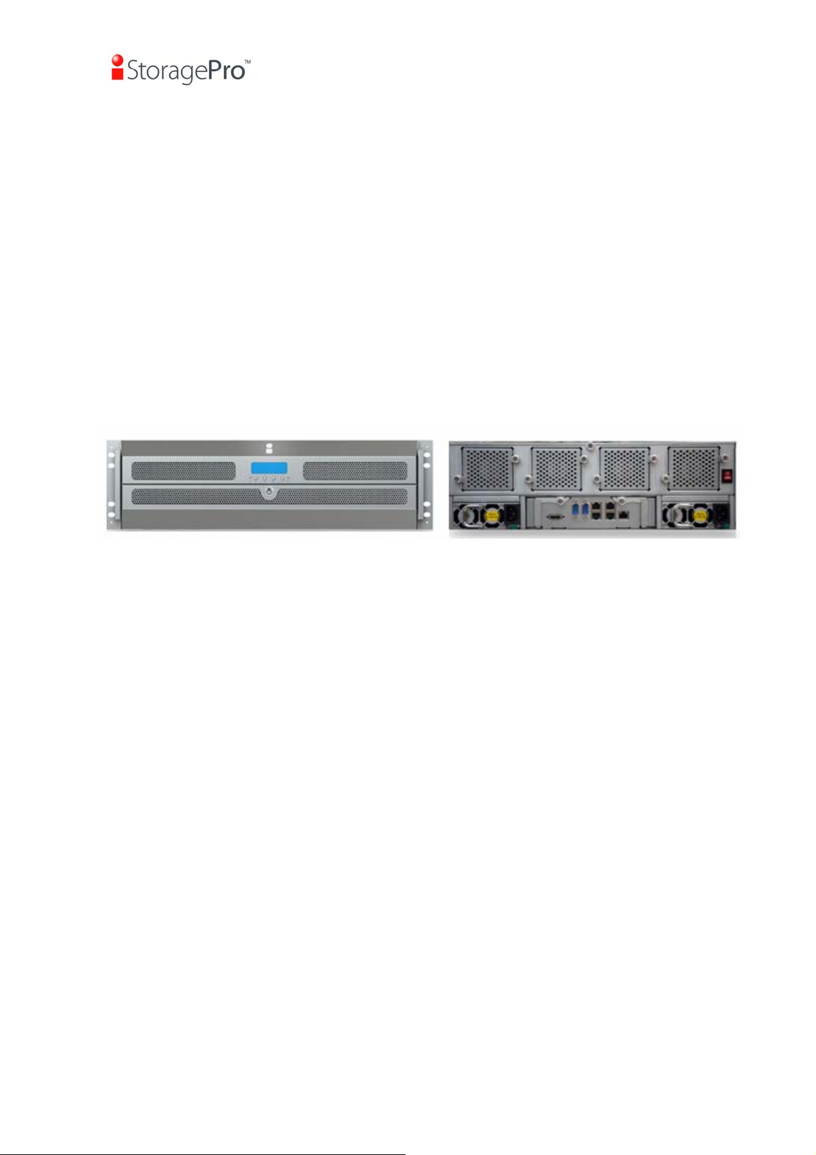
The controller of iR16IS4ER connects to the host system by iSCSI interface. It can
be configured to numerous RAID level. The controller provides reliable data
protection for servers by using RAID 6. The RAID 6 allows two HDD failures without
any impact on the existing data. Data can be recovered from the existing data and
parity drives. (Data can be recovered from the rest drives.)
Front View Rear View
Figure 1.1.1 iR16IS4ER
Snapshot-on-the-box (iSnap) is a fully usable copy of a defined collection of data
that contains an image of the data as it appeared at the point in time, which means a
point-in-time data replication. It provides consistent and instant copies of data
volumes without any system downtime. Snapshot-on-the-box can keep up to 32
snapshots for one logical volume. Rollback feature is provided for restoring the
previous-snapshot data easily while continuously using the volume for further data
access. The data access which includes read / write is working as usual without any
impact to end users. The "on-the-box" implies that it does not require any proprietary
agents installed at host side. The snapshot is taken at target side. It will not consume
any host CPU time thus the server is dedicated to the specific or other application.
The snapshot copies can be taken manually or by schedule every hour or every day,
depends on the modification.
iStoragePro controller is the most cost-effective disk array system with completely
integrated high-performance and data-protection capabilities which meet or exceed
the highest industry standards, and the best data solution for small / medium
business (SMB) users.
- 8 -

iR16IS4ER
1.1.1 Highlights
• iStoragePro Controller feature highlights
1. Front-end 4-ported iSCSI GbE ports with load-balancing and failover for high
availability
2. Hardware iSCSI off-load engine enabled
3. RAID 6, 60
4. iSnap without relying on host software
5. iSCSI jumbo frame support
6. Header/Data digest support
7. SATAII drive backward-compatible
8. One logic volume can be shared by as many as 8 hosts
One logic volume can be shared by as many as 16 hosts
9. Host access control
10. Configurable N-way mirror for high data protection
11. On-line volume migration with no system down-time
12. HDD S.M.A.R.T. enabled for SATA drives
13. SAS JBOD expansion support
14. Windows VSS support
15. Disk auto spindown support
16. Virtual disk clone function.(The detail step please refer to The Quick Guide How_to_perform_VD_clone_function
17. BOOTP support on management port.
1.1.2 Technical specifications
• Key components
1. CPU : Intel Xscale IOP 81342
2. Memory : 1GB ~ 2 GB DDRII 533 DIMM supported
3. 32MB flash
4. UARTs : support for serial console management and UPS
5. Fast Ethernet port for web-based management use.
6. Backend : Up to 24 SAS 3.0Gb/s, or SATA 1.0, 1.5Gb/s or SATA 2.0, 3Gb/s
disks supported on the controller board
7. Front-end : Two Intel GbE NIC controllers
8. LCM supported for easy management use
9. Battery backup support (optional)
• RAID and volume operation
1. RAID level: 0,1,0+1,3,5,6,10,30,50, 60 and JBOD
2. Up to 1024 logical volumes in the system
3. Up to 16 PDs can be included in one volume group
4. Global and dedicated hot spare disks
5. Write-through or write-back cache policy for different application usage
6. Multiple RAID volumes support
- 9 -

iR16IS4ER
7. Configurable RAID stripe size
8. Online volume expansion
9. Instant RAID volume availability
10. Auto volume rebuilding
11. Online volume migration
• Advanced data protection
1. iSnap
2. Local N-way mirror
3. On-line disk roaming
4. Smart faulty sector relocation
5. Battery backup support (optional)
• Enclosure monitoring
1. S.E.S. support for standard enclosure management
2. UPS management via the specific serial port
3. Fan speed monitoring fan x4
4. Redundant power supply monitor
5. 3.3V, 5V and 12V voltage monitor
6. Thermal sensors x 3 on the controller BOARD (for CPU, bridge and host channel
chip)
7. Thermal sensor x 3 (up to 24) in enclosure.
8. Status report of the managed iR16SAEJ SAS/SATA JBODs
• Management interface
1. Management UI via serial console, SSH telnet, HTTP Web UI, and secured Web
(HTTPS)
2. Online system firmware upgrade mechanism
3. Event notification via Email, SNMP trap, browser pop-up windows, Syslog, and
Windows Messenger.
4. Run-time IO transactions recording
5. Built-in LCD module to control most enclosure components
6. iSNS and DHCP support
7. CHAP authentication enabled
• Host connection
1. 4 x GbE ports support independent access, failover and load-balancing (802.3ad
port trunking, LACP)
2. Multiple iSCSI target nodes support
3. Microsoft MPIO enabled
4. iSCSI jumbo frame support
5. Header/Data digest support
6. LUN access control: Read-Write and Read-Only
7. Up to 128 sessions
8. Up to 16 hosts clustered for one volume
9. Support Windows, Linux and Mac OS
- 10 -
iR16IS4ER
• Drive support
1. SCSI-3 compliant
2. Multiple IO transaction processing
3. Tagged command queuing
4. Hard drive S.M.A.R.T. enabled for SATA drives
5. Up to 4 iStoragePro iR16SAEJ SAS JBODs can be connected to one
iR16IS4ER by using the SAS JBOD port
6. The overall SAS/SATA drives supported for one controller is up to 16+4*16 = 80
SAS/SATA drives
• Chassis integration
1. Controller Board Assembly of iR16IS4ER form factor
Dimension: 14.5 cm x 28 cm x 3.2 cm (W x D x H)
2. VHDM-HSD connector to customized backplane, designed with all interfaces
mounted on-board exposed to external via customized IO bracket
1.2 RAID concepts
RAID is the abbreviation of “Redundant Array of Independent Disks”. The basic idea
of RAID is to combine multiple drives together to form one large logical drive. This
RAID drive obtains performance, capacity and reliability than a single drive. The
operating system detects the RAID drive as a single storage device.
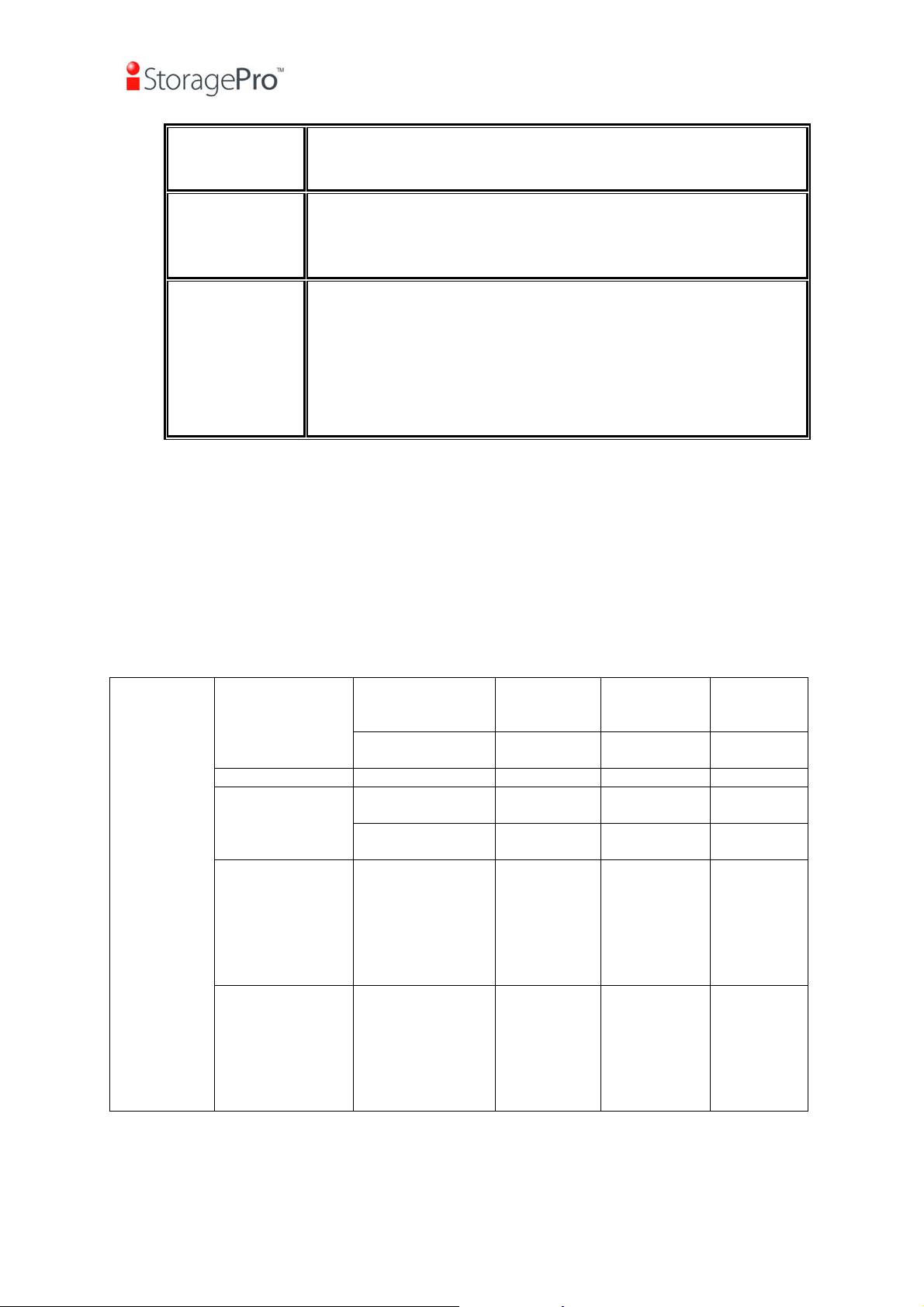
1.2.1 Terminology
The document uses the following terms:
• Part 1: Common
RAID
PD
Redundant Array of Independent Disks. There are different
RAID levels with different degree of data protection, data
availability, and performance to host environment.
The Physical Disk belongs to the member disk of one specific
RAID group.
RG
VD
LUN
Raid Group. A collection of removable media. One RG consists
of a set of VDs and owns one RAID level attribute.
Virtual Disk. Each RD could be divided into several VDs. The
VDs from one RG have the same RAID level, but may have
different volume capacity.
Logical Unit Number. A logical unit number (LUN) is a unique
- 11 -
iR16IS4ER
identifier which enables it to differentiate among separate
devices (each one is a logical unit).
GUI
RAID cell
WT
WB
Graphic User Interface.
When creating a RAID group with a compound RAID level, such
as 10, 30, 50 and 60, this field indicates the number of
subgroups in the RAID group. For example, 8 disks can be
grouped into a RAID group of RAID 10 with 2 cells, 4 cells. In
the 2-cell case, PD {0, 1, 2, 3} forms one RAID 1 subgroup and
PD {4, 5, 6, 7} forms another RAID 1 subgroup. In the 4-cells,
the 4 subgroups are PD {0, 1}, PD {2, 3}, PD {4, 5} and PD
{6,7}.
Write-Through cache-write policy. A caching technique in which
the completion of a write request is not signaled until data is
safely stored in non-volatile media. Each data is synchronized in
both data cache and accessed physical disks.
Write-Back cache-write policy. A caching technique in which the
completion of a write request is signaled as soon as the data is
in cache and actual writing to non-volatile media occurs at a
later time. It speeds up system write performance but needs to
bear the risk where data may be inconsistent between data
cache and the physical disks in one short time interval.
RO
DS
GS
DG
SCSI
SAS
S.M.A.R.T.
WWN
Set the volume to be Read-Only.
Dedicated Spare disks. The spare disks are only used by one
specific RG. Others could not use these dedicated spare disks
for any rebuilding purpose.
Global Spare disks. GS is shared for rebuilding purpose. If
some RGs need to use the global spare disks for rebuilding,
they could get the spare disks out from the common spare disks
pool for such requirement.
DeGraded mode. Not all of the array’s member disks are
functioning, but the array is able to respond to application read
and write requests to its virtual disks.
Small Computer Systems Interface.
Serial Attached SCSI.
Self-Monitoring Analysis and Reporting Technology.
World Wide Name.
HBA
SES
Host Bus Adapter.
SCSI Enclosure Services.
- 12 -
iR16IS4ER
NIC
BBM
• Part 2: iSCSI
iSCSI
LACP
MPIO
MC/S
MTU
CHAP
iSNS
Network Interface Card.
Battery Backup Module
Internet Small Computer Systems Interface.
Link Aggregation Control Protocol.
Multi-Path Input/Output.
Multiple Connections per Session
Maximum Transmission Unit.
Challenge Handshake Authentication Protocol. An optional
security mechanism to control access to an iSCSI storage
system over the iSCSI data ports.
Internet Storage Name Service.
1.2.2 RAID levels
There are different RAID levels with different degree of data protection, data
availability, and performance to host environment. The description of RAID levels are
on the following:
RAID 0
RAID 1
N-way mirror
RAID 3
RAID 5
RAID 6
Disk striping. RAID 0 needs at least one hard drive.
Disk mirroring over two disks. RAID 1 needs at least two hard
drives.
Extension to RAID 1 level. It has N copies of the disk.
Striping with parity on the dedicated disk. RAID 3 needs at least
three hard drives.
Striping with interspersed parity over the member disks. RAID 3
needs at least three hard drives.
2-dimensional parity protection over the member disks. RAID 6
needs at least four hard drives.
RAID 0+1
RAID 10
Mirroring of the member RAID 0 volumes. RAID 0+1 needs at
least four hard drives.
Striping over the member RAID 1 volumes. RAID 10 needs at
least four hard drives.
- 13 -
iR16IS4ER
RAID 30
RAID 50
RAID 60
JBOD
Striping over the member RAID 3 volumes. RAID 30 needs at
least six hard drives.
Striping over the member RAID 5 volumes. RAID 50 needs at
least six hard drives.
Striping over the member RAID 6 volumes. RAID 60 needs at
least eight hard drives.
The abbreviation of “Just a Bunch Of Disks”. JBOD needs at
least one hard drive.
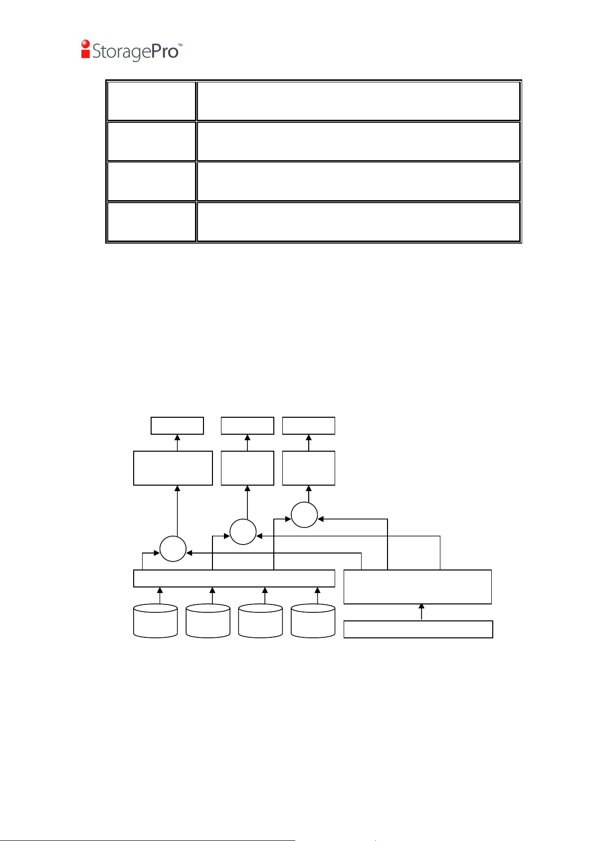
1.2.3 Volume relationship
The below graphic is the volume structure which iStoragePro has designed. It
describes the relationship of RAID components. One RG (RAID group) consists of a
set of VDs (Virtual Disk) and owns one RAID level attribute. Each RG can be divided
into several VDs. The VDs in one RG share the same RAID level, but may have
different volume capacity. All VDs share the CV (Cache Volume) to execute the data
transaction. LUN (Logical Unit Number) is a unique identifier, in which users can
access through SCSI commands.
VD 1 VD 2
+
+
PD 2 PD 3 DS PD 1
iSnap
VD
+
Cache Volume
Figure 1.2.3.1
1.3 iSCSI concepts
iSCSI (Internet SCSI) is a protocol which encapsulates SCSI (Small Computer
System Interface) commands and data in TCP/IP packets for linking storage devices
with servers over common IP infrastructures. iSCSI provides high performance SANs
over standard IP networks like LAN, WAN or the Internet.
- 14 -

iR16IS4ER
IP SANs are true SANs (Storage Area Networks) which allow several servers to
attach to an infinite number of storage volumes by using iSCSI over TCP/IP networks.
IP SANs can scale the storage capacity with any type and brand of storage system.
In addition, it can be used by any type of network (Ethernet, Fast Ethernet, Gigabit
Ethernet, and 10 Gigabit Ethernet) and combination of operating systems (Microsoft
Windows, Linux, Solaris, Mac, etc.) within the SAN network. IP-SANs also include
mechanisms for security, data replication, multi-path and high availability.
Storage protocol, such as iSCSI, has “two ends” in the connection. These ends are
initiator and target. In iSCSI, we call them iSCSI initiator and iSCSI target. The iSCSI
initiator requests or initiates any iSCSI communication. It requests all SCSI
operations like read or write. An initiator is usually located on the host side (either an
iSCSI HBA or iSCSI SW initiator).
The target is the storage device itself or an appliance which controls and serves
volumes or virtual volumes. The target is the device which performs SCSI command
or bridge to an attached storage device.
Host 1
(initiator)
NIC
Host 2
(initiator)
iSCSI
HBA
IP SAN
iSCSI device 1
(target)
iSCSI device 2
(target)
Figure 1.3.1
The host side needs an iSCSI initiator. The initiator is a driver which handles the
SCSI traffic over iSCSI. The initiator can be software or hardware (HBA). Please refer
to the certification list of iSCSI HBA(s) in Appendix A. OS native initiators or other
software initiators use standard TCP/IP stack and Ethernet hardware, while iSCSI
HBA(s) use their own iSCSI and TCP/IP stacks on board.
Hardware iSCSI HBA(s) provide its own initiator tool. Please refer to the vendors’
HBA user manual. Microsoft, Linux, Solaris and Mac provide iSCSI initiator driver.
Please contact iStoragePro for the latest certification list. Below are the available
links:
1. Link to download the Microsoft iSCSI software initiator:
85
Hhttp://www.microsoft.com/downloads/details.aspx?FamilyID=12cb3c1a-15d6-
4585-b385-befd1319f825&DisplayLang=en
- 15 -

iR16IS4ER
2. In current Linux distributions, OS built-in iSCSI initiators are usually available.
For different kernels, there are different iSCSI drivers. Please check Appendix A
for iSCSI initiator certification list. If user needs the latest Linux iSCSI initiator,
please visit Open-iSCSI project for most update information. Linux-iSCSI (sfnet)
and Open-iSCSI projects merged in April 11, 2005.
Open-iSCSI website:
Open-iSCSI README:
Features:
88
Hhttp://www.open-iscsi.org/cgi-bin/wiki.pl/Roadmap
86
Hhttp://www.open-iscsi.org/
87
Hhttp://www.open-iscsi.org/docs/README
Support Kernels:
89
Hhttp://www.open-iscsi.org/cgi-bin/wiki.pl/Supported_Kernels
Google groups:
90
Hhttp://groups.google.com/group/open-iscsi/threads?gvc=2
91
Hhttp://groups.google.com/group/open-iscsi/topics
Open-iSCSI Wiki:
92
Hhttp://www.open-iscsi.org/cgi-bin/wiki.pl
3. ATTO iSCSI initiator is available for Mac.
Website:
93
Hhttp://www.attotech.com/xtend.html
4. Solaris iSCSI initiator
Version: Solaris 10 u6 (10/08)
- 16 -
iR16IS4ER
Chapter 2 Installation
2.1 Package contents
The package contains the following items:
- One iR16IS4ER-N: Gigabit LAN (x4) -to- SATA II/SAS RAID controller.
- One Ethernet Cross over cable
Not included: (Optional) 4 X RJ45 Gbits Straight Ethernet Data Cable
(Optional) 1 X Serial 232 Cable
Contact your supplier if any of the above items are missing or damaged.
The RAM size for IR16IS4ER is recommended DDR2-533 1GB or above. Please
refer to the certification list in Appendix A.
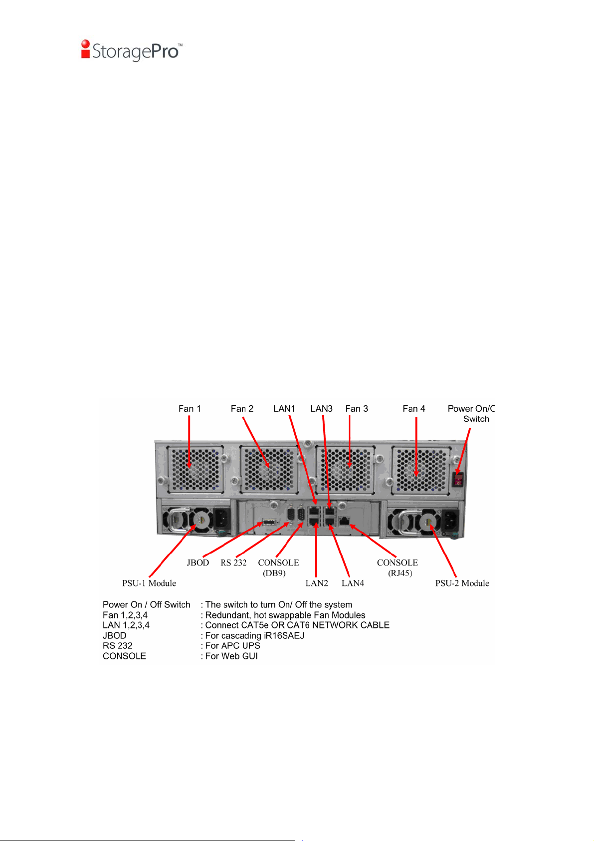
2.2 The Enclosure Description
Figure 2.2.1
- 17 -

iR16IS4ER
2.3 Make the system connected
Before starting, prepare the following items.
1. Check “Certification list” in Appendix A to confirm the hardware setting is fully
supported.
2. Read the latest release note before upgrading. Release note accompanies with
its released firmware.
3. A host with a Gigabit Ethernet NIC or iSCSI HBA.
4. CAT 5e, or CAT 6 network cables for management port and iSCSI data ports.
Recommend CAT 6 cables for best performance.
5. Prepare storage system configuration plan.
6. Prepare management port and iSCSI data ports network information. When
using static IP, please prepare static IP addresses, subnet mask, and default
gateway.
7. Gigabit switches (recommended). Or Gigabit switches with LCAP / Trunking
8. CHAP security information, including CHAP username and secret (optional).
9. Setup the hardware connection before power on servers. Connect console cable,
management port cable, and iSCSI data port cables in advance.
10. In addition, installing an iSNS server is recommended.
11. Power on iR16IS4ER first, and then power on hosts and iSNS server.
Chapter 3 Quick setup
3.1 Management interfaces
There are three management methods to manage iStoragePro controller, describe
in the following:
3.1.1 Serial console
Use console cable (NULL modem cable) to connect from console port of
iStoragePro controller to RS 232 port of management PC. Please refer to figure
2.3.1. The console settings are on the following:
Baud rate: 115200, 8 data bit, no parity, 1 stop bit, and no flow control.
Terminal type: vt100
Login name: admin
Default password: 0000
3.1.2 Remote control
SSH (secure shell) software is required for remote login. The SSH client software is
available at the following web site:
SSH Tectia Client:
PuTTY:
95
Hhttp://www.chiark.greenend.org.uk/
94
Hhttp://www.ssh.com/
- 18 -
iR16IS4ER
Host name: 192.168.10.50 (Please check the DHCP address first on LCM.)
Login name: admin
Default password: 0000
Tips
iStoragePro controller only supports SSH for remote control. For
using SSH, the IP address and password are required for login.
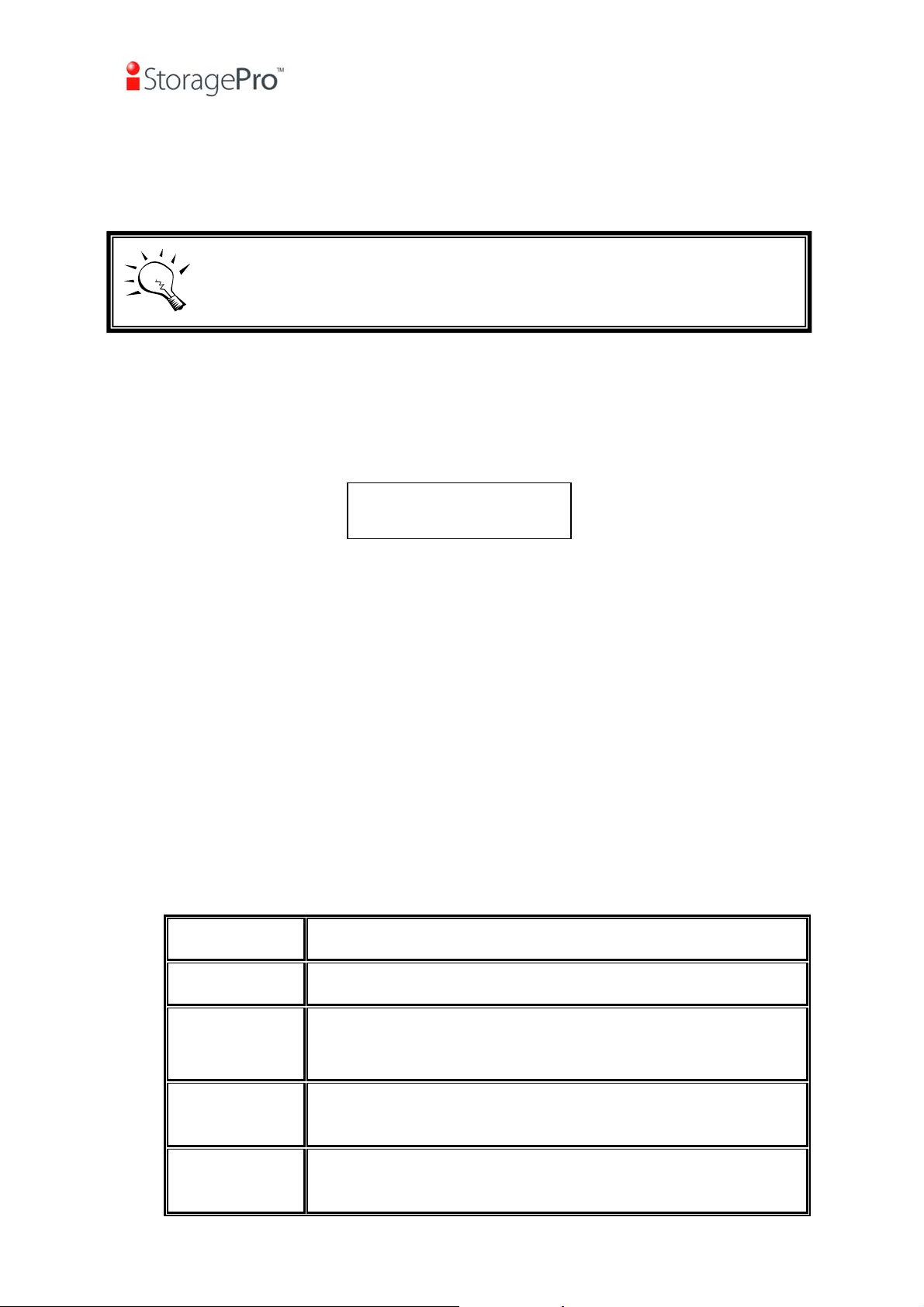
3.1.3 LCM
After booting up the system, the following screen shows management port IP and
model name:
Press “Enter” button, the LCM functions “System Info.”, “Alarm Mute”,
“Reset/Shutdown”, “Quick Install”, “Volume Wizard”, “View IP Setting”,
“Change IP Config” and “Reset to Default” will rotate by pressing c (up) and d
(down).
When there is WARNING event or ERROR event occurred (LCM default filter), the
LCM shows the event log to give users more detail from front panel.
The following table is function description of each item.
192.168.10.50
iStoragePro iR16IS4ER
Figure 3.1.3.1
• LCM operation description:
System Info.
Alarm Mute
Reset/
Display system information.
Mute alarm when error occurs.
Reset or shutdown controller.
Shutdown
Quick Install
Quick steps to create a volume. Please refer to next
chapter for detailed operation steps in web UI.
Volume
Wizard
Smart steps to create a volume. Please refer to next
chapter for detailed operation steps in web UI.
- 19 -
iR16IS4ER
View IP
Setting
Change IP
config
Reset to
Default
Display current IP address, subnet mask, and gateway.
Set IP address, subnet mask, and gateway. There are 2
options: DHCP (Get IP address from DHCP server) or
static IP.
Reset to default will set password to default: 0000, and set
IP address to default as DHCP setting.
Default IP address: 192.168.10.50 (DHCP)
Default subnet mask: 255.255.255.0
Default gateway: 192.168.10.254
• LCM menu hierarchy:
iStoragePro
Technology
cd
[System Info.]
[Alarm Mute] [cYes Nod]
[Reset/Shutdown]
[Quick Install]
[Volume Wizard]
[Firmware
Version
x.x.x]
[RAM Size
xxx MB]
[Reset]
[Shutdown]
RAID 0
RAID 1
RAID 3
RAID 5
RAID 6
RAID 0+1
xxx GB
[Local]
RAID 0
RAID 1
RAID 3
RAID 5
RAID 6
RAID 0+1
[cYes
Nod]
[cYes
Nod]
[Apply The
Config]
[Use default
algorithm]
[cYes
Nod]
[Volume
Size]
xxx GB
[Apply The
Config]
[cYes
Nod]
- 20 -
[JBOD x] cd
RAID 0
RAID 1
RAID 3
RAID 5
RAID 6
RAID 0+1
[IP Config]
[Static IP]
[IP Address]
[View IP Setting]
[Change IP
Config]
[Reset to Default] [cYes Nod]
[192.168.010.050]
[IP Subnet Mask]
[255.255.255.0]
[IP Gateway]
[192.168.010.254]
[DHCP]
[Static IP]
[new x disk]
cd
xxx BG
[cYes
Nod]
[IP Address]
[IP Subnet
Mask]
[IP
Gateway]
[Apply IP
Setting]
iR16IS4ER
Adjust
Volume Size
Adjust IP
address
Adjust
Submask IP
Adjust
Gateway IP
[cYes
Nod]
[Apply The
Config]
[cYes
Nod]
Caution
Before power off, it is better to execute “Shutdown” to flush the data
from cache to physical disks.
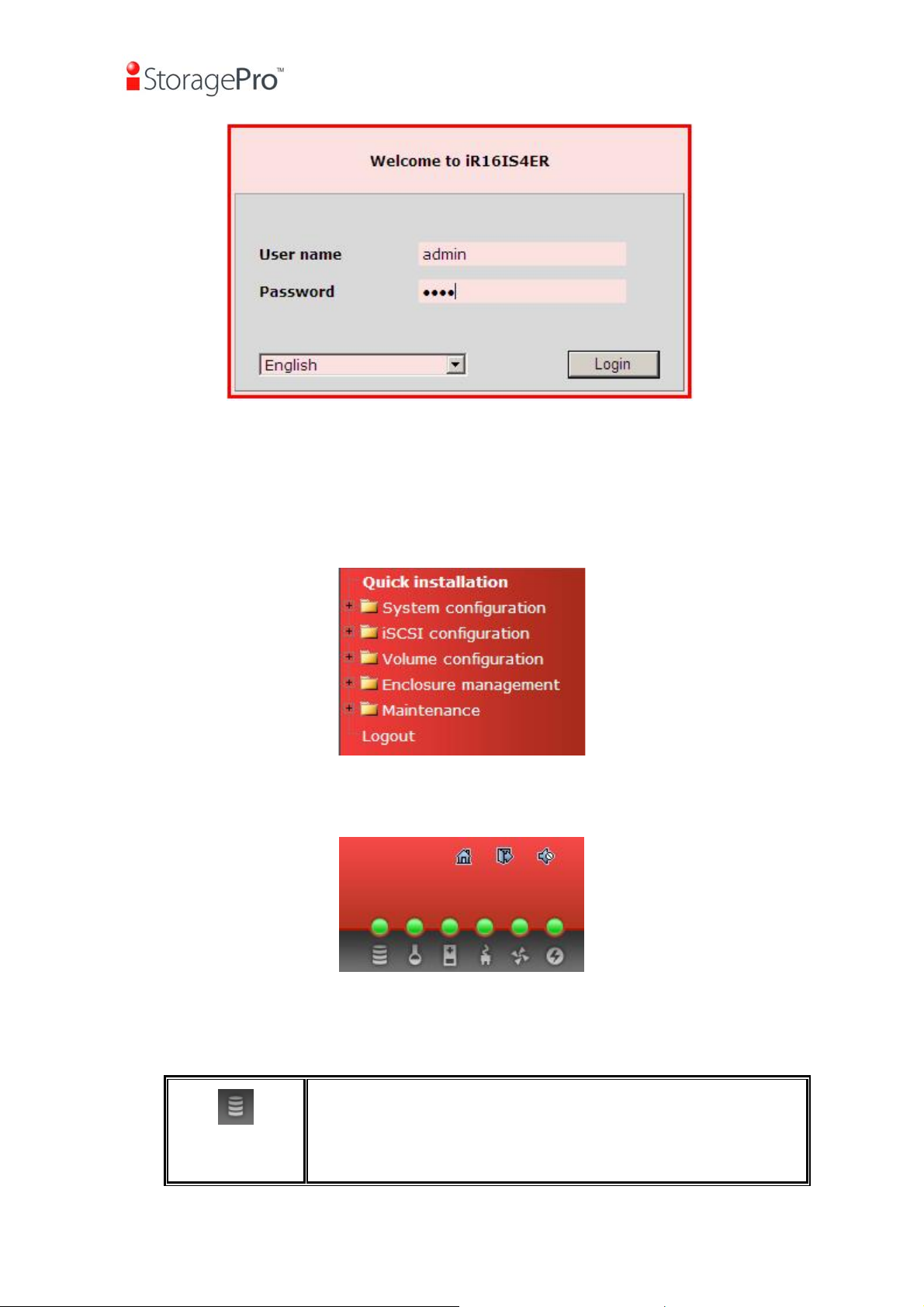
3.1.4 Web UI
iStoragePro controller supports graphic user interface (GUI) to operate. Be sure to
connect the LAN cable. The default IP setting is DHCP; open the browser and enter:
http://192.168.10.50 (Please check the DHCP address first on LCM.)
And then it will pop up a dialog for authentication.
- 21 -
iR16IS4ER
Figure 3.1.4.1
User name: admin
Default password: 0000
After login, choose the functions which lists on the left side of window to make any
configuration.
Figure 3.1.4.2
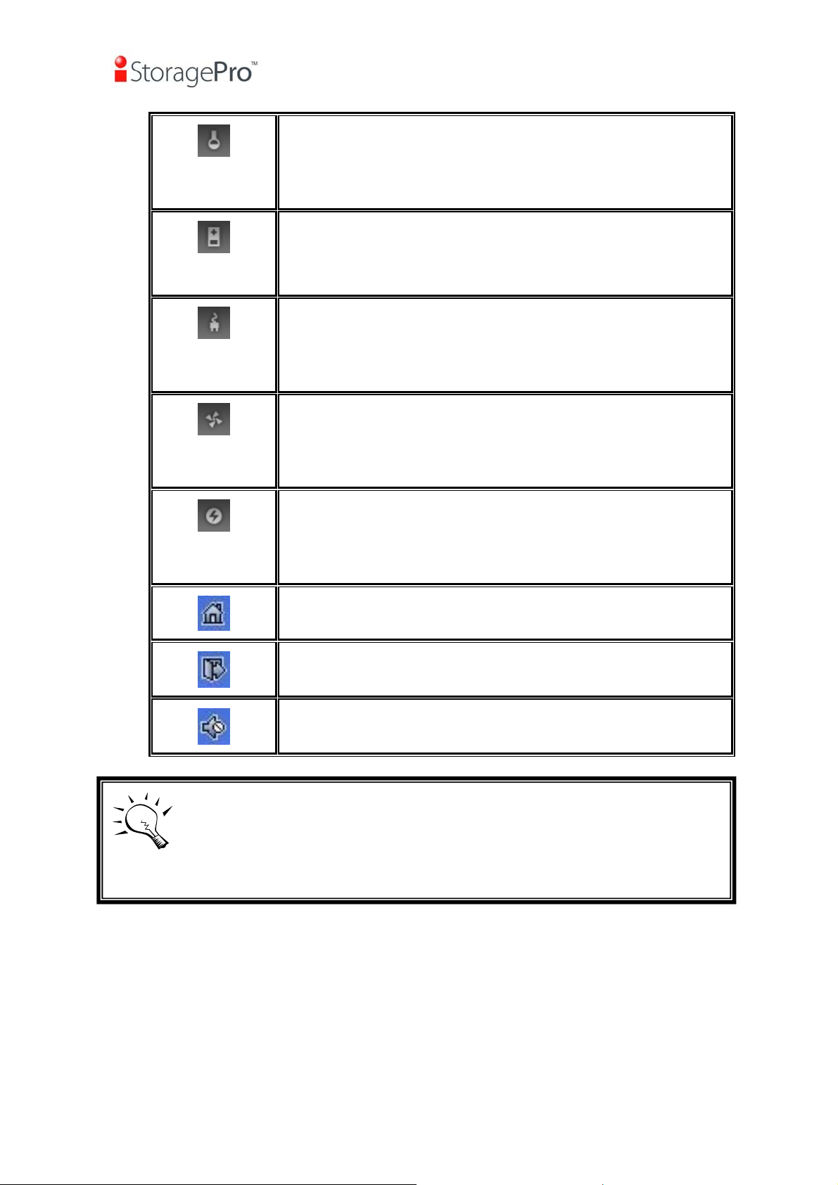
There are six indicators at the top-right corner for backplane solutions.
• Indicator description:
Figure 3.1.4.3
RAID light:
x Green Æ RAID works well.
x Red Æ RAID fails.
- 22 -
iR16IS4ER
Temperature light:
x Green Æ Temperature is normal.
x Red Æ Temperature is abnormal.
Voltage light:
x Green Æ voltage is normal.
x Red Æ voltage is abnormal.
UPS light:
x Green Æ UPS works well.
x Red Æ UPS fails.
Fan light:
x Green Æ Fan works well.
x Red Æ Fan fails.
Power light:
x Green Æ Power works well.
x Red Æ Power fails.
Return to home page.
Logout the management web UI.
Mute alarm beeper.
Tips
If the status indicators in Internet Explorer (IE) are displayed in gray,
but not in blinking red, please enable “Internet Options” Æ
“Advanced” Æ “Play animations in webpages” options in IE. The
default value is enabled, but some applications will disable it.
3.2 How to use the system quickly
The following methods will describe the quick guide to use this controller.
3.2.1 Quick installation
- 23 -
iR16IS4ER
It is easy to use “Quick install” to create a volume. It uses whole physical disks to
create a RG; the system will calculate maximum spaces on RAID levels 0 / 1 / 3 / 5 /
6 / 0+1. “Quick install” will occupy all residual RG space for one VD, and it has no
space for snapshot and spare. If snapshot is needed, please create volumes by
manual, and refer to section 5.4 for more detail. If some physical disks are used in
other RGs, “Quick install” can not be run because the operation is valid only when
all physical disks in this system are free.
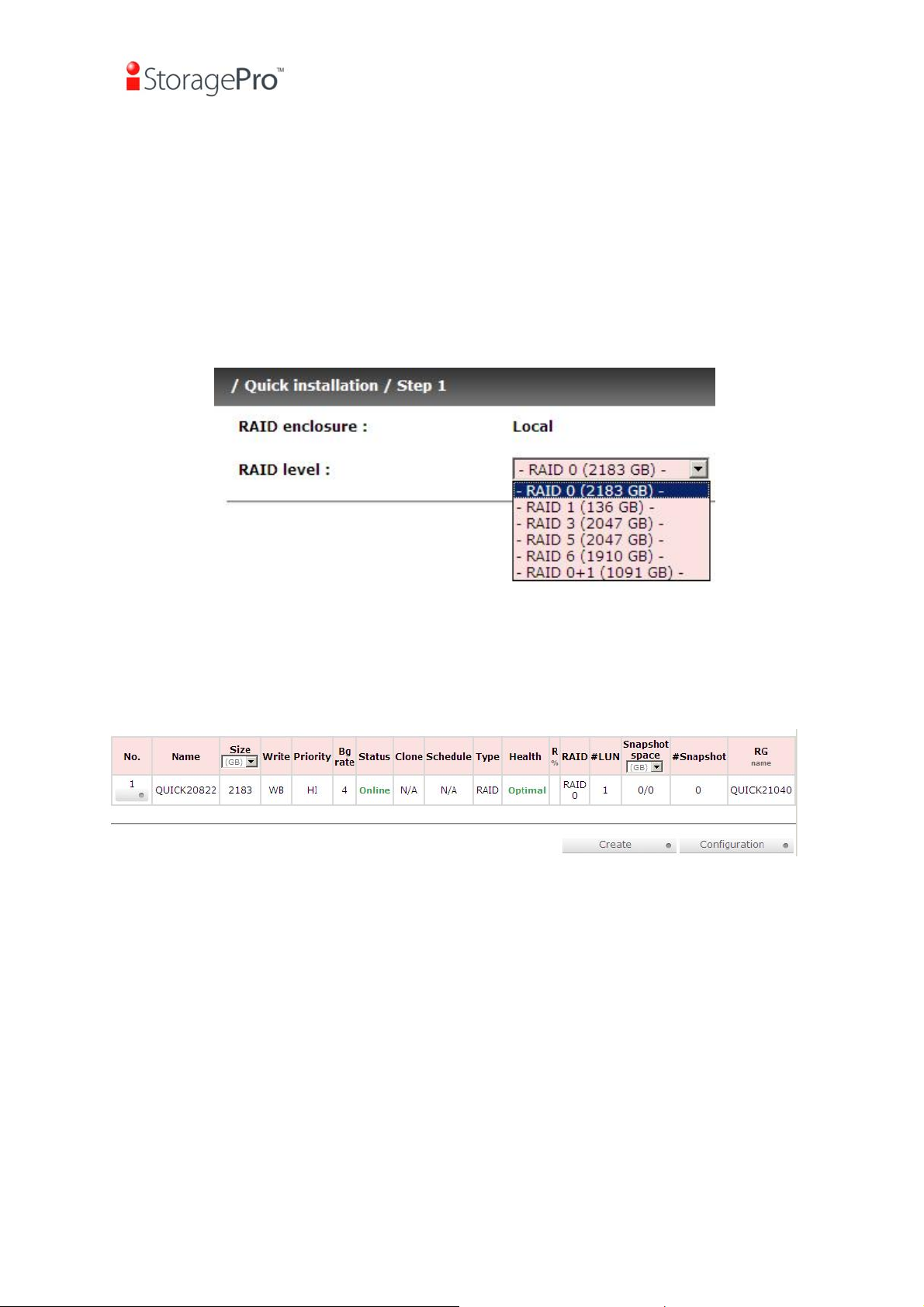
Step 1: Click “Quick install”, then choose the RAID level. After choosing the RAID
level, then click “Confirm”. It will link to another page.
Figure 3.2.1.1
Step 2: Confirm page. Click “Confirm” if all setups are correct. Then a VD will be
created.
Step 3: Done. You can start to use the system now.
Figure 3.2.1.2
(Figure 3.2.1.2: A virtual disk of RAID 0 is created and is named by system itself.)
3.2.2 Volume creation wizard
“Volume create wizard” has a smarter policy. When the system is inserted with
some HDDs. “Volume create wizard” lists all possibilities and sizes in different RAID
levels, it will use all available HDDs for RAID level depends on which user chooses.
When system has different sizes of HDDs, e.g., 8*200G and 8*80G, it lists all
possibilities and combination in different RAID level and different sizes. After user
- 24 -
iR16IS4ER
chooses RAID level, user may find that some HDDs are available (free status). The
result is using smarter policy designed by iStoragePro. It gives user:
1. Biggest capacity of RAID level for user to choose and,
2. The fewest disk number for RAID level / volume size.
E.g., user chooses RAID 5 and the system has 12*200G + 4*80G HDDs inserted. If
we use all 16 HDDs for a RAID 5, and then the maximum size of volume is 1200G
(80G*15). By the wizard, we do smarter check and find out the most efficient way of
using HDDs. The wizard only uses 200G HDDs (Volume size is 200G*11=2200G),
the volume size is bigger and fully uses HDD capacity.
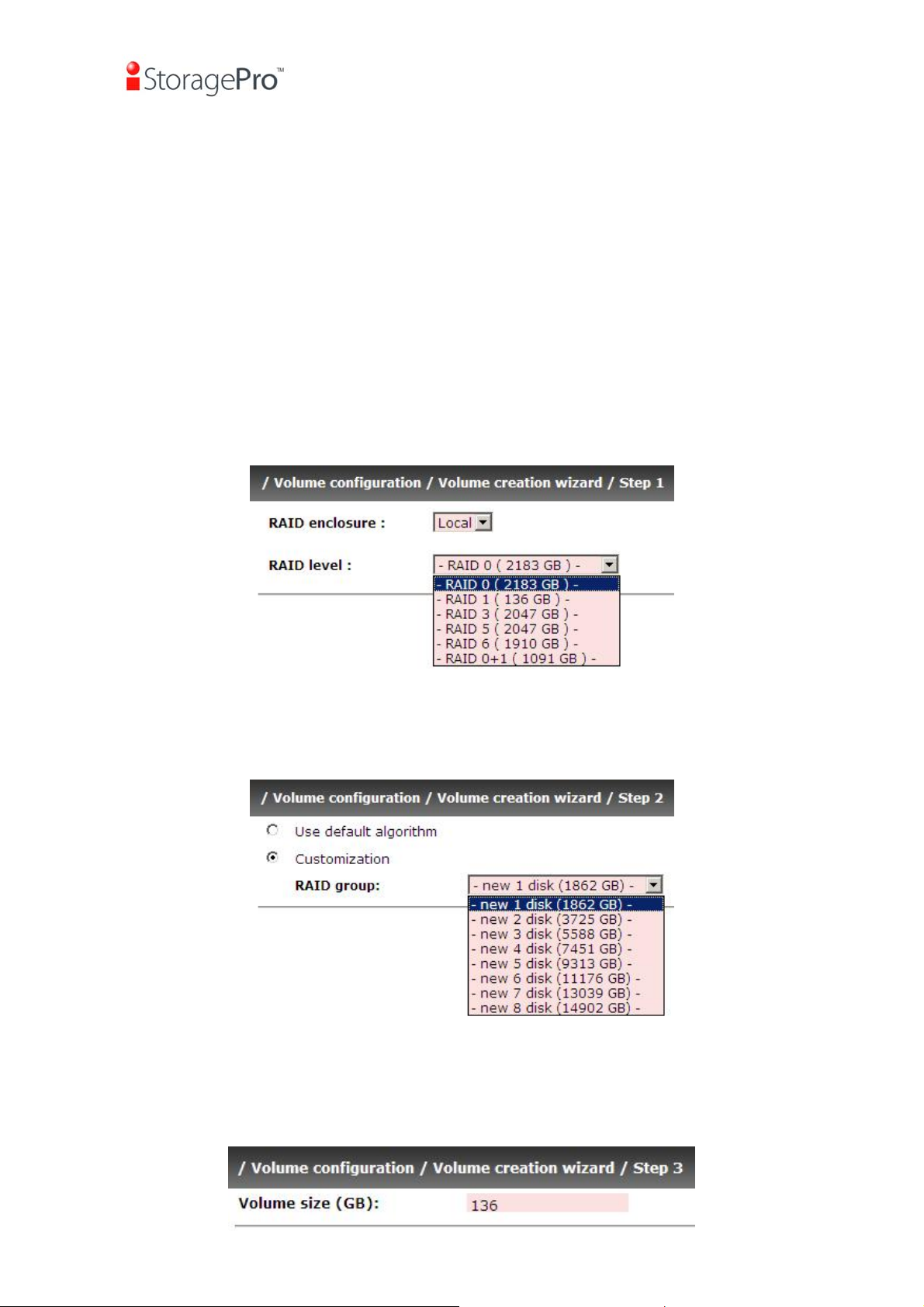
Step 1: Select “/ Volume configuration / Volume create wizard” and then choose
the RAID level. After the RAID level is chosen, click “Next”. Then it will link to next
page.
Figure 3.2.2.1
Step 2: Please select the combination of the RG capacity, or “Use default
algorithm” for maximum RG capacity. After RG size is chosen, click “Next”.
Figure 3.2.2.2
Step 3: Decide VD size. User can enter a number less or equal to the default number.
Then click “Next”.
- 25 -

Figure 3.2.2.3
iR16IS4ER
Step 4: Confirm page. Click “Confirm” if all setups are correct. Then a VD will be
created.
Step 5: Done. You can start to use the system now.
Figure 3.2.2.4
(Figure 3.2.2.4: A virtual disk of RAID 0 is created and is named by system itself.)
- 26 -

A
/
iR16IS4ER
Chapter 4 Configuration
4.1 Web UI management interface hierarchy
The below table is the hierarchy of web GUI.
Æ
Quick installation
System configuration
System setting
IP address
Login setting
Mail setting
Notification
iSCSI configuration
Entity property
CHAP account
Session
Volume configuration
Volume create
Physical disk
RAID group
Virtual disk
Snapshot
Logical unit
Enclosure management
configuration
Hardware
monitor
S.M.A.R.T.
Maintenance
information
Reset to default
Upgrade
setting
NIC
Node
wizard
SES
UPS
System
Step 1 / Step 2 / Confirm
System name / Date and time / System indication
Æ
MAC address / Address / DNS / port
Æ
Login configuration / Admin password / User password
Æ
Mail
Æ
SNMP / Messenger / System log server / Event log filter
Æ
Æ
Entity name / iSNS IP
ggregation / IP settings for iSCSI ports / Become default
Æ
gateway / Enable jumbo frame / Ping host
Create / Authenticate / Rename / User / Delete
Æ
Session information / Delete
Æ
Create / Modify user information / Delete
Æ
Step 1 / Step 2 / Step 3 / Step 4 / Confirm
Set Free disk / Set Global spare / Set Dedicated spare /
Æ
Disk Scrub / Upgrade / Turn on/off the indication LED /
More information
Create / Migrate / Move/ Activate / Deactivate / Parity
Æ
check / Delete / Set disk property / More information
Create / Extend / Parity check / Delete / Set property /
Æ
Attach LUN / Detach LUN / List LUN / Set clone / Clear
clone / Start clone / Stop clone / Schedule clone
snapshot space / Cleanup snapshot / Take snapshot /
Auto snapshot / List snapshot / More information
Cleanup / Auto snapshot / Take snapshot / Export /
Æ
Rollback / Delete
Attach / Detach
Æ
Enable / Disable
Æ
Auto shutdown
Æ
S.M.A.R.T. information
Æ
(Only for SATA disks)
UPS Type / Shutdown battery level / Shutdown delay /
Æ
Shutdown UPS
System information
Æ
Browse the firmware to upgrade / Export configuration
Æ
Sure to reset to factory default?
Æ
Set
- 27 -
Import/Export / Import file
Import and
Æ
iR16IS4ER
export
Download / Mute / Clear
Event log
Reboot and
Æ
Reboot / Shutdown
Æ
shutdown
Logout
Sure to logout?
4.2 System configuration
“System configuration” is designed for setting up the “System setting”, “IP
address”, “Login setting”, “Mail setting”, and “Notification setting”.
Figure 4.2.1
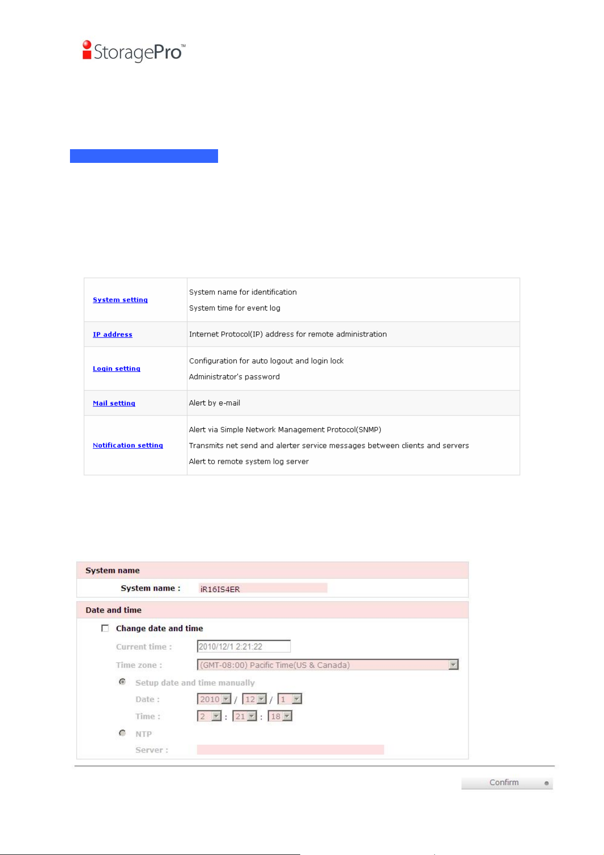
4.2.1 System Setting
“System setting” can setup system name and date. Default “System name” is
composed of model name and serial number of this system.
Figure 4.2.1.1
- 28 -

iR16IS4ER
Check “Change date and time” to set up the current date, time, and time zone
before using or synchronize time from NTP (Network Time Protocol) server. Click
“Confirm” in System indication to turn on the system indication LED. Click again to
turn off.
4.2.2 IP address
Figure 4.2.2.1
“IP address” is for changing IP address for remote administration usage. There are
two options, DHCP (Get IP address from DHCP server) and static IP. The default
setting is DHCP. User can change the HTTP, HTTPS, and SSH port number when
the default port number is not allowed on host.
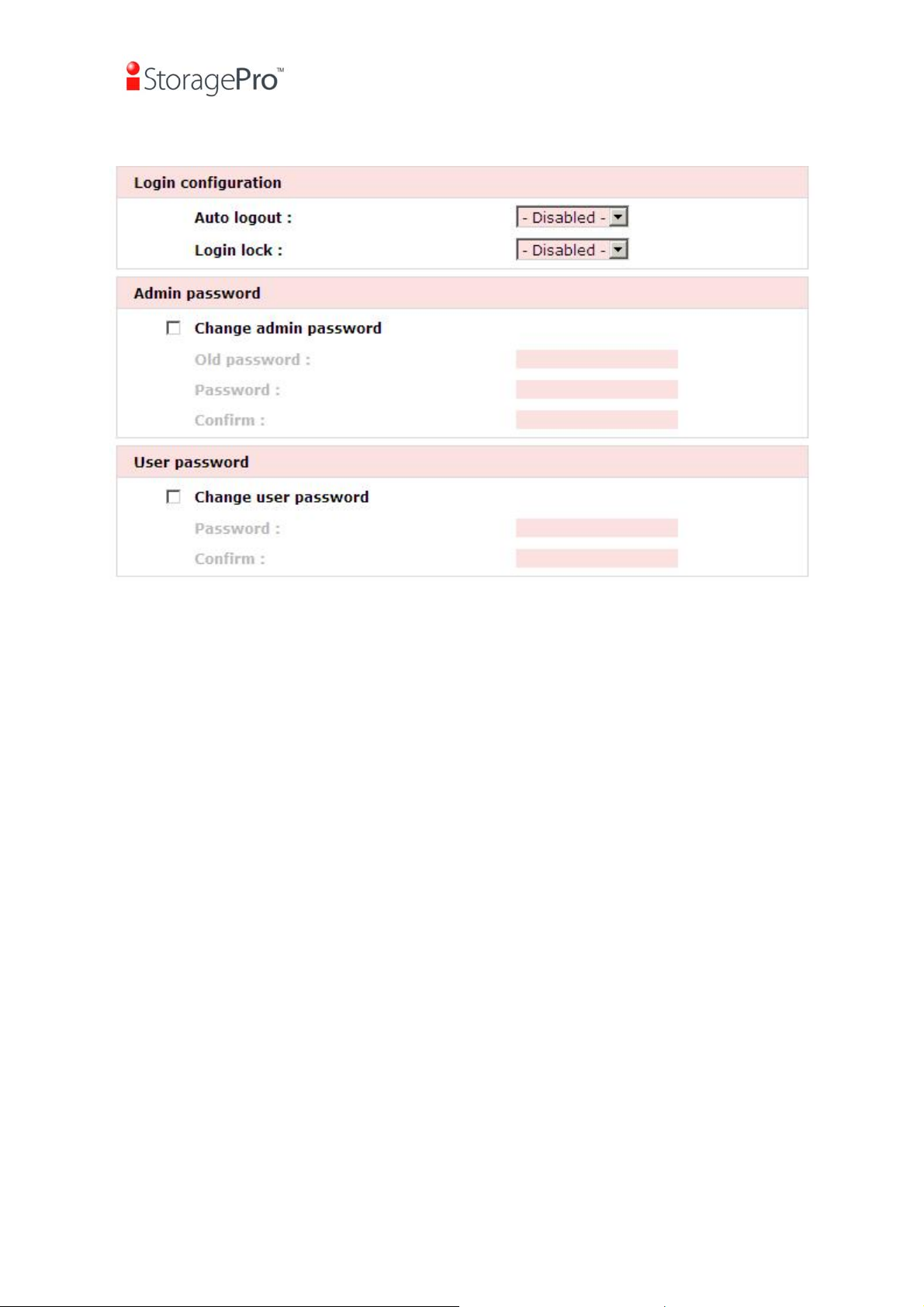
4.2.3 Login setting
“Login setting” can set single admin, auto logout time and admin / user password.
The single admin is to prevent multiple users access the same system in the same
time.
1. Auto logout: The options are (1) Disabled; (2) 5 minutes; (3) 30 minutes; (4) 1
hour. The system will log out automatically when user is inactive for a period of
time.
- 29 -
iR16IS4ER
2. Login lock: Disabled or Enabled. When the login lock is enabled, the system
allows only one user to login or modify system settings.
Figure 4.2.3.1
Check “Change admin password” or “Change user password” to change admin
or user password. The maximum length of password is 12 characters.
4.2.4 Mail setting
“Mail setting” can enter 3 mail addresses for receiving the event notification. Some
mail servers would check “Mail-from address” and need authentication for antispam. Please fill the necessary fields and click “Send test mail” to test whether
email functions are available. User can also select which levels of event logs are
needed to be sent via Mail. Default setting only enables ERROR and WARNING
event logs. Please also make sure the DNS server IP is well-setup so the event
notification mails can be sent successfully.
- 30 -
 Loading...